finite-element electrical machine simulation · finite-element electrical machine simulation in the...
TRANSCRIPT

Technische Universität Darmstadt, Fachbereich Elektrotechnik und InformationstechnikSchloßgartenstr. 8, 64289 Darmstadt, Germany - URL: www.TEMF.de
Dr.-
Ing.
Her
bert
De
Ger
sem
In
stitu
t für
The
orie
Ele
ktro
mag
netis
cher
Fel
der
Lecture Series
Finite-Element Electrical Machine Simulation
in the framework of the DFG Research Group 575„High Frequency Parasitic Effects
in Inverter-fed Electrical Drives”http://www.ew.e-technik.tu-darmstadt.de/FOR575
Dr.-Ing. Herbert De Gersemsummer semester 2006
Institut für Theorie Elektromagnetischer Felder
2
Dr.-
Ing.
Her
bert
De
Ger
sem
Inst
itut f
ür T
heor
ie E
lekt
rom
agne
tisch
er F
elde
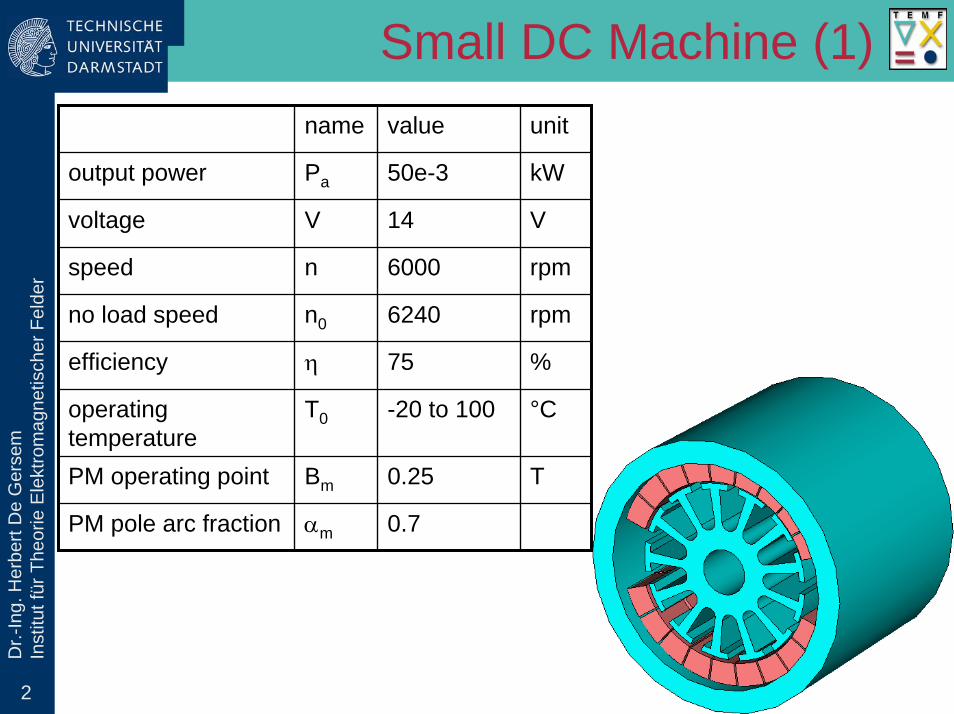
rSmall DC Machine (1)
name value unit
output power Pa 50e-3 kW
voltage V 14 V
speed n 6000 rpm
no load speed n0 6240 rpm
efficiency η 75 %
operating temperature
T0 -20 to 100 °C
PM operating point Bm 0.25 T
PM pole arc fraction αm 0.7

3
Dr.-
Ing.
Her
bert
De
Ger
sem
Inst
itut f
ür T
heor
ie E
lekt
rom
agne
tisch
er F
elde
r
Table 1: Motor data.
Schnitt A-
A
B
Schnitt C-
C
D
D
Lg
lm
dy
L
Lm = Ls
Small DC Machine (2)

4
Dr.-
Ing.
Her
bert
De
Ger
sem
Inst
itut f
ür T
heor
ie E
lekt
rom
agne
tisch
er F
elde
r
10.018.839.0
6.39
2.7
36.3R3.6
Small DC Machine (3)

5
Dr.-
Ing.
Her
bert
De
Ger
sem
Inst
itut f
ür T
heor
ie E
lekt
rom
agne
tisch
er F
elde
rSmall DC Machine (4)

6
Dr.-
Ing.
Her
bert
De
Ger
sem
Inst
itut f
ür T
heor
ie E
lekt
rom
agne
tisch
er F
elde
rSmall DC Machine (5)

7
Dr.-
Ing.
Her
bert
De
Ger
sem
Inst
itut f
ür T
heor
ie E
lekt
rom
agne
tisch
er F
elde
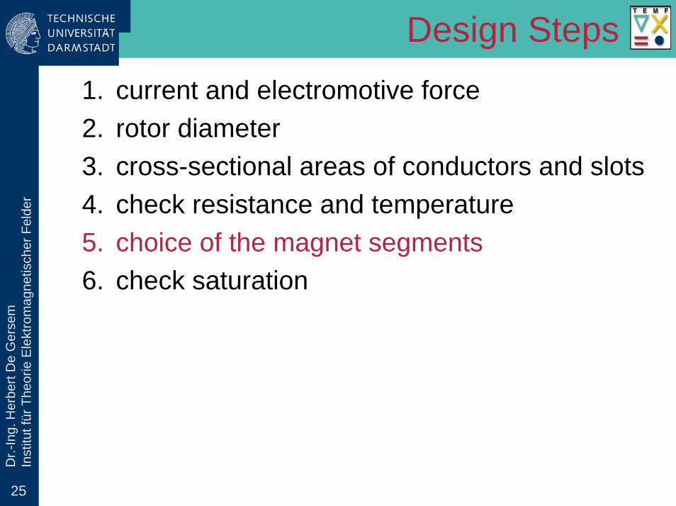
rDesign Steps
1. current and electromotive force2. rotor diameter3. cross-sectional areas of conductors and slots4. check resistance and temperature5. choice of the magnet segments6. check saturation

8
Dr.-
Ing.
Her
bert
De
Ger
sem
Inst
itut f
ür T
heor
ie E
lekt
rom
agne
tisch
er F
elde
rPower Balance
design step 1: current and electromotive force
mechP1.1. electrical power
mechel =
ηPP1.2. mechanical power
elP
mechP
el elη PJouleP
frictionP
el=PIU
1.3. current
el= ηE U1.4. electromotive force

9
Dr.-
Ing.
Her
bert
De
Ger
sem
Inst
itut f
ür T
heor
ie E
lekt
rom
agne
tisch
er F
elde
rLook-Up Table
look-up table (values by experience for PMDC motors with ferrites)
Pmech[W]
BL[T]
Ja[A/mm2]
AA[A/cm]
ηel[%]
η[%]
57.5102030405075100150200250
0,2 ... 0,230,2 ... 0,230,240,250,260,270,280,30,310,32 ... 0,350,350,4
9.49.29.08.47.97.57.16.76.46.16.06.0
40455060708090100100110120120
596265697274757778798080
222528354044465053565758

10
Dr.-
Ing.
Her
bert
De
Ger
sem
Inst
itut f
ür T
heor
ie E
lekt
rom
agne
tisch
er F
elde
rDesign Steps
1. current and electromotive force2. rotor diameter3. cross-sectional areas of conductors and slots4. check resistance and temperature5. choice of the magnet segments6. check saturation
11
Dr.-
Ing.
Her
bert
De
Ger
sem
Inst
itut f
ür T
heor
ie E
lekt
rom
agne
tisch
er F
elde
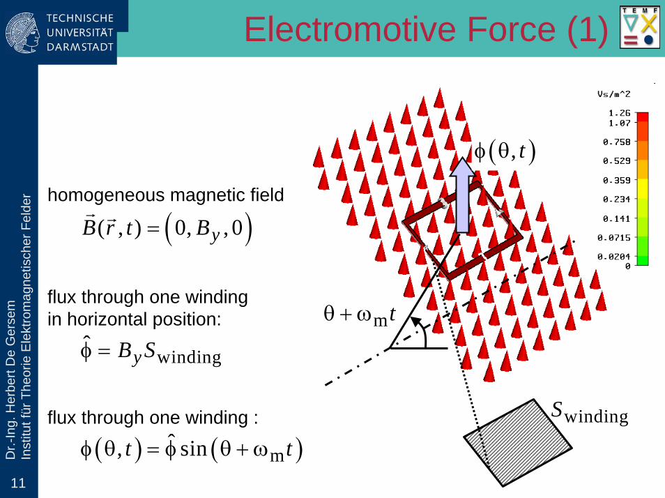
rElectromotive Force (1)
( ) ( )mˆ, sinφ θ = φ θ + ωt t
( ),φ θ t
mθ + ω t
flux through one winding :
( )( , ) 0, , 0=r r
yB r t B
flux through one windingin horizontal position:
windingφ̂ = yB S
homogeneous magnetic field
windingS
12
Dr.-
Ing.
Her
bert
De
Ger
sem
Inst
itut f
ür T
heor
ie E
lekt
rom
agne
tisch
er F
elde
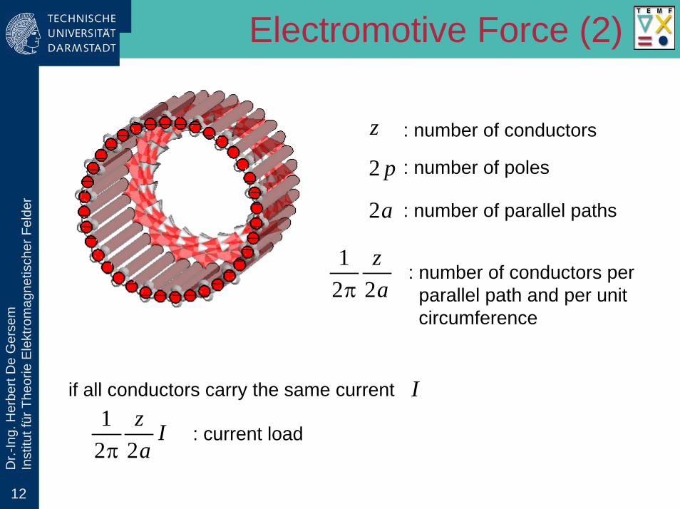
rElectromotive Force (2)
z : number of conductors
2 p : number of poles
2a : number of parallel paths
12 2π
za
: number of conductors perparallel path and per unitcircumference
if all conductors carry the same current
: current load1
2 2πz Ia
I
13
Dr.-
Ing.
Her
bert
De
Ger
sem
Inst
itut f
ür T
heor
ie E
lekt
rom
agne
tisch
er F
elde
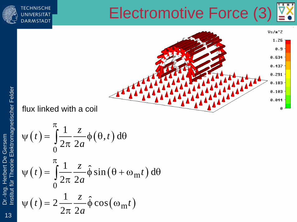
rElectromotive Force (3)
flux linked with a coil
( ) ( )0
1 , d2 2
πψ = φ θ θ
π∫zt ta
( ) ( )m0
1 ˆ sin d2 2
πψ = φ θ + ω θ
π∫zt ta
( ) ( )m1 ˆ2 cos
2 2ψ = φ ω
πzt ta
14
Dr.-
Ing.
Her
bert
De
Ger
sem
Inst
itut f
ür T
heor
ie E
lekt
rom
agne
tisch
er F
elde
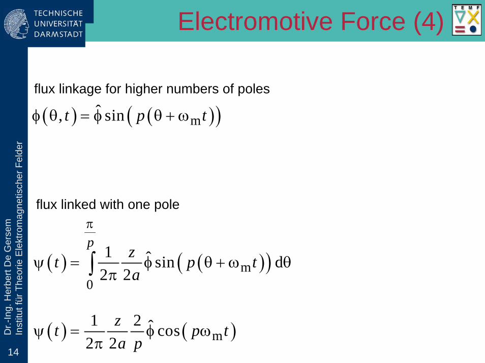
rElectromotive Force (4)
( ) ( )( )mˆ, sinφ θ = φ θ + ωt p t
flux linkage for higher numbers of poles
flux linked with one pole
( ) ( )( )m0
1 ˆ sin d2 2
π
ψ = φ θ + ω θπ∫
p zt p ta
( ) ( )m1 2 ˆ cos
2 2ψ = φ ω
πzt p ta p

15
Dr.-
Ing.
Her
bert
De
Ger
sem
Inst
itut f
ür T
heor
ie E
lekt
rom
agne
tisch
er F
elde
rElectromotive Force (5)
electromotive force for 1 pole
poleddψ
= −Et
( )pole m m1 2 ˆ sin
2 2= φ ω ω
πzE p p ta p
after commutation
pole ˆˆ 22
= φzE na
pole2 ˆˆ2
= = φpE pE z na
for all poles (connected in series)

16
Dr.-
Ing.
Her
bert
De
Ger
sem
Inst
itut f
ür T
heor
ie E
lekt
rom
agne
tisch
er F
elde
r
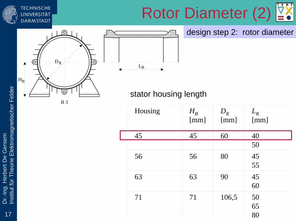
design step 2: rotor diameter
Rotor Diameter (1)
22 δ= φ
pE z na
δ δ δφ = B S
rtrt2δ = βl
DS
rtrt2 2
2
=π
I zA Da
rtrt rtδ
=β πl
E IDB A n p
electromotive force
air-gap flux
magnetic active area
current load
rotor diameter
17
Dr.-
Ing.
Her
bert
De
Ger
sem
Inst
itut f
ür T
heor
ie E
lekt
rom
agne
tisch
er F
elde
r
DRLR
B 3
HB
design step 2: rotor diameter
Rotor Diameter (2)
Housing HB[mm]
DR[mm]
LR[mm]
45 45 60 4050
56 56 80 4555
63 63 90 4560
71 71 106,5 506580
stator housing length

18
Dr.-
Ing.
Her
bert
De
Ger
sem
Inst
itut f
ür T
heor
ie E
lekt
rom
agne
tisch
er F
elde
r
design step 2: rotor diameter
Rotor Diameter (3)
standardized rotor diameter
AD
DA[mm]
3030,33131,353232,232,532,73333,233,53434,53535,33636,236,436,53737,538,63939,239,539,7
4040,240,540,84141,241,441,841,94242,242,542,64343,543,64444,54545,245,74646,446,546,94747,14848,248,854949,249,4
5050,250,450,750,951,251,551,85252,252,452,65353,45454,254,55555,4565757,257,557,65858,255959,359,7
6060,260,461,161,561,856262,262,462,56363,656464,46565,265,465,565,7666767,567,86868,268,368,568,768,869,569,7
7070,270,5717272,57373,473,57474,274,57575,575,87676,276,47777,57878,578,679,379,5
8080,380,680,88181,58282,582,88383,283,38484,384,58585,185,2585,48686,486,88787,758888,38989,389,589,889,9
9090,3919292,292,492,7939494,294,494,89595,596,29797,79899,2
100100,2100,5100,9101102103103,7104104,5105106106,2106,5108109109,5

19
Dr.-
Ing.
Her
bert
De
Ger
sem
Inst
itut f
ür T
heor
ie E
lekt
rom
agne
tisch
er F
elde
rDesign Steps
1. current and electromotive force2. rotor diameter3. cross-sectional areas of conductors and slots4. check resistance and temperature5. choice of the magnet segments6. check saturation

20
Dr.-
Ing.
Her
bert
De
Ger
sem
Inst
itut f
ür T
heor
ie E
lekt
rom
agne
tisch
er F
elde
r
design step 3: cross-sectional areas of conductors and slots
Rotor Diameter (3)
wireJ : maximal allowed current density
wirewire
12
=ISa J
: cross-section of a wire
wire wire4
=π
d S : wire diameter oslot
h1r1
r2
h α
b
Sslot
choose standard wire diameter
slot wire slot0.4 0.5≤ ≤zS S SN
choose slot such that
a)
slot wire>o db)

21
Dr.-
Ing.
Her
bert
De
Ger
sem
Inst
itut f
ür T
heor
ie E
lekt
rom
agne
tisch
er F
elde
rDesign Steps
1. current and electromotive force2. rotor diameter3. cross-sectional areas of conductors and slots4. check resistance and temperature5. choice of the magnet segments6. check saturation

22
Dr.-
Ing.
Her
bert
De
Ger
sem
Inst
itut f
ür T
heor
ie E
lekt
rom
agne
tisch
er F
elde
rResistance
design step 4: check resistance and temperature
rtturn rt
1.33= +l l
Dp
: length of a half a turn
( )( )oturn
path CuCu,20 Cwire1 20
2= ρ + α −
lzR Ta S
: resistance of one path
rt path1
2=R R
a: armature resistance
2Joule rt=P R I : Joule losses

23
Dr.-
Ing.
Her
bert
De
Ger
sem
Inst
itut f
ür T
heor
ie E
lekt
rom
agne
tisch
er F
elde
rTemperature Increase (1)
0 500 1000 1500 2000 2500 3000 3500
10
20
30
40
50∆T [°C]
PJoule / Srt [W/m2] Joule losses per unit rotor surface
tem
pera
ture
incr
ease
design step 4: check resistance and temperature
environment= + ∆T T T : rotor temperature
2rt
rt rt rt 22
⎛ ⎞= π + π ⎜ ⎟⎝ ⎠
lDS D : rotor surface

24
Dr.-
Ing.
Her
bert
De
Ger
sem
Inst
itut f
ür T
heor
ie E
lekt
rom
agne
tisch
er F
elde
r
design step 4: check resistance and temperature
Temperature Increase (2)
temperature increases
→ resistance increases
→ Joule losses increase (under constant current)
→ temperature increases
iteration needed
possibly unstable iteration, convergence ?
check resistive voltage drop
rt ≤ −R I U E
25
Dr.-
Ing.
Her
bert
De
Ger
sem
Inst
itut f
ür T
heor
ie E
lekt
rom
agne
tisch
er F
elde
rDesign Steps
1. current and electromotive force2. rotor diameter3. cross-sectional areas of conductors and slots4. check resistance and temperature5. choice of the magnet segments6. check saturation

26
Dr.-
Ing.
Her
bert
De
Ger
sem
Inst
itut f
ür T
heor
ie E
lekt
rom
agne
tisch
er F
elde
r
design step 5: choice of the magnet segments
Permanent-Magnet Material
Mc Hc Hc *
Br
B [T] J [T]
B = µ0 H
H [A/m] HM
BM
HAR max

27
Dr.-
Ing.
Her
bert
De
Ger
sem
Inst
itut f
ür T
heor
ie E
lekt
rom
agne
tisch
er F
elde
r
design step 5: choice of the magnet segments
Temperature Dependence
( )( )rr r,25 C 1 25= + α −o BB B T
( )( )cc c,25 C 1 25= + α −o HH H T
( )( )crc c,25 C 1 25= + α −o MM M T

28
Dr.-
Ing.
Her
bert
De
Ger
sem
Inst
itut f
ür T
heor
ie E
lekt
rom
agne
tisch
er F
elde
r
design step 5: choice of the magnet segments
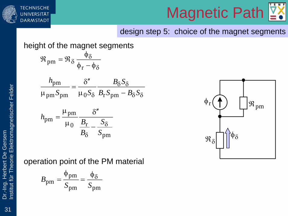
Magnetic Path
rφ
δℜ
rt2
ℜ
pmℜ
st / 2ℜ
rφ
δℜ
rt2
ℜ
pmℜ
st / 2ℜ
rφ
δℜ
rt2
ℜ
pmℜ
st / 2ℜ
rφ
δℜ
pmℜ
δφ
( )pm pm 0δ δ δℜ φ + ℜ φ − φ =

29
Dr.-
Ing.
Her
bert
De
Ger
sem
Inst
itut f
ür T
heor
ie E
lekt
rom
agne
tisch
er F
elde
r
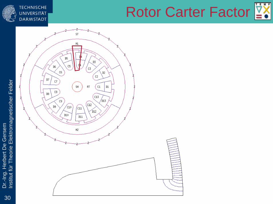
design step 5: choice of the magnet segments
Magnetic Path
( )pm r 0δ δ δℜ φ + ℜ φ − φ =
rφ
δℜ
pmℜ
δφ
r r pmφ = B S
pmpm
pm pm
1ℜ =
µ
hS
0
1δ
δ
′′δℜ =
µ S
Fe c,st c,rt′′δ = δk k k
factor accounting for magnetic voltage drop in iron partsCarter factor for the stator
Carter factor for the rotor
pm pm pm= β lS r
rtrt2δ = β l
DS
rtpm 2
= + δDr
30
Dr.-
Ing.
Her
bert
De
Ger
sem
Inst
itut f
ür T
heor
ie E
lekt
rom
agne
tisch
er F
elde
rRotor Carter Factor
31
Dr.-
Ing.
Her
bert
De
Ger
sem
Inst
itut f
ür T
heor
ie E
lekt
rom
agne
tisch
er F
elde
r
design step 5: choice of the magnet segments
Magnetic Path
pmr
δδ
δ
φℜ = ℜ
φ − φ
height of the magnet segments
pm
pm pm 0 r pm
δ δ
δ δ δ
′′δ=
µ µ −
h B SS S B S B S
rφ
δℜ
pmℜ
δφ
pmpm
r0pm
δ
δ
µ ′′δ=
µ −h SB
B S
operation point of the PM materialpm
pmpm pm
δφ φ= =B
S S
32
Dr.-
Ing.
Her
bert
De
Ger
sem
Inst
itut f
ür T
heor
ie E
lekt
rom
agne
tisch
er F
elde
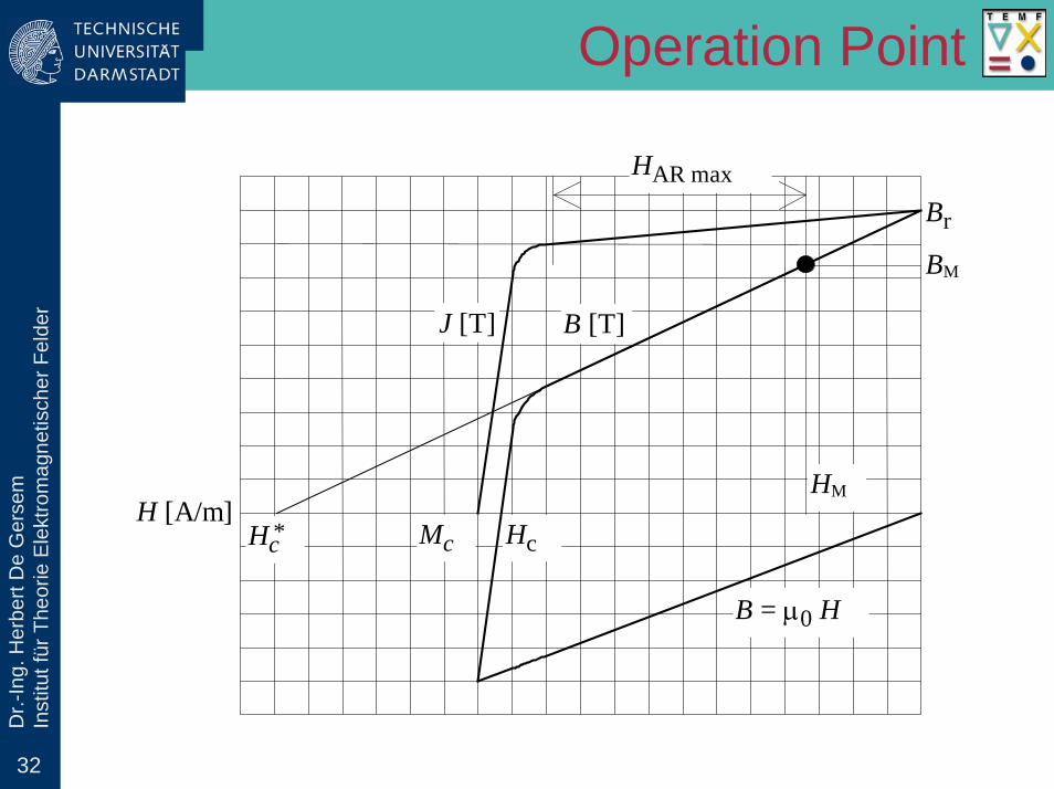
rOperation Point
Mc Hc Hc *
Br
B [T] J [T]
B = µ0 H
H [A/m] HM
BM
HAR max

33
Dr.-
Ing.
Her
bert
De
Ger
sem
Inst
itut f
ür T
heor
ie E
lekt
rom
agne
tisch
er F
elde
rArmature Reaction (1)
worstcasescenario
′′δ
δℜ%pmℜ%
2 2βπ
zIa pmh
path%S
δℜ%pmℜ%
2 2βπ
zIa
pmpm
pm pathℜ =
µ%
%
hS
0 pathδ
′′δℜ =
µ%
%S
armr
H
armφ
armφ

34
Dr.-
Ing.
Her
bert
De
Ger
sem
Inst
itut f
ür T
heor
ie E
lekt
rom
agne
tisch
er F
elde
rArmature Reaction (2)
worst case scenario
armpm
12 2 2 2 δ
βφ =
π ℜ + ℜ% %zIa
′′δ
δℜ%pmℜ%
2 2βπ
zIa pmh
path%S
δℜ%pmℜ%
2 2βπ
zIa
armr
H
armφ
armφ
( )armpm rev
12 2 2
β=
π ′′+ µ δ
zIHa h
arm c pm≤ γ −H M M
check
0.83γ =empirical factor

35
Dr.-
Ing.
Her
bert
De
Ger
sem
Inst
itut f
ür T
heor
ie E
lekt
rom
agne
tisch
er F
elde
rDesign Steps
1. current and electromotive force2. rotor diameter3. cross-sectional areas of conductors and slots4. check resistance and temperature5. choice of the magnet segments6. check saturation

36
Dr.-
Ing.
Her
bert
De
Ger
sem
Inst
itut f
ür T
heor
ie E
lekt
rom
agne
tisch
er F
elde
rRotor Teeth
design step 6: check saturation
concentration factor
teethc
stack teeth
11
π=
− γDf
Nb
magnetic flux density in the teeth
teeth c δ=B f B

37
Dr.-
Ing.
Her
bert
De
Ger
sem
Inst
itut f
ür T
heor
ie E
lekt
rom
agne
tisch
er F
elde
rStator Yoke
design step 6: check saturation
magnetic cross-section of the stator yoke
( )yoke stack st yoke1= − γ lS h
yokeyoke
12δφ
=BS
magnetic flux density in the stator yoke

38
Dr.-
Ing.
Her
bert
De
Ger
sem
Inst
itut f
ür T
heor
ie E
lekt
rom
agne
tisch
er F
elde
rDesign Steps
1. current and electromotive forcepower balance (experience values)
2. rotor diameterapplication of Faraday-Lenz
3. cross-sectional areas of conductors and slotslimitation on current density
4. check resistance and temperaturelimitation on voltage drop and temperature
5. choice of the magnet segmentsapplication of Ampère
6. check saturationlimitation on magnetic flux density
39
Dr.-
Ing.
Her
bert
De
Ger
sem
Inst
itut f
ür T
heor
ie E
lekt
rom
agne
tisch
er F
elde
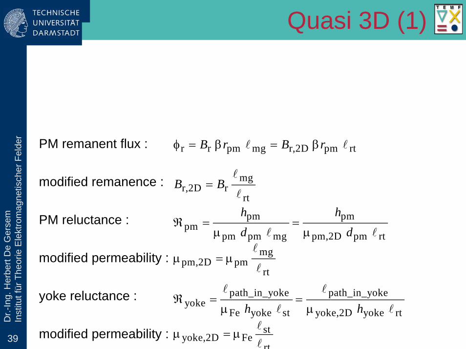
rQuasi 3D (1)
PM remanent flux : r r pm mg r,2D pm rtφ = β = βl lB r B r
path_in_yoke path_in_yokeyoke
Fe yoke st yoke,2D yoke rtℜ = =
µ µ
l l
l lh hst
yoke,2D Fert
µ = µl
l
yoke reluctance :
modified permeability :
modified remanence : mgr,2D r
rt=
l
lB B
pm pmpm
pm pm mg pm,2D pm rtℜ = =
µ µl l
h hd d
mgpm,2D pm
rtµ = µ
l
l
PM reluctance :
modified permeability :
40
Dr.-
Ing.
Her
bert
De
Ger
sem
Inst
itut f
ür T
heor
ie E
lekt
rom
agne
tisch
er F
elde
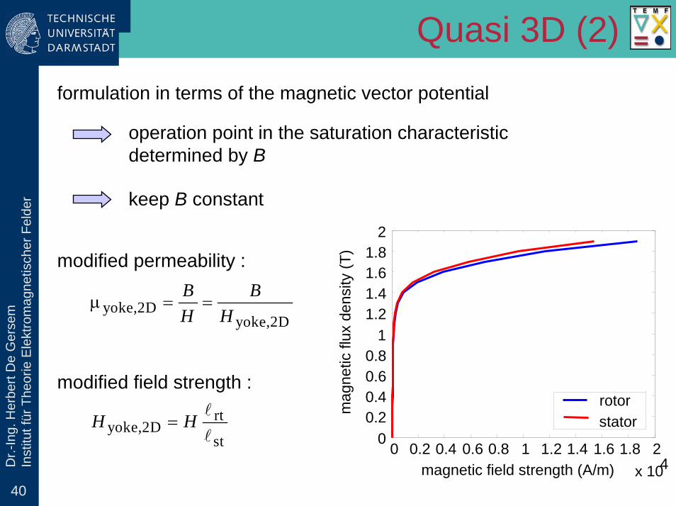
rQuasi 3D (2)
formulation in terms of the magnetic vector potential
operation point in the saturation characteristicdetermined by B
keep B constant
0 0.2 0.4 0.6 0.8 1 1.2 1.4 1.6 1.8 2x 10⁴
00.20.40.60.8
11.21.41.61.8
2
magnetic field strength (A/m)
mag
netic
flux
den
sity
(T)
rotorstator
modified permeability :
yoke,2Dyoke,2D
µ = =B BH H
rtyoke,2D
st=
l
lH H
modified field strength :
41
Dr.-
Ing.
Her
bert
De
Ger
sem
Inst
itut f
ür T
heor
ie E
lekt
rom
agne
tisch
er F
elde
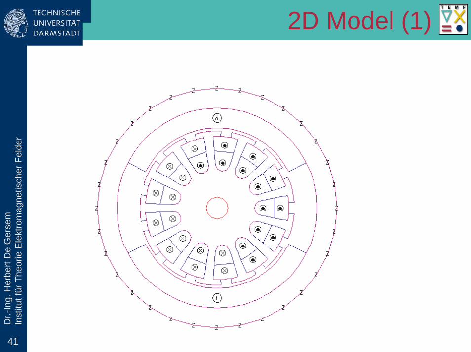
r2D Model (1)

42
Dr.-
Ing.
Her
bert
De
Ger
sem
Inst
itut f
ür T
heor
ie E
lekt
rom
agne
tisch
er F
elde
r2D Model (2)
without armature reaction with armature reaction
43
Dr.-
Ing.
Her
bert
De
Ger
sem
Inst
itut f
ür T
heor
ie E
lekt
rom
agne
tisch
er F
elde
r
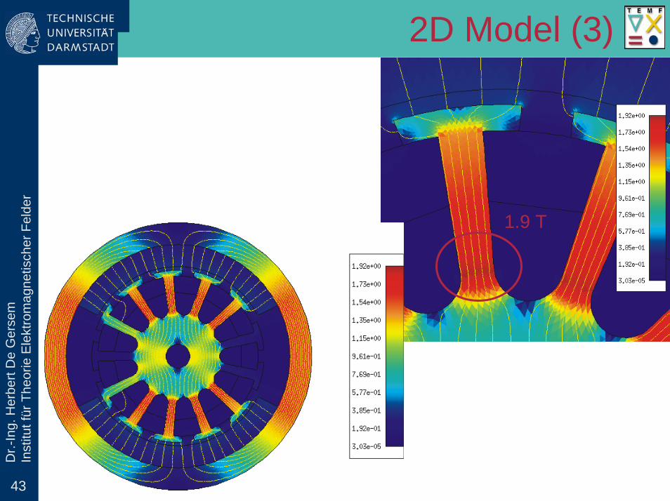
1.9 T
2D Model (3)

44
Dr.-
Ing.
Her
bert
De
Ger
sem
Inst
itut f
ür T
heor
ie E
lekt
rom
agne
tisch
er F
elde
r3D Model

Technische Universität Darmstadt, Fachbereich Elektrotechnik und InformationstechnikSchloßgartenstr. 8, 64289 Darmstadt, Germany - URL: www.TEMF.de
Dr.-
Ing.
Her
bert
De
Ger
sem
In
stitu
t für
The
orie
Ele
ktro
mag
netis
cher
Fel
der
Lecture Series
Finite-Element Electrical Machine Simulation
http://www.ew.e-technik.tu-darmstadt.de/FOR575NEXT LECTURE : THURSDAY May 18th
OTHER ROOM (see website)
Dr.-Ing. Herbert De Gersemsummer semester 2006
Institut für Theorie Elektromagnetischer Felder