finite element simulation of castellated beam by
TRANSCRIPT

PERPUSTAKAAN UMP
1111111111111111111111111111111111111 0000092774
FINITE ELEMENT SIMULATION OF CASTELLATED BEAM BY USING
CIVILFEM WITH ANSYS SOFTWARE
TAN POH AUN
A thesis submitted in fulfilment of the requirements for the award of the degree of
B. ENG (HONS.) CIVIL ENGINEERING
Faculty Of Civil Engineering and Earth Resources
UNIVERISITI MALAYSIA PAHANG
JUNE 2014

V
ABSTRACT
Nowadays in the construction of modem buildings, it is necessary to accommodate pipes and ducts necessary services, such as air conditioning, water supply, sewerage, electricity, computer networks and telephone networks. Finite element method is the leading technique for analysing the behaviour of structures when subjected to a variety of loads. In order to minimize storey height and achieve economic requirements most of industrial building using castellated beam. Besides that, the intention of castellated beam used in the steel structure is without any additional material also will increase the beam's web depth as well as the strength of the beam. The finite element results are compared in term of load deflection curve, pure bending, shear, and lateral torsional buckling, showing a good agreement. Hence, from the results this study was conducted that finite element analysis is able to give a similar result as the analytical results. Moreover, this results presents the castellated beam results by using the ANSYS software. The objective of this study is to obtain the maximum deflection, maximum von mises strain, maximum von mises stress by Probabilistic Design System (PDS)

Vi
ABSTRAK
Kini dalam pembinaan bangunan-bangunan moden, adalah perlu untuk menampung paip dan saluran perkhidmatan yang diperlukan, seperti penyaman udara, bekalan air, pembetungan, elektrik, rangkaian komputer dan rangkaian telefon. Kaedah unsur terhingga adalah teknik utama untuk menganalisis kelakuan struktur apabila dikenakan pelbagai beban. Dalam usaha untuk mengurangkan ketinggian tingkat idan mencapai keperluan ekonomi yang paling bangunan industri yang mënggunakan rasuk istana. Selain itu, niat untuk rasuk istana digunakan dalam struktur keluli adalah tanpa apa-apa bahan tambahan juga akan meningkatkan kedalaman web rasuk dan juga kekuatan rasuk. Keputusan unsur terhingga dibandingkan dari segi lengkung beban pesongan, lenturan tulen, ricih, dan lengkokan kilasan sisi, menunjukkan penjanjian yang baik. Oleh itu, daripada hasil kajian mi telah dijalankan bahawa analisis unsur terhingga mampu memberikan hasil yang sama seperti hasil analisis. Lebih-lebih lagi, mi menyebabkan membentangkan keputusan rasuk istana dengan menggunakan perisian ANSYS itu. Objektif kajian mi adalah untuk mendapatkan pesongan maksimum, maksimum von Mises terikan, maksimum von Mises tekanan dengan Rekabentuk Sistem berkebarangkalian (PDS).

vii
TABLE OF CONTENTS
SUPERVISOR'S DECLARATION .................................................................................... ii
STUDENT'S DECLARATIOIN........................................................................................iii
ACKNOWLEDGEMENT .......................................... . .......................... . ............................. iv
ABSTRACT ........................................................................................................................... v
A_I3 ST11i1(............................................................................................................................vi
LISTOF FIGURES .................................. ............................................................................
LIST OF TABLES ................................................ ........ ..................................................... xiii
CHAPTER 1: INTRODUCTION
1 .1 General ......................................................................................................................... 1
1 .2 Problem statement ............................................... . ........................................................ 2
1.3 Objectives of research..................................................................................................2
1 .4 Scope of study..............................................................................................................3
1 .5 Expected Outcome .......................................................................................................3
CHAPTER 2: LITERATURE REVIE\
2.1 Introduction..................................................................................................................2
2.2 Castellated Beam Analysis ............................................................ ............................... 2 2.3 Finite Element Method (FEM).....................................................................................6 2.4 ANSYS.........................................................................................................................8
CHAPTER 3: METHODOLOGY
3.1 Introduction.................................................................................................................. 5 3.2 Method use to Analyse Structure...............................................................................12 3.3 Design process............................................................................................................13

viii
3.3.1 AN.SYS Preprocessor: Defining the problem ................................ . .................. 13
3.12 ANSYS Solution Processor: Assigning loads and solving............................. 13
3.3.3 ANSYS Post-processing: Viewing the results ................................................. 14
3.4 ANSYS Preprocessor. Process ...... . .............................................................................. 14
3.4.1 Defining an Analysis Title.............................................................................. 14
3.4.2 Defining Element Type and.Real Constants................................................... 15
3.4.3 Defining Material Properties ........................................................................... 16
3.4.4 Creating the Model Geometry ........................................................................ 17
3.4.5 Meshing .......................................................................................................... 19
3.5 ANSYS Solution Processor .............................................................................. .... . .... .20
3.5.1 Define Analysis Type ...................................................................................... 20
3.5.2 Boundary Condition........................................................................................ 22
3.5.3 Applying Load ................................................................................................ 23
3.5.4 Solving .......................... . ................................................................................. 23
3.6 ANSYS Post-Processing............................................................................................ 24
3.6.1 Deformed Shape ............................................................................................. 24
3.6.2 Displacement ................................................................................................... 25
3.7 Probabilistic Design System (PDS) .................................................................... ......... 26
CHAPTER 4: RESULT ANALYSIS AND DISCUSSION
4.0 Introduction................................................................................................................ 27
4.2 Probabilistic Model Information................................................................................ 28
4.2.1 Random Input Variables................................................................................. 28
4.2.2 Correlations..................................................................................................... 32
4.2.3 Probabilistic Analysis Summary..................................................................... 32
4.2.4 Probabilistic Analysis Results ........................................................................ 33
4.4 Sample History Plots.................................................................................................. 34
4.4.1 Sampled Values for Output Parameter MAXIMUM DEFLECTION............ 35
4.4.2 Sampled Value for Output Parameter MAX DEFLECTION........................ 37
4.4.3 Sampled Values for Output Parameter MAXVONMISESSTRESS .............. 39

ix
4.4.4 Sampled Values for Output Parameter MAX VONMISESSTRAIN.............. 41
4.5 Histogram Plots........................................................................................................... 43
4.5.1 Histogram of Input Variables .......................................................................... 43
4.5.2 Histogram of Output Parameters .................................................................... 46
4.6 Cumulative Distribution Function Plots..................................................................... 48
4.6.1 Cumulative Distribution Funôtion of Input Variables ..................................... 49
4.6.2 Cumulative Distribution Function of Random Output Parameters ................ 52
4.7 Sensitivity Plots ........................................................................................................... 56
CHAPTER 5: CONCLUSION AND RECOMMENDATION
5.1 Conclusion ................................................................................................................... 60
5.2 Recommendation........................................................................................................61
REFERENCES .................................................................................................................... 62
APPENDIX A...................................................................................................................... 64
APPENDIXB ...................................................................................................................... 71

x
LIST OF FIGURES
Figure 21: .Vierendeel Truss A±ialogy 5
Figure 2.2: Mathematical Formulation of Castellated Beam 6
Figure 2.3: Standard Castellated Section 6
Figure 2.4: Linear algebraic equations . 7
Figure 2.5: Non-composite finite element model 7
Figure 2.6: Castellated Beam model . . . 8
Figure 2.7: Typical Finite Element Mesh for a Castellated Beam ............................................ 9
Figure 2.8: Applying load on castellated beam . 9
Figure 3.1: Flow chart of the modelling process 12
Figure 3.2: Change title steps 15
Figure 3.3: Change title window 15
Figure 3.4: Definition of element types to be used 16
Figure 3.5: Selection of element types from the library . 16
Figure 3.6: Define Material Model Jiehaviour 17
Figure 3.7: Linear isotopic material properties .17
Figure 3.8: Create key point process 17
Figure 3.9: Area reflect in Y-Z Plane 18
Figure 3.10: Model line to area 19
Figure 3.11: Global Element Sizes 19
Figure Figure 3.12: Model Meshing 20
Figure 3.13: Dialog boxes for selecting the type pf analysis for structural 20
Figure 3.14: Solution Controls dialog box .21
Figure 3.15: Boundary Condition for Support 22
Figure 3.16: Applying Load on Castellated Beam . . 23
Figure 3.17: ANSYS Responds .. 24
Figure 3.18: Deformed Shape 24
Figure 3.19: Deflection value in nodal solution 25
Figure 4.1: Model Geometry and Finite Element Mesh 28 Figure 4.2: PDF & CDF of Input Random Variable FORCE_1 29

xi
Figure 43: PDF & CDF of Input Random Variable FORCE -2 30
Figure 4.4: PDF & CDF of Input Random Variable HEAT 30
Figure 4.5: PDF & CDF of Input Random Variable HOLE RADIUS 31
Figure 4.6: PDF & CDF of Input Random Variable 1
Figure 4.7: PDF & CDF of Input Random Variable POISSON RATIO 32
Figure 4.8: Sampled Values for Output Parameter MAXIMUM
Figure 4.9: Mean Values for Output Parameter MAXIMUM DEFLECTION 36
Figure 4.10: Standard Deviation Values for Output Parameter MAXIMUM DEFLECTION
36
Figure 4.11: Sampled Values for Output Parameter MAX DEFLECTION 37
Figure 4.12: Standard Deviation Values for Output Parameter MAX—DEFLECTION
38
Figure 4.13: Mean Values for Output Parameter MAX _ DEFLECTION 38
Figure 4.14: Sampled Values for Output Parameter MAXVONMISES STRESS 39
Figure 4.15: Standard Deviation Values for Output Parameter MAXVONMISESSTRESS
40
Figure 4.16: Mean Values for Output Parameter MAXVONMISESSTRESS 40
Figure 4.17: Sampled Values for Output Parameter MAX VONMISESSTRA1N-- 41
Figure 4.18: Standard Deviation Values for Output Parameter MAX VONMISES STRAIN
------------------------------------------------------------------------------------------------------------------- 42
Figure 4.19: Mean Values for Output Parameter MAXVONMISES STRAIN 42
Figure 4.20: Histogram of Input Variable FORCE_1 43
Figure 4.21: Histogram of Input Variable FORCE_2 44
Figure 4.22: Histogram of Input Variable HEAT 44
Figure 4.23: Histogram of Input Variable HOLE_RADIUS 45
Figure 4.24 Histogram of Input Variable ELASTIC _ MODULUS 45
Figure 4.25: Histogram of Input Variable POISSON_RATIO 46 Figure 4.26: Histogram of MAXIMUM DEFLECTION 46Figure 4.27: Histogram of MAX DEFLECTION
Figure 4.28: Histogram of MAXVONMISESSTRESS
Figure 4.29: Histogram Of MAXVONMISESSTRAIN 48

xli
Figure 4.30: CDF of input variable FORCE_i .49
Figure 4.31: CDF of input variable FORCE_2 49
Figure 4.32: CDF of input variable HEAT 50
Figure 4.33.: CDF of input variable HOLE RADIUS . 50
Figure 4.34: CDF of input variable ELASTIC MODULUS . 51
Figure 4.35: CDF of input variable POISSON —RATIO . 51
Figure 4.36: CDF of output parameter MAXIMUM DEFLECTION 52
Figure 4.37: CDF of output parameter MAX—DEFLECTION ............................................... 53
Figure 4.38: CDF of output parameter MAXVONMISESSTRESS 54
Figure 4.39: CDF of output parameter MAXVONMISESSTRAIN55
Figure 4.40: Sensitivity plots for MAXIMUM DEFLECTION56
Figure 4.41: Sensitivity plots for MAX_DEFLECTION 57
Figure 4.42: Sensitivity plots for MAXVONMISESSTRESS58
Figure 4.43: Sensitivity plots for MAXVONMISESSTRAIN 59

xlii
LIST OF TABLES
Table 1.1: Properties of castellated be 3
Table 3.1: Coordinate of keypoint - 18
Table 3.2: Solution Controls Options - 21
Table 4.1: Random Input Variable Specifications ................................................................... 29
Table 4.2: Specification for Monte Carlo Simulation Analysis 32
Table 4.3: Result Set - Statics of the Random Input Variables 33
Table 4.4: Results Set - Statics of the Random Output Parameters 34

CHAPTER 1
INTRODUCTION
1.1 General
In the construction of modern buildings, it is necessary to accommodate pipes and
ducts necessary services, such as air conditioning, water supply, sewerage, electricity,
computer networks and telephone networks,: in order to minimize storey height and achieve
economic requirements. Usually, these pipes and tubes are placed under the beam soffit, for
aesthetic reasons, covered ceiling, thus creating a corner. (Chen, et al., 2008). Due to web
openings presence leads to change of the stress distribution in the beam. The highest stress
may or may not occur in the mid span. The changes of beam stress are depending on the
shape, size and position of the opening (Akwãsi Manu Assenso ,Antwi, 2012).
Besides that, the intention of castellated beam used in the steel structure is without
any additional material also will increase the beam's web depth as well as the strength of the
beam. This study aim to identify the simulation of castellated beam with different loading
applied. Finite element method is the leading technique for analysing the behaviour of
structures when subjected to a variety of loads. The finite element results are compared in
term of load deflection curve, pure bending, shear, and lateral torsional buckling, showing a
good agreement (Soltani, et al., 2012).

2
1.2 Problem statement
In recent years, researches had been done on different types of opening with respect
to T-beams, precast beams, steel beams and deep beams but circular beams are the ones that
having little information on it. Therefore, it is essential that having some experimental
construction in the lab which is vital in presenting the performance of opening in the beams;
opening on beam web is more than half of its depth that corresponded to the restricted detail
of typical rectangular beams (Saksena & Patel, 2013).
There were several experimental and analytical studies that have been use in
analysing the various structural aspects of castellated beam with the effect of web openings,
with different modes of failures and the depth of web opening increasing with the effect of
deflection (Wakehaure, et al., 2012). As a result, six different modes of failure have been
reported by Kerdal and Nethercot in year 1984 (Kerdal & Nethercot, 1984). The castellated
beam with six possible failure modes such as flexure mechanism, lateral torsional buckling,
Vierendeel mechanism, rupture in welding joint, shear of web post, and compression
buckling (Wakchaure, et al., 2012).
Besides that, finite element method is very widely used for solving engineering
problem. It give difficulties to engineering if without software calculation cause the manual
calculation took long time to calculate and sometime will make mistake.
1.3 Objectives of research
1. To obtain the maximum deflection, max von mises strain, max von mises stress by
Probabilistic Design System (PDS).
2. To analyse the reaction forces, deformation, deflection, axial stress and heat transfer.

I
1.4 Scope of study
1. To identify the effect of the various load acting on the castellated beam by using
ANSYS software.
2. ANSYS 12.0 + Civi1FEM 12.0 software is to obtain analysis result and compare with
finite element method (FEM).
Table 1.1: Properties of castellated beam.
Length of the beam 3 in
Steel Grade S275
Poisson Ratio, v 0.3
Elastic Modulus, E 210E+09
Type of Steel IPE 240
Type of opening Hexagonal Opening
Number of opening 15
Radius 0.07 in
1st Support L/6
2nd Support L - L/6
1st Point Load L/3
Point Load L—L/3
1.5 Expected Outcome
This paper is to obtain the result of simulation castellated beam by using ANSYS
Software and compare the result with finite element method (FEM). Moreover, this study can
proved that finite element formulation gives more accurate results in the global behaviour of
the beam system.

CHAPTER 2
LITERATURE REVIEW
2.1 Introduction
In recent years there are continually growing rapidly by using steel structure in the
construction industry across world. Castellated beam is one type of the steel structure's beam,
by increasing the depth of beam also will increase the strength of beam without additional
material (Billy Milligan, 2001). This chapter is to describe the model using finite element
software package ANSYS +Civ11FEM in analysing the behaviour of castellated steel beams
having an I-shaped cross-section.
2.2 Castellated Beam Analysis
There are several method were used to analyse the castellated beam. Early methods
in analysing the castellated beam was calculation of section properties excluded the web and
flange but analyses the compression flange as a strut. In 1982, Kerdal and Nethercot
discovered that the section properties at the middle of castellated beam or hole must be
calculated. Besides that, they also found that the design for castellated beams can be derived
from the equation for the behaviour of hot-rolled sections (Kerdal & Nethercot, 1982).
Common method used to analyse the castellated beam is Vjerendeel analysis (Billy Milligan, 2001).

5
This method is to consider the longitudinal stresses due to bending and the local
bending from shear force which can increase the stresses in the I-section (Srimanit & Dast,
1977).
Figure 2.1: Vierendeel Truss Analogy
In 1984, Kerdal and Nethercot realized that the properties of lateral-torsional buckling
were found in all the ultimate strength tests (Kerdal & Nethercot, 1984). They also found out
that the castellated beams had six failure modes;
1. Formation of a Vierendeel mechanism
2. Lateral-torsional buckling of the web post
3. Rupture of the welded joint
4. Lateral-torsional buckling of the entire span
5. Web post buckling
6. Formation of a flexure mechanism
Any six failure modes were usually involved in the combination of test specimens.
Providing the adequate lateral bracing was to evaluate the failure modes other than lateral-
torsional buckling in the test specimens and the beams would reach their full-strength (Kerdal
& Nethercot, 1984). Due to lack of lateral support to the compression flange, non-composite
castellated beams are more susceptible to lateral-torsional buckling than composite beams.
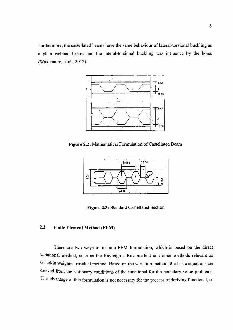
Furthermore, the castellated beams have the same behaviour of lateral-torsional buckling as
a plain webbed beams and the lateral-torsional buckling was influence by the holes
(Wakchaure, et al., 2012).
\lVd
Figure 2.2: Mathematical Formulation of Castellated Beam
Figure 2.3: Standard Castellated Section
2.3 Finite Element Method (FEM)
There are two ways to include FEM formulation, which is based on the direct
variational method, such as the Rayleigh - Ritz method and other methods relevant as
Galerkin weighted residual method. Based on the variation method, the basic equations are
derived from the stationary conditions of the functional for the boundary-value problems.
The advantage of this formulation is not necessary for the process of deriving functional, so

7
it is easy to analyse based on the finite element method (FEM) for the preparation of the
weighted residuals.
In order to define the building design response with simulation loading condition,
Finite Element Analysis is a way for different building condition The meaning of element is
the design of model using discrete building blocks which to analyse how the elements
responds to a certain load with each exact equations During the 1950s and 1960s, academic
and industrial researchers were created the finite element method of structural analysis.
[K]tq,j {F
-:--I T f
PNo force] Stiffness matrix
Nodal
Figure 2.4: Linear algebraic equations
The purpose of this study is to manipulate the finite element software package
ANSYS 12.0 programs to simulate the behaviour of castellated be for load deflection plots
and stress-strain plots During 1996, a single web-post in non-composite castellated beams
on the buckling of the web-post has been done by Zaarour and Redwood using FEM (Zaarour
& Redwood, 1996).
Figure 2.5: Non-composite finite element model

8
2.4 ANSYS
ANSYS software is the most advanced package for single- and multi-physics
simulations, providing enhanced tools and features that enable engineers to complete their
work in. an efficient manner. ANSYS includes significant capabilities, expanding
functionality, and integration with almost all CAD drawing software, such as Pro/Engineer,
Aut0CAD, and Sold Edge. In addition, ANSYS has the best-in-class solver technologies, an
integrated coupled physics for complex simulations, integrated meshing technologies
customizable. for physics, and computational fluid dynamics (CFD). ANSYS can solve
problems in structural, thermal, fluid, acoustics, and multi-physics.
In years 2012, Wakchaure and Sagade have done a study which is related to
Castellated Beam using finite element software package ANSYS 14.0 on a three-dimensional
(31)) finite element model (Wakchaure & Sagade, 2012). Besides that, the previous study of
ANSYS has provided information about developing finite element models by Zirakian and
Showkati such as in the form of failure loads, failure modes, load-lateral deflection curves
and load-strain curves (Zirakian & Showkati, 2007).
Figure 2.6: Castellated Beam model

Figure 2.7: Typical Finite Element Mesh for a Castellated Beam
Figure 2.8: Applying load on castellated beam

10
Based on this study, finite element software package ANSYS 12.0 can be categorize into
three group as shown in below:
1. Preprocessing
• Specify title
• Set code
• Set units
• Define material
• Define element type
• Define section
• Define Beam properties
• Define Nodes and Elements
• Save the database
2. Solution
• Apply displacement constraints
• Apply force load
• Solve
3. Post-processing
• Enter the postprocessor and read results
• Plot bending moment
• Plot the bending stress in Y top
• List bending extreme stresses
• Plot bending stress distribution inside the cross-section

CHAPTER 3
METHODOLOGY
3.1 Introduction
This chapter will discuss the method on how to analyse the castellated beam and its
behaviour problem. ANSYS is use to analyse and determine the strength of castellated beam
under different loading applied. In ANSYS 12.0, there are three categorize group which are
preprocessing, solution and post processing. Preprocessing stage consists of the units system,
active code, materials, element types, section, and model geometry definition. For the
solution stage, it consists of the analysis type and its options, apply loads and initiate the
finite element solution whereas at post processing stage consists of reviewing the analysis
results through graphic displays and tabular listings.
12
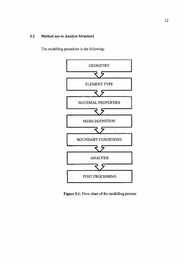
3.2 Method use, to Analyse Structure
The modelling procedure is the following:
GEOMETRY
ELEMENT TYPE
MATERIAL PROPERTIES
MESH DEFINITION
BOUNDARY CONDITIONS
ANALYSIS
POST PROCESSING
Figure 3.1: Flow chart of the modelling process

13'
3.3 Design process
3.3.1 ANSYS Preprocessor: Defining the problem
Model generation is conducted in this processor, which involves material definition,
creation of a solid model, and finally, meshing Important tasks within this processor are
• Specify the title
• Set code and units
• Define material
• Define element type
• Define section
• Define beam & shell properties
• Define nodes and elements
• Mesh the model
3.3.2 ANSYS Solution Processor: Assigning loads and solving
This processor is used for obtaining the , solution for the finite element model that is
generated within the Preprocessor. Important tasks within this processor are:
• Apply displacement constraints
• Apply force load
• Define analysis type and analysis option
• Specify boundary condition
• Obtain solution

14
3.3.3 ANSYS Post-processing: Viewing the results
In this processor, the results at a specific time (if analysis type) is transient) over the
entire or a portion of the model are reviewed. This includes the plotting of contours, vector
displays, deformed shapes, and listings of the results in tabular format. Important tasks within
this processor are:
. Enter the postprocessor and read results
. Plot the deformed shape
• Plot bending stress in Z top fibre
• List bending stress in Z top fibre
3.4 ANSYS Preprocessor Process
A typical Civi1FEM analysis begins with providing data such as the units system,
active code, materials, element types, model, and section geometry definition.
3.4.1 Defining an Analysis Title
Utility Menu > File> Change Title
Which brings up the dialog box shown in Figure 3.2. After entering desired title in
text box, clicking on OK completes the specification of the title. The /TITLE command,
defines a title for the analysis. ANSYS includes the title on all graphics displays and on the
solution output.