fine sun tracker for advanced orbiting solar observatory
TRANSCRIPT
FINE SUN TRACKERFOR
ADVANCED ORBITING SOLAR OBSERVATORY
Clarence CantorSpacecraft Systems and Projects Division
Goddard Space Flight Center/NASAGreenbelt, Maryland
SUMMARY: The analysis and design of a fine sun tracker for theAdvanced Orbiting Solar Observatory are discussed. The tracker pro-vides accurate pointing information in pitch and yaw, permitting pre-cise static and dynamic orientation of the observatory with respectto the sun's apparent disc, in accordance with ground commands. Thetracker uses a servo driven optical slab in each axis to offset theoptiTal null by the required amount. The error signal thus developedin a pair of matched silicon photo-voltaic cells is fed to the obser-vatory control system, to produce the desired orientation in thataxis. The essential features of the tracker design are incorporatedin a breadboard model. The performance of this model verifies theinherent capability of the designpointing accuracy.
INTRODUCTION
This report describes the basicanalysis and design of a fine suntracker for the Advanced OrbitingSolar Observatory (AOSO). One of theprime requirements of the AOSO, as wellas the most critical, is the need forprecise static and dynamic attitudeorientation of the observatory withrespect to the sun's apparent disc, inaccordance with ground commands. Thisrequires the use of a precision suntracker to provide accurate pointinginformation for the AOSO control sys-tem, which can then produce the com-manded attitude orientation in pitchand yaw. A separate inertial refer-ence is used for the required AOSOroll control during this pitch andyaw orientation.
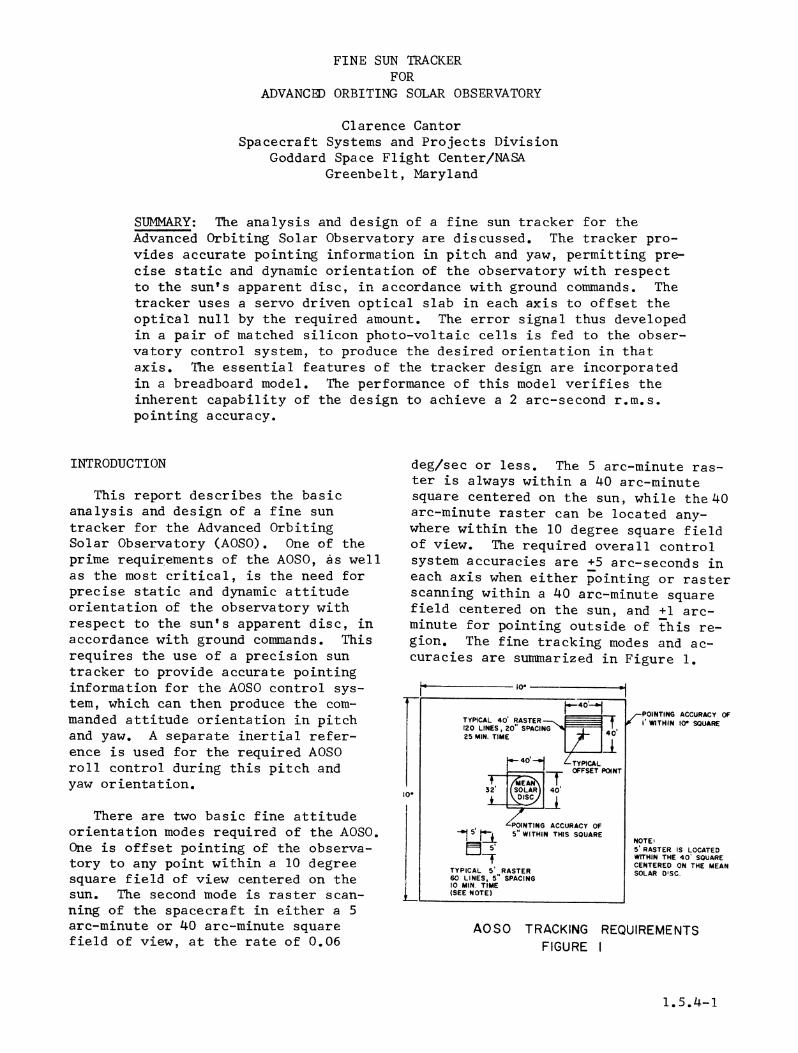
There are two basic fine attitudeorientation modes required of the AOSO.One is offset pointing of the observa-tory to any point within a 10 degreesquare field of view centered on thesun. The second mode is raster scan-ning of the spacecraft in either a 5arc-minute or 40 arc-minute squarefield of view, at the rate of 0. 06
to achieve a 2 arc-second r.m.s.
deg/sec or less. The 5 arc-minute ras-ter is always within a 40 arc-minutesquare centered on the sun, while the 40arc-minute raster can be located any-where within the 10 degree square fieldof view. The required overall controlsystem accuracies are +5 arc-seconds ineach axis when either pointing or rasterscanning within a 40 arc-minute squarefield centered on the sun, and +1 arc-minute for pointing outside of this re-gion. The fine tracking modes and ac-curacies are summarized in Figure 1.
o10
I0*
CPOINTING ACCURACY OFI WITHIN 10 SOUARE
NOTE:5 RASTER IS LOCATEDWITHIN THE 40 SQUARECENTERED ON THE MEANSOLAR D'SC.
AOSO TRACKING REQUIREMENTSFIGURE I
1.5.4-1
t40_-
TYPICAL 40 RASTER120 LINES, 20 SPACING25 MIN. TIME r
40 Z TYPiCLh4 T OFFSET POINT
32 SOAR 40'
40NTING ACCURACY OF- 5 5 WITHIN THIS SQUARE
5'
TYPICAL 5 RASTER60 LINES, 5 SPACING10 MIN. TIME(SEE NOTE)
r
1-
In order for the overall control sys-tem to obtain a +5 arc-second accuracyin each axis within the 40 arc-minutesquare centered on the sun, it is neces-sary for the sun tracker to providepointing information that is accurate towithin 2 arc-seconds in this region.Hence the design goal for the fine suntracker is an accuracy ot 2 arc-seconds.In the region outside of the 40 arc-minute square centered on the sun, thetracker accuracy can be less, but muststill be within +1 arc-minute. The pro-posed sun tracker can meet these require-ments.
GENERAL DESCRIPTION
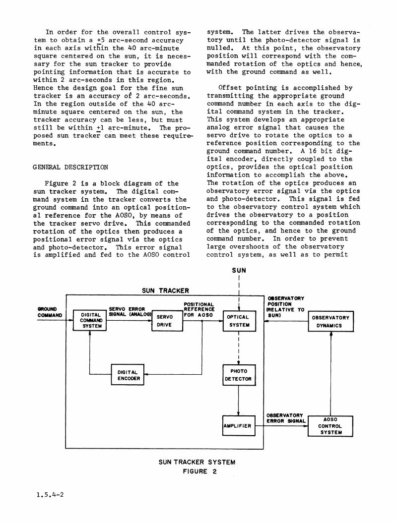
Figure 2 is a block diagram of thesun tracker system. The digital com-mand system in the tracker converts theground command into an optical position-al reference for the AOSO, by means ofthe tracker servo drive. This commandedrotation of the optics then produces apositional error signal via the opticsand photo-detector. This error signalis amplified and fed to the AOSO control
system. The latter drives the observa-tory until the photo-detector signal isnulled. At this point, the observatoryposition will correspond with the com-manded rotation of the optics and hence,with the ground command as well.
Offset pointing is accomplished bytransmitting the appropriate groundcommand number in each axis to the dig-ital command system in the tracker.This system develops an appropriateanalog error signal that causes theservo drive to rotate the optics to areference position corresponding to theground command number. A 16 bit dig-ital encoder, directly coupled to theoptics, provides the optical positioninformation to accomplish the above.The rotation of the optics produces anobservatory error signal via the opticsand photo-detector. This signal is fedto the observatory control system whichdrives the observatory to a positioncorresponding to the commanded rotationof the optics, and hence to the groundcommand number. In order to preventlarge overshoots of the observatorycontrol system, as well as to permit
SUN
SUN TRACKER SYSTEMFIGURE 2
1.5.4-2
the use of a relatively small instantan-eous field of view for the photo-detect-or (+1 deg), the digital command systemin the tracker incorporates rate limit-ing at a value that the observatory finecontrol system is designed to follow(+0.06 deg/sec).
Raster scanning utilizes the samebasic principles as those describedabove. When the observatory has stabi-lized at some offset point, the appro-priate raster scan ground command willcause the following to take place. Inyaw, the tracker digital command systemwill generate a triangular function oftime having a quantization of approxi-mately 1.3 arc-seconds referred to theobservatory position (sun angle). Theconsequent rotation of the yaw opticswill cause the observatory to oscillateback and forth in yaw, corresponding tothe triangular command function. Theslope of this command function is suchthat the observatory yaw rate will be0.06 deg/sec. The peak-to-peak value ofthe command function is such as to pro-duce a 5 arc-minute or 40 arc-minuteobservatory scan, depending on theground command. Meanwhile, the pitchdigital command system is generating aseries of small unidirectional, stepfunctions which occur each time the yawrate reverses. The combination of theseyaw and pitch command functions producesthe desired observatory raster scanning(either 5 arc-minute or 40 arc-minutefield of view). The command systemautomatically stops the scanning afterone raster scan is completed.
OPTICAL SYSTEM
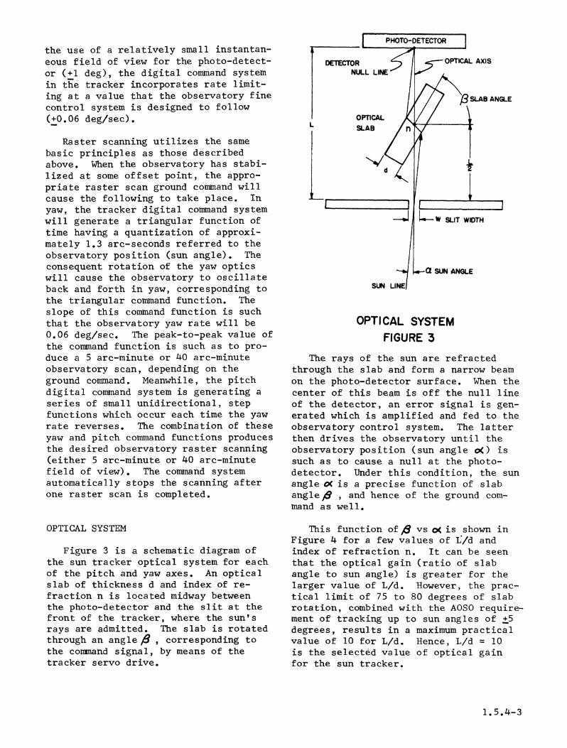
Figure 3 is a schematic diagram ofthe sun tracker optical system for eachof the pitch and yaw axes. An opticalslab of thickness d and index of re-fraction n is located midway betweenthe photo-detector and the slit at thefront of the tracker, where the sun'srays are admitted. The slab is rotatedthrough an angle 6 , corresponding tothe command signal, by means of thetracker servo drive.
eANGLE
OPTICAL SYSTEMFIGURE 3
The rays of the sun are refractedthrough the slab and form a narrow beamon the photo-detector surface. When thecenter of this beam is off the null lineof the detector, an error signal is gen-
erated which is amplified and fed to theobservatory control system. The latterthen drives the observatory until theobservatory position (sun angle o() issuch as to cause a null at the photo-detector. Under this condition, the sun
angle oK is a precise function of slabangle , and hence of the ground com-
mand as well.
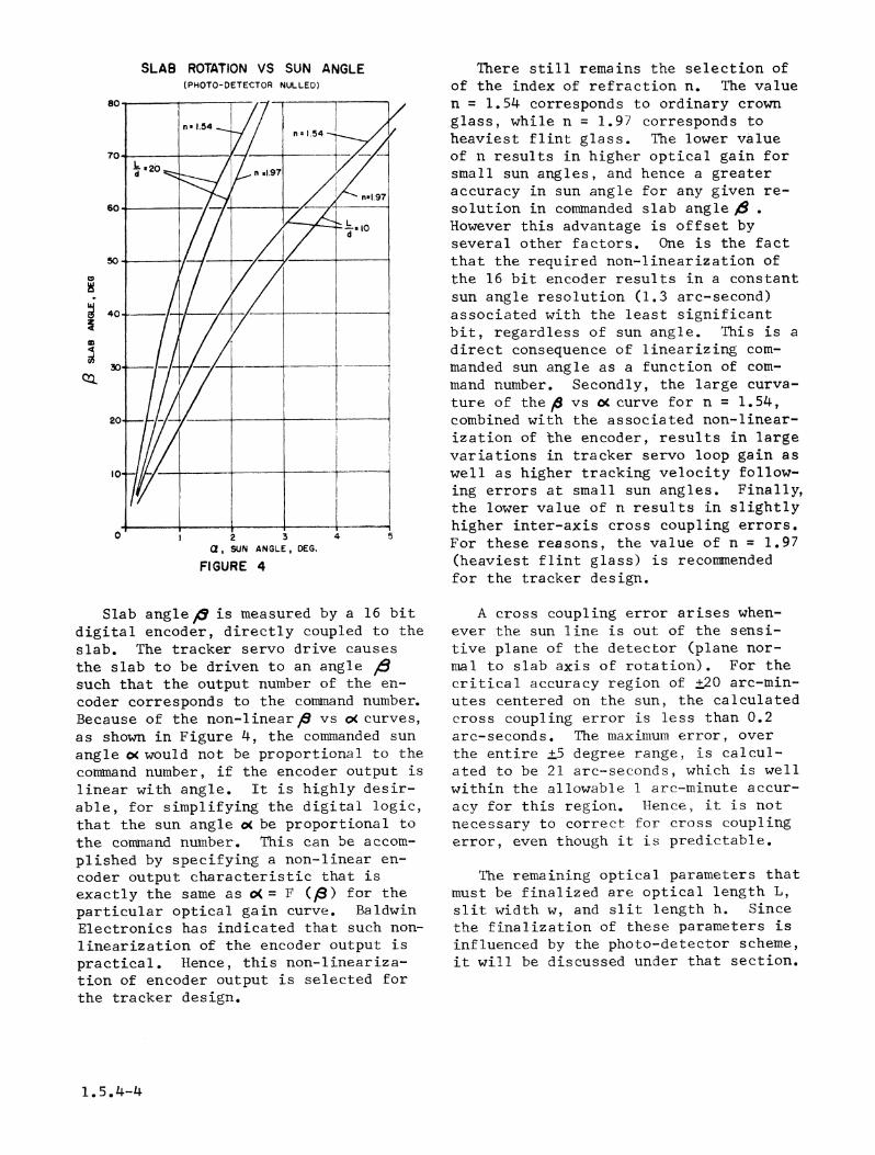
This function of 6 vs oc is shown inFigure 4 for a few values of L/d andindex of refraction n. It can be seen
that the optical gain (ratio of slabangle to sun angle) is greater for thelarger value of L/d. However, the prac-
tical limit of 75 to 80 degrees of slabrotation, combined with the AOSO require-ment of tracking up to sun angles of +5degrees, results in a maximum practicalvalue of 10 for L/d. Hence, L/d = 10is the selected value of optical gainfor the sun tracker.
1.5.14-3
SLAB ROTATION VS SUN ANGLE(PHOTO-DETECTOR NULLED)
4:
a, SUN ANGLE, DEG,
FIGURE 4
Slab anglep is measured by a 16 bitdigital encoder, directly coupled to theslab. The tracker servo drive causesthe slab to be driven to an angle 8such that the output number of the en-coder corresponds to the command number.Because of the non-linear vs oc curves,as shown in Figure 4, the commanded sunangle os would not be proportional to thecommand number, if the encoder output islinear with angle. It is highly desir-able, for simplifying the digital logic,that the sun angle os be proportional tothe command number. This can be accom-plished by specifying a non-linear en-coder output characteristic that isexactly the same as oC = F (BE) for theparticular optical gain curve. BaldwinElectronics has indicated that such non-linearization of the encoder output ispractical. Hence, this non-lineariza-tion of encoder output is selected forthe tracker design.
There still remains the selection ofof the index of refraction n. The valuen = 1.54 corresponds to ordinary crownglass, while n = 1.97heaviest flint glass.of n results in highersmall sun angles, andaccuracy in sun anglesolution in commandedHowever this advantageseveral other factors.
corresponds toThe lower valueoptical gain forhence a greaterfor any given re-slab angle C
> is offset byOne is the fact
that the required non-linearization ofthe 16 bit encoder results in a constantsun angle resolution (1.3 arc-second)associated with the least significantbit, regardless of sun angle. This is adirect consequence of linearizing com-manded sun angle as a function of com-mand number. Secondly, the large curva-ture of the d vs oc curve for n = 1.54,combined with the associated non-linear-ization of the encoder, results in largevariations in tracker servo loop gain aswell as higher tracking velocity follow-ing errors at small sun angles. Finally,the lower value of n results in slightlyhigher inter-axis cross coupling errors.For these reasons, the value of n = 1.97(heaviest flint glass) is recommendedfor the tracker design.
A cross coupling error arises when-ever- the sun line is out of the sensi-tive plane of the detector (plane nor-mal to slab axis of rotation). For thecritical accuracy region of ±20 arc-min-utes centered on the sun, the calculatedcross coupling error is less than 0.2arc-seconds. The maximum error, overthe entire ±5 degree range, is calcul-ated -to be 21 arc-seconds, which is wellwithin the allowable 1 are-minute accur-acy for this region. Hence, it is notnecessary to correct for cross couplingerror, even though it is predictable.
The remaining optical parameters thatmust be finalized are optical length L,slit width w, and slit length h. Sincethe finalization of these parameters isinfluenced by the photo-detector scheme,it will be discussed under that section.
1.5.4-4
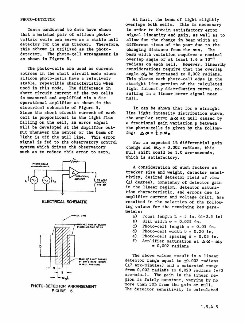
PHOTO-DETECTOR
Tests conducted to date have shownthat a matched pair of silicon photo-voltaic cells can serve as a stable nulldetector for the sun tracker. Therefore,this scheme is utilized as the photo-detector. The photo-c,ell arrangement isas shown in Figure 5.
The photo-cells are used as currentsources in the short circuit mode sincesilicon photo-cells have a relativelystable, repeatible characteristic whenused in this mode. The difference inshort circuit current of the two cellsis measured and amplified via a d-coperational amplifier as shown in theelectrical schematic of Figure 5.Since the short circuit current of eachcell is proportional to the light fluxfalling on the cell, an error signalwill be developed at the Amplifier out-put whenever the center of the beam oflight is off the null line. This errorsignal is fed to the observatory controlsystem which drives thd observatorysuch as to reduce this error to zero.
P.
P1O0O- CELLS
OPERATIONALZI '~"''"~t AMPLIFER (TO AOSO
CONTROL
ELECTRICAL SCHEMATIC
LINE
-MATCHED PAIR OF SILICONPHOTO-VOLTAIC CELLS
PHOTO-DETECTOR ARRANGEMENTFIGURE 5
At nuil, the beam of light slightlyoverlaps both cells.. This is necessaryin order to bbtain satisfactory errorsignal linearity and gain, as well as toallow for the change in beam width atdifferent times of the year due to thechanging distance from the sun. Thebeam width variation requires a nominaloverlap angle of at least 1.6 x 10⁻⁴radians on each cell. However, linearityconsiderations require that the overlapangle &*be increased to 0.002 radians.This places each photo-cell edge in thestraight line portion of the calculatedlight intensity distribution curve, re-sulting in a linear error signal nearnull.
It can be shown that for a straightline light intensity distribution curve,the angular error Ao at null caused bya fractional gain variation p betweenthe photo-cells is given by the follow-ing: Aoll KP=o
For an expected 1% differential gainchange and o(4 0.002 radians, thisnull shift would be 1.0 arc-seconds,which is satisfactory.
A consideration of such factors astracker size and weight, detector sensi-tivity, desired detector field of view(±1 degree), constancy of detector gainin the linear region, detector satura-tion characteristic, and errors due toamplifier current and voltage drift, hasresulted in the selection of the follow-ing values for the remaining key para-meters:
a) Focal length L =.5 in. Cd=.0.5 in)b) Slit width w = 0.025 in.d) Photo-cell length a = 0.05 in.d) Photo-cell width b = 0.20 in.e) Photo-cell spacing s = 0.05 in.f) Amplifier saturation at 4A(= OCo
= 0.002 radians
The above values result in a lineardetector range equal to ±0.002 radians(+7 arc-tninutes) and a saturated rangefroim 0.002 radiafts to 0.020 radians (±+70arc-min.). The gain in the linear re-gion is fairly constant, varying by nomore than 30% from the gain at null.The detector sensltivity is calculated
1. 5.4-5
to be about 0.20#a/arc-sec. This, to-gether with an estimated 0.1. a currentdrift of the operational amplifier, re-sults in an error component of 0.5 arc-seconds. Another angular error com-ponent equal to about 0.5 arc-secondsresults from the expected voltage driftof the amplifier combined with the in-ternal shunt resistance of the photo-cells. Thus the photo-detector designmeets the objectives for field of view,linearity, and accuracy.
DIGITAL COMMAND SYSTEM
The digital system generates a seriesof command numbers in each axis inaccordance with the transmitted groundcommand. The output of the 16 bit dig-ital encoder is compared with the exist-ing value of the generated command num-ber. The difference is converted to ananalog error signal which is fed to theservo system controlling the rotationof the optical slab. Thus, the slab isdriven to an angle,4 such that the en-coder output matches the generated com-mand number. As explained previously,the photo-detector error signal willdrive the AOSO to a sun angle o( that isa precise function of the commanded slabangle O . Hence the final sun angle >is directly related to the generatedcommand number. This relation (cK vscommand number) is perfectly linearsince the encoder output characteristicis tailored to the 6 vs oC curve of theoptical slab. The overall gain is suchthat one count of the 16 bit digitalsystem corresponds to 1.32 arc-secondsof sun angle.
In offset pointing, the ground com-mand (offset Pointing) number in eachaxis is stored in the command generator.The latter then causes a command re-gister to be counted up or down fromits last value until it equals the off-set pointing number. The counting rateis limited to 164 counts/sec, or 0.060/sec of sun angle. The encoder outputis compared with the present number inthe command register by means of aserial subtractor. The difference isconverted to an analog signal, by means-
of a D/A converter. This error signalcauses the optical slab to be driven toa position corresponding to the presentnumber in the command register. Hencethe AOSO will be driven to the sun anglecorresponding to this number. Since thecommand register number is changing atthe rate of 164 counts/sec the AOSO willbe driven at 0.060/sec. The spacecraftwill stabilize about the desired offsetpoint when the command register numberreaches and stops at the ground commandnumber.
Raster scanning about any offset pointcan begin once the AOSO has stabilizedabout the offset point. The appropriateground command will then cause the fol-lowing to take place. The number in theyaw command register will be increasedat the rate of 164 counts/sec, or 0.060/sec. When the command register numberhas been increased by the equivalent of5 arc-minutes or 40 arc-minutes, depend-ing on the desired raster scan, the com-mand generator will cause a smooth re-versal in the command register countingrate. After about 3.6 seconds, this re-versal will be completed and the commandregister number will be counting down atthe rate of 164 counts/sec. When thecommand register number reaches its ori-ginal value, another smooth reversaloccurs, and the process is repeated.Concurrently, the pitch command registeris counted down by 15 counts (20 arc-seconds) durifng every yaw reversal. Thenet result is that the spacecraft is com-manded to perform raster scanning of thedesired width at the rate of 0.06 deg/sec. The pitch and yaw command registerautomatically stop counting after onecomplete raster scan. This occurs after15 lines for the 5 arc-minute commandand after 120 lines for the 40 arc-min-ute command.
SERVO DRIVE SYSTEM
The servo drive system positions theoptical slab in accoradnce with the com-mand number generated by the digitalcommand system. This is accomplished bycomparing the slab angle position (en-coder number) with the command number,
1.5.4-6
converting the difference to an analogsignal via the D/A converter, and feed-ing this s'ignal to the servo drivesystem. The latter then drives the slabso as to reduce this difference to zero.
The basic design criteria for theservo system are a bandwidth of approx-imately 40 rad/sec, in order that it befast compared to the AOSO control system,and a total random servo following errorof less than 1 arc-second referred tothe spacecraft. On this basis, two dif-ferent servo systems have been designed.One is a geared drive which utilizes aninertially damped servomotor to drivethe optical slab, via anti-backlashgearing. This design was selectedinitially because of its simplicity andthe relative ease in predicting its ser-vo performance. A breadboard model ofthis drive has been constructed and suc-cessfully operated. The second designis a direct drive which utilizes a d-ctorquer motor and d-c tachometer, bothof which are directly coupled to theoptical slab. This design has beeninvestigated via analog simulation. Thelatter design, though it contains morecomponents, appears preferable becauseof its greater mechanical reliabilitycompared to the geared servo drive.For this reason, the direct servo driveis recommended for the sun tracker.
AMAPUFIER/A SLAS-LEAD 0-C MOTOR COMMANDEODGTL CONVERTER NETWORK a LOAD SUN ANLE OL
ENCOCER
DRECT SERVO DRISVEBLOCK DIAGRAM
FIGURE 6
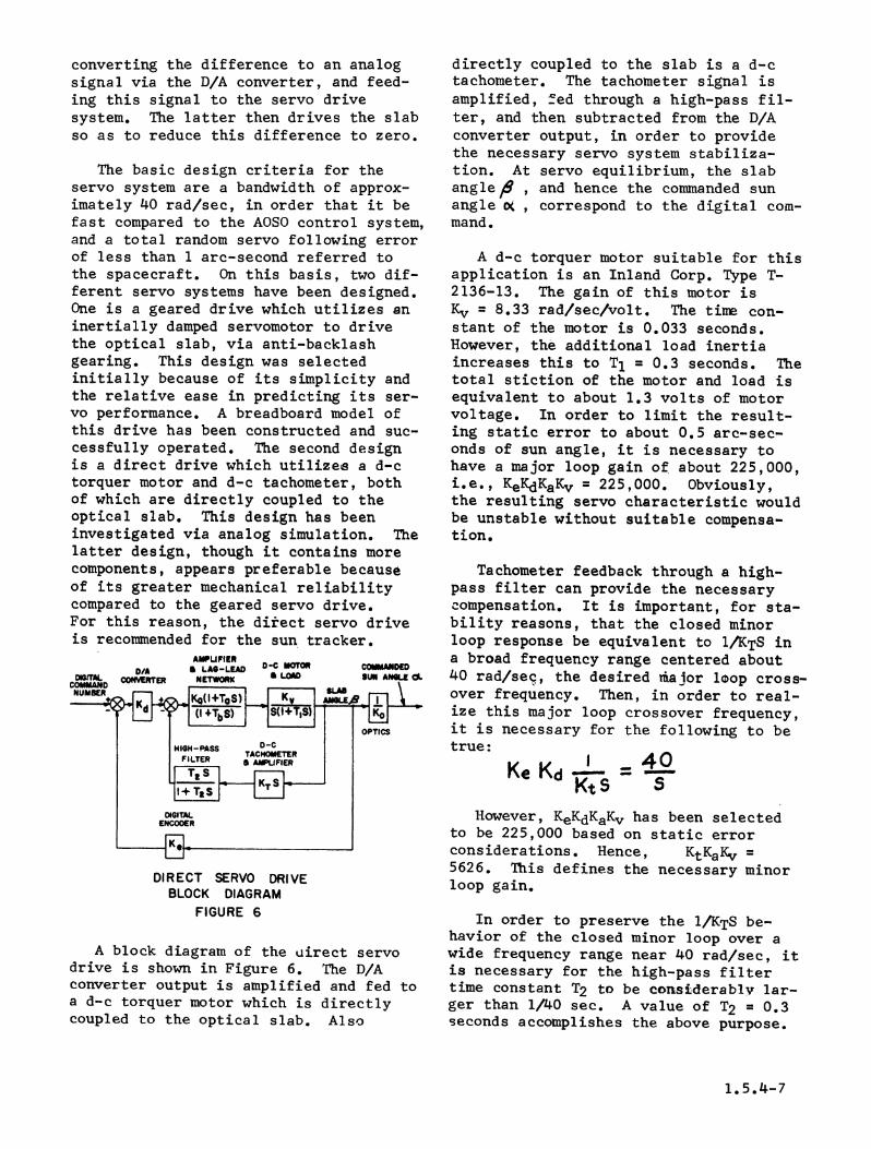
A block diagram of the uirect servodrive is shown in Figure 6. The D/Aconverter output is amplified and fed toa d-c torquer motor which is directlycoupled to the optical1 slab. Also
directly coupled to the slab is a d-ctachometer. The tachometer signal isamplified, fed through a high-pass fil-ter, and then subtracted from the D/Aconverter output, in order to providethe necessary servo system stabiliza-tion. At servo equilibrium, the slabangler , and hence the commanded sunangle o , correspond to the digital com-mand.
A d-c torquer motor suitable for thisapplication is an Inland Corp. Type T-2136-13. The gain of this motor isKv = 8.33 rad/sec/volt. The time con-stant of the motor is 0.033 seconds.However, the additional load inertiaincreases this to T1 = 0.3 seconds. Thetotal stiction of the motor and load isequivalent to about 1.3 volts of motorvoltage. In order to limit the result-ing static error to about 0.5 arc-sec-onds of sun angle, it is necessary tohave a major loop gain of about 225,000,i.e., KeKdKaKv = 225,000. Obviously,the resulting servo characteristic wouldbe unstable without suitable compensa-tion.
Tachometer feedback through a high-pass filter can provide the necessaryCompensation. It is important, for sta-bility reasons, that the closed minorloop response be equivalent to 1/KTS ina broad frequency range centered about40 rad/seq, the desired iaajor loop cross-over frequency. Then, in order to real-ize this major loop crossover frequency,it is necessary for the following to betrue:
1 4
KtS SHowever, KeKdKaKv has been selected
to be 225,000 based on static errorconsiderations. Hence, KtKaKv =5626. This defines the necessary minorloop gain.
In order to preserve the 1/KTS be-havior of the closed minor loop over awide frequency range near 40 rad/sec, itis necessary for the high-pass f'iltertime constant T2 to be considerablv lar-ger than 1/40 sec. A value of T2 = 0.3seconds accomplishes the above purpose.
1.5.4-7
The lag-lead network in the minorloop forward path is introduced in orderto 1 imit the minor loop bandwidth, with-out affecting the compensated major loopcharacteristic in the frequency range ofinterest. Otherwise, an excessive minorloop bandwidth, together with the usualhigher order time constants, would makethe system unfeasible. The selectedvalues for the lag-lead network are Ta =0.0025 sec and Tb = 0.125 sec.
An analog simulation of the systemhas been performed, including stiction.The results indicate good servo perfor-mance, in both the offset pointing andraster scanning modes of the sun tracker.The occasional limit cycle that occurshas an amplitude, referred to the space-craft, only slightly higher than the 0.5arc-seconds necessary to overcome stic-tion.
ERROR ANALYSIS
The following is a listing of space-craft attitude errors caused by the suntracker inaccuracies discussed previous-ly. The magnitudes of these error com-ponents are those associated with smallsun angles (up to +20 arc-minutes).While a few of the error components in-crease in magnitude for the larger sunangles, this is not critical because ofthe much larger value of allowabletracker error (1 arc-minute) outside ofthe fine accuracy region.
Error Source Magnitude of Error(arc-seconds)
Digital system resolution 1.32(1 count)
Photo-detector null shift 1.0Detector amplifier current 0.5
driftDetector amplifier voltage 0.5
driftInter-axis cross coupling 0.2Index of refraction varia- 0.4
t ionRandom servo error 1.0
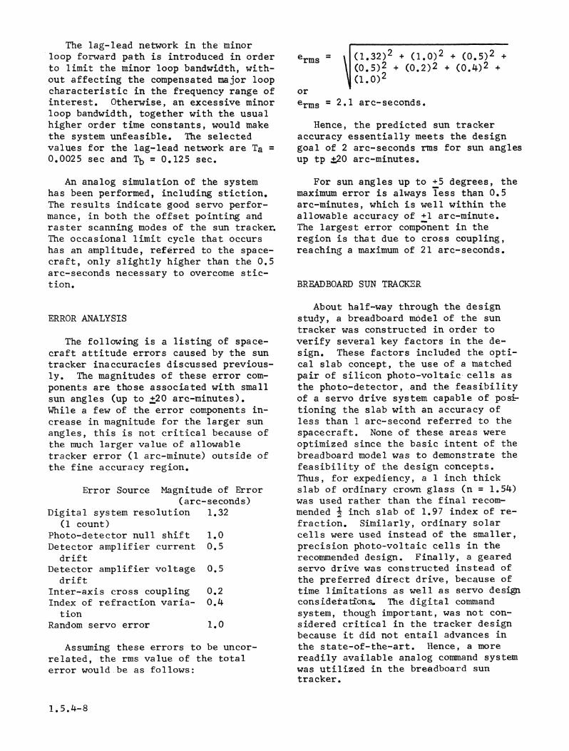
Assuming these errors to be uncor-related, the rms value of the totalerror would be as follows:
erms = (1.32)2 + (1.0)2 + (0.5)2 +
\ (0.5)2 + (1.2)2 + (0.4)2 +
\(1.)2orerms = 2.1 arc-seconds'.
Hence, the predicted sun trackeraccuracy essentially meets the designgoal of 2 arc-seconds rms for sun anglesup tp ±20 arc-minutes.
For sun angles up to +5 degrees, themaximum error is always less than 0.5arc-minutes, which is well within theallowable accuracy of +1 arc-minute.The largest error component in theregion is that due to cross coupling,reaching a maximum of 21 arc-seconds.
BREADBOARD SUN TRACKER
About half-way through the designstudy, a breadboard model of the suntracker was constructed in order toverify several key factors in the de-sign. These factors included the opti-cal slab concept, the use of a matchedpair of silicon photo-voltaic cells asthe photo-detector, and the feasibilityof a servo drive system capable of posi-tioning the slab with an accuracy ofless than 1 are-second referred to thespacecraft. None of these areas wereoptimized since the basic intent of thebreadboard model was to demonstrate thefeasibility of the design concepts.Thus, for expediency, a 1 inch thickslab of ordinary crown glass (n = 1.54)was used rather than the final recom-mended 2 inch slab of 1.97 index of re-fraction. Similarly, ordinary solarcells were used instead of the smaller,precision photo-voltaic cells in therecommended design. Finally, a gearedservo drive was constructed instead ofthe preferred direct drive, because oftime limitations as well as servo designconsidetati:ons. The digital commandsystem, though important, was not con-sidered critical in the tracker designbecause it did not entail advances inthe state-of-the-art. Hence, a morereadily available analog command systemwas utilized in the breadboard suntracker.
1.5.4-8
The breadboard tracker servo drivereceives its command signal from a 25speed 400 cycle control transmitter (25pair of poles) having an absolute accur-acy of 20 arc-seconds (about 1 arc-sec-ond referred to the spacecraft). Thecontrol transformer, directly coupled tothe optical slab, develops an error sig-nal proportional to the difference be-tween slab angle,6 and the command angTe.At servo equilibrium, a photo-detectorerror signal is generated by a pair ofsolar cells, as indicated by a sensitivevoltmeter. The operator, simulating theAOSO control system, turns the LeitzHead, on which the sun tracker is mount-ed, until the photo-detector signal iszero. The angle through which the suntracker is turned is the spacecraft' sunangle oC , which in turn corresponds tothe command angle ,8 .
The breadboard tracker focal lengthis 10 inches. Thus, with the one inchthick slab of crown glass (n = 1.54),the recommended value of L/d = 10 ismaintained. In order to obtain a lightbeam at the detector of comparable widthand intensity to that attainable in sun-light, a comparitively large slit isused in conjunction with a collitnatedlight source,
The tracker optical characteristicswere checked by determining the sunangle i , as measured by the LeitzHead, for various values of commandanglef up to 75 degrees. The latterwas measured via a circular scale on thecontrol transmitter. The resultant cureof,# vs a corresponds, within measure-ment accuracies, to the theoreticallyderived curve in Figure 4. This de-monstrated the validity of the opticalslab concept and the associated theoret-ical calculations-.
In order to determine the resolutionand accuracy of the servo drive, in thecritical accuracy region (10(1 4 20arc-minutes), a precision method formeasuring command angle,8 was followed.This consisted of directing a sharplydefined beam from a collimated lightsource to a mirror attached to the con-trol transmitter shaft, and thence onto
a wall about 20 feet from the mirror.The measurement accuracy obtained inthis manner was equivalent to a fractionof 1 arc-second referred to the LeitzHead (spacecraft). A given commandangle,8 could thus be repeated manytimes with considerable accuracy. Thetotal spread in the readings of thecorresponding sun angle o( , over a shorttime period, was always less than +1arc-second. This proved that the servosystem introduced a static error lessthan 1 arc-second referred to the space-craft.
The accuracy of the photo-detectorwas checked by repeating the above mea-surements over a longer time interval(8 Hours) as well as by separate mea-surements of the photo-detector alone.Both sets of measurements indicated an8 hour drift of approximately 5 arc-seconds, nearly all of which could beattributed to temperature changes at thesolar cells.
The above results were very encour-aging for the following reasons: Thesolar cells, though "matched", were farfrom the precision match that can beobtained with photo-voltaic cells.Secondly, for expediency, the solarcells were operated essentially in theopen circuit mode rather than the re-commended short circuit mode. This re-sulted in a greater change in cell out-put with temperature. Thirdly, noattempt was made to minimize temperaturevariations between the cells through theuse of an appropriate heat sink. Final-ly, in order to obtain a high detectorsensitivity at null, the light beamoverlap on each cell at null was muchlarger than the 0.002 radians in therecommended design. This magnified thedrift caused by solar cell temperaturevariations. It is believed that anoptimization of these factors, as pre-viously discussed, will result in anorder of magnitude improvement in accur-acy. Hence, a 1 arc-second detectoraccuracy, over a +200C ambient tempera-ture variation, is not unreasonable toexpect from an optimized design.
1.5.4-9
In summary, the test results of thebreadboard tracker system verified theoptical slab concept and calculations;demonstrated the feasibility of design-ing a servo drive system that contri-butes less than 1 arc-second of error tothe spacecraft attitude orientation; andconfirmed the inherent aacuracy of thephoto-detector scheme.
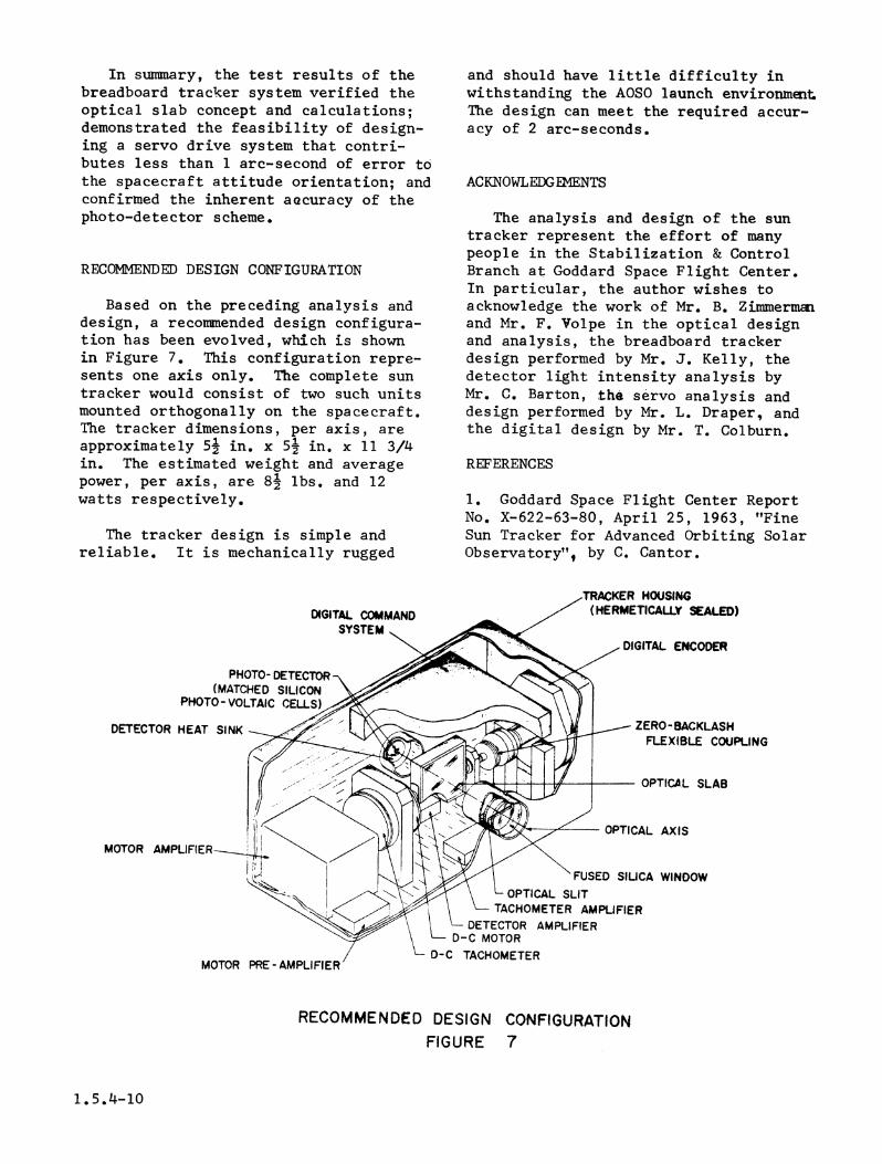
RECOMMENDED DESIGN CONFIGURATION
Based on the preceding analysis anddesign, a recommended design configura-tion has been evolved, which is shownin Figure 7. This configuration repre-sents one axis only. The complete suntracker would consist of two such unitsmounted orthogonally on the spacecraft.The tracker dimensions, per axis, areapproximately 51 in. x 51 in. x 11 3/4in. The estimated weight and averagepower, per axis, are 81 lbs. and 12watts respectively.
The tracker design is simple andreliable. It is mechanically rugged
DIGITAL COMMANDSYSTEM
PHOTO- DETECTOR(MATCHED SILICON
PHOTO- VOLTAIC CELLS)
DETECTOR HEAT SINK
and should have little difficulty inwithstanding the AOSO launch environmet.The design can meet the required accur-acy of 2 arc-seconds.
ACKNOWLEDGEMENTS
The analysis and design of the suntracker represent the effort of manypeople in the Stabilization & ControlBranch at Goddard Space Flight Center.In particular, the author wishes toacknowledge the work of Mr. B. Zimmermaiand Mr. F. Volpe in the optical designand analysis, the breadboard trackerdesign performed by Mr. J. Kelly, thedetector light intensity analysis byMr. C. Barton, the servo analysis anddesign performed by Mr. L. Draper, andthe digital design by Mr. T. Colburn.
REFERENCES
1. Goddard Space Flight Center ReportNo. X-622-63-80, April 25, 1963, "FineSun Tracker for Advanced Orbiting SolarObservatory", by C. Cantor.
DIGITAL ENCODER
- ZERO- BACKLASHFLEXIBLE COUPUNG
OPTICAL SLAB
OPTICAL AXISMOTOR
L OPTICL N FUSED SIUCA WINDOWLOPTICAL SLIT
TACHOMETER AMPLIFIERDETECTOR AMPLIFIER
D-C MOTORD-C TACHOMETER
MOTOR
RECOMMENDED DESIGN CONFIGURATIONFIGURE 7
1.5.4-10