final technologies assessment for existing once-through ...€¦ · final technologies assessment...
TRANSCRIPT

Final Technologies Assessment
for Existing Once-Through Cooling System Report No. 25762-000-30R-G01G-00010
Bechtel Confidential i

Final Technologies Assessment
for Existing Once-Through Cooling System Report No. 25762-000-30H-G01G-00001
Bechtel Power Corporation. Report issued September 17, 2014 i
Independent Third-Party Final Technologies Assessment for the Alternative Cooling Technologies or Modifications to the Existing Once-Through Cooling System for Diablo Canyon Power Plant Report No. 25762-000-30H-G01G-00001 Prepared by Bechtel Power Corporation
Revision Date Affected Sections
0 8/22/14 Issued Report
1 9/17/14 Incorporated Editorial Comments
CIVIL
GOVERNMENT SERVICES
MINING & METALS
OIL, GAS & CHEMICALS
POWER

Final Technologies Assessment
for Existing Once-Through Cooling System Report No. 25762-000-30H-G01G-00001
Bechtel Power Corporation. Report issued September 17, 2014 ii
PACIFIC GAS AND ELECTRIC COMPANY (PG&E) DIABLO CANYON POWER PLANT
ONCE-THROUGH COOLING SYSTEM ALTERNATIVE OPTIONS REPORT
IMPORTANT NOTICE
Although care has been taken in preparing the information contained in this report, Bechtel Power Corporation (Bechtel) does not and cannot guarantee the accuracy, completeness, or feasibility of any information contained herein, and Bechtel provides no warranty and accepts no responsibility for the accuracy, completeness, or feasibility of any such information. In preparing the report, Bechtel may have had to rely upon assumptions (especially as to future conditions and events) that may or may not be expressed herein. Accordingly, neither Bechtel nor any person acting on its behalf assumes any liability to any party with respect to the use of, or for damages resulting from the use of, any information contained in this report for any purpose whatsoever and whether or not contemplated herein. No reliance by any party should be made based upon the accuracy, completeness, or feasibility of the information contained in this report, and any party using the information contained herein does so at its sole risk.
For the avoidance of doubt, any cost estimate or unit rates included or referred to in this report do not constitute an offer of any nature for any purpose on the part of Bechtel.
This report was prepared by Bechtel under Contract No. 4600018224 expressly for the use and benefit of Pacific Gas and Electric Company. Any party that reviews this report, by that act, acknowledges that it understands and accepts the statements, disclaimers, and limitations set out in this Important Notice.

Final Technologies Assessment
for Existing Once-Through Cooling System Report No. 25762-000-30H-G01G-00001
Bechtel Power Corporation. Report issued September 17, 2014 iii
Table of Contents
Section Page
1 Executive Summary ............................................................................................................. 1
1.1 Criterion 10, Licensing Nuclear-Specific Assessment .................................................. 4
1.2 Criterion 11 .................................................................................................................. 4
1.2.1 Permitting ......................................................................................................................... 5
1.2.2 Preliminary Design ........................................................................................................... 5
1.2.3 Schedule and Cost Estimate ........................................................................................... 8
1.3 Phase 2 Results .......................................................................................................... 8
2 Introduction .........................................................................................................................17
3 Licensing Nuclear-Specific Assessment (Criterion 10) ........................................................17
3.1 Alternatives for Closed-Cycle Cooling Technology .....................................................18
3.2 Alternatives to Existing Intake Technology ..................................................................19
3.2.1 10 CFR 50.59................................................................................................................. 19
3.2.2 FSARU ........................................................................................................................... 20
3.3 Assessment of Closed-Cycle Cooling Technology ......................................................20
3.3.1 Seismic .......................................................................................................................... 21
3.3.2 Operability ...................................................................................................................... 21
3.3.3 Transient Analyses ........................................................................................................ 21
3.3.4 Nuclear Fuel (Accident Analyses).................................................................................. 22
3.3.5 Hydraulic Design ............................................................................................................ 22
3.3.6 Probabilistic Risk Assessment ....................................................................................... 22
3.3.7 Instrumentation, Controls, and Alarms .......................................................................... 22
3.4 Assessment of Intake Technology Alternatives ...........................................................22
3.4.1 Alternative 1–Onshore Mechanical (Active) Intake Fine Mesh Screening System ....... 23
3.4.2 Alternative 2–Offshore Modular Wedge Wire or Similar Exclusion Screening
Systems ......................................................................................................................... 24
3.5 Conclusion—Criterion 10 Assessment ........................................................................26
3.6 Facility Operating License/Technical Specifications ....................................................27
3.7 Environmental Protection Plan (Non-Radiological) .....................................................27
4 Preliminary Design Development ........................................................................................27
4.1 Onshore Mechanical (Active) Intake Fine Mesh Screening Technology ......................27
4.1.1 Hydraulic Evaluation of the Dual-Flow Screen Retrofit ................................................. 28
4.1.2 Justification of Selecting 1 mm Fine Mesh Opening...................................................... 29
4.1.3 Mechanical Design ........................................................................................................ 30
4.1.4 Control System Design .................................................................................................. 32
4.1.5 Civil Design .................................................................................................................... 32
Final Technologies Assessment
for Existing Once-Through Cooling System Report No. 25762-000-30H-G01G-00001
Bechtel Power Corporation. Report issued September 17, 2014 iv
4.1.6 Electrical Design ............................................................................................................ 34
4.1.7 Permitting ....................................................................................................................... 34
4.2 Offshore Modular Wedge Wire Screening Technology ...............................................42
4.2.1 Existing Conditions and Basic Data ............................................................................... 43
4.2.2 Alternative Concept A: Offshore Tunnel ........................................................................ 47
4.2.3 Alternative Concept B: Multiple Offshore Buried Pipes ................................................. 57
4.2.4 Modular Wedge Wire Screening Technology and Design Requirements ..................... 67
4.2.5 Comparison of Offshore Modular Wedge Wire System Alternatives ............................. 71
4.2.6 Final Offshore Modular Wedge Wire Screening Technology Selection ........................ 71
4.2.7 Future Actions ................................................................................................................ 72
4.2.8 Permitting ....................................................................................................................... 72
4.2.9 Sources .......................................................................................................................... 80
4.3 Closed-Cycle Cooling Technology ..............................................................................80
4.3.1 Dry/Air Cooling Systems—Overview ............................................................................. 84
4.3.2 Passive Draft Dry/Air Cooling ........................................................................................ 97
4.3.3 Mechanical (Forced) Draft Dry/Air Cooling .................................................................. 101
4.3.4 Wet Cooling Technologies—Overview ........................................................................ 106
4.3.5 Wet Natural Draft Cooling ............................................................................................ 111
4.3.6 Wet Mechanical (Forced) Draft Cooling ...................................................................... 117
4.3.7 Hybrid Wet/Dry Cooling ............................................................................................... 123
4.3.8 Permitting ..................................................................................................................... 129
5 Construction Approach ...................................................................................................... 145
5.1 Onshore Mechanical (Active) Intake Fine Mesh Screening Technology .................... 145
5.1.1 Fish Recovery System ................................................................................................. 146
5.1.2 Dual-Flow Traveling Screens ....................................................................................... 146
5.2 Offshore Modular Wedge Wire Screening Technology ............................................. 147
5.2.1 Installation of Main Intake Tunnel Drop Shaft .............................................................. 148
5.2.2 Installation of Main Intake Tunnel Starter Tunnel ........................................................ 149
5.2.3 Installation of Main Intake Tunnel Starter Tunnel Liner ............................................... 151
5.2.4 Installation of the Main Intake Tunnel .......................................................................... 152
5.2.5 Installation of Rock Bolts and Ceiling Reinforcement Supports .................................. 155
5.2.6 Installation of Auxiliary Air and Pumping Systems ...................................................... 155
5.2.7 Disassembly and Removal of Conveyor, TBM Disposition, and Rail System
Removal ....................................................................................................................... 155
5.2.8 Installation of Offshore Intake Drop Shafts .................................................................. 156
5.2.9 Main Drop Shaft Modification ....................................................................................... 160
5.2.10 Installation of Cofferdam for Emergency Backup Water Supply ................................. 160
5.2.11 Installation of Reinforced Concrete Emergency Water Structure ................................ 160

Final Technologies Assessment
for Existing Once-Through Cooling System Report No. 25762-000-30H-G01G-00001
Bechtel Power Corporation. Report issued September 17, 2014 v
5.2.12 Installation of the Enclosed Shoreline Breakwater ...................................................... 160
5.2.13 Installation of the Interior Breakwater Seal Liner ......................................................... 160
5.3 Closed-Cycle Cooling, Passive Draft Dry Air; Mechanical Draft Dry Air; Wet Natural Draft; Wet Mechanical Draft; and Hybrid Wet/Dry Cooling ............................ 161
5.3.1 230 kV Power Transmission Line Rerouting ............................................................... 162
5.3.2 500 kV Switchyard Expansion ..................................................................................... 162
5.3.3 Excavation Activities .................................................................................................... 162
5.3.4 Circulating Water Piping and Duct Excavation ............................................................ 164
5.3.5 Cooling Tower Erection ............................................................................................... 165
5.3.6 Pumphouses ................................................................................................................ 167
5.3.7 Concrete Production .................................................................................................... 167
5.3.8 Structural Backfill ......................................................................................................... 167
5.3.9 Parking ......................................................................................................................... 167
5.3.10 Construction Workforce Populations ........................................................................... 167
6 Schedule Development ..................................................................................................... 168
6.1 Summary .................................................................................................................. 168
6.2 Base Key Schedule Durations .................................................................................. 168
6.3 General Schedule Qualifications and Assumptions ................................................... 169
6.4 Closed-Cycle Cooling Technologies ......................................................................... 169
6.5 Closed-Cycle Schedule Qualifications and Assumptions .......................................... 170
6.6 Key Events that Start Prior to NTP............................................................................ 176
6.7 Critical Path Activities ............................................................................................... 176
6.8 Outage Work ............................................................................................................ 177
6.9 Schedule Risks ......................................................................................................... 177
6.10 Onshore Mechanical Fine Mesh Screening Technology ........................................... 178
6.11 Key Events that Start Prior to NTP............................................................................ 178
6.12 Critical Path Activities ............................................................................................... 179
6.13 Offshore Modular Wedge Wire Screening System Technology ................................. 179
6.14 Schedule Qualifications and Assumptions ................................................................ 181
6.15 Key Events that Start Prior to NTP............................................................................ 181
6.16 Critical Path Activities ............................................................................................... 181
6.17 Schedule Confidence ............................................................................................... 183
7 Estimate Development ...................................................................................................... 183
7.1 Estimate Overview .................................................................................................... 183
7.2 Estimate Classification .............................................................................................. 184
7.3 Estimate Summary for All Technologies ................................................................... 186
7.3.1 Estimate Summary Explained ...................................................................................... 186
7.3.2 Estimate Summary for Mechanical (Forced) Dry/Air Cooling ...................................... 188
Final Technologies Assessment
for Existing Once-Through Cooling System Report No. 25762-000-30H-G01G-00001
Bechtel Power Corporation. Report issued September 17, 2014 vi
7.3.3 Estimate Summary for Passive Draft Dry/Air Cooling ................................................. 189
7.3.4 Estimate Summary for Wet Mechanical (Forced) Draft Cooling .................................. 190
7.3.5 Estimate Summary for Wet Natural Draft Cooling ....................................................... 191
7.3.6 Estimate Summary for Hybrid Wet/Dry Cooling .......................................................... 192
7.3.7 Estimate Summary for Onshore Mechanical (Active) Fine Mesh Screening .............. 193
7.3.8 Estimate Summary for Offshore Modular Wedge Wire Screening .............................. 194
7.4 Quantity Development .............................................................................................. 195
7.4.1 Mechanical (Forced) Dry/Air Cooling ........................................................................... 196
7.4.2 Passive Draft Dry/Air Cooling ...................................................................................... 197
7.4.3 Wet Mechanical (Forced) Draft Cooling ...................................................................... 198
7.4.4 Wet Natural Draft Cooling ............................................................................................ 199
7.4.5 Hybrid Wet/Dry Cooling ............................................................................................... 200
7.4.6 Onshore Mechanical Fine Mesh Screening ................................................................. 201
7.4.7 Offshore Modular Wedge Wire Screening System ...................................................... 202
7.5 Direct Material and Subcontract Pricing .................................................................... 203
7.5.1 Closed-cycle Cooling Technology Supply Bids ........................................................... 203
7.5.2 Onshore Mechanical Fine Mesh Screening Technology Supply Bids ......................... 203
7.5.3 Closed-Cycle Cooling Technolgy Supply and Install Bids ........................................... 203
7.5.4 Offshore Modular Wedge Wire Screening System Technology Supply and
Install Bids .................................................................................................................... 203
7.6 Construction ............................................................................................................. 204
7.6.1 Direct Craft Labor Hours .............................................................................................. 204
7.6.2 Craft Labor Wages ....................................................................................................... 204
7.6.3 Field Indirect Costs ...................................................................................................... 204
7.7 Home Office Services ............................................................................................... 205
7.8 Engineering Services Subcontracts .......................................................................... 205
7.8.1 Closed-Cycle Cooling Technologies ............................................................................ 205
7.8.2 Onshore Mechanical Fine Mesh Screening Technology ............................................. 205
7.8.3 Offshore Modular Wedge Wire Screening System Technology .................................. 205
7.9 Procurement Services Subcontracts ......................................................................... 205
7.9.1 Field Non-manual ........................................................................................................ 205
7.9.2 Startup ......................................................................................................................... 206
7.10 Other Costs .............................................................................................................. 206
7.10.1 Insurances ................................................................................................................... 206
7.10.2 Securities ..................................................................................................................... 206
7.10.3 Warranty ...................................................................................................................... 206
7.10.4 Taxes ........................................................................................................................... 206
7.10.5 Escalation .................................................................................................................... 206

Final Technologies Assessment
for Existing Once-Through Cooling System Report No. 25762-000-30H-G01G-00001
Bechtel Power Corporation. Report issued September 17, 2014 vii
7.10.6 Contingency ................................................................................................................. 206
7.10.7 Permits ......................................................................................................................... 206
7.10.8 PG&E Costs ................................................................................................................. 207
7.11 Qualifications and Assumptions ................................................................................ 207
7.12 Exclusions ................................................................................................................ 208
8 References ........................................................................................................................ 210
Final Technologies Assessment
for Existing Once-Through Cooling System Report No. 25762-000-30H-G01G-00001
Bechtel Power Corporation. Report issued September 17, 2014 viii
List of Figures Page
Figure 1-1. Phase 1 Review Process for Each Technology ............................................................................. 10
Figure 1-2. Phase 2 Review Process for Each Technology ............................................................................. 11
Figure 1-3. Phase 2 Estimating Process for Each Technology ........................................................................ 12
Figure 1-4. Plant Site Rendering Showing the Wet Natural Draft Configuration ............................................. 13
Figure 4.2-1. DCPP Site Location Map (Contour elevations = feet below MLLW) .......................................... 44
Figure 4.2-2. DCPP Bathymetry Map (Contour elevations = feet below MLLW)............................................. 45
Figure 4.2-3. DCPP Bathymetry/Tunnel for 6-mm-Slot Screen Layout (Contour elevations = feet below MLLW) .............................................................................................. 49
Figure 4.2-4. DCPP General Layout of Breakwaters ........................................................................................ 50
Figure 4.2-5. DCPP Offshore Modular Wedge Wire Tunnel System (Sectional View) ................................... 51
Figure 4.2-6. DCPP 6-mm-Slot Modular Wedge Wire Screen Intake System (Plan View) ............................. 52
Figure 4.2-7. DCPP 6-mm-Slot Modular Wedge Wire Screen Intake System (Sectional Views) ................... 53
Figure 4.2-8. DCPP 2-mm-Slot Modular Wedge Wire Screen Intake System (Plan View) ............................. 54
Figure 4.2-9. DCPP 2-mm-Slot Modular Wedge Wire Screen Intake System (Sectional Views) ................... 55
Figure 4.2-10. DCPP Emergency Cooling Water Intake Structure Details ...................................................... 56
Figure 4.2-11. DCPP Bathymetry/Buried Pipe Layout with 6-mm-Slot Screens (Contour elevations = feet below MLLW) .............................................................................................. 58
Figure 4.2-12. DCPP Layout of Offshore Modular Wedge Wire Screen Technology (Buried Pipe Alternative) ........................................................................................................................ 59
Figure 4.2-13. DCPP Offshore Modular Wedge Wire Buried Pipe System (Sectional View) ......................... 60
Figure 4.2-14. DCPP 6-mm-Slot Modular Wedge Wire Screen Intake System (Plan View) .......................... 61
Figure 4.2-15. DCPP 6-mm-Slot Modular Wedge Wire Screen Intake Assembly (Sectional Views) ............. 62
Figure 4.2-16. DCPP 2-mm-Slot Modular Wedge Wire Screen Intake System (Plan View) .......................... 63
Figure 4.2-17. DCPP 2-mm-Slot Modular Wedge Wire Screen Intake Assembly (Sectional Views) ............. 64
Figure 4.2-18. DCPP Potential Buried Pipe Trench Scenarios (Based on Seabed Geology) ........................ 65
Figure 4.2-19. DCPP Intake Screen Assembly ................................................................................................. 68
Figure 4.2-20. DCPP Preliminary Intake Screen Specifications (6-mm Slots) ................................................ 69
Figure 4.2-21. DCPP Preliminary Intake Screen Specifications (2-mm Slots) ................................................ 70
Figure 4.3-1. Average Circulating Water Temperature per Month ................................................................... 82
Figure 4.3-2. Average Condenser Backpressure per Month ............................................................................ 82
Figure 4.3-3. Average Lost Output per Month................................................................................................... 83
Figure 4.3-4. Plant Site Rendering Showing Wet Natural Draft Technology ................................................... 85
Figure 4.3-5. Circulating Water System ............................................................................................................ 89
Figure 4.3-6. Site Development Plan (Plant Site Area) .................................................................................... 93
Figure 4.3-7. Existing 230 kV and 500 kV Power Line Rerouting .................................................................... 95
Figure 4.3-8. 500 kV Power Supply to the Cooling Towers .............................................................................. 96
Figure 4.3-9. Passive Draft Dry/Air-Cooling Site Configuration ........................................................................ 97
Figure 4.3-10. Passive Draft Dry/Air Cooling—Main Switchgear Electrical Building ....................................... 99
Figure 4.3-11. Passive Draft Dry/Air Cooling—Cooling Tower and Pumphouse Electrical Buildings .......... 100
Figure 4.3-12. Mechanical (Forced) Draft Dry/Air-Cooling Site Configuration ............................................... 102
Figure 4.3-13. Mechanical (Forced) Draft Dry/Air Cooling—Main Switchgear Electrical Building ................ 104
Figure 4.3-14. Mechanical (Forced) Draft Dry/Air Cooling— Cooling Tower and Pumphouse Electrical Buildings ............................................................................................................................... 105

Final Technologies Assessment
for Existing Once-Through Cooling System Report No. 25762-000-30H-G01G-00001
Bechtel Power Corporation. Report issued September 17, 2014 ix
Figure 4.3-15. Proposed Reclaimed Water Routing ....................................................................................... 107
Figure 4.3-16. Wet Natural Draft Cooling Site Configuration.......................................................................... 112
Figure 4.3-17. Wet Natural Draft Cooling—Main Switchgear Electrical Building ........................................... 114
Figure 4.3-18. Wet Natural Draft Cooling—Cooling Tower and Pumphouse Electrical Buildings ................ 115
Figure 4.3-19. Wet Natural Draft Cooling—Desalination/Water Reclaimed Electrical Building .................... 116
Figure 4.3-20. Wet Mechanical (Forced) Draft Cooling Site Configuration .................................................... 117
Figure 4.3-21. Wet Mechanical (Forced) Draft Cooling—Main Switchgear Electrical Building ..................... 120
Figure 4.3-22. Wet Mechanical (Forced) Draft Cooling—Cooling Tower and Pumphouse Electrical Buildings ............................................................................................................................... 121
Figure 4.3-23. Wet Mechanical (Forced) Draft Cooling—Desalination/Water Reclaimed Electrical Building ................................................................................................................................................. 122
Figure 4.3-24. Hybrid Wet/Dry Cooling Site Configuration ............................................................................. 123
Figure 4.3-25. Hybrid Wet/Dry Cooling—Main Switchgear Electrical Building .............................................. 126
Figure 4.3-26. Hybrid Wet/Dry Cooling—Cooling Tower and Pumphouse Electrical Buildings .................... 127
Figure 4.3-27. Hybrid Wet/Dry Cooling—Desalination/Water Reclaimed Electrical Building ........................ 128
Figure 5.2-1. Installation of Offshore Intake Drop Shafts ................................................................................ 158
Figure 5.2-2. Installation of Offshore Intake Manifold Piping .......................................................................... 159
Figure 5.3-1. Two-Tower Spoils Area .............................................................................................................. 163
Figure 5.3-2. Four-Tower Spoils Area ............................................................................................................. 163
Figure 5.3-3. Map Showing Location of San Luis Obispo WWTF .................................................................. 166
Figure 5.3-4. Map Showing Proposed Locations of New Morro Bay WRF .................................................... 166
Figure 6.4-1. DCPP Closed Cycle–Passive Draft Dry/Air Dry Natural Cooling ............................................. 171
Figure 6.4-2. DCPP Closed Cycle–Mechanical (Forced) Draft Dry/Air Cooling ............................................ 172
Figure 6.4-3. DCPP Closed Cycle–Wet Natural Draft Cooling ....................................................................... 173
Figure 6.4-4. DCPP Closed Cycle–Wet Mechanical (Forced) Draft Cooling ................................................. 174
Figure 6.4-5. DCPP Closed Cycle–Hybrid Wet/Dry Cooling .......................................................................... 175
Figure 6.10-1. DCPP Onshore Mechanical (Active) Intake Fine Mesh Fine Mesh Screening ...................... 180
Figure 6.13-1. DCPP Offshore Modular Wedge Wire Screening ................................................................... 182
Figure 7.1-1. Phase 2 Estimating Process for Each Technology ................................................................... 185
Figure A.1. Preliminary Wedge Wire Pilot Study Layout at DCPP (Reference A-1) ......................................... 3
List of Tables Page
Table 1-1. Technology Cost and Schedule Summary ........................................................................................ 8
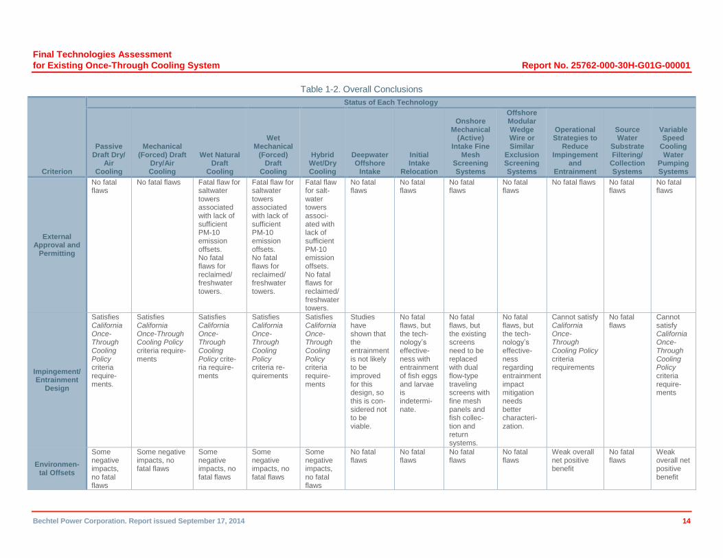
Table 1-2. Overall Conclusions .......................................................................................................................... 14
Table IFMS-1. DCPP Environmental Permit/Approval Cost Assessment: Onshore Mechanical (Active) Intake Fine Mesh Screening System ..................................................................................................... 36
Table WW-1. DCPP Environmental Permit/Approval Cost Assessment: Offshore Modular Wedge Wire Screening System .................................................................................................................................. 73
Table 4.3-1. DCPP Intake Structure Seawater Intake Flows ........................................................................... 81
Table 4.3-2. DCPP Design Ambient Temperatures .......................................................................................... 81
Table 4.3-3. Average Yearly Lost Generation ................................................................................................... 83
Table 4.3-4. Average Unit MW Derating per Year ............................................................................................ 84
Table 4.3-5. Mountain Excavation Quantities ................................................................................................... 91
Final Technologies Assessment
for Existing Once-Through Cooling System Report No. 25762-000-30H-G01G-00001
Bechtel Power Corporation. Report issued September 17, 2014 x
Table CC-1. DCPP Environmental Permit/Approval Cost Assessment: Dry/Air Cooling Technologies—Passive Draft and Mechanical (Forced) Draft ..................................................................................... 130
Table CC-2. DCPP Environmental Permit/Approval Cost Assessment: Wet Cooling Technologies— Natural Draft, Mechanical (Forced) Draft, and Hybrid Wet/Dry (Fresh and Reclaimed Water) ........ 136
Table 7.3-1. Technology Estimate Summary .................................................................................................. 186
Table 7.3.1-1. Explanation of Technology Estimate Summary ...................................................................... 186
List of Attachments
Attachment 1: Phase 1 Report: Independent Third-Party Interim Technical Assessment for the Alternative Cooling Technologies to the Existing Once-Through Cooling System for Diablo Canyon Power Plant
Attachment 2: DCPP Offshore Modular Wedge Wire Screen Field Pilot Testing Plan
Addendum
Addendum to the Independent Third-Party Final Technologies Assessment for the Alternative Cooling Technologies or Modifications to the Existing Once-Through Cooling System for Diablo Canyon Power Plant Addressing the Installation of Saltwater Cooling Towers in the South Parking Lot
List of Drawings
Number Title
25762-110-M5K-YA-00001 Water Balance Diagram
25762-110-M6K-WL-00001 Piping and Instrument Schematic: Circulating Water System, Natural Draft Cooling (Dry)
25762-110-M6K-WL-00002 Piping and Instrument Schematic: Circulating Water System, Mechanical Draft Cooling (Dry)
25762-110-M6K-WL-00003 Piping and Instrument Schematic: Circulating Water System, Natural Draft Cooling (Wet)
25762-110-M6K-WL-00004 Piping and Instrument Schematic: Circulating Water System, Mechanical Draft Cooling (Wet)
25762-110-M6K-WL-00005 Piping and Instrument Schematic: Circulating Water System, Hybrid Cooling Option
25762-110-M6K-WL-00006 Process Flow Schematic – Offshore Wedge Wire Screen
25762-110-M6K-W0-00001 Piping and Instrument Schematic: Desal Supply & Brine Return
25762-110-M6K-WR-00001 Piping and Instrument Schematic: Reclaim Water Supply
25762-110-M6K-WT-00001 Piping and Instrument Schematic: Traveling Screen Wash and Fish Return System
25762-110-M0X-YA-00001 JUOTC Dry Natural Draft CT Option DCPP – Valve List
25762-110-M0X-YA-00002 JUOTC Dry Mechanical Draft CT Option DCPP – Valve List
25762-110-M0X-YA-00003 JUOTC Dry Wet Natural Draft CT Option DCPP – Valve List 25762-110-M0X-YA-00004 JUOTC Wet Mechanical Draft CT Option DCPP – Valve List
25762-110-M0X-YA-00005 JUOTC Hybrid CT Option DCPP – Valve List 25762-110-M0X-YA-00006 JUOTC Study Fine Mesh Option – Diablo Canyon Power Plant – Valve
List
25762-110-M6X-YA-00001 Valve List: JUOTC Study Dry Natural Draft CT Option
25762-110-M6X-YA-00002 Valve List: JUOTC Study Dry Mechanical Draft CT Option
25762-110-M6X-YA-00003 Valve List: JUOTC Study Wet Natural Draft CT Option

Final Technologies Assessment
for Existing Once-Through Cooling System Report No. 25762-000-30H-G01G-00001
Bechtel Power Corporation. Report issued September 17, 2014 xi
Number Title
25762-110-M6X-YA-00004 Valve List: JUOTC Study Wet Mechanical Draft CT Option
25762-110-M6X-YA-00005 Valve List: JUOTC Study Hybrid CT Option
25762-110-M6X-YA-00006 Valve List: JUOTC Study Fine Mesh Option
25762-110-P1K-WL-00010 Circulating Water System Dry Natural Draft Cooling Tower General Arrangement
25762-110-P1K-WL-00011 Circulating Water System Cooling Tower Turbine Building General Arrangement
25762-110-P1K-WL-00012 Circulating Water System Cooling Tower Salt Water Pumps General Arrangement
25762-110-P1K-WL-00013 Circulating Water System Cooling Tower Conduit Removal General Arrangement
25762-110-P1K-WL-00020 Circulating Water System Dry Mechanical Draft Cooling Tower General Arrangement
25762-110-P1K-WL-00030 Circulating Water System Hybrid Draft Cooling Tower General Arrangement
25762-110-P1K-WL-00031 Circulating Water System Cooling Tower Turbine Building General Arrangement
25762-110-P1K-WL-00032 Circulating Water System Cooling Tower Desalination Pumps General Arrangement
25762-110-P1K-WL-00040 Circulating Water System Wet Natural Draft Cooling Tower General Arrangement
25762-110-P1K-WL-00050 Circulating Water System Wet Mechanical Draft Cooling Tower General Arrangement
25762-110-P1K-WL-00060 Circulating Water System Wedge Wire Screens General Arrangement
25762-110-P1K-WL-00061 Circulating Water System Wedge Wire Screens Alternate General Arrangement
25762-110-P1K-WL-00070 Circulating Water System Fine Mesh Traveling Screen General Arrangement
25762-110-P1K-WL-00071 Circulating Water System Fine Mesh Traveling Screen & Fish Return General Arrangement
25762-110-E1K-0000-00001 One Line Diagram: DCPP Circulating Water System Natural Draft Cooling (Dry)
25762-110-E1K-0000-00002 One Line Diagram: DCPP Circulating Water System Mechanical Draft Cooling (Dry)
25762-110-E1K-0000-00003 One Line Diagram: DCPP Circulating Water System Natural Draft Cooling (Wet)
25762-110-E1K-0000-00004 One Line Diagram: DCPP Circulating Water System Mechanical Draft Cooling (Wet)
25762-110-E1K-0000-00005 One Line Diagram: DCPP Circulating Water System Hybrid Cooling Option
25762-110-ERK-WL-00010 Circulating Water System Dry Natural Draft Cooling Tower Raceway Layout
25762-110-ERK-WL-00020 Circulating Water System Dry Mechanical Draft Cooling Tower Raceway Layout
25762-110-ERK-WL-00030 Circulating Water System Hybrid Draft Cooling Tower Raceway Layout
25762-110-ERK-WL-00040 Circulating Water System Wet Natural Draft Cooling Tower Raceway Layout
25762-110-ERK-WL-00050 Circulating Water System Wet Mechanical Draft Cooling Tower Raceway Layout
25762-110-CEK-7200-00001 Two Cooling Tower Arrangement – Excavation Plan
25762-110-CEK-7200-00002 Four Cooling Tower Arrangement – Excavation Plan

Final Technologies Assessment
for Existing Once-Through Cooling System Report No. 25762-000-30H-G01G-00001
Bechtel Power Corporation. Report issued September 17, 2014 xii
Number Title
25762-110-CEK-7200-00003 Two & Four Cooling Tower Arrangement – Excavation Sections
25762-110-CEK-7200-00004 Two Cooling Tower Arrangement – Excavation Plan with USGS TOPO Map
25762-110-CEK-7200-00005 Four Cooling Tower Arrangement – Excavation Plan with USGS TOPO Map

Final Technologies Assessment
for Existing Once-Through Cooling System Report No. 25762-000-30H-G01G-00001
Bechtel Power Corporation. Report issued September 17, 2014 xiii
List of Acronyms and Abbreviations
Term Definition
°C degrees Celsius °F degrees Fahrenheit ac alternating current
ASW auxiliary saltwater ATC regional pollution control district permit to construct bps
Caltrans basis points California Department of Transportation
CAMP Construction Activity Management Plan CARB California Air Resources Board CBOE California Board of Equalization
CCC California Coastal Commission CCR California Code of Regulations
CCRWQCB Central Coast Regional Water Quality Control Board CDFW California Department of Fish and Wildlife CEQA California Environmental Quality Act
CFR (U.S.) Code of Federal Regulations CPUC California Public Utilities Commission CSLC California State Lands Commission
CT cooling tower CW circulating water
CWS CW system dc direct current
DCPP Diablo Canyon Power Plant DCS distributed control system desal desalination
e.g. for example EA Environmental Assessment
EIR Environmental Impact Report EPP environmental protection plan EWS engineering workstation FAA (U.S.) Federal Aviation Administration FAQ frequently asked questions fpm feet per minute fps feet per second
FRP fiber-reinforced polymer FSARU Final Safety Analysis Report Updated
ft feet/foot GDC general design criteria
GO General Order gpm gallons per minute HMI human-machine interface
hp horsepower hr hour
I/O input/output ID identification
JUOTC Joint Utility Once-Through Cooling (Study) kV kilovolt(s)
LAR License Amendment Request LSA Lake and Streambed Alteration
MCC motor control center mg/l milligrams per liter mgd million gallons per day
Final Technologies Assessment
for Existing Once-Through Cooling System Report No. 25762-000-30H-G01G-00001
Bechtel Power Corporation. Report issued September 17, 2014 xiv
Term Definition
MLLW mean lower-low water mm millimeter MV medium voltage
MVA megavolt ampere MWh megawatt hour
NESC National Electrical Safety Code NMFS National Marine Fisheries Service
NOx oxides of nitrogen NPDES National Pollutant Discharge Elimination System
NTP Notice to Proceed OHP (California) Office of Historic Preservation OWS operator workstation
P&I piping and instrumentation PLC programmable logic controller PM particulate matter
PM-10 PM less than 10 microns in diameter PTC regional control district permit to operate
RCRA Resource Conservation and Recovery Act ROG reactive organic gas
SACTI Seasonal/Annual Cooling Tower Impact (Electric Power Research Institute model) SCW service cooling water SLO San Luis Obispo (County)
SLO-APCD SLO Air Pollution Control District SLO-DPB SLO Department of Planning and Building SLO-DPW SLO Department of Public Works SLO-EHS SLO Environmental Health Services
SPCC spill prevention, control, and countermeasure SSC structure, system, or component
SWPPP Storm Water Pollution Prevention Plan SWRCB (California) State Water Resources Control Board
TBM tunnel-boring machine TDS total dissolved solids
TOPO topological tpy tons per year TS technical specification
UPS uninterruptible power supply USACE U.S. Army Corps of Engineers USEPA U.S. Environmental Protection Agency USFWS U.S. Fish and Wildlife Service
USGS U.S. Geological Survey USNRC U.S. Nuclear Regulatory Commission
V volt(s) VI Vendor Information
WWTF Waste Water Treatment Facility
Final Technologies Assessment
for Existing Once-Through Cooling System Report No. 25762-000-30H-G01G-00001
Bechtel Power Corporation. Report issued September 17, 2014 1
1 Executive Summary
This final report describes the findings of the second phase of an assessment of the viability of the technologies noted in the Scope of Work Report prepared for the Diablo Canyon Power Plant (DCPP) by the Nuclear Review Committee to Oversee Special Studies for the Nuclear-Fueled Power Plants Using Once-through Cooling and dated November 7, 2011. The report is in support of the Nuclear Review Committee’s initiative to identify strategies to implement the California Policy on the Use of Coastal and Estuarine Waters for Power Plant Cooling. This strategy would comply with the California Once-Through-Cooling Policy. The Phase 1 report, “Independent Third-Party Interim Technical Assessment for the Alternative Cooling Technologies to the Existing Once-Through Cooling System for Diablo Canyon Power Plant,” was issued on November 5, 2012.
The Phase 1 report evaluates the following technologies for feasibility:
Closed-cycle cooling systems
Deepwater offshore intake
Initial intake relocation
Onshore mechanical (active) intake fine mesh screening systems
Offshore modular wedge wire systems
Operational strategies to reduce impingement and entrainment
Source water substrate filtering/collection systems
Variable-speed cooling water pumping systems
The first-phase evaluation process reviewed each of the technologies without regard for cost against the Nuclear Review Committee evaluation criteria mandated by the Scope of Work document:
First-of-a-kind to scale
External approval and permitting (non-nuclear licensing)
Operability general site conditions
Impingement/entrainment design
Offsetting environmental impacts
Seismic and tsunami issues
Structural
Construction
Maintenance

Final Technologies Assessment
for Existing Once-Through Cooling System Report No. 25762-000-30H-G01G-00001
Bechtel Power Corporation. Report issued September 17, 2014 2
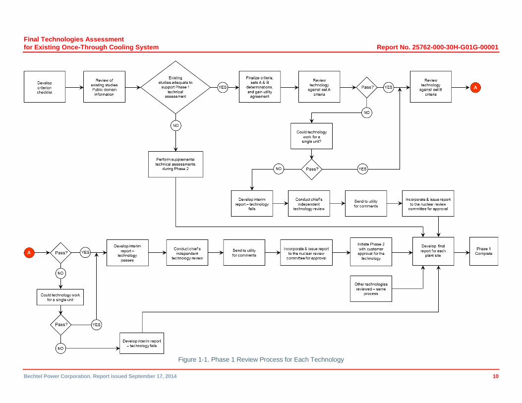
A detailed review of each of the technologies against each of the DCPP criteria has been completed. The evaluation is documented in detail in the Phase 1 final report. Figure 1-1 presents a work flow diagram of the approach used to complete the Phase 1 work.
All of the technologies were reviewed against each of the Phase 1 review criterion, and the Phase 1 final report addressed the feasibility of each of the technologies evaluated for DCPP.
The Phase 1 study concluded that the following technologies were feasible for DCPP subject to the completion of the Phase 2 study:
Closed-cycle cooling systems (except for wet cooling using seawater for makeup)
Onshore mechanical (active) intake fine mesh screening systems
Offshore modular wedge wire systems
In general, the technologies that were found to be not feasible were rejected due to their inability to substantially improve the impingement and/or entrainment characteristics of the intake or, in the case of the closed cooling water technology using saltwater makeup, their inability to permit the technology due to the lack of available PM-10 (particulate matter particles with a diameter of 10 micrometers or less) offsets (salt-related emissions from drift) that would be necessary for an air emissions permit to be granted.
The evaluations examined only the technical feasibility of each technology’s application at DCPP, without consideration of costs, in accordance with the report requirements defined by the State Water Resources Control Board (SWRCB) and PG&E. A more detailed evaluation of which technology/variation is optimum for DCPP, including estimated costs, is performed in Phase 2 of this study.
For technologies that were found to be feasible, the overall finding is that several significant technical and operational challenges are associated with each of the technologies. Those key challenges center on determining the optimum screen and slot sizes to gain the optimum effectiveness in reducing fish egg and larvae entrainment for the once-through cooling; identifying the supply source(s) for makeup water and optimizing the land usage for the closed cooling water options; and managing a permitting process that will be lengthy, complex, and challenging. These issues have been addressed in detail in Phase 2. The overall conclusions of the Phase 1 report are provided in Table 1-1.
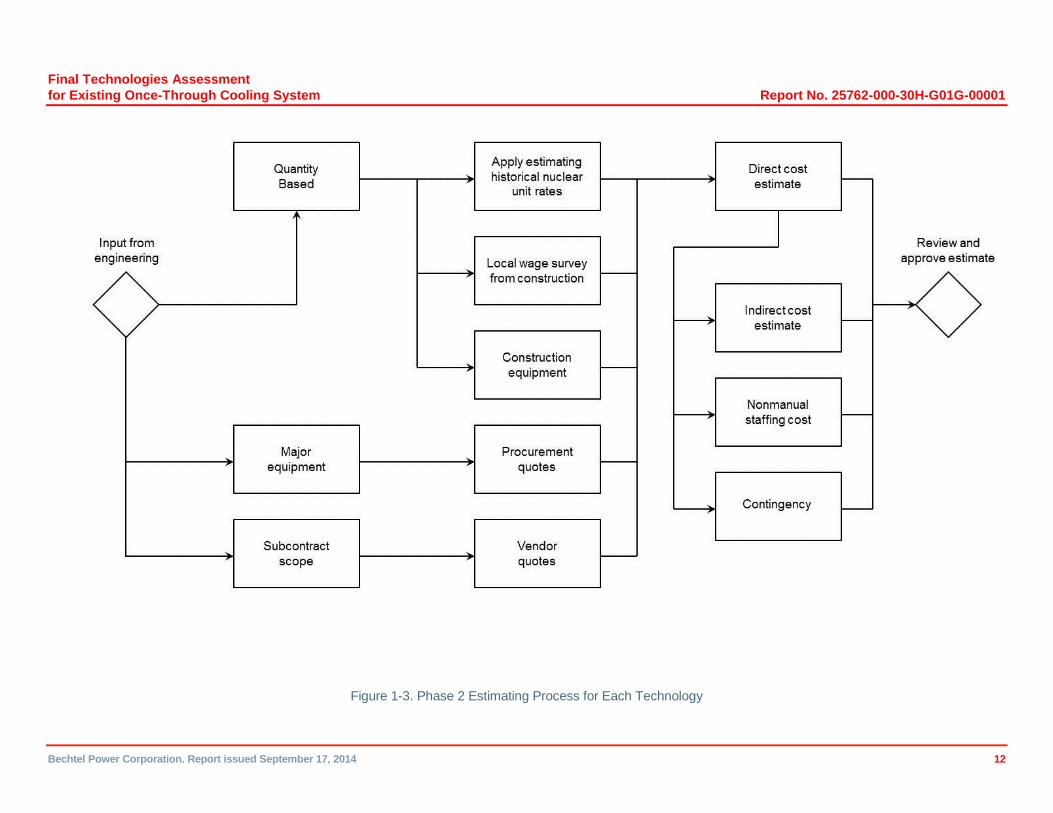
Phase 2 includes completing the nuclear-specific assessment, Criterion 10 (licensing nuclear-specific assessment), and, based on the results of the Criterion 10 assessment, proceeding with the cost and schedule (Criterion 11) assessment for each technology that passes the Criterion 10 evaluation. Figures 1-2 and 1-3 present a work flow diagram of the approach used to complete the Phase 2 work.
The first step of the Phase 2 effort is to complete the Criterion 10 evaluation for each of the technologies to be considered. Criterion 10 is the criteria specified by the Nuclear Review Committee to Oversee Special Studies for the Nuclear-fueled Power Plants Using Once-through Cooling for evaluating the feasibility of alternative technologies to reduce the impingement and entrainment of aquatic organisms in the cooling water. Criterion 10 describes eight areas of U.S. Nuclear Regulatory Commission (USNRC) interest to be assessed:
Seismic issues
Final Technologies Assessment
for Existing Once-Through Cooling System Report No. 25762-000-30H-G01G-00001
Bechtel Power Corporation. Report issued September 17, 2014 3
Operability
Transient analyses
Nuclear fuel (accident analyses)
Single failures
Hydraulic design
Probabilistic risk assessment
Instrumentation controls and alarms
Criterion 10 is a feasibility assessment based on regulatory requirements established by Title 10 of the U.S. Code of Federal Regulations, Part 50, Section 59 (10 CFR 50.59), to determine whether USNRC approval of the alternative technology is required.
The Criterion 10 assessment for the three technologies was completed, and all three selected technologies from Phase 1 passed through the Criterion 10 assessment to Criterion 11.
The Criterion 11 effort included the completion of preliminary designs, development of a Level 2 schedule for each technology, and an additional permitting review focused on the schedule and cost aspects of the required permits identified in Phase 1. These inputs were necessary for the development of the Class 3 estimate (estimate classifications are based on American Association of Cost Engineers International [AACEI] Recommended Practice No. 17R-97, “Cost Estimate Classification System,” and 18R-97, “Cost Estimate Classification System – as applied in Engineering, Procurement and Construction for the Process Industries”). Engineering developed preliminary designs (10 to 15 percent of the key aspects of the designs), quantified equipment sizes, and provided arrangement and quantities for the Estimating department. Technical and cost input for the major equipment was solicited and received from key suppliers. Additionally, tunneling and marine works estimates were received from specialty suppliers and validated by the Estimating department. The schedules for the permitting, design, construction, and commissioning for each technology were developed based on supplier input, industry experience, quantity unit rates, and historical information from previous projects.
For Phase 2, five closed-cycle technology variants and two screening systems selected in Phase 1 were evaluated, all of which were deemed to be technically feasible in Phase 1. The five closed-cycle technologies evaluated were:
Passive draft dry/air cooling
Mechanical (forced) draft dry/air cooling
Wet natural draft cooling
Wet mechanical (forced) draft cooling
Hybrid wet/dry cooling
The Phase 1 assessment also evaluated several potential design alternatives to replace or enhance the existing DCPP shoreline intake structure. Two design alternatives were selected as candidates for further evaluation in the Phase 2 stage of the assessment. These alternatives are:
Final Technologies Assessment
for Existing Once-Through Cooling System Report No. 25762-000-30H-G01G-00001
Bechtel Power Corporation. Report issued September 17, 2014 4
Onshore mechanical (active) intake fine mesh screening system using new dual-flow screens to replace the existing flow-through screens associated with the circulating water (CW) pumps (six screens per unit). Existing flow-through screens associated with the safety-related auxiliary saltwater (ASW) system (one per unit) would not be replaced. The new dual-flow screens would include new fine mesh screen panels and a new fish recovery (collection and return) system.
Offshore modular wedge wire screen assemblies and tunnel to transport the ocean water to the existing intake cove. The existing intake cove opening to the Pacific Ocean would be closed. Two stop log gates would be incorporated in the cove closure to provide an emergency means of supplying water to the plant intake structure in the event of an unforeseen issue with the offshore modular wedge wire screen assemblies or tunnel.
1.1 Criterion 10, Licensing Nuclear-Specific Assessment
10 CFR 50.59 describes the review that is necessary to determine whether a change, test, or experiment in a licensed nuclear power plant must be approved by the USNRC before being implemented.
10 CFR 50.59 allows the licensee to make changes to a plant or its procedures, or to conduct tests or experiments, without prior USNRC approval if the proposed activity does not require a change to the Technical Specifications (TSs) and does not significantly change analyses or their conclusions as documented in the Final Safety Analysis Report Updated (FSARU). This provides assurance that the change, test, or experiment would not adversely affect the ability to safely shut down the plant, to maintain the plant in a safe shutdown condition, and to ensure the ability to maintain offsite radiological consequences of an accident within the limits of 10 CFR Part 100.
As discussed above, Criterion 10 of the Phase 2 assessment is a 10 CFR 50.59 feasibility assessment to determine whether NRC approval of the alternative technology would be required. The assessment considered the eight nuclear design change criteria.
Based on the results of the feasibility assessment and when more detailed engineering information becomes available, the anticipated responses to the eight 10 CFR 50.59 criteria questions for each of the proposed modifications would be NO.
Consequently, subject to the limitations of the Phase 2 assessment information, implementation of the closed-cycle cooling technology, the onshore dual-flow fine mesh screens, or the offshore modular wedge wire screening system design alternatives is believed to not require a License Amendment Request (LAR) in accordance with 10 CFR 50.59. Since this would be a major change to the plant, it is likely that the USNRC would require that it review the design details of the design. It is assumed that any USNRC review required would be completed in parallel with the state permitting process.
Section 3 of the Phase 2 report provides a more detailed discussion of Criterion 10 (Nuclear-specific assessment).
1.2 Criterion 11
The Criterion 11 effort included developing a preliminary/conceptual design for each technology to the extent necessary to support preparation of a Class 3 cost estimate and project implementation schedule. The Criterion 11 effort also included completing preliminary engineering (10 to 15%) of key design aspects that would most influence and support development of the Class 3 cost estimate. The engineering effort included defining equipment

Final Technologies Assessment
for Existing Once-Through Cooling System Report No. 25762-000-30H-G01G-00001
Bechtel Power Corporation. Report issued September 17, 2014 5
sizes, layout arrangements, and quantities to support cost estimate development. Selected major equipment suppliers (cooling towers, pumps, water treatment equipment, large valves, large piping, transformers, and offshore specialty contractors [tunneling and marine works]) were consulted to validate technical data and cost estimates included herein. Key aspects of each of the noted Criterion 11 elements are summarized in the following sections:
1.2.1 Permitting
The initial Phase 1 permitting assessment focused on identifying the applicable (required) permits and approvals for construction and operation of the selected technologies. A comprehensive list of potentially applicable permits and approvals at the federal, California, county, and municipal level (as applicable) was developed.
The subsequent Phase 2 permitting assessment focused on identifying the critical path (longest duration) initial preconstruction permitting processes and the associated project costs. The preconstruction permits are those approvals that directly support site mobilization, physical site access, and initial construction activities associated with the technology option.
The efforts to conduct a successful California Environmental Quality Act (CEQA) review would be the primary critical path permitting process. The CEQA lead agency may be a shared responsibility among a number of key regulatory departments (e.g., San Luis Obispo County, California State Lands Commission [CSLC]). The requisite U.S. Army Corps of Engineers (USACE) Section 404 permit, California Coastal Commission (CCC) Coastal Development Permit, CSLC Lease, and National Pollutant Discharge Elimination System (NPDES) permit modification would have potentially lengthy review processes but would all be essentially bounded by the critical path CEQA/Environmental Impact Report (EIR) review process.
The cost and schedule requirement to secure the major permits applicable to each alternative were developed based on discussions with key relevant regulatory authorities and from associated website resources.
Legal costs associated with managing appeal processes and related litigation were not included. Additionally, the bulk of the potential mitigation costs would be developed through negotiation and are consequently not included in the cost estimate. The cost of compensatory mitigation varies based on the type and scale of impacts to be mitigated and the particular mix of mitigation measures selected to address those impacts. The cost will also vary based on a number of site-specific factors – for example, for a land-based mitigation project, the overall cost will depend on whether land must be purchased or is already available, whether significant grading and site preparation is needed, whether a site has existing sensitive resources that must be protected, or whether other special conditions—such as the presence of contaminants —require special handling, etc. Even so, over the past 10 years or so when California’s coastal power plants retooled or upgraded their generating units, the compensatory mitigation required to address the marine life impacts caused by once-through cooling generally represent no more than five percent of the overall cost of the upgrades. The permitting requirements, along with the associated cost and schedule requirements anticipated for each of the technologies, is summarized in Section 4 of the report. The cost and schedule are addressed in Sections 6 and 7, respectively. Depending of the technology option, the permitting durations range from 3 to 5 years.
1.2.2 Preliminary Design
Section 4 of the report summarizes the preliminary design completed for each of the technology options assessed in the Phase 2 effort: the onshore mechanical (active) intake fine mesh

Final Technologies Assessment
for Existing Once-Through Cooling System Report No. 25762-000-30H-G01G-00001
Bechtel Power Corporation. Report issued September 17, 2014 6
screening system, the offshore modular wedge wire screening system, and the five closed-cycle cooling technology variants.
1.2.2.1 Closed Cooling Highlights of the closed cooling preliminary design development include the following:
Increased condenser pressure results in reduced turbine output. The largest source of lost generation is, as expected, due to reduction in the gross output of a unit due to higher backpressure operation. In addition, the additional auxiliary loads of some of the cooling system options (fans, additional pumping power, etc.) also lead to a reduction in plant net output. The average yearly lost generation (assuming 90% capacity factor) range from 53.6 to 97.3 MW.
The cost of the de-rated output resulting from the installation of these technologies has not been included as part of the installation cost estimate for the technologies.
The ability of the steam turbine to operate at higher condenser backpressures resulting from a closed cooling system was reviewed. The DCPP-specific “protection diagram” provided by PG&E indicates that, for full-load operation, the high backpressure alarm point is 9 inches HgA and the high backpressure trip point is 10.5 inches HgA. Maximum backpressures with wet cooling options will not approach the alarm setting. For the dry cooling options, modification of the steam turbines is considered necessary.
With respect to the major civil/structural effort, the five alternative closed-cycle cooling technologies can be divided into two groups: wet (includes natural draft, mechanical [forced] draft, and hybrid variants) and dry (includes natural draft and mechanical [forced] draft variants). Preliminary civil designs were prepared to size major structures such as cooling tower foundations, new pumphouses and header boxes, the storage pond, desalination and water treatment plant foundations, and mountain excavation quantities.
It will be necessary to excavate a portion of the mountains immediately north of the DCPP power block to an elevation of 115’ to provide the space needed to build the new cooling towers. The number of cooling towers needed is technology specific. The location of the new cooling towers has been chosen carefully to provide the most economical solution and to preclude impact to the nearby archeological site. No trade studies have been completed to evaluate the cost differential related to increasing the tower base elevation, thereby reducing excavation, and completing duct modifications so that they could withstand the higher pressure. Tower locations are shown on the plant site rendering included as Figure 1-4. The tower pictured was supplied courtesy of SPX Cooling Technologies Inc. The leveled area required at elevation 115’ for the two cooling towers arrangement is approximately 62 acres and for the four cooling towers arrangement is approximately 109 acres. The estimated excavation quantities for the two-tower and four-tower general arrangements, with 7-percent haul ramps, is approximately 190 million cubic yards and 316 million cubic yards respectively.
230 kV Line Relocation: The existing two-circuit 230 kV line that provides the main source of offsite power for DCPP and the northernmost 500 kV circuit that transmits DCPP Units 1and 2 electrical output offsite via the Gates transmission intertie require rerouting. Three double -circuit high voltage transmission towers of the existing 230 kV line and one single-circuit high voltage tower of the existing 500 kV single-circuit line must be moved. The relocated line would consist of four new towers, the first being just outside the 230 kV substation on the opposite side of Pecho Valley Road.
Final Technologies Assessment
for Existing Once-Through Cooling System Report No. 25762-000-30H-G01G-00001
Bechtel Power Corporation. Report issued September 17, 2014 7
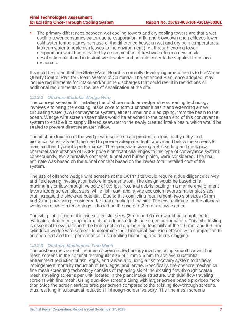
The primary differences between wet cooling towers and dry cooling towers are that a wet cooling tower consumes water due to evaporation, drift, and blowdown and achieves lower cold water temperatures because of the difference between wet and dry bulb temperatures. Makeup water to replenish losses to the environment (i.e., through cooling tower evaporation) would be provided by a combination of freshwater from a new onsite desalination plant and industrial wastewater and potable water to be supplied from local resources.
It should be noted that the State Water Board is currently developing amendments to the Water Quality Control Plan for Ocean Waters of California. The amended Plan, once adopted, may include requirements for intake and/or brine discharges that could result in restrictions or additional requirements on the use of desalination at the site.
1.2.2.2 Offshore Modular Wedge Wire The concept selected for installing the offshore modular wedge wire screening technology involves enclosing the existing intake cove to form a shoreline basin and extending a new circulating water (CW) conveyance system, either tunnel or buried piping, from the basin to the ocean. Wedge wire screen assemblies would be attached to the ocean end of this conveyance system to enable it to supply filtered seawater to the newly created intake basin, which would be sealed to prevent direct seawater inflow.
The offshore location of the wedge wire screens is dependent on local bathymetry and biological sensitivity and the need to provide adequate depth above and below the screens to maintain their hydraulic performance. The open sea oceanographic setting and geological characteristics offshore of DCPP pose significant challenges to this type of conveyance system; consequently, two alternative concepts, tunnel and buried piping, were considered. The final estimate was based on the tunnel concept based on the lowest total installed cost of the system.
The use of offshore wedge wire screens at the DCPP site would require a due diligence survey and field testing investigation before implementation. The design would be based on a maximum slot flow-through velocity of 0.5 fps. Potential debris loading in a marine environment favors larger screen slot sizes, while fish, egg, and larvae exclusion favors smaller slot sizes that increase the blockage potential. Due to this conflicting requirement, two slot sizes (6 mm and 2 mm) are being considered for in-situ testing at the site. The cost estimate for the offshore wedge wire system technology is based on the use of a 2-mm slot size screen.
The situ pilot testing of the two screen slot sizes (2 mm and 6 mm) would be completed to evaluate entrainment, impingement, and debris effects on screen performance. This pilot testing is essential to evaluate both the biological and engineering feasibility of the 2.0-mm and 6.0-mm cylindrical wedge wire screens to determine their biological exclusion efficiency in comparison to an open port and their performance in controlling biofouling and debris clogging.
1.2.2.3 Onshore Mechanical Fine Mesh The onshore mechanical fine mesh screening technology involves using smooth woven fine mesh screens in the nominal rectangular size of 1 mm x 6 mm to achieve substantial entrainment reduction of fish, eggs, and larvae and using a fish recovery system to achieve impingement mortality reduction of fish, eggs, and larvae. Specifically, the onshore mechanical fine mesh screening technology consists of replacing six of the existing flow-through coarse mesh traveling screens per unit, located in the plant intake structure, with dual-flow traveling screens with fine mesh. Using dual-flow screens along with larger screen panels provides more than twice the screen surface area per screen compared to the existing flow-through screens, thus resulting in substantial reduction in through-screen velocity. The fine mesh screens

Final Technologies Assessment
for Existing Once-Through Cooling System Report No. 25762-000-30H-G01G-00001
Bechtel Power Corporation. Report issued September 17, 2014 8
selected would reduce velocity from about 1.95 fps to 1 fps. In addition, a fish recovery system would be incorporated to collect fish, eggs, and larvae impinged on the new dual-flow screens. Eggs and larvae impinged on the fine mesh screens and fish collected inside the fish bucket would be removed, collected, and returned back to the sea via a new fish return pipeline.
Even though this technology does not comply with the maximum 0.5 fps through-screen velocity for impingement mortality reduction described in the California Once-Through Cooling Policy rules, the inclusion of a fish recovery system provides the alternative mitigation measures that support compliance with the California Once-Through Cooling Policy requirements.
In order for the plant to operate reliably, an automatic trash raking system is needed to remove large debris trapped on the trash racks located upstream of the plant traveling screens. The cost of designing and constructing an automatic trash removal system has not been estimated as part of this effort.
1.2.3 Schedule and Cost Estimate
Based on the preliminary design data and the conceptual approaches developed for construction and startup of the selected options, a Level 1 schedule and Class 3 cost estimate was developed for each. Details regarding the construction approach are provided in Section 5 of the report and the schedule and cost estimate discussions are provided in Sections 6 and 7, respectively.
Bechtel considered the concerns provided to the Nuclear Review Committee following Phase 1 on January 23, 2013, by Mr. Laurence G. Chaset for the Friends of the Earth and the January 23, 2013, letter from Mr. Noah Long and Mses. Angela Kelley, Sarah Sikich, and Sara Aminzadeh representing the Natural Resources Defense Council, Heal the Bay, and the California Coastkeeper Alliance. The concerns brought up in these letters were considered and addressed as appropriate as part of the Phase 2 effort.
1.3 Phase 2 Results
The overall findings of the report are provided in Table 1-1 below, which presents the costs and schedule estimates for each technology. The cost data is a Class 3 cost estimate as defined by the Association for the Advancement of Cost Engineering International (AACEI), the estimate includes 20% contingency and an expected accuracy range of -20% to +30%. Section 7 of the report includes a detailed discussion of the cost estimate development, including qualifications and assumptions, and exclusions.
Table 1-1. Technology Cost and Schedule Summary
Technology Cost
in Millions Schedule Duration
in Years
Closed-Cycle Cooling
Mechanical (Forced) Draft Dry/Air Cooling $10,200 – $14,134 13
Passive Draft Dry/Air Cooling $10,104 – $14,045 13
Wet Mechanical (Forced) Draft Cooling $8,567 – $11,647 14
Wet Natural Draft Cooling $10,185 – $14,112 14
Hybrid Wet/Dry Cooling $8,654 – $11,723 13
Final Technologies Assessment
for Existing Once-Through Cooling System Report No. 25762-000-30H-G01G-00001
Bechtel Power Corporation. Report issued September 17, 2014 9
Technology Cost
in Millions Schedule Duration
in Years
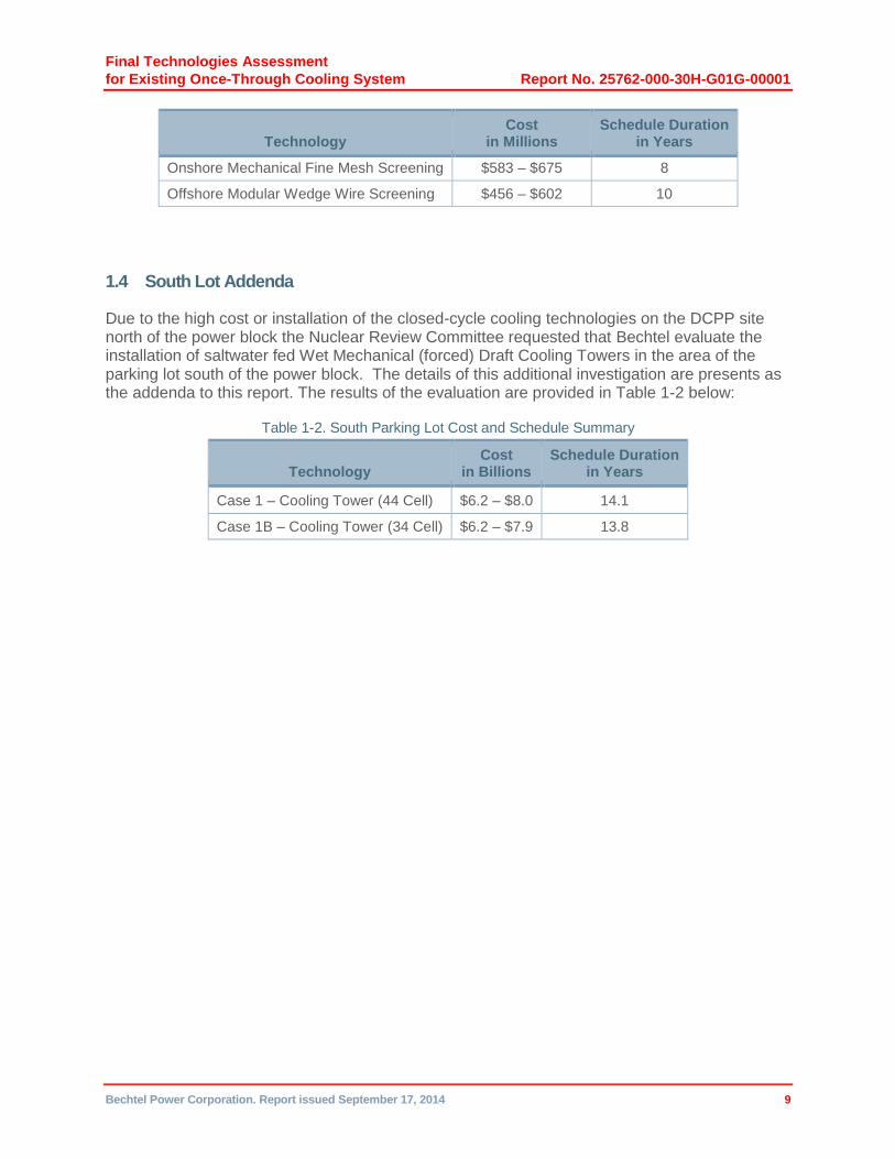
Onshore Mechanical Fine Mesh Screening $583 – $675 8
Offshore Modular Wedge Wire Screening $456 – $602 10
1.4 South Lot Addenda
Due to the high cost or installation of the closed-cycle cooling technologies on the DCPP site north of the power block the Nuclear Review Committee requested that Bechtel evaluate the installation of saltwater fed Wet Mechanical (forced) Draft Cooling Towers in the area of the parking lot south of the power block. The details of this additional investigation are presents as the addenda to this report. The results of the evaluation are provided in Table 1-2 below:
Table 1-2. South Parking Lot Cost and Schedule Summary
Technology Cost
in Billions Schedule Duration
in Years
Case 1 – Cooling Tower (44 Cell) $6.2 – $8.0 14.1
Case 1B – Cooling Tower (34 Cell) $6.2 – $7.9 13.8
Final Technologies Assessment
for Existing Once-Through Cooling System Report No. 25762-000-30H-G01G-00001
Bechtel Power Corporation. Report issued September 17, 2014 10
Figure 1-1. Phase 1 Review Process for Each Technology

Final Technologies Assessment
for Existing Once-Through Cooling System Report No. 25762-000-30H-G01G-00001
Bechtel Power Corporation. Report issued September 17, 2014 11
Figure 1-2. Phase 2 Review Process for Each Technology
Final Technologies Assessment
for Existing Once-Through Cooling System Report No. 25762-000-30H-G01G-00001
Bechtel Power Corporation. Report issued September 17, 2014 12
Figure 1-3. Phase 2 Estimating Process for Each Technology

Final Technologies Assessment
for Existing Once-Through Cooling System Report No. 25762-000-30H-G01G-00001
Bechtel Power Corporation. Report issued September 17, 2014 13
Figure 1-4. Plant Site Rendering Showing the Wet Natural Draft Configuration
Final Technologies Assessment
for Existing Once-Through Cooling System Report No. 25762-000-30H-G01G-00001
Bechtel Power Corporation. Report issued September 17, 2014 14
Table 1-2. Overall Conclusions
Criterion
Status of Each Technology
Passive Draft Dry/
Air Cooling
Mechanical (Forced) Draft
Dry/Air Cooling
Wet Natural Draft
Cooling
Wet Mechanical
(Forced) Draft
Cooling
Hybrid Wet/Dry Cooling
Deepwater Offshore
Intake
Initial Intake
Relocation
Onshore Mechanical
(Active) Intake Fine
Mesh Screening Systems
Offshore Modular Wedge Wire or Similar
Exclusion Screening Systems
Operational Strategies to
Reduce Impingement
and Entrainment
Source Water
Substrate Filtering/
Collection Systems
Variable Speed
Cooling Water
Pumping Systems
External Approval and
Permitting
No fatal flaws
No fatal flaws Fatal flaw for saltwater towers associated with lack of sufficient PM-10 emission offsets. No fatal flaws for reclaimed/ freshwater towers.
Fatal flaw for saltwater towers associated with lack of sufficient PM-10 emission offsets. No fatal flaws for reclaimed/ freshwater towers.
Fatal flaw for salt-water towers associ-ated with lack of sufficient PM-10 emission offsets. No fatal flaws for reclaimed/ freshwater towers.
No fatal flaws
No fatal flaws
No fatal flaws
No fatal flaws
No fatal flaws No fatal flaws
No fatal flaws
Impingement/ Entrainment
Design
Satisfies California Once-Through Cooling Policy criteria require-ments.
Satisfies California Once-Through Cooling Policy criteria require-ments
Satisfies California Once-Through Cooling Policy crite-ria require-ments
Satisfies California Once-Through Cooling Policy criteria re-quirements
Satisfies California Once-Through Cooling Policy criteria require-ments
Studies have shown that the entrainment is not likely to be improved for this design, so this is con-sidered not to be viable.
No fatal flaws, but the tech-nology’s effective-ness with entrainment of fish eggs and larvae is indetermi-nate.
No fatal flaws, but the existing screens need to be replaced with dual flow-type traveling screens with fine mesh panels and fish collec-tion and return systems.
No fatal flaws, but the tech-nology’s effective-ness regarding entrainment impact mitigation needs better characteri-zation.
Cannot satisfy California Once-Through Cooling Policy criteria requirements
No fatal flaws
Cannot satisfy California Once-Through Cooling Policy criteria require-ments
Environmen-tal Offsets
Some negative impacts, no fatal flaws
Some negative impacts, no fatal flaws
Some negative impacts, no fatal flaws
Some negative impacts, no fatal flaws
Some negative impacts, no fatal flaws
No fatal flaws
No fatal flaws
No fatal flaws
No fatal flaws
Weak overall net positive benefit
No fatal flaws
Weak overall net positive benefit

Final Technologies Assessment
for Existing Once-Through Cooling System Report No. 25762-000-30H-G01G-00001
Bechtel Power Corporation. Report issued September 17, 2014 15
Criterion
Status of Each Technology
Passive Draft Dry/
Air Cooling
Mechanical (Forced) Draft
Dry/Air Cooling
Wet Natural Draft
Cooling
Wet Mechanical
(Forced) Draft
Cooling
Hybrid Wet/Dry Cooling
Deepwater Offshore
Intake
Initial Intake
Relocation
Onshore Mechanical
(Active) Intake Fine
Mesh Screening Systems
Offshore Modular Wedge Wire or Similar
Exclusion Screening Systems
Operational Strategies to
Reduce Impingement
and Entrainment
Source Water
Substrate Filtering/
Collection Systems
Variable Speed
Cooling Water
Pumping Systems
First-of-Kind-to-Scale
No fatal flaws.
No fatal flaws No fatal flaws
No fatal flaws
No fatal flaws
Not evalu-ated
No fatal flaws
No fatal flaws
No fatal flaws
Not evaluated Fatal flaw – this technology has not been used for a water supply system of this size and is impracti-cal.
Not evaluated
Operability of General Site Conditions
No fatal flaws
No fatal flaws No fatal flaws
No fatal flaws
No fatal flaws
Not evaluated
No fatal flaws.
No fatal flaws
No fatal flaws
Not evaluated Low reliability and ever-decreasing lateral efficiency make this technology a fatal flaw.
Not evaluated
Seismic and Tsunami Issues
No fatal flaws
No fatal flaws No fatal flaws
No fatal flaws
No fatal flaws
Not evaluated
No fatal flaws
No fatal flaws
No fatal flaws
Not evaluated No fatal flaws
Not evaluated
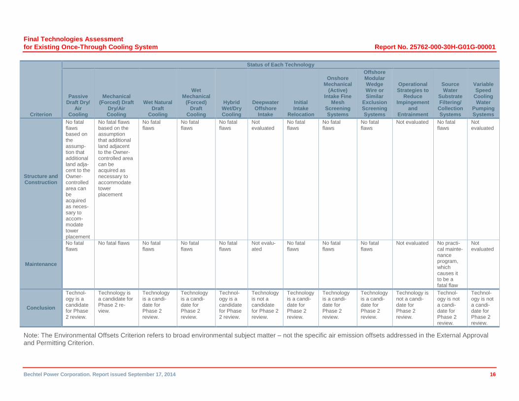
Final Technologies Assessment
for Existing Once-Through Cooling System Report No. 25762-000-30H-G01G-00001
Bechtel Power Corporation. Report issued September 17, 2014 16
Criterion
Status of Each Technology
Passive Draft Dry/
Air Cooling
Mechanical (Forced) Draft
Dry/Air Cooling
Wet Natural Draft
Cooling
Wet Mechanical
(Forced) Draft
Cooling
Hybrid Wet/Dry Cooling
Deepwater Offshore
Intake
Initial Intake
Relocation
Onshore Mechanical
(Active) Intake Fine
Mesh Screening Systems
Offshore Modular Wedge Wire or Similar
Exclusion Screening Systems
Operational Strategies to
Reduce Impingement
and Entrainment
Source Water
Substrate Filtering/
Collection Systems
Variable Speed
Cooling Water
Pumping Systems
Structure and Construction
No fatal flaws based on the assump-tion that additional land adja-cent to the Owner-controlled area can be acquired as neces-sary to accom-modate tower placement
No fatal flaws based on the assumption that additional land adjacent to the Owner-controlled area can be acquired as necessary to accommodate tower placement
No fatal flaws
No fatal flaws
No fatal flaws
Not evaluated
No fatal flaws
No fatal flaws
No fatal flaws
Not evaluated No fatal flaws
Not evaluated
Maintenance
No fatal flaws
No fatal flaws No fatal flaws
No fatal flaws
No fatal flaws
Not evalu-ated
No fatal flaws
No fatal flaws
No fatal flaws
Not evaluated No practi-cal mainte-nance program, which causes it to be a fatal flaw
Not evaluated
Conclusion
Technol-ogy is a candidate for Phase 2 review.
Technology is a candidate for Phase 2 re-view.
Technology is a candi-date for Phase 2 review.
Technology is a candi-date for Phase 2 review.
Technol-ogy is a candidate for Phase 2 review.
Technology is not a candidate for Phase 2 review.
Technology is a candi-date for Phase 2 review.
Technology is a candi-date for Phase 2 review.
Technology is a candi-date for Phase 2 review.
Technology is not a candi-date for Phase 2 review.
Technol-ogy is not a candi-date for Phase 2 review.
Technol-ogy is not a candi-date for Phase 2 review.
Note: The Environmental Offsets Criterion refers to broad environmental subject matter – not the specific air emission offsets addressed in the External Approval and Permitting Criterion.
Final Technologies Assessment
for Existing Once-Through Cooling System Report No. 25762-000-30H-G01G-00001
Bechtel Power Corporation. Report issued September 17, 2014 17
2 Introduction
Bechtel Power Corporation’s “Independent Third-Party Interim Technical Assessment for the Alternative Cooling Technologies or Modifications to the Existing Once-Through Cooling System for Diablo Canyon Power Plant,” Report No. 25762-000-30R-G01G-00009, issued on November 5, 2012 (Phase 1 report) (Attachment 1), describes the findings of Phase 1 of an assessment of the viability of the technologies noted in the Scope of Work Report prepared for the Diablo Canyon Power Plant (DCPP) by the Nuclear Review Committee to Oversee Special Studies for the Nuclear-Fueled Power Plants Using Once-through Cooling and dated November 7, 2011. The report is in support of the Nuclear Review Committee initiative to identify strategies to implement the California Policy on the Use of Coastal and Estuarine Waters for Power Plant Cooling. This strategy is intended to comply with the California Once-Through-Cooling Policy. The Phase 1 report concludes that the following technologies are technically feasible (based on assessment checklist Criteria 1 through 9) for DCPP:
Onshore mechanical (active) intake fine mesh screening systems
Offshore modular wedge wire systems
Closed-cycle cooling systems (five closed-cycle cooling variations, including hybrids)
Phase 2 of the effort includes completing the nuclear-specific assessment (assessment checklist Criterion 10) and then, based on the results of the Criterion 10 assessment, proceeding with the cost and schedule (Criterion 11) assessment for each technology that passes the Criterion 10 evaluation. The Criterion 11 effort includes developing a preliminary design for each technology to the extent necessary to prepare the cost estimate and complete the implementation schedule assessment.
This report contains the Criterion 10 assessment for the three technologies selected from Phase 1 and a description of the preliminary engineering effort performed to obtain adequate technical information to be used in preparing the cost estimate and schedule to implement each of those technologies.
3 Licensing Nuclear-Specific Assessment (Criterion 10)
The final Phase 1 report on alternate cooling technologies or modifications to the existing once-through cooling systems for DCPP evaluated eight technologies. Of the eight, the following three were approved by the Nuclear Review Committee for further consideration in Phase 2:
Onshore mechanical (active) intake fine mesh screening systems
Offshore modular wedge wire systems
Closed-cycle cooling systems
The first step in the Phase 2 effort is to complete the Criterion 10 evaluation for each of the technologies to be considered. This evaluation is provided in Section 4 for each technology.
Criterion 10 is among the criteria specified by the Nuclear Review Committee to Oversee Special Studies for the Nuclear-fueled Power Plants Using Once-through Cooling for evaluating the feasibility of alternative technologies to reduce the impingement and entrainment of aquatic organisms in the cooling water. Criterion 10 describes eight areas of U. S. Nuclear Regulatory Commission (USNRC) interest to be assessed:
Final Technologies Assessment
for Existing Once-Through Cooling System Report No. 25762-000-30H-G01G-00001
Bechtel Power Corporation. Report issued September 17, 2014 18
Seismic issues
Operability
Transient analyses
Nuclear fuel (accident analyses)
Single failures
Hydraulic design
Probabilistic risk assessment
Instrumentation controls and alarms
Criterion 10 is a feasibility assessment based on regulatory requirements established by 10 CFR 50.59, to determine whether USNRC approval of the alternative technology is required.
3.1 Alternatives for Closed-Cycle Cooling Technology
The closed-cycle cooling technology reviewed in the Phase 1 assessment replaces the existing once-through cooling with a closed loop in which the cooling water is continuously circulated. The heat picked up by the circulating water (CW) in the main condenser is dissipated to the general environment (the atmosphere) in cooling towers. Five variants of closed-cycle cooling technologies were evaluated. The assessment concluded that replacing the DCPP once-through cooling systems with any of the five variants of closed-cycle cooling technologies evaluated is technically feasible. Makeup water to replenish losses to the environment (i.e., through cooling tower evaporation) would be provided by a combination of freshwater from a new onsite desalination plant and industrial wastewater and potable water to be supplied from local resources. Therefore, all five variants were recommended as candidates for further evaluation in the Phase 2 stage of the assessment.
The five closed-cycle cooling technologies evaluated were:
1. Passive draft dry/air cooling
2. Mechanical (forced) draft dry/air cooling
3. Wet natural draft cooling
4. Wet mechanical (forced) draft cooling
5. Hybrid wet/dry cooling
Natural draft towers rely on convection currents to move air through the tower. These currents are created by the difference in air density between the inside of the tower, where the air is warmer as it picks up heat from the CW, and the outside of the tower, where the air is cooler at general ambient temperature. Forced draft towers use fans to drive the air through the tower.
Dry towers use finned tubes for heat transfer. When the CW passes through these finned tubes, its heat content is transferred by conduction and convection to the air passing over the fins/tubes. In a wet tower, the CW is sprayed though nozzles into direct contact with the air passing through the tower and is cooled by evaporation as it falls into the tower basin. A hybrid tower uses both wet and dry methods in a stacked arrangement, with the dry section on top to eliminate the visible plume generated by the wet section.
Final Technologies Assessment
for Existing Once-Through Cooling System Report No. 25762-000-30H-G01G-00001
Bechtel Power Corporation. Report issued September 17, 2014 19
3.2 Alternatives to Existing Intake Technology
The Phase 1 assessment also evaluated several potential design alternatives to replace or enhance the existing DCPP shoreline intake structure. Two design alternatives were selected as candidates for further evaluation in the Phase 2 stage of the assessment. These alternatives are:
1. Onshore mechanical (active) intake fine mesh screening systems using new dual-flow screens to replace the existing flow-through screens associated with the CW pumps (six per unit). Existing flow-through screens associated with the safety-related auxiliary saltwater (ASW) system (one per unit) would not be replaced. The new dual-flow screens would include new fine mesh screen panels to replace the existing coarse mesh screens plus a new fish recovery (collection and return) system for each new dual-flow traveling water screen. Additional water required for the larger dual-flow screens and fish recovery system would be provided by additional pumps supplementing the existing screen wash system. New pumps would be located in the bays serviced by the new screens.
2. Offshore modular wedge wire or similar exclusion screening systems using offshore wedge wire screen assemblies and piping to transport the ocean water to the existing intake cove. The existing intake cove opening to the Pacific Ocean would be closed. Two stop log gates would be incorporated in the cove closure to provide an emergency means of supplying water to the plant intake structure in the event of an unforeseen issue with the offshore wedge wire screen assemblies and piping. It would be extremely unlikely that these gates would ever be required because the water demand of the service water system after an accident would be very low versus the design capacity of the wedge wire array, but there may be a need for NRC review of this feature.
3.2.1 10 CFR 50.59
10 CFR 50.59 describes the review that is necessary to determine whether a change, test, or experiment in a licensed nuclear power plant must be approved by the USNRC before being implemented.
10 CFR 50.59 allows the licensee to make changes to a plant or its procedures, or to conduct tests or experiments, without prior USNRC approval if the proposed activity does not require a change to the Technical Specifications (TSs) and does not significantly change analyses or their conclusions as documented in the Final Safety Analysis Report Updated (FSARU). This provides assurance that the change, test, or experiment would not adversely affect the ability to safely shut down the plant, to maintain the plant in a safe shutdown condition, and to ensure the ability to maintain offsite radiological consequences of an accident within the limits of 10 CFR Part 100. More specifically, the change, test, or experiment cannot:
1. Result in more than a minimal increase in the frequency of occurrence of an accident previously evaluated in the FSARU
2. Result in more than a minimal increase in the likelihood of occurrence of a malfunction of a structure, system, or component (SSC) important to safety previously evaluated in the FSARU
3. Result in more than a minimal increase in the consequences of an accident previously evaluated in the FSARU

Final Technologies Assessment
for Existing Once-Through Cooling System Report No. 25762-000-30H-G01G-00001
Bechtel Power Corporation. Report issued September 17, 2014 20
4. Result in more than a minimal increase in the consequences of a malfunction of an SSC important to safety previously evaluated in the FSARU
5. Create the possibility of an accident of a type different from any previously evaluated in the FSARU
6. Create the possibility of a malfunction of an SSC important to safety with a result different from any previously evaluated in the FSARU
7. Result in a design basis limit for a fission product barrier as described in the FSARU being exceeded or altered
8. Result in a departure from a method of evaluation described in the FSARU used in establishing the design bases or in the safety analyses
3.2.2 FSARU
The FSARU provides a summary level description of the plant SSCs, including the controls, monitoring, and protective features that ensure that the plant can be safely operated and controlled under various normal, abnormal, and accident conditions. It also provides a discussion of normal, abnormal, and accident operations, including analyses of a spectrum of transients and accidents and the results of those analyses. The focus is on the safety-related SSCs and their supporting features that provide the ability to safely control and shut down the plant, and to maintain it in a safe shutdown condition, under probable and extreme conditions.
The DCPP FSARU describes the circulating water system (CWS) in Section 10.4.5. The Design Bases section, 10.4.5.1, states that the system provides cooling water to condense steam entering the main condenser and that it also serves the intake coolers, condensate cooler, and service cooling water (SCW) heat exchangers. The CWS Safety Evaluation section, 10.4.5.3, states that the CW pumps are not required for the (nuclear) safety of the units but that provisions are incorporated in the design to ensure their dependable operation for reliable operation of the plant. In Section 9.2.1, the SCW system is described as a closed system used to cool non-safety-related equipment in the secondary portion of the plant. CWS acceptability is based on meeting the requirements of General Design Criteria (GDC) 4 as it relates to design provisions provided to accommodate the effects of discharging water that may result from a failure of a component or piping in the CWS. The requirements of GDC 4 are met when the CWS design includes provisions to accommodate the effects of discharging water that may result from a failure of a component or piping in the CWS. Consequently, Section 10.4.5.4 provides a flooding analysis discussion and details of the CWS design and operating pressures and the connection to the main condenser, noting that significant flooding of the turbine building with seawater due to CWS failure is a highly improbable event. It also describes a flooding analysis based on the failure to properly secure a waterbox manway cover. In Section 9.2.5, the ultimate heat sink is identified as the Pacific Ocean, which is the source of cooling water to the non-safety-related CWS and SCW heat exchangers and to the safety-related ASW system. The availability of the ultimate heat sink to provide cooling when required under severe conditions is discussed in Section 2.4.11.6.
3.3 Assessment of Closed-Cycle Cooling Technology
The following is an assessment of the five alternative closed-cycle cooling system heat transfer technologies that were determined to be technically feasible in the Phase 1 assessment. The closed-cycle cooling technology designs can use wet, dry, or hybrid wet/dry cooling methods. Dry cooling technologies require minimal makeup water to account for system leaks/losses after the closed system is initially charged. Wet cooling technologies, because of their operating

Final Technologies Assessment
for Existing Once-Through Cooling System Report No. 25762-000-30H-G01G-00001
Bechtel Power Corporation. Report issued September 17, 2014 21
principle, require a greater volume of makeup water to compensate for evaporation, blowdown, and drift losses. As such, makeup requirements vary depending on the cycles of concentration at which the wet cooling towers are operated. For the purposes of this assessment, both dry and wet closed-cycle cooling technologies are discussed together.
The five closed-cycle cooling technologies evaluated are:
1. Passive draft dry/air cooling
2. Mechanical (forced) draft dry/air cooling
3. Wet natural draft cooling
4. Wet mechanical (forced) draft cooling
5. Hybrid wet/dry cooling
3.3.1 Seismic
The seismic requirements for a design change can be summarized as ensuring that seismically induced structural or functional failure of any new SSCs would not adversely affect safety-related SSCs. Direct effects, such as falling on a safety-related SSC, and indirect effects, such as functional failure affecting the ability of a safety-related SSC to perform its safety function, must be either demonstrated as acceptable or prevented from happening.
The new cooling towers would be located remote from the power block and safety-related SSCs so that their partial or total structural failure would not adversely affect any safety-related functions. The new pumphouse(s) for the new CW pumps would be located within the existing power block area and would be sufficiently separated from safety-related SSCs as to pose no direct or indirect adverse effects.
Functional failures of the closed-cycle cooling system would not be expected to adversely affect safety-related SSCs or functions since the safety-related cooling requirements of the ASW system would continue to be met since they would not be functionally modified by this change. The existing supports and piping associated with the component cooling water heat exchangers and interfacing ASW system components are seismically designed and would not be adversely affected by the proposed modifications.
3.3.2 Operability
Replacement of once-through cooling with closed-cycle cooling would increase the operating temperature of the CW and increase main condenser backpressure. This would result in decreased turbine efficiency and reduced electrical output from the main generator. It may be necessary to modify the low-pressure turbine so that it can operate at higher condenser backpressures. The higher condenser backpressure decreases the margin to alarm set points; however, sufficient margins would be maintained to provide assurance that there would be no significant increase in the probability of turbine trips. It is intended that when the closed-cycle cooling system design is finalized, there would be sufficient margin between the turbine trip set point and higher condenser pressure so that the probability of more frequent turbine trips would not increase significantly.
3.3.3 Transient Analyses
As mentioned in Section 3.3.2, the closed-cycle cooling technology alternatives would increase the operating temperature of the CW and increase main condenser backpressure. However,
Final Technologies Assessment
for Existing Once-Through Cooling System Report No. 25762-000-30H-G01G-00001
Bechtel Power Corporation. Report issued September 17, 2014 22
sufficient margin between new operating backpressures and the turbine trip point would be maintained to minimize the potential for increased turbine trips. As part of the design of the closed-cycle cooling system, a pressure transient analysis would be performed to ensure that adequate design parameters are identified for piping and associated components. No transient analyses associated with safe shutdown of the plant are expected to be adversely affected by the closed-cycle cooling technology.
3.3.4 Nuclear Fuel (Accident Analyses)
3.3.4.1 Auxiliary Saltwater System The safety-related ASW system is not affected by this modification. The CWS and the SCW system do not provide cooling to any component required for safe shutdown. The CW pumps are not required for the safety of the units. A complete shutdown of the SCW system would not affect safe shutdown of the reactor. The replacement of the once-through cooling with closed-cycle cooling would result in an increase in CW temperature. This increase is not expected to adversely affect FSARU accident analyses since these systems serve no safety-related functions.
3.3.4.2 Single Failure The conversion of the once-through cooling system to closed-cycle cooling design technologies would not adversely affect the safety-related function of the ASW system since this system is not expected to be modified. Closed-cycle cooling is not expected to adversely affect any single failures evaluated in the FSARU because the CWS and the SCW system have no safety-related functions, nor do they support any safety-related functions. There would be four CW pumps per unit in lieu of the current two per unit. Operation of the four pumps in the closed-cycle cooling system in lieu of two once-through pumps would not result in additional adverse single failures. The forced draft cooling towers would have fans but, due to the number of fans, single fan failures should have negligible effects on CWS operation and performance. Dependable pump operation in the closed-cycle cooling system would remain a high priority to ensure reliable plant operation.
3.3.5 Hydraulic Design
The hydraulic design for closed-cycle cooling would be developed to ensure efficient and reliable hydraulic performance of the non-safety-related CWS. The safety-related ASW system remains functionally unchanged in the final design.
3.3.6 Probabilistic Risk Assessment
The replacement of non-safety-related once-through cooling with closed-cycle cooling is not expected to adversely affect the probabilistic risk assessment. The CWS has no safety-related function, nor does it support any safety-related functions. The safety-related ASW system remains unchanged in the final design.
3.3.7 Instrumentation, Controls, and Alarms
The design of the instrumentation, controls, and alarms for the closed-cycle cooling would provide monitoring and indication for flows, temperatures, pressures, motor currents, etc., to provide operators with required evidence of system operating conditions and trends, similar to the existing once-through cooling.
3.4 Assessment of Intake Technology Alternatives
The following is an assessment of the two intake technology design alternatives that were selected in Phase 1 as candidates for further evaluation:
Final Technologies Assessment
for Existing Once-Through Cooling System Report No. 25762-000-30H-G01G-00001
Bechtel Power Corporation. Report issued September 17, 2014 23
Alternative 1–Onshore Mechanical (Active) Intake Fine Mesh Screening System
Alternative 2–Offshore Modular Wedge Wire or Similar Exclusion Screening Systems
Alternative 1 is discussed in Section 3.4.1, and Alternative 2 is discussed in Section 3.4.2.
3.4.1 Alternative 1–Onshore Mechanical (Active) Intake Fine Mesh Screening System
3.4.1.1 Seismic The seismic requirements for the new dual-flow fine mesh screening system, including the fish recovery system, would be same as the existing intake structure seismic design requirements. The safety-related SSCs associated with the ASW system would remain unchanged. The replacement of flow-through screens with dual-flow type screens would not pose an adverse impact from a seismic perspective.
The intake and discharge structures do not perform an active safety-related function. They are seismically designed and indirectly support a safety-related function by structurally supporting the ASW pumps, associated once-though screens, and related piping located at the intake structure and the component cooling water system’s heat exchangers located in the turbine building and related piping located at the discharge structure. The final design for the new intake and discharge structures for the closed-cycle cooling should ensure that seismically induced structural or functional failure of any new SSCs would not adversely affect safety-related SSCs.
3.4.1.2 Operability The dual-flow screens and fine mesh screen panels would be sized to reduce the overall velocity across the screening system. The existing common traveling screen servicing the intake bays associated with each unit’s safety-related ASW pumps would not be modified. Therefore, modification of the traveling screens on the non-safety-related intake bays would not adversely affect the operation of the safety-related ASW system. It is intended that the new screen modifications would not adversely affect any SSCs serving the safety-related ASW pumps. The significant reduction of mesh opening (from the current 9.53 mm down to 1 to 2 mm), would result in a substantially higher debris load on the screen panels. This much higher debris loading on the screen panels must be removed to avoid overloading or collapsing the screen panels. The new design would provide the required removal capability. For the fish recovery system to be effective, fish, eggs, and larvae must be continuously removed. The new rotating dual-flow screen design would need to be continuously operated and be equipped with variable speed drive to increase the screen rotation speed as needed due to changing debris loading.
3.4.1.3 Transient Analyses The dual-flow screens and fine mesh screen panels would be sized to ensure a low pressure drop across the overall system and provide required flow to the CW pumps. No modification would be made to the traveling screens servicing the intake bays associated with the safety-related ASW system. It is intended that the new fine mesh screen modifications would not adversely affect any SSCs serving the safety-related ASW system. No transient analyses associated with safe shutdown of the plant would be adversely affected by the new fine mesh screen modifications.
3.4.1.4 Nuclear Fuel (Accident Analyses) The CWS and the SCW system do not provide cooling to any component required for safe shutdown. The CW pumps are not required for the safety of the units. A complete shutdown of the SCW system would not affect safe shutdown of the reactor. The conversion of the existing flow-through screens to dual-flow type would not affect the screens serving the safety-related ASW pumps. Consequently, the final design for the dual-flow screens and fine mesh screen panels is not expected to adversely affect FSARU accident analyses.

Final Technologies Assessment
for Existing Once-Through Cooling System Report No. 25762-000-30H-G01G-00001
Bechtel Power Corporation. Report issued September 17, 2014 24
3.4.1.5 Single Failure The traveling screens associated with the safety-related ASW system would not be modified. The conversion of the existing flow-through screens to dual-flow screens for the intake bays servicing the CW pumps would not adversely affect any single failures evaluated in the FSARU because the CWS and the SCW system have no safety-related functions, nor do they support any safety-related functions. The final designs for the shoreline intake structure, including the dual-flow screens and fine mesh screen panels, would ensure that the single failure requirements for the safety-related ASW and component cooling water systems remain unaffected.
3.4.1.6 Hydraulic Design As indicated in Section 3.4.1.3, the dual-flow screens and fine mesh screen panels would be sized to ensure a low pressure drop across the overall system. The final design would also consider the increased pressure drop effects due to postulated blockages of the fine mesh screen panels. It is intended that the new screen modifications, including the fish recovery system, would not adversely affect any SSCs serving the safety-related ASW pumps.
3.4.1.7 Probabilistic Risk Assessment The modifications to the shoreline intake structure, including the dual-flow screens and fine mesh screen panels, are not expected to adversely affect the probabilistic risk assessment since the overall design philosophy remains unchanged.
3.4.1.8 Instrumentation, Controls and Alarms The design of the instrumentation, controls, and alarms for the fine mesh dual-flow screens, including the fish recovery system, would provide for monitoring of flows, temperature, pressures, motor currents, etc., to provide operators with required evidence of system operating conditions and trends.
3.4.2 Alternative 2–Offshore Modular Wedge Wire or Similar Exclusion Screening Systems
3.4.2.1 Seismic The offshore modular wedge wire system, in conjunction with the closure of the intake cove, would functionally replace the existing cove opening. The offshore modular wedge wire screening system would be seismic and non-safety-related. The two stop-log gates located in the cove closure would be seismic and safety-related to ensure that a second source of water is available for the ASW system. Because of the offshore, submerged location of the modular wedge wire screening system, the final design would accommodate both seismic design loads and wave forces that would be encountered in the open sea environment.
The remote offshore location of the modular wedge wire screening system, including the piping manifolds, vertical shaft, and breakwater enclosure, would ensure that seismically induced structural or functional failure of any new SSCs would not adversely affect safety-related SSCs.
3.4.2.2 Operability The offshore modular wedge wire system would functionally replace the intake cove opening. The offshore modular wedge wire screening system would be sized to ensure a low pressure drop across the overall system and a low velocity across the wedge wire screens. The offshore screen/piping design would be based on a low pressure drop across the wedge wire screen’s intake system and a large piping or tunnel diameter to minimize the added offshore component head loss compared to the existing shoreline intake system. The wedge wire screen slots would be sized to provide a balance between the reduction in impingement/entrainment and the required additional maintenance as a result of their susceptibility to clogging. Extensive in-situ testing would be conducted during the project’s detailed design phase to demonstrate that the
Final Technologies Assessment
for Existing Once-Through Cooling System Report No. 25762-000-30H-G01G-00001
Bechtel Power Corporation. Report issued September 17, 2014 25
screen slot size selected is not prone to blockage in the marine environment. The frequency of inspection and cleaning would be directly proportional to the seasonal marine growth and debris condition at the screens. Emergency openings (i.e., stop-log gates) would be incorporated in the breakwater extension to ensure a continual water supply to the ASW pumps to maintain their safety function. The final design for the offshore modular wedge wire screening system would not increase the risk for unit trips.
3.4.2.3 Transient Analyses The offshore modular wedge wire screening system would be sized to ensure a low pressure drop across the overall system. This would ensure that the ultimate heat sink would remain available to provide cooling water to the non-safety-related CWS and SCW system. It is intended that the new offshore modular wedge wire screening system modifications would not adversely affect any SSCs serving the safety-related ASW pumps. No transient analyses associated with safe shutdown of the plant are expected to be adversely affected by the new offshore modular wedge wire screening system modifications.
3.4.2.4 Nuclear Fuel (Accident Analyses) The CWS and the SCW system do not provide cooling to any component required for safe shutdown. The CW pumps are not required for the safety of the units. A complete shutdown of the SCW system would not affect safe reactor shutdown. The installation of the offshore modular wedge wire screening system would not adversely affect the screens serving the safety-related ASW pumps. Seismically designed and safety-related dual stop-log gates located in the cove closure would provide a second source of water to the ASW system. The safety-related saltwater cooling system is not affected by this modification because it remains in the original once-through configuration. Consequently, the final design for the offshore modular wedge wire screening system is not expected to adversely affect FSARU accident analyses.
3.4.2.5 Single Failure The installation of the new offshore modular wedge wire screening system is not expected to adversely affect any single failures evaluated in the FSARU because the CWS and the SCW system have no safety-related functions, nor do they support any safety-related functions. The final design for the offshore modular wedge wire screening system would ensure that the single failure requirements for the safety-related ASW and component cooling water systems remain unaffected. Emergency openings (i.e., stop-log gates) would be incorporated in the breakwater extension to ensure a continual water supply to the ASW pumps to maintain their safety function.
3.4.2.6 Hydraulic Design As indicated in Sections 3.4.2.2 and 3.4.2.3, the offshore modular wedge wire screening system would be sized to ensure a low pressure drop across the overall system. The final design would also consider the blockage of the screens due to seasonal marine growth and debris. The complete stoppage of flow may result in vacuum conditions inside the screen that could damage the screen. This would be considered as part of the hydraulic design. It is intended that the new offshore modular wedge wire screening system would not adversely affect any SSCs serving the safety-related ASW pumps.
3.4.2.7 Probabilistic Risk Assessment The installation of the new offshore modular wedge wire screening system is not expected to adversely affect the probabilistic risk assessment.
3.4.2.8 Instrumentation, Controls and Alarms No new instrumentation is provided as part of the offshore wedge wire screening system. Existing plant instrumentation would provide means to monitor plant intake flow, levels,
Final Technologies Assessment
for Existing Once-Through Cooling System Report No. 25762-000-30H-G01G-00001
Bechtel Power Corporation. Report issued September 17, 2014 26
temperatures, etc., to provide operators with the required evidence of system operating conditions and trends.
3.5 Conclusion—Criterion 10 Assessment
Criterion 10 is a 10 CFR 50.59 feasibility assessment to determine whether USNRC approval of the alternative technology would be required. Eight nuclear design change criteria were considered in the assessment:
1. Seismic issues
2. Operability
3. Transient analyses
4. Nuclear fuel (accident analyses)
5. Single failures
6. Hydraulic design
7. Probabilistic risk assessment
8. Instrumentation controls and alarms
Based on the results of the feasibility assessment and when more detailed engineering information becomes available, the anticipated responses to the following eight 10 CFR 50.59 criteria questions for each of the proposed modifications would be NO:
1. Result in more than a minimal increase in the frequency of occurrence of an accident previously evaluated in the FSARU?
2. Result in more than a minimal increase in the likelihood of occurrence of a malfunction of an SSC important to safety previously evaluated in the FSARU?
3. Result in more than a minimal increase in the consequences of an accident previously evaluated in the FSARU?
4. Result in more than a minimal increase in the consequences of a malfunction of an SSC important to safety previously evaluated in the FSARU?
5. Create the possibility of an accident of a type different from any previously evaluated in the FSARU?
6. Create the possibility of a malfunction of an SSC important to safety with a result different from any previously evaluated in the FSARU?
7. Result in a design basis limit for a fission product barrier as described in the FSARU being exceeded or altered?
8. Result in a departure from a method of evaluation described in the FSARU used in establishing the design bases or in the safety analyses?

Final Technologies Assessment
for Existing Once-Through Cooling System Report No. 25762-000-30H-G01G-00001
Bechtel Power Corporation. Report issued September 17, 2014 27
Consequently, subject to the limitations of the Phase 2 assessment information, implementation of the closed-cycle cooling technology, the onshore dual-flow fine mesh screens, or the offshore modular wedge wire screening system design alternatives is believed to not require a License Amendment Request (LAR) in accordance with 10 CFR 50.59. Since this would be a major change to the plant, it is likely that the USNRC would require that it review the design details of the change. It is assumed that any USNRC review required would be completed in parallel with the state permitting process.
3.6 Facility Operating License/Technical Specifications
The DCPP Facility Operating Licenses and TSs were reviewed to identify all requirements associated with the once-through cooling cycle SSCs. Specifically, the review focused on the need to revise any TS requirements associated with the CWS, SCW system, ASW system, and ultimate heat sink. This review did not identify the need to revise any TS requirements that would require a LAR. However, the TS Bases discussion for the ultimate heat sink (B 3.7.9) may need to be updated to describe the closed-cycle cooling technology. Revisions to the TS Bases do not require prior USNRC approval.
3.7 Environmental Protection Plan (Non-Radiological)
The DCPP Facility Operating Licenses include a facility non-radiological environmental protection plan (EPP) as Appendix B, Environmental Protection Plan (Nonradiological). 10 CFR 50.59 does not apply to changes to the plan because a method for control of plan changes is described in the plan itself. Changes are submitted to the USNRC as license amendments and would include an assessment of the environmental impact and supporting justifications. However, in accordance with Section 3.3 of the plan, changes in plant design or operation and performance of tests or experiments required to achieve compliance with other federal, state, or local environmental regulations would not be subject to prior USNRC approval.
4 Preliminary Design Development
Ultimately, the onshore mechanical (active) intake fine mesh screening system, the offshore modular wedge wire screening, and the closed-cycle cooling technologies were selected for the Phase 2 assessment. This section presents a description of the preliminary design development for each of these three technologies.
4.1 Onshore Mechanical (Active) Intake Fine Mesh Screening Technology
The onshore mechanical fine mesh screening technology involves using smooth woven fine mesh screens in the nominal rectangular size of 1 mm x 6 mm to achieve substantial entrainment reduction of fish, eggs, and larvae and using a fish recovery system to achieve impingement mortality reduction of fish, eggs, and larvae. Specifically, the onshore mechanical fine mesh screening technology consists of replacing six of the existing flow-through coarse mesh traveling screens per unit, located in the plant intake structure, with dual-flow traveling screens with fine mesh. Using dual-flow screens along with larger screen panels provides more than twice the screen surface area per screen compared to the existing flow-through screens, thus resulting in substantial reduction in through-screen velocity. The fine mesh screens selected would reduce velocity from about 1.95 fps to 1 fps. In addition, a fish recovery system would be incorporated to collect fish, eggs, and larvae impinged on the new dual-flow screens. A fish bucket attached to the bottom of each screen panel would hold the fish along with sufficient water as the screen moves upward. Eggs and larvae impinged on the fine mesh screens and fish collected inside the fish bucket would be removed, collected, and returned back to the sea via a new fish return pipeline. The increased debris loading on the fine mesh would be mitigated by the increased screen surface area, higher screen rotating speed, and
Final Technologies Assessment
for Existing Once-Through Cooling System Report No. 25762-000-30H-G01G-00001
Bechtel Power Corporation. Report issued September 17, 2014 28
continuous screen operation (rotation). The existing screen wash (spray) system would be modified to fit the new dual-flow screens with a dual-pressure spray system (low pressure spray of 5 to 10 psig for fish, egg, and larvae removal and high pressure spray of approximately 60 psig for debris removal) and supplemented to provide the additional flow capacity needed to support the requirements of the larger screens for trash and fish, egg, and larvae recovery.
Even though this technology does not comply with the maximum 0.5 fps through-screen velocity for impingement mortality reduction described in the California Once-Through Cooling Policy rules, the inclusion of a fish recovery system provides the alternative mitigation measures that support compliance with the California Once-Through Cooling Policy requirements. Similarly, implementation of onshore mechanical fine mesh screening technology substantially reduces entrainment loss and marks significant improvement over the current DCPP situation since it currently has a 100-percent administrative loss of fish, eggs, and larvae due to the very large mesh opening of 9.5 mm on the existing flow-through traveling water screens.
In order for the plant to operate reliably, an automatic trash raking system is needed to remove large debris trapped on the trash racks located upstream of the plant traveling screens. Although the plant has a design for an automatic raking system, it cannot be installed on the existing structure due to the installation of the required plant security system. Currently, plant personnel manually remove large debris. This inefficient method of trash removal at times causes the plant to reduce output until the cleaning can be completed. The cost of designing and constructing an automatic trash removal system has not been estimated as part of this effort but would have to be added if the onshore mechanical fine mesh screening technology is selected for implementation.
No safety-related systems are affected by this modification.
4.1.1 Hydraulic Evaluation of the Dual-Flow Screen Retrofit
As shown in General Arrangement Drawing 25762-110-P1K-WL-00070, the rotating axis of the new dual-flow screens would be rotated 90 degrees from the current flow-through screen design. Three screens serve each CW pump. The general flow characteristics of a dual-flow screen and its comparison to a flow-through screen design were described in the Phase 1 report, Section 3.5.
Based on the available space in the existing pump intake, the replacement screen panel width can be up to 14 feet, which is significantly larger than the existing 10-foot screen width. As with the dual-flow screen design, CW would pass through both the ascending and descending faces of the screen. This flow, combined with the larger screen panel width, would reduce the average through-screen velocity to about 1 fps from the existing 1.95 fps at low water level. The significant reduction in average through-screen velocity to 1 fps, combined with continuous screen operation at up to a high speed of 40 fpm, provides an available screen carrying capacity that enables finer mesh screen panels, up to 1 mm size, to be used to mitigate an expected increase of debris loading on the fine mesh screen panels. An increase of debris loading is obvious since the debris in the size range of 1 mm to 9.5 mm would otherwise pass the existing screen panels but would be blocked by the new screens with 1 mm size. In addition, to further mitigate the debris issue, a prerequisite to the fine-mesh, dual-flow screen retrofit is to convert the existing manual cleaning of the upstream trash racks to an installed automatic raking system that would effectively clean larger size debris, such as kelp.
Due to the orientation of the dual-flow screen, the flow exiting the screen is through the middle section of the screen well. This results in a more concentrated flow pattern leaving each screen. Even though the exit velocity would be higher than that for the existing flow-through screen, hydraulic evaluation indicates that the current CW pump suction arrangement should tolerate

Final Technologies Assessment
for Existing Once-Through Cooling System Report No. 25762-000-30H-G01G-00001
Bechtel Power Corporation. Report issued September 17, 2014 29
this velocity increase, primarily due to the elaborate use of the formed suction inlet design, a smooth and accelerating turn toward the pump impeller, as shown in Section A of General Arrangement Drawing 25762-110-P1K-WL-00070. However, to confirm this hydraulic assessment, a physical CW pump intake model test should be conducted by a reputable hydraulic laboratory during the final design process if this technology is selected for implementation. Depending on the testing results, it may be necessary to add a surface beam/baffle downstream of the dual-flow screen exits.
4.1.2 Justification of Selecting 1 mm Fine Mesh Opening
Fine mesh screens fitted to the traveling water screens belong to the active “collect and transfer” design with a mesh size sufficiently small to minimize entrainment loss of fish, eggs, and larvae. As background information, the existing DCPP traveling water screens have a mesh size of 9.5 mm, which essentially allows all fish, eggs, and larvae to pass through and suffer a 100-percent administrative entrainment loss during plant operation. Any reduction in the number of fish, eggs, and larvae entrained presents an improvement over the current situation of total entrainment loss.
Section 4.2.4 of the Phase 1 report provides supporting information on the selection of the rectangular mesh with an effective mesh opening of 1 or 2 mm to achieve improvement in entrainment loss reduction. Additional information was made available to Bechtel during the Phase 2 assessment that indicates a need for an effective mesh opening of 1 mm.
A Tenera report, Report Supplement: Length-Specific Probabilities of Screen Entrainment of Larval Fishes Based on Head Capsule Measurements (Incorporating NFPP Site-Specific Estimates), dated October 29, 2013 (Reference 3), provides screen entrainment probabilities calculated for six slot/screen widths (0.75 mm, 1 mm, 2 mm, 3 mm, 4 mm, and 6 mm) based on the mathematical relationships between overall notochord length of the larvae and the parameters of head capsule width and depth, for fish larvae samples collected at eight power plants along the central and southern California coastline. In addition, the report also provides a DCPP site-specific entrainment reduction estimate based on site-specific samples collected during the period of October 1996 through June 1999. The report conservatively assumes that all available samples approach the screen head on and discounts likely fish larvae impingement on the screen panel from the notochord length side.
The samples were collected near the intakes of the eight power plants, including samples collected at DCPP from 1996 to 1999. In this report, a length-specific probability of entrainment for each slot/screen size was calculated for both head width and depth. The probability of entrainment for each notochord length was determined as the larger value of either the head width entrainment probability or the head depth probability. The probabilities were calculated over a size range that approximately corresponds to the range of the lengths of larvae that would be potentially entrainable.
Out of 15 species evaluated, Tenera reported that average percentage reductions in mortality by slot/screen width are as follows:
Slot Size 0.75 mm 1 mm 2 mm 3 mm 4 mm 5 mm
Average Percentage Reduction in Mortality 77.1% 67.6% 34.6% 15.8% 7.8% 1.8%
It would not be possible to use a 0.75 mm slot/screen size because that size would provide insufficient screen surface area based on the available space of the existing pump intake; furthermore, the net result would be only a small percentage reduction in mortality compared to
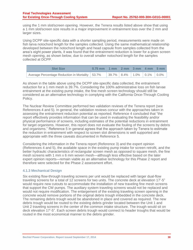
Final Technologies Assessment
for Existing Once-Through Cooling System Report No. 25762-000-30H-G01G-00001
Bechtel Power Corporation. Report issued September 17, 2014 30
using the 1 mm slot/screen opening. However, the Tenera results listed above show that using a 1 mm slot/screen size results in a major improvement in entrainment loss over the 2 mm and larger sizes.
Using DCPP site-specific data with a shorter sampling period, measurements were made on fish larva notochord length for the samples collected. Using the same mathematical relationship developed between the notochord length and head capsule from samples collected from the area’s eight power plants, it was found that the entrainment reduction is lower for a given screen mesh opening, as shown below, due to overall smaller notochord length for the samples collected at DCPP.
Slot Size 0.75 mm 1 mm 2 mm 3 mm 4 mm 5 mm
Average Percentage Reduction in Mortality 53.7% 39.7% 8.4% 1.0% 0.1% 0.0%
As shown in the table above using the DCPP site-specific data collected, the entrainment reduction for a 1 mm mesh is 39.7%. Considering the 100% administrative loss on fish larvae entrainment at the existing pump intake, the fine mesh screen technology should still be considered as an alternative technology in complying with the California Once-Through Cooling Policy.
The Nuclear Review Committee performed two validation reviews of the Tenera report (see References 4 and 5). In general, the validation reviews concur with the approaches taken in assessing the entrainment reduction potential as reported. Reference 4 concluded that “the report effectively provides information that can be used in evaluating the feasibility and/or physical performance of screens, including estimates of the potential reductions in entrainment for target organisms. However, this report does not evaluate the fouling of the screens by debris and organisms.” Reference 5 in general agrees that the approach taken by Tenera to estimate the reduction in entrainment with respect to screen slot dimensions is well supported and appropriate with the three caveats documented in Reference 5.
Considering the information in the Tenera report (Reference 3) and the expert opinion (References 4 and 5), the available space in the existing pump intake for screen retrofit, and the better hydraulic characteristics of rectangular screen mesh as opposed to square mesh, the fine mesh screens with 1 mm x 6 mm woven mesh—although less effective based on the later expert opinion reports—remain viable as an alternative technology for this Phase 2 report and therefore were selected for the Phase 2 assessment effort.
4.1.3 Mechanical Design
Six existing flow-through traveling screens per unit would be replaced with larger dual-flow traveling screens for a total of 12 screens for two units. The concrete deck at elevation 17’-5” would require new cutouts to accommodate the installation of new traveling fine mesh screens that support the CW pumps. The auxiliary system traveling screens would not be replaced and would not require modification. The enlargement of the existing traveling screen opening in the concrete would remove portions of the original debris trough imbedded in the concrete deck. The remaining debris trough would be abandoned in place and covered as required. The new debris trough would be routed to the existing debris grinder located between the Unit 1 and Unit 2 traveling screens in the center of the common intake structure. The trough would sit on deck elevation 17’-5”. Each screen debris trough would connect to header troughs that would be routed in the most economical manner to the debris grinder.
Final Technologies Assessment
for Existing Once-Through Cooling System Report No. 25762-000-30H-G01G-00001
Bechtel Power Corporation. Report issued September 17, 2014 31
A second trough above the debris trough is provided for fish, egg, and larvae collection. A fish deflector sill would be installed to bridge the gap between the screen panel and fish trough to keep fish, eggs, and larvae from falling through the gap. Each fish trough would be collected into a common trough and routed to the ocean north of the existing intake structure.
Two additional screen wash water pumps, one for each unit, would be provided to supplement the existing three pumps. The new Unit 1 screen wash pump and strainer would be located in front of CW pump 1-2 at elevation –2’-1”. The new Unit 2 screen wash pump and strainer would be located in front of CW pump 2-1 at elevation –2’-1”. This location provides the most space to accommodate these components. The new pump’s suction nozzle would extend into the CW forebay at a depth equal to 1’-0” below the extreme low tide water level (–2’-4”). The new pump nozzle would be approximately 10 feet above the CW pump suction nozzle and 4 feet forward of the CW pump suction nozzle. The two pump discharge nozzles would be routed to a new extension of an existing 24-inch header. This flanged header pipe can be extended at each end to accommodate the new equipment. The Unit 1 and Unit 2 automatic strainers would receive their suction from the 24-inch header. The strainers would be connected to a common 16-inch-diameter header that would distribute its flow to each Unit 1 and Unit 2 fine mesh screen. This existing piping is about 12 feet overhead. This allows the strainer basket to be removed and the new screen pumps to be installed. The new traveling fine mesh screens would be connected to existing 6-inch piping. This configuration was chosen to reduce cost by using existing piping and supports. It eliminates unnecessary core drilling of additional penetrations of the upper deck. The location of the new screen wash pumps and strainers is near a perimeter wall and allows the surrounding space to be used as a laydown area for other equipment repair or placement.
Six-inch y-strainers would be added at each new traveling screen spray header. Individual isolation and pressure control valves would be provided at each traveling screen. Mechanical equipment associated with this technology is summarized in the equipment list, 25762-110-M0X-YA-00006. New valves being added are summarized in the valve list, 25762-110-M6X-YA-00006.
Two major screen suppliers were contacted to obtain the technical information needed to perform the preliminary design. These suppliers assisted in maximizing the screen surface area that could be installed in the existing structure—which resulted in minimizing the through-screen velocity to about 1 fps—in conjunction with using a slot/screen size (nominal 1 mm x 6 mm) that would effectively collect fish, eggs, and larvae. The suppliers also helped to identify the design requirements for a recovery system for fish, eggs, and larvae impinged on the screen panels. The suppliers provided screen performance information; preliminary physical drawings; equipment weights; electrical requirements; spray wash flow requirements for debris and fish, egg, and larvae removal; and guidance on transporting fish, eggs, and larvae. The screens would be equipped with variable speed drives (with a range of about 10 to 40 fpm). The materials of construction would be primarily stainless steel with fiberglass splash housing, troughs, spray piping, and fish return trough. Cathodic protection would be provided by replaceable sacrificial anodes with an estimated life of 5 years.
A piping and instrumentation (P&I) schematic (25762-110-M6K-WT-00001) was developed for the screen wash spray system to show its piping sizes and components as well as how it would interface with the existing screen wash system. Lists of new valves and inline piping components were generated to identify the required scope to complete the system. Existing piping is a lined piping; new piping would be fiberglass. Valves would be ductile iron or duplex stainless steel, depending on size and service.
Final Technologies Assessment
for Existing Once-Through Cooling System Report No. 25762-000-30H-G01G-00001
Bechtel Power Corporation. Report issued September 17, 2014 32
General arrangement drawings (25762-110-P1K-WL-00070, -00071) were developed to identify the new location for the dual-flow traveling screens, screen wash pumps, and screen wash strainers and the routing of the fish return trough.
The following assumptions are associated with the mechanical portion of the design:
There has been no significant degradation to the existing screen wash pump performance.
The existing spray piping is reusable (has not deteriorated).
A bar rack debris removal system would be added to the system if this technology is selected for implementation.
4.1.4 Control System Design
Control systems and equipment have been designed in accordance with the instrumentation and controls shown on P&I Schematic 25762-110-M6K-WT-00001 and the equipment described in the mechanical section of this report. A new vendor-supplied local control panel with operator interface would be provided for each new traveling screen and associated screen wash system. The existing traveling screen panel would be decommissioned and removed. The new panels would be installed at the locations of the old traveling screen panels in the Unit 1 and Unit 2 electrical equipment rooms located in the existing intake structure. New panels would also be provided for the two existing ASW traveling screen systems that are otherwise not being replaced or modified.
A new control panel would be furnished for the two new screen wash pumps. This panel would be located in the general vicinity of the existing screen wash control panel. The two new automatic backwash strainers would each have vendor-supplied control panels located in the general vicinity of the strainers.
Alarms would be generated by the local controlling device or programmable logic controller (PLC) to indicate potential loss of operating equipment. Pump, motor, strainer, and screen/spray system trouble or malfunction indications would be provided to operators via common alarms as per existing design.
A pressure control valve would be provided at each new traveling screen to control the screen wash spray water pressure. Local pressure indicators would also be furnished downstream of each pressure control valve. A pressure transmitter and local pressure gauge would be provided downstream of each automatic backwash strainer. The pressure transmitters would interface with the dual-flow traveling screen and screen wash spray controls. A differential pressure gauge would be provided across each automatic backwash strainer and would interface with the strainer controls.
Existing intake level instrumentation would be retained and interfaced with the new traveling screen controls.
4.1.5 Civil Design
The Civil discipline has performed preliminary engineering to support the development of the price and schedule for adding replacement screens and making related modifications to the existing intake structure.
Replacing the through-flow screens with larger dual-flow screens necessitates making structural modifications to the intake structure. The modifications would be to the concrete deck, where the dual-flow screens would be situated at a 90-degree angle relative to the existing screens.

Final Technologies Assessment
for Existing Once-Through Cooling System Report No. 25762-000-30H-G01G-00001
Bechtel Power Corporation. Report issued September 17, 2014 33
Each new screen requires a larger east–west footprint. The new screens would be anchored to the walls of the existing intake structure.
4.1.5.1 Description of Civil Structure The existing single-flow screens are supported on the intake structure, and fish and debris are collected, sent to the grinder, and then discharged to the ocean north of the plant, beyond the breakwater.
To accommodate the new dual-flow screens, the intake structure deck would be modified by cutting it to provide larger openings.
The fish recovery system would be a fiber-reinforced-polymer (FRP) pipe that would run along the new screens above the existing concrete deck. It would direct fish, eggs, and larvae to the ocean through a vertical shaft, a tunnel, and a concrete conduit, thereby securing their release to the ocean. Refer to General Arrangement Drawing 25762-110-P1K-WL-0071 for details of the modifications and the addition of the fish recovery system.
4.1.5.2 Seismic Classification The intake structure is a Seismic Design Class II reinforced concrete building housing and supporting Design Class I equipment. Thus, the structure is designed to avoid collapse that would impair equipment operation.
The fish recovery system is designed as Seismic Category II, and its failure would not affect plant operations during a seismic event.
4.1.5.3 Summary of Civil Deliverables Civil modifications are planned to accommodate the replacement of the existing single-flow screens with new dual-flow screens as follows:
1. Modify the existing intake structure:
a. Modify the deck by increasing existing opening sizes to accommodate each new dual-flow screen (opening sizes increase in the east–west direction).
b. Design anchors for the screens.
c. Rebuild the voids (between the existing opening and the new screens).
d. Cut two openings in the existing slab for the installation of the new pumps.
2. Install the new fish recovery system:
a. Provide FRP pipe to recover fish, eggs, and larvae and direct them to the ocean.
b. Provide a support system for the FRP pipe.
c. Drill a vertical shaft in the ground.
d. Drill a horizontal tunnel.
e. Provide a concrete conduit and a header at the end of the concrete conduit.
The following assumptions are associated with the Civil portion of the design:
The concrete deck and the intake structure are adequate for new slab openings.
The existing trash trough is abandoned in place.
No other modifications are required in the intake structure.
Final Technologies Assessment
for Existing Once-Through Cooling System Report No. 25762-000-30H-G01G-00001
Bechtel Power Corporation. Report issued September 17, 2014 34
The traveling screens will be designed so that the fish return will be at elevation 23’-0” to allow a 4-foot minimum clearance from the concrete deck level at elevation 17.5’ and to provide sufficient elevation to obtain the proper flow for the fish return line.
The new raking system for trash racks would be designed separately at a future date if this technology is selected for implementation.
The safety classification of the new structure in front of the existing intake structure is Seismic Category I and Design Class II (similar to the existing intake structure classification).
No underground utilities are required for the fish recovery tunnel and Construction can tunnel through the rock area.
No new fence is required (minor existing fence modification may be required, but were not considered in this estimate).
4.1.6 Electrical Design
The overall additional electrical load for this modification is approximately 140 hp, which is relatively minimal. The existing power distribution system has the required capacity for the incremental load. The existing 480 V intake load center switchgear would feed the loads to the extent possible. Existing feeders would be used to swap the existing screen loads with the new screen loads.
The instrumentation list and quantities were the primary inputs for the electrical design. Input data used to develop the quantities were:
Mechanical equipment lists depicting the pumphouse power requirements
P&I schematics depicting the system components for the various options
General arrangement drawings
The resulting major load change would be to replace the existing traveling screens with new ones having lower power requirements. The existing 350 hp screen wash pumps would remain in service. This option also requires additional new 200 hp screen wash pumps (one per unit) that would be fed from the existing load centers by using a spare breaker. Even after taking into account the proposed minimal load addition (approximately 140 hp) at the 480 V level, the loading on upstream transformer 14D and the feeding secondary winding of farther upstream transformer UAT12 is less than 80 percent. Therefore, the load change is acceptable.
The duct banks and trays that feed the existing traveling screens would be used for the replacement screens. The plan is to use existing raceway system from the motor control centers (MCCs) to the new screens. No new tray or duct bank would be required. A small amount of conduit would be required for the new screen wash pump.
The input was provided to estimating in the form of electrical single-line drawings and a document that quantifies cables and conduit.
4.1.7 Permitting
The initial Phase 1 permitting assessment focused on identifying the applicable (required) permits and approvals for construction and operation of the onshore mechanical (active) fine mesh screening system. A comprehensive list of potentially applicable permits and approvals at the federal, California, county, and municipal level (as applicable) was developed. The applicability of each permit/approval to the fine mesh screening system was evaluated. Those
Final Technologies Assessment
for Existing Once-Through Cooling System Report No. 25762-000-30H-G01G-00001
Bechtel Power Corporation. Report issued September 17, 2014 35
permits and approvals that were deemed applicable were subsequently scrutinized to characterize the expected duration and complexity of the regulatory review process. Ultimately, the onshore mechanical fine mesh screening system option was selected for the Phase 2 assessment.
The subsequent permitting assessment focused on identifying the critical path (longest duration) initial preconstruction permitting processes and the associated project costs. The preconstruction permits are those approvals that directly support site mobilization, physical site access, and initial earthwork/foundations for the subject cooling system technology option. The costs include the direct permit filing, impact mitigation, and permitting application development (services) costs.
4.1.7.1 Cost and Schedule Evaluation The cost and schedule to secure the following major applicable permits were developed based on discussions with key relevant regulatory authorities and from associated website resources:
California Environmental Quality Act (CEQA) – Final Notice of Determination
Section 404/10 Permit, U.S. Army Corps of Engineers (USACE)
California Public Utilities Commission (CPUC)
Coastal Development Permit, California Coastal Commission (CCC)
Coastal Development Lease, California State Lands Commission (CSLC)
National Pollutant Discharge Elimination System (NPDES) Industrial Discharge Permit, Central Coast Regional Water Quality Control Board (CCRWQCB), and California State Water Resources Control Board (SWRCB)
National Marine Fisheries Service (NMFS)
Dust Control Plan, San Luis Obispo County Air Pollution Control District (SLO-APCD)
Local Approvals, San Luis Obispo County (SLO)
Table IFMS-1 summarizes the key cost and schedule details and assumptions for the onshore mechanical (active) intake fine mesh screening system. Legal costs associated with managing appeal processes and related litigation have not been included. The bulk of the potential mitigation costs would be developed through negotiation and are consequently not included in the cost estimate.
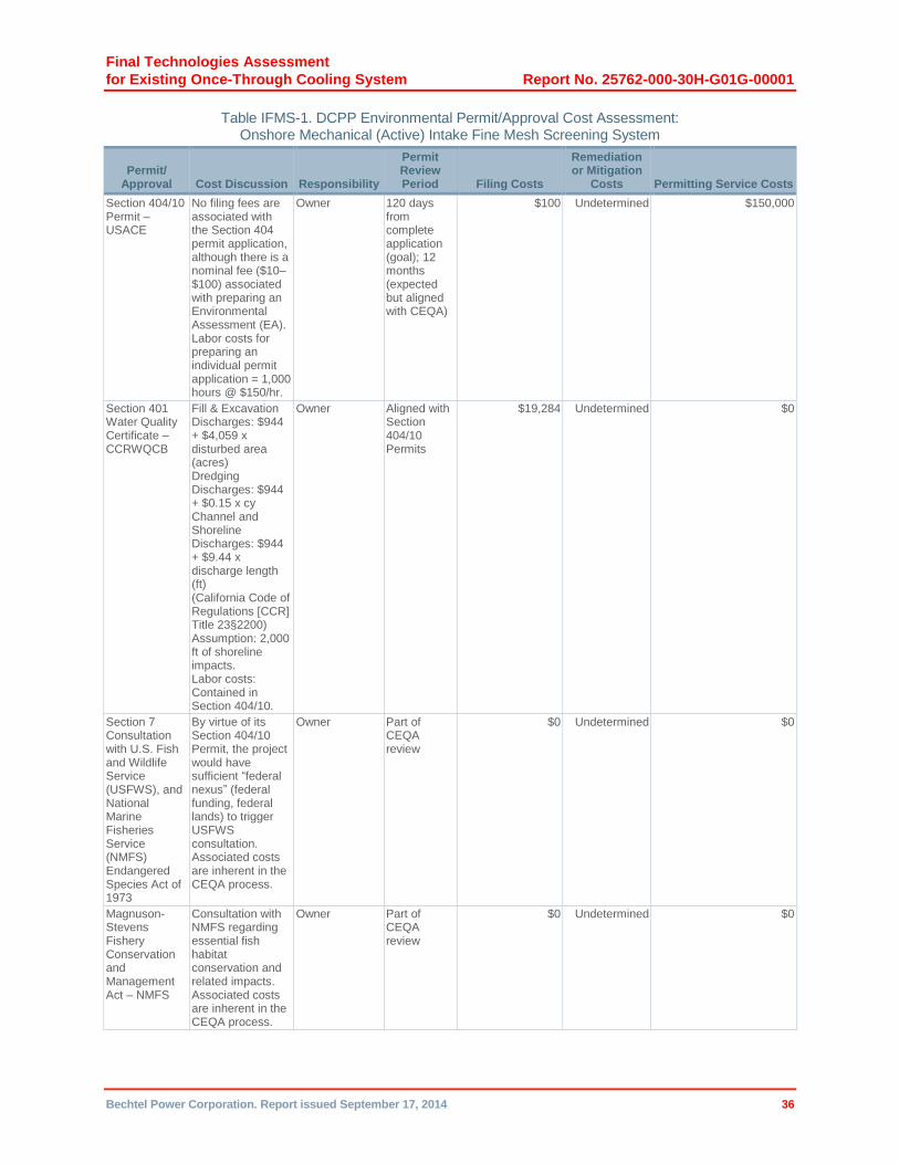
Final Technologies Assessment
for Existing Once-Through Cooling System Report No. 25762-000-30H-G01G-00001
Bechtel Power Corporation. Report issued September 17, 2014 36
Table IFMS-1. DCPP Environmental Permit/Approval Cost Assessment: Onshore Mechanical (Active) Intake Fine Mesh Screening System
Permit/ Approval Cost Discussion Responsibility
Permit Review Period Filing Costs
Remediation or Mitigation
Costs Permitting Service Costs
Section 404/10 Permit – USACE
No filing fees are associated with the Section 404 permit application, although there is a nominal fee ($10–$100) associated with preparing an Environmental Assessment (EA). Labor costs for preparing an individual permit application = 1,000 hours @ $150/hr.
Owner 120 days from complete application (goal); 12 months (expected but aligned with CEQA)
$100 Undetermined $150,000
Section 401 Water Quality Certificate – CCRWQCB
Fill & Excavation Discharges: $944 + $4,059 x disturbed area (acres) Dredging Discharges: $944 + $0.15 x cy Channel and Shoreline Discharges: $944 + $9.44 x discharge length (ft) (California Code of Regulations [CCR] Title 23§2200) Assumption: 2,000 ft of shoreline impacts. Labor costs: Contained in Section 404/10.
Owner Aligned with Section 404/10 Permits
$19,284 Undetermined $0
Section 7 Consultation with U.S. Fish and Wildlife Service (USFWS), and National Marine Fisheries Service (NMFS) Endangered Species Act of 1973
By virtue of its Section 404/10 Permit, the project would have sufficient “federal nexus” (federal funding, federal lands) to trigger USFWS consultation. Associated costs are inherent in the CEQA process.
Owner Part of CEQA review
$0 Undetermined $0
Magnuson-Stevens Fishery Conservation and Management Act – NMFS
Consultation with NMFS regarding essential fish habitat conservation and related impacts. Associated costs are inherent in the CEQA process.
Owner Part of CEQA review
$0 Undetermined $0
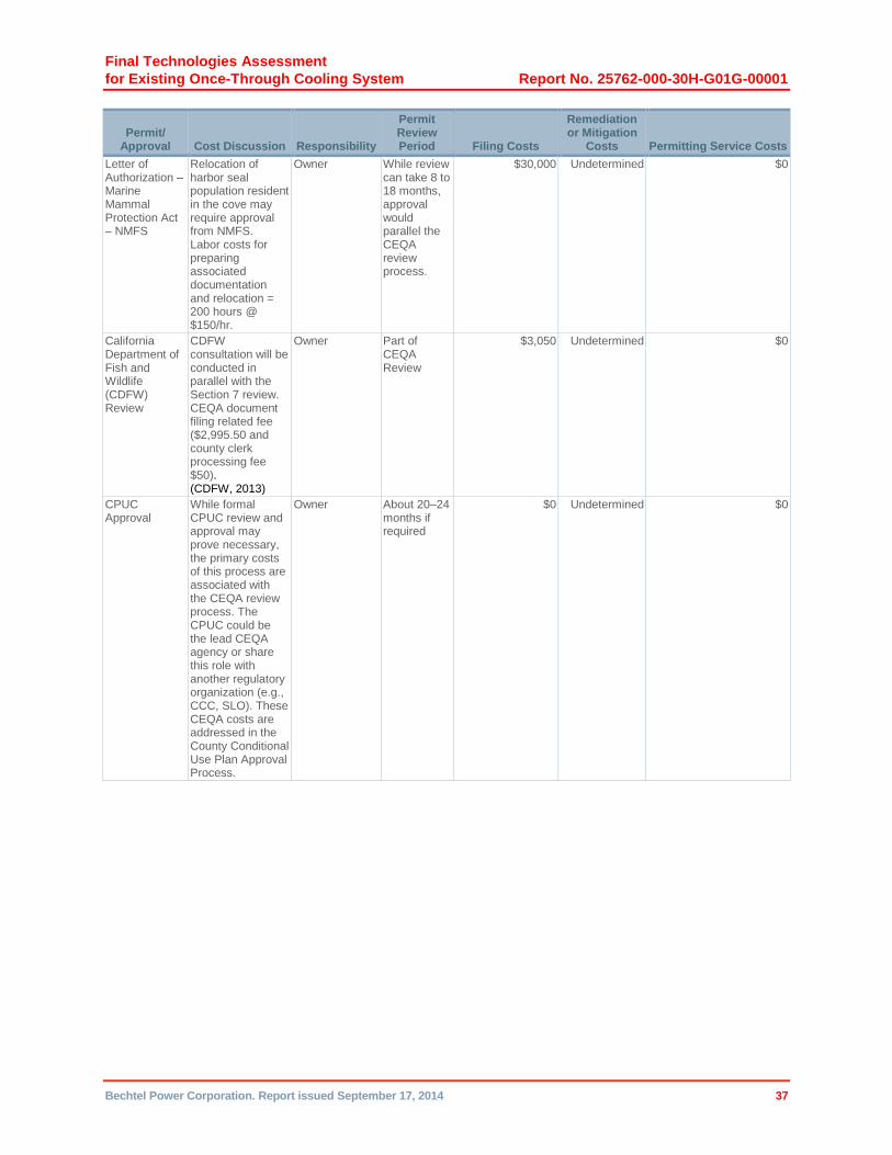
Final Technologies Assessment
for Existing Once-Through Cooling System Report No. 25762-000-30H-G01G-00001
Bechtel Power Corporation. Report issued September 17, 2014 37
Permit/ Approval Cost Discussion Responsibility
Permit Review Period Filing Costs
Remediation or Mitigation
Costs Permitting Service Costs
Letter of Authorization – Marine Mammal Protection Act – NMFS
Relocation of harbor seal population resident in the cove may require approval from NMFS. Labor costs for preparing associated documentation and relocation = 200 hours @ $150/hr.
Owner While review can take 8 to 18 months, approval would parallel the CEQA review process.
$30,000 Undetermined $0
California Department of Fish and Wildlife (CDFW) Review
CDFW consultation will be conducted in parallel with the Section 7 review. CEQA document filing related fee ($2,995.50 and county clerk processing fee $50). (CDFW, 2013)
Owner Part of CEQA Review
$3,050 Undetermined $0
CPUC Approval
While formal CPUC review and approval may prove necessary, the primary costs of this process are associated with the CEQA review process. The CPUC could be the lead CEQA agency or share this role with another regulatory organization (e.g., CCC, SLO). These CEQA costs are addressed in the County Conditional Use Plan Approval Process.
Owner About 20–24 months if required
$0 Undetermined $0

Final Technologies Assessment
for Existing Once-Through Cooling System Report No. 25762-000-30H-G01G-00001
Bechtel Power Corporation. Report issued September 17, 2014 38
Permit/ Approval Cost Discussion Responsibility
Permit Review Period Filing Costs
Remediation or Mitigation
Costs Permitting Service Costs
Coastal Development Permit – CCC/Local Coastal Programs
The CCC indicates that the filing fee for non-residential development is $53,000 (CCC, 2008). There may be additional fees for reimbursement of reasonable expenses, including public notice costs. CEQA costs are covered in the County Condition Use Plan Approval Process. Labor costs for preparing/submitting related forms and documentation = 2,000 hours @ $150/hr.
Owner A 3–9 month process is advertised, but it would be aligned with the CEQA review process
$53,000 Undetermined $300,000
Coastal Development Lease – CSLC and potential CEQA Lead Agency
The Commission lease-related fees include (CSLC, 2011): Industrial Lease: $25,000 Dredge Lease Fee: $1,500 Filing Fee: $25 Labor costs for preparing/submitting related forms and documentation = 3,000 hours @ $150/hr.
Owner Depends on duration of CEQA review process; about 2 years
$26,525 Undetermined $450,000
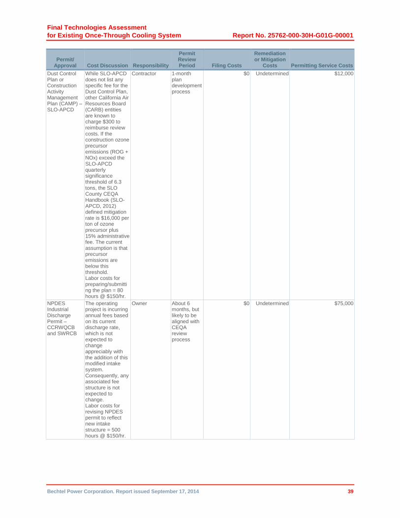
Final Technologies Assessment
for Existing Once-Through Cooling System Report No. 25762-000-30H-G01G-00001
Bechtel Power Corporation. Report issued September 17, 2014 39
Permit/ Approval Cost Discussion Responsibility
Permit Review Period Filing Costs
Remediation or Mitigation
Costs Permitting Service Costs
Dust Control Plan or Construction Activity Management Plan (CAMP) – SLO-APCD
While SLO-APCD does not list any specific fee for the Dust Control Plan, other California Air Resources Board (CARB) entities are known to charge $300 to reimburse review costs. If the construction ozone precursor emissions (ROG + NOx) exceed the SLO-APCD quarterly significance threshold of 6.3 tons, the SLO County CEQA Handbook (SLO-APCD, 2012) defined mitigation rate is $16,000 per ton of ozone precursor plus 15% administrative fee. The current assumption is that precursor emissions are below this threshold. Labor costs for preparing/submitting the plan = 80 hours @ $150/hr.
Contractor 1-month plan development process
$0 Undetermined $12,000
NPDES Industrial Discharge Permit – CCRWQCB and SWRCB
The operating project is incurring annual fees based on its current discharge rate, which is not expected to change appreciably with the addition of this modified intake system. Consequently, any associated fee structure is not expected to change. Labor costs for revising NPDES permit to reflect new intake structure = 500 hours @ $150/hr.
Owner About 6 months, but likely to be aligned with CEQA review process
$0 Undetermined $75,000
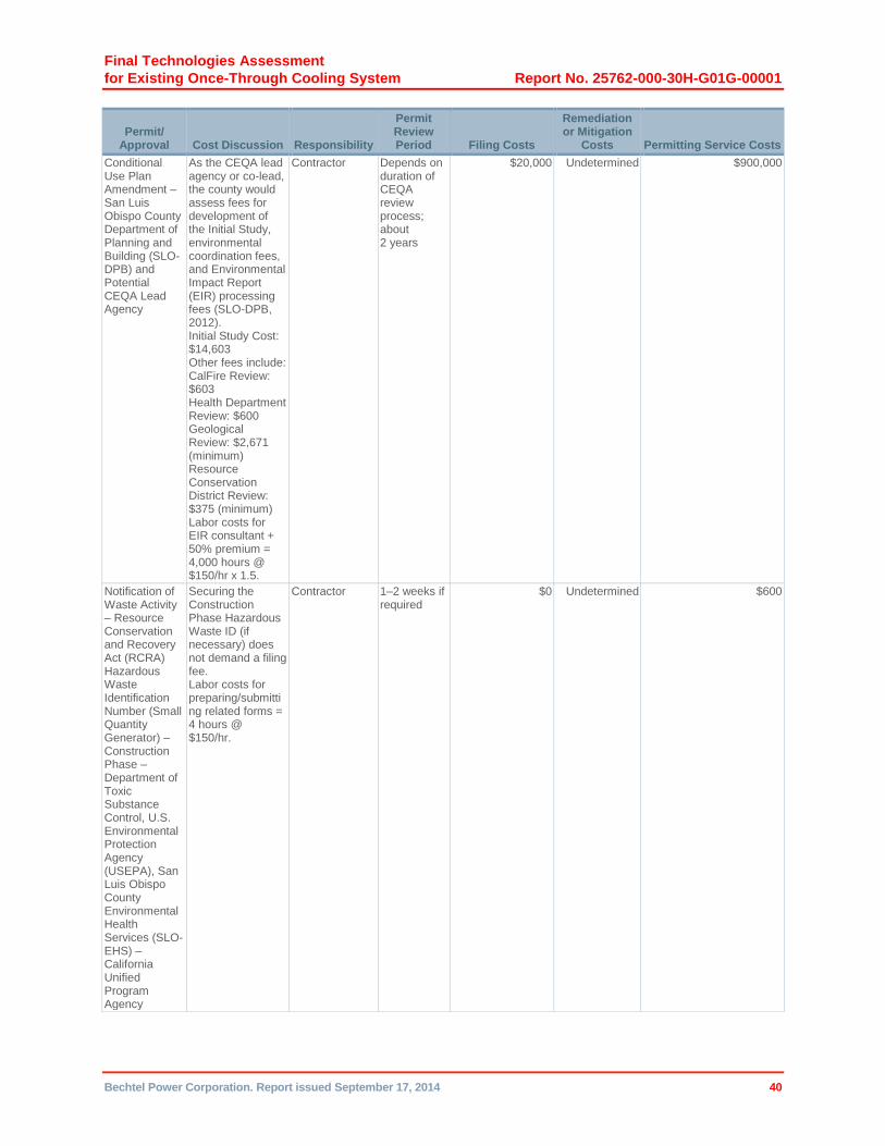
Final Technologies Assessment
for Existing Once-Through Cooling System Report No. 25762-000-30H-G01G-00001
Bechtel Power Corporation. Report issued September 17, 2014 40
Permit/ Approval Cost Discussion Responsibility
Permit Review Period Filing Costs
Remediation or Mitigation
Costs Permitting Service Costs
Conditional Use Plan Amendment – San Luis Obispo County Department of Planning and Building (SLO-DPB) and Potential CEQA Lead Agency
As the CEQA lead agency or co-lead, the county would assess fees for development of the Initial Study, environmental coordination fees, and Environmental Impact Report (EIR) processing fees (SLO-DPB, 2012). Initial Study Cost: $14,603 Other fees include: CalFire Review: $603 Health Department Review: $600 Geological Review: $2,671 (minimum) Resource Conservation District Review: $375 (minimum) Labor costs for EIR consultant + 50% premium = 4,000 hours @ $150/hr x 1.5.
Contractor Depends on duration of CEQA review process; about 2 years
$20,000 Undetermined $900,000
Notification of Waste Activity – Resource Conservation and Recovery Act (RCRA) Hazardous Waste Identification Number (Small Quantity Generator) – Construction Phase – Department of Toxic Substance Control, U.S. Environmental Protection Agency (USEPA), San Luis Obispo County Environmental Health Services (SLO-EHS) – California Unified Program Agency
Securing the Construction Phase Hazardous Waste ID (if necessary) does not demand a filing fee. Labor costs for preparing/submitting related forms = 4 hours @ $150/hr.
Contractor 1–2 weeks if required
$0 Undetermined $600
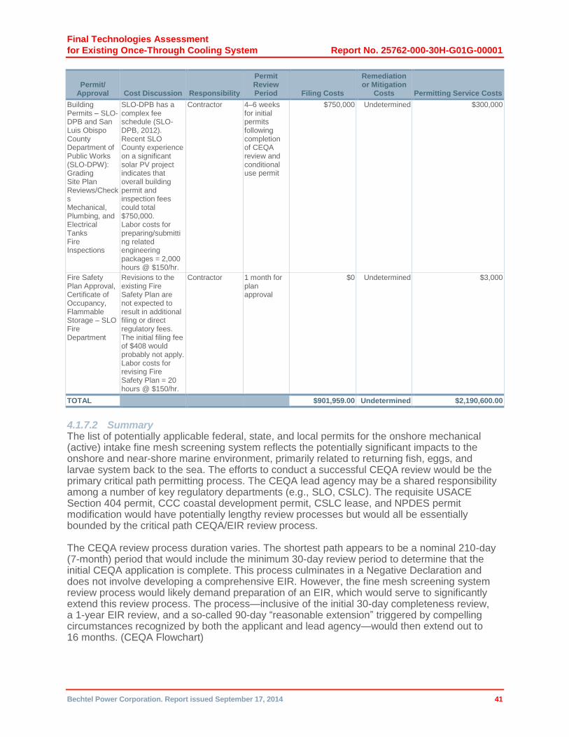
Final Technologies Assessment
for Existing Once-Through Cooling System Report No. 25762-000-30H-G01G-00001
Bechtel Power Corporation. Report issued September 17, 2014 41
Permit/ Approval Cost Discussion Responsibility
Permit Review Period Filing Costs
Remediation or Mitigation
Costs Permitting Service Costs
Building Permits – SLO-DPB and San Luis Obispo County Department of Public Works (SLO-DPW): Grading Site Plan Reviews/Checks Mechanical, Plumbing, and Electrical Tanks Fire Inspections
SLO-DPB has a complex fee schedule (SLO-DPB, 2012). Recent SLO County experience on a significant solar PV project indicates that overall building permit and inspection fees could total $750,000. Labor costs for preparing/submitting related engineering packages = 2,000 hours @ $150/hr.
Contractor 4–6 weeks for initial permits following completion of CEQA review and conditional use permit
$750,000 Undetermined $300,000
Fire Safety Plan Approval, Certificate of Occupancy, Flammable Storage – SLO Fire Department
Revisions to the existing Fire Safety Plan are not expected to result in additional filing or direct regulatory fees. The initial filing fee of $408 would probably not apply. Labor costs for revising Fire Safety Plan = 20 hours @ $150/hr.
Contractor 1 month for plan approval
$0 Undetermined $3,000
TOTAL $901,959.00 Undetermined $2,190,600.00
4.1.7.2 Summary The list of potentially applicable federal, state, and local permits for the onshore mechanical (active) intake fine mesh screening system reflects the potentially significant impacts to the onshore and near-shore marine environment, primarily related to returning fish, eggs, and larvae system back to the sea. The efforts to conduct a successful CEQA review would be the primary critical path permitting process. The CEQA lead agency may be a shared responsibility among a number of key regulatory departments (e.g., SLO, CSLC). The requisite USACE Section 404 permit, CCC coastal development permit, CSLC lease, and NPDES permit modification would have potentially lengthy review processes but would all be essentially bounded by the critical path CEQA/EIR review process.
The CEQA review process duration varies. The shortest path appears to be a nominal 210-day (7-month) period that would include the minimum 30-day review period to determine that the initial CEQA application is complete. This process culminates in a Negative Declaration and does not involve developing a comprehensive EIR. However, the fine mesh screening system review process would likely demand preparation of an EIR, which would serve to significantly extend this review process. The process—inclusive of the initial 30-day completeness review, a 1-year EIR review, and a so-called 90-day “reasonable extension” triggered by compelling circumstances recognized by both the applicant and lead agency—would then extend out to 16 months. (CEQA Flowchart)

Final Technologies Assessment
for Existing Once-Through Cooling System Report No. 25762-000-30H-G01G-00001
Bechtel Power Corporation. Report issued September 17, 2014 42
The CEQA review process would be extended even further by conservatively adding an additional 8 months to cover “unreasonable delays” ostensibly associated with the applicant’s difficulty in supplying requested information. Collectively, this longer and probably more applicable 2-year CEQA review process would likely follow a 1-year period of permit application development. The other permitting processes are assumed to proceed in parallel to the critical path CEQA review process.
The total permit filing and permitting service costs associated with this 3-year permitting process would be approximately $3.0 million. As noted earlier, this 3-year period does not reflect the impact of permit appeals, litigation, or potentially negotiated CEQA-related mitigation fees. In recognition that such complications may occur, the project execution schedule adds a 3-month appeal period following the CEQA final decision.
4.1.7.3 Sources 1. California Coastal Commission (CCC) Permit Application Instructions, Appendix E Filing
Fee Schedule (3/17/2008).
2. California Code of Regulations (CCR) Title 23§2200 Annual Fee Schedules – Subpart a(3) Dredge and Fill Materials.
3. California State Lands Commission (CSLC), Land Management Division Application Guidelines (10/12/2011).
4. California Department of Fish and Wildlife CEQA Document Filing Fees, 2013 http://www.dfg.ca.gov/habcon/ceqa/ceqa_changes.html.
5. California State Water Resources Control Board (SWRCB) Fee Schedule 2012-2013, 2012 http://www.swrcb.ca.gov/resources/fees/docs/fy12_13_fee_schedule_npdes_permit.pdf.
6. California Environmental Quality Act (CEQA) Flowchart for Local Agencies: California Code – Section 21151.5, http://www.ceres.ca.gov/planning/ceqa/flowchart.html.
7. San Luis Obispo County Air Pollution Control District (SLO-APCD) CEQA Air Quality Handbook – A Guide for Assessing the Air Quality Impacts for Projects Subject to CEQA Review, April 2012.
8. San Luis Obispo County Department of Planning and Building (SLO-DPB) – Fee Schedule 2012-2013, 2012.
4.2 Offshore Modular Wedge Wire Screening Technology
The concept selected for installing the offshore modular wedge wire screening technology involves enclosing the existing intake cove to form a shoreline basin and extending a new CW conveyance system, either tunnel or buried piping, from the basin to the ocean. Wedge wire screen assemblies would be attached to the ocean end of this conveyance system to enable it to supply filtered seawater to the newly created intake basin, which would be sealed to prevent direct seawater inflow. (See Process Flow Diagram 25762-110-M6K-WL-00006.)
The offshore location of the wedge wire screens is dependent on local bathymetry and biological sensitivity and the need to provide adequate depth above and below the screens to maintain their hydraulic performance. The open sea oceanographic setting and geological characteristics offshore of DCPP pose significant challenges to this type of conveyance system; consequently, two alternative concepts, tunnel and buried piping, were considered. The final selection would be based on the lowest total installed cost of the system.
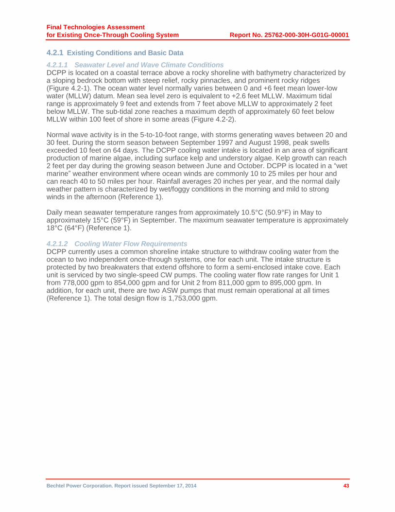
Final Technologies Assessment
for Existing Once-Through Cooling System Report No. 25762-000-30H-G01G-00001
Bechtel Power Corporation. Report issued September 17, 2014 43
4.2.1 Existing Conditions and Basic Data
4.2.1.1 Seawater Level and Wave Climate Conditions DCPP is located on a coastal terrace above a rocky shoreline with bathymetry characterized by a sloping bedrock bottom with steep relief, rocky pinnacles, and prominent rocky ridges (Figure 4.2-1). The ocean water level normally varies between 0 and +6 feet mean lower-low water (MLLW) datum. Mean sea level zero is equivalent to +2.6 feet MLLW. Maximum tidal range is approximately 9 feet and extends from 7 feet above MLLW to approximately 2 feet below MLLW. The sub-tidal zone reaches a maximum depth of approximately 60 feet below MLLW within 100 feet of shore in some areas (Figure 4.2-2).
Normal wave activity is in the 5-to-10-foot range, with storms generating waves between 20 and 30 feet. During the storm season between September 1997 and August 1998, peak swells exceeded 10 feet on 64 days. The DCPP cooling water intake is located in an area of significant production of marine algae, including surface kelp and understory algae. Kelp growth can reach 2 feet per day during the growing season between June and October. DCPP is located in a “wet marine” weather environment where ocean winds are commonly 10 to 25 miles per hour and can reach 40 to 50 miles per hour. Rainfall averages 20 inches per year, and the normal daily weather pattern is characterized by wet/foggy conditions in the morning and mild to strong winds in the afternoon (Reference 1).
Daily mean seawater temperature ranges from approximately 10.5°C (50.9°F) in May to approximately 15°C (59°F) in September. The maximum seawater temperature is approximately 18°C (64°F) (Reference 1).
4.2.1.2 Cooling Water Flow Requirements DCPP currently uses a common shoreline intake structure to withdraw cooling water from the ocean to two independent once-through systems, one for each unit. The intake structure is protected by two breakwaters that extend offshore to form a semi-enclosed intake cove. Each unit is serviced by two single-speed CW pumps. The cooling water flow rate ranges for Unit 1 from 778,000 gpm to 854,000 gpm and for Unit 2 from 811,000 gpm to 895,000 gpm. In addition, for each unit, there are two ASW pumps that must remain operational at all times (Reference 1). The total design flow is 1,753,000 gpm.

Final Technologies Assessment
for Existing Once-Through Cooling System Report No. 25762-000-30H-G01G-00001
Bechtel Power Corporation. Report issued September 17, 2014 44
Figure 4.2-1. DCPP Site Location Map (Contour elevations = feet below MLLW)

Final Technologies Assessment
for Existing Once-Through Cooling System Report No. 25762-000-30H-G01G-00001
Bechtel Power Corporation. Report issued September 17, 2014 45
Figure 4.2-2. DCPP Bathymetry Map (Contour elevations = feet below MLLW)
Final Technologies Assessment
for Existing Once-Through Cooling System Report No. 25762-000-30H-G01G-00001
Bechtel Power Corporation. Report issued September 17, 2014 46
4.2.1.3 Site Geology and Geotechnical Engineering Data Geotechnical information is limited, and hydrographic/bathymetry, seismic, geophysical, and geotechnical subsurface investigations would be performed for final design.
The geomorphic regions in the area of DCPP offshore include the Islay shelf to the north and the Santa Rosa Reef shelf to the south (Reference 2). Both shelves have a rocky near-coast portion and a sediment-covered portion further offshore. As reflected in the contours of the seabed (Figure 4.2-1), the near-coast portion is steeper than the sediment-covered offshore portion.
Lithologically, the seabed offshore of DCPP consists of two exposed formations: (i) the Obispo Formation to the south of the breakwater and (ii) a marine-deposit-covered portion further offshore (Reference 2). The Obispo Formation (Tmo) is a roughly 1,300-foot-thick section of marine volcanic deposits and is exposed from the DCPP breakwater to the Shoreline fault. Regional lithology within the Obispo Formation varies considerably, but along the DCPP coastline, three subunits are recognized: (i) resistant tuff (Tmor), (ii) fine-grained sandstone and claystone (Tmof), and (iii) intrusive diabase bedrock (Tmod). The resistant tuff subunit (Tmor) is exposed along the coastline from the base of Green Peak to the south headland of Discharge Cove and is structurally repeated at the north headland of Discharge Cove. The fine-grained sandstone and claystone subunit (Tmof) is exposed along the coastline from the south headland of Discharge Cove to south of Crowbar Hill and is probably structurally repeated north of Crowbar Hill. This fine-grained subunit is more than 330 feet thick and consists of regularly bedded sandstone with minor shale and mudstone that coarsens gradually up-section.
The diabase bedrock subunit (Tmod) has intruded into the resistant tuff subunit along approximately 3,000 feet of coastline south of DCPP. This dike/sill complex is also mapped in the intertidal zone directly south of the breakwater at Intake Cove. The offshore marine deposits (Qs) consist of sand and silty sand with minor gravel deposits that become finer grained progressively offshore. Thin dune-like sand sheets (Qsw) cover parts of the sea floor beyond the Shoreline fault. These are well-defined, low, less-than-3-feet-high, dune-like features with long wave lengths, approximately 82 to 410 feet. There is evidence of their mobile, ephemeral nature. At the base of the marine sand and silt, a gravel-cobble lag is inferred to overlie the top of the bedrock. In summary, the DCPP offshore consists of diabase bedrock exposed near the existing breakwaters and covered with thin sediment further offshore. There is no available information regarding the state of weathering and strength (rippability) of the offshore diabase. If it is considered not feasible to excavate trenches in offshore rock by conventional methods, then removing rock by low-charge blasting can be the alternative. In that case, the impact of blasting on the aquatic life, the power plant, and the nearby faults should be assessed. Effects can be minimized by using multiple small charges. The same considerations apply to the tunnel or piping system that would convey water from the assemblies to the shoreline basin.
4.2.1.4 Site Seismicity From the available information, there is indication for presence of the Shoreline fault located about 1,800 feet offshore of the DCPP. The fault is estimated to be 600 feet offshore of the DCPP inner breakwater, and for both concepts (tunnel and piping systems) the footprint of the wedge wire assembly area is very close to the Shoreline fault, if not overlapping. Based on several qualitative and indirect quantitative estimates of slip rate (the fault zone lies entirely offshore and there are no identified geomorphic features that can be reliably used as lateral offset markers), the interpreted slip rate on the Shoreline fault zone ranges from 0.02 inch/year (0.05 mm/yr) to possibly 0.04 inch/year (1 mm/yr), with a preferred range of 0.008 to 0.012 inch/year (0.2 to 0.3 mm/yr). The slip rate could also be zero (Reference 2). Thus, for both concepts (tunnel and piping), the systems/structures should be designed to withstand the ground motions from this fault and any impact of a potential slip. The extent of the fracture zone
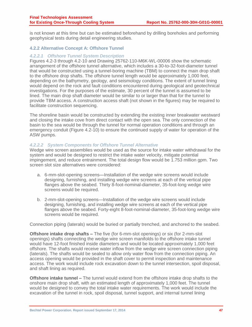
Final Technologies Assessment
for Existing Once-Through Cooling System Report No. 25762-000-30H-G01G-00001
Bechtel Power Corporation. Report issued September 17, 2014 47
is not known at this time but can be estimated beforehand by drilling boreholes and performing geophysical tests during detail engineering studies.
4.2.2 Alternative Concept A: Offshore Tunnel
4.2.2.1 Offshore Tunnel System Description Figures 4.2-3 through 4.2-10 and Drawing 25762-110-M6K-WL-00006 show the schematic arrangement of the offshore tunnel alternative, which includes a 30-to-32-foot-diameter tunnel that would be constructed using a tunnel-boring machine (TBM) to connect the main drop shaft to the offshore drop shafts. The offshore tunnel length would be approximately 1,000 feet, depending on the bathymetry, geology, and seismology conditions. The extent of tunnel lining would depend on the rock and fault conditions encountered during geological and geotechnical investigations. For the purposes of the estimate, 30 percent of the tunnel is assumed to be lined. The main drop shaft diameter would be similar to or larger than that for the tunnel to provide TBM access. A construction access shaft (not shown in the figures) may be required to facilitate construction sequencing.
The shoreline basin would be constructed by extending the existing inner breakwater westward and closing the intake cove from direct contact with the open sea. The only connection of the basin to the sea would be through the tunnel for normal operation conditions and through an emergency conduit (Figure 4.2-10) to ensure the continued supply of water for operation of the ASW pumps.
4.2.2.2 System Components for Offshore Tunnel Alternative Wedge wire screen assemblies would be used as the source for intake water withdrawal for the system and would be designed to restrict the intake water velocity, mitigate potential impingement, and reduce entrainment. The total design flow would be 1.753 million gpm. Two screen slot size alternatives were considered:
a. 6-mm-slot-opening screens—Installation of the wedge wire screens would include designing, furnishing, and installing wedge wire screens at each of the vertical pipe flanges above the seabed. Thirty 8-foot-nominal-diameter, 35-foot-long wedge wire screens would be required.
b. 2-mm-slot-opening screens—Installation of the wedge wire screens would include designing, furnishing, and installing wedge wire screens at each of the vertical pipe flanges above the seabed. Forty-eight 8-foot-nominal-diameter, 35-foot-long wedge wire screens would be required.
Connection piping (laterals) would be buried or partially trenched, and anchored to the seabed.
Offshore intake drop shafts – The five (for 6-mm-slot openings) or six (for 2-mm-slot openings) shafts connecting the wedge wire screen manifolds to the offshore intake tunnel would have 12-foot finished inside diameters and would be located approximately 1,000 feet offshore. The shafts would receive water inflow from the wedge wire screen connection piping (laterals). The shafts would be sealed to allow only water flow from the connection piping. An access opening would be provided in the shaft cover to permit inspection and maintenance access. The work would include rock excavation down to the tunnel intersection, spoil disposal, and shaft lining as required.
Offshore intake tunnel – The tunnel would extend from the offshore intake drop shafts to the onshore main drop shaft, with an estimated length of approximately 1,000 feet. The tunnel would be designed to convey the total intake water requirements. The work would include the excavation of the tunnel in rock, spoil disposal, tunnel support, and internal tunnel lining

Final Technologies Assessment
for Existing Once-Through Cooling System Report No. 25762-000-30H-G01G-00001
Bechtel Power Corporation. Report issued September 17, 2014 48
(grouting and reinforcement of walls) as required (for budgetary price, 30 percent of tunnel length was assumed to be lined).
Onshore main drop shaft – This shaft would be constructed in the existing shoreline basin (intake cove) and intersect with the offshore intake tunnel. The shaft would be sized to accommodate DCPP water flow requirements. The design, fabrication, and installation of screens and debris protection at the top of the shaft would also be provided. The work would include rock excavation down to the tunnel intersection, spoil disposal, and shaft lining as required.
Breakwater – An enclosed shoreline basin would be constructed by extending the east portion of the existing breakwater. The design and materials of the breakwater extension would be similar to those of the existing restored breakwater.
The existing and new breakwaters would be sealed to prevent entry of fish, eggs, and larvae. Engineering evaluations would be made to provide assurance that such measure would not undermine the stability of the breakwater during wave attacks, since pervious breakwaters reduce the magnitude of the impact force.
Emergency backup water supply – Precast reinforced concrete box culverts, including vertical concrete walls and stop logs, would be designed and installed within the new portion of the breakwater. Their design would facilitate stop log installation and removal. The conceptual sketch of this structure is shown in Figure 4.2-10.
It would be necessary to stockpile excavated/dredged tunnel, shaft, and lateral-placement material either on the DCPP site or within a maximum of 5 miles offsite. An access road to the existing east breakwater would also need to be constructed. Dredging activities should have minimal impact on the aquatic life.
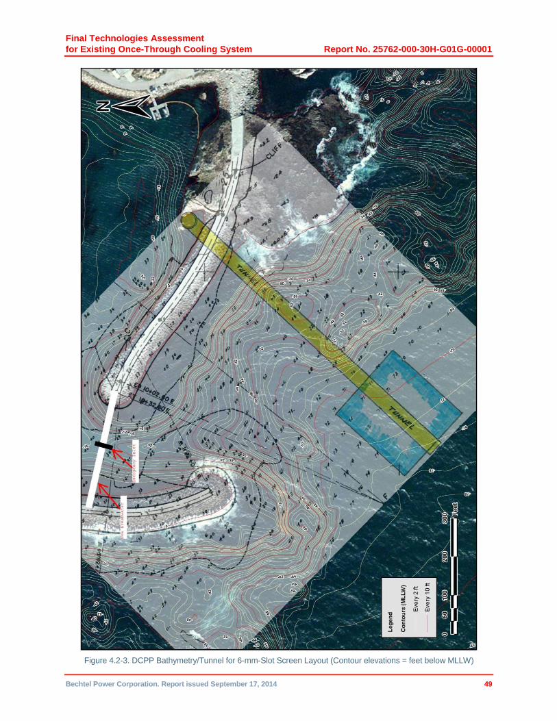
Final Technologies Assessment
for Existing Once-Through Cooling System Report No. 25762-000-30H-G01G-00001
Bechtel Power Corporation. Report issued September 17, 2014 49
Figure 4.2-3. DCPP Bathymetry/Tunnel for 6-mm-Slot Screen Layout (Contour elevations = feet below MLLW)
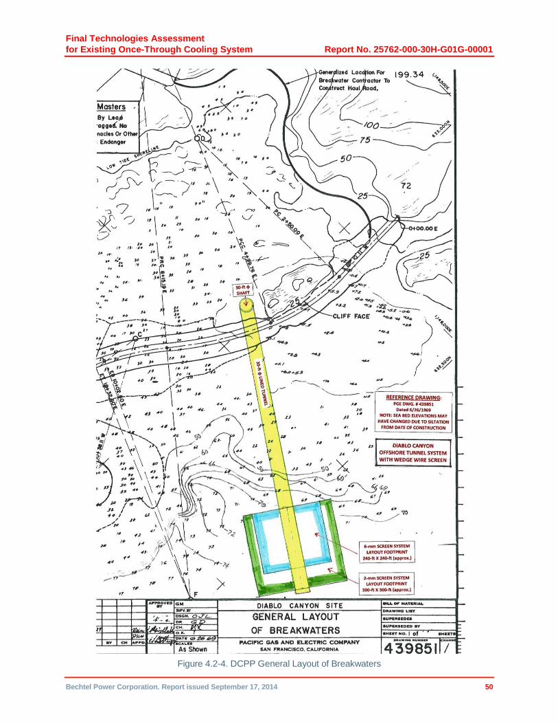
Final Technologies Assessment
for Existing Once-Through Cooling System Report No. 25762-000-30H-G01G-00001
Bechtel Power Corporation. Report issued September 17, 2014 50
Figure 4.2-4. DCPP General Layout of Breakwaters
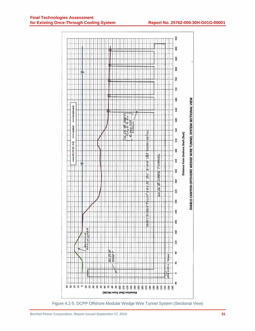
Final Technologies Assessment
for Existing Once-Through Cooling System Report No. 25762-000-30H-G01G-00001
Bechtel Power Corporation. Report issued September 17, 2014 51
Figure 4.2-5. DCPP Offshore Modular Wedge Wire Tunnel System (Sectional View)
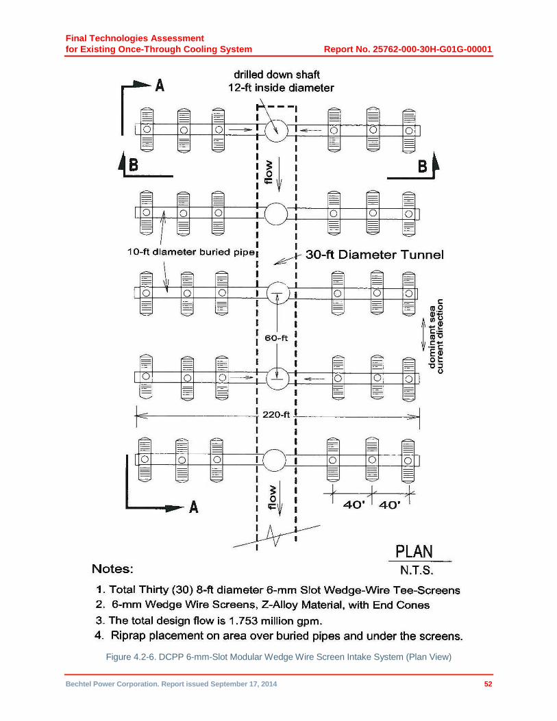
Final Technologies Assessment
for Existing Once-Through Cooling System Report No. 25762-000-30H-G01G-00001
Bechtel Power Corporation. Report issued September 17, 2014 52
Figure 4.2-6. DCPP 6-mm-Slot Modular Wedge Wire Screen Intake System (Plan View)
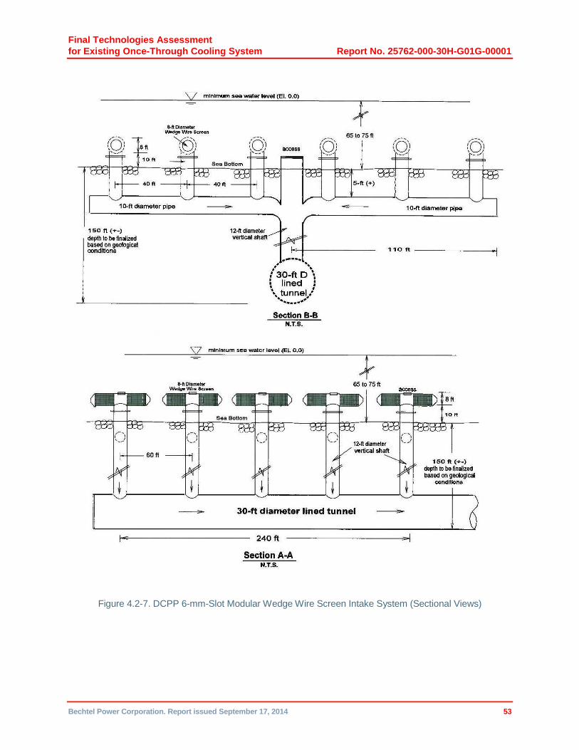
Final Technologies Assessment
for Existing Once-Through Cooling System Report No. 25762-000-30H-G01G-00001
Bechtel Power Corporation. Report issued September 17, 2014 53
Figure 4.2-7. DCPP 6-mm-Slot Modular Wedge Wire Screen Intake System (Sectional Views)

Final Technologies Assessment
for Existing Once-Through Cooling System Report No. 25762-000-30H-G01G-00001
Bechtel Power Corporation. Report issued September 17, 2014 54
Figure 4.2-8. DCPP 2-mm-Slot Modular Wedge Wire Screen Intake System (Plan View)

Final Technologies Assessment
for Existing Once-Through Cooling System Report No. 25762-000-30H-G01G-00001
Bechtel Power Corporation. Report issued September 17, 2014 55
Figure 4.2-9. DCPP 2-mm-Slot Modular Wedge Wire Screen Intake System (Sectional Views)

Final Technologies Assessment
for Existing Once-Through Cooling System Report No. 25762-000-30H-G01G-00001
Bechtel Power Corporation. Report issued September 17, 2014 56
Figure 4.2-10. DCPP Emergency Cooling Water Intake Structure Details