final technologies assessment for existing once...
TRANSCRIPT

Final Technologies Assessment for Existing Once-Through Cooling System Report No. 25762-000-30R-G01G-00010
Bechtel Power Corporation. Report issued September 20, 2013 12
Figure 1-4. Plant Site Rendering

Final Technologies Assessment for Existing Once-Through Cooling System Report No. 25762-000-30R-G01G-00010
Bechtel Power Corporation. Report issued September 20, 2013 88
4.3.1.3.2 New 500 kV Line Tap To energize the required equipment for the proposed cooling towers, four new 500 kV circuits would be brought in from a new expansion on the west side of the existing 500 kV substation (see Figure 4.3-8). Four circuits would leave the substation on the north side and traverse the site on single-circuit monopole dead-end structures. This work would be sequenced at the end of the earthwork operations because cooling tower earthwork must be completed prior to structure erection and stringing. The structures immediately outside the 500 kV substations are proposed to be 150 feet tall; this height provides clearance over the rerouted 230 kV lines. All other 500 kV tap structures are assumed to be 110-foot-tall monopoles. Foundations are currently proposed as caissons because these are usually quick to install using an excavator-mounted Lo-Drill.
Figure 4.3-8. 500 kV Power Supply to the Cooling Towers
It is anticipated that construction would follow a sequence similar to the following:
Perform grading in areas to which the existing lines would be relocated (existing lines still energized)
Place foundations in the newly graded areas (existing lines still energized)
Erect structures
o 230 kV structures - erect lattice towers (existing lines still energized)
o 500 kV structures – erect steel monopoles (existing lines de-energized due to proximity of construction)
String conductor between dead-end towers (lines de-energized)
After connections have been completed and checked off, re-energize lines

Final Technologies Assessment for Existing Once-Through Cooling System Report No. 25762-000-30R-G01G-00010
Bechtel Power Corporation. Report issued September 20, 2013 172
7.3 Estimate Summary
The estimates for all technologies are summarized in Table 7.3-1.
Table 7.3-1. Technology Estimate Summary Technology Project Cost
($ x 1,000,000) PG&E Costs
($ x 1,000,000) Grand Total1
($ x 1,000,000)
Mechanical (Forced) Draft Dry/Air Cooling 2
7,026 – 10,960 1,493 8,519 - 12,453
Passive Draft Dry/Air Cooling 3
7,038 – 10,979 1,374 8,412 – 12,353
Wet Mechanical (Forced) Draft Cooling
5,501 – 8,581 1,374 6,875 – 9,955
Wet Natural Draft Cooling
7,011 – 10,938 1,493 8,504 – 12,431
Hybrid Wet/Dry Cooling 5,480 – 8,549 1,374 6,854 – 9,923
Onshore Mechanical Fine Mesh Screening
164 - 256 237 371 - 493
Offshore Modular Wedge Wire Screening System
261 - 407 0 261 - 407
7.3.1 Estimate Summary Explained
The estimate summary is explained in the Table 7.3.1-1.
The estimate summaries for each technology are provided below:
DCPP Once Through Cooling System
TECHNOLOGY OPTION
Estimate Summary
Description Comments Civil Typical items included are material, labor and
subcontract costs for mountain excavation, foundation excavation and back fill, concrete, structural steel and architectural as applicable.
Mechanical Typical items included are material, labor and subcontract costs for cooling towers, rotating equipment, steam generator blade replacements, condenser upgrades, water treatment, tanks and other mechanical equipment as applicable
1 All technology estimates include PG&E provided cost for USNRC review of environmental impact statements 2, 3 Includes PG&E-provided steam turbine replacement costs.

Final Technologies Assessment for Existing Once-Through Cooling System Report No. 25762-000-30R-G01G-00010
Bechtel Power Corporation. Report issued September 20, 2013 173
Piping Typical items included are material, labor and subcontract costs for piping systems associated with recycle water pipe line, service and fire water systems as applicable.
Electrical and Instrumentation Controls Typical items included are material, labor and subcontract costs associated with instrumentation, electrical equipment, transmission lines, switch yard and electrical bulks as applicable
Traffic and Logistics Includes freight costs for materials. TOTAL DIRECT COST Other Field Costs (Field Non-Manual, Craft Distributables)
Typical Items included are field craft indirect labor (such as Temporary construction, housekeeping, tool room management, etc.) and materials (such as small tools, consumables, construction equipment, cranes, craft break trailer, office trailers, etc.), field non-manual labor (such as craft supervision, field engineering, safety, quality, field project controls, etc.) and their other direct costs such as (computers, internet, office supplies, business travel, relocation and living costs, etc.).
Engineering Services Includes engineering and other home office services costs
TOTAL CONSTRUCTED COST Other Costs (Securities, Insurances, Taxes Warranties and Permits)
Insurances, Securities, Sales Taxes, Construction Permits, etc.
TOTAL COST Contingency is expected in range Appropriate contingency for unknowns TOTAL PROJECT COST Fee Contractor fee TOTAL PROJECT PRICE
Final Technologies Assessment for Existing Once-Through Cooling System Report No. 25762-000-30R-G01G-00010
Bechtel Power Corporation. Report issued September 20, 2013 174
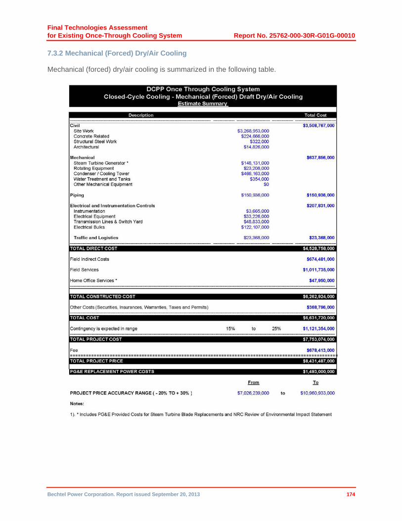
7.3.2 Mechanical (Forced) Dry/Air Cooling
Mechanical (forced) dry/air cooling is summarized in the following table.

Final Technologies Assessment for Existing Once-Through Cooling System Report No. 25762-000-30R-G01G-00010
Bechtel Power Corporation. Report issued September 20, 2013 175
7.3.3 Passive Draft Dry/Air Cooling
Passive draft dry/air cooling is summarized in the following table.

Final Technologies Assessment for Existing Once-Through Cooling System Report No. 25762-000-30R-G01G-00010
Bechtel Power Corporation. Report issued September 20, 2013 176
7.3.4 Wet Mechanical (Forced) Draft Cooling
Wet mechanical (forced) draft cooling is summarized in the following table.

Final Technologies Assessment for Existing Once-Through Cooling System Report No. 25762-000-30R-G01G-00010
Bechtel Power Corporation. Report issued September 20, 2013 177
7.3.5 Wet Natural Draft Cooling
Wet natural draft cooling is summarized in the following table.

Final Technologies Assessment for Existing Once-Through Cooling System Report No. 25762-000-30R-G01G-00010
Bechtel Power Corporation. Report issued September 20, 2013 178
7.3.6 Hybrid Wet/Dry Cooling
Hybrid wet/dry cooling is summarized in the following table.

Final Technologies Assessment for Existing Once-Through Cooling System Report No. 25762-000-30R-G01G-00010
Bechtel Power Corporation. Report issued September 20, 2013 179
7.3.7 Onshore Mechanical (Active) Fine Mesh Screening
Onshore mechanical (active) fine mesh screening is summarized in the following table.

Final Technologies Assessment for Existing Once-Through Cooling System Report No. 25762-000-30R-G01G-00010
Bechtel Power Corporation. Report issued September 20, 2013 180
7.3.8 Offshore Modular Wedge Wire Screening
Offshore modular wedge wire screening is summarized in the following table.

Final Technologies Assessment for Existing Once-Through Cooling System Report No. 25762-000-30R-G01G-00010
Bechtel Power Corporation. Report issued September 20, 2013 181
The details used to develop estimates above are explained in the following sections.
7.4 Quantity Development
Engineering prepared the scope of work documents and quantity takeoffs in support of a Class 3 estimate and provided those documents to the Estimating department for each closed-cycle cooling technology and the onshore mechanical fine mesh screening technology separately. Estimating prepared an estimate for the technologies based on the following:
Item Comments
Plant Layout/General Arrangement
Preliminary plot plans based on equipment layouts from vendors
Site Work Preliminary based on volume of mountain excavation, CW duct excavation, underground pipeline excavations, and foundation excavations
Concrete Preliminary foundation designs
Steel Preliminary steel designs
Mechanical Equipment Equipment lists
Concrete CW Ducts Preliminary layout drawings
Piping Based on preliminary piping and instrumentation diagrams (P&IDs) and layout drawings
Electrical Equipment Preliminary single-line diagrams
Electrical Bulks Based on preliminary layout and equipment location
Instruments and Controls Based on Preliminary P&I Schematics
For the offshore modular wedge wire screening option, Engineering prepared a performance specification with all the necessary drawings and documents to solicit budgetary quotes for a complete marine works package. Estimating validated the quotes received for the marine works package based on clarification meeting with the selected vendor and in house data. Estimating prepared quantity takeoffs from drawings in the performance specification and estimated costs for extending and sealing the existing breakwater on a direct-hire union construction basis. The selected vendor quote and estimate for extending and sealing the existing breakwater form the basis of the offshore modular wedge wire screening estimate.
The following sections provide quantity summaries for each technology.

Final Technologies Assessment for Existing Once-Through Cooling System Report No. 25762-000-30R-G01G-00010
Bechtel Power Corporation. Report issued September 20, 2013 149
5.3 Closed-Cycle Cooling, Passive Draft Dry Air; Mechanical Draft Dry Air; Wet Natural Draft; Wet Mechanical Draft; and Hybrid Wet/Dry Cooling
The major construction work components of the closed-cycle cooling technologies are:
� Relocation of the 230 kV offsite power feed
� Expansion of the 500 kV switchyard and installation of six additional breakers
� Subsurface investigation and excavation for the cooling tower footprint
� Erection of the cooling towers
� Installation of CW pipe and duct to the new pumphouses
� Installation of four new transformers near the cooling towers
� Building and powering of the two new pumphouses with four pumps each; switchgear and ductbank
� Demolition of five existing buildings within the CW duct excavation footprint and rebuilding of buildings 102, 519, and 527 outside the footprint
� Installation of the underground piping and valves, concrete duct work
� Demolition and relocation of underground interferences west of the turbine buildings
� Demolition of the existing CW ducts and decommissioning of existing intake pumps and abandonment of the power feed from the plant
� Demolition of the low pressure condenser interiors and retubing with new tube sheets in each unit
� Rebuilding of the low pressure turbines in each unit
For the wet cooling technology options only, the following are additional construction work components:
� Addition of a desalination plant
� Addition of a water treatment plant, recycle water tank, and fresh water storage pond
� Installation of pipelines and pumping stations from the San Luis Obispo and Morro Bay wastewater treatment facilities to the plant site new water treatment facility
� Installation of a new service cooling water and condensate cooler heat exchangers
For the dry cooling technology options only, the following are additional construction work components:
� New saltwater cooling system pumps and piping from the intake structure to the new plant service water cooling heat exchangers and condensate coolers.

Final Technologies Assessment for Existing Once-Through Cooling System Report No. 25762-000-30R-G01G-00010
Bechtel Power Corporation. Report issued September 20, 2013 150
For the mechanical draft wet and dry technology options only, the following is an additional construction work component:
� Powering the mechanical draft fans
The construction approach for the closed cooling system options are all very similar in that the cooling tower grade elevation for the five different technologies is set at elevation 115’ and is located north of the plant. All cooling tower layout location footprints avoid the Indian burial grounds.
The 12-foot-diameter CW pipe routing from the cooling towers across the Diablo Creek to the new pumphouses are all very similar for each option. The construction of the new pumphouses for each unit, the power and control routing, and the concrete conduit duct from the turbine buildings to the pumphouses are the same for all options, as well as the demolition of the existing buildings, excavation, interference removal, and demolition of the current CW system ducting west of the turbine buildings. The rebuilding of the condensers and low pressure turbines for each option is the same.
The sequence of the construction activities and installations for each of the closed-cycle cooling options is shown on the individual Level 2 schedules.
5.3.1 230 kV Power Transmission Line Rerouting To accommodate the mountain excavation activities, the first construction activity would be relocated about a mile of the existing 230 kV offsite power transmission line from Morro Bay-Mesa Line, which would be rerouted outside the excavation footprint to the east. This would entail the installation of new foundations and transmission towers further east, restringing new two-conductor three-phase cable and grounding/communications wire, and scheduling a minor outage to perform the de-terminations of the existing lines and re-termination of the new lines. Removal of the existing transmission towers and installation of temporary barriers to protect the existing switchyard area during excavation would follow.
5.3.2 500 kV Switchyard Expansion To power the closed cooling options, the expansion of the existing 500 kV switchyard would be necessary, which would entail installation of six additional breakers (two bays). The area west of the existing 500 kV switchyard would be graded to the same elevation and new breakers would be installed and interconnected to the new transformers via monopole towers to feed the new transformers near the cooling towers.
5.3.3 Excavation Activities Of the five options, there are two different footprints to accommodate the number of cooling towers in each tower array. The wet mechanical and hybrid technologies have two tower (one per unit) arrays, while the dry mechanical, dry natural, and wet natural technologies have four tower (two per unit) arrays, which drive the excavation quantities required for each of the two footprints. The flat platform area for the two cooling towers is approximately 62 acres, and the flat platform area for the four cooling towers is approximately 109 acres.
The excavation quantity required to accommodate the two-tower footprint is approximately 190 million cubic yards, while the four-tower footprint requires approximately 316 million cubic yards of excavation. Excavation work would be very similar to the excavation performed for the new Qinshan Nuclear Units 2 and 3, which is located next to the operating Unit 1 in a mountainous area on the East China Sea south of Shanghai, China. The construction approach would be to use drilling and shooting, large shovel excavators (22 cubic yard buckets) and large off-road

Final Technologies Assessment for Existing Once-Through Cooling System Report No. 25762-000-30R-G01G-00010
Bechtel Power Corporation. Report issued September 20, 2013 151
trucks (100-ton payload) to haul excavated material approximately 5 miles away to the spoils areas. Two potential spoils areas have been identified that could hold the largest quantity of excavated material (see Drawings 25762-110-CEK-7200-00001, 00002, 00003, 00004, and 00005). The 264-acre spoils area that has a current low point at approximately elevation 600’ could be filled to an approximate elevation of 1,000 to 1,200’ (400’ to 600’) depth. The second 46-acre spoils area starts at approximately elevation 680’ and could be filled to an approximate elevation of 1,000’ (320’ depth).
The excavation duration for the two-tower configuration would be approximately 25 months, and the four-tower duration would be approximately 41 months, with about 3 months’ mobilization time. The mobilization will facilitate environmental controls, stormwater management, erosion control, fugitive dust controls, equipment assembly, and infrastructure facilities setup.
With regard to the excavation of rock for the cooling tower footprints, a stepped configuration (50-foot vertical and 100-foot horizontal steps from elevation 115’ [grade] up to elevation 900’ or 1,100’) as shown on Drawings 25762-110-CEK-7200-00001, 00002, 00003, 00004, and 00005 assumes that the excavated material is strong, sound rock with minimal fractures and horizontal bedding. If the rock is fractured or jointed, or has bedding planes that slope into the excavation, then additional measures will have to be taken (such as rock bolts) to ensure excavation stability (these measures have not been included in the estimate). Geotechnical borings and subsurface investigations would be made prior to the final detailed design of the excavation, and environmental impact studies would be conducted to facilitate the permitting process.
Subsurface areas would be excavated for foundations, pumphouses, duct, and pipe during a nonoutage period, while the existing circulating system, diesel fuel storage tanks, and the balance of duct and pipe installations west of the turbine buildings would be demolished during a dual unit outage period.
5.3.4 Circulating Water Piping and Duct Excavation The eight 12-foot-diameter FRP CW pipes from the cooling tower array would be routed to the new Unit 1 pumphouse area and cross Diablo Creek, requiring an approximately 150-foot-wide and 25-foot deep excavation and the existing Diablo Creek buried duct to be extended east of the excavation footprint.
The piping would be installed in 40-foot lengths on a bed of sand with laminated restrained wrapped ridged joints without thrust blocks (see Section A_A on Drawings 25762-110-P1K-WL-00010, 00020, 00030, 00040 and 00050).
A 344,000 cubic yard excavation from the new Unit 1 pumphouse area to the new Unit 2 pumphouse and to the turbine buildings is required to facilitate the installation of 40,000 cubic yards of poured-in-place reinforced concrete duct. The area north of the Unit 1 turbine excavated during nonoutage periods. The area to the west of the turbine buildings would be excavated during the outage period. The two belowground, 50,000-gallon emergency diesel fuel oil storage tanks would be removed. The existing concrete CW intake and discharge ducts (12,514 cubic yards) would be demolished and removed as part of the excavation during the dual-unit plant outage period. Drawing 25762-P1K-WL-00013 illustrates the area of demolition. The eight existing CW duct ends (intake and discharge) outside the excavation would be sealed with concrete closures and abandoned in place.
An excavation for the new saltwater cooling lines for the dry cooling tower options would be routed from the intake structure parallel to the existing 1-1 conduit to the new excavation west of the Units 1 and 2 turbine buildings (see Drawings 25762-P1K-WL-00011 and 12), and then to the plant service cooling water heat exchangers and condensate coolers.

Final Technologies Assessment for Existing Once-Through Cooling System Report No. 25762-000-30R-G01G-00010
Bechtel Power Corporation. Report issued September 20, 2013 97
4.3.4 Wet Cooling Technologies—Overview
4.3.4.1 Mechanical Design The primary differences between wet cooling towers and dry cooling towers are that a wet cooling tower consumes water due to evaporation, drift, and blowdown and achieves lower cold water temperatures because of the difference between wet and dry bulb temperatures. Currently, DCPP does not have the resources to produce water of adequate quality needed for the proposed cooling towers. Therefore, water required for the towers would be obtained from a new onsite desalination plant and from processed reclaimed water obtained from the surrounding communities. A water balance was performed for the wet cooling tower variants to determine the quantity of water required (refer to Water Balance 2562-110-M5K-YA-00001). The towers for each unit would consume approximately 16,550 gpm.
It should be noted that the State Water Board is currently developing amendments to the Water Quality Control Plan for Ocean Waters of California. The amended Plan, once adopted, may include requirements for intake and/or brine discharges that could result in restrictions or additional requirements on the use of desalination at the site.
Currently, up to 2,800 gpm of reclaimed water can be obtained from the following wastewater treatment plants, both within a 20-mile radius of DCPP:
San Luis Obispo
Morro Bay/Cayucos
Because this quantity is insufficient to support DCPP operation, a supplementary desalinization plant has been included, designed to supply 100 percent of the required makeup water. Refer to Figure 4.3-13 for proposed reclaim water routing.
The desalination facility would be located north of the turbine building and north of the SLO-2 archeological site. Three desalination seawater supply pumps would be installed in the existing plant shoreline intake structure. Piping would be routed from the intake structure around the SLO-2 archeological site to the desalination facility (refer to General Arrangement Drawing 25762-110-P1K-WL-00032). The new proposed seawater supply piping would be routed entirely below grade except in the screen house, where it would be within the building. No piping would be exposed as it crosses the protected area. A second line would be routed from the desalination facility to discharge the brine produced by the desalination process back to near the CW discharge (refer to General Arrangement Drawing 25762-110-P1K-WL-00030) and further extended offshore to a sufficient depth and non-stagnant ambient location. A multiport diffuser would be fitted at the end of the effluent discharge to achieve the dilution needed to comply with state discharge requirements. The offshore discharge pipe would be buried and protected against current- and wave-induced erosive forces. The water produced by the desalination facility would be pumped to an approximately 5-million-gallon HDPE-lined storage pond located adjacent to the cooling towers. The storage pond size would allow 2 hours of operation of both units upon loss of both the reclaim source and the desalinization system, to allow for an orderly shutdown if the makeup source cannot be restored. Tower blowdown would be accomplished via a connection from the CW piping supply line to the condensers that would be routed to the plant outfall (refer to P&I Schematic 25762-110-M6K-WO-00001). The existing CW pump motors and pump internals (two per unit) would be decommissioned and removed from the existing shoreline intake structure, and modifications would be made to accommodate three new desalination saltwater supply pumps.

Final Technologies Assessment for Existing Once-Through Cooling System Report No. 25762-000-30R-G01G-00010
Bechtel Power Corporation. Report issued September 20, 2013 98
Figure 4.3-13. Proposed Reclaim Water Routing
Two offsite pump stations would be provided to pump water from the reclaimed water sources to an onsite storage tank. The reclaimed water would need to be pretreated before use in the cooling towers. Reclaim water treatment equipment would be located adjacent to the new onsite desalination facility. Treated reclaimed water would be blended with desalinated water and stored in the pond. Refer to P&I Schematic 25762-110-M6K-WR-00001.
The cooling towers would be located northeast of the turbine building and east of the SLO-2 archeological site. The existing portion of the mountain at this location would be lowered to an elevation of 115 feet to accommodate the towers as with the other closed-cycle cooling technologies. New pumphouses would be furnished for each unit. The Unit 1 pumphouse would be located northeast of the turbine building and south of the SLO-2 archeological site. The Unit 2 pumphouse would be located west of the Unit 1 turbine building. Refer to General Arrangement
General Arrangement Drawing 25762-110-P1K-WI-00031 and the additional general arrangement drawings included for each variant.

Final Technologies Assessment for Existing Once-Through Cooling System Report No. 25762-000-30R-G01G-00010
Bechtel Power Corporation. Report issued September 20, 2013 152
Buildings 102 (30,200 sq ft), 519 (9,600 sq ft), 520 (1,600 sq ft), 521 (2,880 sq ft), and 527 (1,250 sq ft), which are located within the excavation area, would be demolished. The cost to replace these buildings with new buildings has been included in the estimate.
5.3.5 Cooling Tower Erection
The dry natural draft, wet natural draft, wet mechanical draft, and hybrid wet/dry cooling towers are pour-in-place, reinforced concrete structures erected on mass concrete foundations requiring foundation excavation. Substructure foundations are typically excavated, formed and placed via concrete pumps, while the superstructure is formed in lifts and concrete is placed via a bucket using a tower crane in the interior of the structures. Once the civil construction is complete, the mechanical/piping equipment is installed. For the wet mechanical and hybrid towers, the electrical commodities to power the forced draft fans are installed.
Mechanical draft dry air cooling towers are relatively low-profile towers that sit on many small pier foundations poured in place, with a concrete slab under each four-tower array. The mechanical draft fin-fan dry air towers arrive on site in modular sections, which are essentially bolted together, anchored to the foundation, and connected to the 12-foot-diameter circulating water supply and return piping. The electrical commodities are then installed and terminated to power the forced draft fans.
While the two dry cooling technologies do not have water treatment packages, the three wet cooling technologies have standard desalination and water treatment packages with an excavated and lined 5-million-gallon fresh water storage pond on site and gravity feed to the cooling towers. In addition to the desalination plant for the wet technologies, recycle water pump stations will be built at the San Luis Obispo Waste Water Treatment Facility (WWTF) located at 879 Morrow Street and the Morro Bay Waste Water Treatment Facility located at 955 Shasta Ave:

Final Technologies Assessment for Existing Once-Through Cooling System Report No. 25762-000-30R-G01G-00010
Bechtel Power Corporation. Report issued September 20, 2013 153
Open cut and buried ductile iron recycled water pipeline (14-inch diameter) would be routed from the San Luis Obispo WWTF south along Highway 101, about 0.6 miles to Los Osos Valley Road boring under the highway, and follow Los Osos Valley Road 9.8 miles to South Bay Boulevard at Los Osos, where the Morro Bay supply tie-in point would be reached, for a total of 10.4 miles. From the Morro Bay WWTF to the tie-in point, buried ductile iron pipe (10 inch diameter) routing would follow along Atascadero Road at the plant to Route 1 into Quintana Road to South Bay Road, to the tie-in point at South Bay Road and Los Osos Valley Road, which is 6.43 miles. From the tie in point to the site, the pipe diameter will increase to 18-inch diameter ductile iron pipe and the routing would follow Los Osos Valley Road to Pecho Valley Road to the site, which is another 10.8 miles, to the 100,000 gallon field-erected recycled water storage tank at the onsite recycle water treatment plant. The belowground piping would be ductile iron while the aboveground piping at the water treatment plants would be FRP pipe.
Buried saltwater intake piping to feed the desalination plant would be routed from the new saltwater pumps installed at the existing intake structure to the desalination plant, and the brine discharge piping would be routed back to the ocean at the station discharge structure.
The dry technology tower arrays and piping routing are illustrated in Drawings 25762–P1K-WL-00010, and 20. The wet technology tower arrays and piping are illustrated in Drawings 25762-P1K-WL-00030, 40, and 50.
5.3.6 Pumphouses
The pumphouses for all the closed cooling options are located in the same manner. Each unit will have a separate pumphouse consisting of a vertical pump concrete structure with four vertical circulating water pumps with 108-inch butterfly valves, concrete intake and discharge header boxes, and a concrete valve pit with four 108-inch isolation butterfly valves. The pumphouses have an electrical building for switchgear and underground duct banks for power and control electrical installations. Construction of the pumphouses and appurtenances calls for excavation, installation of reinforced concrete structures, with foundations; walls and slabs with embedded items; and subsequent backfilling operations. Following the civil work, the installation of mechanical equipment and piping and electrical equipment, conduit, tray, wire, and electrical terminations will follow.
5.3.7 Concrete Production
The closed-cycle cooling technology calls for large quantities of concrete for the construction of the cooling towers, pumphouses, and circulating water duct. To ease traffic congestion, and to provide a quality and least cost approach to concrete supply, concrete batch plant(s) would be erected on site, and the cement, aggregate, and admixtures shipped to the site. Onsite concrete mixer trucks would deliver the concrete from the batch plant to the points of placement.
5.3.8 Structural Backfill
To accommodate the structural backfill requirements, a crushing/screening/blending plant would be located at the excavation spoils area to manufacture the necessary backfill material from the excavated spoils.
5.3.9 Parking
To accommodate the construction workforce parking requirements and ease traffic on the plant access road, it is expected that the construction workforce will park in remote parking areas off site and be bused to the work locations on site.