final report integrated regenerative fuel cell
TRANSCRIPT

NASA CR -185183FCR-10555A
FINAL REPORT
INTEGRATED REGENERATIVE FUEL CELL EXPERIMENTAL EVALUATION
By
R. E. Martin
International Fuel Cells Corporation
South Windsor, Connecticut
Prepared for
National Aeronautics and Space Administration
Contract No. NAS3-22234
Task XXI
NASA-Lewis Research Center
Cleveland, Ohio
Mr. Norman Hagedorn, Project Manager
(NASA-CR-185183) INTEGRATED REGENERATIVE
FUEL CELL EXPERIMENTAL FVALUATION Final
Report, 11 Jan. 1988 - 30 Jun. 1989
(Internationa] Fuel Cells Corp.) 65 p
CSCL 10B
N90-18808
Unclas
0269653

International Fuel Cells NASA CR -185183FCR-10555A
NOTICE
This report was prepared as an account of Government-sponsored work. Neither the United
States, nor the National Aeronautics and Space Administration (NASA), nor any person act-
ing on behalf of NASA:
(A) Makes any warranty or representation, expressed or implied, with respect to the
accuracy, completeness, or usefulness of the information contained in this report,
or that the use of any information, apparatus, method or process disclosed in this
report may not infringe upon privately-owned rights; or
(B) Assumes any liabilities with respect to use of, or for damages resulting from the use
of, any information, apparatus, method or process disclosed in this report.
As used above, "person acting on behalf of NASAl' includes any employees or contractor of
NASA, or employee of such contractor, to the extent that such employee or contractor of
NASA or employee of such contractor prepares, disseminates, or provides access to any infor-
mation pursuant to this employment or contract with NASA, or his employment with such
contractor.

NASA CR -185183FCR-10555A
FINAL REPORT
INTEGRATED REGENERATIVE FUEL CELL EXPERIMENTAL EVALUATION
By
R. E. Martin
International Fuel Cells Corporation
South Windsor, Connecticut
Prepared for
National Aeronautics and Space Administration
Contract No. NAS3-22234
Task XXI
NASA-Lewis Research Center
Cleveland, Ohio
Mr. Norman Hagedorn, Project Manager


International Fuel Cells NASA CR -185183FCR-10555A
FOREWORD
This Final Report summarizes the work completed under Task XXI - Integrated Regenera-
tive Fuel Cell Experimental Evaluation to the Long-Life, High Performance Fuel Cell Pro-
gram, NASA Contract No. NAS3-22234 from 11 January 1988 through 30 June 1989 by Inter-
national Fuel Cells Corporation.
The NASA Project Manager for this contract was Mr. Norman Hagedorn. The contributions
of Mr. Hagedorn and other members of the staff at the NASA-Lewis Research Center are
gratefully acknowledged.
The Project Manager for International Fuel Cells was Mr. Ronald E. Martin. Technical assis-
tance for assembling and testing the laboratory regenerative fuel cells was provided by Mr.
Paul A. Plasse and Mr. Charles S. Sherwin.
- ii -


International Fuel Cells
TABLE OF CONTENTS
NASA CR -185183FCR-10555A
lo
H.
HI.
Section
FOREWORD
TABLE OF CONTENTS
LIST OF ILLUSTRATIONS
LIST OF TABLES
ABSTRACT
SUMMARY
INTRODUCTION
INTEGRATED REGENERATIVE FUEL CELL TEST UNITS
A. Test Summary
B. IRFCNo. 1
C. IRFC No. 2
D. IRFC No. 3
E. IRFC No. 4
E IRFC No. 5
G. IRFC No. 6
IV. ELECTROLYSIS CELL ENDURANCE TESTING
A. Electrolysis Cell No. 1
B. Electrolysis Cell No. 2
V. HALF-CELL PERFORMANCE TESTING
APPENDIX - ELECTRODE HALF-CELL PERFORMANCE CURVES
REFERENCES
NASA DISTRIBUTION LIST
NASA C-168 (REV. 10-75)
Page
ii
lll
iv
vi
A-1
1
3
4
6
8
11
11
16
22
27
32
33
35
38
1-1
1-13
t,o
111


International Fuel Cells
LIST OF ILLUSTRATIONS
NASA CR -185183FCR-10555A
Figure
1
2
3
4
5
6
7
8
9
10
11
12
13
14
15
16
17
18
19
20
Satellite Regenerative Fuel Cell Energy Storage System
IRFC Cell Assembly
IRFC Charge/Discharge Characteristics
IRFC No. 1 Fuel Cell/Electrolysis Cell Assembly
IRFC No. 1 Electrolysis Cell Performance
IRFC No. 1 Fuel Cell Performance
IRFC No. 3 Performance History
IRFC No. 3 Charge/Discharge Characteristics
IRFC No. 3 Fuel Cell Oxygen Tafel Performance
IRFC No. 3 Electrolysis Cell Performance
IRFC No. 4 Performance History
IRFC No. 4 Fuel Cell Oxygen Tafel Performance
IRFC No. 4 Electrolysis Cell Performance
IRFC No. 4 Graphic Log - Cycle No. 2
IRFC No. 5 Graphic Log - Cycle No. 1
IRFC No. 5 Graphic Log - Cycle No. 2
IRFC No. 5 Fuel Cell Oxygen Tafel Data
IRFC No. 5 Electrolysis Cell Performance
IRFC No. 6 Cell Configuration
IRFC No. 6 Open Cycle Performance History
Page
3
4
7
8
9
10
12
13
14
15
18
19
20
21
23
24
25
26
27
28
iv

International Fuel Cells
LIST OF ILLUSTRATIONS (Cont'd)
Figure
21
22
23
24
25
26
27
28
29
30
31
32
33
34
35
36
37
38
IRFC No. 6 Fuel Cell Performance (Open Cycle)
IRFC No. 6 Electrolysis Cell Performance (Open Cycle)
Laboratory Electrolysis Cell Test Setup
Electrolysis Cell No. 1 Performance History
Electrolysis Cell No. 1 Performance Calibration
Electrolysis Cell No. 2 Performance History
Electrolysis Cell No. 2 Performance Calibration
Half-Cell Performance - PtPd (Ni-Screen) Oz Evolution
Half-Cell Performance - PtPd (Ni-Foil) 02 Evolution
Half-Cell Performance - Alloy A (Ni-Foil) 02 Evolution
Half-Cell Performance - Alloy B (Ni-Foil) O2 Evolution
Half-Cell Performance - NiCo204 (Ni-Foil) Oz Evolution
Half-Cell Performance - PtPd (Ni-Screen) H2 Evolution
Half-Cell Performance - PtPd (Ni-Foil) Hz Evolution
Half-Cell Performance - Alloy A (Ni-Foil) H2 Evolution
Half-Cell Performance - Alloy B (Ni-Foil) H2 Evolution
Half-Cell Performance - AuPt (Ni-Foil) 02 Consumption
Half-Cell Performance - PtPd (Ni-Screen) Oz Consumption
NASA CR -185183FCR-10555A
Page
29
30
32
34
35
37
37
1-2
1-3
1-4
1-5
1-6
1-7
1-8
1-9
1-10
1-11
1-12
V

International Fuel Cells
LIST OF TABLES
Table
I
II
IU
IV
V
IRFC Configuration Summary
IRFC No. 1 Checkout Performance Summary
Electrolysis Cell Configuration Summary
Half-Cell Performance Test Summary
Half-Cell Performance Curves
NASA CR -185183FCR-10555A
Page
5
9
33
38
1-1
vi


International Fuel Cells NASA CR -185183FCR-10555A
ABSTRACT
An experimental test program was conducted to investigate the performance characteristics
of an Integrated Regenerative Fuel Cell (IRFC) concept. The IRFC consists of a separate fuel
cell unit and electrolysis cell unit in the same structure, with internal storage of fuel cell prod-
uct water and external storage of electrolysis cell produced hydrogen and oxygen. The fuel
cell unit incorporates an enhanced Orbiter-type cell capable of improved performance at re-
duced weight. The electrolysis cell features a NiCo204 catalyst oxygen evolution electrode
with a porous Teflon cover to retard electrolyte loss. Six complete, IRFC assemblies were
assembled and performance tested at an operating temperature of 200"F (93.3" C) and reac-
tant pressures up to 170 psia (117.2 n/cm 2) on IRFC No. 4. Anomalous pressure charge/dis-
charge characteristics were encountered during performance evaluation. A reversible fuel
cell incorporating a proprietary bi-functional oxygen electrode operated satisfactorily at
200*F (93.3"C) at reactant pressures up to 60 psia (41.4 n/cm 2) as a regenerative fuel cell for
one cycle, before developing an electrical short in the fuel cell mode. Electrolysis cell
300-hour endurance tests demonstrated the electrolyte retention capability of the electrode
Teflon cover and the performance stability of the bi-functional oxygen electrode at high po-
tential.
A-1


International Fuel Cells NASA CR -185183FCR-10555A
I. SUMMARY
This final report documents the activities and results of an experimental program to charac-
terize the performance of the Integrated Regenerative Fuel Cell (IRFC) concept. Five com-
plete IRFC laboratory size units, featuring a separate fuel cell and separate electrolysis cell in
a common assembly were fabricated and tested. An exploratory test of a new dual function
electrochemical cell, with a bi-functional oxygen electrode for application to future Regen-
erative Fuel Cell applications was tested. 300-hour endurance tests of two electrolysis cells
were conducted.
Ao
Ha
Task Objectives and Scope
• Demonstrate that the Integrated Regenerative Fuel Cell (IRFC) is a simple and ef-
ficient energy storage device that can be repeatedly cycled with stable performance.
• Conduct two laboratory electrolysis cell endurance tests to define performance
characteristics and demonstrate operability of the selected electrolyte management
approach.
• Assemble and prepare for test, five laboratory 2 inch x 2 inch (5.1 cm x 5.1 cm) IRFC
units with internal storage of product water and external storage of oxygen and hy-
drogen.
• Test each of five units to determine performance characteristics of the IRFC at cell
temperatures up to 200*F (93.3" C) and reactant pressures up to 200 PSIA (137.9
n/era2).
Results
• Demonstrated performance stability of an electrolysis cell with a NiCo204 catalyst
oxygen electrode during a 300-hour endurance test at 170*F (76.7"C) and atmo-
spheric pressure with a cell voltage of 1.55V at 100 ASF (107.6 ma/cm2).
• Eliminated electrolyte loss during operation of the electrolysis cell by the use of a
thin porous Teflon membrane cover of the oxygen electrode.
• Demonstrated performance improvement in a 300-hour endurance test of an elec-
trolysis cell at 170*F (76.7"C) and atmospheric pressure with a noble Alloy B cata-
lyst oxygen electrode, with cell voltage at 100 ASF (107.6 ma/cm 2) at least 50 mV
better than the electrolysis cell with the NiCo204 catalyst oxygen electrode.
• Assembled and attempted evaluation of five complete functioning laboratory-size
Integrated Regenerative Fuel Cell units.
• Demonstrated individual functionality of the fuel cell and electrolysis cell of the
IRFC in a 140-hour open cycle test at 200°F (93.3"C) and atmospheric pressure.
-1-
International Fuel Cells NASA CR -185183FCR-10555A
Achieved satisfactory electrolysis cell performance with a NiCo204 oxygen elec-
trode at 170 psia (117.2 n/cm 2) during IRFC evaluation with a cell voltage of
1.582V at 200 ASF (215.3 ma/cm2).
The unbalanced reactant pressure charge/discharge rates of the laboratory IRFC
evaluation system are believed to be associated with cell internal product water
management or elevated reactant pressure operation, leading to reactant cross
leakage, which is related to the specific test configuration.
Demonstrated potential advantages of regenerative fuel cell operation with a dual
function electrochemical cell with a bi-functional oxygen catalyst electrode.
Demonstrated performance benefits (relative to NiC0204) from the half-cell per-
formance tests of the bi-functional noble Alloy B catalyst for oxygen generation.
-2-


International Fuel Cells NASA CR -185183FCR-10555A
II. INTRODUCTION
Future applications for orbiting satellites will require significantly higher power and higher
energy density storage systems than employed in the past. The Regenerative Fuel Cell System
(RFCS) shown in Figure 1 is an energy storage system which offers benefits of high specific
energy density, increased system reliability, and extended life. The RFCS can incorporate
dedicated or integrated cell stack systems. The dedicated system consists of individual fuel
cell and electrolysis cell stacks while the integrated system option assumes the fuel cell and
electrolyzer cells are contained in a single stack, either as interleaved individual cells or as
dual function single cells.
This report describes the experimental work to assemble and to performance evaluate a labo-
ratory-size Integrated Regenerative Fuel Cell (IRFC). The report is divided into five sections.
Section I is a summary of the experimental work and gives a brief description of the test ar-
ticle, significant results and conclusions, and recommendations. Section III presents a de-
scription of the six IRFCs assembled, a summary of test results, and a discussion of the individ-
ual unit tests. Section IV presents a description of the two laboratory electrolysis cells as-
sembled and a summary of endurance test results at a current density of 100 ASF (107.6 ma/
crn2), at a 170*F (76.7"C) cell temperature and 14.7 psia (10.1 n/cm 2) reactant pressure. Sec-
tion V presents a general discussion of the half-cell performance tests used to identify elec-
trode configurations for the IRFC test units. The appendix concludes the report and contains
the half-cell performance curves of electrodes characterized under the task.
ENEREY
STORAGE
8YETEM
Figure 1.
SOLAR ARRAY
MAIN
POWER
BUS
ELECTROLYZER
SATELLITE
POWER LOADS
Illllmll_YI_RA°lAT°_ I_IMI!105-140172005
Satellite Regenerative Fuel Cell Energy Storage System
-3-

International Fuel Cells NASA CR -185183FCR-10555A
III. INTEGRATED REGENERATIVE FUEL CELL TEST UNITS
The Integrated Regenerative Fuel Cell (IRFC) incorporates in a single unit, an individual fuel
cell and an individual electrolysis cell unit, with a common hydrogen reactant cavity. Fuel cell
product water is stored internally within the cell Electrolyte Reservoir Plates (ERP) with wa-
ter diffusing through the common hydrogen cavity to the electrolysis cell for reactant produc-
tion. Oxygen and hydrogen are stored in tanks external to the IRFC. The IRFC assembly is
shown in Figure 2.
A summary of the six IRFC configurations assembled for performance evaluation is pres-
ented in Table I. Build Nos. 1, 2 and 3 incorporated 8-mil (.2 mm) thick potassium titanate
matrices. Build Nos. 4, 5, and 6 incorporated 20-mil (.5 mm) thick asbestos matrices for im-
proved cross-pressure tolerance. To eliminate reactant leakage "O-ring" seals were incorpo-
rated into the nickel spacer plates and research cell plate hardware, following Build No. 1.
Strengthened Teflon tube electrical isolators were employed following Build No. 2. Nickel
port bridges on internal hydrogen ports were incorporated in Build No. 6 to prevent gasket
creep into the ports.
Figure 2. IRFC Cell Assembly
-4-

International Fuel Cells NASA CR -185183FCR-10555A
Table I. IRFC Configuration Summary
MembraneIRFC Fuel Cell
0 2 Elec. Matrix H 2 Elec. ERP
I_l_ectrolysls Cell
ERP H 2 Elec. Matrix 0 2 Elec. Barrier
Reactant
Manifolding
1 AuPt 8 Mil PK"F PIPd
2 AuPt 8 Mil PKT PIPd
3 AuPt 8 Mil PKT PIPd
4 AuPt 20 Mil ASB PtPd
Diagnostic Reversible Cell
Alloy B 20 Mil ASB PIPd
6 AuPt 20 Mil ASB PtPd
150 Mil C TFE 150 Mil C PIPd
150 Mil C TFE 150 Mil C PIPd
150 Mil C TFE 150 Mil C PIPd
150 Mil C TFE 150 Mil C PtPd
150 Mil C
150 Mil C TIE 150 Mil C PtPd
8 Mil PKT NiCo20, TFE
8 Mil PKT NiCo20, TFE
8 Mil PKT NiCo204 TFE
20 Mil ASB NiCo20, TFE
TFE
20 Mil ASB NiCo20, TFE
• 02 CellHardware
• H2 FeedTubes
• 02 CellHardware
• H2 CellHardware
• 02 tenHardware
• H2 CellHardware
• ImprovedIsolators
• 02 CellHardware
• H2 CellHardware
• ImprovedIsolators
• 02 CellHardware
• H2 CellHardware
• ImprovedIsolators
• 02 CellHardware
• H2 CellHardware _
• ImprovedIsolators
• InternalReaelant
PortBridges
-5-

International Fuel Cells NASA CR -185183FCR-10555A
IliA. TEST SUMMARY
Performance evaluation of five Integrated Regenerative Fuel Cell units demonstrated anom-
alous system pressurization characteristics during charge (electrolysis cell operation), and
during discharge (fuel cell operation). Typically at 200 amps/ft 2(215.3 ma/cm2), the electroly-
sis cell charged the reactant system at 42.5 psi/hr (29.3 n/cm 2 hr) and the fuel cell discharged
the reactant system at 67.5 psi/hr (46.5 n/cm 2 hr), compared to an expected charge/discharge
rate of 55.5 psi/hr (38.3 n/cm 2hr). A summary of the IRFC charge/discharge characteristics is
presented on Figure 3. The IRFC pressure disparity is equivalent to reactant consumption at
a 45 ASF (48.4 ma/cm 2) rate.
Inspection and testing of the IRFC test units did not identify the mechanism or source for the
anomalous system pressurization characteristics. Pressure tests of the IRFC units found there
to be no reactant leaks to external. Electrical isolation tests of all test instrumentation, cell
tierods, and reactant plumbing isolators did not identify a shorting path. Checkout of the
power supply load system showed the unit to be functioning properly.
A Reversible Cell, incorporating a bi-functional oxygen electrode, performing both fuel cell
and electrolysis cell functions, operated satisfactorily in the regenerative mode for one cycle,
before developing an electrical short as a fuel cell. In addition, IRFC-6 operated satisfactori-
ly in the open cycle mode at atmospheric pressure.
The anomalous pressurization characteristics of the closed system integrated unit appears to
be associated with the specific test configuration. The observed pressure characteristics ap-
pear to be due to internal reactant cross leakage with reactant back pressure and internal
water management characteristics during closed cycle operation being contributing factors.
-6-

International Fuel CellsORIGINAL PAGE IS
OF POOR QUALITYNASA CR -185183
FCR-10555A
................ L_ : i : :7 ': : : I:, i !::: :::: :i;: :::: !::: ;::: :;:: :::' : :: :::
_-- . ..... ]i ..... :!::: [t:_::i: i_!i!:::!:.ilii:::iP:".::¢:'_:ii_i_:!}:_!_!iil :._:::::iiii:i
:'::1 r'':''::'':':---': -;:;:L-_:-:''_: _'';:'/i :z_ ........ r-,. :,,..._:_:; :_::;:: :_;.--:::
, ::;: ::1', :; : ::': :::: :t:, .::; ;:;; :::; :::: ::;: ;: : :: ; ::I, ::;'_ ::I':::::-_=_;'.L_I_! ....... I" ,. -!t:'z_. i}i!li!ii
-,'_f! :,.::1:!;t!.:: ::!il:! :i:.!_ g_/!!!ii :!.! ii ! !i !t.H .... ' ........ : _;_U ;
....'_ t _ II I 1I -.• ; . :: . .:t: :: ::: ::17 '.z:]:;: : : ::: ::: :::Z :::: ..::: .'2.:4' ] ',: :t:. _,_J. _:; "'') .... _....
!:-]:_::!_ _::.:./.-,iT_i::._i7-::_.--,......_I i:iil:i!!;:_"_i_._iil,:::._:I:_ i_
"..............h..... .......b l 1-'......."' .............. _ ...... t- ............... I .............................
.................... F ........ Fl .... ' _ , ..... _ .....r ......................._:::_I_7_::::::::.:::,:-,::::,::::,,l.:_::I:::.::::.-.:::::::::::::::::::::::::::::::::
;:_:::{_:_:_::::_:,:::_)::,,:-::::_:i_:l__:_:-:-:_:_::_:_:======================================................... ) .......... ::!'. .................. *" _+'-''" !fbi1"tH,H'H" ):2 "_lfi: :Zr_t_.:
Figure 3. IRFC Charge/Discharge Characteristics
-7-
International Fuel Cells
IIIB. IRFC NO. 1
NASA CR-185183FCR-10555A
The unit featured 8-mil (0.2 mm) thick potassium titanate (PKT) matrices in both the fuel cell
and electrolysis cell units. Electrolysis cell produced hydrogen was delivered to the storage
tank and fuel cell through small tubes in the nickel spacer plate. Details of cell construction
are presented at the beginning of Section III. A photograph of IRFC- 1 is shown on Figure 4.
====.
Figure 4. IRFC-1 Fuel Cell/Electrolysis Cell AssemblyPubs 4240
A performance checkout test of the unit was conducted in the laboratory at atmospheric pres-
sure. The unit was charged with hydrogen and oxygen by pulse pressure purging. At a cell
temperature of 200°F (93.3°C), about 90-minutes of electrolysis cell operation was com-
pleted. Water stored in the cell electrolyte reservoir plates was electrolyzed to produce hydro-
gen and oxygen. During the test, generated reactants were vented from the system. The fuel
cell was operated for about 85-minutes on dly reactants supplied to the IRFC system. Asum-
mary of test results at 200°F (93.3°C) and atmospheric pressure is presented in Table 11.
ORIGINAL PAGE
BLACK AND WHITE PHOTOGRAPH
-8-

International Fuel Ceils NASA CR -185183FCR-10555A
Table II. IRFC-1 Checkout Performance Summary
Performance
Initial FinalCell Time - Min. ASF V/C V/C
Fuel Cell 85 100 .867 .877
Electrolysis Cell 90 100 1.522 1.505
Test results from the fuel cell performance calibration is shown on Figure 5. The performance
calibration of the electrolysis cell is shown on Figure 6.
Figure 5.
JO /OO
COR._E_T Z)._,,v,$/ ;">"...- AS, c"ORIGINAL PAGE IS
OF POOR QUALITY1RFC No. 1 Electrolysis Cell Performance
-9-

International Fuel Cells NASA CR -185183FCR-10555A
Figure 6. IRFC No. 1 Fuel Cell Performance
Upon completion of the checkout test, IRFC-I was.evaluated as an integrated unit. The cell
assembly was heated to 200*F (93.3"C) and the reactant system was heated to 180*F
(82.23"C). In preparation for the integrated test, the reactant tanks were pressurized to 60
psia (41.4 n/cm2). At this point, the hydrogen tank was observed to be losing pressure.
Inspection of the unit, found hydrogen to be leaking from between the nickel spacer plates.
The spacer plates were modified to eliminate reactant leakage and improve H2 purging and
pressurization. In all subsequent builds of the IRFC, O-rings were employed to seal the nick-
el spacer plates, and H2 inlet and exit manifolds were machined into the spacer plates to
match with existing cell hardware manifolding.
-10-ORIGINAL PAGE I$
OF POOR QUALITy

International Fuel Cells NASA CR -185183FCR-10555A
IIIC. IRFC No. 2
IRFC No. 2 incorporated 8-mil (.2 mm) thick PKT matrices in the fuel cell and electrolysis
cell. The IRFC unit incorporated O-ring seals in the nickel spacer plates and internal hydro-
gen manifolding to match with existing cell hardware. Details of cell construction are pres-
ented at the beginning of Section III.
The integrated test unit was purged with hydrogen and oxygen to remove inerts at atmospher-
ic pressure. The hydrogen and oxygen systems were pressurized from external sources to 60
psia (41.4 n/cm2). At this point, there was no evidence of reactant leakage to external. During
the heating of the cell assembly to 2000F (93.3 ° C), an electrical isolation line in the hydrogen
inlet line ruptured, resulting in a 45 psid (31 n/cm 2) cross-pressure. Laboratory testing con-
firmed the presence of internal reactant cross-leakage.
Strengthened TFE® tube electrical isolators were evaluated at 200 psia (137.9 n/cm 2) at
200*F (93.3 *C) for 3-hours with only a I psid (.7 n/cm 2) pressure loss. The strengthened TFE
tube isolators were employed in all subsequent builds of the IRFC.
IIID. IRFC No. 3
The unit contained 8-rail (.2 ram) PKT matrices, nickel spacer plate O-ring seals, internal hy-
drogen manifolds and strengthen TFE ® electrical isolators. Details of cell construction are
presented at the beginning of Section III.
1RFC No. 3 was successfully pressurized from external sources to 60 psia (41.4 n/crn 2) and
heated to 200*F (93.3"C). Amodified charge cycle was initiated by operating the electrolysis
cell for 1-hour at 100 ASF (107.6 ma/cm2). The fuel cell unit was then operated for 30-min-
utes at 100 ASF (107.6 ma/cm2). A graphic log of the test is shown on Figure 7. The pressure
charge/discharge rates experienced on IRFC No. 3 were equivalent to a 45 ASF (48.4 n/cm 2)
electrical short as shown on Figure 8. There was no evidence of an internal electrical short in
the performance data of the fuel cell unit and electrolysis cell unit as shown on Figures 9 and
10 respectively. Following the test, IRFC No. 3 was shut down with the pressure of the reac-
tants at 60 psia (41.4 n/cm2).
The following day, the hydrogen and oxygen system pressure was at atmospheric pressure. An
attempt to operate the IRFC unit revealed Iowfuel cell and electrolysis cell voltages and all
further testing was stopped. Cross-pressure testing in the laboratory identified internal reac-
tant cross-leakage on both the fuel cell and electrolysis cell.
To improve the cell reactant cross-pressure tolerance of IRFC, build nos. 4, 5, and 6 incorpo-
rated 20-mil (.5 mm) thick asbestos matrices in the fuel cell unit and electrolysis cell units.
-11-

International Fuel Cells NASA CR -185183FCR-10555A
Figure 7. IRFC No. 3 Performance History
-12-ORIGINAL PAGE ISOF POOR QUALITY
International Fuel Cells NASA CR -185183FCR-10555A
Figure 8. IRFC No. 3 Charge/Discharge Characteristics
:1:" :'::Z
!:! !i:
.:_.2-_.-5
i!!: ...:::'
t": .... '
:---- o--*
. _ .___
F-:.:EL.
_zO-'-.
:.-:1I
• i
- !
i:.-q
!72:_=:2
I
J : : :.:
S.Zj. _
-_4.-=
i!il: '. !,:::
::it !i:
-13-ORIGINAL PAGE IS
OF POOR QUALITY

International Fuel Cells NASA CR -185183FCR-10555A
Figure 9. IRFC No. 3 Fuel Cell Oxygen Tafel Data
-14- ORIGINAL PAGE IS
OF POOR QUALITY

International Fuel Cells NASA CR -185183FCR-10555A
*%
V
_z
x..,
,1 z4
Z3"1
t A','_ (:._-z/-8._)
, l J i . .
" # I.'_ 2.
-_I--_t-_i21-1:t_i..........., ...........
_ _ -LI i_IT_ ;L:x_ E_
..... _
- r_ I. I......... _ ......... 1
,__:--- - _......._I-I.......... !-:-!, _ - _. , . -- _.. .... ! • ..J•
q-t_i ......
_ -.:l'L
i; T,4_.
' ii .....
7
. ]L_IL_ _L_
., , _._
C::z
-...............!--_ .... i ...... ::-x::::.,::- -_-'_:_ -_i_
..... I ] '_-_-'I:"........ _-_- -
......, ,-i- -.I' : ; ....... .. I .... ,
.... : , L : , I , _ ..... i . ' l'-i l .... '.:---
-_-_-_..... -F 'I.-4....._TI;_ ' '- -_ ......._...... a--I-" '-_ __ _,_,__o_._I _ _Ill.....+_
_=7¢ i-;-a:__,e,_vl_,'--.--_ -!-ti ,.-If--i-I ---I-_
.....'.... ' I II-L t i -. , . -__.___- -.l
.z I0
l
i -_-:-?i,--r
-_?I-__._:-_
_ihtlllt
•-_._L-
::!:i:lil
/oo
, t , ,
: _ ,
:
' _ I r i
/OOE
Figure 10. IRFC No. 3 Electrolysis Cell Performance
-15- ORIGINAL PAGE IS
OF POOR QUALITY
International Fuel Cells
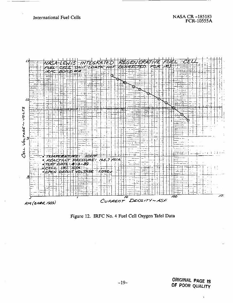
HIE. IRFC No. 4
NASA CR -185183FCR-10555A
The integrated unit incorporated 20-mil (.5 mm) thick asbestos matrix in the fuel cell unit and
electrolysis cell unit. Other than the matrix, the configuration of IRFC No. 4 was identical to
IRFC No. 3. Details of the unit construction are presented at the beginning of Section III.
Following external pressurization to 60 psia (41.4 n/cm 2) and heatup to 200°F (93.3°C), a
charge cycle was initiated by operating the electrolysis cell for 2.5 hours at 200 ASF (215.3
ma/cm2). The fuel cell unit then operated for about 1.5 hours at 200 ASF (215.3 ma/cm2). A
graphic log of the test is shown on Figure 11. As shown on Figure 11, the open circuit voltage
(OCV) of the electrolysis cell fell below 1.0V during discharge. As experienced on IRFC No.
3, the pressure charge/discharge rates experienced on IRFC No. 4 suggests an equivalent 45
ASF (48.4 ma/cm 2) electrical short. However, there was no evidence of an internal electrical
short in the performance data of the fuel cell and electrolysis cell as shown on Figures 12 and
13 respectively. Electrical isolation tests of the instrumentation, tierods, and plumbing isola-
tors did not locate a shorting path. Checkout of the load system, showed the unit to be func-
tioning properly. Following the tests, IRFC No. 4 was shut down and depressurized to ambi-
ent.
A second charge/discharge operating cycle was conducted on IRFC No. 4. Upon pressuriza-
tion to 60 psia (41.4 n/cm 2) and heatup to 200*F (93.3"C), the charge cycle was initiated by
operating the electrolysis cell for 2.5 hours at 200 ASF (215.3 ma/cm2). The fuel cell unit was
next operated for about an hour at reduced loads because of decreasing cell voltage as shown
on Figure 14. Fuel cell OCV following the testing was stable at above 1.10 volts.
Four significant observations can be made from the test. During electrolysis cell operation,
fuel cell open circuit voltage remained above 1.0 volt and improved as system pressure in-
creased. Reactant pressure increase with electrolysis operation, or charge rate was 43.2 psi/hr
(29.8 n/cm 2 hr) consistent with past test experience. During fuel cell operation, the open cir-
cuit voltage of the electrolysis cell approached the operating voltage of the fuel cell. There
was no consumption of reactants during a 35-minute period without load on the fuel cell and
electrolysis cell as reactant pressure held at 132 psia (91.0 n/cm2). The initial performance of
the fuel ceil unit during cycle No. 2 was consistent with cycle No. 1, however, continued opera-
tion during cycle No. 2 contributed to a reduction of fuel cell performance. After the second
charge/discharge cycle, all testing of IRFC No. 4 was stopped.
-16-

International Fuel Cells NASA CR -185183FCR-10555A
Electrical isolation tests of the instrumentation, tierods, and plumbing isolators did not iden-
tify a shorting path. Laboratory checkout of the power supply load system again showed the
unit to be functioning properly.
The anomalous pressurization characteristics appears to be due to internal reactant cross
leakage, with reactant back pressure and internal water management characteristics during
closed cycle operation being contributing factors.
-17-

Figure 11.
._A •
IRFC No. 4 Performance History
-18-ORIGINAL PAGE IS
OF POOR QUALITY
International Fuel Cells NASA CR -185183FCR-10555A
Figure 12. IRFC No. 4 Fuel Cell Oxygen Tafel Data
-19- ORIGINAL PAC.IE !$
OF POOR QUALITY

International Fuel Cells NASA CR -185183FCR-10555A
, ! ,' , , , . ;
...... i -- __ +-+_ -:: - - ++.... +l
I
++'++-+!i_: m--+%--. __ PI+_"t LLIL--':
_t__ :_ :h_I_.-I_::4- - "
:I_-,+.? _ -++.,:: I+-_+-+_+: i +:.,. '
It _:i_:!::i: l? ,+.£ >_
.... ':.:_-_--_--__.!:L t
i..+.- _:+
._--_-+--._-IT-:+J-: +- ._ .*..... 4- +-+....
ZSZ: _[-!_:t::_::i:++.... _.____._:-!--i-ii-i_--I --:,-i-- : F
__:-_ .i:.,:i_:_q_qq, I_;_TiI_;1]i::;;]it;I::;&,i+i,s
:.'2
__ _ I . _.: i-
.... :- "i _ !_
:-:-:i-::J:: _: i',: I-:
.__! .... L +.... :-
.... _L
-,-:-+:-i-;i-:i,;ii:+: it i I ::
Figure 13. IRFC No. 4 Electrolysis Cell Performance
-20- ORIGINAL PAGE IS
OF POOR QUALITY

!::'::
I:,!i
Figure 14. IRFC-4 Graphic Log Cycle No. 2
-21-ORIGINAL PAGE IS
OF POOR QUALITY

International Fuel Cells NASA CR -185183FCR-10555A
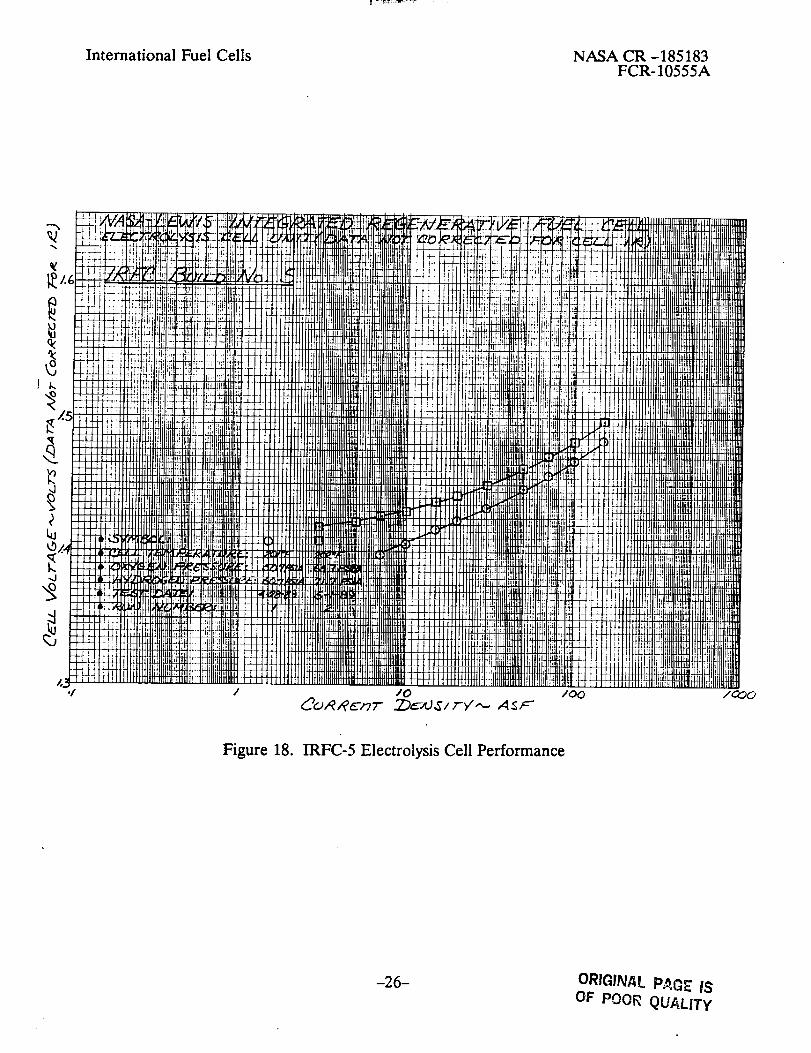
IIIE IRFC No. 5
An exploratory Reversible Fuel Cell was assembled as IRFC No. 5. The purpose of IRFC No.
5 was to determine if the performance anomalies were caused by the IRFC configuration.
IRFC No. 5 incorporated into a single unit both the electrolysis cell and fuel cell functions,
simplified reactant manifolding, reduced water transport requirements, and reduced opera-
tional complexity. Details of the cell construction are presented at the beginning of Section
III.
The graphic log of run No. 1 of IRFC Build No. 5 is presented on Figure 15. Following heat-
up to 200 *F (93.3 *C), the electrolysis cell was operated for about 1.6 hours at 100 ASF (107.6
ma/cm 2) with a normal pressurization rate of 29 psi/hr (20 n/cm 2 hr). The fuel cell unit was
operated for about an hour at 100 ASF (107.6 ma/cm 2) with a normal depressurization rate of
31.6 psi/hr (21.8 n/cm 2 hr). The pressure charge/discharge rates experienced for IRFC No. 5
suggests that the performance anomalies experienced on previous IRFC units was associated
with the two unit integrated laboratory regenerative fuel cell.
The differential pressure imbalance (oxygen above hydrogen) experienced during run 1 was
due to overboard leakage of hydrogen. In order to eliminate the pressure imbalance, oxygen
was vented overboard during operation in the fuel cell mode. Leaking hydrogen system hy-
drogen fittings were repaired and the performance test was resumed.
The graphic log of the second run of IRFC No. 5 is shown on Figure 16. As shown on Figure
16, during electrolysis cell operation the pressurization rate was 24.8 psi/hr (17.1 n/cm 2 hr).
The lower than expected pressurization rate was due to the development of an internal short
during electrolysis cell operation. The magnitude of the cell short, at about 5 ASF (5.4 ma/
cm 2) can be determined from the fuel cell unit Tafel data presented on Figure 17. Electrolysis
cell unit performance is summarized on Figure 18. Performance of the fuel cell during dis-
charge operation was low and unstable, possibly due to internal reactant crossleakage. In
addition, to expedite shutdown of the IRFC, both reactants were periodically vented over-
board as shown on Figure 16.
Due to the internal cell short, IRFC No. 5 was reassembled with new cell components and
refilled with electrolyte. The test plan was to performance evaluate the unit in an open cycle
mode with external supply of reactants and water. However, the NASA Project Manager di-
rected the test not be conducted. At this point all testing of IRFC No. 5, Reversible Cell was
stopped.
-22-

International Fuel Cells NASA CR -185183FCR-10555A
! I
-23- ORIGINAL PAGE IS
OF POOR QUALITY

International Fuel Ceils
i .....
i
Figure 16. IRFC-5 Graphic Log Cycle No. 2
-24-
OF POOR PA_ _.QUALITy

International Fuel Cells NASA CR -185183FCR-10555A
""x
I..
kltb
.J
/./
/.t3
.I
t
.......... 4-
il i i 1
.i._:._ "
] ,/0,0 /C:_.
Figure 17. IRFC-5 Fuel Cell Oxygen Tafel Data
-25- ORIGINAL PAGE IS
OF POOR QUALITY
International Fuel Cells NASA CR -185183FCR-10555A
-d
./ /o
Figure 18. IRFC-5 Electrolysis Cell Performance
-26- ORIGINAL p_(_ 18OF POOR QUALITY

International Fuel Cells NASA CR -185183FCR-10555A
HIG. IRFC No. 6
IRFC No. 6 was assembled with nickel foil bridges over the internal hydrogen ports as shown
on Figure 19. The bridge will prevent Teflon gasket creep into these ports. The NASAProject
Manager suggested that blockage of these ports could result in a reactant cross-pressure dur-
ing electrolysis cell and fuel cell operation. The resulting reactant crossover would explain
the anomalous pressurization charge/discharge rates experienced on past IRFC test unit.
Details of cell construction are presented in Section III.
F/C
Figure 19. IRFC-6 Cell Configuration
-27-
m

International Fuel Cells NASA CR -185183FCR-10555A
IRFC No. 6 was tested in the open cycle mode for over 140-hours at 200"F (93.3"C) and 14.7
psia (10.1 n/cm 2) without incident. In the open cycle mode, water for electrolysis cell opera-
tion was provided from externally supplied humidified reactants. The performance history of
the test is shown on Figure 20. The performance of the fuel cell and electrolysis cell was in-
variant during the test as shown on Figures 21 and 22 respectively.
'-: g)_i-i !_,/_ !,^
i : !
-!f ;
l-!-
m
:sT
Ill
"-i II
I J_
- F-1 ¸
-H
"i' i
-! F_I
___1.
_.i._
4-t
I I.
:4 _-JU!1
1
i,
i .
1
- :i f .....
4 i-_- 1
i
_ . __L_J• I !
• L.
-_ _--_
--i :t-'5:--]
1
I iz _L:_...J: _1___J
i :1-It ....; . Jl
i.+--- .... +-+
-+-4 +- _ ....
, , ::! -:t::tq_::::: ....
-t LdS-i
! : i
::,' i :2 i:1 :?:£
I:1 i .! I.LLI
--Tq:i i i: ]-4_ i I t: I ±
_i: !!:
i : I i ,
I I .i__j r J : - ,
-1-- i
.+--
tI
L .....t :
-I
I
-L_t;i]
4 ::i 2
! !
:: Ai
_t I :.i-_--_ _
,.LJ ,,-4i; ]
_!
_ i 4.- _ _--
i l _: i..... i--
_ ] 2 - I.....t _-_ .... F-
it P- -=- _- 'L
:-_L : 'r-.....!_ r:_ -: lr L-- :=
:.L L
i _ t: L:l:: ;:: t__ :: c: "
::_]::1 _':ff]i [_i :f
....... $i:;::_ !!_ _i
:L] : G: ::i ::;
--,I--, -- :i : :
,: i x
Figure 20. IRFC-6 Open Cycle Performance History
-28-ORIGINAL PAGE iS
OF POOR QUALITY

International Fuel Cells NASA CR -185183FCR-10555A
i0 / O0
Figure 21. IRFC-6 Electrolysis Cell Performance (Open Cycle)
-29- ORIGINAL PAGE ISOF POOR QUALITY

International Fuel Cells NASA CR -185183FCR-10555A
'_ ..5- z 9- d_9
/o /oo /OOC
Figure 22. IRFC-6 Electrolysis Cell Performance (Open Cycle)
-30-

International Fuel Cells NASA CR -185183FCR-10555A
Open cycle test results on IRFC-6 verify the functional capability of the fuel cell and electroly-
sis cell units, individually.
Prior to operating IRFC No. 6 as an integrated unit, the power supply load system and IRFC
test bench were reinspected. As before, no ground loss or external shorting paths were identi-
fied. Following heat-up to 200*F (93.3"), the electrolysis cell was operated dosed cycle for
nearly 40 minutes at 100 ASF (107.6 ma/cm 2) with no increase in reactant pressure. Electroly-
sis cell voltage at 100 ASF (107.6 ma/cm 2) was 1.503V consistent with open cycle test results.
The fuel cell open circuit voltage was about 0.950V. Based upon open cycle Tafel data, this
voltage was equivalent to a 50 ASF (53.8 ma/cm 2) short. At this point, testing on IRFC No. 6
was concluded.
-31-

International Fuel Cells
IV. ELECTROLYSIS CELL ENDURANCE TESTING
NASA CR -185183FCR-10555A
Two laboratory 2-inch x 2-inch (5.1 cm x 5.1 cm) active area electrolysis cells were endurance
tested at a current density of 100 ASF (i07.6 ma/cm2), at a 170*F (76.7"C) cell temperature
and 14.7 psia (10.1 n/cm 2) reactant pressure. The test setup of the laboratory electrolysis cell
is shown on Figure 23.
Ao - PLA ;rED A/t
Alo-I',qEA_D GP, APHITE ERP , .... , ...... • ..._'_ ,,_,, ',: _'., .,,¢. - ,, . ;.
_ L_A T/'IOD£ CA TAL Y5 T("_C'Z [t,'Ol.,) o
.,.SOZ_T,o__7-E: • _ _ _- .... _..... . :_Ao - PLA TED N,, " F'OIL ___
PO FA SS/U/v'I 7"/TAAJATE NA TR/X ..__/_h.,DLAFED /_1/-_/£. _._(jL:_,57-,_ATT=I._..,4 _ I o o oo oo oo o
A oDE cAtAlyst +_/-?z_rEo ,a/,-_'O/L c'o/oDUcro_.// ,_z _z ozELECT"ROL h/ E _RR/F--R(f _O
Figure 23. Laboratory Electrolysis Cell Test Setup105.194
-32-

International Fuel Cells NASA CR -185183FCR-10555A
The configurations of the two electrolysis cells is presented in Table III.
Table III. Electrolysis Cell Configuration Summary
ElectrolysisCell No. ERP H2 Elec. Matrix
1 75 mil C PtPd/Ni-Foil 8-mil PKT
2 75 mil C PtPd/Ni-Foil 8-mil PKT
0 2 Elec.
NiCo 2 O4/Ni-Foil
Noble Alloy/Ni-Foil
The nickel foil substrate employed at the H2 electrode was gold-plated and the nickel foil at
the 02 electrode was Rh-plated. Both cells incorporated a porous Teflon membrane cover on
the anode to prevent electrolyte loss during 02 evolution.
IV.A Electrolysis Call No. 1
The performance history of electrolysis Cell No. 1 is presented on Figure 24. The endurance
test was voluntarily stopped after 307 hours of testing at 170"F (76.7"C) and ambient pres-
sure. The initial cell voltage at a current density of 100 ASF (107.6 ma/cm 2) was i.538V and
after 307 hours of testing, cell voltage was 1.549V.
Test results from performance calibrations at 20 load hours and 233 load hours is summarized
on Figure 25. During the endurance test cell iR was stable at 16 mV at 100 ASF (107.6 ma/
cm2).
Teardown inspection of electrolysis cell No. 1 found all components to be in good condition.
There was no evidence of free electrolyte on the oxygen side of the anode Teflon cover mem-
brane.
-33-

International Fuel Cells NASA CR -185183FCR-10555A
Figure 24. Electrolysis Cell No. 1 Performance History
-34-ORfGrNAL PAGE IS
OF POOR QUALITY

International Fuel Cells NASA CR -185183FCR-10555A
Figure 25. Electrolysis Cell No. 1 Performance Calibration
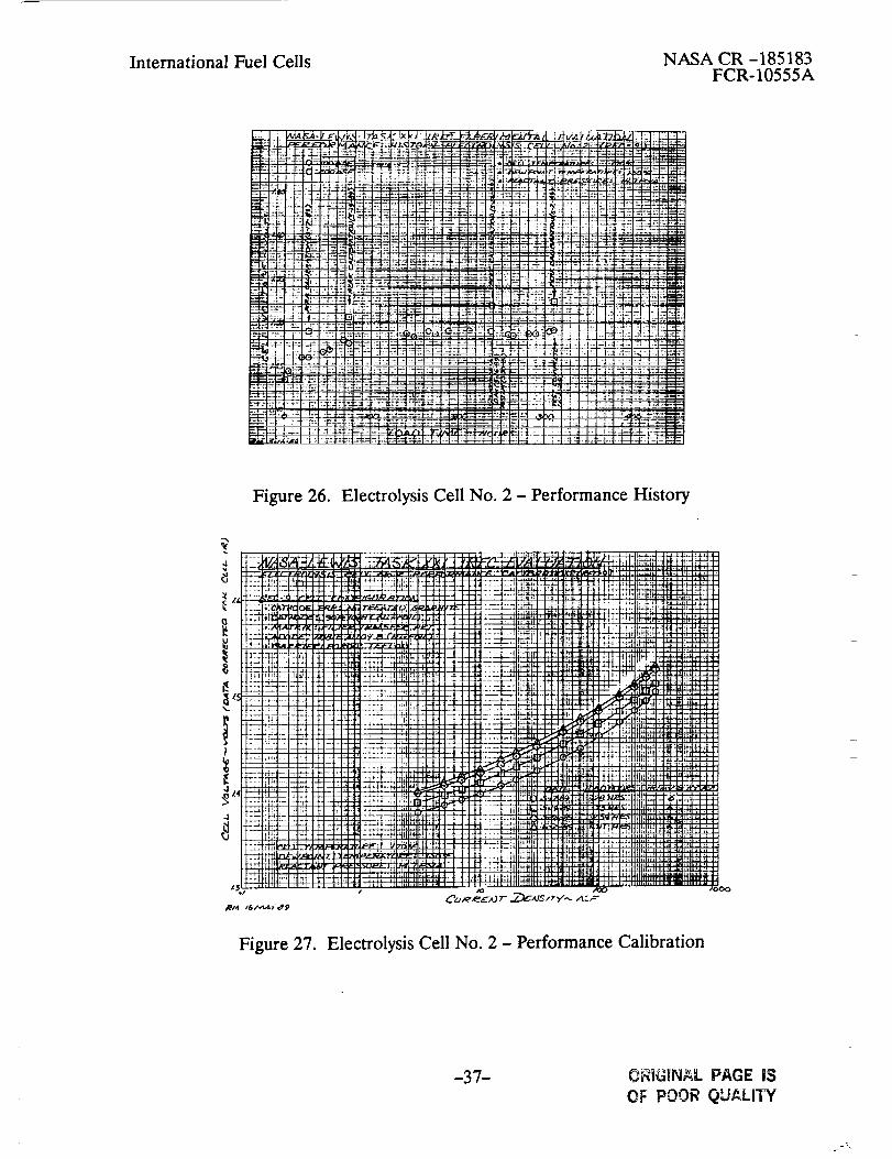
IV.B Electrolysis Cell No. 2
The performance history of Electrolysis Cell No. 2 is presented on Figure 26. The endurance
test was voluntarily stopped after 312-hours of testing at 170*F (76.7"C) and ambient pres-
sure. The initial cell voltage at a current density of 100 ASF (107.6 ma/cm 2) was 1.434V and
after 312-hours of testing, cell voltage was 1.492V.
-35-ORIGINAL PAGE IS
OF POOR QUALITY

International Fuel Cells NASA CR -185183FCR-10555A
Test results from four performance calibrations are summarized on Figure 27. During the
endurance test, cell iR was stable at 6 mV at 100 ASF (107.6 ma/cm2). The stable perform-
ance of Electrolysis Cell No. 2 Over a period of 200-hours of operation represented a 50 mV
improvement over Electrolysis Cell No. I which contained a NiCo204 catalyst O2 electrode.
-36-
International Fuel Cells NASA CR -185183FCR-10555A
-M:{: +,_;_
_!): i
:gL:
:1:_:+-_4+::_'.: q- -
++_-+_.=
"' I i _+.
:_ +- r.+
, i :I _l
1-4.'=_
_q2 -IC-++-_+ .+ +_,
q_qq+ +-,.
t ":l :-_I
Figure 26. Electrolysis Cell No. 2 - Performance History
:I_:_
I _HI!
!!'!H
:+.-+':-t+--
I_ &' :I::,,,._ .....
--+ + t
,,.,,--I_-
++z!¢ -HI!ill Ill
+'-'+- + 1-!t+_'_ m:::+ml
"++ :r bt"
i-1= FI- t_
; u=+_N
bb _
LL i;lb._ t_
_e Mp_-N
r,' !_
Figure 27. Electrolysis Cell No. 2 - Performance Calibration
-37- ORIGINAL PAGE iS
OF POOR QUALITY
International Fuel Cells NASA CR -185183FCR-10555A
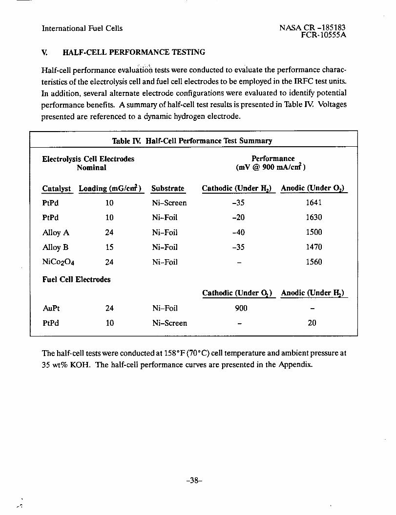
V. HALF-CELL PERFORMANCE TESTING
Half-cell performance evaluation tests were conducted to evaluate the performance charac-
teristics of the electrolysis cell and fuel cell electrodes to be employed in the IRFC test units.
In addition, several alternate electrode configurations were evaluated to identify potential
performance benefits. A summary of half-cell test results is presented in Table IV.. Voltages
presented are referenced to a dynamic hydrogen electrode.
Table IV. Half-Cell Performance Test Summary
Electrolysis Cell Electrodes PerformanceNominal (mY @ 900 mA/cm 2 )
Catalyst Loading (mG/crt_) Substrate Cathodic (Under H_)
PtPd 10 Ni-Screen -35
PtPd 10 Ni-Foil -20
Alloy A 24 Ni-Foil -40
Alloy B 15 Ni-Foil -35
NiCo204 24 Ni-Foil -
Fuel Cell Electrodes
Anodic(UnderO_)
1641
1630
1500
1470
1560
Cathodic (under O_) Anodic (under I-I_)
AuPt 24 Ni-Foil 900 -
PtPd 10 Ni-Screen - 20
The half-cell tests were conducted at 158"F (70" C) cell temperature and ambient pressure at
35 wt% KOH. The half-cell performance curves are presented in the Appendix.
-38-

_r_

NASA CR - 185183FCR-10555A
APPENDIX
ELECTRODE HALF-CELL PERFORMANCE
CURVES

r
p
m
f_

International Fuel Cells NASA CR -185183FCR-10555A
APPENDIX
The half-cell performance of the fuel cell AuPt catalyst cathode and PtPd catlayst anode was
consistent with current production cell performance characteristics. The performance of the
NiCo204 catalyst O2 evolution electrode and PtPd catalyst H2 evolution electrode was consis-
tent with previous IFC exploratory test resttl ts. "la ble V identifies the curves for the complete
half-cell performance test results for the eleven electrodes tested.
Table V. Electrode Half-Cell Performance Curves
Figure No.
28
29
30
31
32
33
34
35
36
37
38
Description
PtPd (Ni-Screen) 02 Evolution Electrode
PtPd (Ni-Foil) O2 Evolution Electrode
Alloy A (Ni-Foil) 02 Evolution Electrode
Alloy B (Ni-Foil) 02 Evolution Electrode
NiCo204 (Ni-Foil) O2 Evolution Electrode
PtPd (Ni-Screen) H2 Evolution Electrode
PtPd (Ni-Foil) H2 Evolution Electrode
Alloy A (Ni-Foil) H2 Evolution Electrode
Alloy B (Ni-Foil) H2 Evolution Electrode
AuPt (Ni-Foil) O2 Consumption Electrode
PtPd (Ni-Screen) H2 Consumption Electrode
Results from the half-cell tests confirm the suitability of the fuel cell and electrolysis cell elec-
trodes baselined for use in the IRFC test units.
1-1

International Fuel Cells NASA CR -185183FCR-10555A
f -
!..
tL-t
..?
. •
.... I
105-183890501
Figure 28. Half Cell Performance - PtPd (Ni-Screen) 02 Evolution Electrode
]-2 ORIGINAL PAGE IS
OF POOR QUALITY

International Fuel Cells NASA CR -185183FCR-10555A
2_ O0 .......
"lip .....
-- _.j
22 /
..j :
:ii _iI :
......... , . +
- : ::: ::: :::i̧
, .... q 3 21 ""
!:7. !z2 .... ,
"- "'/.:
" !:":I ..... ,"_:: ::
......... ;. :.i: L'
- ! "
.... t -
.i ....
i:.:i '...... I ....
.... :|,:,-
I,o,
.... IL.:.
.... i,r..
:::! ....
11 Tas_
per_uzr ' Tie n_b'_
el, 1 :_,:l
.... _;;
[
• . ; : :;l
..... "!
• . , . . _r, T
i!!l:!1..........:::; ::1 '
i
,/: ........ ,.._.-...
L! ................
.., ::: ,...,....,-..
_ :: ..............• - r " ,..-d - +--_. -
:::i _: _::I .I:
:_j r:! *.+.+e..-+-=,,,
i8 ,:i ................
_il _; ..,._,..,.-4 ..,
• .i i !._ ,--_-_ ,_,.,
"T! :!l _'"÷"+_'"
,- : : : :
,l_.,,_. +.--i. -
" : : : : -
I 'S--, --:'.: IR_!_ P
.... i-
• . .+ ..,
• , I°*-.,
• . ;tl ....
'Ii .....
L
: i
:: i_ :!
"'" T
'- v
:: :.i :.L.... i i• :i t..... I',.: ii]!:s _ gi..... I
,. L
• •! .i
i?i ii: :i_
?!i :: !!i!
!ii : :l
O.
Figure 29. Half Cell Performance - PtPd (Ni-Foil) 02 Evolution Electrode
]-3
OF POOR QUALrTY

International Fuel Cells NASA CR -185183FCR-10555A
105-185
890501
Figure 30. Half Cell Performance -Alloy A (Ni-Foil) 02 Evolution Electrode
I-4
ORIGINAL PAGE IS
OF POOR QUALITY

International Fuel Cells NASA CR -185183FCR-10555A
105-186
890501
Figure 31. Half Cell Performance - Alloy B (Ni-Foil) 02 Evolution Electrode
1-5ORrC_NAL PAGE IS
OF PO0_ QUALITY

International Fuel Cells NASA CR -185183FCR-10555A
:7777
i T,_tpera
I " ! i
International Fuel Cells NASA CR -185183FCR-10555A
!05-188
890501
Figure 33. Half Cell Performance - Pt Pd (Ni-Screen) H2 Evolution Electrode
1-7 OR_QINAL PAGE. IS
OF PO0_ QUALITY

International Fuel Cells NASA CR -185183FCR-10555A
i;l
FT -_
i
1 !
; Ii
I.... i
-+- -4.
;F: ;I !
I
iit.;: !L- F
C ;I::.F.rI;;; ]::
2.2 _
lii::_i .... r
i-!i !!!.... I..... i•_
105-189
890501
0
Figure 34. Half Cell Performance - PtPd (Ni-Foil) H2 Evolution Electrode
1-8 ORIGINAL PAGE IS
OF POOR QUALITY

International Fuel CellsNASA CR -185183
FCR-10555A
105-190
890501
Figure 35. Half Cell Performance - Alloy A (Ni-FoiI) H2 Evolution Electrode
1-9 ORIC4NAL PAGE IS
©_ POOR QUALITY

International Fuel Cells NASA CR -185183FCR-10555A
I05-191890501
Figure 36. Half Cell Performance - Alloy B (Ni-Foil) H2 Evolution Electrode
1-10
ORIGINAL PAGE IS
OF POOR QUALITY

International Fuel Cells NASA CR -185183FCR-10555A
-i; ,_:!I1:iii!: :_: ::!: :: :¸ 'i'::'-: I ;:'_ i
: _il:: I! iMI_1.!1::t: :' q_ ! I_1!1
::ii:I:I- _.::I:::'..::::] ......I::_'=Vd,,_l:,'_.....:! i_"l":"i" I- '!................: .....I.:-i. :.....!_,o..._- :,:,....:.I........:::_..:I,:-_:_-::I[._1
L'' I I:' i l:-
.......,-:::J:i! !
I
.-. I: .......
I t
' ----'+---.4
........ i:-i
::; j I
,ao..,.i,,.,_L:.liL
; !
i ,
! ..... I....
'°:':i .... i:i
-T__!I::l-i'
-4- --; ....... i
_i _ _ :!_
-_.-. .
:I .._...... iil:.:-I::..: :- :;.I-.i
':','.r:l:l_Ii
iZtZ
• I
I.
*1
' ii:i _i... i-4-_ _
T!-i i ' "
' iioo105-'192B90501
Figure 37. Half Ceil Performance - AuPt (Ni-Foil) 02 Consumption Electrode
1-1l
ORIGINAL PAGE IS
OF POOR QUAL!Ty

International Fuel Cells NASA CR -185183FCR-10555A
!4!I1¢! I1,IIiii;!
"tilt ' i i i,,II_ittltl_
::_I'._I:!:2
"!!_l!!!!!!r!!._k_ illll II i.I
!!,!_!!!!1!r _ t' )¢it
N_I_IIIIN !)fi t;.i.1_ i l, ii i ,i.i
lli,4_l, il t t iii fill
l#]lltltlllir;"l
_i1111!Ni_il!_:•i
_2:::£i. ! :!...............:tl.............Iti_14;i_1
..............:t]:i
..............11
" !l_k,_fl'llrT
105-193890501
Filure 38. Half Cell Performance - PtPd (Ni-Screen) H2 Consumption Electrode
1-12 ORIGINAL PAGE IS
OF POOR QUALITY

REFERENCES

=
Z
International Fuel Cells NASA CR -185183FCR-10555A
REFERENCES
1. Levy, A., VanDine, L, and Stedman, J., "Regenerative Fuel Cell Study for Satellites in
GEO Orbit - Final Report," International Fuel Cells Corporation, FCR-8347, NASA
CR-179609, December 1986.
2. Martin, R.E., and Manzo, M.A., '_dkaline Fuel Cell Performance Investigation,"
889498, 23rd Intersociety Energy Conversion Engineering Conference, Denver, Colora-
do, August 1988.
3. Sheibley, D.W., and Martin, R.E., '_dvanced Technology for Extended Endurance Alka-
line Fuel Cell," 168th Electrochemical Society, Inc. Meeting, Las Vegas, Nevada, Octo-
ber 1985.
o
e
o
1
t
e
10.
Martin, R.E., Garow, J., and Michaels, K.B., "Regenerative Fuel Cell Energy Storage
System for a Low-Earth Orbit Space Station-Topical Report", United Technologies Cor-
poration, Power Systems Division, FCR-6128, NASA CR-174802, August 1984.
Martin. R.E., '7_lkaline Fuel Cells for the Regenerative Fuel Cell Energy Storage Sys-
tem," 839250, 18th Intersociety Energy Conversion Engineering Conference, Orlando,
Florida, August 1983.
Martin, R.E., Sheibley, D.W., and Gitlow, B., '_lkaline Regenerative Fuel Cell Energy
Storage System for Manned Orbital Satellites," 829361, 17th Intersociety Energy Con-
version Engineering Conference, Los Angeles, CA, August 1982.
Martin, R.E., "Electrochemical Energy Storage for an Orbiting Space Station - Topical
Report," United Technologies Corporation, Power Systems Division, FCR-3142, NASA
CR-165436, December 1982.
Martin, R.E., "Advanced Technology Lightweight Fuel Cell Program - Final Report,"
United Technologies Corporation, Power Systems Division, FCR-3045, NASA
CR-165417, August 1981.
Martin, R.E., Reid, M.A., and Schubert, EN., "Alkaline Regenerative Fuel Cell Systems
for Energy Storage," 819041, 16th Intersociety Energy Conversion Engineering Confer-
ence, Atlanta, GA, August 1981.
Martin, R.E., '_dvanced Technology Lightweight Fuel Cell Program - Final Report,"
United Technologies Corporation, Power Systems Division, FCR-1657, NASA
CR-159807, March 1980.
1-13

International Fuel Cells NASA CR -185183FCR-10555A
11. Martin, R.E., "Advanced Technology Lightweight Fuel Cell Powerplant Components
Program - Final Report," United Technologies Corporation, Power Systems Division,
FCR-1656, February 1980.
12. Martin, R.E., '_Mlvanced Technology Lightweight Fuel Cell Program - Final Report,
"United Technologies Corporation, Power Systems Division, FCR-1017, NASA
CR-159653, September 1979.
13. Martin, R.E., Gitlow, B., and Bell, W.E, "Strip Cell Test and Evaluation Program - Final
Report," United Technologies Corporation. Power Systems Division, FCR-0945, NASA
CR-159652, September 1979.
14. Martin, R.E., Gitlow, B., Meyer, A.E, and Bell, W.F., "Development of Advanced Fuel
Cell System- Final Report," United Technologies Corporation, Power Systems Division,
FCR-0398 NASA CR-159443, June 1976.
15. Meyer, A.P., and Bell, W.E, "Development of Advanced Fuel Cell System (Phase IV) -
Final Report," United Technologies Corporation, Power Systems Division, FCR-0165,
NASA CR-135030, January 1976.
16. Handley, L.M., Meyer, A.E, and Bell, W.E, "Development of Advanced Fuel Cell System
(Phase III)- Final Report," United Aircraft Corporation, Pratt & Whitney Aircraft Divi-
sion, PWA-5201, NASA CR-134818, January 1975.
17. Handley, LM., Meyer, A.P., and Bell, W.E, "Development of Advanced Fuel Cell System
(Phase II) - Final Report," United Aircraft Corporation, Pratt & Whitney Aircraft Divi-
sion, PWA-4984, NASA CR-134721.
18. Grevstad, EE., "Development of Advanced Fuel Cell System - Final Report," United
Aircraft Corporation, Pratt & Whitney Aircraft Division, PWA-4542, NASA CR-121136.
1-14

NASA CR --!8.:_ 1__FCR-10555A
NASA DISTRIBUTION LIST
z


International Fuel Cells FCR-10555A
NASA DISTRIBUTION LIST
ALKALINE FUEL CELL REPORTS
NASA HEADQUARTERS
Mr. Gary Bennett, Code RPNational Aeronautics and Space
Administration
Washington, DC 20546
Mr. Dean Sheibley, MS 500-222Lewis Research Center
National Aeronautics and SpaceAdministration
21000 Brookpark RoadCleveland, OH 44135
National Aeronautics and SpaceAdministration
Scientific and Technical Information
FacilityP.O. Box 8757
Baltimore-WashingtonInternational Airport, MD 21240
(25 copies)
LEWIS
Contracting OfficerRobert Firestone
National Aeronautics and SpaceAdministration
Lewis Research Center, MS 500-305
21000 Brookpark RoadCleveland, OH 44135
Mr. Mark A. Hoberecht, MS 500-222Lewis Research Center
National Aeronautics and SpaceAdministration
21000 Brookpark RoadCleveland, OH 44135
Ms. Lorra Rieker, MS 500-222Lewis Research Center
National Aeronautics and SpaceAdministration
21000 Brookpark RoadCleveland, OH 44135
Dr. J. Stuart Fordyce, MS 3-5Lewis Research Center
National Aeronautics and SpaceAdministration
21000 Brookpark RoadCleveland, OH 44135
Mr. Norman Hagedom, MS 301-3Lewis Research Center
National Aeronautics and SpaceAdministration
21000 Brookpark RoadCleveland, OH 44135 (2 copies)
Mr. Paul Prokopius, MS 301-3Lewis Research Center
National Aeronautics and SpaceAdministration
21000 Brookpark RoadCleveland, OH 44135
Library, MS 60-3Lewis Research Center
National Aeronautics and SpaceAdministration
21000 Brookpark RoadCleveland, OH 44135
International Fuel Cells FCR-10555A
Report Control Office, MS 5-5Lewis Research Center
National Aeronautics and SpaceAdministration
21000 Brookpark RoadCleveland, OH 44135
AIR FORCE
Mr. Joseph P. FellnerAir Force Aero Propulsion LabWRDC/P005-2
Wright Patterson AFB, OH 45433
JOHNSON
Mr. Michael Le, Mail Code EP5
Johnson Space CenterNational Aeronautics and Space
Adminstration
Houston, TX 77058
EIC, Inc.Attn: Dr. B. Brummer
55 Chapel StreetNewton, MA 02158
PRIVATE ORGANIZATIONS
Energy Research CorporationAttn: Mr. B. Baker3 Great Pasture Road
Danbury, CT 06810
Life Systems, Inc.Attn: Dr. R. A. Wynveen24755 Highpoint RoadCleveland, OH 44122
2
NASA ,TR --185183FCR-i0555A
NASA C-168 (REV. 10-75)

m
E
m_

1. Report No. 2. Government Acce_ion No. 3. Rectpieat's Catalog No.
NASA CR-1851834.
9.
Title and Subtitle
Final Report, Task XXIIntegrated Regenerative Fuel CellExperimental Evaluation
Author(0
R. E. Martin
Pefformtag Orgtni_ion Name aad Addrms
INTERNATIONAL FUEL CELLS CORPORATION
195 Governors HighwayRO. Box 739SouthWindsor,Connecticut06074
12. Spomori_ Agency Ntme and Addreu
NATIONAL AERONAUTICS AND SPACE ADMINISTRATIONLewis Research Center21000 Brookpark RoadCleveland, Ohio 44135
5. Report Date
1990
6. Pefformimg Organization Code
8. PedormLug Organization I_n No.
FCR-1055$A
10. Work Unit No.
11. Contn_ or Grant No.
NAS3-22234
13.Type of Report and Period _
Final Report
11 January 1988 - 30 June 1989
14. Sponsoring Agency Cock
506.55.52
IS. Supp_ Notes
NASA Project Manager, Mr. Norman Hagedorn, Mail Stop 301-3NASA-Lewis Research CenterCleveland, Ohio 44135
16. Alstract
An experimental test program was conducted to investigate the performance characterLstics of an Integrated
Regenerative Fuel Cell (IRFC) concept. The IRFC consists of a separate fuel cell unit and electrolysis cell unit
in the same structure, with internal storage of fuel cell product water and external storage of electrolysis cell
produced hydrogen and oxygen. The fuel cell unit incorporates an enhanced Orbiter-type cell capable of im-
proved performance at reduced weight. The electrolysis cell features aNiCo204 catalyst oxygen evolution elec-
trode with a porous Teflon cover to retard electrolyte loss. Six complete IRFC assemblies were assembled and
performance tested at an operating temperature of 200°F (93.3°C) and reactant pressures up to 170 psia (117.2
rdcm 2) on IRFC No. 4. Anomalous pressure charge/discharge characteristics were encountered during per-
formance evaluation. A reversible fuel cell incorporating aproprietary hi-functional oxygen electrode operated
satisfactory at 200°F (93.3°C) at reactant pressures up to 60 psia (41.4 n/cm 2) as a regenerative fuel cell for one
cycle, before developing an electrical short in the fuel cell mode. Electrolysis cell 300-hour endurance tests dem-
onstrated the electrolyte retention capability of the electrode Teflon cover and the performance stability of the
hi-functional oxygen electrode at high potential.
17. Key Words (Suggested by Author(s))
Alkaline Fuel CellsHydrogen.Oxygen Fuel CellsRegenerative Fuel Cells
18. Distri_tion Statement
Unclassified - UnlimitedSTAR Category
19.securitycx._. (orthisreport)
Unclassified
20. SecurityClm, dt. (ofthispage)
Unclassified
• For tqde by the National Technical Information See'vice, Springfield, V'trgiaia 22161
21. No. oflPq_
3822. PI'iI_ °
ASA-C 168 (Rev. 10-75)-00184/16/87
