energy storage fuel cell conference paper - nrel storage fuel cell conference paper ... abstract...
TRANSCRIPT

A national laboratory of the US Department of Energy Office of Energy Efficiency amp Renewable Energy
National Renewable Energy Laboratory Innovation for Our Energy Future
Conference PaperEnergy Storage Fuel Cell NRELCP-540-37567
Vehicle Analysis April 2005
Preprint T Markel A Pesaran M Zolot and S Sprik National Renewable Energy Laboratory
H Tataria General Motors Corp
T Duong US Department of Energy
To be presented at the 21st Electric Vehicle SymposiumMonte Carlo MonacoApril 2ndash6 2005
NREL is operated by Midwest Research Institute Battelle Contract No DE-AC36-99-GO10337
NOTICE
The submitted manuscript has been offered by an employee of the Midwest Research Institute (MRI) a contractor of the US Government under Contract No DE-AC36-99GO10337 Accordingly the US Government and MRI retain a nonexclusive royalty-free license to publish or reproduce the published form of this contribution or allow others to do so for US Government purposes
This report was prepared as an account of work sponsored by an agency of the United States government Neither the United States government nor any agency thereof nor any of their employees makes any warranty express or implied or assumes any legal liability or responsibility for the accuracy completeness or usefulness of any information apparatus product or process disclosed or represents that its use would not infringe privately owned rights Reference herein to any specific commercial product process or service by trade name trademark manufacturer or otherwise does not necessarily constitute or imply its endorsement recommendation or favoring by the United States government or any agency thereof The views and opinions of authors expressed herein do not necessarily state or reflect those of the United States government or any agency thereof
Available electronically at httpwwwostigovbridge
Available for a processing fee to US Department of Energy and its contractors in paper from
US Department of Energy Office of Scientific and Technical Information PO Box 62Oak Ridge TN 37831-0062 phone 8655768401 fax 8655765728 email mailtoreportsadonisostigov
Available for sale to the public in paper from US Department of Commerce National Technical Information Service 5285 Port Royal Road Springfield VA 22161 phone 8005536847 fax 7036056900 email ordersntisfedworldgov online ordering httpwwwntisgovorderinghtm
Printed on paper containing at least 50 wastepaper including 20 postconsumer waste
Energy Storage Fuel Cell Vehicle Analysis
Tony Markel Ahmad Pesaran Matthew Zolot Sam Sprik Harshad Tataria Tien Duong
Abstract
Hybridizing fuel cell (FC) vehicles with energy storage (ES) could result in improved performance and fuel economy and reduced cost We analyzed ES needs for a light mid-size car with a hydrogen FC as the main power source We used the ADVISORtrade vehicle simulator with its ES and FC components for the analysis and tested several different drive cycles FC characteristics and different ES to FC power ratios We assumed that at idle the fuel cell is not shut down and consumes enough hydrogen fuel to sustain itself without generating net power Regen braking and vehicle deceleration were the major sources of charging for the ES for later use The optimum fuel economy occurs when peak FC efficiency is around the average power demand for a particular drive cycle There is positive benefit to downsizing the FC if the peak efficiency is shifted toward the typical power operating point We proposed an ES system with 25 kW discharge (12 seconds) 20 kW charge (5 seconds) with available energy of 250 Wh and a 56 kW FC for the light mid-size car The fuel consumption of this hybridized case was about 30 less than fuel cell only case
Keywords energy storage fuel cell simulation HEV (hybrid electric vehicle) regenerative braking
1 Introduction In recent years hydrogen fuel cell (FC) vehicle technology has received considerable attention as a strategy to decrease oil consumption and reduce harmful emissions However the cost transient response and cold performance of FC systems may present significant challenges to widespread adoption of the technology for transportation in the next 15 years Several previous studies have shown that hybridization of FC vehicles with electrochemical energy storage (ES) devices provides cost performance and operational improvements as well as fuel economy benefits that are attractive and should be considered [1 - 4] Among the current pre-production hybrid FC vehicles the Toyota FCHV [5] has a nickel-metal hydride ES system similar to that of the Toyota Prius and the Honda FCX-V4 uses an ultracapacitor ES system that provides regenerative braking and power assist capability [5 and 6] The requirements of the ES for power assist and 42V hybrid vehicles are defined by the United States Advanced Battery Consortium (USABC) and FreedomCAR Program and can be found at wwwuscarcomconsortiaampteamsconsortiahomepagescon-usabchtm
The objectives of this effort were to perform ES modeling with FC vehicle simulations to quantify the benefits of hybridization and to identify a process for setting the requirements of ES for hydrogen-powered FC vehicles for US Department of Energyrsquos Energy Storage Program The analysis was in support of USABC and the FreedomCAR Electrochemical Energy Storage (EES) Technical Team which are developing requirements for ES systems for FC vehicles for the FreedomCAR Program in the United States
It is important to note that the ES sizes recommended here strongly depended on our assumptions Using different vehicle characteristics and requirements fuel cell characteristics and operating strategies would
1
--
--
----
--
--
----
32
2
have resulted in a different set of energy storage requirements However the approach we used here could be applied to other scenarios
Major Assumptions For the vehicle the EES Technical team suggested using an aerodynamic lightweight mid-size car The vehicle was assumed to be similar to average mid-sized cars in the United States such as the Chevrolet Malibu or Chrysler Stratus The weight of the glider (vehicle without powertrain) was assumed to be about 60 of todayrsquos cars to account for future reductions in weight such as using a structural aluminum body The drag coefficient was assumed to be around 025 with a frontal area of 2 m2 and rolling resistance of 0007 The requirements for the car to meet were minimum range of 500 km maximum speed of 160 kmh 0-100 kmh acceleration of 11 seconds and ability to sustain grade of 55 at 88 kmh
For the rest of the assumptions we used the 2010 FreedomCAR Program technical targets [7] for FC ES power electronics traction motor and hydrogen storage systems (Tables 3-7) The fuel was assumed to be hydrogen from compressed hydrogen cylinders For the FC system we assumed a system peak efficiency of 60 at 25 rated power and a system efficiency of 50 at full rated power (designated as FC_FC50_P25) We assumed that the FC system ramps up in power from 10 to 90 in 1 second while it takes 15 seconds to warm up the fuel cell from cold start to the rated power The FC systemrsquos specific power was assumed to be 500 Wkg For the ES system we assumed average specific power of 1200 Wkg and total specific energy of 70 Whkg with 90 round trip efficiency The following tables summarize the assumptions we used
Table 1 Vehicle characteristics Table 2 Vehicle performance requirements Assumption De scriptionAssumption De scription UnitsUnits ValueValue
alalll wheewheell dri ve mdrive miid-d-Vehicle DescriptionVehicle Description size carsize carBase Vehicle Glider MassBase Vehicle Glider MassCargo MassCargo Mass
kgkgkgkg
636636136136
Aero Drag CoefAero Drag Coef 025025Frontal AreaFrontal Area m^2m^2 22Tire SizeTire Size P21560R16P21560R16RoRollling Resi stanceling Resistance 00070007Vehicle RangeVehicle Range kmkm 500500
Table 3 2010 fuel cell system assumptions Table 4 2010 energy storage assumptions
Assumption DescriptionAssumption Description UnitsUnits ValueValueFuel TypeFuel Type -shy-- hydrogenhydrogenFuel Cell Peak EffFuel Cell Peak Effiiciencyciency 6060Fuel Cell Efficiency at 25 PowerFuel Cell Efficiency at 25 Power 6060
Fuel CelFuel Celll EffEffiiciency at Rated Powerciency at Rated Power 5050Fuel Cell System SpecifFuel Cell System Specifiic Powerc Power WkgWkg 500500Fuel Cell System Power DensityFuel Cell System Power Density WLWL 500500Fuel Cell System CostFuel Cell System Cost $kW$kW 10510532 Fuel Cell System 10-90 PowerFuel Cell System 10-90PowerTransient Response CapabiTransient Response Capabilliityty ss 11Time from Start to Full Power OutputTime from Start to Full Power Output Capability (20CCapability (20C)) ss 1515
Assumption Description Units Value Capacity Ah 12 Charge Mode Efficiency 95 Discharge Mode Efficiency 95 Mass per cell kg 0525 Volume per cell L 0245 Packing factor -- 06 Mass factor -- 085 Energy Wh 427 Power W 709 Specific power Wkg 1200 Energy Storage Cost $kW 20
2
646
Table 5 2010 hydrogen storage assumptions Table 6 2010 power electronic assumptions Assumption DescriptionAssumption Description UnitsUnits ValueValueH2 Storage Energy DensityH2 Storage Energy Density kWhkWhLL 1212H2 Storage Specific EnergyH2 Storage Specific Energy kWhkWhkgkg 1515H2 Storage CostH2 Storage Cost $kWh$kWh 4
Assumption Description Units Value Efficiency 95 Specific Cost $kW 5
Table 7 2010 motorcontroller assumptions
Assumption Description Units Value Specific Power (Motor and Controller) kWkg 075 Specific Cost (Motor and Controller) $kW 11 Power Density (Motor and Controller) kWL 353
It is important to note that we assumed that the ldquocombinedrdquo FC and ES hybridized system must meet the performance target requirements of the vehicle (Table 2) which are acceleration top cruising speed and grade To avoid a large ES system we assumed that top cruising speed or grade sustainability was met with power from only the fuel cell
In addition we made the following assumptions about the operation of the vehicle and FC and the roles of ES
bull 700 W of constant accessory loads during idle or operation But during vehicle driving the accessory load requirement is supplied by the FC
bull FC is always ldquoonrdquo even at vehicle stopsidles (ie no startstop operation like in internal combustion engines or hybrid electric vehicles)
bull At idle (or vehicle stops) the hydrogen fuel consumption of the FC was 03 of rated power consumption This means that although there is ldquogrossrdquo power from the FC its auxiliary loads such as compressors and pumps consume all this ldquogrossrdquo power and the ldquonetrdquo power from the FC is zero
bull The ES is used for traction assist during acceleration bull When the FC is downsized the ES provides traction assist during high power transients to meet the
drive cycle power requirements bull The ES system provides traction assist during FC ldquowarmrdquo startup from idle bull The ES provides powerenergy to start the FC from cold starts bull The ES was not used for sustained gradeability bull All or a major portion of the available regenerative braking is captured by the ES for later traction
use We used two regen braking strategies o ES is sized to limit regen power pulse to a ldquofixedrdquo percentage (100 75 or 50) of the peak
regen power observed during a drive cycle Friction braking absorbs the remainder o of regen energy recaptured is based on a ldquodeceleration-raterdquo strategy
A fractional split between driveline and friction brakes defined as a function of deceleration rate is assumed
We assumed that below 1g deceleration force (=98 m2s mass) all braking is driveline (ie it is captured as regen braking) above 3g all braking is friction (ie no regen braking captured)
Between the 1g and 3g the split between drivetrain and regen braking is proportioned linearly
We found that in this strategy the driveline would recapture between 70 and 90 of the available braking energy depending on the drive cycle
3
3 Approach We used the ADVISOR vehicle simulator for the analysis We simulated a range of FC-ES configurations (cases) as shown in Table 8 In all cases we assumed that top cruising speed or grade sustainability was met with power only from the FC This dictated the minimum size of the FC for the power needed for this vehicle The minimum power for the top cruising speed was found to be 47 kW and the minimum power needed for grade sustainability was 34 kW Therefore the minimum FC size was selected to be 47 kW As mentioned before we assumed that the combined ES discharge power and FC power must meet the acceleration and drive cycle requirements In the case of the fuel-cell-only with no ES and no regen capture (Case 5) the vehicle needed 75 kW of power
In Case 1 we picked the smallest FC that is sized for top speed and largest ES (discharge) that when combined with FC power can meet the required acceleration The ES charge capability was sized for maximum regen capture We used a DOE-target FC system that is at its maximum efficiency (60) at 25 rated power and is 50 efficient at full rated power (FC_FC50_P25) In Case 1 we used a deceleration-based strategy discussed in the Assumptions Section Cases 1a through 1c have similar FC and ES power ratios but with different regen capture capability Case 1f is the same as Case 1a but the maximum FC efficiency at 10 rated power (FC_FC50_P10)
In Cases 2 through 4 FC size was increased incrementally while the ES was sized to satisfy acceleration constraints Note that the total mass of the hybrid vehicle in Cases 1ndash3 is less than the FC only case so the vehicle power requirement for acceleration is less than 75 kW as seen in Table 8 Case 5 is with a FC only with maximum efficiency at 25 rated power (FC_FC50_P25) Case 5f is the same as Case 5 with a FC that is most efficient at 10 rated power (FC_FC50_P10) In Cases 5a through 5c while the FC remains at 75 kW ES is added to capture an increasing percentage of peak regen pulse power Our strategy included maintaining the ES state of charge (or energy) and included regen recovery kinetic energy accounting and opportunity to charge and discharge the ES to make the system more efficient ie ES chargedischarge was executed if it made the overall system efficiency better
4
Table 8 Matrix of vehicle configurations evaluated Fuel Cell ESS
Name Description (kW) Regen (kW) Discharge(KW)
Case 1 FC sized for gradetop speed decel regen strategy FC_FC50_P25 47000 34000 25000
Case 1a Case 1 + 100 regen 47000 34000 25000 Case 1b Case 1 + 75 regen 47000 25500 25000 Case 1c Case 1 + 50 regen 47000 17000 25000 Case 1f Case 1a + FC_FC50_P10 47000 34000 25000
Case 2 Fuel cell - sized to 25 point decel regen strategy FC_FC50_P25 54250 34000 18000
Case 2a Case 2 + 100 regen 54250 34000 18000 Case 2b Case 2 + 75 regen 54250 25500 18000 Case 2c Case 2 + 50 regen 54250 17000 18000 Case 2f Case 2a + FC_FC50_P10 54250 34000 18000
Case 3 Fuel cell - sized to 50 point decel regen strategy FC_FC50_P25 61500 34000 12500
Case 3a Case 3 + 100 regen 61500 34000 12500 Case 3b Case 3 + 75 regen 61500 25500 12500 Case 3c Case 3 + 50 regen 61500 17000 12500 Case 3f Case 3a + FC_FC50_P10 61500 34000 12500
Case 4 Fuel cell - sized to 75 point decel regen strategy FC_FC50_P25 69000 34000 7500
Case 4a Case 4 + 100 regen 69000 34000 7500 Case 4b Case 4 + 75 regen 69000 25500 7500 Case 4c Case 4 + 50 regen 69000 17000 7500 Case 4f Case 4a + FC_FC50_P10 69000 34000 7500 Case 5 Fuel cell only - no ess FC_FC50_P25 75000 0 0 Case 5a Fuel cell only plus 100 ess 75000 36000 36000 Case 5b Fuel cell only plus 75 ess 75000 27000 27000 Case 5c Fuel cell only plus 50 ess 75000 18000 18000 Case 5f Case 5 + FC_FC50_P10 75000 0 0
4 Results
41 Energy Analysis As mentioned the analysis showed that the power needed for sustained gradeability of 55 at 100 kmhr was 34 kW and for a top speed of 160 kmh was 47 kW which dictated the minimum size of the fuel cell The power needed for acceleration of 0-100 kmh for the FC-only case was 76 kW We used the ADVISORtrade simulator to analyze the cases in Table 8 for US City (UDDS) US Highway US06 and HYZEM drive cycles The Delta ESS energy to fuel-use ratio was monitored for correcting fuel economy We used multiple parameters to manage the strength of various elements of control We performed Design of Experiments on each case to determine the best parameter settings
Figure 1 shows the results of the adjusted combined city and highway fuel consumption for each of the 25 cases in Table 8 Here are the observations from Figure 1 bull Comparing Case 5 and 5f (FC only cases) with other cases indicates that fuel consumption decreases
as the vehicle is hybridized with ES This is due to capturing and using regen energy for traction to support the drive cycle
bull Most of the time downsizing the FC creates a positive fuel consumption benefit
5
bull Comparing FC only (Case 5) to the best case of the hybridized vehicle (Case 1b) the fuel consumption is reduced from 425 Lit100 km to about 3 Lit100 km or a roughly 30 reduction in fuel consumption This is due to both downsizing and capturing and using regen
bull The lower fuel consumption (higher fuel economy) case occurs when the peak FC efficiency occurs at 10 rated power (comparing cases 5 with 5f 1a with 1f 2a with 2f 3a with 3f and 4a with 4f) This is due to the fact that the average power demand for both city and highway drive cycles is 10-15 of the rated power from the FC and thus the FC is more efficient at 10 rated power than 25 rated power [2]
bull The smaller FC and largest ES gives the lowest fuel consumption (Case 1) bull Adding ES even to a full size FC (Cases 1a-1c) improves the fuel economy since the regen energy is
captured and used later
45
4
35
3
25
2
)
C o m pos ( adjust ed)
Fuel
Con
sum
ptio
n (L
100
km
it e
Figure 1 Fuel consumption of various hybridized FC cases shown in Table 8
Figure 2 shows the impact of energy storage charge acceptance capability on the amount of energy that could be recaptured from regen braking From this and other results not shown due to limited space we can observe the following
bull The reduction of fuel consumption from Case 5 to the cases with added energy storage (5a 5b and 5c) to capture regen is roughly 20 for US06 cycle
bull When limiting energy storage charge acceptance to 18 kW 15 of regen braking could not be captured during the US06 cycles since some of the peak power pulses are more than 18 kW For the city cycle this is only about 6 opportunity loss
bull Increasing the ES charge acceptance to 36 kW to capture almost 98 of available regen has only a small impact on reducing fuel consumption (2 for US06 and even lower for City and Highway cycles)
Case 1
Case 1
a
Case 1
b
Case 1
c
Case 1
f
Case 2
Case 2a
Case 2
b
Case 2
c
Case 2f
Case 3
Case 3
a
Case 3
b
Case 3
c
Case 3f
Case 4
Case 4
a
Case 4b
Case 4
c
Case 4
f
Case 5
Case 5
a
Case 5b
Case 5
c
Case 5
f
6
Bra
king
Los
ses
( o
f fue
l cel
l onl
y ca
se)
Pow
er (k
W)
UDDS Braking LossUS06 Braking LossCharge Power Limit
Largest EES to capture 100 Regen
Small EES to capture 50 RegenMid-size EES
to capture 75 Regen
O
ppor
tuni
ty E
nerg
y Lo
ss(E
nerg
yN
ot C
aptu
red
Tota
lBra
king
Ene
rgy
Ava
ilabl
e fo
r Veh
icle
with
FC
Onl
y)
US06 Fuel Consumption (Lit100km) bull Case 5 (75 kW FC only) = 422bull Case 5a (75 kW FC + 36 kW ES) = 338bull Case 5a (75 kW FC + 27 kW ES) = 341bull Case 5b (75 kW FC + 18 kW ES) = 345
Bra
king
Los
ses
( o
f fue
l cel
l onl
y ca
se)
Pow
er (k
W)
UDDS Braking LossUS06 Braking LossCharge Power Limit
Largest EES to capture 100 Regen
Small EES to capture 50 RegenMid-size EES
to capture 75 Regen
O
ppor
tuni
ty E
nerg
y Lo
ss(E
nerg
yN
ot C
aptu
red
Tota
lBra
king
Ene
rgy
Ava
ilabl
e fo
r Veh
icle
with
FC
Onl
y)
Bra
king
Los
ses
( o
f fue
l cel
l onl
y ca
se)
Pow
er (k
W)
Best Cases
4000
4500
353535 353535
0
25
30
40
Case 5a Case 5b Case 5c 0
25
30
40
0
25
30
40
Case 5a Case 5b Case 5c0
25
30
40
0
25
30
40
Case 5a Case 5b Case 5c
UDDS Braking Loss US06 Braking Loss Charge Power Limit
Largest EES to capture 100 Regen
Small EES to capture 50 RegenMid-size EES
to capture 75 Regen
0
25
30
40
US06 Fuel Consumption (Lit100km) bull Case 5 (75 kW FC only) = 422 bull Case 5a (75 kW FC + 36 kW ES) = 338 bull Case 5a (75 kW FC + 27 kW ES) = 341 bull Case 5b (75 kW FC + 18 kW ES) = 345
O
ppor
tuni
ty E
nerg
y Lo
ss
(Ene
rgy
Not
Cap
ture
d T
otal
Bra
king
Ene
rgy
Ava
ilabl
e fo
r Veh
icle
with
FC
Onl
y )
Cha
rge
Pow
er L
imit
(kW
)C
harg
e Po
wer
Lim
it (k
W)
Cha
rge
Pow
er L
imit
(kW
)
202020202020
151515 151515
101010 101010
555555
Figure 2 Breaking energy not captured because of ES charge acceptance limitations
Since the projected cost of energy storage per unit power is lower than the projected cost of fuel cell per unit power it would also make economical sense to replace some of the fuel cell functions with energystorage We estimated the cost of the powertrain containing the fuel cell system energy storage systempower electronics motor and controller and the hydrogen storage system The size and cost of the hydrogen system was selected so that each vehicle case has a range of 500 km Figure 3 shows the powertrain cost and a figure of merit (fuel economy divided by total powertrain cost) for each of the cases Total cost decreased with decreasing FC size increase and decreasing ES size Figure 3 indicates that Cases 1b or 1c are the best cases to consider since they have the highest fuel economy to powertrain cost
0
1500
2000
2500
3000
3500
Pow
ertr
ain
Cos
t ($)
Energy Storage (20 $kW) Power Electronics (5 $kW) Traction Motor ($12kW) Hydrogen Storage (4 $kWh) Fuel Cell (32 $kW)
002500255000 Best
Cases
lower costlower cost002002
00050005Lower fuelLower fuel
00
HigherHigher fuelfuel
economyeconomy
Figu
re o
f Mer
it (m
pgge
$)
Figu
re o
f Mer
it (m
pgge
$)
00150015
001001
economyeconomyhigherhigher costcost
e 1 a 1b
Case 1
ce 1
f 2 2a
2b 2c 2f e 3 a 3
Case 3
b c 3f e 4 a 4b e 4
c 4f 5 5a b
se5c 5f
11 aa bb 11cc 1f1f 22 aa
ase 2b
ase 2b 22cc 33
se3a
se3a 33bb e 3e 3
cc 3f3f 44 aa bb 44cc 4f4f 55 aa 5b5b 55cce 2e 2ff
e 5e 5ff3 4 5se se 11 11 22 44 44 55se se se se sseeas
eas
eas
eas
eas
eas
eas
eas
eeas se e e e as e e as se e e e ee ee eeas sese sese sese seseCaCasese sese sese sese sese sese sese eeCa as CaCasCas Cas Cas Cas Cas Cas Cas Cas CaCass asas CaCass CaCass CaCassCa Ca CaCa
CaCass CaCassCaa C C CaC CaCa CaCa CaCa CaCaCaCa CaCa CaCa CaCa CaCa CaCa CaCa CaCaCC CC CC CCC CCCC
Figure 3 Total hybrid powertrain cost (left) and fuel economy normalized by powertrain cost
Now that the best case was identified we needed to determine the energy and power requirements of the energy storage system based on the drive cycles
7
500
1000
C C
1
Average Pulse Power
Peak Pulse Power
42 Power Profile Analysis The major question is ldquoHow can we determine ESS requirements for meeting instantaneous power demands for a particular cyclerdquo From the analysis one must come up with the required discharge power for a specified duration required charge power for a specified duration and amount of available energy needed to support the power profile from a drive cycle We analyzed all the drive cycles previously indicated and separated the power demands of the FC and the ES For the ES power profile we overlaid all pulse power events of a driving profile on the same figure with start times set to zero The ranges of the profile shapes were varied some with sharp tall peaks and some broad with multiple small peaks in the middle To simplify the analysis to be able to extract information we assigned the duration of the events for the broad peaks and an associated average pulse power for that peak For the sharp peak portion of each segment we assigned a short duration for the pulse peak power and magnitude of the pulse peak power Figure 4 depicts this representation
Duration at Peak Power
Duration of Event
Duration atPeak Power
Duration of Event
Duration atPeak Power
Duration of Event
Average Pulse Power
Peak Pulse Power
Figure 4 Analysis of energy storage power profile (example is for Case 1 with US06)
The energy captured or needed in each peak was calculated based on the average pulse power times during the duration of the event and is called usable or available energy We then plotted the average pulse power versus the available energy for various cases Figure 5 shows such a plot for various cases
We also looked at the distribution of the energy storage system operating points for all the cycles to estimate mean median and standard deviation for the peak pulse power Peak pulse power and average pulse power were plotted versus the duration of associated event We included the required power for acceleration Figure 6 shows peak pulse and average pulse power as a function of duration for various drive cycles and acceleration It can be seen that peak power events typically only last for short durations of less than 1 second From Figures 5 and 6 we believe that we need an ES system with 25 kW discharge capability for 12 seconds and charge capability of 20 kW for 5 seconds for all the categories in Case 1 Either NiMH or Li-ion batteries could deliver such power and energy capabilities Of course other requirements such as cost cycle life calendar life operating temperature range and self-discharge rate will dictate the final selection Acceleration performance sets discharge requirements and the US06 cycle sets charge requirements We should note that for FC startups (not traction) some FC systems may need up to 10 kW of power for 15 seconds The energy requirements would be 42 Wh So the energy and power requirements for cold startup will be within the capability of the recommended energy storage The startup of the FC vehicles
8
100 regen cases
75 regen cases
50 regen cases
5
from very cold temperatures (below -10degC) with batteries may be challenging since the batteries have limited performance capabilities at low temperatures Ultracapacitors have better performance capabilities than batteries at cold temperatures so it is possible that we may select ultracapacitors over batteries for this reason even though it may not be the most desirable approach
6060R
ated
Pow
er (k
W)
Rat
ed P
ower
(kW
)
5050
4040
3030
2020
1010
0050 100 150 200 250 30050 100 150 200 250 300
100 regen cases
75 regen cases
50 regen cases
100 regen cases
75 regen cases
50 regen cases
Usable Energy Range (Wh)Usable Energy Range (Wh)
Figure 5 Power and associated energy needs for various cases studied
Figure 6 Peak pulse power (left) and average pulse power (right) versus duration for multiple cycles
Concluding Remarks We analyzed ES roles in a FC vehicle Hybridizing a FC vehicle with an ES system improves the fuel economy and reduces cost based on the 2010 DOEFreedomCAR targets for components of a hybrid FC vehicle The ES will also improve vehicle response by supplementing the FCrsquos limited transient response We described a process for determining ES requirements We found that the peak power events for most drive cycles are very brief and less than 1 second In general 25-30 improvement in fuel consumption can be achieved with hybridization As long as the majority of regen is captured regen strategy is not critical The most fuel-efficient scenario was also the least expensive scenario (smallest fuel cell with moderate ESS) Intelligent energy management strategies to utilize captured regen energy in FC hybrid vehicles are critical Fuel consumption is lower with a FC with peak efficiency of around 10 rated
9
power For the lightweight aerodynamic midsize car we proposed an energy storage system with 25 kW discharge (12 seconds) 20 kW charge (5 seconds) and available energy of 250 Wh and a 56 kW FC
We will continue working with the FreedomCAR Technical Teams to further refine the assumptions and the analysis to recommend final requirements for ES for FC hybrids Of interest is the quantification of the energy and power available from a fuel cell system to charge the energy storage during long idles or ramping down of the fuel cell from high to lower power
Acknowledgments The US Department of Energy (DOE) Office of the FreedomCAR and Vehicle Technology supported this effort We appreciate the technical guidance provided by the United States Advanced Battery Consortium and FreedomCAR Electrochemical Energy Storage Technical Team particularly Ted Miller from Ford and Cyrus Ashtiani from DaimlerChrysler
References [1] Markel et al ldquoFuel Cell Energy Storage Analysisrdquo Proceedings of Advanced Automotive Battery Conference San Francisco CA June 4-6 2004
[2] Zolot etal ldquoEnergy Storage Requirements for Hybrid Fuel Cell Vehiclesrdquo Proceedings of Advanced Automotive Battery Conference Nice France June 14-16 2003
[3] Wipke K Markel T Nelson D ldquoOptimizing Energy Management Strategy and Degree of Hybridization for a Hydrogen Fuel Cell SUVrdquo Proceedings of 18th Electric Vehicle Symposium Berlin Germany October 2001
[4] Markel T Wipke K ldquoOptimization Techniques for Hybrid Electric Vehicle Analysis Using ADVISORrdquo Proceedings of the ASME International Mechanical Engineering Congress and Exposition New York New York November 11-16 2001
[5] Yamaguchi J ldquoLeading the Way Fuel Cell Vehicles from Toyota and Honda Are Hitting the Streets for Customer Use in Both Japan and USrdquo Automotive Engineering International March 2003 pp 54-58
[6] Tamernori K Oki N Kato S and Yamamoto K ldquoApplication Studies of Electric Double Layer Capacitor System for Fuel Cell Vehiclesrdquo Third International Advanced Automotive Battery Conference Nice France June 10-13- 2003
[7] DOE- FreedomCAR and Vehicle Technologies and Hydrogen Fuel Cells amp Infrastructure Technologies Programs ldquoMulti-Year Research Development and Demonstration Planrdquo httpwwweereenergygovhydrogenandfuelcellsmypp and httpwwweereenergygovvehiclesandfuelsresourcesfcvt_myppshtml
Authors
Tony Markel Senior Engineer National Renewable Energy Laboratory 1617 Cole Blvd MS 1633 Golden CO 80401 303-275-4478 303-275-4415 tony_markelnrelgov
As part of the vehicle systems analysis team Mr Markel applies computer modeling and simulation to the evaluation of advanced automotive systems He has been instrumental in the development of the ADVISORtrade software tool His technology focus areas include advanced numerical and architectural methods for vehicle systems analysis and fuel cell systems research and
development Before joining NREL in 1996 Mr Markel worked at Argonne National Laboratory on various transportation-related projects He has a BSE in mechanical engineering with an emphasis in fluid and thermal sciences and is currently attending the University of Colorado to pursue a MS in mechanical engineering
10
Ahmad Pesaran Principal Engineer National Renewable Energy Laboratory 1617 Cole Blvd MS 1633 Golden CO 80401 303-275-4441 303-275-4415 ahmad_pesarannrelgov
Dr Pesaran joined NREL in 1983 and has been working on various energy systems such as solar cooling ocean thermal energy conversion air conditioning desiccant dehumidificationcooling for buildings and buses and most recently hybrid electric vehicles Since 1995 he has been working on hybrid electric vehicle projects He is currently the project manager for various activities related to
battery thermal characterization battery thermal analysis and battery modeling and simulations Dr Pesaran holds a BS in chemical engineering from Shiraz University as well as an MS in engineering and a PhD in mechanical engineering from UCLA He is a member of the FreedomCAR Electrochemical Energy Storage Technical Team
Matthew Zolot Research Engineer National Renewable Energy Laboratory 1617 Cole Blvd MS 1633 Golden CO 80401 303-275-4640 303-275-4415 matthew_zolotnrelgov
Matthew Zolot is a research engineer in the Center for Transportation Technologies and Systems (CTTS) at the National Renewable Energy Laboratory He is in CTTS Advanced Vehicle Systems Group supporting the energy storage and advanced power electronics teams Mr Zolot received a BS in electrical engineering from Georgia Institute of Technology and is currently working
toward an MS at the Colorado School of Mines During his engineering career he has been employed at Agilent Technologies in the test and measurement division and Lucent Technologies in the optical network division He has worked on hybrid vehicle mobile data acquisition simulation testing and analyses of hybrid vehicles and components and contributes to the development of NRELs ADVISORtrade vehicle simulator
Sam Sprik Engineer National Renewable Energy Laboratory 1617 Cole Blvd MS 1633 Golden CO 80401 303-275-4431 303-275-4415 sam_spriknrelgov
Mr Sprik works on vehicle systems analysis and the graphic user interface development of ADVISORtrade software NRELs advanced vehicle simulator software He is educated and interested in control theory virtual reality and manufacturing quality While a research assistant at the University of Michigan he measured and analyzed measurement processes at Chrysler on vehicle
body parts He is well versed in MATLABSimulink programming and in Virtual Reality Modeling Language along with some geometric modeling programs Mr Sprik holds a BS in mechanical engineering from Calvin College and an MSME from the University of Michigan
Harshad S Tataria USABC Technical Advisory Committee amp FreedomCAR Program Manager General Motors Corporation 30001 Van Dyke Avenue MC 480-210-427 Warren MI 48092 USA 586-575-3472 586-492-6645 harshadstatariagmcom
Mr Harshad Tataria is a member of both the United States Advanced Battery Consortium (USABC) Technical Advisory Committee and the FreedomCAR Electrochemical Energy Storage Technical Team He is a Staff Project Engineer at General Motors Corp where he is responsible for the
development of energy storage systems for HEVs Mr Tataria has over 30 years of experience in battery development His experience includes Lead-Acid NiMH Li metal primary and secondary and Li-Ion batteries He has obtained many patents and published many papers in various scientific journals
Tien Q Duong Office of FreedomCAR and Vehicle Technologies US Department of Energy 1000 Independence Avenue SW Washington DC 20585 USA 202-586-2210 202-586-1600 (fax) TienDuongeedoegov
Mr Duong is Vehicles Technologies Team Lead at the Department of Energyrsquos FreedomCAR and Vehicle Technologies Program Office Mr Duong received his MS degree in Civil Environmental Engineering and his BS degree in Electrical Engineering from Virginia Polytechnic Institute and
State University in Blacksburg Virginia He is a member of USABC Managing Committee
11
REPORT DOCUMENTATION PAGE Form Approved OMB No 0704-0188
The public reporting burden for this collection of information is estimated to average 1 hour per response including the time for reviewing instructions searching existing data sources gathering and maintaining the data needed and completing and reviewing the collection of information Send comments regarding this burden estimate or any other aspect of this collection of information including suggestions for reducing the burden to Department of Defense Executive Services and Communications Directorate (0704-0188) Respondents should be aware that notwithstanding any other provision of law no person shall be subject to any penalty for failing to comply with a collection of information if it does not display a currently valid OMB control number PLEASE DO NOT RETURN YOUR FORM TO THE ABOVE ORGANIZATION 1 REPORT DATE (DD-MM-YYYY)
April 2005 2 REPORT TYPE
Conference Paper 3 DATES COVERED (From - To)
4 TITLE AND SUBTITLE Energy Storage Fuel Cell Vehicle Analysis Preprint
5a CONTRACT NUMBER DE-AC36-99-GO10337
5b GRANT NUMBER
5c PROGRAM ELEMENT NUMBER
6 AUTHOR(S) T Markel A Pesaran M Zolot S Sprik H Tataria and T Duong
5d PROJECT NUMBER NRELCP-540-37567
5e TASK NUMBER FC056000
5f WORK UNIT NUMBER
7 PERFORMING ORGANIZATION NAME(S) AND ADDRESS(ES) National Renewable Energy Laboratory 1617 Cole Blvd Golden CO 80401-3393
8 PERFORMING ORGANIZATION REPORT NUMBER NRELCP-540-37567
9 SPONSORINGMONITORING AGENCY NAME(S) AND ADDRESS(ES) 10 SPONSORMONITORS ACRONYM(S) NREL
11 SPONSORINGMONITORING AGENCY REPORT NUMBER
12 DISTRIBUTION AVAILABILITY STATEMENT National Technical Information Service US Department of Commerce 5285 Port Royal Road Springfield VA 22161
13 SUPPLEMENTARY NOTES
14 ABSTRACT (Maximum 200 Words) In recent years hydrogen fuel cell (FC) vehicle technology has received considerable attention as a strategy to decrease oil consumption and reduce harmful emissions However the cost transient response and cold performance of FC systems may present significant challenges to widespread adoption of the technology for transportation in the next 15 years The objectives of this effort were to perform energy storage modeling with fuel cell vehicle simulations to quantify the benefits of hybridization and to identify a process for setting the requirements of ES for hydrogen-powered FC vehicles for US Department of Energyrsquos Energy Storage Program
15 SUBJECT TERMS hybrid energy storage fuel cell simulation HEV regenerative braking
16 SECURITY CLASSIFICATION OF 17 LIMITATION OF ABSTRACT
UL
18 NUMBER OF PAGES
19a NAME OF RESPONSIBLE PERSON
a REPORT Unclassified
b ABSTRACT Unclassified
c THIS PAGE Unclassified 19b TELEPHONE NUMBER (Include area code)
Standard Form 298 (Rev 898) Prescribed by ANSI Std Z3918
F1147-E(122004)
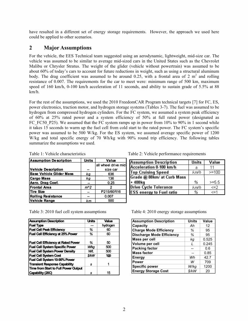
--
--
----
--
--
----
32
2
have resulted in a different set of energy storage requirements However the approach we used here could be applied to other scenarios
Major Assumptions For the vehicle the EES Technical team suggested using an aerodynamic lightweight mid-size car The vehicle was assumed to be similar to average mid-sized cars in the United States such as the Chevrolet Malibu or Chrysler Stratus The weight of the glider (vehicle without powertrain) was assumed to be about 60 of todayrsquos cars to account for future reductions in weight such as using a structural aluminum body The drag coefficient was assumed to be around 025 with a frontal area of 2 m2 and rolling resistance of 0007 The requirements for the car to meet were minimum range of 500 km maximum speed of 160 kmh 0-100 kmh acceleration of 11 seconds and ability to sustain grade of 55 at 88 kmh
For the rest of the assumptions we used the 2010 FreedomCAR Program technical targets [7] for FC ES power electronics traction motor and hydrogen storage systems (Tables 3-7) The fuel was assumed to be hydrogen from compressed hydrogen cylinders For the FC system we assumed a system peak efficiency of 60 at 25 rated power and a system efficiency of 50 at full rated power (designated as FC_FC50_P25) We assumed that the FC system ramps up in power from 10 to 90 in 1 second while it takes 15 seconds to warm up the fuel cell from cold start to the rated power The FC systemrsquos specific power was assumed to be 500 Wkg For the ES system we assumed average specific power of 1200 Wkg and total specific energy of 70 Whkg with 90 round trip efficiency The following tables summarize the assumptions we used
Table 1 Vehicle characteristics Table 2 Vehicle performance requirements Assumption De scriptionAssumption De scription UnitsUnits ValueValue
alalll wheewheell dri ve mdrive miid-d-Vehicle DescriptionVehicle Description size carsize carBase Vehicle Glider MassBase Vehicle Glider MassCargo MassCargo Mass
kgkgkgkg
636636136136
Aero Drag CoefAero Drag Coef 025025Frontal AreaFrontal Area m^2m^2 22Tire SizeTire Size P21560R16P21560R16RoRollling Resi stanceling Resistance 00070007Vehicle RangeVehicle Range kmkm 500500
Table 3 2010 fuel cell system assumptions Table 4 2010 energy storage assumptions
Assumption DescriptionAssumption Description UnitsUnits ValueValueFuel TypeFuel Type -shy-- hydrogenhydrogenFuel Cell Peak EffFuel Cell Peak Effiiciencyciency 6060Fuel Cell Efficiency at 25 PowerFuel Cell Efficiency at 25 Power 6060
Fuel CelFuel Celll EffEffiiciency at Rated Powerciency at Rated Power 5050Fuel Cell System SpecifFuel Cell System Specifiic Powerc Power WkgWkg 500500Fuel Cell System Power DensityFuel Cell System Power Density WLWL 500500Fuel Cell System CostFuel Cell System Cost $kW$kW 10510532 Fuel Cell System 10-90 PowerFuel Cell System 10-90PowerTransient Response CapabiTransient Response Capabilliityty ss 11Time from Start to Full Power OutputTime from Start to Full Power Output Capability (20CCapability (20C)) ss 1515
Assumption Description Units Value Capacity Ah 12 Charge Mode Efficiency 95 Discharge Mode Efficiency 95 Mass per cell kg 0525 Volume per cell L 0245 Packing factor -- 06 Mass factor -- 085 Energy Wh 427 Power W 709 Specific power Wkg 1200 Energy Storage Cost $kW 20
2
646
Table 5 2010 hydrogen storage assumptions Table 6 2010 power electronic assumptions Assumption DescriptionAssumption Description UnitsUnits ValueValueH2 Storage Energy DensityH2 Storage Energy Density kWhkWhLL 1212H2 Storage Specific EnergyH2 Storage Specific Energy kWhkWhkgkg 1515H2 Storage CostH2 Storage Cost $kWh$kWh 4
Assumption Description Units Value Efficiency 95 Specific Cost $kW 5
Table 7 2010 motorcontroller assumptions
Assumption Description Units Value Specific Power (Motor and Controller) kWkg 075 Specific Cost (Motor and Controller) $kW 11 Power Density (Motor and Controller) kWL 353
It is important to note that we assumed that the ldquocombinedrdquo FC and ES hybridized system must meet the performance target requirements of the vehicle (Table 2) which are acceleration top cruising speed and grade To avoid a large ES system we assumed that top cruising speed or grade sustainability was met with power from only the fuel cell
In addition we made the following assumptions about the operation of the vehicle and FC and the roles of ES
bull 700 W of constant accessory loads during idle or operation But during vehicle driving the accessory load requirement is supplied by the FC
bull FC is always ldquoonrdquo even at vehicle stopsidles (ie no startstop operation like in internal combustion engines or hybrid electric vehicles)
bull At idle (or vehicle stops) the hydrogen fuel consumption of the FC was 03 of rated power consumption This means that although there is ldquogrossrdquo power from the FC its auxiliary loads such as compressors and pumps consume all this ldquogrossrdquo power and the ldquonetrdquo power from the FC is zero
bull The ES is used for traction assist during acceleration bull When the FC is downsized the ES provides traction assist during high power transients to meet the
drive cycle power requirements bull The ES system provides traction assist during FC ldquowarmrdquo startup from idle bull The ES provides powerenergy to start the FC from cold starts bull The ES was not used for sustained gradeability bull All or a major portion of the available regenerative braking is captured by the ES for later traction
use We used two regen braking strategies o ES is sized to limit regen power pulse to a ldquofixedrdquo percentage (100 75 or 50) of the peak
regen power observed during a drive cycle Friction braking absorbs the remainder o of regen energy recaptured is based on a ldquodeceleration-raterdquo strategy
A fractional split between driveline and friction brakes defined as a function of deceleration rate is assumed
We assumed that below 1g deceleration force (=98 m2s mass) all braking is driveline (ie it is captured as regen braking) above 3g all braking is friction (ie no regen braking captured)
Between the 1g and 3g the split between drivetrain and regen braking is proportioned linearly
We found that in this strategy the driveline would recapture between 70 and 90 of the available braking energy depending on the drive cycle
3
3 Approach We used the ADVISOR vehicle simulator for the analysis We simulated a range of FC-ES configurations (cases) as shown in Table 8 In all cases we assumed that top cruising speed or grade sustainability was met with power only from the FC This dictated the minimum size of the FC for the power needed for this vehicle The minimum power for the top cruising speed was found to be 47 kW and the minimum power needed for grade sustainability was 34 kW Therefore the minimum FC size was selected to be 47 kW As mentioned before we assumed that the combined ES discharge power and FC power must meet the acceleration and drive cycle requirements In the case of the fuel-cell-only with no ES and no regen capture (Case 5) the vehicle needed 75 kW of power
In Case 1 we picked the smallest FC that is sized for top speed and largest ES (discharge) that when combined with FC power can meet the required acceleration The ES charge capability was sized for maximum regen capture We used a DOE-target FC system that is at its maximum efficiency (60) at 25 rated power and is 50 efficient at full rated power (FC_FC50_P25) In Case 1 we used a deceleration-based strategy discussed in the Assumptions Section Cases 1a through 1c have similar FC and ES power ratios but with different regen capture capability Case 1f is the same as Case 1a but the maximum FC efficiency at 10 rated power (FC_FC50_P10)
In Cases 2 through 4 FC size was increased incrementally while the ES was sized to satisfy acceleration constraints Note that the total mass of the hybrid vehicle in Cases 1ndash3 is less than the FC only case so the vehicle power requirement for acceleration is less than 75 kW as seen in Table 8 Case 5 is with a FC only with maximum efficiency at 25 rated power (FC_FC50_P25) Case 5f is the same as Case 5 with a FC that is most efficient at 10 rated power (FC_FC50_P10) In Cases 5a through 5c while the FC remains at 75 kW ES is added to capture an increasing percentage of peak regen pulse power Our strategy included maintaining the ES state of charge (or energy) and included regen recovery kinetic energy accounting and opportunity to charge and discharge the ES to make the system more efficient ie ES chargedischarge was executed if it made the overall system efficiency better
4
Table 8 Matrix of vehicle configurations evaluated Fuel Cell ESS
Name Description (kW) Regen (kW) Discharge(KW)
Case 1 FC sized for gradetop speed decel regen strategy FC_FC50_P25 47000 34000 25000
Case 1a Case 1 + 100 regen 47000 34000 25000 Case 1b Case 1 + 75 regen 47000 25500 25000 Case 1c Case 1 + 50 regen 47000 17000 25000 Case 1f Case 1a + FC_FC50_P10 47000 34000 25000
Case 2 Fuel cell - sized to 25 point decel regen strategy FC_FC50_P25 54250 34000 18000
Case 2a Case 2 + 100 regen 54250 34000 18000 Case 2b Case 2 + 75 regen 54250 25500 18000 Case 2c Case 2 + 50 regen 54250 17000 18000 Case 2f Case 2a + FC_FC50_P10 54250 34000 18000
Case 3 Fuel cell - sized to 50 point decel regen strategy FC_FC50_P25 61500 34000 12500
Case 3a Case 3 + 100 regen 61500 34000 12500 Case 3b Case 3 + 75 regen 61500 25500 12500 Case 3c Case 3 + 50 regen 61500 17000 12500 Case 3f Case 3a + FC_FC50_P10 61500 34000 12500
Case 4 Fuel cell - sized to 75 point decel regen strategy FC_FC50_P25 69000 34000 7500
Case 4a Case 4 + 100 regen 69000 34000 7500 Case 4b Case 4 + 75 regen 69000 25500 7500 Case 4c Case 4 + 50 regen 69000 17000 7500 Case 4f Case 4a + FC_FC50_P10 69000 34000 7500 Case 5 Fuel cell only - no ess FC_FC50_P25 75000 0 0 Case 5a Fuel cell only plus 100 ess 75000 36000 36000 Case 5b Fuel cell only plus 75 ess 75000 27000 27000 Case 5c Fuel cell only plus 50 ess 75000 18000 18000 Case 5f Case 5 + FC_FC50_P10 75000 0 0
4 Results
41 Energy Analysis As mentioned the analysis showed that the power needed for sustained gradeability of 55 at 100 kmhr was 34 kW and for a top speed of 160 kmh was 47 kW which dictated the minimum size of the fuel cell The power needed for acceleration of 0-100 kmh for the FC-only case was 76 kW We used the ADVISORtrade simulator to analyze the cases in Table 8 for US City (UDDS) US Highway US06 and HYZEM drive cycles The Delta ESS energy to fuel-use ratio was monitored for correcting fuel economy We used multiple parameters to manage the strength of various elements of control We performed Design of Experiments on each case to determine the best parameter settings
Figure 1 shows the results of the adjusted combined city and highway fuel consumption for each of the 25 cases in Table 8 Here are the observations from Figure 1 bull Comparing Case 5 and 5f (FC only cases) with other cases indicates that fuel consumption decreases
as the vehicle is hybridized with ES This is due to capturing and using regen energy for traction to support the drive cycle
bull Most of the time downsizing the FC creates a positive fuel consumption benefit
5
bull Comparing FC only (Case 5) to the best case of the hybridized vehicle (Case 1b) the fuel consumption is reduced from 425 Lit100 km to about 3 Lit100 km or a roughly 30 reduction in fuel consumption This is due to both downsizing and capturing and using regen
bull The lower fuel consumption (higher fuel economy) case occurs when the peak FC efficiency occurs at 10 rated power (comparing cases 5 with 5f 1a with 1f 2a with 2f 3a with 3f and 4a with 4f) This is due to the fact that the average power demand for both city and highway drive cycles is 10-15 of the rated power from the FC and thus the FC is more efficient at 10 rated power than 25 rated power [2]
bull The smaller FC and largest ES gives the lowest fuel consumption (Case 1) bull Adding ES even to a full size FC (Cases 1a-1c) improves the fuel economy since the regen energy is
captured and used later
45
4
35
3
25
2
)
C o m pos ( adjust ed)
Fuel
Con
sum
ptio
n (L
100
km
it e
Figure 1 Fuel consumption of various hybridized FC cases shown in Table 8
Figure 2 shows the impact of energy storage charge acceptance capability on the amount of energy that could be recaptured from regen braking From this and other results not shown due to limited space we can observe the following
bull The reduction of fuel consumption from Case 5 to the cases with added energy storage (5a 5b and 5c) to capture regen is roughly 20 for US06 cycle
bull When limiting energy storage charge acceptance to 18 kW 15 of regen braking could not be captured during the US06 cycles since some of the peak power pulses are more than 18 kW For the city cycle this is only about 6 opportunity loss
bull Increasing the ES charge acceptance to 36 kW to capture almost 98 of available regen has only a small impact on reducing fuel consumption (2 for US06 and even lower for City and Highway cycles)
Case 1
Case 1
a
Case 1
b
Case 1
c
Case 1
f
Case 2
Case 2a
Case 2
b
Case 2
c
Case 2f
Case 3
Case 3
a
Case 3
b
Case 3
c
Case 3f
Case 4
Case 4
a
Case 4b
Case 4
c
Case 4
f
Case 5
Case 5
a
Case 5b
Case 5
c
Case 5
f
6
Bra
king
Los
ses
( o
f fue
l cel
l onl
y ca
se)
Pow
er (k
W)
UDDS Braking LossUS06 Braking LossCharge Power Limit
Largest EES to capture 100 Regen
Small EES to capture 50 RegenMid-size EES
to capture 75 Regen
O
ppor
tuni
ty E
nerg
y Lo
ss(E
nerg
yN
ot C
aptu
red
Tota
lBra
king
Ene
rgy
Ava
ilabl
e fo
r Veh
icle
with
FC
Onl
y)
US06 Fuel Consumption (Lit100km) bull Case 5 (75 kW FC only) = 422bull Case 5a (75 kW FC + 36 kW ES) = 338bull Case 5a (75 kW FC + 27 kW ES) = 341bull Case 5b (75 kW FC + 18 kW ES) = 345
Bra
king
Los
ses
( o
f fue
l cel
l onl
y ca
se)
Pow
er (k
W)
UDDS Braking LossUS06 Braking LossCharge Power Limit
Largest EES to capture 100 Regen
Small EES to capture 50 RegenMid-size EES
to capture 75 Regen
O
ppor
tuni
ty E
nerg
y Lo
ss(E
nerg
yN
ot C
aptu
red
Tota
lBra
king
Ene
rgy
Ava
ilabl
e fo
r Veh
icle
with
FC
Onl
y)
Bra
king
Los
ses
( o
f fue
l cel
l onl
y ca
se)
Pow
er (k
W)
Best Cases
4000
4500
353535 353535
0
25
30
40
Case 5a Case 5b Case 5c 0
25
30
40
0
25
30
40
Case 5a Case 5b Case 5c0
25
30
40
0
25
30
40
Case 5a Case 5b Case 5c
UDDS Braking Loss US06 Braking Loss Charge Power Limit
Largest EES to capture 100 Regen
Small EES to capture 50 RegenMid-size EES
to capture 75 Regen
0
25
30
40
US06 Fuel Consumption (Lit100km) bull Case 5 (75 kW FC only) = 422 bull Case 5a (75 kW FC + 36 kW ES) = 338 bull Case 5a (75 kW FC + 27 kW ES) = 341 bull Case 5b (75 kW FC + 18 kW ES) = 345
O
ppor
tuni
ty E
nerg
y Lo
ss
(Ene
rgy
Not
Cap
ture
d T
otal
Bra
king
Ene
rgy
Ava
ilabl
e fo
r Veh
icle
with
FC
Onl
y )
Cha
rge
Pow
er L
imit
(kW
)C
harg
e Po
wer
Lim
it (k
W)
Cha
rge
Pow
er L
imit
(kW
)
202020202020
151515 151515
101010 101010
555555
Figure 2 Breaking energy not captured because of ES charge acceptance limitations
Since the projected cost of energy storage per unit power is lower than the projected cost of fuel cell per unit power it would also make economical sense to replace some of the fuel cell functions with energystorage We estimated the cost of the powertrain containing the fuel cell system energy storage systempower electronics motor and controller and the hydrogen storage system The size and cost of the hydrogen system was selected so that each vehicle case has a range of 500 km Figure 3 shows the powertrain cost and a figure of merit (fuel economy divided by total powertrain cost) for each of the cases Total cost decreased with decreasing FC size increase and decreasing ES size Figure 3 indicates that Cases 1b or 1c are the best cases to consider since they have the highest fuel economy to powertrain cost
0
1500
2000
2500
3000
3500
Pow
ertr
ain
Cos
t ($)
Energy Storage (20 $kW) Power Electronics (5 $kW) Traction Motor ($12kW) Hydrogen Storage (4 $kWh) Fuel Cell (32 $kW)
002500255000 Best
Cases
lower costlower cost002002
00050005Lower fuelLower fuel
00
HigherHigher fuelfuel
economyeconomy
Figu
re o
f Mer
it (m
pgge
$)
Figu
re o
f Mer
it (m
pgge
$)
00150015
001001
economyeconomyhigherhigher costcost
e 1 a 1b
Case 1
ce 1
f 2 2a
2b 2c 2f e 3 a 3
Case 3
b c 3f e 4 a 4b e 4
c 4f 5 5a b
se5c 5f
11 aa bb 11cc 1f1f 22 aa
ase 2b
ase 2b 22cc 33
se3a
se3a 33bb e 3e 3
cc 3f3f 44 aa bb 44cc 4f4f 55 aa 5b5b 55cce 2e 2ff
e 5e 5ff3 4 5se se 11 11 22 44 44 55se se se se sseeas
eas
eas
eas
eas
eas
eas
eas
eeas se e e e as e e as se e e e ee ee eeas sese sese sese seseCaCasese sese sese sese sese sese sese eeCa as CaCasCas Cas Cas Cas Cas Cas Cas Cas CaCass asas CaCass CaCass CaCassCa Ca CaCa
CaCass CaCassCaa C C CaC CaCa CaCa CaCa CaCaCaCa CaCa CaCa CaCa CaCa CaCa CaCa CaCaCC CC CC CCC CCCC
Figure 3 Total hybrid powertrain cost (left) and fuel economy normalized by powertrain cost
Now that the best case was identified we needed to determine the energy and power requirements of the energy storage system based on the drive cycles
7
500
1000
C C
1
Average Pulse Power
Peak Pulse Power
42 Power Profile Analysis The major question is ldquoHow can we determine ESS requirements for meeting instantaneous power demands for a particular cyclerdquo From the analysis one must come up with the required discharge power for a specified duration required charge power for a specified duration and amount of available energy needed to support the power profile from a drive cycle We analyzed all the drive cycles previously indicated and separated the power demands of the FC and the ES For the ES power profile we overlaid all pulse power events of a driving profile on the same figure with start times set to zero The ranges of the profile shapes were varied some with sharp tall peaks and some broad with multiple small peaks in the middle To simplify the analysis to be able to extract information we assigned the duration of the events for the broad peaks and an associated average pulse power for that peak For the sharp peak portion of each segment we assigned a short duration for the pulse peak power and magnitude of the pulse peak power Figure 4 depicts this representation
Duration at Peak Power
Duration of Event
Duration atPeak Power
Duration of Event
Duration atPeak Power
Duration of Event
Average Pulse Power
Peak Pulse Power
Figure 4 Analysis of energy storage power profile (example is for Case 1 with US06)
The energy captured or needed in each peak was calculated based on the average pulse power times during the duration of the event and is called usable or available energy We then plotted the average pulse power versus the available energy for various cases Figure 5 shows such a plot for various cases
We also looked at the distribution of the energy storage system operating points for all the cycles to estimate mean median and standard deviation for the peak pulse power Peak pulse power and average pulse power were plotted versus the duration of associated event We included the required power for acceleration Figure 6 shows peak pulse and average pulse power as a function of duration for various drive cycles and acceleration It can be seen that peak power events typically only last for short durations of less than 1 second From Figures 5 and 6 we believe that we need an ES system with 25 kW discharge capability for 12 seconds and charge capability of 20 kW for 5 seconds for all the categories in Case 1 Either NiMH or Li-ion batteries could deliver such power and energy capabilities Of course other requirements such as cost cycle life calendar life operating temperature range and self-discharge rate will dictate the final selection Acceleration performance sets discharge requirements and the US06 cycle sets charge requirements We should note that for FC startups (not traction) some FC systems may need up to 10 kW of power for 15 seconds The energy requirements would be 42 Wh So the energy and power requirements for cold startup will be within the capability of the recommended energy storage The startup of the FC vehicles
8
100 regen cases
75 regen cases
50 regen cases
5
from very cold temperatures (below -10degC) with batteries may be challenging since the batteries have limited performance capabilities at low temperatures Ultracapacitors have better performance capabilities than batteries at cold temperatures so it is possible that we may select ultracapacitors over batteries for this reason even though it may not be the most desirable approach
6060R
ated
Pow
er (k
W)
Rat
ed P
ower
(kW
)
5050
4040
3030
2020
1010
0050 100 150 200 250 30050 100 150 200 250 300
100 regen cases
75 regen cases
50 regen cases
100 regen cases
75 regen cases
50 regen cases
Usable Energy Range (Wh)Usable Energy Range (Wh)
Figure 5 Power and associated energy needs for various cases studied
Figure 6 Peak pulse power (left) and average pulse power (right) versus duration for multiple cycles
Concluding Remarks We analyzed ES roles in a FC vehicle Hybridizing a FC vehicle with an ES system improves the fuel economy and reduces cost based on the 2010 DOEFreedomCAR targets for components of a hybrid FC vehicle The ES will also improve vehicle response by supplementing the FCrsquos limited transient response We described a process for determining ES requirements We found that the peak power events for most drive cycles are very brief and less than 1 second In general 25-30 improvement in fuel consumption can be achieved with hybridization As long as the majority of regen is captured regen strategy is not critical The most fuel-efficient scenario was also the least expensive scenario (smallest fuel cell with moderate ESS) Intelligent energy management strategies to utilize captured regen energy in FC hybrid vehicles are critical Fuel consumption is lower with a FC with peak efficiency of around 10 rated
9
power For the lightweight aerodynamic midsize car we proposed an energy storage system with 25 kW discharge (12 seconds) 20 kW charge (5 seconds) and available energy of 250 Wh and a 56 kW FC
We will continue working with the FreedomCAR Technical Teams to further refine the assumptions and the analysis to recommend final requirements for ES for FC hybrids Of interest is the quantification of the energy and power available from a fuel cell system to charge the energy storage during long idles or ramping down of the fuel cell from high to lower power
Acknowledgments The US Department of Energy (DOE) Office of the FreedomCAR and Vehicle Technology supported this effort We appreciate the technical guidance provided by the United States Advanced Battery Consortium and FreedomCAR Electrochemical Energy Storage Technical Team particularly Ted Miller from Ford and Cyrus Ashtiani from DaimlerChrysler
References [1] Markel et al ldquoFuel Cell Energy Storage Analysisrdquo Proceedings of Advanced Automotive Battery Conference San Francisco CA June 4-6 2004
[2] Zolot etal ldquoEnergy Storage Requirements for Hybrid Fuel Cell Vehiclesrdquo Proceedings of Advanced Automotive Battery Conference Nice France June 14-16 2003
[3] Wipke K Markel T Nelson D ldquoOptimizing Energy Management Strategy and Degree of Hybridization for a Hydrogen Fuel Cell SUVrdquo Proceedings of 18th Electric Vehicle Symposium Berlin Germany October 2001
[4] Markel T Wipke K ldquoOptimization Techniques for Hybrid Electric Vehicle Analysis Using ADVISORrdquo Proceedings of the ASME International Mechanical Engineering Congress and Exposition New York New York November 11-16 2001
[5] Yamaguchi J ldquoLeading the Way Fuel Cell Vehicles from Toyota and Honda Are Hitting the Streets for Customer Use in Both Japan and USrdquo Automotive Engineering International March 2003 pp 54-58
[6] Tamernori K Oki N Kato S and Yamamoto K ldquoApplication Studies of Electric Double Layer Capacitor System for Fuel Cell Vehiclesrdquo Third International Advanced Automotive Battery Conference Nice France June 10-13- 2003
[7] DOE- FreedomCAR and Vehicle Technologies and Hydrogen Fuel Cells amp Infrastructure Technologies Programs ldquoMulti-Year Research Development and Demonstration Planrdquo httpwwweereenergygovhydrogenandfuelcellsmypp and httpwwweereenergygovvehiclesandfuelsresourcesfcvt_myppshtml
Authors
Tony Markel Senior Engineer National Renewable Energy Laboratory 1617 Cole Blvd MS 1633 Golden CO 80401 303-275-4478 303-275-4415 tony_markelnrelgov
As part of the vehicle systems analysis team Mr Markel applies computer modeling and simulation to the evaluation of advanced automotive systems He has been instrumental in the development of the ADVISORtrade software tool His technology focus areas include advanced numerical and architectural methods for vehicle systems analysis and fuel cell systems research and
development Before joining NREL in 1996 Mr Markel worked at Argonne National Laboratory on various transportation-related projects He has a BSE in mechanical engineering with an emphasis in fluid and thermal sciences and is currently attending the University of Colorado to pursue a MS in mechanical engineering
10
Ahmad Pesaran Principal Engineer National Renewable Energy Laboratory 1617 Cole Blvd MS 1633 Golden CO 80401 303-275-4441 303-275-4415 ahmad_pesarannrelgov
Dr Pesaran joined NREL in 1983 and has been working on various energy systems such as solar cooling ocean thermal energy conversion air conditioning desiccant dehumidificationcooling for buildings and buses and most recently hybrid electric vehicles Since 1995 he has been working on hybrid electric vehicle projects He is currently the project manager for various activities related to
battery thermal characterization battery thermal analysis and battery modeling and simulations Dr Pesaran holds a BS in chemical engineering from Shiraz University as well as an MS in engineering and a PhD in mechanical engineering from UCLA He is a member of the FreedomCAR Electrochemical Energy Storage Technical Team
Matthew Zolot Research Engineer National Renewable Energy Laboratory 1617 Cole Blvd MS 1633 Golden CO 80401 303-275-4640 303-275-4415 matthew_zolotnrelgov
Matthew Zolot is a research engineer in the Center for Transportation Technologies and Systems (CTTS) at the National Renewable Energy Laboratory He is in CTTS Advanced Vehicle Systems Group supporting the energy storage and advanced power electronics teams Mr Zolot received a BS in electrical engineering from Georgia Institute of Technology and is currently working
toward an MS at the Colorado School of Mines During his engineering career he has been employed at Agilent Technologies in the test and measurement division and Lucent Technologies in the optical network division He has worked on hybrid vehicle mobile data acquisition simulation testing and analyses of hybrid vehicles and components and contributes to the development of NRELs ADVISORtrade vehicle simulator
Sam Sprik Engineer National Renewable Energy Laboratory 1617 Cole Blvd MS 1633 Golden CO 80401 303-275-4431 303-275-4415 sam_spriknrelgov
Mr Sprik works on vehicle systems analysis and the graphic user interface development of ADVISORtrade software NRELs advanced vehicle simulator software He is educated and interested in control theory virtual reality and manufacturing quality While a research assistant at the University of Michigan he measured and analyzed measurement processes at Chrysler on vehicle
body parts He is well versed in MATLABSimulink programming and in Virtual Reality Modeling Language along with some geometric modeling programs Mr Sprik holds a BS in mechanical engineering from Calvin College and an MSME from the University of Michigan
Harshad S Tataria USABC Technical Advisory Committee amp FreedomCAR Program Manager General Motors Corporation 30001 Van Dyke Avenue MC 480-210-427 Warren MI 48092 USA 586-575-3472 586-492-6645 harshadstatariagmcom
Mr Harshad Tataria is a member of both the United States Advanced Battery Consortium (USABC) Technical Advisory Committee and the FreedomCAR Electrochemical Energy Storage Technical Team He is a Staff Project Engineer at General Motors Corp where he is responsible for the
development of energy storage systems for HEVs Mr Tataria has over 30 years of experience in battery development His experience includes Lead-Acid NiMH Li metal primary and secondary and Li-Ion batteries He has obtained many patents and published many papers in various scientific journals
Tien Q Duong Office of FreedomCAR and Vehicle Technologies US Department of Energy 1000 Independence Avenue SW Washington DC 20585 USA 202-586-2210 202-586-1600 (fax) TienDuongeedoegov
Mr Duong is Vehicles Technologies Team Lead at the Department of Energyrsquos FreedomCAR and Vehicle Technologies Program Office Mr Duong received his MS degree in Civil Environmental Engineering and his BS degree in Electrical Engineering from Virginia Polytechnic Institute and
State University in Blacksburg Virginia He is a member of USABC Managing Committee
11
REPORT DOCUMENTATION PAGE Form Approved OMB No 0704-0188
The public reporting burden for this collection of information is estimated to average 1 hour per response including the time for reviewing instructions searching existing data sources gathering and maintaining the data needed and completing and reviewing the collection of information Send comments regarding this burden estimate or any other aspect of this collection of information including suggestions for reducing the burden to Department of Defense Executive Services and Communications Directorate (0704-0188) Respondents should be aware that notwithstanding any other provision of law no person shall be subject to any penalty for failing to comply with a collection of information if it does not display a currently valid OMB control number PLEASE DO NOT RETURN YOUR FORM TO THE ABOVE ORGANIZATION 1 REPORT DATE (DD-MM-YYYY)
April 2005 2 REPORT TYPE
Conference Paper 3 DATES COVERED (From - To)
4 TITLE AND SUBTITLE Energy Storage Fuel Cell Vehicle Analysis Preprint
5a CONTRACT NUMBER DE-AC36-99-GO10337
5b GRANT NUMBER
5c PROGRAM ELEMENT NUMBER
6 AUTHOR(S) T Markel A Pesaran M Zolot S Sprik H Tataria and T Duong
5d PROJECT NUMBER NRELCP-540-37567
5e TASK NUMBER FC056000
5f WORK UNIT NUMBER
7 PERFORMING ORGANIZATION NAME(S) AND ADDRESS(ES) National Renewable Energy Laboratory 1617 Cole Blvd Golden CO 80401-3393
8 PERFORMING ORGANIZATION REPORT NUMBER NRELCP-540-37567
9 SPONSORINGMONITORING AGENCY NAME(S) AND ADDRESS(ES) 10 SPONSORMONITORS ACRONYM(S) NREL
11 SPONSORINGMONITORING AGENCY REPORT NUMBER
12 DISTRIBUTION AVAILABILITY STATEMENT National Technical Information Service US Department of Commerce 5285 Port Royal Road Springfield VA 22161
13 SUPPLEMENTARY NOTES
14 ABSTRACT (Maximum 200 Words) In recent years hydrogen fuel cell (FC) vehicle technology has received considerable attention as a strategy to decrease oil consumption and reduce harmful emissions However the cost transient response and cold performance of FC systems may present significant challenges to widespread adoption of the technology for transportation in the next 15 years The objectives of this effort were to perform energy storage modeling with fuel cell vehicle simulations to quantify the benefits of hybridization and to identify a process for setting the requirements of ES for hydrogen-powered FC vehicles for US Department of Energyrsquos Energy Storage Program
15 SUBJECT TERMS hybrid energy storage fuel cell simulation HEV regenerative braking
16 SECURITY CLASSIFICATION OF 17 LIMITATION OF ABSTRACT
UL
18 NUMBER OF PAGES
19a NAME OF RESPONSIBLE PERSON
a REPORT Unclassified
b ABSTRACT Unclassified
c THIS PAGE Unclassified 19b TELEPHONE NUMBER (Include area code)
Standard Form 298 (Rev 898) Prescribed by ANSI Std Z3918
F1147-E(122004)
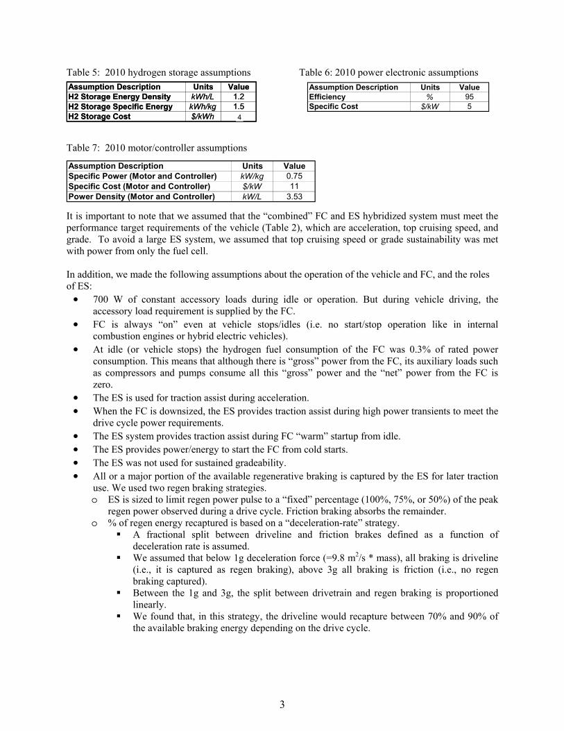
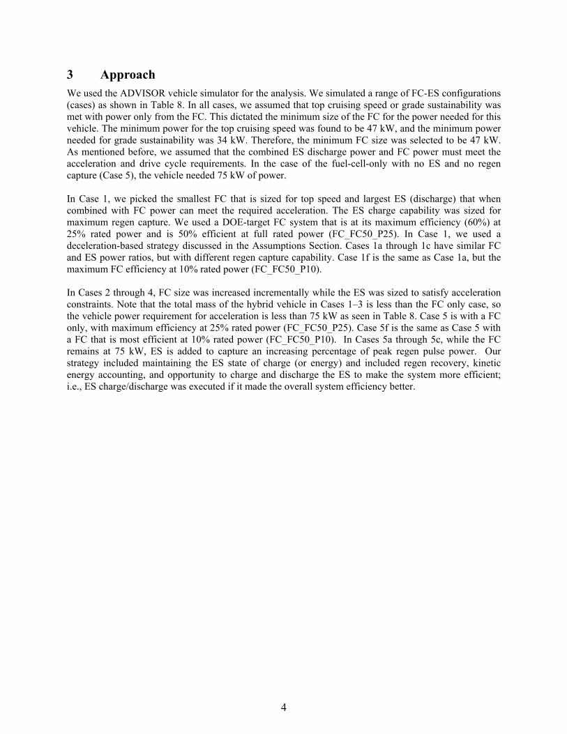
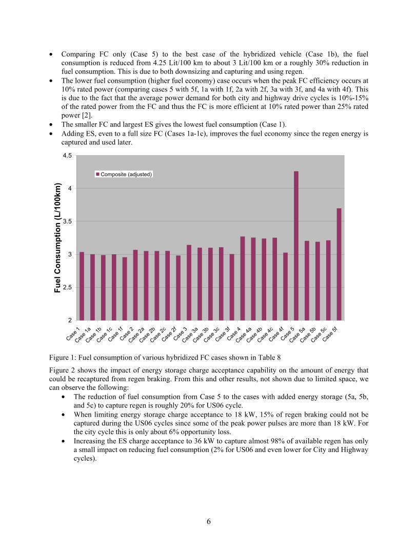
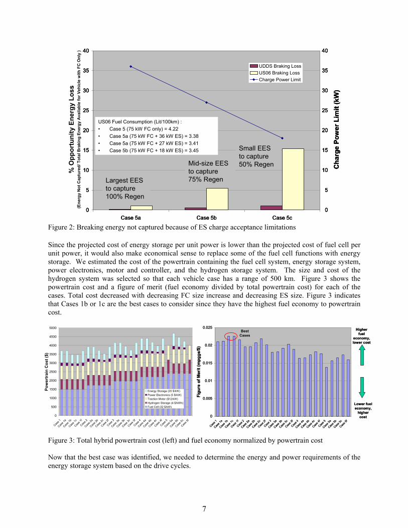
Bra
king
Los
ses
( o
f fue
l cel
l onl
y ca
se)
Pow
er (k
W)
UDDS Braking LossUS06 Braking LossCharge Power Limit
Largest EES to capture 100 Regen
Small EES to capture 50 RegenMid-size EES
to capture 75 Regen
O
ppor
tuni
ty E
nerg
y Lo
ss(E
nerg
yN
ot C
aptu
red
Tota
lBra
king
Ene
rgy
Ava
ilabl
e fo
r Veh
icle
with
FC
Onl
y)
US06 Fuel Consumption (Lit100km) bull Case 5 (75 kW FC only) = 422bull Case 5a (75 kW FC + 36 kW ES) = 338bull Case 5a (75 kW FC + 27 kW ES) = 341bull Case 5b (75 kW FC + 18 kW ES) = 345
Bra
king
Los
ses
( o
f fue
l cel
l onl
y ca
se)
Pow
er (k
W)
UDDS Braking LossUS06 Braking LossCharge Power Limit
Largest EES to capture 100 Regen
Small EES to capture 50 RegenMid-size EES
to capture 75 Regen
O
ppor
tuni
ty E
nerg
y Lo
ss(E
nerg
yN
ot C
aptu
red
Tota
lBra
king
Ene
rgy
Ava
ilabl
e fo
r Veh
icle
with
FC
Onl
y)
Bra
king
Los
ses
( o
f fue
l cel
l onl
y ca
se)
Pow
er (k
W)
Best Cases
4000
4500
353535 353535
0
25
30
40
Case 5a Case 5b Case 5c 0
25
30
40
0
25
30
40
Case 5a Case 5b Case 5c0
25
30
40
0
25
30
40
Case 5a Case 5b Case 5c
UDDS Braking Loss US06 Braking Loss Charge Power Limit
Largest EES to capture 100 Regen
Small EES to capture 50 RegenMid-size EES
to capture 75 Regen
0
25
30
40
US06 Fuel Consumption (Lit100km) bull Case 5 (75 kW FC only) = 422 bull Case 5a (75 kW FC + 36 kW ES) = 338 bull Case 5a (75 kW FC + 27 kW ES) = 341 bull Case 5b (75 kW FC + 18 kW ES) = 345
O
ppor
tuni
ty E
nerg
y Lo
ss
(Ene
rgy
Not
Cap
ture
d T
otal
Bra
king
Ene
rgy
Ava
ilabl
e fo
r Veh
icle
with
FC
Onl
y )
Cha
rge
Pow
er L
imit
(kW
)C
harg
e Po
wer
Lim
it (k
W)
Cha
rge
Pow
er L
imit
(kW
)
202020202020
151515 151515
101010 101010
555555
Figure 2 Breaking energy not captured because of ES charge acceptance limitations
Since the projected cost of energy storage per unit power is lower than the projected cost of fuel cell per unit power it would also make economical sense to replace some of the fuel cell functions with energystorage We estimated the cost of the powertrain containing the fuel cell system energy storage systempower electronics motor and controller and the hydrogen storage system The size and cost of the hydrogen system was selected so that each vehicle case has a range of 500 km Figure 3 shows the powertrain cost and a figure of merit (fuel economy divided by total powertrain cost) for each of the cases Total cost decreased with decreasing FC size increase and decreasing ES size Figure 3 indicates that Cases 1b or 1c are the best cases to consider since they have the highest fuel economy to powertrain cost
0
1500
2000
2500
3000
3500
Pow
ertr
ain
Cos
t ($)
Energy Storage (20 $kW) Power Electronics (5 $kW) Traction Motor ($12kW) Hydrogen Storage (4 $kWh) Fuel Cell (32 $kW)
002500255000 Best
Cases
lower costlower cost002002
00050005Lower fuelLower fuel
00
HigherHigher fuelfuel
economyeconomy
Figu
re o
f Mer
it (m
pgge
$)
Figu
re o
f Mer
it (m
pgge
$)
00150015
001001
economyeconomyhigherhigher costcost
e 1 a 1b
Case 1
ce 1
f 2 2a
2b 2c 2f e 3 a 3
Case 3
b c 3f e 4 a 4b e 4
c 4f 5 5a b
se5c 5f
11 aa bb 11cc 1f1f 22 aa
ase 2b
ase 2b 22cc 33
se3a
se3a 33bb e 3e 3
cc 3f3f 44 aa bb 44cc 4f4f 55 aa 5b5b 55cce 2e 2ff
e 5e 5ff3 4 5se se 11 11 22 44 44 55se se se se sseeas
eas
eas
eas
eas
eas
eas
eas
eeas se e e e as e e as se e e e ee ee eeas sese sese sese seseCaCasese sese sese sese sese sese sese eeCa as CaCasCas Cas Cas Cas Cas Cas Cas Cas CaCass asas CaCass CaCass CaCassCa Ca CaCa
CaCass CaCassCaa C C CaC CaCa CaCa CaCa CaCaCaCa CaCa CaCa CaCa CaCa CaCa CaCa CaCaCC CC CC CCC CCCC
Figure 3 Total hybrid powertrain cost (left) and fuel economy normalized by powertrain cost
Now that the best case was identified we needed to determine the energy and power requirements of the energy storage system based on the drive cycles
7
500
1000
C C
1
Average Pulse Power
Peak Pulse Power
42 Power Profile Analysis The major question is ldquoHow can we determine ESS requirements for meeting instantaneous power demands for a particular cyclerdquo From the analysis one must come up with the required discharge power for a specified duration required charge power for a specified duration and amount of available energy needed to support the power profile from a drive cycle We analyzed all the drive cycles previously indicated and separated the power demands of the FC and the ES For the ES power profile we overlaid all pulse power events of a driving profile on the same figure with start times set to zero The ranges of the profile shapes were varied some with sharp tall peaks and some broad with multiple small peaks in the middle To simplify the analysis to be able to extract information we assigned the duration of the events for the broad peaks and an associated average pulse power for that peak For the sharp peak portion of each segment we assigned a short duration for the pulse peak power and magnitude of the pulse peak power Figure 4 depicts this representation
Duration at Peak Power
Duration of Event
Duration atPeak Power
Duration of Event
Duration atPeak Power
Duration of Event
Average Pulse Power
Peak Pulse Power
Figure 4 Analysis of energy storage power profile (example is for Case 1 with US06)
The energy captured or needed in each peak was calculated based on the average pulse power times during the duration of the event and is called usable or available energy We then plotted the average pulse power versus the available energy for various cases Figure 5 shows such a plot for various cases
We also looked at the distribution of the energy storage system operating points for all the cycles to estimate mean median and standard deviation for the peak pulse power Peak pulse power and average pulse power were plotted versus the duration of associated event We included the required power for acceleration Figure 6 shows peak pulse and average pulse power as a function of duration for various drive cycles and acceleration It can be seen that peak power events typically only last for short durations of less than 1 second From Figures 5 and 6 we believe that we need an ES system with 25 kW discharge capability for 12 seconds and charge capability of 20 kW for 5 seconds for all the categories in Case 1 Either NiMH or Li-ion batteries could deliver such power and energy capabilities Of course other requirements such as cost cycle life calendar life operating temperature range and self-discharge rate will dictate the final selection Acceleration performance sets discharge requirements and the US06 cycle sets charge requirements We should note that for FC startups (not traction) some FC systems may need up to 10 kW of power for 15 seconds The energy requirements would be 42 Wh So the energy and power requirements for cold startup will be within the capability of the recommended energy storage The startup of the FC vehicles
8
100 regen cases
75 regen cases
50 regen cases
5
from very cold temperatures (below -10degC) with batteries may be challenging since the batteries have limited performance capabilities at low temperatures Ultracapacitors have better performance capabilities than batteries at cold temperatures so it is possible that we may select ultracapacitors over batteries for this reason even though it may not be the most desirable approach
6060R
ated
Pow
er (k
W)
Rat
ed P
ower
(kW
)
5050
4040
3030
2020
1010
0050 100 150 200 250 30050 100 150 200 250 300
100 regen cases
75 regen cases
50 regen cases
100 regen cases
75 regen cases
50 regen cases
Usable Energy Range (Wh)Usable Energy Range (Wh)
Figure 5 Power and associated energy needs for various cases studied
Figure 6 Peak pulse power (left) and average pulse power (right) versus duration for multiple cycles
Concluding Remarks We analyzed ES roles in a FC vehicle Hybridizing a FC vehicle with an ES system improves the fuel economy and reduces cost based on the 2010 DOEFreedomCAR targets for components of a hybrid FC vehicle The ES will also improve vehicle response by supplementing the FCrsquos limited transient response We described a process for determining ES requirements We found that the peak power events for most drive cycles are very brief and less than 1 second In general 25-30 improvement in fuel consumption can be achieved with hybridization As long as the majority of regen is captured regen strategy is not critical The most fuel-efficient scenario was also the least expensive scenario (smallest fuel cell with moderate ESS) Intelligent energy management strategies to utilize captured regen energy in FC hybrid vehicles are critical Fuel consumption is lower with a FC with peak efficiency of around 10 rated
9
power For the lightweight aerodynamic midsize car we proposed an energy storage system with 25 kW discharge (12 seconds) 20 kW charge (5 seconds) and available energy of 250 Wh and a 56 kW FC
We will continue working with the FreedomCAR Technical Teams to further refine the assumptions and the analysis to recommend final requirements for ES for FC hybrids Of interest is the quantification of the energy and power available from a fuel cell system to charge the energy storage during long idles or ramping down of the fuel cell from high to lower power
Acknowledgments The US Department of Energy (DOE) Office of the FreedomCAR and Vehicle Technology supported this effort We appreciate the technical guidance provided by the United States Advanced Battery Consortium and FreedomCAR Electrochemical Energy Storage Technical Team particularly Ted Miller from Ford and Cyrus Ashtiani from DaimlerChrysler
References [1] Markel et al ldquoFuel Cell Energy Storage Analysisrdquo Proceedings of Advanced Automotive Battery Conference San Francisco CA June 4-6 2004
[2] Zolot etal ldquoEnergy Storage Requirements for Hybrid Fuel Cell Vehiclesrdquo Proceedings of Advanced Automotive Battery Conference Nice France June 14-16 2003
[3] Wipke K Markel T Nelson D ldquoOptimizing Energy Management Strategy and Degree of Hybridization for a Hydrogen Fuel Cell SUVrdquo Proceedings of 18th Electric Vehicle Symposium Berlin Germany October 2001
[4] Markel T Wipke K ldquoOptimization Techniques for Hybrid Electric Vehicle Analysis Using ADVISORrdquo Proceedings of the ASME International Mechanical Engineering Congress and Exposition New York New York November 11-16 2001
[5] Yamaguchi J ldquoLeading the Way Fuel Cell Vehicles from Toyota and Honda Are Hitting the Streets for Customer Use in Both Japan and USrdquo Automotive Engineering International March 2003 pp 54-58
[6] Tamernori K Oki N Kato S and Yamamoto K ldquoApplication Studies of Electric Double Layer Capacitor System for Fuel Cell Vehiclesrdquo Third International Advanced Automotive Battery Conference Nice France June 10-13- 2003
[7] DOE- FreedomCAR and Vehicle Technologies and Hydrogen Fuel Cells amp Infrastructure Technologies Programs ldquoMulti-Year Research Development and Demonstration Planrdquo httpwwweereenergygovhydrogenandfuelcellsmypp and httpwwweereenergygovvehiclesandfuelsresourcesfcvt_myppshtml
Authors
Tony Markel Senior Engineer National Renewable Energy Laboratory 1617 Cole Blvd MS 1633 Golden CO 80401 303-275-4478 303-275-4415 tony_markelnrelgov
As part of the vehicle systems analysis team Mr Markel applies computer modeling and simulation to the evaluation of advanced automotive systems He has been instrumental in the development of the ADVISORtrade software tool His technology focus areas include advanced numerical and architectural methods for vehicle systems analysis and fuel cell systems research and
development Before joining NREL in 1996 Mr Markel worked at Argonne National Laboratory on various transportation-related projects He has a BSE in mechanical engineering with an emphasis in fluid and thermal sciences and is currently attending the University of Colorado to pursue a MS in mechanical engineering
10
Ahmad Pesaran Principal Engineer National Renewable Energy Laboratory 1617 Cole Blvd MS 1633 Golden CO 80401 303-275-4441 303-275-4415 ahmad_pesarannrelgov
Dr Pesaran joined NREL in 1983 and has been working on various energy systems such as solar cooling ocean thermal energy conversion air conditioning desiccant dehumidificationcooling for buildings and buses and most recently hybrid electric vehicles Since 1995 he has been working on hybrid electric vehicle projects He is currently the project manager for various activities related to
battery thermal characterization battery thermal analysis and battery modeling and simulations Dr Pesaran holds a BS in chemical engineering from Shiraz University as well as an MS in engineering and a PhD in mechanical engineering from UCLA He is a member of the FreedomCAR Electrochemical Energy Storage Technical Team
Matthew Zolot Research Engineer National Renewable Energy Laboratory 1617 Cole Blvd MS 1633 Golden CO 80401 303-275-4640 303-275-4415 matthew_zolotnrelgov
Matthew Zolot is a research engineer in the Center for Transportation Technologies and Systems (CTTS) at the National Renewable Energy Laboratory He is in CTTS Advanced Vehicle Systems Group supporting the energy storage and advanced power electronics teams Mr Zolot received a BS in electrical engineering from Georgia Institute of Technology and is currently working
toward an MS at the Colorado School of Mines During his engineering career he has been employed at Agilent Technologies in the test and measurement division and Lucent Technologies in the optical network division He has worked on hybrid vehicle mobile data acquisition simulation testing and analyses of hybrid vehicles and components and contributes to the development of NRELs ADVISORtrade vehicle simulator
Sam Sprik Engineer National Renewable Energy Laboratory 1617 Cole Blvd MS 1633 Golden CO 80401 303-275-4431 303-275-4415 sam_spriknrelgov
Mr Sprik works on vehicle systems analysis and the graphic user interface development of ADVISORtrade software NRELs advanced vehicle simulator software He is educated and interested in control theory virtual reality and manufacturing quality While a research assistant at the University of Michigan he measured and analyzed measurement processes at Chrysler on vehicle
body parts He is well versed in MATLABSimulink programming and in Virtual Reality Modeling Language along with some geometric modeling programs Mr Sprik holds a BS in mechanical engineering from Calvin College and an MSME from the University of Michigan
Harshad S Tataria USABC Technical Advisory Committee amp FreedomCAR Program Manager General Motors Corporation 30001 Van Dyke Avenue MC 480-210-427 Warren MI 48092 USA 586-575-3472 586-492-6645 harshadstatariagmcom
Mr Harshad Tataria is a member of both the United States Advanced Battery Consortium (USABC) Technical Advisory Committee and the FreedomCAR Electrochemical Energy Storage Technical Team He is a Staff Project Engineer at General Motors Corp where he is responsible for the
development of energy storage systems for HEVs Mr Tataria has over 30 years of experience in battery development His experience includes Lead-Acid NiMH Li metal primary and secondary and Li-Ion batteries He has obtained many patents and published many papers in various scientific journals
Tien Q Duong Office of FreedomCAR and Vehicle Technologies US Department of Energy 1000 Independence Avenue SW Washington DC 20585 USA 202-586-2210 202-586-1600 (fax) TienDuongeedoegov
Mr Duong is Vehicles Technologies Team Lead at the Department of Energyrsquos FreedomCAR and Vehicle Technologies Program Office Mr Duong received his MS degree in Civil Environmental Engineering and his BS degree in Electrical Engineering from Virginia Polytechnic Institute and
State University in Blacksburg Virginia He is a member of USABC Managing Committee
11
REPORT DOCUMENTATION PAGE Form Approved OMB No 0704-0188
The public reporting burden for this collection of information is estimated to average 1 hour per response including the time for reviewing instructions searching existing data sources gathering and maintaining the data needed and completing and reviewing the collection of information Send comments regarding this burden estimate or any other aspect of this collection of information including suggestions for reducing the burden to Department of Defense Executive Services and Communications Directorate (0704-0188) Respondents should be aware that notwithstanding any other provision of law no person shall be subject to any penalty for failing to comply with a collection of information if it does not display a currently valid OMB control number PLEASE DO NOT RETURN YOUR FORM TO THE ABOVE ORGANIZATION 1 REPORT DATE (DD-MM-YYYY)
April 2005 2 REPORT TYPE
Conference Paper 3 DATES COVERED (From - To)
4 TITLE AND SUBTITLE Energy Storage Fuel Cell Vehicle Analysis Preprint
5a CONTRACT NUMBER DE-AC36-99-GO10337
5b GRANT NUMBER
5c PROGRAM ELEMENT NUMBER
6 AUTHOR(S) T Markel A Pesaran M Zolot S Sprik H Tataria and T Duong
5d PROJECT NUMBER NRELCP-540-37567
5e TASK NUMBER FC056000
5f WORK UNIT NUMBER
7 PERFORMING ORGANIZATION NAME(S) AND ADDRESS(ES) National Renewable Energy Laboratory 1617 Cole Blvd Golden CO 80401-3393
8 PERFORMING ORGANIZATION REPORT NUMBER NRELCP-540-37567
9 SPONSORINGMONITORING AGENCY NAME(S) AND ADDRESS(ES) 10 SPONSORMONITORS ACRONYM(S) NREL
11 SPONSORINGMONITORING AGENCY REPORT NUMBER
12 DISTRIBUTION AVAILABILITY STATEMENT National Technical Information Service US Department of Commerce 5285 Port Royal Road Springfield VA 22161
13 SUPPLEMENTARY NOTES
14 ABSTRACT (Maximum 200 Words) In recent years hydrogen fuel cell (FC) vehicle technology has received considerable attention as a strategy to decrease oil consumption and reduce harmful emissions However the cost transient response and cold performance of FC systems may present significant challenges to widespread adoption of the technology for transportation in the next 15 years The objectives of this effort were to perform energy storage modeling with fuel cell vehicle simulations to quantify the benefits of hybridization and to identify a process for setting the requirements of ES for hydrogen-powered FC vehicles for US Department of Energyrsquos Energy Storage Program
15 SUBJECT TERMS hybrid energy storage fuel cell simulation HEV regenerative braking
16 SECURITY CLASSIFICATION OF 17 LIMITATION OF ABSTRACT
UL
18 NUMBER OF PAGES
19a NAME OF RESPONSIBLE PERSON
a REPORT Unclassified
b ABSTRACT Unclassified
c THIS PAGE Unclassified 19b TELEPHONE NUMBER (Include area code)
Standard Form 298 (Rev 898) Prescribed by ANSI Std Z3918
F1147-E(122004)

Average Pulse Power
Peak Pulse Power
42 Power Profile Analysis The major question is ldquoHow can we determine ESS requirements for meeting instantaneous power demands for a particular cyclerdquo From the analysis one must come up with the required discharge power for a specified duration required charge power for a specified duration and amount of available energy needed to support the power profile from a drive cycle We analyzed all the drive cycles previously indicated and separated the power demands of the FC and the ES For the ES power profile we overlaid all pulse power events of a driving profile on the same figure with start times set to zero The ranges of the profile shapes were varied some with sharp tall peaks and some broad with multiple small peaks in the middle To simplify the analysis to be able to extract information we assigned the duration of the events for the broad peaks and an associated average pulse power for that peak For the sharp peak portion of each segment we assigned a short duration for the pulse peak power and magnitude of the pulse peak power Figure 4 depicts this representation
Duration at Peak Power
Duration of Event
Duration atPeak Power
Duration of Event
Duration atPeak Power
Duration of Event
Average Pulse Power
Peak Pulse Power
Figure 4 Analysis of energy storage power profile (example is for Case 1 with US06)
The energy captured or needed in each peak was calculated based on the average pulse power times during the duration of the event and is called usable or available energy We then plotted the average pulse power versus the available energy for various cases Figure 5 shows such a plot for various cases
We also looked at the distribution of the energy storage system operating points for all the cycles to estimate mean median and standard deviation for the peak pulse power Peak pulse power and average pulse power were plotted versus the duration of associated event We included the required power for acceleration Figure 6 shows peak pulse and average pulse power as a function of duration for various drive cycles and acceleration It can be seen that peak power events typically only last for short durations of less than 1 second From Figures 5 and 6 we believe that we need an ES system with 25 kW discharge capability for 12 seconds and charge capability of 20 kW for 5 seconds for all the categories in Case 1 Either NiMH or Li-ion batteries could deliver such power and energy capabilities Of course other requirements such as cost cycle life calendar life operating temperature range and self-discharge rate will dictate the final selection Acceleration performance sets discharge requirements and the US06 cycle sets charge requirements We should note that for FC startups (not traction) some FC systems may need up to 10 kW of power for 15 seconds The energy requirements would be 42 Wh So the energy and power requirements for cold startup will be within the capability of the recommended energy storage The startup of the FC vehicles
8
100 regen cases
75 regen cases
50 regen cases
5
from very cold temperatures (below -10degC) with batteries may be challenging since the batteries have limited performance capabilities at low temperatures Ultracapacitors have better performance capabilities than batteries at cold temperatures so it is possible that we may select ultracapacitors over batteries for this reason even though it may not be the most desirable approach
6060R
ated
Pow
er (k
W)
Rat
ed P
ower
(kW
)
5050
4040
3030
2020
1010
0050 100 150 200 250 30050 100 150 200 250 300
100 regen cases
75 regen cases
50 regen cases
100 regen cases
75 regen cases
50 regen cases
Usable Energy Range (Wh)Usable Energy Range (Wh)
Figure 5 Power and associated energy needs for various cases studied
Figure 6 Peak pulse power (left) and average pulse power (right) versus duration for multiple cycles
Concluding Remarks We analyzed ES roles in a FC vehicle Hybridizing a FC vehicle with an ES system improves the fuel economy and reduces cost based on the 2010 DOEFreedomCAR targets for components of a hybrid FC vehicle The ES will also improve vehicle response by supplementing the FCrsquos limited transient response We described a process for determining ES requirements We found that the peak power events for most drive cycles are very brief and less than 1 second In general 25-30 improvement in fuel consumption can be achieved with hybridization As long as the majority of regen is captured regen strategy is not critical The most fuel-efficient scenario was also the least expensive scenario (smallest fuel cell with moderate ESS) Intelligent energy management strategies to utilize captured regen energy in FC hybrid vehicles are critical Fuel consumption is lower with a FC with peak efficiency of around 10 rated
9
power For the lightweight aerodynamic midsize car we proposed an energy storage system with 25 kW discharge (12 seconds) 20 kW charge (5 seconds) and available energy of 250 Wh and a 56 kW FC
We will continue working with the FreedomCAR Technical Teams to further refine the assumptions and the analysis to recommend final requirements for ES for FC hybrids Of interest is the quantification of the energy and power available from a fuel cell system to charge the energy storage during long idles or ramping down of the fuel cell from high to lower power
Acknowledgments The US Department of Energy (DOE) Office of the FreedomCAR and Vehicle Technology supported this effort We appreciate the technical guidance provided by the United States Advanced Battery Consortium and FreedomCAR Electrochemical Energy Storage Technical Team particularly Ted Miller from Ford and Cyrus Ashtiani from DaimlerChrysler
References [1] Markel et al ldquoFuel Cell Energy Storage Analysisrdquo Proceedings of Advanced Automotive Battery Conference San Francisco CA June 4-6 2004
[2] Zolot etal ldquoEnergy Storage Requirements for Hybrid Fuel Cell Vehiclesrdquo Proceedings of Advanced Automotive Battery Conference Nice France June 14-16 2003
[3] Wipke K Markel T Nelson D ldquoOptimizing Energy Management Strategy and Degree of Hybridization for a Hydrogen Fuel Cell SUVrdquo Proceedings of 18th Electric Vehicle Symposium Berlin Germany October 2001
[4] Markel T Wipke K ldquoOptimization Techniques for Hybrid Electric Vehicle Analysis Using ADVISORrdquo Proceedings of the ASME International Mechanical Engineering Congress and Exposition New York New York November 11-16 2001
[5] Yamaguchi J ldquoLeading the Way Fuel Cell Vehicles from Toyota and Honda Are Hitting the Streets for Customer Use in Both Japan and USrdquo Automotive Engineering International March 2003 pp 54-58
[6] Tamernori K Oki N Kato S and Yamamoto K ldquoApplication Studies of Electric Double Layer Capacitor System for Fuel Cell Vehiclesrdquo Third International Advanced Automotive Battery Conference Nice France June 10-13- 2003
[7] DOE- FreedomCAR and Vehicle Technologies and Hydrogen Fuel Cells amp Infrastructure Technologies Programs ldquoMulti-Year Research Development and Demonstration Planrdquo httpwwweereenergygovhydrogenandfuelcellsmypp and httpwwweereenergygovvehiclesandfuelsresourcesfcvt_myppshtml
Authors
Tony Markel Senior Engineer National Renewable Energy Laboratory 1617 Cole Blvd MS 1633 Golden CO 80401 303-275-4478 303-275-4415 tony_markelnrelgov
As part of the vehicle systems analysis team Mr Markel applies computer modeling and simulation to the evaluation of advanced automotive systems He has been instrumental in the development of the ADVISORtrade software tool His technology focus areas include advanced numerical and architectural methods for vehicle systems analysis and fuel cell systems research and
development Before joining NREL in 1996 Mr Markel worked at Argonne National Laboratory on various transportation-related projects He has a BSE in mechanical engineering with an emphasis in fluid and thermal sciences and is currently attending the University of Colorado to pursue a MS in mechanical engineering
10
Ahmad Pesaran Principal Engineer National Renewable Energy Laboratory 1617 Cole Blvd MS 1633 Golden CO 80401 303-275-4441 303-275-4415 ahmad_pesarannrelgov
Dr Pesaran joined NREL in 1983 and has been working on various energy systems such as solar cooling ocean thermal energy conversion air conditioning desiccant dehumidificationcooling for buildings and buses and most recently hybrid electric vehicles Since 1995 he has been working on hybrid electric vehicle projects He is currently the project manager for various activities related to
battery thermal characterization battery thermal analysis and battery modeling and simulations Dr Pesaran holds a BS in chemical engineering from Shiraz University as well as an MS in engineering and a PhD in mechanical engineering from UCLA He is a member of the FreedomCAR Electrochemical Energy Storage Technical Team
Matthew Zolot Research Engineer National Renewable Energy Laboratory 1617 Cole Blvd MS 1633 Golden CO 80401 303-275-4640 303-275-4415 matthew_zolotnrelgov
Matthew Zolot is a research engineer in the Center for Transportation Technologies and Systems (CTTS) at the National Renewable Energy Laboratory He is in CTTS Advanced Vehicle Systems Group supporting the energy storage and advanced power electronics teams Mr Zolot received a BS in electrical engineering from Georgia Institute of Technology and is currently working
toward an MS at the Colorado School of Mines During his engineering career he has been employed at Agilent Technologies in the test and measurement division and Lucent Technologies in the optical network division He has worked on hybrid vehicle mobile data acquisition simulation testing and analyses of hybrid vehicles and components and contributes to the development of NRELs ADVISORtrade vehicle simulator
Sam Sprik Engineer National Renewable Energy Laboratory 1617 Cole Blvd MS 1633 Golden CO 80401 303-275-4431 303-275-4415 sam_spriknrelgov
Mr Sprik works on vehicle systems analysis and the graphic user interface development of ADVISORtrade software NRELs advanced vehicle simulator software He is educated and interested in control theory virtual reality and manufacturing quality While a research assistant at the University of Michigan he measured and analyzed measurement processes at Chrysler on vehicle
body parts He is well versed in MATLABSimulink programming and in Virtual Reality Modeling Language along with some geometric modeling programs Mr Sprik holds a BS in mechanical engineering from Calvin College and an MSME from the University of Michigan
Harshad S Tataria USABC Technical Advisory Committee amp FreedomCAR Program Manager General Motors Corporation 30001 Van Dyke Avenue MC 480-210-427 Warren MI 48092 USA 586-575-3472 586-492-6645 harshadstatariagmcom
Mr Harshad Tataria is a member of both the United States Advanced Battery Consortium (USABC) Technical Advisory Committee and the FreedomCAR Electrochemical Energy Storage Technical Team He is a Staff Project Engineer at General Motors Corp where he is responsible for the
development of energy storage systems for HEVs Mr Tataria has over 30 years of experience in battery development His experience includes Lead-Acid NiMH Li metal primary and secondary and Li-Ion batteries He has obtained many patents and published many papers in various scientific journals
Tien Q Duong Office of FreedomCAR and Vehicle Technologies US Department of Energy 1000 Independence Avenue SW Washington DC 20585 USA 202-586-2210 202-586-1600 (fax) TienDuongeedoegov
Mr Duong is Vehicles Technologies Team Lead at the Department of Energyrsquos FreedomCAR and Vehicle Technologies Program Office Mr Duong received his MS degree in Civil Environmental Engineering and his BS degree in Electrical Engineering from Virginia Polytechnic Institute and
State University in Blacksburg Virginia He is a member of USABC Managing Committee
11
REPORT DOCUMENTATION PAGE Form Approved OMB No 0704-0188
The public reporting burden for this collection of information is estimated to average 1 hour per response including the time for reviewing instructions searching existing data sources gathering and maintaining the data needed and completing and reviewing the collection of information Send comments regarding this burden estimate or any other aspect of this collection of information including suggestions for reducing the burden to Department of Defense Executive Services and Communications Directorate (0704-0188) Respondents should be aware that notwithstanding any other provision of law no person shall be subject to any penalty for failing to comply with a collection of information if it does not display a currently valid OMB control number PLEASE DO NOT RETURN YOUR FORM TO THE ABOVE ORGANIZATION 1 REPORT DATE (DD-MM-YYYY)
April 2005 2 REPORT TYPE
Conference Paper 3 DATES COVERED (From - To)
4 TITLE AND SUBTITLE Energy Storage Fuel Cell Vehicle Analysis Preprint
5a CONTRACT NUMBER DE-AC36-99-GO10337
5b GRANT NUMBER
5c PROGRAM ELEMENT NUMBER
6 AUTHOR(S) T Markel A Pesaran M Zolot S Sprik H Tataria and T Duong
5d PROJECT NUMBER NRELCP-540-37567
5e TASK NUMBER FC056000
5f WORK UNIT NUMBER
7 PERFORMING ORGANIZATION NAME(S) AND ADDRESS(ES) National Renewable Energy Laboratory 1617 Cole Blvd Golden CO 80401-3393
8 PERFORMING ORGANIZATION REPORT NUMBER NRELCP-540-37567
9 SPONSORINGMONITORING AGENCY NAME(S) AND ADDRESS(ES) 10 SPONSORMONITORS ACRONYM(S) NREL
11 SPONSORINGMONITORING AGENCY REPORT NUMBER
12 DISTRIBUTION AVAILABILITY STATEMENT National Technical Information Service US Department of Commerce 5285 Port Royal Road Springfield VA 22161
13 SUPPLEMENTARY NOTES
14 ABSTRACT (Maximum 200 Words) In recent years hydrogen fuel cell (FC) vehicle technology has received considerable attention as a strategy to decrease oil consumption and reduce harmful emissions However the cost transient response and cold performance of FC systems may present significant challenges to widespread adoption of the technology for transportation in the next 15 years The objectives of this effort were to perform energy storage modeling with fuel cell vehicle simulations to quantify the benefits of hybridization and to identify a process for setting the requirements of ES for hydrogen-powered FC vehicles for US Department of Energyrsquos Energy Storage Program
15 SUBJECT TERMS hybrid energy storage fuel cell simulation HEV regenerative braking
16 SECURITY CLASSIFICATION OF 17 LIMITATION OF ABSTRACT
UL
18 NUMBER OF PAGES
19a NAME OF RESPONSIBLE PERSON
a REPORT Unclassified
b ABSTRACT Unclassified
c THIS PAGE Unclassified 19b TELEPHONE NUMBER (Include area code)
Standard Form 298 (Rev 898) Prescribed by ANSI Std Z3918
F1147-E(122004)

100 regen cases
75 regen cases
50 regen cases
5
from very cold temperatures (below -10degC) with batteries may be challenging since the batteries have limited performance capabilities at low temperatures Ultracapacitors have better performance capabilities than batteries at cold temperatures so it is possible that we may select ultracapacitors over batteries for this reason even though it may not be the most desirable approach
6060R
ated
Pow
er (k
W)
Rat
ed P
ower
(kW
)
5050
4040
3030
2020
1010
0050 100 150 200 250 30050 100 150 200 250 300
100 regen cases
75 regen cases
50 regen cases
100 regen cases
75 regen cases
50 regen cases
Usable Energy Range (Wh)Usable Energy Range (Wh)
Figure 5 Power and associated energy needs for various cases studied
Figure 6 Peak pulse power (left) and average pulse power (right) versus duration for multiple cycles
Concluding Remarks We analyzed ES roles in a FC vehicle Hybridizing a FC vehicle with an ES system improves the fuel economy and reduces cost based on the 2010 DOEFreedomCAR targets for components of a hybrid FC vehicle The ES will also improve vehicle response by supplementing the FCrsquos limited transient response We described a process for determining ES requirements We found that the peak power events for most drive cycles are very brief and less than 1 second In general 25-30 improvement in fuel consumption can be achieved with hybridization As long as the majority of regen is captured regen strategy is not critical The most fuel-efficient scenario was also the least expensive scenario (smallest fuel cell with moderate ESS) Intelligent energy management strategies to utilize captured regen energy in FC hybrid vehicles are critical Fuel consumption is lower with a FC with peak efficiency of around 10 rated
9
power For the lightweight aerodynamic midsize car we proposed an energy storage system with 25 kW discharge (12 seconds) 20 kW charge (5 seconds) and available energy of 250 Wh and a 56 kW FC
We will continue working with the FreedomCAR Technical Teams to further refine the assumptions and the analysis to recommend final requirements for ES for FC hybrids Of interest is the quantification of the energy and power available from a fuel cell system to charge the energy storage during long idles or ramping down of the fuel cell from high to lower power
Acknowledgments The US Department of Energy (DOE) Office of the FreedomCAR and Vehicle Technology supported this effort We appreciate the technical guidance provided by the United States Advanced Battery Consortium and FreedomCAR Electrochemical Energy Storage Technical Team particularly Ted Miller from Ford and Cyrus Ashtiani from DaimlerChrysler
References [1] Markel et al ldquoFuel Cell Energy Storage Analysisrdquo Proceedings of Advanced Automotive Battery Conference San Francisco CA June 4-6 2004
[2] Zolot etal ldquoEnergy Storage Requirements for Hybrid Fuel Cell Vehiclesrdquo Proceedings of Advanced Automotive Battery Conference Nice France June 14-16 2003
[3] Wipke K Markel T Nelson D ldquoOptimizing Energy Management Strategy and Degree of Hybridization for a Hydrogen Fuel Cell SUVrdquo Proceedings of 18th Electric Vehicle Symposium Berlin Germany October 2001
[4] Markel T Wipke K ldquoOptimization Techniques for Hybrid Electric Vehicle Analysis Using ADVISORrdquo Proceedings of the ASME International Mechanical Engineering Congress and Exposition New York New York November 11-16 2001
[5] Yamaguchi J ldquoLeading the Way Fuel Cell Vehicles from Toyota and Honda Are Hitting the Streets for Customer Use in Both Japan and USrdquo Automotive Engineering International March 2003 pp 54-58
[6] Tamernori K Oki N Kato S and Yamamoto K ldquoApplication Studies of Electric Double Layer Capacitor System for Fuel Cell Vehiclesrdquo Third International Advanced Automotive Battery Conference Nice France June 10-13- 2003
[7] DOE- FreedomCAR and Vehicle Technologies and Hydrogen Fuel Cells amp Infrastructure Technologies Programs ldquoMulti-Year Research Development and Demonstration Planrdquo httpwwweereenergygovhydrogenandfuelcellsmypp and httpwwweereenergygovvehiclesandfuelsresourcesfcvt_myppshtml
Authors
Tony Markel Senior Engineer National Renewable Energy Laboratory 1617 Cole Blvd MS 1633 Golden CO 80401 303-275-4478 303-275-4415 tony_markelnrelgov
As part of the vehicle systems analysis team Mr Markel applies computer modeling and simulation to the evaluation of advanced automotive systems He has been instrumental in the development of the ADVISORtrade software tool His technology focus areas include advanced numerical and architectural methods for vehicle systems analysis and fuel cell systems research and
development Before joining NREL in 1996 Mr Markel worked at Argonne National Laboratory on various transportation-related projects He has a BSE in mechanical engineering with an emphasis in fluid and thermal sciences and is currently attending the University of Colorado to pursue a MS in mechanical engineering
10
Ahmad Pesaran Principal Engineer National Renewable Energy Laboratory 1617 Cole Blvd MS 1633 Golden CO 80401 303-275-4441 303-275-4415 ahmad_pesarannrelgov
Dr Pesaran joined NREL in 1983 and has been working on various energy systems such as solar cooling ocean thermal energy conversion air conditioning desiccant dehumidificationcooling for buildings and buses and most recently hybrid electric vehicles Since 1995 he has been working on hybrid electric vehicle projects He is currently the project manager for various activities related to
battery thermal characterization battery thermal analysis and battery modeling and simulations Dr Pesaran holds a BS in chemical engineering from Shiraz University as well as an MS in engineering and a PhD in mechanical engineering from UCLA He is a member of the FreedomCAR Electrochemical Energy Storage Technical Team
Matthew Zolot Research Engineer National Renewable Energy Laboratory 1617 Cole Blvd MS 1633 Golden CO 80401 303-275-4640 303-275-4415 matthew_zolotnrelgov
Matthew Zolot is a research engineer in the Center for Transportation Technologies and Systems (CTTS) at the National Renewable Energy Laboratory He is in CTTS Advanced Vehicle Systems Group supporting the energy storage and advanced power electronics teams Mr Zolot received a BS in electrical engineering from Georgia Institute of Technology and is currently working
toward an MS at the Colorado School of Mines During his engineering career he has been employed at Agilent Technologies in the test and measurement division and Lucent Technologies in the optical network division He has worked on hybrid vehicle mobile data acquisition simulation testing and analyses of hybrid vehicles and components and contributes to the development of NRELs ADVISORtrade vehicle simulator
Sam Sprik Engineer National Renewable Energy Laboratory 1617 Cole Blvd MS 1633 Golden CO 80401 303-275-4431 303-275-4415 sam_spriknrelgov
Mr Sprik works on vehicle systems analysis and the graphic user interface development of ADVISORtrade software NRELs advanced vehicle simulator software He is educated and interested in control theory virtual reality and manufacturing quality While a research assistant at the University of Michigan he measured and analyzed measurement processes at Chrysler on vehicle
body parts He is well versed in MATLABSimulink programming and in Virtual Reality Modeling Language along with some geometric modeling programs Mr Sprik holds a BS in mechanical engineering from Calvin College and an MSME from the University of Michigan
Harshad S Tataria USABC Technical Advisory Committee amp FreedomCAR Program Manager General Motors Corporation 30001 Van Dyke Avenue MC 480-210-427 Warren MI 48092 USA 586-575-3472 586-492-6645 harshadstatariagmcom
Mr Harshad Tataria is a member of both the United States Advanced Battery Consortium (USABC) Technical Advisory Committee and the FreedomCAR Electrochemical Energy Storage Technical Team He is a Staff Project Engineer at General Motors Corp where he is responsible for the
development of energy storage systems for HEVs Mr Tataria has over 30 years of experience in battery development His experience includes Lead-Acid NiMH Li metal primary and secondary and Li-Ion batteries He has obtained many patents and published many papers in various scientific journals
Tien Q Duong Office of FreedomCAR and Vehicle Technologies US Department of Energy 1000 Independence Avenue SW Washington DC 20585 USA 202-586-2210 202-586-1600 (fax) TienDuongeedoegov
Mr Duong is Vehicles Technologies Team Lead at the Department of Energyrsquos FreedomCAR and Vehicle Technologies Program Office Mr Duong received his MS degree in Civil Environmental Engineering and his BS degree in Electrical Engineering from Virginia Polytechnic Institute and
State University in Blacksburg Virginia He is a member of USABC Managing Committee
11
REPORT DOCUMENTATION PAGE Form Approved OMB No 0704-0188
The public reporting burden for this collection of information is estimated to average 1 hour per response including the time for reviewing instructions searching existing data sources gathering and maintaining the data needed and completing and reviewing the collection of information Send comments regarding this burden estimate or any other aspect of this collection of information including suggestions for reducing the burden to Department of Defense Executive Services and Communications Directorate (0704-0188) Respondents should be aware that notwithstanding any other provision of law no person shall be subject to any penalty for failing to comply with a collection of information if it does not display a currently valid OMB control number PLEASE DO NOT RETURN YOUR FORM TO THE ABOVE ORGANIZATION 1 REPORT DATE (DD-MM-YYYY)
April 2005 2 REPORT TYPE
Conference Paper 3 DATES COVERED (From - To)
4 TITLE AND SUBTITLE Energy Storage Fuel Cell Vehicle Analysis Preprint
5a CONTRACT NUMBER DE-AC36-99-GO10337
5b GRANT NUMBER
5c PROGRAM ELEMENT NUMBER
6 AUTHOR(S) T Markel A Pesaran M Zolot S Sprik H Tataria and T Duong
5d PROJECT NUMBER NRELCP-540-37567
5e TASK NUMBER FC056000
5f WORK UNIT NUMBER
7 PERFORMING ORGANIZATION NAME(S) AND ADDRESS(ES) National Renewable Energy Laboratory 1617 Cole Blvd Golden CO 80401-3393
8 PERFORMING ORGANIZATION REPORT NUMBER NRELCP-540-37567
9 SPONSORINGMONITORING AGENCY NAME(S) AND ADDRESS(ES) 10 SPONSORMONITORS ACRONYM(S) NREL
11 SPONSORINGMONITORING AGENCY REPORT NUMBER
12 DISTRIBUTION AVAILABILITY STATEMENT National Technical Information Service US Department of Commerce 5285 Port Royal Road Springfield VA 22161
13 SUPPLEMENTARY NOTES
14 ABSTRACT (Maximum 200 Words) In recent years hydrogen fuel cell (FC) vehicle technology has received considerable attention as a strategy to decrease oil consumption and reduce harmful emissions However the cost transient response and cold performance of FC systems may present significant challenges to widespread adoption of the technology for transportation in the next 15 years The objectives of this effort were to perform energy storage modeling with fuel cell vehicle simulations to quantify the benefits of hybridization and to identify a process for setting the requirements of ES for hydrogen-powered FC vehicles for US Department of Energyrsquos Energy Storage Program
15 SUBJECT TERMS hybrid energy storage fuel cell simulation HEV regenerative braking
16 SECURITY CLASSIFICATION OF 17 LIMITATION OF ABSTRACT
UL
18 NUMBER OF PAGES
19a NAME OF RESPONSIBLE PERSON
a REPORT Unclassified
b ABSTRACT Unclassified
c THIS PAGE Unclassified 19b TELEPHONE NUMBER (Include area code)
Standard Form 298 (Rev 898) Prescribed by ANSI Std Z3918
F1147-E(122004)
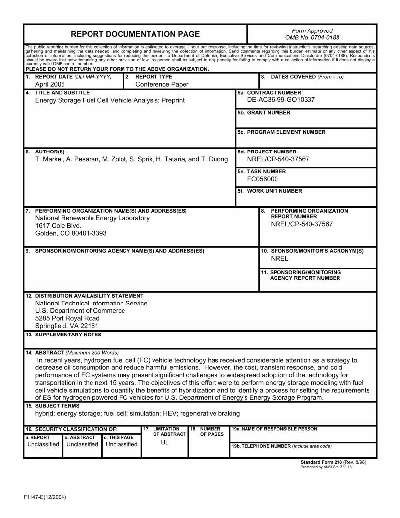