federal highway - traffix devices · federal highway administration june 15, 2017 in reply refer...
TRANSCRIPT

U.S. Deportment 1200 New Jersey Ave., SE of Transportation Washington , D.C. 20590
Federal Highway Administration
June 15, 2017 In Reply Refer To:
HSST-l/CC-132
Mr. Felipe Almanza
TrafFix Devices Inc.
160 A venida La Pata
San Clemente, CA 92673
Dear Mr. Almanza:
This letter is in response to your January 10, 2017 request for the Federal Highway
Administration (FHW A) lo review a roadside safely device, hardware, or system for eligibility
for reimbursement under the Federal-aid highway program. This FHW A letter of eligibility is
assigned FHW A control number CC-132 and is valid until a subsequent letter is issued by セ@
FHW A that expressly references this device.
Decision
the following devices are eligible, with details provided in the form which is attached as an
integral part of this letter:
• Scorpion II
Scope of this Letter
To be found eligible for Federal-aid funding, new roadside safety devices should meet the crash
test and evaluation criteria contained in the American Association of State Highway and
Transportation Officials ' (AASHTO) Manual for Assessing Safety Hardware (MASH).
However, the FHWA, the Department of Transportation, and the United States Government do
not regulate the manufacture of roadside safety devices. Eligibility for reimbursement under the
Federal-aid highway program does not establish approval, certification or endorsement of the
device for any particular purpose or use.
This letter is not a determination by the FHW A, the Department of Transportation, or the United
States Government that a vehicle crash involving the device will result in any particular
outcome, nor is it a guarantee of the in-service performance of this device. Proper
manufacturing, installation, and maintenance are required in order for this device to function as
tested.
This finding of eligibility is limited to the crashworthiness of the system and does not cover other
structural features, nor conformity with the Manual on Uniform Traffic Control Devices.

2
Eligibility for Reimbursement
Based solely on a review of crash test results and certifications submitted by the manufacturer,
and the crash test laboratory, FHWA agrees that the device described herein meets the crash test
and evaluation criteria of the AASHTO' s MASH. Therefore, the device is eligible for
reimbursement under the Federal-aid highway program if installed under the range of tested
conditions.
Name of system: Scorpion II
Type of system: Truck-Trailer Mounted Attenuator (TTMA)
Test Level: MASH Test Level 3 (TL3)
Testing conducted by: KARCO
Date ofrequest: January 13, 2017
FHW A concurs with the recommendation of the accredited crash testing laboratory as stated
within the attached form.
Full Description of the Eligible Device
The device and supporting documentation, including reports of the crash tests or other testing
done, videos of any crash testing, and/or drawings of the device, are described in the attached
form.
Notice
This eligibility letter is issued for the subject device as tested. Modifications made to the device
are not covered by this letter and will need to be tested in accordance with all recommended tests
in AASHTO's MASH as part of a new and separate submittal.
You are expected to supply potential users with sufficient information on design, installation and
maintenance requirements to ensure proper performance.
You are expected to certify to potential users that the hardware furnished has the same chemistry,
mechanical properties, and geometry as that submitted for review, and that it will meet the test
and evaluation criteria of AASHTO' s MASH.
Issuance of this letter does not convey property rights of any sort or any exclusive privilege. This
letter is based on the premise that information and reports submitted by you are accurate and
correct. We reserve the right to modify or revoke this letter if: (1) there are any inaccuracies in
the information submitted in support of your request for this letter, (2) the qualification testing
was flawed, (3) in-service performance or other information reveals safety problems, ( 4) the
system is significantly different from the version that was crash tested, or (5) any other
information indicates that the letter was issued in error or otherwise does not reflect full and
complete information about the crash worthiness of the system.

3
Standard Provisions
• To prevent misunderstanding by others, this letter of eligibility designated as FHW A
control number CC-132 shall not be reproduced except in full. This letter and the test
documentation upon which it is based are public information. All such letters and
documentation may be reviewed upon request.
• This letter shall not be construed as authorization or consent by the FHW A to use,
manufacture, or sell any patented system for which the applicant is not the patent holder.
• If the subject device is a patented product it may be considered to be proprietary. If
proprietary systems are specified by a highway agency for use on Federal-aid projects:
(a) they must be supplied through competitive bidding with equally suitable unpatented
items; (b) the highway agency must certify that they are essential for synchronization
with the existing highway facilities or that no equally suitable alternative exists; or ( c)
they must be used for research or for a distinctive type of construction on relatively short
sections of road for experimental purposes. Our regulations concerning proprietary
products are contained in Title 23 , Code of Federal Regulations, Section 635.411.
Sincerely,
Robert Ritter
Acting Director, Office of Safety
Technologies
Office of Safety
Enclosures

Version 10.0 (05/16)
Page 1 of 7
Request for Federal Aid Reimbursement Eligibility
of Highway Safety Hardware
Date of Request:
Name:
1-10-17
Felipe Almanza
I r. New (' Resubmission
... Cll........ ·e .0 ::I II)
Company:
Address:
Country:
TrafFix Devices Inc
160 Avenida La Pata San Clemente
United States
To: Michael S. Griffith, Director
FHWA, Office of Safety Technologies
I request the following devices be considered el igible for reimbursement under the Federal-aid
highway program.
Device &Testing Criterion - Enter from right to left starting with Test Level I ' -' -' I System Type
'CC': Truck-Mounted
Attenuators (TMA)
Submission Type
(e' Physical Crash Testing
(' Engineering Analysis
Device Name I Va riant Testing Criterion
AASHTOMASH
Scorpion II
Test
Level
TL3
By submitting this request for review and evaluation by the Federal Highway Administration, I certify
that the product(s) was (were) tested in conformity with the AASHTO Manual for Assessing Safety
Hardware and that the evaluation results meet the appropriate evaluation criteria in the MASH .
Individual or Organization responsible for the product:
Contact Name: Felipe Almanza Same as Submitter r8J
Company Name: TrafFix Devices Inc Same as Submitter r8J
Address: 160 Avenida La Pata San Clemente Same as Submitter r8J
Country: United States Same as Submitter r8J Enter below all disclosures of financial interests as required by the FHWA ' Federal-Aid Reimbursement
Eligibility Process for Safety Hardware Devices' document.
TrafFix Devices Inc. and Karco Engineering LLC share no financial interests between the two organizations. This
includes no shared financial interest but not limited to:
i. Compensation included wages, salaries, commissions, professional fees, or fees for business referrals
iii. Research funding or other forms of research support;
iv. Patents, copyrights, licenses, and other intellectual property interests;
vi. Business ownership and investment interests;

Version 10.0 (05/16)
Page 2 of 7
PRODUCT DESCRIPTION
(i' New Hardware or (' Modification to
• Significant Modification Existing Hardware
The Scorpion Truck Mounted Attenuator (TMA) is a mobile crash cushion attached to the rear of a support
vehicle's frame. The TMA may be used on shadow, stationary block vehicle, or on advanced warning vehicles
upstream of a moving or stationary operation. The Scorpion TMA can be used on support vehicles with a min.
actual/ curb weight of 15,000 lbs with no upper weight limit (infinite weight). Lighting consists of LED or
incandescent brake, directional, and running lights meeting FMVSS requirements and optional strobe/flashing
lights can be accommodated for enhancement of advanced warning to drivers. The structural mounting
system incorporates extender frames to provide clearance for support vehicles with excess bed overhang and
to provide clearance of equipment on the back of a support vehicle when the TMA is in the stored position. The
Scorpion TL-3 TMA has overall dimensions of 12.94 ft. (3.9 m) X 8.0 ft (2.4 m) X 2.0 ft (0.6 m) and has a ground
clearance of 12 in± 1 in (305 mm ± 25.4 mm) when deployed in the horizontal operating position. The
Scorpion TMA consists of three main components: Strut, Cartridge, and backup/diaphragm frames. The Strut
and Cartridge are the energy attenuation components. The Strut is positioned nearest to the support vehicle
and the Cartridge is positioned furthest away from the support vehicle. The Cartridge is typically the first
component impacted by an errant vehicle. The Strut consists of four outboard convex aluminum tubes (two on
each side) forming an aluminum structural weldment. The aluminum structural weldments bolt to a structural
steel diaphragm/backup frame. The structural assembly encompasses the aluminum crush Module D. The
module is made from an aluminum outer skin that contains expanded aluminum honeycomb and has overall
dimensions of 4.0 ft (1.2 m) X 6.7 ft (2.0 m) X 1.9 ft (0.6 m). Module Dis designed to accommodate an
assortment of rear facing reflective sheeting colors and patterns. The complete Strut consists of two aluminum
tube weldments, diaphragm/backup, and one Module D and has overall dimensions of 5.2 ft (1 .6 m) X 8.0 ft (2.4
m) X 2.2 ft (0.7 m). The Cartridge consists of four outboard convex aluminum tubes (two on each side) forming
an aluminum structural weldment. The aluminum structural weldments bolt to a set of steel structural
diaphragm frames. The structural assembly encompasses the two-aluminum crush Modules C. Attached to the
rear most end of the Cartridge, is the single crush Module A. Crush Modules A and Care made from an
aluminum outer skin that contains expanded aluminum honeycomb. Module A has overall dimension of 1.0 ft
(0.3 m) X 5.0 ft (1 .5 m) X 2.0 ft (0.6 m) and Module Chas overall dimension of 2 ft (0.6 m) X 5 ft (1.594 m) X 2 ft
(0.6 m). Module A is designed to accommodate an assortment of rear facing reflective sheeting colors and
patterns. The complete Cartridge consists of two aluminum tube weldments, diaphragm's, one Module A, and
two Module C and has overall dimensions of 7.71 (2.3 m) X 8 ft (2.4 m) X 2.2 ft (0.7 m). The steel diaphragm/
backup frames are are made from structural steel angles, plates, and channels that are welded into the backup
and diaphragm components and are the supporting frame members for the aluminum tubes and crush
modules. For Test 3-51 the lower Module A mounting angle was 4" (102 mm) X 4" (102 mm) and for Tests 3-50,
3-52, and 3-53 the lower Module A mounting angle is 4" (102 mm) X 6" (152 mm). The Scorpion TMA is rotated
into the stored and deployed positions by means of an on board hydraulic system. The Scorpion TMA can be
rotated in double 90° fold position over the support vehicles bed or in a single 90° fold in a vertical stored
position. An optional hydraulic powered vertical lift can be util ized with the TMA to deploy a display panel
when the TMA is lowered into the deployed position. The vertical lift is powered by the same on board
hydraulic system that rotates the TMA into the stored and deployed position. The vertical lift is sequenced to
raise and lower a panel for displaying advanced messages, directional indicators, or other notifications ..
CRASH TESTING
By signature below, the Engineer affiliated with the testing laboratory, agrees in support of this submission that
all of the critical and relevant crash tests for this device listed above were conducted to meet the MASH test
criteria. The Engineer has determined that no other crash tests are necessary to determine the device meets
the MASH criteria.
Engineer Name: Balbino A. Beltran
Engineer Signature: Balbino A. Beltran Digitally signed by Balbino A. Beltran
ON: cn=Ba lbino A. Beltran, o:KARCO Engineering, LLC., ou,
[email protected], c=US
Date: 20 17.01.13 16:35:04 -08'00'
Address: 9270 Holly Road, Adelanto, CA. 92301 Same as Submitter D Country: United States Same as Submitter D

Version 10.0 (05/16)
Page 3 of 7
A brief description of each crash test and its result:
Required Test
Number
Narrative
Description
Evaluation
Results
3-50 (1 lOOC)
The TMA was positioned in line with the test
vehicle's centerline. The inl ine centered
position examines the TMA's energy
dissipation capacity, structural adequacy,
occupant risk, with a rigidly blocked
support vehicle for no upper support
vehicle weight limit (infinite weight) . The
test was conducted using a commercially
available 2013 Kia Rio 4-door sedan with
test inertial mass of 2,431 .17 lbs ( 1, 103.0 kg).
The vehicle was in good condition, was free
of major body damage, and was not missing
any structural components. The bumpers
were standard equipment and were not
modified for this test. Based on CarFax
reporting there was no recorded history of
major accidents, was not a salvage titled
vehicle, not involved in flooding, or fire.
The test vehicle impacted the TMA at a
velocity of 60.83 mph (97.90 km/ hr) and at
an impact angle of 0.6°.
The vehicle made initial contact with the
rear Cartridge crushing Module A upon
impact and the outboard convex tube
weldments began to collapse. After the
convex tube weldments fully collapsed the
two inboard Cartridge Modules C contacted
each other and were crushed. The front
Strut sustained moderate collapse of the
outboard convex tube weldments and
minimal crush of Module D.
The impacting vehicle was brought to a
controlled stop and remained upright
throughout the impact event. The test
vehicles occupant compartment was not
penetrated and there was no measurable in
cab deformation beyond the maximum
allowable limits. The maximum roll and
pitch did not exceed 75°and occupant risk
values are within limits per MASH
specifications for Occupant Impact Velocity
and Ridedown Acceleration.
PASS

Version 10.0 (05/16)
Page 4 of 7
Required Test
Number
3-51 (2270P)
Narrative
Description
The TMA was positioned in line with the test
vehicle's centerline. The inline centered
position examines the TMA'S energy
dissipation capacity, structural adequacy,
occupant risk, with a rigidly blocked
support vehicle for no upper support
vehicle weight limit (infinite weight) . The
test was conducted using a commercially
available 2012 RAM 1500 4-door pickup
truck with test inertial mass of 4920.6 lbs
(2232.0 kg). The vehicle was in good
condition, was free of major body damage,
and was not missing any structural
components. The bumpers were standard
equipment and were not modified for this
test. Based on CarFax reporting there was
no recorded history of major accidents, was
not a salvage titled vehicle, not involved in
flooding, or fire. The test vehicle impacted
the TMA at a velocity of 63.16 mph (101 .65
km/ hr) and at an impact angle of 0.9°.
The vehicle made initial contact with the
rear Cartridge crushing Module A upon
impact and the outboard convex tube PASS
weldments began to collapse. After the
convex tube weldments fully collapsed the
two inboard Cartridge Modules C contacted
each other and were crushed. The front
Strut sets of outboard convex tube
weldments fully collapsed and the inner
Module D crushed to a near flattened state.
The TMA system contained the hydraulic
powered vertical lift to raise and lower a
display panel. The display panel and lift
system did not pose or show potential to be
a hazard in the impact event.
The impacting vehicle was brought to a
controlled stop and remained upright
throughout the impact event. The test
vehicles occupant compartment was not
penetrated and there was no measurable in
cab deformation beyond the maximum
allowable limits. The maximum roll and
pitch did not exceed 75°and occupant risk
values are within limits per MASH
specifications for Occupant Impact Velocity
and Ridedown Acceleration.
Evaluation
Results

Version 10.0 (05/16)
Page 5 of 7
3-52 (2270P)
The TMA was positioned offset 1 /3 of the
test vehicles width to the centerline of the
test vehicle. The offset position examines
the capability of a TMA to safely attenuate
off-center impacts, the TMA's structural
adequacy, occupant risk, with a rigidly
blocked support vehicle for no upper
support vehicle weight limit (infinite
weight). The test was conducted using a
commercially available 2012 RAM 1500 4
door pickup truck with test inertial mass of
4993.4 lbs (2265.0 kg). The vehicle was in
good condition, was free of major body
damage, and was not missing any structural
components. The bumpers were standard
equipment and were not modified for this
test. Based on CarFax reporting there was
no recorded history of major accidents, was
not a salvage titled vehicle, not involved in
flooding, or fire. The test vehicle impacted
the TMA at a velocity of 63.31 mph (101.89
km/hr) and at an impact angle of 0.2°.
The vehicle made initial contact with the
rear Cartridge crushing Module A upon
impact and the outboard convex tube
weldments began to collapse. After the
convex tube weldments fully collapsed the
two inboard Cartridge Modules C contacted
each other and were crushed. The front
Strut sets of outboard convex tube
weldments fully collapsed and the inner
Module D crushed to a near flattened state.
The TMA system contained the hydraulic
powered vertical lift to raise and lower a
display panel. The display panel and lift
system did not pose or show potential to be
a hazard in the impact event.
The impacting vehicle was brought to a
controlled stop and remained upright
throughout the impact event. The test
vehicles occupant compartment was not
penetrated and there was no measurable in
cab deformation beyond the maximum
allowable limits. The maximum roll and
pitch did not exceed 75°and occupant risk
values are within limits per MASH
specifications for Occupant Impact Velocity
and Ridedown Acceleration.
PASS
Version 10.0 (05/16)
Page 6 of 7
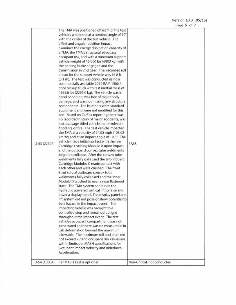
The TMA was positioned offset % of the test
vehicles width and at a nominal angle of 10°
with the center of the test vehicle. The
offset and angular position impact
examines the energy dissipation capacity of
a TMA, the TMA's structural adequacy,
occupant risk, and with a minimum support
vehicle weight of 15,000 lbs (6803 kg) with
the parking brake engaged and the
transmission in 2nd gear. The recorded roll
ahead for the support vehicle was 16.8 ft
(5.1 m). The test was conducted using a
commercially available 2012 RAM 1500 4
door pickup truck with test inertial mass of
4995.6 lbs (2266.0 kg). The vehicle was in
good condition, was free of major body
damage, and was not missing any structural
components. The bumpers were standard
equipment and were not modified for th is
test. Based on CarFax reporting there was
no recorded history of major accidents, was
not a salvage titled vehicle, not involved in
flooding, or fire. The test vehicle impacted
the TMA at a velocity of 64.05 mph (103.08
km/hr) and at an impact angle of 10.3°. The
vehicle made initial contact with the rear 3-53 (2270P) PASS
Cartridge crushing Module A upon impact
and the outboard convex tube weldments
began to collapse. After the convex tube
weldments fully collapsed the two inboard
Cartridge Modules C made contact with
each other and were crushed. The front
Strut sets of outboard convex tube
weldments fully collapsed and the inner
Module D crushed to near a near flattened
state. The TMA system contained the
hydraulic powered vertical lift to raise and
lower a display panel. The display panel and
lift system did not pose or show potential to
be a hazard in the impact event. The
impacting vehicle was brought to a
controlled stop and remained upright
throughout the impact event. The test
vehicles occupant compartment was not
penetrated and there was no measurable in
cab deformation beyond the maximum
allowable. The maximum roll and pitch did
not exceed 75°and occupant risk values are
within limits per MASH specifications for
Occupant Impact Velocity and Ridedown
Acceleration.
3-54 (1500A) Per MASH Test is optional Non-Critical, not conducted
Version 10.0 (05/16)
Page 7 of 7
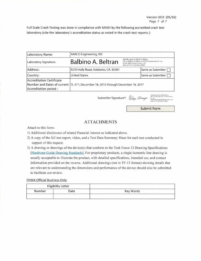
Full Scale Crash Testing was done in compliance with MASH by the following accredited crash test
laboratory (cite the laboratory's accreditation status as noted in the crash test reports .):
Laboratory Name:
Laboratory Signature:
KARCO Engineering, INC
Balbino A. Beltran D191tally si gned by Ba1b1no A. Behran
ON: cn=Balbino A. Beltran, o=KARCO Engineering, LLC ou,
[email protected], c=US
Date: 2017.01.13 16:35:23 -08'00'
Address : 9270 Holly Road, Adelanto, CA. 92301 Same as Submitter 0
Country: United States Same as Submitter 0 Accred itat ion Certificate
Number and Dates of current
Accreditation period :
TL-371 ; December 18, 2015 through December 18, 2017
Submit Form
ATTACHMENTS
Attach to this form:
1) Additional disclosures of related financial interest as indicated above.
2) A copy of the full test report, video, and a Test Data Summary Sheet for each test conducted in
support of this request.
3) A drawing or drawings of the device(s) that conform to the Task Force-13 Drawing Specifications
[Hardware Guide Drawing Standards]. For proprietary products, a single isometric line drawing is
usually acceptable to illustrate the product, with detailed specifications, intended use, and contact
information provided on the reverse. Additional drawings (not in TF-13 format) showing details that
are relevant to understanding the dimensions and performance of the device should also be submitted
to facilitate our review.
FHWA Official Business Only:
Eligibility Letter
Number Date Key Words

Test Article:
Test Program:
SECTION 4
MASH TEST 3-50 SUMMARY
TrafFix Devices Scorpion TL3 TMA
MASH 3-50
Project No.
Test Date:
P361 16-01
06/24/16
SEQUENTIAL PHOTOGRAPHS
0.000 s 0.050 s 0.100s 0.150 s 1.500 s 2.000 s
PLAN VIEW
-60 ft -45 ft -30 ft -15 ft 0 ft 15 ft 30 ft 45 ft
re· est e Miclc e ·veh1c16
,________ 371 ft. -----------<Post-Tost
• Anlcle e ·i1ehicle
• Debris
3.0ft.
10 TR-P36116-01-NC

SECTION 4 ... (CONTINUED)
MASH TEST 3-50 SUMMARY
Test Article: TrafFix Devices Scorpion TL3 TMA Project No. P36116-01
Test Program: MASH 3-50 Test Date: 06/24/1 6
GENERAL INFORMATION EXIT CONDITIONS
TEST AGENCY KARCO Fngineering , 11 C. EXIT VELOCITY
TEST NUMBER P36116-01 EXIT ANGLE
TEST DESIGNATION 3-50 VEHICLE STABILITY Satisfactory
TEST DATE 06/24/16 FINAL VEHICLE POSITION
37.1 ft. (11 .3 m) rearward and 3.0 ft. (0.9 m) left
from its initial point on contact. TEST ARTICLE
NAME/MODEL Scorpion TL3 TMA VEHICLE SNAGGING None
TYPE Truck Mounted Attenuator VEHICLE POCKETING None
KEY ELEMENTS Curved Tubes , Aluminum Honeycomb, Support
Frame, Cartridge Section
MAXIMUM ROLL ANGLE 2.5°
MAXIMUM PITCH ANGLE -5.1'
ARTICLE LENGTH 12.9 ft. (3.9 m) MAXIMUM YAW ANGLE 2.4°
HEIGHT FROM GROUND 11.25 in . (286 mm) KINETIC ENERGY 300.79 kip-ft (407.81 kJ)
MAXIMUM WIDTH 8.0 ft . (2 .4 m) OCCUPANT RISK VALUES
ROAD SURFACE Concrete OCCUPANT IMPACT
VELOCITY
Longitudinal 34.8 tus (10.6 mis)
SUPPORT VEHICLE Lateral 2.6 tus (0 .8 mis)
TOTAL INSTALLATION LENGTH 41.3 ft (12 .6 m) RIDEDOWN
ACCELERATION
Longitudinal -19.2 g
YEAR, MAKE AND MODEL 1991 Ford F700 Lateral -4.8 g
RESTRAINT Blocked Aqainst Roll Ahead THIV 35.1 tus (10.7 mis)
TEST VEHICLE PHO 19.7 g
TYPE I DESIGNATION 1100C ASI 1.37
YEAR, MAKE AND MODEL 2013 Kia Rio TEST ARTICLE DEFLECTIONS
CURB MASS 2,520.9 lbs (1 , 143.5 kg) DYNAMIC DEFLECTION 6.8ft. (2.1 m)
TEST INERTIAL MASS 2,431 .7 lbs (1 , 103.0 kg) STATIC DEFORMATION 5.6 ft . (1.7 m)
GROSS STATIC MASS 2,597.0 lbs (1 , 178.0 kg)
ARTICLE DAMAGE Damage to cartridge, strut and tube sections. IMPACT CONDITIONS
IMPACT VELOCITY 60.83 moh (97 .90 km/h)
IMPACT ANGLE 0.6' VEHICLE DAMAGE
IMPACT LOCATION I ORIENTATION 0.3 in . (8 mm) left of TMA centerline. VEHICLE DAMAGE SCALE 12-FD-3
COLLISION DAMAGE CLASSIFICATION 12FDEW4
11 TR-P36116-01 -NC

Test Article:
Test Program:
SECTION 4
MASH TEST 3-51 SUMMARY
TrafFix Devices Scorpion TL3 TMA
MASH 3-51
Project No.
Test Date:
P35200-01
10/22/15
SEQUENTIAL PHOTOGRAPHS
0.000 s 0.050 s 0.150 s 0.250 s 0.750 s 1.800 s
PLAN VIEW
-60 ft -45 ft -30 ft -15 ft 0 ft 15 ft 30 ft 45 ft
p イセ t q g エ@
e A.nkle vセ@ lidH
Poot·Teot e 1\r11c1o
• Ve1ilcie • f")i..-h1is
f-------- 111 n -------1 •
i on
9 TR-P35200-01 -A

SECTION 4 .. . (CONTINUED)
MASH TEST 3-51 SUMMARY
Test Article: TrafFix Devices Scorpion TL3 TMA Project No. P35200-01
Test Program: MASH 3-51 Test Date: 10/22/1 5
GENERAL INFORMATION EXIT CONDITIONS
TEST AGENCY KARCO Engineering , LLC . EXIT VELOCITY
TEST NUMBER P35200-01 EXIT ANGLE
TEST DESIGNATION 3-51 VEHICLE STABILITY Satisfactory
TEST DATE 10/22/15 37.1 ft. (11 .3 m) rearward and 1.0 ft. (0.3 m) right FINAL VEHICLE POSITION
TEST ARTICLE from its initial point on contact.
NAME / MODEL Scorpion TL3 TMA VEH ICLE SNAGGING None
TYPE Truck Mounted Attenuator VEH ICLE POCKETING None
Cuived Tubes , Aluminum Honeycomb, Support MAXIMUM ROLL ANGLE -1 .8' KEY ELEMENTS
Frame, Cartridge Sections MAXIMUM PITCH ANGLE -5.9'
ARTICLE LENGTH 12.9 ft . (3 .9 m) MAXIMUM YAW ANGLE -2.3'
HEIGHT FROM GROUND 11 .75 in . (298 mm) KINETIC ENERGY 656 .6 kip-ft (889.8 kJ)
MAXIMUM WIDTH 8.0 ft. (2.4 m) OCCUPANT RISK VALUES
ROAD SURFACE Concrete OCCUPANT IMPACT Longitudinal 38 .7 fUs (11 .8 mis)
SUPPORT VEHICLE VELOCITY Lateral 1.0 fUs (0 .3 mis)
TOTAL INSTALLATION LENGTH 41 .3 ft (12 .6 m) RIDEDOWN Longitudinal -20.0g
YEAR , MAKE AND MODEL 1991 Ford F700 ACCELERATION Lateral -3.7 g
RESTRAINT Blocked Aoainst Roll Ahead THIV 38.4 fUs (11 .7 mis)
TEST VEHICLE PHO 20.1 g
TYPE I DESIGNATION 2270P ASI 1.46
YEAR , MAKE AND MODEL 2012 RAM 1500 TEST ARTICLE DEFLECTIONS
CURB MASS 4,901 .9 lbs (2,223.5.0 kg) DYNAMIC DEFLECTION 7.9 ft. (2.4 m)
TEST INERTIAL MASS 4,920.6 lbs (2 ,232 .0 kg) STATIC DEFORMATION 7.2 ft. (2 .2 m)
GROSS STATIC MASS 4,920.6 lbs (2,232 .0 kg) Damage to backup structure, strut section ,
IMPACT CONDITIONS ARTICLE DAMAGE cartridge section , and tubes. Module C detached.
IMPACT VELOCITY 63.16 mph (101.65 km/h)
IMPACT ANGLE 0.9' VEHICLE DAMAGE
VEHICLE DAMAGE SCALE 12-FD-5 IMPACT LOCATION I ORIENTATION 0.7 in . (18 mm) right of TMA center1ine.
COLLISION DAMAGE CLASSIFICATION 12FDEW2
10 TR-P35200-01-A

Test Article:
Test Program :
SECTION 4
MASH TEST 3-52 SUMMARY
TrafFix Devices Scorpion TL3 TMA
MASH 3-52
Project No.
Test Date:
P36206-01
08/22/16
SEQUENTIAL PHOTOGRAPHS
0.000 s 0.050 s 0.150 s 0.250 s 0.500 s 2.000 s
PLAN VIEW
-30 ft -15 ft 0 ft 15 ft 30 ft 45 ft
Prll·Test e Article
・ v ・ ィ ゥ」ャ セ@
Post-Test
aイエゥ ・ セ@
e VehirJ"l
9 TR-P36206-01 -NC
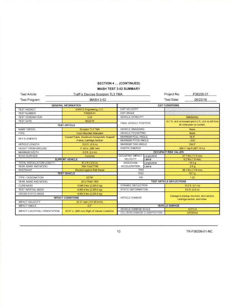
SECTION 4 ... (CONTINUED)
MASH TEST 3-52 SUMMARY
Test Article : TrafFix Devices Scorpion TL3 TMA Project No. P36206-01
Test Program: MASH 3-52 Test Date: 08/22/16
GENERAL INFORMATION EXIT CONDITIONS
TEST AGENCY KARCO Fnginooring , 11 C. EXIT VELOCITY
TEST NUMBER P36206-01 EXIT ANGLE
TEST DESIGNATION 3-52 VEHICLE STABILITY Satisfactory
TEST DATE 08/22/16 FINAL VEHICLE POSITION
15. 7 ft. (4.8 m) forward and 9.2 ft . (2.8 m) left from
its initial point on contact. TEST ARTICLE
NAME /MODEL Scorpion TL3 TMA VEHICLE SNAGGING None
TYPE Truck Mounted Attenuator VEHICLE POCKETING None
KEY ELEMENTS Curved Tubes , Aluminum Honeycomb, Support
Frame, Cartridge Section
MAXIMUM ROLL ANGLE 18.9°
MAXIMUM PITCH ANGLE -14.8°
ARTICLE LENGTH 12.9 ft . (3 .9 m) MAXIMUM YAW ANGLE 1045°
HEIGHT FROM GROUND 11 .42 in . (290 mm) KINETIC ENERGY 669.11 kip-ft (907.19 kJ)
MAXIMUM WIDTH 8.0 ft . (2.4 m) OCCUPANT RISK VALUES
ROAD SURFACE Concrete OCCUPANT IMPACT
VELOCITY
Longitudinal 37.7 IVs (11 .5 mis)
SUPPORT VEHICLE Lateral 6.2 IVs (1 .9 mis)
TOTAL INSTALLATION LENGTH 41.3 ft (12 .6 m) RIDEDOWN
ACCELERATION
Longitudinal -186 g
YEAR, MAKE AND MODEL 1991 Ford F700 Lateral -2 .6 g
RESTRAINT Blocked Against Roll Ahead THIV 38.11Vs(11 .6mls)
TEST VEHICLE PHD 18.7 g
TYPE I DESIGNATION 2270P ASI 1.22
YEAR, MAKE AND MODEL 2012 RAM 1500 TEST ARTICLE DEFLECTIONS
CURB MASS 5,046.3 lbs (2,289.0 kg) DYNAMIC DEFLECTION 10.2 ft . (3.1 m)
TEST INERTIAL MASS 4,993.4 lbs (2 ,265.0 kg) STATIC DEFORMATION 9.2 ft . (2.8 m)
GROSS STATIC MASS 4,993.4 lbs (2 ,265.0 kg)
ARTICLE DAMAGE Damage to backup structure, strut section,
ca1ridge section , and tubes. IMPACT CONDITIONS
IMPACT VELOCITY 63.31 mph (101 .89 km/h)
IMPACT ANGLE 0.2· VEHICLE DAMAGE
VEHICLE DAMAGE SCALE 12-FD-4 IMPACT LOCATION I ORIENTATION 26.97 in. (685 mm) Right of Vehicle Centerline.
COLLISION DAMAGE CLASSIFICATION 12FDEW2
10 TR-P36206-01-NC

SECTION 4
MASH TEST 3-53 SUMMARY
Test Article : TrafFix Devices Scorpion TL3 TMA Project No. P36129-01
Test Program: MASH 3-53 Test Date: 09/07/16
SEQUENTIAL PHOTOGRAPHS
0.000 s 0.050 s 0.150 s 0.300 s 0.500 s
PLAN VIEW
-30 ft -15ft Oft 15 ft 30ft 45ft 60 ft 75 ft
1.200 s
Pre·THI
e.l\rtJcle • Venicle
P0&t-Test
e Arh1:k1
e VePliele
10 TR-P36129-01 -NC

SECTION 4 ... (CONTINUED)
MASH TEST 3-53 SUMMARY
Test Article: TrafFix Devices Scorpion TL3 TMA Project No. P36129-01
Test Program: MASH 3-53 Test Date: 09/07/16
GENERAL INFORMATION EXIT CONDITIONS
TEST AGENCY KARC0 Fnginooring , l l C. EXIT VELOCITY
TEST NUMBER P3612S-01 EXIT ANGLE
TEST DESIGNATION 3-53 VEHICLE STABILITY Satisfactory
TEST DATE 09/07/16 48.2 ft. (14 .7 m) forward and 24.3 ft . (7.4 m) left FINAL VEHICLE POSITION
TEST ARTICLE from its initial point on contact.
NAME / MODEL Scorpion TL3 TMA VEHICLE SNAGGING None
TYPE Truck Mounted Attenuator VEHICLE POCKETING None
Curved Tubes , Aluminum Honeycomb, Support MAXIMUM ROLL ANGLE 37.2' KEY ELEMENTS
Frame, Cartridge Section MAXIMUM PITCH ANGLE 20.9'
ARTICLE LENGTH 12.9 ft. (3 .9 m) MAXIMUM YAW ANGLE 164.6'
HEIGHT FROM GROUND 11 .02 in . (280 mm) KINETIC ENERGY 685.12 kip-ft (928 .10 kJ)
MAXIMUM WIDTH 8 .0 ft. (2.4 m) OCCUPANT RISK VALUES
ROAD SURFACE Concrete OCCUPANT IMPACT Longitudinal 35.8 IVs (10.9 mis)
SUPPORT VEHICLE VELOCITY Lateral 3.9 IVs (1 .2 mis)
TOTAL INSTALLATION LENGTH 41 .3 ft (12 .6 m) RIDEDOWN Lonaitudinal -12.5 g
YEAR, MAKE AND MODEL 1991 Ford F700 ACCELERATION Lateral -4.9 g
RESTRAINT 2nd aear and oarkina brake enn""ed THIV 36.1 IVs (11 .0 mis)
TEST VEHICLE PHO 12.8 g
TYPE I DESIGNATION 2270P ASI 1.10
YEAR, MAKE AND MODEL 2012 RAM 1500 TEST ARTICLE DEFLECTIONS
CURB MASS 4,964.7 lbs (2,252.0 kg) DYNAMIC DEFLECTION 11 .2 ft. (3.4 m)
TEST INERTIAL MASS 4,995.6 lbs (2,266.0 kg) STATIC DEFORMATION 10.8 ft. (3 .3 m)
GROSS STATIC MASS 4,996.6 lbs (2,266.5 kg) Damage to backup structure, strut section,
IMPACT CONDITIONS ARTICLE DAMAGE catridge section, and tubes.
IMPACT VELOCITY 64.05 mph (103.08 km/h)
IMPACT ANGLE 10.3' VEHICLE DAMAGE
VEHICLE DAMAGE SCALE 12-FD-4 IMPACT LOCATION I ORIENTATION 10' and 20.6 in . (523 mm) from vehicle centeriine
COLLISION DAMAGE CLASS IFICATION 12FDEW2
11 TR-P36129-01 -NC

UMRセ@ 7.7" .._____ [ ! N@ QMMMM NNjセMMMMMMQ R N@ S }@ _________
ゥMMMM MMMMMMMMM Q@ R N Y MMMMMMMMMMMMセ@[J.1 ]
...
l 3 s」ッ イ ッ ゥ@ ZZ^セ@ TM A
GllOUND :J¥tC NO. REVi セ@l'"11'... 1000-162 A
YiEE1 1 0 : 2
Figure 1:TL3 Scorpion TMA Sheet 1 of 2
D-1 TR-P36129-01-NC

ITll£
L3 Scoro or T.\i'A
:tNG t.O.
ゥ PPセ Q@ VR@NOTE5. UN E5S orHaW/5E sncmn> EET 20f :t
Figure 2:TL3 Scorpion TMA Sheet 2 of 2
D-2 TR-P36129-01-NC