evaluation highway runoff pollution control...
TRANSCRIPT

Evaluation of Highway Runoff Pollution Control Devices
Final Report Task Order #43 Project 7620
New Jersey Department of Transportation December 23, 1996
submitted by
Dr. B.D. Hayes, Rutgers University Dr. T.F. Marhaba, New Jersey Institute of Technology N. W. Agnoli, Rutgers University D.M. Lackey, New Jersey Institute of Technology

Technkol Report Doeurnentotion Pogo
Hayes, B.D., T.F. Marhaba, N.W. Agnoli, D.M. Lackey . . ..
9. P e r f o m l q Orgonlwlon None oad Addrear 10. UhII NO. (TRAIS) Rutgers University
P.O.B. 909 Piscataway, NJ 08855-0909
New Jersey Department of Transportation Bureau of Research
Trenton NJ 08625-0600
Department of Civil and Environmental Engineering
. - . . . , .. , , .. I -.. 12. bonrmrlng Afency Name UI A d h e .
CN 600 . . , . . .-
I
11. Conwoec si &on* He. Research Study 7620
Final Report April 1 1996 to December 31, 1996
??* . 'Y ..! R?P?!!. 9!$,P.!L.?,Gr.!d. -., , ,
14- hsaemdne Aemncy Code
. . . .. . .
Information on existing and innovative pollution control technologies for highway runoff has been used to evaluate the potential of each tecbnology in the four physiographic regions characterizing New Jersey. Technologies were evaluated for applicability under the following criteria: performance, cost, maintenance, failure rates, site requirements, contributing watershed drainage area, and regional space availability. In the Coastal Plain, wetlands, dry detention basins, wet detention ponds, grass swales, and g&s filter strips have demonstrated the potential to act as effective water quality control devices. Research is necessary on sediment r6moval by forebays in systems that detain water for treatment. Sediment removal greatly reduces costly maintenance. In the Piedmont region, wetlands, dry detention basins, wet detention ponds, grass swales, and grass filter strips are well suited to treat highway runoff. Compost Stormwater FiltersTM and sand filters may also be suitable in this region. Efficiency, cost, maintenance, and long term effectiveness in regions that experience changing seasons require study before the implementation of the sand and compost-media filters. In the Highlqds region, Compost Stormwater FiltersTM and sand filters may be applicable. Grass swales and wetlands may also accomplish water quality goals. Research is again necessary on wetland forebays and both filter systems. In the Valley and Ridge Region, Compost Stormwater Filtersm and sand filters meet the necessary requirements for success. Wetlands, grass swales, and grass filter strips may also be utilized in the Valley and Ridge region. Porous pavement, oil grit separators, and infiltration systems have low potential for use in any of the four physiographic regions due to difficulties associated with performance, maintenance, and cost. Not all the information acquired from available literature is directly applicable to this study. Many studies were performed in regions with significantly different soil characteristics and field conditions which suggests the importance of local demonstration projects.
Research requirements in this region are similar to that necessary in the Highlands.
13. Key Werdi I
stormwater, pollution, non-point source, highway, wetlands, filters, detention basins
11. Dholkt lsn b8miwrnc
No Restfictions
...

ACKNOWLEDGEMENT
Support for this study was provided by the New Jersey Department of Transporation in cooperation with the USDOT Federal Highway Administration. Mr. Szalaj and Mr. Kaminsky of NJDOT's Bureau of Environmental Analysis and Mr. Marsella, the NJDOT project manager, are gratehlly acknowledged for making their expertise available through frequent meetings. Students at both Rutgers and NJIT are additionally acknowledged for their contribution to this study.
NOTICE
The United States government does not endorse products or manufacturers. Trade or manufacturers' names appear herein solely because they are considered esssential to the object of this report.
DISCLAIMER STATEMENT

ABSTRACT Information on existing and innovative pollution control technologies for highway runoff has been used to evaluate the potential of each technology in the four physiographic regions characterizing New Jersey. Technologies were evaluated for applicability under the following criteria: performance, cost, maintenance, failure rates, site requirements, contributing watershed drainage area, and regional space availability. In the Coastal Plain, wetlands, dry detention basins, wet detention ponds, grass swales, and grass filter strips have demonstrated the potential to act as effective water quality control devices. Research is necessary on sediment removal by forebays in systems that detain water for treatment. Sediment removal greatly reduces costly maintenance. In the Piedmont region, wetlands, dry detention basins, wet detention ponds, grass swales, and grass filter strips are well suited to treat highway runoff. Compost Stormwater FiltersTM and sand filters may also be suitable in this region. Efficiency, cost, maintenance, and long term effectiveness in regions that experience changing seasons require study before the implementation of the sand and compost- media filters. In the Highlands region, Compost Stormwater FiltersTM and sand filters may be applicable. Grass swales and wetlands may also accomplish water quality goals. Research is again necessary on wetland forebays and both filter systems. In the Valley and Ridge Region, Compost Stormwater FiltersTM and sand filters meet the necessary requirements for success. Wetlands, grass swales, and grass filter strips may also be utilized in the Valley and Ridge region. Research requirements in this region are similar to that necessary in the Highlands. Porous pavement, oil grit separators, and infiltration systems have low potential for use in any of the four physiographic regions due to difficulties associated with performance, maintenance, and cost. Not all the information acquired from available literature is directly applicable to this study. Many studies were performed in regions with significantly different soil characteristics and field conditions which suggests the importance of local demonstration projects.

i
TABLE OF CONTENTS
List of Figures
List of Tables and Maps
1 .O Introduction
2.0 Stormwater Management Practices
2.1 Oil Grit Separators
2.2 Compost Stormwater FiltersTM
2.3 Constructed Wetlands
2.4 Dry Detention Ponds
2.5 Wet Detention Ponds
2.6 Multiple Pond System
2.7 Sand Filters
2.8 Infiltration Trenches
2.9 Infiltration Basins
2.10 Grass Swales
2.11 Grass Filter Strips
2.12 Porous Pavement
3.0 New Jersey's Physiographic Regions
3.1 Outerhner Coastal Plain
3.2 Piedmont
3.3 Highlands
3.4 Valley and Ridge
4.1 Recommended SMPs for New Jersey's Physiographic Regions
4.2 Alternative Methods Requiring Research
4.3 Reduction of Salt Runoff in All Physiographic Regions
4.4 Rejected Methods
4.0 Recommendations
5.0 References
Appendix A: Acronyms and Glossary
Appendix B: Characteristics of Highway Runoff
Appendix C: Deicing Alternatives and Spreading Efficiency Improvements
Appendix D: Processes in the Environment
Appendix E: Discussion of Devices
Appendix F: Legislation
Appendix G: Physiographic Regions of the United States
f3B ii
iii
i
3
3
3
4
4
5
5
6
6
7
7
8
8
14
15
15
16
16
20
20
24
28
30
37
A- 1
B-1
c-I D-I
E-I
F-I
G-I

Flaure c. 1
E. 1
E.2 E.3
E.4
E.5
E.6
E.7
E.8
E.9
E.10
E . l l
E.12
E.13
E.14
E.15
F.l
G. 1
LIST OF FIGURES
Spinner Spreader Accuracy vs. Zero Velocity Spreader Accuracy
Oil Grit Separator
Compost Stormwater Filter Units: “Drop-In”, Surface and Subsurface
Sustainable Maintenance Cycle
Constructed Wetland
Extended Detention Pond
Wet Detention Pond
Multiple Pond System Design
Enhanced Wet Extended Detention Pond
Sand Filter Design
Infiltration Trench Design
Infiltration Basin
Grass Swale
Check Dam
Grass Filter Strip
Side-View of Porous Pavement
Map of New Jersey’s Coastal Wetlands and Pinelands
Map of the 28 Physiographic Regions of the United States
J3w c-5
E-3
E-7
E-9
E-I 5
E-20
E-24
E-28
E-28
E-32
E-35
E-38
E-42
E43
€ 4 6
E-50 F 4
G-2

Tables 2.1
2.2
2.3
4.1
4.2a
4.2b
4.3
4.4
... 111
LIST OF TABLES AND MAPS
Removal Efficiencies of Stormwater Management Practices
SMP Cost Comparison Table
SMP Contributing Watershed Drainage Area
Physiographic Considerations for Structural Practices to Control the Quality
of Stormwater Runoff
Evaluation of Facility Maintenance Requirements for Four Maryland Counties
Criteria Used in Performance Evaluations of Facility Maintenance
Requirements for Four Maryland Counties
Criteria Used in Evaluating Performance in 1986 and 1990
Rejected Methods
M a s 3.1 New Jersey’s Highways in the Four Physiographic Regions
3.2 New Jersey’s Counties in the Four Physiographic Regions
3.3 New Jersey’s Topography in the Four Physiographic Regions
4.1 Recommended SMPs for Each Physiographic Region
mJe 10-1 1
12
13
25-26
34
34
35
36
17
18
19
27

1 .O INTRODUCTION This study was performed to accomplish three objectives. The first objective was to research established and innovative mitigation technologies or Stormwater Management Practices (SMPs) applicable to highway runoff in New Jersey. The second objective was to recommend technologies best suited for each of the four physiographic region in this state. The final objective was to identify the technologies that require additional research. SMP methodologies were evaluated based on the criteria of performance, failure rates, maintenance requirements, and cost.
Highway runoff can be a non-point source (NPS) pollutant. It can originate from rainfall or snowmelt moving over and through ground surfaces containing pollutants. The stormwater collects these pollutants and then transports them to lakes, rivers, wetlands, coastal waters, and underground sources of drinking water. Examples of highway runoff pollutants include oil, grease, and salt from deicing materials. Before a SMP can be efficiently employed, the physical, chemical, and biological components of the runoff must be identified and quantified [see Appendix 6). Each stormwater runoff facility has the potential to remove a specified range of pollutants; therefore, potentially appropriate SMP technologies can be identified by the contaminants present in the runoff as well as cost, maintenance requirements, and site specific characteristics such as drainage area and land available.
New Jersey has four distinct physiographic regions: Outerllnner Coastal Plain, Piedmont, Highlands, and Valley and Ridge. Each region possesses unique features such as soil type, elevation, and slopes that affect the recommendation of appropriate SMPs. Studies from local states characterized with similar regions are used to substantiate the conclusions made in this document.
The most efficient pollution control strategy is prevention. Highways and other surfaces used by vehicles can contribute a wide range of pollutants to stormwater. Many of these pollutants are directly proportional to traffic volume. A greater concentration of pollutants will be observed in areas with greater traffic volume when compared to similar locations with lighter traffic. Reduction of trafic loads is not always an implementable option particularly in the State of New Jersey due to its many urban areas and high population density. Consequently, the following SMP technologies may be utilized to control runoff pollutants: deicing alternatives and spreading efficiency improvements, oil grit separators, Compost Stormwater FiltersTM, wetlands, dry detention basins, wet detention ponds, multiple pond systems, sand filters, infiltration trenches, infiltration basins, grass swales, grass filter strips, and porous pavement. A brief discussion of each technology’s characteristics and criteria are presented below. Information has also been tabulated at the end of this section. Table 2.1 on

2
pages I 0 and 11 summarizes the removal efficiencies of each SMP. Table 2.2 on page 12 presents a cost comparison of each technology. A description of this table follows below. Finally, Table 2.3 on page 13 details the contributing watershed drainage capacity of each technology. A thorough description of each technology can be found in Appendix E and deicing alternatives and spreading efficiency improvements can be found in Appendix C.
Initial cost represents all costs associated with site preparation, equipment, construction and start up. All technologies have associated maintenance costs for activities which could range from a minimal periodic inspection to frequent cost-intensive procedures. In order to compare the relative cost of technologies, initial costs and maintenance costs must be considered. Lifetime costs represent the initial cost and the present value of annual maintenance costs assuming a performance period of 50 years with an interest rate of 7 percent. This performance period reflects the maximum useful lifespan desired and is limited by the lifespan of other essential elements of the associated roads and highways. The interest rate of 7 percent is consistent with the value currently recommended by the USEPA for use on feasibility studies. All technologies have an expected lifespan of at least 50 years assuming proper maintenance.
Certain technologies, most notably oil grit separators, are likely to fail if not properly maintained. If these are to be implemented, adequate funds should be escrowed to cover maintenance over the entire desired performance period. The likelihood of failure of most technologies due to inadequate performance can not accurately be forecasted due to a lack of long term field performance data. The lifetime costs listed in Table 2.2 reflect the initial cost plus the amount of money to be escrowed for maintenance. For lifespans less than 50 years, less money would need to be escrowed; however, this amount is relatively insensitive for lifespans greater than 20 years. Lifetime costs for all technologies in Table 2.2 decrease approximately 10% when the lifespan is decreased from 50 to 20 years.
Source reduction opportunities are related to recent developments in road deicing practices. Alternatives to conventional salt and improvements in salt application can be employed to combat the adverse effects that road salt has on the environment.

2.0 STORMWATER MANAGEMENT PRACTICES 2.1 Oil Grit Separators
Oil grit separators can be used to remove hydrocarbons, rubbish, and sediment from runoff [see Table 2.1, pp. 10-111. The system does not present any aesthetic concerns because it is completely underground. Oil grit separators are easy to construct, save space, and, when used with other systems, could effectively reduce the maintenance requirements of other SMPs. The maximum drainage area of these systems is two acres [see Table 2.3, p. 131. Maintenance is the key to this system’s effectiveness and is costly. Oil grit separators require regular inspections and cleaning twice a year. Large storms can flush through the system, resuspend settled contaminants, and reintroduce them into the environment. Hydrocarbon removal in urban areas have been reported to be 83.7 percent; however, some studies indicate no removal of hydrocarbons (83). Without continuous maintenance and inspections, the systems will fail (35). Confined space entry will be required for these maintenance activities. If the system fails, it can be retrofitted into a sand filter, compost filter, or an infiltration trench.
2.2 Compost Stormwater FiltersTM
The Compost Stormwater Filter (CSFTM) represents an innovative technology for runoff pollution control. This system has shown promising removal efficiencies for sediment, metals, and organics [see Table 2.1, pp. 10-1 11. One ideal feature of the CSFTM is the space-saving design. Also, CSFTM has designed a new system with removable, rechargeable cartridges that increase the ease of maintenance of the current system. The compost produced is odorless, and the retired media can be used for landscaping, erosion control, or as daily cover on landfills as per EPA 503 regulations [see Appendix F]. Potential negative factors inherent to the system include low maximum water volumes and the limited volume of data available on the long- and short-term operation, maintenance, and cost of a CSFTM system. If the flow into the system exceeds the maximum, water can pond over the compost, bypass processing, and discharge untreated. The scum baffles will still remove floatables, solids, and surface films. The cost of this system is high in comparison to other SMPs [see Table 2.2, p.121. Maintenance requirements include removing compost and sediments annually. The CSFTM manual suggests four inspections per year which involve debris removal and determining the need for major maintenance. Safety may be an issue if an open system is installed. Research into the long-term operation, the effect of four seasons on the system, and the actual maintenance requirements of a CSFTM system is necessary. If the CSFTM system fails, it cannot be retrofitted.

4
2.3 Constructed Wetlands
Constructed wetlands can also be used as an effective SMP. The ability of natural and constructed wetlands to purify water is well documented [see Table 2.1, pp. 10-1 11. The Florida Department of Environmental Regulation (FDER) allows regular permitting of stormwater and wastewater discharges into certain natural wetlands provided that pretreatment of stormwater and criteria for design and performance of output facilities are met (130). The effective treatment area of a wetland system is 5 to 99 acres (28) [see Table 2.3, p. 131. Wetlands’ self- reliance is a major economic incentive for their use [see Table 2.2, p. 121. The system can be adapted or modified to work effectively in most regions of the country. The addition of a forebay or large detention pond efficiently removes pollutants, sediments, and pollutants adsorbed onto sediments before they enter the wetland system (12). It is beneficial to the system if 85 percent of the sediments can be removed before the runoff enters the wetlands (13). With a forebay or detention pond added to the system, the low maintenance requirements already present in the system are further reduced. The maintenance performed with a forebay or pond attachment is less disruptive because it mainly occurs in these attachments. Compartmentalization of the wetland system allows maintenance to be performed in sections. In the wetland, sediment removal should occur approximately every 20 years. The life expectancy of an artificial wetland system is approximately 75 years (35). Potential problems involved with the wetland system include downstream warming before the canopy cover is established (in forested wetlands), increased mosquito population, low pollutant removal in winter months, and regulatory problems which may be caused by the addition of pollutants into a mitigation system (28). Roughly 15 years are required for planted vegetation to become established and effective in a forested wetland (44). The United States Army Corp of Engineers Section 404 permit requires an 80 percent success rate for constructed wetland vegetation (72). This system cannot be employed in areas where space available for SMP operations is limited. Safety factors must be considered when implementing this system. If a wetland system fails because it becomes dry or the planted vegetation dies, it can be retrofitted into a detention system.
2.4 Dry Detention Basins
Dry detention basins are a SMP option in areas with a water table that rests several feet below the bottom of the basin. The basins provide moderate but variable removal of particulate pollutants and a limited removal of soluble pollutants [see Table 2.1, pp. 10-1 I] . Studies have shown than rain events with unusual intensity reduce the detention time in the basin; therefore, the removal of pollutants is limited (39). Soil types effect the performance of this system. If the soil is permeable, the possibility of groundwater contamination exists, and if the soil is impermeable, standing water will be present. The maintenance of dry
5
detention basins is both essential and costly. This SMP has the highest routine maintenance burden of the available technologies due to mowing and clogging problems. Control measures such as regrading, revegetation, and riprap protection may be necessary to prevent erosion of the basin’s structures (48). Poorly maintained dry detention basins are usually unpopular with nearby residents because of mosquitoes and unsightly weed growth. If improperly sited, dry detention ponds can cause damage to water quality, existing forests, wetland destruction, or downstream warming. If failure occurs, dry detention basins can be retrofitted into a wetland system. This SMP requires a large quantity of land to implement.
2.5 Wet Detention Ponds
Sediment within the wet detention pond acts as a pollutant trap (117). Trapping allows a significant fraction of the pollutant loading to be permanently retained or degraded [see Table 2.1, pp. 10-111. Wet ponds are considered the most effective pollutant removing detention facilities. Wet ponds are most effective in areas with a shallow groundwater table which allows water to pond in the system. A forebay or a wetland along the fringe or within the wet pond can be added to the design of the facility to achieve higher pollutant removal (127). Maintenance requirements for this facility are low; however, maintenance is essential for effective operation. Sediment should be removed every 10 to 25 years (103). Weed removal, grass mowing, erosion control, and debris removal from the inlet and outlet structures should be performed. Along with dry detention basins, wet detention ponds can cause damage to water quality, existing forests, wetland destruction, or downstream warming if improperly sited. Also, wet ponds cost 10 to 20 percent more than conventional detention basins (35) [see Table 2.2, p. 121. Recent field assessments have shown most wet ponds functioning as designed and had few reported failures (35). Failures can result from pond construction in areas where the water table cannot support the pond especially in dry periods. Safety issues must be evaluated when employing this technology. Wet ponds cannot be used in areas with space constraints.
2.6 Multiple Pond Systems
The multiple pond system technology has emerged over the last five years. The use of multiple pond systems increases the removal of pollutants [see Table 2.1, pp. 10-1 11 while decreasing the pollutant load by spreading the load over several units and lowering maintenance requirements (35). These systems are extremely flexible in their design and a treatment train can be assembled to specifically treat the pollutants present. The life expectancy of this system will be comparable to the technologies used in the train or higher due to the decreased loading on each unit (1 10). If failure occurs, the system can be retrofitted into a wetland, dry detention basin, or wet detention pond. Safety will be a factor if wet detention ponds are part of the system. This system will require a larger amount

6
of land because of the combination of technologies. As a promising innovative technology, a need for research in the areas of removal efficiencies, maintenance, and cost exists.
2.7 Sand Filters
Sand filters are another SMP that can be considered an innovative technology. Sand filters remove particulate such as sediment and trace metals efficiently. Low to moderate removal of soluble pollutants have been observed [see Table 2.1, pp. 10-111. Sand filters in Austin, Texas have displayed removal rates of 85% for sediment, 35% for nitrogen, 40% for fecal coliform, and 50% to 70% for trace metals (35). Sand filters are adaptable to various conditions. They can be designed to filter runoff from a maximum watershed areas of up to 50 acres (1 02). The design of the system prevents sediment resuspension which reduces clogging. An experimental version of the sand filter, the peat sand filter, displays the same removal as the sand filter and provides soluble nutrient removal as well (35). Sand filters require simple and inexpensive maintenance. The facility should be inspected once or twice a year and sediment laden sand should be removed and replaced when necessary. The cost of building this system is estimated at 3 to 4 times the amount necessary to build an infiltration trench [see Table 2.2, p. 121 and increases significantly if the filter is subjected to vehicle loading. Sand filters are especially useful in areas where limited space is available for stormwater runoff quality control (102). They have been recommended over oil grit separators because of their high removal rates and pollutant retention history (42). Sand filters have only been used extensively in Austin, Texas. One thousand filters have been installed in Austin and few have failed. The oldest system has been in operation for 10 years (35). Further information on peat sand filters, failure rates, the effect of four seasons on the system, maintenance requirements, and the disposal of spent sand is needed.
2.8 Infiltration Trenches
Infiltration trenches are a SMP option that provides reduced surface runoff volume, groundwater recharge, reduced thermal impacts on fisheries. Infiltration trenches can be operated in areas were limited space is available. When operating as designed, this system provides a high particulate pollutant removal rate and a moderate soluble pollutant removal rate [see Table 2.1, pp. 10-111. Infiltration trenches provide a cost-effective option for smaller sites that cannot support the larger SMPs [see Table 2.2, p. 121. Application of this system is limited by the depth to groundwater and soil type. The maximum drainage area this system can handle is 5 acres. Infiltration trenches may not be appropriate in areas that experience long, cold winters because the freezing of the soil would prevent contaminant removal. A risk of groundwater contamination is associated with infiltration trenches. In Maryland, groundwater samples taken downgradient from these facilities exceeded drinking water maximum contaminant levels for

7
aluminum, cadmium, chloride, chromium, and lead (59). Also, deep trenches may require an Underground Injection Control (UIC) permit [see Appendix F]. Regular maintenance is required to avoid clogging of the lower layers and the filter fabric which would lead to the excavation and total replacement of the system. Inlet structures should also be inspected for clogging. This system can be retrofitted into a sand filter, compost filter, or a dry detention basin.
2.9 Infiltration Basins
Infiltration basins are a treatment option similar to infiltration trenches. Basins provide groundwater recharge, reduce surface runoff volume, augment low-flow stream conditions, and reduce thermal impacts on fisheries. Application of this system is limited by soil type and depth to groundwater. Similar to infiltration trenches, basins should not be used in regions that experience long, cold winters and may fall under UIC regulations [see Appendix F]. Infiltration basins provide high particulate removal and moderate soluble pollutant removal [see Table 2.1, pp. 10-1 I]. Forebays can be installed to reduce the prevalence of clogging in the system and increase pollutant removal. A risk of groundwater contamination is also associated with infiltration basins. In addition to the contaminant levels cited in the groundwater downgradient from trenches, concentrations of barium, copper, nickel, and zinc were detected in the groundwater downgradient of the trenches (59). This system is maintenance intensive and the primary cause of failure is clogging. None of the 12 basins installed in Maryland would treat runoff after 5 years (92). Basins are not an option if available space is limited. If failure occurs, basins can be retrofitted into wet ponds, dry detention basins, or wetland systems.
2.10 Grass Swales
Historically, grass swales have been utilized in highway medians. Detention time in the grass swale will influence pollutant removal. If outfitted with check dams, this system displays high particulate pollutant removal and moderate soluble pollutant removal [see Table 2.1, pp. 10-111. Without the check dams, low to moderate removal of particulate and soluble pollutants was observed (1 10). Swales are also effective in trace metal removal (98) [see Table 2.1, pp. 10-111. Regions containing sandy soils should not be considered for this technology unless soil modification occurs because the slopes are difficult to maintain due to erosion. Grass swales are economical [see Table 2.2, p.121 and easy to construct. They require minimal maintenance consisting of securing a dense grass cover, periodic sediment removal, check dam inspection, weed control, occasional grass mowing, and spot vegetation repair. Grass swales will last indefinitely provided that this maintenance is performed. If failure does occur, the system can be retrofitted into a grass filter strip.

8
2.1 1 Grass Filter Strips
Filter strips are vegetated sections of land, adjacent to highways, that treat low velocity sheet flow. These systems are not natural buffers, rather they are partially or entirely engineered systems designed for runoff quality and provide minimal quantity control. These systems differ from grass swales in that swale systems are channelized systems while vegetative filter strips are level systems with thick vegetation that is not designed to be submerged (35) and, when large enough can provide a wildlife habitat. Grass filter strip systems have been found to be more effective than forested filter strip systems and will be discussed exclusively (1 20). These systems utilize erosion-resistant grasses on relatively flat slopes for pollutant removal (76). Removal efficiency is affected by the type of flow entering the system, width of the system, depth of flow, thickness of vegetative cover, depth to groundwater, and presence of weeds. Filter strips are effective in removing sediment, organics, and trace metals, but soluble pollutant removal is dependent on site-specific conditions [see Table 2.1, p. 10-111. The incoming runoff must be low velocity sheet flow (107). Areas prone to channel flow can install a level spreader to establish sheet flow. A study in Virginia indicated that 60 percent of the filter strips have failed because of short-circuiting due to a lack of sheet flow (120). The maximum contributing drainage area of this system should be around 5 acres to avoid channelized flow [see Table 2.3, p. 131, and the cost of grass filter strips is low compared to other SMPs [see Table 2.2, p. 121. Filter strips fail easily if they are not properly maintained (13). Frequent maintenance activities such as weeding, reseeding, and replanting will decrease after the first 2 years when dense vegetation is established. Sediment removal and regrading may be performed when necessary. If failure does occur, filter strips can be retrofitted into a grass swale, detention system, or wetland. Research on this system has mainly involved agricultural use, and research into its application to highway runoff must be conducted.
2.12 Porous Pavement
Porous pavement, an infiltration technology, is also a SMP option. Porous pavement recharges groundwater and can decrease the possibility of streambank flooding and thermal shock to aquatic species. The permeability of the soil present at the intended site will govern the applicability of porous pavement. Flooding will occur if the soil is relatively impervious and a risk of groundwater contamination exists if the soil is relatively permeable. When operating as designed, porous pavement can achieve high removal rates for sediment, nutrients, organic matter, and trace metals [see Table 2.1, p. 10-1 11. Porous pavement is susceptible to clogging. The soil and asphalt can collect particulate and become clogged at a rate dependent upon the concentration of contaminants and the amount of runoff. The application of sand to the roadways in the winter months, heavy vehicular traffic, and turning the wheels of a vehicle while it is stationary intensifies the clogging and rupturing of the pores. The high

9
cost of this system stems from the extensive construction and maintenance requirements. Maintenance must be performed regularly to prevent clogging. The pavement must be vacuum swept and jet hosed quarterly. Data from a Maryland study concluded that 75 percent of porous pavement facilities have partially or totally failed within the first 5 years of operation (109). Once failure occurs, the system cannot be retrofitted.

Table 2.1 : Removal Efficiencies of Stormwater Management Practices
I Manaeement Practice I I Removal Efficiencv (YO) I Factors I I I TSS I TP I TN
- I COD IPb I Zn 1 I w . I
InJltration Basin
infitration Trench .
Grass Filter Strip (52)
Grass Swale
Porous Pavement
Sand Filter (37)
Oil Grit Separator
Dry Detention Pond (41)
Wet Pond
1 I I
Average: 75 65 60 Reported Range: 45- I00 45- 100 45- 100
Average: 75 60 55 Reported Range: 45- 100 40- 100 0 - 100
Average: 85 90 no data Reported Range: 70- I00 70- I00
Average: 60 20 10 Reported Range: 0- I00 0- 100 0-40
Average: 90 65 85 Reported Range: 80-95 65 80-85
Average: 80 50 35
Average: 15 5 5
Average: 60 I5 20
Average: 60 45 35
Reported Range: 60-95 0-90 20-40
Reported Range: 0-25 5-10 5-10
ReportedRange: 45-85 5-30 10-35
Reported Range: 0-90 10-85 5-85
65 45- 100
65 45- 100
I 65 65 ' a7 e, 1, m, n 45- 100 45- 100
65 65 a, c, d 45- 100 45-1 00
I I I
35 I 50 I35 I I
85 65- 100
25 25
80 80
55 45-70
5 5-10
;;65 ),"" ):" ia,b,c,d 1 5-90 10-95 10-95 b, d, e, f, g
nodata 85 e, g, k7 0, p 60-100
70 60 g7j7 0, q
100 100 a, j7 m, 0, r, s 1 00 100
80 70 e
3-100 50-60
30-90 .50-80
15 . 5 e, m7 c 10-25 5-10
(continue4

(121) Reported Range:
.. I
TN COD Pb Zn 25 55 85 40 0-85 5-95 5-95 0-80
70 80 85 85 25-70 45-80 70-85 80-85
g, h, i, j, k
e, k, i
Filters, Type II Source unless ofhenvise nofed: ( 107)
I Reported Range
Compost Stormwater Filters ( 1 13)
Compost Stormwater
85-95 25-60 Average: Reported Range
Average nodata nodata I nodata
!moval Efficiencv (%) I Factors I
nodata nodata nodata e
a. soil infiltration rates f. pool volume k. dimensions p. velocity of inflow b. detention time g. vegetation: height, thickness 1. seasonal variatiodclimate q. placement of check dams c. storage volume h. detention time m. continuous maintenance r. frost penetration d. proximity to water table e. size of contributing watershed j. soil characteristics 0. slope
i. size of forebay n. soil organic carbon s. traffic load

Table 2.2: SMP Cost Comparison Table
Method
Compost Stormwater Filter * 6'X12'
0 8'X 14' 8'X 18' 100 Cartridge Drop-In Unit
Grass Swales OJ
Grassed Filter Strip Drv Detection Basins bJ
Wet Detention Pond Sand Filters Surface Flow Constructed Wetland 26*63
Initial Cost
contributing watershed acreage = 5
"$17,000 "$20,000 **$25,000
$85,000
$11.500 $5,000
$12,550 $14,000
$22,00O/acre $7,850 - $26,150
constructed ($0.78/gallon)
Lifetime Cost*
per Acre treated
including Maintenance
$5.700 $7,300
$10,500 > $17,000
$3,600 S 1.700 - -.- - - $3,900 $4,300
$2,800 $2,700-$8,800
Maintenance I Life
Cost I Year acreage = 5
$850 $1200 $2000
no data
$460 $250 $500 $560
$395-$1305 Z O
5 I 8 I 50+years
no data I .; 1 50+years
50 +years
** May exceed hydraulic limit of system, cost for comparative use only. Represents first cost plus present value of maintenance costs for 50 years lifespan assuming 7% interest rate.

SMP
Infiltration Basin
Porous Pavement
Table 2.3: SMP Contributing Watershed Drainage Area
AREA SERVED
- fi 1 I
Dry Detention Pond
Wet Detention Pond
Wet Pond
Infiltration Trench
Oil Grit Separator 1 t
Grassed Swale - i
Filter Strip - 1 __I
I I I I I 1 i 0 5 10 15 20 25 30 35 + 50 ' 100
Watershed Area (Acres)
Solid bars indicate the applicability of the SMP to the watershed area. The narrow bar regions indicate that the SMP may or may not be feasible for the site depending on local design standards, development density, or the expected level of future maintenance .
Source: (32)

14
3.0 NEW JERSEY’S PHYSIOGRAPHIC REGIONS
Mostly silt and stony rock loam soils. Elevations change drastically and space is very limited.
An extension of New
crystalline rocks. Glaciation has altered the surface, leaving poorly drained soils and thin soil layers
Composed mainly of shale and sandstone. Glacial clay deposits have left quite a bit of the soil poorly drained.
Unconsolidated deposits of sand with some clay, silt, and gravel with coarser soils to the south.
The United States is divided into 28 physiographic regions also known as geomorphic provinces [see Appendix GI. The primary basis by which each province is discerned and identified is age of bedrock and geologic structure. Geologic structure is closely related to landform. Secondary criteria for differentiating between regions include denudation (weathering and erosion), continental glaciation, and relief. Each region often has its own distinctive rock composition and other characteristics that are pertinent to the placement of a water quality management system. Some characteristics include soil type, pH, temperature, permeability, weathering potential, slope, depth to groundwater, and elevation. These distinctions allow the precursory assessment of the suitability of runoff pollution control techniques to the various regions based on predetermined performance requirements. Using physiographic regions to determine suitable SMPs for a given location is not intended for use in the final design of a SMP program, but rather to act to assist in determining which techniques should be considered. SMPs are site specific and require the accounting of local factors on a fine scale. The state of New Jersey is comprised of four of the physiographic regions as depicted in Appendix G. Physiographic maps displaying major roadway, county boundary, and relief overlays can be found on pages 17-1 9 respectively.

I5
3.1 Outerllnner Coastal Plain:
This physiographic region covers 60 percent of the state starting from the southeast. Approximately 80-90 percent of the New Jersey Coastal Plain is below the 100 foot contour. The geologic region consists of a series of unconsolidated deposits of sand with some clay, silt, and gravel (105). Inner Coastal soils, to the northwest, tend to be neither porous nor impervious and contain a good balance of both organic and inorganic materials. The Inner Coastal Plain is filled with medium textured sands, some gravel, and smaller quantities of silt and clay. They are well drained and well aerated.
The Outer Coastal soils, to the southeast, contain much smaller amounts of clay and consist primarily of sand, making them highly permeable. The soils are covered by dry sands which are deep, acidic, and dominate the soil morphology. Some areas, however, consist of pools, ponds, and impoundments due to a thick layer of organic matter originating from centuries of the growth and decay of acid-loving plants and trees.
To the extreme east, both the Outer and Inner Coastal Plain sub-regions consist of marshlands bordering the Atlantic Ocean that are poorly drained organic soils overlaying sandy loam. On the western boarder of New Jersey, terraces up to 100 feet in elevation consisting of fine to coarse sand and gravel are present. It should be noted that New Jersey’s southern-most region, the Coastal Plain, has soils that are much deeper than those in all of the northern regions. Soil depths to bedrock are often 10 feet in the northern regions.
3.2 Piedmont:
The Piedmont is a plateau with an elevation ranging between 100 to 400 feet above sea level. Directly north of the Inner Coastal Plain, it comprises 20 percent of the state of New Jersey. It is composed mainly of shale and sandstone, locally termed ‘brownstone’. This subsurface is excellent for construction due to its rigid nature. Glacial clay deposits have left the soils poorly drained, forming the Great Swamp National Wildlife Reserve and the Hackensack Meadows. The soil is heavy and subject to flooding in some locations.
The southern areas of the Piedmont have parent material which has provided good to excellent loam. The soils of the southern border of the Piedmont, due to their excellent aeration and drainage, have been called the best in the state (105). These are moderately acidic, deep, and well drained. The northern soils are most often stony, shallow, silt loam under the stresses of steep slopes.
To the northeast (the direction in which elevation increases) the pH of the soil is often as low as 4.0 and consists of clay loam (105). Below that zone is a stretch

16
of silt loam and then sand loam toward the middle of the Piedmont.
3.3 Highlands:
The Highlands is an area north of the Piedmont also known as the Reading Prong of the New England Upland. It is an extension of New England's hard crystalline rocks. This physiographic region varies in width from 10 to 25 miles of Precambrian rock and is about 12 percent of the state's total area. Elevation is an average of 1000 feet. Interrupting the relatively level upland surface is a series of valleys that lie 400 to 600 feet below the uplands. While the upland surfaces are quite rugged, the valleys are made of weak limestone and shale. Glaciation has severely altered the surface of the northern Highlands leaving poorly drained soils and thin soil layers overlying rock formations. The valley bottoms are an exception with thick layers of till. The southern portion of the region, however, was not greatly affected by glaciation and contains silt loams that are excellent soils for most SMPs.
3.4 Valley and Ridge:
The Valley and Ridge region lies to the northwest of the Highlands and comprises 8 percent of the land surface in New Jersey. The area is characterized by folded and faulted limestone, shale, sandstone, and conglomerates. The softer limestone lies at the lower elevations, as expected, below the hard conglomerates and sandstone found at the higher elevations.
In northwestern New Jersey, along the Delaware River, lies a series of terraces composed of fine materials. Bordering the terraces is the Kittatinny Mountain, composed of sandstone and conglomerate. The mountain is an exception to the well-sorted, fine, deep soils as they are stony, rough, and shallow. The surrounding valleys contain loam soils formed by glacial tills. The makeup of the entire region known as the Valley and Ridge was greatly influenced in the Pleistocene glaciation and now exhibits poor drainage, scouring, and deposition.

17
Map 3.1: New Jersey’s Highways in the Four Physiographic Regions
Source: (1 06)

18
Map 3.2 New Jersey’s Counties in the Four Physiographic Regions
:oastal Plain
Source: (1 06)

19
Map 3.3 New Jersey’s Topography in the Four Physiographic Regions
Source: (1 06)
Plain

4.0
20
RECOMMENDATIONS 4.1 Recommended SMP$ for New Jersey’s Physiographic Regions
Recommended SMPs for the 4 physiographic regions are summarized in Table 4.1 on pages 25 and 26 and in Map 4.1 on page 27. Each physiographic region is discussed in detail below.
4.1.1 Coastal Plain:
According to the United States Geological Survey (USGS), the mean depth from land surface to groundwater in the Coastal Plain is about 19.70 feet, based on 819 different sampling wells in that region. The soil, composed mainly of sand, might have a hydraulic conductivity (K), of anywhere between 2.5 and 45 m/day. Compared with the typical value for clay, 0.0002 miday, this number range demonstrates a potential for unfiltered and untreated stormwater to percolate into groundwater from wetlands and wetponds that lack a clay or geotextile liner. Generally, this region’s groundwater has a relatively low pH, often between 4 and 5, and, consequently, presents the potential risk of metal mobilization. Systems that hold stormwater runoff securely above the water table are thus preferable. As demonstrated in states with similar soils, locations in this physiographic region can support wetlands (35)(40), dry detention basins (38)(35), wet detention ponds (40)(101)(35), grass swales (15), and grass filter strips (31). CSFTM systems and sand filters also may be suitable for this physiographic region but require study before recommendation.
4.1 .I .A Outer Coastal Sub-Region Excluding Coastline
Wetlands, dry detention ponds, and wet detention ponds are suitable if proper site conditions exist or proper modifications have been made to the soil to adjust permeability. Furthermore, though these systems are relatively large, southern New Jersey has less of the necessity to find space-saving alternatives. The soil, structurally weak and, therefore, easily eroded, is suitable for grass systems such as swales and filter strips only after modification or if the soil already contains some silt and clay [see Table 4.1, p.25-263. Sand filters, once properly tested for removal and maintenance concerns, could provide an alternative in space-constrained locations in this sub-region.
4.1 .I .B Inner Coastal Sub-Region and Coastline
The Inner Coastal sub-region and the coastline of the Outer Coastal sub- region may have some soils of suitable structure for wetponds, dry detention ponds, and wetlands as well as grass systems. Though the soil is a limiting factor, the slope of the landscape and the abundance of available

21
land are perfectly suited to the construction and longevity of grass systems. There is an abundance of large, flat surfaces to accommodate such large structures in the Coastal Plain. The soil in the Inner Coastal sub-region and at the coastline has a higher percentage of clay and silt by percent volume and is not as well drained as the Outer Coastal sub-region. Sand filters may also provide a viable SMP alternative once appropriately tested for removal effeciency and maintenance concerns..
4.1.2 Piedmont:
According to USGS records, the Piedmont was altered by several periods of glaciation, most recently the Wisconsian. The depth to groundwater in this region has a relatively low mean of 10.0 feet. Since it is a plateau, the region is well suited for using grass filter strips and swales. The clay and silt content of the region also provides added stability to such systems. Both structures require the generally flat surface elevations of the Piedmont as well as the availability of space [see Table 4.1, p.25-261. As demonstrated in other states with similar soils and physiographic regions, wetlands (35)(40), dry detention basins (38)(35), wet detention pond (40)(101)(35), grass swales (15), and grass filter strips (31) are applicable. CSFTM systems and sand filters also show potential use in all physiographic regions but require study before recommendation.
4.1.2.A Southern Piedmont
The soils located in the southern Piedmont are well drained and deep with a theoretical K value of between 0.08 and 3.1 m/day. These values are suitable for dry detention ponds, wetlands, or wet detention ponds with modification to the soil [see Table 4.1, p.25-261.
4.1.2.8 Northern Piedmont
The poorly drained northern soils are ideal for wetlands as well as wet detention ponds. In areas where space is limited, sand filters and CSFsTM have the potential for application but are unproven methods and require further field study before a recommendation can be made. Furthermore, before either filter system is utilized, studies must performed to determine proper maintenance requirements applicable to the region.
4.1.3 Highlands:
The Highlands region, like the Piedmont, also has a shallow depth to groundwater, with the exception of the western border area of New Jersey. Sands mixed with gravel as well as silts (the characteristic components of this region) make an acceptable foundation for grass swales and grass filter strips [see Table 4.1, p.25-261. Available space as well as slope will both play a role as limiting factors on the ability to implement these methods in this region. Slope

22
for grass swales, recommended at 0-)YO, is difficult to accommodate in this region without soil modifications. Filter strips offer similar concerns with a recommended slope of 0-1% and a space prerequisite of at least a 50 X 50 foot plot (32). Shade is also a concern because large deciduous roadside vegetation can out-compete plants added for the purpose of pollutant removal. The filter strips are more efficient in areas where the depth to groundwater is around 3 feet (58); this situation is present in many areas of this region.
Within the mountainous territories are level valleys underlain with shale and limestone where wetlands and wetponds are suitable [see Table 4.1, p.25-261. If the lowland areas are of the necessary size, grass swales and grass filter strips are a potential SMP choice [see Map 3.3, p.191. These systems have been used in states with similar soils (15)(31). CSFTM and sand filters have the potential to be useful in areas where the size of the available land was unsatisfactory for the other SMPs. Research is necessary on removal efficiency and maintenance for both systems before recommendation of implementation.
4.1.4 Valley and Ridge:
The Valley and Ridge physiographic region has mostly silt and stony rock loam soils. Elevations change drastically and space is limited. [see Map 3.3, p.191 The use of wetlands or wetponds would prove difficult in most locations due to these restrictions [see Table 4.1 , p.25-261. As demonstrated in similar physiographic regions, wetlands (35)(40), grass swales (1 5), and grass filter strips (31) are applicable in different areas of the Valley and Ridge. Both the CSFTM system and sand filter have potential application in this region’s characteristic soils.
4.1.4.A Kittatinny Valley
The Kittatinny Valley is adjacent to the border of the Highlands. Soft limestone and shale lie at the lower elevations and provide a low slope. In these areas of low slopes and clay soils, wetlands, wet detention ponds, and grass swales are appropriate. In contrast, grass filter strips have limited applicability to a domain with limited space and even, low slopes. Shade is a concern as roadside vegetation can out-compete grass systems. Systems located in the highway median, such as grass swales, would not have this problem. In areas where space restrictions are severe, a filter system can be used. They require a minimal amount of space and slope is of little concern. However, some space would have to be available for a forebay, which is necessary for the proper functioning of the unit. Furthermore, before either a compost or a sand filter is recommended research is necessary on removal efficiency and maintenance.
4.1.4.B Kittatinny Mountain

23
Directly west of the valley is the Kittatinny Mountain range, made of sandstone and conglomerate. This region is between 1 to 5 miles wide and has severe slopes. The only potential SMP options are sand filters and the CSFTM system. This region has cold winters and the filters must be tested for cold weather pollutant removal efficiency.
4.1.4.C Minisink Valley
This valley, bounded by the Kittatinny Mountain range and the Delaware River, contains terraces formed by buried glacial material. Drainage in this region is quite good and systems that require water detention such as wetlands and wet detention ponds require a liner. The generally steep slopes eliminate the use of either system in most locations. CSFm and sand filters are both suited to this environment and require study before a full recommendation can be made.

24
4.2 Alternative Methods Requiring Research
After the extensive literature search, the following three technologies appear promising as potentially applicable SMPs; however, sufficient field studies must be performed and hard data collected before a recommendation can be supported. Furthermore, research is necessary on the sizing and application of forebay systems to SMPs. These systems have the potential to increase removal efficiency and to decrease maintence requirements.
4.2.1 Compost Stormwater Filters:
Compost Stormwater Filters seem to be a viable option for all physiographic regions in New Jersey. CSFTM systems are applicable in areas with limited space availability and are adaptable to high runoff volume intake. However, information is limited on the Performance of the systems. It has only been tested on the west coast, specifically Oregon (113). This region’s climate and soils differ drastically from New Jersey’s. Long-term highway pollutant removal efficiency, system response to the four seasons in New Jersey (especially the winter season), and the sediment removal efficiency of the forebay in surface systems have not been researched. Furthermore, little or no data exists on the decomposition rate, removal efficiency of the compost media, or disposal of used compost media. Disposal has been permitted on-site in Oregon. The compost media is not considered a hazardous waste in that state. Some data is available on the response of the CSFTM system to an inflow exceeding maximum capacity.
4.2.2 Sand Filter:
Sand Filters are adaptable to all physiographic regions in New Jersey and are suitable in most urban areas with severe space restrictions. Research has only been done in Austin, Texas (37). This state does not share New Jersey’s climate or soil types. The level of performance of these systems in cold weather is unknown. The sediment removal efficiency and design specifications of the necessary forebay also lack adequate research. Also, there is limited information on potential maintenance frequency and cost. Research is required on the performance of peat sand filters and the possibility of the combination with other materials to enhance performance. Final disposal of used sand filter media requires future study before the implementation of this SMP.
4.2.3 Multiple Pond System:
Multiple pond systems are adaptable to all of the four physiographic regions in New Jersey. They can be modified to work efficiently in most environments. No research has been performed on these systems in physiographic regions similar to those found in New Jersey. Research before the implementation of these systems must determine the most efficient train design for each region, maintenance requirements for each system, land requirements, and cost.

Table 4.1 : Physiographic Considerations for Structural Practices to Control the Quality of Stormwater Runoff
Site Requirements
Impervious catchments, small land requirement, small drainage area.
No restrictions.
Poorly drained soil; large, uniform land requirement.
Deep soils, large depth to groundwater.
Deep soils, small depth to groundwater, clay loam IinerAayer.
SMP Option Physiographic Region Comments Coastal Piedmont Highland V8R
Not recommended.
X 0 0 0 a.
o 0 0 0 b.
0 0 X X C.
0 0 X X d.
Oil Grit Separators
No restrictions.
Deep, permeable soil.
Deep, permeable soil.
Compost Stormwater Filters" Wetlands
0 0 0 0 e.
Not recommended. Not recommended.
Dry Detention Basins
Wet Detention Pond
Sand Filter"
Infiltration Trench
Infiltration Basin
0 : indicates land well suited for SMP in all or most locations. 0 : indicates land may support system and may require modification of soil. x : land poorly suited to characteristics of SMP in most regions
Supporting Documents
Winston, OR (1 13) 1 Queen Anne's, MD (35)* Swift Run, MI (40)*
Stedwick, MD (35). Oakhampton, MD (40)*
Unqua, NY (40)* Buckland, CT (101)' Westleigh, MD (40)*(32)*
Maryland (1 02)*
(Continued)

..-
SMP Option
Grass Swale
Porous Pavement
Grass Filter Strip
Site Requirements Physiographic Region Comments Supporting Documents
Low uniform slope areas, o 0 0 0 f. Orlando, FL (1 5) loam soil.
No restrictions. Not
Coastal Piedmont Highland VBR
recommended.
Low uniform slope areas, o 0 0 X 9. Virginia (31) loam soil, large land requirement.
0 : indicates land well suited for SMP in all or most locations. 0 : indicates land may support system and may require modification of soil. X : land poorly suited to characteristics of SMP in most regions
** Recommendation pending proper testing for various removal and maintenance concerns. Soil type in area of study resembles soil types found in New Jersey.
a. Due to expense, recommended where space constraints are a concern: Valley and Ridge, Highlands, upper Piedmont. b. Outer Coastal Plain (with liner), lnner Coastal Plain, southern Piedmont (with liner) and the northern Piedmont are appropriate in
the lower lying regions where there are poorly drained soils. The Valley and Ridge and Highlands may have limited space and restrictive slopes though the soils in both regions are well suited for wetlands.
c. The southern Piedmont and lnner Coastal Plain are ideally suited with deep soils and good drainage. d. The southern Piedmont and lnner Coastal Plain are ideally suited with deep clay soils and good drainage. The Outer Coastal
Plain would necessitate a clay liner and the Highlands and Valley and Ridge regions have significant space restrictions. e. Cost is best justified in the space-limited north, specifically the Highlands and Valley and Ridge, but they can function well in all
regions. Open system does require an above-ground forebay, necessitating a low soil conductivity. f. Best suited to lnner Coastal Plain region, Piedmont and areas north that are not space-limited or shaded. g. Best suited to lnner Coastal Plain region and Piedmont.

27
Map 4.1: Recommended SMPs For Each Physiographic Region
JdEtums Wetlands Wet Ponds CSFsTM* Sand filters** Grass swales Grass filter strips
- P l E D M O N T Wetlands Dry detention ponds Wetponds Grass swales Grass filter strips
.- Grassswales Grass filter strips Wetponds
- Sand filters** Dry detention ponds Wetlands Wetponds
Wetlands Dry Detention Ponds
' Research necessary on pollutant removal efficiency, system response to cold climates, sediment removal eficiency of the forebay.
'* Research necessary on level of performance in cold climate, sediment removal efficiency and design specifications of the forebay, and costs and frequency of maintenance.
Source: (1 05)

28
4.3 Reduction of Salt Runoff in All Physiographic Regions
4.3.1 Alternatives to Sodium and Calcium Chloride:
Deicing alternatives and salt application improvements can be employed in each of the physiographic regions of New Jersey. Alternatives to sodium chloride and calcium chloride include urea, potassium chloride, and calcium magnesium acetate (CMA). Both urea and potassium chloride have been proven to be less effective than conventional salts and, therefore, municipalities are reluctant to apply these new products. CMA, however, is as effective as conventional salt and has been deemed less corrosive to metals (if processed properly), harmless to drinking water, and beneficial to some soils (22). A recent study indicated that CMA may actually inhibit the corrosion of certain steel and cast aluminum metals (21). Also, application of CMA in Massachusetts resulted in nearly a 50 percent decrease in salt concentrations found in area wells within the first four years (97).
CMA also has some major disadvantages. It activates slower and is lighter than conventional salt, succumbing to wind produced by vehicles and by natural occurrence. Moisture is readily absorbed by CMA and caking can clog equipment (22). CMA is temperature dependent and is less effective than conventional salts. One ton of salt removed the same amount of ice as 2.6 tons of CMA at 25' F and 6.6 tons of CMA at 15' F (24). Thus, CMA would require more trucks and more trips to reload than salt.
Once the hidden costs of conventional salt, such as bridge corrosion, corrosion of vehicles, and environmental damage are factored into a cost analysis, CMA is only 1.53 times as expensive as conventional salt (97)(45). To help alleviate the economic burden that may result from use, CMA is now eligible for 80 percent federal funding under lntermodal Surface Transportation Efficiency Act (ISTEA) of 1991 when used on salt-sensitive bridges and in environmentally sensitive areas.
4.3.2 Improved Spreading Efficiency:
A more economical means of reducing the quantity of conventional salt usage includes the source reduction of dispensed salt. In conventional spreaders, more than 40 percent of the salt spread on the roadway misses its target, and 30 percent can be removed by vehicle-induced turbulence (1 32). Zero-velocity spreaders provide an efficient alternative to the conventional methods. The vehicles equipped with the new spreaders can travel as fast as 45 mph while still instantaneously matching the speed of the ejected salt to the forward velocity. Therefore, the total relative velocity of the salt landing on the pavement is zero. Further increasing efficiency, a prewetting process coats the projected particles and activates the salt which allows for immediate deicing action. The Wisconsin

29
Department Of Transportation recorded a minimum of 30 percent in material savings in the 1994-1 995 winter (1 32). At a material cost of $30/ton, the system could pay for itself in three years (132).
4.3.3 Improved Management of Storage Facilities:
Improved management of deicing agent storage facilities could also result in the source reduction of pollutants. Physical location as well as roofing, wall, and floor design of the storage facility all play important roles in keeping salt from sensitive surface and subsurface waterways.

30
4.4 Rejected Methods
Porous pavement, oil grit separators, and infiltration facilities, basins and trenches, have low potential use in any of the four physiographic regions due to difficulties associated with performance, maintenance, and cost. Tables 4.3.1 a and b on page 34 presents data collected on the performance and maintenance requirements of infiltration basins, infiltration trenches, and oil grit separators in four Maryland counties. Table 4.3 on page 35 summarizes and compares the results of two studies conducted in 1986 and 1990. These studies focused on performance and maintenance criteria for infiltration facilities and porous pavement. The data contained in Table 4.3 confirms the failing nature of these facilities. Maryland studies are used heavily to verify findings in this section because of the similar climate characteristics, populations, and physiographic regions. A summary of the results of this section can be found in Table 4.4 on page 36. This information is discussed below.
4.4.1 Porous Pavement:
Porous pavement is not recommended as a SMP for highway runoff because of its low infiltration capacity, high maintenance requirement, and failure rates. Although porous pavement exhibits high pollutant removal from stormwater runoff, it has a tendency to become clogged with suspended solids, hydrocarbons, sand used during snow removal, sediment from vehicular traffic, and other pollutants. The deposited material is collected either within the voids of the porous asphalt or in the gravel bedding layer and holes within the concrete block paving. In the latter situation, it is not possible to flush the material into the sub-base. As a result, the blocks and bedding must be lifted, the gravel must be replaced and then the blocks must be re-laid. Accumulated particulate and vehicle-based oils and grease tend to quickly clog the pavement pores. Porous pavement is primarily designed to remove pollutants deposited on the pavement surface from the atmosphere (32). These pollutants are normally small in diameter or are soluble and should not normally present clogging problems (32). This technology also requires stringent site conditions for application. Porous pavement can only be only recommended for parking lots or low traffic roads that do not allow heavy truck passage (35).
Porous pavement is extremely maintenance intensive and requires significant excavation to install. The large construction burden causes high initial cost of approximately $65,340/ acre (63). To prevent clogging, extensive feasibility tests and inspections must be performed which are also costly. In addition, frequent cleaning by vacuuming followed by pressure washing is necessary at least four times per year. Maintenance activities are estimated at $653/acre of pavement annually (63). This figure does not include clogging rehabilitation costs. If clogging occurs, it is difficult and costly to rehabilitate. The risk of premature clogging is high. Clogging can be prevented if sediment is kept off of

31
the pavement before, during, and after construction. In New Jersey sediment reduction would be impossible, current deicing practices and high traffic volume would further clog the pavement. Infiltration rates may also decrease as subsurface soils become more compacted from pavement loads over time,. A study performed on a German highway displayed the poor infiltration rates of porous pavement. During the winter and summer respectively, 96.3% and 94.7% of the storm volume was not infiltrated by the pavement (88). Also, the soil in the system may remain saturated for extended periods, thus reducing the structural stability of the paved area (63).
In two recent studies by engineers and inspectors, stormwater management facilities were inspected for functionality and required maintenance [see Table 4.3, p. 351 (70). Porous pavement was found to perform the poorest of all the SMPs examined. Two-thirds of the porous pavement facilities failed because of sediment clogging. According to inspectors, 9 of the 13 porous pavement facilities had excessive sediment and debris clogging due to vehicles. Thirty percent of the facilities had clogged inlets and outlets. In 1986, 50 percent of the facilities were operating as designed; however, 15 percent were properly functioning in 1990 (77) [see Table 4.3, p. 351. In Maryland, a study found that 75 percent of the porous pavement facilities have partially or totally clogged within the first 5 years of operation (109). Once failure occurs, this system cannot be retrofitted.
Because of the high traffic volume typically found on New Jersey’s roads and highways, porous pavement facilities would not be feasible as an efficient SMP. Automobile pollutants would quickly and frequently clog the porous gravel. Without heavy maintenance, clogging would lead to the failure of the porous pavement.[ see Table 4.3, p. 351.
4.4.2 Infiltration Facilities:
Infiltration facilities (infiltration trenches and infiltration basins) are not recommended as a SMP for highway runoff because of their short life span, high maintenance requirements, and inability to be applied in cold climates. Considering all of the alternatives for non-point source pollution control, infiltration practices, including porous pavement, have the highest failure rates. A study in Maryland found infiltration basins, along with porous pavement, functioning the worst of all SMPs surveyed (77). As many as 90 percent of infiltration basins installed in Maryland over the last I 5 years have failed (9). In a study conducted by engineers and inspectors to investigate the performance of SMPs, roughly 50 percent or more were clogged and exhibited ponding (70) (77) [see Tables 4.3.1 a,b, p. 341. They have a tendency to clog prematurely if sediment depositing is not prevented before, during, and after site construction. Other factors that promote failure include large contributing basins, long

32
dewatering times, and high groundwater tables because large particulate, oil, and grease clog the underlying filter fabric and interstitial voids in the stones of the trenches (63). The filter fabric and stones must be replaced when the facility becomes clogged. In the 1986, 1990, and 1992 studies listed in Tables 4.3.1 a,b and 4.3.2 on pages 34-35, infiltration facilities represented the greatest need for maintenance and displayed significant failure rates and ponding problems. Fifty percent of the basins studied were not functioning in 1986 or 1990. The study in 1990 was conducted based on the infiltration facilities' poor performance in the 1986 study (71). Significant differences in performance between 1986 and 1990 should be noted [see Table 4.3, p. 351. For example, sediment accumulation doubled in both facilities during this time.
Infiltration facilities are not designed to provide significant removal of oil and grease or coarse particulate pollutants (32). Over time, these pollutants will cause the original infiltration capacity of the basin floor to be severely reduced. Deep tilling will be required to break up the clogged surface layer, followed by regrading and leveling. Additionally, when sediment removal is necessary, the top layer must be removed and the underlying soils tilled to restore infiltration capacity. The filter fabric and stones must be replaced when the facility becomes clogged. The entire structure must be excavated to accomplish this task. This intense maintenance requirement is costly and unavoidable.
Infiltration trenches and basins, consequently, are not recommended as efficient SMPs for the state. Their history of continued failure, the absence of an effective means of preventing clogging, and excessive maintenance render them burdensome and ineffective.
4.4.3 Oil Grit Separators:
Oil grit separators are not recommended as a SMP because of their high cost, high maintenance and inspection requirements, limited capacity, and history of failure. These systems detain stormwater for short periods and do not remove pollutants other than oils and greases as effectively as facilities that retain runoff for longer periods. Pollutants may be resuspended during storm events which severely limits the removal of any contaminant (19). Furthermore, oil grit separators can only be applied to contributing areas of about 2 acres or less.
The accumulated sediment in these systems must be removed or cleaned out frequently to prevent sediment-bound pollutants from being stirred up and washed out in subsequent storms. Oil and grease trap catch basins require regular inspections and cleaning at least quarterly to remove sediment and accumulated oils, grease, floatables, and other pollutants. Although maintenance is required for pollutant removal, no maintenance practice exists that is perceived to be acceptable or cost effective (35). Unfortunately, actual

33
pollutant removal does not occur until the systems are cleaned (32). Oil grit separators are also more costly, averaging 3 to 4 times the unit cost of other best management practices (35).
Recent field studies confirm the limited effectiveness of oil grit separators. In Maryland, a study of 31 oil grit separators revealed that none of them were providing water quality benefits (71) [see Table 4.2a, p.341. In this same study, 39 percent of the systems displayed excessive sedimentation and 16 percent had inappropriate ponding [see Table 4.2b, p.341. In 120 oil grit separators, the average depth of sediments trapped was less than two inches. Sediment accumulation did not increase with age, suggesting that resuspension was a significant problem (56). There is strong evidence that pulse hydrocarbon loading is possible due to resuspension during large storms (35). During these events, resuspension increases the risk of higher pollutant loading rates which are more toxic to the environment.
Due to the questionable history of pollutant removal, high cost, and high maintenance requirements for oil grit separators, they are not recommended. Evidence proves that oil grit separators are unreliable and can pose a threat to the environment by releasing concentrated pollutant effluent during storm events.

Table 4.2a: Evaluation of Facilitv Maintenance Reauirements For Four Marvland Counties
. Type I Al l Facilities I Infiltration Basins I Infiltration Trenches I Oil Grit Separators Number of Facilities I 258+ I 14 I 25 I 31
Facility Functioning As Designed
Quantity Control As Designed
Quality Benefits Produced By Ability
Enforcement Action Needed
Maintenance Action Needed
(5) (10) (12) 164 5 16 24 (64) (36) (64) (77) 182 8 17 26 (72) (57) (68) (84) 157 14 21 0 (61) (100) (84) 71 3 9 9
(28) (21 1 (36) (29) 177 12 15 15 (69) (86) (60) (48)
Table 4.2b: Criteria Used In Performance Evaluations of Facility Maintenance Requirements For Four Maryland Counties Performance Criteria (percent of total is presented in parentheses)
Ty pelN u m ber All Facilities Infiltration Basins I I I I Infiltration Trenches I Oil Grit Separators
Inappropriate Ponding of Water Slow Infiltration
n=258+ n=14 n=25 n = i 1 70 7 5 5
(27) (50) (20) (16) 12 0 4 NIA
incorrect Flow Patterns
Clogging of Facility
Excessive Sediment or Debris Water Bypassing Facility
Design Shortcomings
Structural Failures
Erosion at Intake or Outfall
(5) (16) 31 2 5 2
(12) (14) (20) (6) 62 6 9 6
(24) (43) (36) (19) 122 8 18 12 (47) (57) (76) (39) 25 2 7 1
(10) (14) (28) (3) 28 2 7 0
(11) (14) (28) 26 0 2 0
(10) (8) 38 2 0 0
w (15) (14) P

Table 4.3: Criteria Used in Evaluating Performance in 1986 and 1990 Performance Criteria (percent of total presented in parentheses)
Inappropriate Ponding (38) (5 8) (34) (66) (64) (69) 41 25 25 20 7 4
Observation Well Not (65) (52) (27) (23) (50) (31) NIA NIA 45 58 10 1 1
Installed (48) 1 (66) (71) I (85)

SMP Option Factors Supporting Documents I
W QI
Oil Grit Separators
Infiltration Trench
Infiltration Basin
Porous Pavement
High Cost Prince George’s, MD (92) (93) High Maintenance Requirements Maryland (56) (35) (32) Limited Removal Capacity Four Maryland Counties (77) (71)
High Maintenance Requirements Four Maryland Counties (71) (77) (70) Frequent Failure Rates Maryland (35) (9) (100)
High Maintenance Requirements Four Maryland Counties (70) (71) (77) Frequent Failure Rate Maryland (35) (9) (100)
Low Infiltration Capacity Germany (88) High Cost Maryland (35) (70) (100) (108) (117) High Maintenance Requirements Freauent Failure Rates

37
5.0 REFERENCES (1) Accumulation of selected trace metals in soils of urban runoff swail drains. Wigington, P.J.,
Clifford W. Randall, and T.J Grazzard. February 1986. Water Resources Bulletin, 22:1:73- 79.
(2) Aerobic degradation of calcium magnesium acetate in roadside soils: Field simulations form soil microcosms. Ostendorf, D.W., S.J. Pollock, M.E. DeCheke, and T.A. Palaia. 1993. Journal of Environmental Quality, 22: 299-304.
(3) See Reference (50)
(4) Alliance launches zero velocity spreaders to winter maintenance. Kuennen, Tom. November 1994. Roads and Bridges, 23-25.
( 5 ) Alternatives to the disposal of contaminated soil: Guidance Manual. Librizzi, W.J., G.F. McKenna, M. Gochfeld, J. Schring, and M. Black. April 1994. Region II University Transportation Research Center, New Jersey Department of Transportation.
(6) Amended Pinelands Comprehensive Management Plan. Pinelands Commission. 1995. State of New Jersey.
(7) Assessing the impacts of operating highways on aquatic ecosystems. Horner, Richard R., and Brian W. Mar. 1985. Transportation Research Record, 1017: 47-55.
(8) The Assessment of Groundwater Pollution Potential Resulting from Stormwater Infiltration BMPs. Hathhorn, Wade E. and David R. Yonge. August 1995. Washington State Transportation Center, Washington State University.
(9) Assessment of Stormwater BMPs and Their Technology. Urbonas, Ben. 1994. Water Science and Technology, 29:347-353.
(1 0 ) Attitudes towards artificial wetlands in Ontario for stormwater control and waterfowl hebitat. Carlisle, Thomas, George Mulamoottil, and Bruce Mitchell. June 1991. Water Resources Bulletin, 27: 419-427.
(I 1) The bacterial bioassay for measuring the copper chelating capacity of seawater. Gillespie, R.A., and R.F. Vaccaro. 1978. Limnol. Oceanography, 23: 543-548.
(12) Best Management Practices for Erosion and Sediment Control. Maine Department of Transportation. 1996. (Draft) State of Maine.
(13) Best Management Practices (BMPs) for Non-Agricultural Nonpoint Source Pollution Control. Gannon, Richard W., Kathryn A. Bartenhagen, and Linda L. Hargrove. 1994. North Carolina State University: Water Quality Group.
(14) Best Management Practices for Stormwater Runoff. Spaulding, James T. January 1996. New Hampshire Department of Environmental Services, Water Supply and Pollution Control Division.
(15) Biofiltration Systems for Storm Runoff Water Quality Control. Horner, R.R.. 1988. Prepared for the Washington State Department of Ecology. 46pp.

38
(16) Biology of Microorganisms. Brock, Thomas D., and Michael T. Madigan. 1991. Prentice Hall. Sixth Edition.
(1 7) A Case Study of the Stormwater Filter Operation at a Waste Transfer Station and a Multi- Use Commercial Site. CSF Treatment Systems, Inc. May 1995. CSF Treatment Systems, P.O. Box 19390, Portland, Oregon 97280.
(1 8) Changing rainfall-runoff relationships in the urbanizing peachtree creek watershed, Atlanta, Georgia. Ferguson, Bruce K., and Philip Suckling. April 1990. Water Resources Bulletin, 261313-322.
(1 9) Characterizing and controlling urban runoff through street and sewage cleaning. Pitt, R. 1985. Prepared for U.S. EPA 600-52-85-038.
(20) The chemical composition of highway drainage waters. Harrison, R.M., and S.J. Wilson. 1985. The Science of the Total Environment, 43:63-102, 129-137.
(21) Chemical Deicers and the Environment. D'ltri, Frank M. 1992. Lewis Publishers.
(22) CMA: An alternative to road salt?. Boice, L.P. 1986. Environment, 28:1:545.
(23) Comparative pollutant removal capability, economics, and physical suitability of urban best management practices in the Washington D. C. metropolitan area. Schueler, Thomas R., Robert Magil, Michael P. Sullivan, and Cameron Wiegand. 1992. Department of Environmental Programs, Metropolitan Washington Council of Governments.
(24) Comparative Study of Chemical Deicers. McElroy, A.D., R.R. Blackburn, J Hagymassey, and H.W. Kirchner. 1988. Transportation Research Record, 1157: 38-42.
(25) Consequential species of heavy metals in highway runoff. Yousef, Y.A., H.H. Harper, L.P. Wiseman, and J.M. Bateman. 1987. Transportation Research Record, 1017: 56-61.
(26) Constructed wetland design - the first generation. Reed, S.C., and D.S. Brown. 1992. Water Environment Research, 64:6.
(27) Constructed Wetlands for Stormwater Treatment. Lowry, D. J. 1989. Conference Proceedings: Alternative Wastewater Treatment, 32-37.
(28) Construction of Wetlands for Stormwater Treatment. Shaver, Earl, and Maxted, John. December 1993. Department of Natural Resources and Environmental Control.
(29) Contamination of roadside soil and vegetation with cadmium. nickel, lead and zinc. Lagerwerff, J.V., and A.W. Specht. July 1970. Environmental Science & Technology, 4:7:583-589.
(30) Contamination of the environment with heavy metals emiffed from autornotives. Falahi- Ardakani, Ali. 1984. Ecotoxicology and Environmental Safety, 8: 152-161.
(31) The control of pollution in highway runoff through biofiltation. Yu, Shaw.L., R.J. Kaighn, S.L. Liao, and C.E. O'Flaherty. September 1995. Virginia Transport Research Council, VTRC 95-R28.
(32) Controlling Urban Runoff: A Practical Manual for Planning and Designing Urban BMPs.

39
Schueler, Thomas R. July 1987. The Metropolitan Washington Council of Governments.
(33) CSF Operation and Maintenance Manual for Type II 'I Drop-In" Filter. CSF Treatment Systems, Inc. 1996. CSF Treatment Systems, Inc., P.O. Box 19390, Portland, Oregon 97280.
(34) The Cost of the Drop-In and Open Compost Stormwater Filter Systems. Knutson, John. September, 1996. Compost Stormwater Filter, Treatment Systems, Inc. Phone Interview.
(35) A Current Assessment of Urban Best Management Practices. Schueler, Thomas R. , Peter A. Kumble, and Maureen A. Heraty. March 1992. The Metropolitan Washington Council of Governments.
(36) Decontamination of Highway Surface Runoff in the Federal Republic of Germany. Stotz, G. 1990. The Science of the Total Environment, 93507-514.
(37) Design Guidelines for Water Quality Control . City of Austin. 1992. Public Works Department. Austin, Texas. 64pp.
(38) Design of Extended Detention Wet Pond Systems. Schueler, T.R., and M. Helfrich. 1988. Design of Urban Runoff Controls. ASCE, 180-200.
(39) Design of Stormwater Pond Systems. Schueler, T.R.. 1992. Metropolitan Washington Council of Governments. Washington, DC.
(40) Detention and Retention Controls for Urban Runofl. Driscoll, E.D. 1983. Urban Runoff Quality: Impact and Quality Enhancement Technology. ASCE.
(41) Detention, Extended Detention and Wet Pond Systems. Souza, Stephen J. June 1995. Coastal Environmental Services, Inc.
(42) Developing Successful Runoff Control Programs for Urbanized Areas. Losco, Robert. July 1994. Northern Virginia Soil and Water Conservation District, Fairax, VA.
(43) Dry wells: Solution or pollution? Haney, Jeanmarie, Michael Leach, and Lee Sobchak. 1988. Proceedings of the FOCUS Conference on Southwestern Groundwater Issues, National Water Well Association, Dublin, 105-128.
(44) The Ecology and Management of Wetlands, Volume 1: Ecology of Wetlands. Craft, C.B., S.W. Broome, E.D. Seneca, and P.D. Hook (ed.). 1988. Timber Press.
(45) An Economic Analysis of the Environmental Impact of Highway Deicing. Murray, D.W., and U.F.W. Ernst. 1976. U.S. Environmental Protection Agency.
(46) Effect of deicing salts on metal and organic matter mobilization in roadside soils. Amrhein, C., J.E. Strong, and P.A. Mosher. 1992. Environmental Science and Technology, 26:703- 709.
(47) Effect of deicing salts on woody vegetation along Minnesota roads. Sucoff, Edward. 1975. College of Forestry, University of Minnesota, Investigation No. 636.
(48) The effects of maintenance on stom water detention basin efficiency. Kamedulski, Gregory E., and Richard H. McCuen. 1979. Water Resources Bulletin, 15:1146-I 152.
(49) Effects of pretreatment of highway runoff on quality of wetland and sediments. Schiffer,

.
40
Donna M. May 1988. American Water Resources Association, Coastal Water Resources Symposium; Wilmington, NC.
Effects of road deicing salt on chloride levels. Demers, Charlotte L., and Richard W. Sage, Jr. 1990. Water, Air and Soil Pollution, 49:369-373.
Effects of wetlands on qualify of runoff entering lakes in the twin cities metropolitan area, Minnesota. Brown, R.G. 1985. U.S. Geological Survey, Water Resources Investigation Report 85-41 70
Efficiency of roadside swales in removing heavy metals from highway-associated nonpoint source runoff. Harper, Harvey H., Y.A. Yousef, and Martin P. Wanielista. August 1984. Options for Reaching Water Quality Goals, American Water Resources Association.
Erosion Control and Stormwater Quality Guide. Sieber, Philip, and Rick R. Moser. June 1995. Colorado Department of Transportation.
Estuaries as Sinks for Sediment and Industrial Waste: A Case History of the Massachusetts Coast. E. Schweizerhart'sche. Summerhayes, C.P., J.P. Ellis, and P. Stoffers. 1992. Verlagbuchhandlung, Stuttgart, Germany.
Evaluation of alternative stormwater management policies. McCuan, Richard H., and Gregory R. Kamodulski. October 1978.
A Field Survey of the Performance of OiVGrit Separators. Shepp, D., D. Cole, and F.J. Galli. 1992. Metropolitan Washington Council Of Governments. Prepared for the Maryland Dept. of the Environment.
Field test of stormwater best management practices. Yu, S.L., S.L. Barnes, R.J. Kaighn, and S.L. Liao. 1994. Critical Issues in Water and Wastewater Treatment, Proceedings of the 1994 National Conference on Environmental Engineering, 509-516.
Final Report: Narragansett Bay Project. An Investigation into Multiple Uses of Vegetated Buffer Strips. Groffman, P.M., A.J. Gold, T.P. Husband, R.C. Simmons, and W.R. Eddleman. 1992. University of Rhode Island. 150pp.
Geochemistry and Factors Affecting Groundwater Quality at Three Stormwater Management Sites in Maryland. Wilde, Franceska D. 1994. U.S. Department of the Interior.
Good Roads Guide: The Water Environment. Halcrow Environmental Services. 1993. Sir William Halcrow and Peter Brett Associates, Swindon.
Groundwater contamination due to road deicing chemicals-salt balance implications. Howard, Ken W.F., and Janet Hayes. July 1993. Geoscience Canada, 2O:l:l-8.
Guidance Specifying Management Measures for Sources of Nonpoint Pollution in Coastal Waters. Janicki, A., H. Zarbock, R. Pribble, and A. Squires. January 1993. U.S. Environmental Protection Agency.
Guidebook to Stormwater Best Management Practices. Janicki, Anthony, Hans Zarbock, Raymond Pribble, and Andrew Squires. 1993. Tampa Bay National Estuary Program, 00- 95.

41
(64) Heavy metal accumulation and transport through detention ponds receiving highway runoff. Yousef, Y.A., T. Hvitved-Jacobsen, H.H. Harper, and L.Y. Lin. 1990. The Science of the Total Environment, 93:433440.
(65) How successful is mitigation? Redmond, A. JanuaryIFebuary 1992. National Wetlands Newsletter, 14:1:5-6.
(66) Impact of calcium magnesium acetate road deicer on POTWoperation. Rabideau, Alan J., A. Scott Weber, and Mark R. Matsumoto. March 1987. Journal of Water Resource Planning and Management, ASCE, 113:2:311-315.
(67) Impact of stormwater infiltration basins on the groundwater quality, Perth Metropolitan Region, Western Australia. Appleyard, S. J. 1993. Environmental Geology, 21 :227-236.
(68) lmplernenting sustainability: The use of natural channel design and artificial wetlands for stormwater management. Smith, L. Graham, and Thomas Carlisle. 1993. Journal of Environmental Management, 37:241-257.
(69) An infiltration device as a best management practice for immobilizing heavy metals in urban highway runoff Sansalone, J.J., and S.J. Buchberger. 1995. Water Science and Technology, 32:119-125.
(70) lnspection and maintenance of infiltration facilities. Lindsey, Greg, Les Roberts, and William Page. NovemberIDecember 1992. Journal of Soil and Water Conservation, 47:6:481486.
(71) lnspection and maintenance of stormwater facilities in four northern Maryland countries. Linsey, G., L. Roberts, and W. Page. 1991. Maryland Dept. of the Environment, Sediment and Stormwater Administration Baltimore.
(72) Interstate 287 wetland mitigation progect: Turning an environmental liability into an environmental asset. Fekete, Andras, Nicholas Calaua, and Kenneth P. Dunne. 1994. Transportation Research Record, 1444:64-68.
(73) The Jersey Coast. Foley, John, and Will Bersen. November 1990. N.J. Department of Environmental Protection.
(74) Levels of cyanide and NaCl in surface waters adjacent to road salt storage facilities. Ohno, Tsutoma. February 1990. Environmental Pollution, 67: 123-1 32.
(75) Lognormality of point and nonpoint source pollutant concentrations. Driscoll, E.D. 1986. Urban Runoff Quality: Impact and Quality Enhancement Technology. ASCE, 458-459.
(76) Long term effectiveness of vegetated buffer strips. Dillaha, Theodore A., 111, Joseph H. Sherrard, and Dawon Lee. November 1989. Water, Environment and Technology, 1:3:418.
(77) Maintenance of storm water BMPs in four Maryland counties: A status report. Lindsey, Greg, Les Roberts, and William Page. September/October 1992. Journal of Soil and Water Conservation, 47541 7422.
(78) Maintenance of storm water management facilities: Neglects in practice. Pazwash, Hormoz. 1994. Hydraulic Engineering, 1994 Conference Proceedings, 1072-1 077.
(79) Nitrogen removal in artificial wetlands. Gersberg, R.M., B.V. Elkins, and C.R. Goldman.

42
1983. Water Resources Bulletin, 17:9:1009-1014.
Nonpoint Source Pollution Control Effectiveness Of Riparian Forests Along A Coastal Plain River. Phillips, Johnathon D. 1989. East Carolina University: Depatrment of Geography and Planning.
Non-point source pollution reduction. Franques, J. Thomas, and Rhonda L Townsend. 1994. Hydraulic Engineering, 1994 Conference Proceedings, 1252-1 256.
Nonpoint source effects on water quality. Wanielista, M.P., Y.A. Yousef, and W.M. McLellon. March 1977. Journal of Water Pollution Control Federation, 49:3:441-451.
Performance Evaluation of a Detention Basin and Coalescing Plate Oil Seperator for Treating Urban Stormwater Runoff. Horner, R.R., and S.R. Wonacott. June 1985. University of Washington.
Physical Geology. Plummer, Charles C., and David McGreary. 1991. Wrn. C. Brown Publishers.
Plants for constructed wetland treatment systems - A comparison of the growth and nutrient uptake of eight emergent species. Tanner, C.C. September 1996. Ecological Engineering, 7: 159-87.
Plant lifter decomposition in wetlands receiving acid mine drainage. Kittle, D.L., J.B. McGraw, and K. Garbutt. MarchlApril, 1995. The Journal of Environmental Quality, 2 124: 30 1 -306.
Pollutant Transport in Wetlands. Kadlec. R.H., and D.E. Hammer. 1982. Environmental Progress, 1:3:206-211.
The pollution effects of eMuents from pervious pavements of an experimental highway section: first results. G, Slotz, and K.Krauth. 1994. The Science of the Total Environment, 14611 47;465-470.
Pollutant removal from stormwater runoff by palustrine wetlands based on comprehensive budgets. Reinelt, Lorin E., and Richard R. Horner. 1995. Ecological Engineering, 4:77-97.
Pollution transport from a highway. Lygren, E., E. Gjessing, and L. Berglind. 1984. The Science of the Total Environment, 33:147-159.
Porous Paving. Howe, L Fielding, Jr. 1979. University of Delaware, Stormwater Management Alternatives Conference.
Preliminary Analysis of the Performance and Longevity of Urban BMPs Installed in Prince George County, Maryland. Galli, F.J. 1992. Prepared by the Department of Environmental Resources. Prince George's County, Maryland.
Prince George's county Anacostia watershed restoration inventory. 1989. Galli, F.J. and L Merson. Anacostia Restoration Team, Maryland, pp.516.
A Primer of Environmental Toxicology. Smith, Roger P. 1992. Lea i% Febiger.
Rain water leachates of heavy metals in rad surface sediments. Revitt, D.M., and J.B. Ellis. 1980. Water Research, 11:1403.

,
43
(96) Recent developments in the control of urban runoff. Beale, D.C. April 1992. Journal of Water and Environmental Management, 6:2:141-151.
(97) Remediating highway deicing salt contamination of public and private water supplies in Massachusetts. Pollock, S.J. 1992. Resources, Conservation, and Recycling, 7:7-27.
(98) Removal of highway contaminants by roadside swales. Yousef, Y.A., M.P. Wanielista, and H.H. Harper. 1985. Transportation Research Record, I01 7:62-68.
(99) Removal rates of selected pollutants in the runoff waters from a major rural highway. Hewitt, C. Nicholas, and M.B. Rashed. 1992. Water Research, 26:311-319.
(1 00) Results of the state of Maryland infiltration practices survey. Pensy1,K. and Clement, P.F, 7987. Sediment and Stormwater Div., MD Dept. of the Environment Baltimore.
(1 01) Retention, detention, and over flow for pollutant removal from highway stormwater runoff. Dorman, M.E., J. Hartigan, R.F. Steg, and T. Quasebarth. 1989. Prepared for the Federal Highway Administration. McLean, Virginia. 168pp.
(102) Sand Filter Design for Water Quality Treatment. Shaver, Earl. 1991. Department of National Resources and Environmental Control, Dover, Delaware. 18pp.
(1 03) Sediment accumulation in detention or retention ponds. Yousef, Y .A,, T. Hvitved- Jacobsen, J. Sloat, and Win Lindeman. 1994. The Science of the Total Environment, 14611 47:451-456.
(104) Snow and ice control and the transport environment. Jones, Philip H. Spring 1981 Environmental Conservation, 8: 1.
(105) Soils of New Jersey. Tedrow, J.C.F. 1986. Robert E. Krieger Publishing Company.
(1 06) State Maps on File TM Mid-Atlanitic States, 1984. Published by Facts on File, Inc.
(107) Stormwater and Non-point Source Pollution Control. 1994. New Jersey Department of Environmental Protection and New Jersey Department of Agriculture.
(1 08) Stormwater management detention pond design within floodplain areas. Smith, P.H., and J.S. Cook. 1985. Transportation Research Record, 101 7:24-30.
(1 09) Stormwater Management Infiltration Practices in Maryland: A Second Survey. Maryland Dept. of the Environment. 1991. Sediment and Stormwater Administration.
(1 10) Stormwater Management for Transportation Facilities. Yu, Shaw L. 1993. Transportation Research Board.
(I 11) Stormwater Management and Erosion and Sediment Control Handbook for Urban and Developing Areas in New Hampshire. New Jersey Department of Environmental Protection. December 1994. New Hampshire Department of Environmental Services, U.S Department of Agriculture Soil Conservation Service.
(1 12) Stormwater Park Controls Runoff. Berg, V.H., and P.F. Clement. January 1993. Public Works PUWOAH. 124:1:46-49.
(113) Technical Memorandum Three Year Performance Summary - 185th Avenue CSF

44
Treatment Systems, Inc. 1994. CSF Treatment Systems, P.O. Box 19390. Portland, Oregon 97280.
(I 14) Toxic Materials Analysis of Street Surface Contaminants. Pitt, Robert E.. and Gary Amy. August 1973. US. Environmental Protection Agency.
(1 15) A trace element technique for determining non-point sources of contamination in fresh waters. Rahn, Kenneth A., Steven B'. Hemingway, and Margaret W. Peacock. 1992. Environmental Science and Technology, 26: 788-797.
(1 16) Transport of heavy metals through accumulated sediments in wet ponds. Yousef, Y.A., L.Y. Lin, Win Linderman, and T. Hvitved-Jacobsen. 1994. The Science of the Total Environment, 146/147: 485-491.
(1 17) Treatment systems for urban and highway runoff in Denmark. Hvitved-Jacobsen, T., N.B. Johansen, and Y.A. Yousef. 1994. The Science of the Environment, 146/147:499-506.
(1 1 8) Urban stormwater reduction and quality improvement through the use of permeable pavements. C.J. Pratt, J.D.G. Mantle, and P.A. Schofield. 1989. Water Science and Technology, 21 :769-778.
(1 19) The use of subsurface-flow constructed wetlands for wastewater treatment in the Czech Republic. Vymazal, J. September 1996. Ecological Engineering, 7:l:l-14.
(120) Use of Vegetative Filter Strips to Minimize Sediment and Phosphorus Losses from Feedlots. Dillaha, Theodore A., 111, Joseph H. Sherrard, D. Lee, V.O. Shanholtz, S. Mostaghimi, and W.L. Magette. 1986. Virginia Water Resources Research Center.
(1 21 ) The use of wetlands for controlling stormwater pollution. Strecker, Eric W., Joan M. Kersnar, Eugene D. Driscoll, and Richard R. Homer. April 1992. The Terrene Institute, 1- 66.
(1 22) Using wetlands to treat acid mine drainage. Jablonowski, Ed. January, 1995. COAL, 100: 1
(123) VDOT Manual of Practice for Planning Stormwater Management. Yu, Shaw L., and Robert J. Kaighn. January 1992. Virginia Transportation Research Council.
(124) Water Pollution Aspects of Street Surface Contaminants. Sartor, James D., and Gail B. Boyd. November 1972. U.S. Environmental Protection Agency.
(1 25) Water quality mitigation for the San Joaquin Hills Transportation Conidor (SJHTC). Polasik, Stanley D., John H. Knutson, and James H. Lenhart 1996. ASCE Water and Environment Congress, Anaheim, California.
(1 26) Water Quality: Prevention, Identification and Management of Diffuse Pollution. Novotny, V., and H. Olem. 1994. Van Nostrand Reinhold.
(1 27) A waterquality survey of fwenfy-four stomwater wet-detention ponds. Kehoe, Mark. 1992. Southwest Florida Water Management, 133-1 54.
(1 28) Water-quality variability in a central Florida wetland receiving highway runoff Schiffer, Donna M. 1989. American Water Resource Association, Water: Laws and Management Conference, Tampa, FL.

45
(129) Wetlands Creation and Restoration: The Status of the Science. Kusler, J.A., and M.E. Kentula. 1990. U.S. Environmental Protection Agency.
(1 30) Wetlands for stomwater treatment. Schiffer, Donna M. January 1990. Florida Department of Transportation, Technical Report FUDOTISM0190-377.
(131) Wetlands of New Jersey. Tiner, Ralph W., Jr. July 1985. US. Fish and Wildlife Service.
(1 32) Zero-velocity deicer spreaders clear more roadway for less. Banasiak, David. November 1995. Roads and Bridges, 28-29.
(1 33) Zero Velocitym Tailgate or V-Box De-icing System. Tyler. 1995. P.O. Box 249, Benson, MN 56215. 1-800-328-9128.

A- 1
APPENDIX A: ACRONYMS AND GLOSSARY

A-2
Absorption
Adsorption
Aerobic
Aggregate
Anaerobic
Anion
Aquifer
Bacteria
Biogeochemistry
Biotransformation
BMP
Buffer
CAFRA
Catchment
Cations
CEC
Channel Erosion
Check Dam
Uptake of pollutants through pores or interstices of a solid.
The accumulation of gases, liquids, or solutes on the surface of a solid. Heavy metals such as zinc or lead often adsorb onto sediment particles.
The presence of atmospheric oxygen.
A mass of soil particles widely varying in size and shape.
The absence of atmospheric oxygen.
A negatively charged ion, especially the ion that migrates to the positive electrode in electrolysis.
A porous, water-bearing geologic formation. Generally restricted to materials capable of yielding an appreciable supply of water. A confined aquifer is surrounded by impermeable strata while an unconfined aquifer is not restricted on the vertical plane.
Any of the unicellular, prokaryotic microorganisms which may vary in terms of morphology, oxygen and nutritional requirements, and motility.
The accumulation of a substance, such as a toxic chemical, in various tissues of a living organism.
The study of the relationship between the geochemistry of a region and the animal and plant life in that region.
Chemical alteration of a substance, as by the action of enzymes.
Best Management Practice (Referred to as SMP)
The zone contiguous with a sensitive area that is required for the well-being of the sensitive area. Critical formations of a buffer area include shading, nutrient uptake, slope stabilization, sediment interception, and protection from human and domestic animal disturbances.
Coastal Areas Facility Review Act
Surface drainage area.
A positively charged ion, especially the ion that migrates to the negative electrode in electrolysis.
Cation Exchange Capacity
The widening, deepening, and headward cutting of small channels and waterways due to erosion caused by moderate to large floods.
An earthen, wooden, or rock dam structure used in grassed swales to reduce water velocities, promote sediment deposition, and enhance infiltration.

A-3
CMA
CMP
Colloid
Calcium Magnesium Acetate
Coastal Management Plan
A suspension of finely divided particles in a continuous medium in which the particles are approximately 5 to 5000 angstroms in size, do not settle out rapidly, and are not readily filtered.
Compost A mixture of decaying organic matter, as from leaves, used to improve soil structure and filter stormwater.
Compost A runoff quality control filtration device that uses compost as its medium for Stormwater Filterm pollutant removal. Further research is necessary to examine the potential of
this system for recommendation of implementation.
CSF Compost Stormwater Filter
CWA Clean Water Act
CZARA Coastal Zone Act Reauthorization Amendments of 1990
Dead Storage The portion of a pond or infiltration SMP which is below the elevation of the lowest outlet of the structure. Dead storage provides water quality treatment.
Detention The temporary storage of storm runoff in a SMP used to control the peak discharge rates and to provide gravity settling of pollutants.
DNREC Department of Natural Resources and Environmental Control (Delaware)
Dry Detention Basin
Also called dry detention device and dry pond. Temporarily detains a portion of stormwater runoff for a specified time, releasing the water slowly to reduce flooding and remove a limited amount of pollutants. They are referred to as "dry detention" because they are meant to dry out between storms.
Dryfall The deposition of atmospheric pollutants on the land surface.
Ecosystem An ecological community, together with its environment, functioning as a unit.
EIS Environmental Impact Statement
Emergency Spillway of the principal outlet.
A channel used to safely convey flood discharges in excess of the capacity
Energy Dissipator A device used to reduce the kinetic energy (velocity) of flowing water. Examples include rock splash pads, drop manholes, concrete baffles, and check dams.
EPA
Exfil tra tion
Environmental Protections Agency
The downward movement of runoff through the bottom of an infiltration SMP

into the soil layer.
FDER
Fertilizer
Filter Fabric
First Flush
Forebay
Florida Department of Environmental Regulation
Any of a large number of natural and synthetic materials, including manure, nitrogen, phosphorus, and potassium components, spread on or worked into soils to increase its capacity to support plant growth.
Textile of relatively small mesh or pore size that is used to allow water to pass through while keeping out sediment. May also be used to block runoff.
The delivery of a disproportionately large load of pollutants during the early part of storms due to the rapid suspension of accumulated settled pollutants.
A containment pond built at the inlet of a SMP which traps incoming sediments to prevent accumulation in the SMP. These systems also slow the velocity of incoming runoff, lengthen detention time, and utilize level spreader outlets to achieve sheet flow.
FWS Free Water Surface Wetland (Open Water Emergent Wetland)
Grass Filter Strips Typically 50 foot wide bands of dense vegetation planted between a pollutant source and the receiving body.
Grass Swales Shallow gully systems composed of vegetated soils that capture and detain stormwater runoff.
Headwater Stream A stream forming the source of another larger stream.
Heavy Metals Metals of high specific gravity that pose long-term environmental hazards. Some examples include: chromium, cobalt, copper, lead, mercury, nickel, and zinc.
Hydrology The science of the properties, distribution, and effects of water on the earth’s surface, in the soil and underlying rocks, and in the atmosphere.
Impervious Surface
A hard surface area that either can not be penetrated by water or greatly retards its entry. Common examples are roof tops, parking lots, highways, and compacted surfaces.
In situ Without being removed from a system; on site.
Infiltration The movement of water through the air-soil interface affected by conditions above and below the surface.
Infiltration Trench A shallow, excavated trench that is filled with gravel or stone. The system is designed to act as an underground storage system that detains stormwater runoff until it filtrates to the groundwater table by way of the bottom and sides of the trench.
Ion Exchange A reversible chemical reaction between the insoluble solid and a solution during which ions may be interchanged, used in water softening, and in the separation of radioactive isotopes.

A-5
ISTEA
Leach
lntermodal Surface Transportation Efficiency Act
To be dissolved or passed out by a percolating liquid.
Levelspreader A device used to spread stormwater runoff uniformly over the ground surface as sheet flow. The purpose of level spreaders is to prevent concentrated, erosive flows from occurring and to reduce overall flow velocity. Chemical constituents, both organic and inorganic, that combine with metals in a chemical complex.
Ligand
Loam A soil consisting of a mixture of clay, silt, and sand.
LURP Land Use Regulation Program
Microhabitat A very small, specialized habitat, such as a clump of grass or beneath a rock.
Multiple Pond System
An assemblage of stormwater management practices that are designed to provide an optimal level of stormwater runoff treatment by coordinating a series of practices in a ‘train’.
NJAC New Jersey Administrative Code
NJDEP New Jersey Department of Environmental Protection
NOAA National Oceanic and Atmospheric Administration
Non-labile Unlikely to undergo change.
Non-point Source Waste constituents that are discharged into the environment from diffuse Pollution origins and no discernible, confined, or discrete conveyance and are
injurious to or impair the beneficial use of environmental resources.
NPDES National Pollution Discharge Elimination System
N PS Non-point Source
Nutrient A source of nourishment for plant or animal life that can degrade water quality and create algal blooms.
Oil Grit Separators A three chamber underground retention system that is used to physically remove particulate and sorbed hydrocarbons.
Oligotrophic Lacking in plant nutrients and having a high level of dissolved oxygen.
PAH Polyaromatic Hydrocarbon
Particulate Small fragments of matter that may stay in suspension, dissolve into solution, or combine with other particles and settle.
Peak Discharge The maximum instantaneous rate of flow during a storm, usually in reference to a specific design storm event.

A-6
Peat Partially carbonized (~30% carbon) vegetable tissue formed by the partial decomposition of various plants in water.
Percolation The movement of water through permeable soils.
Phenol A caustic, poisonous, white crystalline compound derived from benzene and used in the resins and plastics of automobiles.
Physiographic Region
Polyaromatic Hydrocarbon
Areas distinct in their different physical geologic subsurface characteristics. Also known as geomorphic regions.
Organic carbon compounds, derived from benzene, containing only carbon and hydrogen, highly insoluble in water, and associated with petroleum. Commonly found in highway runoff.
Porous Pavement Consists of a layer of porous asphalt over an underground reservoir composed of stones and rocks. Stormwater runoff is directed through the asphalt into the stone reservoir from which it infiltrates into the surrounding soil.
Precipitate
RCRA
To cause a solid substance to be separated from solution.
Resource Conservation and Recovery Act
Residence Time The period in which water runoff is held in a SMP structure.
Retention The holding of runoff in a basin without release except by means of evaporation, infiltration, or emergency bypass.
A layer of rock or concrete blocks placed over an erodible soil surface. It is primarily used for channel stabilization.
Riprap
Sand Filter Filtration system that collects and gradually filters stormwater runoff, removing particulate pollutants in the process. The system is composed of a sedimentation chamber and a filtration chamber that allows runoff to infiltrate a layer of sand, trapping pollutants.
SDWA Safe Drinking Water Act
Sediment Solid fragments of inorganic or organic material that come from the weathering of rock or soil and are carried and deposited by wind, water, or ice.
Sedimentation The act or process of depositing sediment.
SF Subsurface Flow Wetland
Sheetflow Runoff which flows over the ground surface as a thin, even layer, not concentrated in a channel.
Short Circuiting The passage of water through an SMP in less than the theoretical or design treatment time, causing a failure of the system to reach estimated efficiency.
SMP Stormwater Management Practice
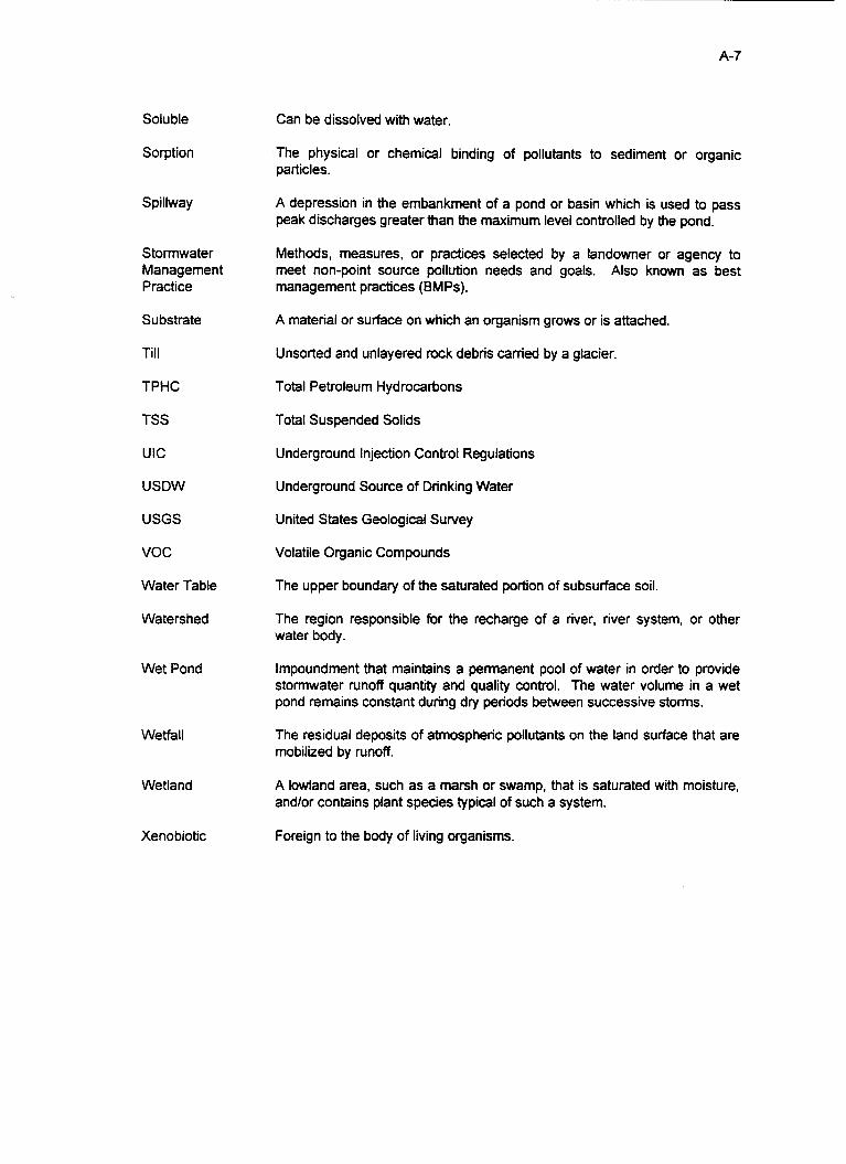
A-7
Soluble
Sorption
Spillway
Stormwater Management Practice
Substrate
Till
TPHC
TSS
UIC
USDW
USGS
voc
Water Table
Watershed
Wet Pond
Wetfall
Wetland
Xenobiotic
Can be dissolved with water.
The physical or chemical binding of pollutants to sediment or organic particles.
A depression in the embankment of a pond or basin which is used to pass peak discharges greater than the maximum level controlled by the pond.
Methods, measures, or pradices selected by a landowner or agency to meet non-point source pollution needs and goals. Also known as best management practices (BMPs).
A material or surface on which an organism grows or is attached.
Unsorted and unlayered rock debris carried by a glacier.
Total Petroleum Hydrocarbons
Total Suspended Solids
Underground Injection Control Regulations
Underground Source of Drinking Water
United States Geological Survey
Volatile Organic Compounds
The upper boundary of the saturated portion of subsurface soil.
The region responsible for the recharge of a river, river system, or other water body.
Impoundment that maintains a permanent pool of water in order to provide stormwater runoff quantity and quality control. The water volume in a wet pond remains constant during dry periods between successive storms.
The residual deposits of atmospheric pollutants on the land surface that are mobilized by runoff.
A lowland area, such as a marsh or swamp, that is saturated with moisture, and/or contains plant species typical of such a system.
Foreign to the body of living organisms.

8-1
APPENDIX B: CHARACTERISTICS OF HIGHWAY RUNOFF
B . 1 : Introduction ............................................................................................ B-2 B.2: Heavy Metals ......................................................................................... 8-2 8.3: Polyaromatic Hydrocarbons (PAH) ........................................................ 8-3 B.4: Ionic Compounds ................................................................................... 8-4 B.5: Sediment ................................................................................................ 8-4 6.6: Road Salt ............................................................................................... 8-4

6-2
B.1: Introduction:
Urbanization and highway road construction has had a profound impact on watershed hydrology. Site clearing and construction have decreased the ability of natural vegetation to intercept and detain rainfall. The construction of homes and highways has involved clearing away vegetation and grading the land evenly to allow for the construction of impervious surfaces. These actions have removed the site’s natural storage capacity. Consequently, rainfall is rapidly converted to runoff. Roadway runoff could be considered the largest contributor to non-point source pollution in urbanized America. Organics such as polyaromatic hydrocarbons (PAHs), phenols and other xenobiotic compounds in highway runoff have a significant impact on highway runoff, but it is heavy metals that constitute the greatest percentage of pollutants. Metals and organics differ by the fact that metal elements and their cations cannot be degraded into less harmful substances (69).
There are several mechanisms that result in the deposition of pollutants on the urban landscape. These mechanisms include the dryfall and wetfall of atmospheric pollutants and the direct application of road salt, fertilizers and pesticides’ normal urban activities which unintentionally contribute to pollutant volume (such as oil drippings from motor vehicles and vehicle component wear). Pollutants are also collected by stormwater running over various surfaces in the urban environment (14).
The following section provides details of some of the most common pollutants associated with stormwater runoff.
B.2: Heavy Metals:
Metals occur naturally in soil but also arise from man-made sources. The quantities of metals leaching into water from natural sources is influenced largely by the water’s pH (1 11). While most stormwater concentrations are at the pgkg (ppb) level, heavy metal amounts in the pg/g (ppm) concentration level are typically found in dry street surface sediments. (95). The metal’s dilution in stormwater is not as important as where it is ultimately deposited and collected (typically as sediment). Metals found in urban runoff are reported to be 10 to 100 times greater than concentrations (ppm) found in sanitary sewage (20). Due to the toxicity of metals, concentrations of metals found in water can have adverse effects upon public health as well as the animal and plant life (111). Heavy metals commonly found in highway runoff include: lead, zinc, iron, copper, cadmium, chromium, and nickel.
Several factors affect the level of metals in plants and soils along roadways. Some of the more important factors include: traffic volume, prevailing winds,

8-3
’ distance from source of contamination, depth in soil profile, age, and type of road; and speed of vehicles. High levels of heavy metals in soils, plants, and the atmosphere are often related to two issues: the proximity of industries and roads and to the use and/or dumping of waste materials, chemical fertilizers, and metal-containing pesticides (30).
Lead: Lead is considered a primary public concern. It has cumulative, toxic neurological effects and may be extremely harmful to children. One of the principle sources of lead in stormwater runoff was tetraethyl lead in gasoline (1 11). Sources of lead in highway runoff today include tire wear, lubricating oil and grease, and gasoline engine exhausts (53). Lead is largely particulate in nature, and forms strong complexes which are difficult to break and are persistent in the environment.
Zinc & Cadmium: With regard to human health, cadmium is the most hazardous of the metals. Cardiovascular disease has been related to inhaled and ingested doses of cadmium (29). The sources of cadmium include tire wear and insecticide application (53). Cadmium and zinc emitted from autos originates predominantly from antioxidants in lubricating oils such as Zndithiophosphate (29). Fortunately, the concentration of cadmium released by automobiles is usually low (30).
Zinc is essential for all biological functions. However, zinc is also an element which exacerbates the harmful effects of cadmium. This intensification of cadmium effects interferes with the functioning of the male reproductive system. In its pure metallic form, zinc is insoluble in water. However, in the inorganic, ionic form; zinc can enter into a biological system because it can be sufficiently water soluble (68). The main sources of zinc include tire wear, motor oil, and grease (53).
B.3: Polyaromatic Hydrocarbons (PAH):
The major source of polyaromatic hydrocarbons (PAH) is automobile tires. Hydrocarbons are common pollutants associated with the production and utilization of petroleum resources. Many microorganisms are effective degraders of hydrocarbons. Typically, PAHs are small particles of dustfall and are usually deposited within 100 meters of a highway during the winter. Only a small amount of PAH components are transported via water runoff ( c log PAHkm per vehicle per day as a mean for the whole year). The major bulk of PAH yearly load occurs during the winter and is caused by the wearing of tires. Once released, the PAHs are deposited as fine particulate dust in the snow along the highway. Therefore, snow melting represents a critical opportunity for the deposition of pollutants from roadway runoff into the environment. Large amounts of the

8-4
particulate matter containing PAH are transported to water resources with the melting snow (90).
B.4: Ionic Compounds:
Magnesium and potassium represent a significant proportion of ionic compounds associated with ‘particulate’ material. Ironically, concentrations of these two ions are generally low (c8 ppm) when compared with concentrations of sodium, calcium, chloride, and sulfate. Most major ionic constituents are found to originate from atmospheric pollution. In addition to atmospheric deposition on the road surface, rainfall can contribute up to 78% of major ionic contaminants and a maximum of 48% of suspended solids leaving the road surface in runoff (20).
B.5: Sediment:
Sediments consist largely of soil materials eroded from uplands as a result of natural processes and human activity. Sediment is one of the most significant pollutants transferred by stormwater and is an efficient carrier of toxins and trace metals (1 11).
B.6: Road Salt:
Deicing materials used to minimize ice buildup on winter roadways consist primarily of road salts in the form of sodium chloride and abrasives. A secondary source of deicing materials employed in the winter months is calcium chloride (1 11). Problems associated with the use of sodium chloride involve damage to roadside vegetation and aquatic systems that receive water from deiced roads (46).
The primary problem with road salt is the contamination of ground and surface waters which can render these drinking water sources unusable (111). High levels of sodium in drinking water can elevate blood pressure and affect kidney function in susceptible individuals. Higher levels of salt are typically detected in the summer and early autumn because rainfall volume has diminished and evapotransporation levels are high.
Roadway deicing pollution problems result from excessive salt application and improper storage. Sodium is very soluble in water and highly mobile. Aside from contaminating ground and surface water, high levels of sodium chloride can kill roadside vegetation, impair aquatic ecosystems, and corrode metal components of bridges and stormwater management devices (1 1 1).
The following is a summary of the constituents of highway runoff:

Pollutant Particulates Nitrogen, Phosphorus Heavy Metals
Source Pavement wear, vehicles, atmosphere, maintenance Atmosphere, roadside fertilizer application Leaded gasoline, tire wear, lubricating oil and grease,
bearinghrushinghrake wear, autobody rust, moving enaine Darts. insecticides
Bromide Cvanide
Exhaust Anti-cake comDound used to keeD deicina salt aranular
NaCI, CaCI, Petroleum P-chlorinated biphenyl
Rubber Asbestos
Deicing salts, grease Spills, lubricants, antifreeze and hydraulic fluids, asphalt Pesticides, atmospheric deposition, PCB catalyst in
Tire wear Clutch and brake lining wear
synthetic tires

. . . . . . ._._I _I_ ..... __I-.-- - . . . . . . . . .
c- 1
APPENDIX c: DEICING ALTERNATIVES AND SPREADING EFFICIENCY IMPROVEMENTS
C. 1 : Introduction .................................................................................... C-2 C.2: Chemical Deicing Alternatives ....................................................... C-2 C.3: Improved Spreading Efficiency ...................................................... C-3 C.4: Improved Storage Facility Management ........................................ C-4

c- 2
C.l: Introduction
Road salt is primarily composed of sodium chloride (common salt) with calcium chloride used to a lesser extent. Both lower the freezing point of the water on a road or highway, which facilitates snow or ice removal. Unfortunately, salt has the potential to impair land vegetation, water quality and aquatic ecosystems. It disrupts the uptake of potassium and other nutrients and intensifies the effects of droughts by making soil water unavailable and stunting root growth (47). There is also evidence that sodium has serious health effects (61).
Studies have found levels of chloride in waterways downstream of treated highways 31 times higher than comparative upstream samples. These levels often remained elevated through the summer (3). This is largely due to the “bare pavement” policies observed by many transportation departments nationwide. These policies call for the complete removal of snow and ice from the roadway during and after each storm.
The migration of salts is largely determined by cation exchange capacities (CEC). In the long-term, the potential of salt removal by soils having relatively high CECs is much greater than soils with low CECs. Soils with high CECs are typically clay soils. Sodium ions have a high positive charge and are naturally sorbed to such soils. Sandy soils, characterized by high permeability, allow rapid flow of water and dissolved contaminants through them and offer little column filtration prior to solution’s contact with groundwater. Though the rate and percentage of salt percolating through to groundwater varies, the average has been estimated at 35 percent for highway runoff (21).
The peak of the contamination volume level occurs during the spring thaw (21). Studies suggest that it may take more than a year to naturally flush-out most of the salt that has been applied to a watershed in the snow season. This indicates a danger of subsurface accumulation over time (104). An additional concern involves the present use of ferrocyanate in road salt mixtures for the purpose of preventing caking in the trucks. Cyanide, known best for the danger that it poses to humans, is the product of the photo-decomposition of ferrocyanate.
C.2: Chemical Deicing Alternatives
Each year, road salt used to de-ice highways costs billions of dollars in damages to vehicles, bridges and roadways. This has led to research on alternative substances and more efficient methods of application. Several options are now available which include urea and potassium chloride. Both of these alternatives to NaCl are less effective than conventional salts. A relatively promising, recent alternative to standard road salt is calcium magnesium acetate (CMA). It is less corrosive to metals, harmless to drinking water, and beneficial to some soils.

c- 3
The soil benefit arises from the fact that it contributes calcium and magnesium in exchange for metal ions which increases water and air movement (22). This same Ca and Mg exchange has been found to neutralize acid rain. Also, recent research indicates that CMA may actually inhibit the corrosion on certain steel and cast aluminum metals (21).
CMA has been proven to be an equally effective deicer as salt; but its use does have some disadvantages. It activates slower and is lighter. This produces a tendency for the chemical to be blown off its intended target area. It also readily absorbs moisture which results in a caked mass that can clog equipment (22). CMA is far less efficient than salt. For example, 2.6 tons of CMA at 25°F and 6.6 tons of CMA at 15°F are required to remove the same amount of ice from a roadway as 1 ton of salt at the respective temperatures (24). Therefore, CMA requires more trucks on the road and more return trips to the CMA stockpile (66).
Positive results after the use of CMA exist as well. When CMA was used in Massachusetts, salt contaminated wells experienced nearly a 50 percent decrease in salt levels within the first 4 years of CMA usage (97). Several reasons for its use in Massachussetts inciuded environmental damage, road damage costs, bridge degradation, auto corrosion and salt intrusion into well waters.
Even with federal funding and long-term savings, budgetary constraints in municipalities may make the use of CMA impossible. CMA is an expensive substitute for salt, nearly 23 times the cost resulting from the expensive acetic acid component (97). Fortunately, research has begun to investigate a cheaper method of acetate production (21). Furthermore, CaCI, and NaCl have many hidden costs. In one year alone, the Massachusetts Department of Public Works spent 2.5 million dollars to investigate and remediate complaints of salt contamination of wells (97). In 1976, the EPA found that salt-related damage in the United States was approximately 15 times the annual cost for salt purchase and application (45). Once these hidden costs are factored in, CMA is only 1.53 times more expensive as salt. Furthermore, CMA is now eligible for Federal Matching Funds under the Bridge Program of the lntermodal Surface Transportation Efficiency Act (ISTEA) of 1991 [See Appendix F, p. F-21. The Act provides 80 percent funding for the use of CMA on salt-sensitive bridges and in environmentally sensitive areas.
C.3: improved Spreading Efficiency
A more economically feasible option may rest in source reduction of dispensed salt. Most salting vehicles use a spinner system to cast salt and sand onto the roadway. The trucks have to drive at a slow pace, often 20-25 mph, to guarantee that a portion of the salt remains on the road. This can be dangerous because it creates a speed differential in traffic. If the vehicles drive at a faster

c- 4
pace, as much as 50 percent of the salt may leave the roadway and contaminate the roadside surface and subsurface waters (4).
Zero Velocity spreaders, designed by Tyler, Ltd@ of Minnesota, may offer a solution. The principle entails matching the speed of material exiting a spreader to the velocity of the vehicle. Maximum traveling speed can reach 45 mph and results in a salt spread that has a relative velocity of zero. The Zero Velocity system insures accuracy and stationary application with a prewetting process that adds weight to the salt or sand particles. A 110 gallon reservoir holds deicing liquid that can achieve 100% coating of projected particles. The prewetting also activates the salt, eliminating the need for the sun or tire friction to activate conventionally distributed salt.
In conventional spreaders, more than 40 percent of the salt spread on the roadway misses its target, and 30 percent can be removed by vehicle-induced turbulence. The Zero-Velocity Spreader can apply a spread in a 6-9 foot wide area with a near 100 percent accuracy. [Figure C.11 (133). The Wisconsin Department of Transportation recorded a minimum of 30 percent material savings in the winter of 1994-1995 (132). At a material cost of $30/ton, the system would pay for itself in three years (132). Furthermore, the drivers would be able to stay out longer and cover more roadways before returning to refill.
C.4: Improved Storage Facility Management
Proper storage of salt material also plays a major role in the reduction of salt degradation of water quality. Methods of salt detention include enclosed structures with roofs, overhead doors at the exit and entrance, and a method of transport that limits exposure with the use of tarps. Creating large storage facilities with the capacity to supply salt through a rough winter reduces the number of times salt must be shipped and thus reduces exposure. Placement of the salt piles is also key. Stockpiles should not be located adjacent to fresh surface water, in areas prone to flooding, high aquifer recharge areas, and in areas with steep slopes.
The improper storage of salts can have dire consequences. Surface waters near an uncovered, outdoor, sand-salt storage facility contained 13,500 ppm of salt. The MCL for sodium and chloride is 250 ppm (74).

c- 5 Figure C. 1 : Spinner Spreader Accuracy vs. Zero Velocity Spreader Accuracy
Spinner S p re ad er Zerc f e r
I I !
1 : I i
i I i i i I !
i
._--
Source: (I 33)

APPE~ D
D- 1
D: PROCESSES IN THE ENVIRONMENT
D.l: Physical Removal .................................................................................. D-2 D.2: Chemical Removal ................................................................................. D-2 D.3: Biological Removal ................................................................................ D-3

D- 2
D.l: Physical Removal:
The removal of many contaminants in runoff originating from the nation’s highways can be attained by settling. This settling is highly dependent on low water flow velocities and long detention times. Decreased fluid velocities in water pathways reduce the load capacity of the water to transfer sediments and particulate. This forces a departure from suspension and produces an accumulation at the bottom of the system. Increases in sedimentation also occur as the levels of clay found in area soils increase (51).
The size of the suspended solid determines the rate at which it settles. Suspended solids range in size from 0.005 to 100 pm in diameter. Studies have found that only 6 percent of stormwater runoff solids less than 43 pm in diameter settle while 100 percent of the sediments greater than 60 pm in diameter are removed by settling (1 24).
Two other factors that assist in settling are low turbulence and sheet flow. Turbulent flow provides upward impelling forces that resuspend particles and prevents further sedimentation (1 21). Sheet flow, as opposed to channelized flow, increases the exposed surface area, which decreases the velocrty of the runoff and reduces turbulence.
D.2: Chemical Removal:
The unsaturated or vadose zone of soil has been increasingly used as a treatment column in filtration trials. In this column, contaminants can be immobilized through the processes of sorption (the removal of a solute from the solution phase by the solid phase). A key factor in the sorption of unwanted cations such as heavy metals is ion exchange. The ion exchange is the result of the negative charge on soil colloids, clay, and organic matter. These reactions are heavily dependent on pH. At a higher pH, the attraction between the solute and the solid increases due to a greater differential between the positive and negative charges. Heavy metal ions are exchanged for sacrificial cations such as potassium and calcium (89). The measurement of this potential for ion exchange and subsequent sorption is called the cation exchange capacity (CEC).
Oxidation and reduction (redox) reactions further the removal process. When oxygen combines with many metals, particles of the product material form precipitate. The reaction causes a lowering of pH due to the abundance-of acid produced. Reduction reactions, normally occurring in anaerobic subsurface and/or submerged environments, are the opposite of oxidation reactions. Metals lose their oxygen components and settle. A negative aspect of reduction is the production of hydrogen sulfide, a foul-smelling product detected when sulfate is inhaled. Reduction decreases acid levels and thus raises pH.

D- 3
Together, oxidation/reduction reactions can remove and then concentrate, in an immobile form, pollutants that may adversely affect drinking water supplies and the environment. Adsorbed or precipitated chemicals are considered immobile in soils and sediments and biologically unavailable to plants and microorganisms. Volatilization, another process, is the loss of chemicals in vapor form from soil or liquid surfaces to the atmosphere. Evaporation is the primary mechanism of release (1 26).
Natural waterways and sediments have a natural capacity to reduce the toxicity of added metals. This natural capacity is attributed to adsorption, precipitation, and to the presence of ligands in water (126). As they enter the water, metals undergo complexation with ligands. Clay fractions contain iron and manganese oxides that provide sorption sites (54).
D.3: Biological Removal:
The ‘removal’ of pollutants, including nutrients such as nitrogen, phosphorus, and soluble metals in the aquatic environment, from a mobile system can be the result of plant uptake (89). Microbial degradation, especially of hydrocarbons in an aerobic environment, is quite effective. P seudomonas, the organisms largely responsible for hydrocarbon removal, are found in almost all soils in small quantities. They multiply when oxygen levels are high and then decrease in number in anaerobic environments. Unfortunately, pollutants are not always degraded and, upon the death of the flora, may return to the system.
The microbial decomposition of hydrocarbons is of major environmental importance (16). This may occur in aerobic or anaerobic environments. Degradation in an anaerobic environment takes longer and has a lower energy efficiency. Aliphatic and aromatic hydrocarbons are only degradable in an aerobic environment. The breakdown of hydrocarbons requires the participation of an oxygenase enzyme. Hydrocarbon organisms, in the presence of contaminated water, have been documented to increase their population by l o 3 - l o 6 fold (16). Inorganic nutrients such as nitrogen and phosphorous can be used to stimulate growth and induce remediation.
Bioaccumulation in animals must also be considered when dealing with heavy metals and pesticides. These hazardous substances are removed from the environment by living organisms. Moving up the food chain, these pollutants become concentrated in the adipose or fatty tissue of organisms. High concentrations of pesticides and metals have been found in birds and fish. Pesticide concentrations in bird tissue has resulted in sterility. Bioaccumulation should be considered a human health risk because man is at the top of the food chain.

D- 4
Contaminants adsorbed on soil particles and contaminants precipitated in soils are not available for plant uptake. Nutrients and chemicals present in pore water are available to vegetation. The presence of compounds that react with metal ions and cause precipitation or adsorption on solids will reduce the toxicity of the metals and make them less available for organisms.

. _. .
E- I
APPENDIX E: DISCUSSION OF DEVICES
E . 1 : Oil Grit Separator .................................................................................. E.2: Compost Stormwater Filter ................................................................... E.3: Wetlands ............................................................................................... E.4: Dry Detention Basins ............................................................................ E.5: Wet Detention Ponds ............................................................................ E.6: Multiple Pond Systems ......................................................................... E.7: Sand Filters ........................................................................................... E.8: Infiltration Trenches .............................................................................. E.9: Infiltration Basins .................................................................................. E.lO: Grassed Swale ................................................................................... E . 1 1 : Grass Filter Strips E . 12: Porous Pavement ...............................................................................
...............................................................................
E-2 E-6 E-I 1 E-19 E-23 E-27 E-31 E-34 E-37 E-41 E-45 E-49

E.l: Oil Grit Separators
Description:
Petroleum hydrocarbons are a major constituent of highway runoff. The set standard for these pollutants is "none detected" because they are carcinogenic and otherwise damaging to biota (107). Pseudomas and other bacteria have the potential to break these contaminants down in an aerobic environment; however, it is a slow process. The majority of oil and grease that are released from highways is sorbed to sediment and exist as particulate. This fact has led to the use of oil grit separators. An oil grit separator is a three chambered underground retention system used to remove resulting particulate and sorbed hydrocarbons. They are usually installed to catch the oil and fuel that leak from automobiles and trucks in parking lots, service stations, and loading areas (13). The maximum drainage area is approximately 2 acres which limits their use. The system is installed underground and does not present any aesthetic problems.
In a typical design, the first chamber of the three compartment system contains a permanent pool of water 3 to 4 feet deep. This chamber is responsible for the settling of grit and sediments and the trapping of floating debris [see Figure E.11. The outlet leading to the next chamber is comprised of a pair of well-screened 6 inch holes. An alternate design employed in Rockville, MD allows exfiltration to the subsoil through a series of 6 inch holes on the floor of each chamber and a layer of gravel (32). Ponding of inflow does not occur in this system.
Typically, the second chamber also holds a pool of water and is responsible for the removal of oil and grease. An inverted elbow pipe, acting as an entrance to the third chamber, traps grease and oil that are on the water's surface in the second chamber and retains these contaminants until they adsorb to sediment particles and settle. The Rockville, MD design again calls for seepage to the subsoil in the second chamber through drilled holes and a gravel layer [see Figure E.11.
The third chamber has an outlet pipe located above the floor of the compartment and experiences some pooling. This chamber is designed to remove all remaining sediment by way of settling [see Figure E.11.

Figure E. 1 : OiVGrit Separator
Side View
Stormdrain
e m Permanent Pool
01 Storagm Per Contributing Acn. 4 Feet Deep
400 CUW feet
Source: (32)
First Chamber Wand Chambor Third Chamber (Sediment Ihpping) (Oil Soparation)
Rmntorcmd Concrmte Construction
Pol I utan t Removal:
The removal of gas, oil, and other pollutants is achieved primarily through settling and sorption. The separator can catch discarded rubbish as well as hydrocarbons. Hydrocarbon removal efficiencies can range from 83 percent to almost no removal at all (83). A large storm can bring the settled contaminants back into suspension and flush them out of the system. In fact, a recent study found that sediment trappings did not increase in mass with age. The absence of an increase in trappings indicates resuspension and no actual removal. This can be very damaging to the environment due to the high levels of pollutants instantaneously released in a large storm. In 120 oillgrit separators surveyed in the early 199Os, an average of less than 2 inches of sediments were found at the bottom of each system (56). Research on removal is still limited and long term studies have not been done.
If there is a concern about high levels of oils and greases in runoff and removal is required, this easily constructed system could be used in conjunction with another system. These basins can effectively reduce maintenance of infiltration systems, detention basins, and other stormwater devices by removing such pollutants. This system is completely ineffective for all other pollutants (1 3).
costs:
According to the 1992 report, A Current Assessment of Urban BMPs, the construction of a standard three chamber system averages $7,000.00 to

E-4
$8,000.00 dollars ($10-$40 per ft3 treated). This price drops when pre-cast systems are purchased (35). The maintenance of the facility should also be considered because it must be conducted at least on a biannual basis.
Maintenance:
The separator requires regular inspection and cleaning twice a year to remove sediment, accumulated oils and grease, floatables, and other pollutants (13). A confined space entry will be required for all maintenance activities. This will add to the cost of maintenance and the number of employees required to perform maintenance.
Standard practice involves pumping water into the system and retaining the output in a tank truck. The contents are sent to a treatment plant. The pumping procedure is costly. An alternate method of maintenance requires the siphoning of each compartment of the separator and depositing the contents onto a nearby grass area. The material that remains after settling is collected and trucked to a landfill. A risk of groundwater contamination exists when land applying the pollutants. Odors have also been a noted problem.
Until the systems have been successfully cleaned out, no actual pollutant removal will be observed. Cheaper and easier methods of pollutant cleanout must be researched. Regardless of the method, the collected material should be tested occasionally to determine the proper disposal methods. If the wastes are hazardous, high disposal fees will have to be considered when analyzing cost.
... Retrofit Ca p m i b e s ;
If these systems are not maintained at least twice a year, the oil grit separators will fail to remove oils and grease from incoming runoff and may transport an even higher quantity of contaminants into natural water bodies. If a system is exhibiting failure, it can be retrofitted into a sand filter, compost filter, or infiltration trench.
Life Expectancv:
A March 1992 study found that over 95 percent of all the oil grit separators witnessed were operating as planned in the first five years of use (23); however, without continuous maintenance and inspection, the systems will fail within one year.
Safety:
Few safety risks exist due to the system’s underground location. The manhole covers providing access to the system should be locked down. A confined

E-5
space entry will be required during maintenance of these systems.
Land:
Land requirements for this system are small. It can be placed adjacent to roadways, beneath curbs, or beneath parking lots. The only requirement of this system is access to a storm drain pipe. This system is best suited for areas where space is limited and hydrocarbons are a major concern.

E- 6
E.2: Compost Stormwater Filters@
Descript ion:
The Compost Stormwater Filter (CSFIM), developed by Stormwater Management, Inc. (formerly CSFm Treatment Systems, Inc.) works on a gravity- driven principal. Stormwater flows into the unit through a scum baffle and falls into an energy dissipation device. The flow is spread onto the surface of a compost bed primarily composed of leaf compost. It is then allowed to infiltrate through to an underdrain, and finally exits. In the event that the maximum inflow capacity of 0.33 cubic feet per second (cfs) per square foot of filter surface area is exceeded, the water will pond above the compost and potentially bypass the filter bed and discharge through the outlet. The scum baffles would still serve to remove floatables, solids, and surface films [see Figure E.21.
The size of the unit varies according to peak flow from precast 6’x12’ concrete vaults to multiple 8’x18’ foot vaults and has a maximum capacity of 0.64 cfs for single units. The drop-in systems are premanufactured kits that can be outfitted with a traffic bearing lid and can be installed in a parking lot or sidewalk [see Figure E.2a]. The open unit is a larger prefabricated unit that contains multiple cells [see Figure E.2b and E.2~1. Due to sediment loading, both systems require the use of forebays and/or upstream catch basins.
The compost filter media in the system is a recycled material composed primarily of leaves taken from city streets. The leaves have already lost much of their nitrogen and phosphorus before falling. While composting for eight months, the filter material undergoes biochemical processes. After this process is completed, nearly all microbial activity stops. The resulting media has been stabilized, is odorless, has a high humic acid content, and has had its permeability characteristics increased (33). Once retired, the media can be used for landscaping, erosion control, or as a daily cover on landfills.
Another CSFW option recently developed is the CSF 1Im Radial Flow Filtration System. This system contains removable, rechargeable filter cartridges, allowing for easy maintenance. Each cartridge is designed to handle approximately 2 cfs. Incoming liquid filters though the cartridge’s CSFm media and then enters a oufflow pipe.
Negative characteristics of this system include low maximum water volumes, maintenance costs, and the fact this is a new technology with limited data available on performance. It is recommended that before a project including this system is implemented a study on this new process should be conducted. Removal rates on many pollutants are still inconclusive and long-term research does not currently exist on these space-saving devices.

E- 7
The system has been applied to large-scale use on a project in southern California. It involves a 15 mile long tollway, the San Joaquin Hills Transportation Corridor, between San Juan Capistrano and Newport Beach. The Environmental Impact Statement (EIS) required that stormwater be detained and treated to assure that increased peak flows and pollutants did not impact downstream channels. The plan called for oil/water separators. Unfortunately, to get the velocity low enough for effective treatment, the physical structure had to be very large and thus very expensive (125). Due to soil restrictions, infiltration systems, the second choice were not economically practical and the system decided on was CSFTM.
Figure E.2a: Drop-In Compost Stormwater Filter
PRLUST CONCRCTC VAULT
now SPREADCR
\ r i p
"DROP IN" CSF" UNIT - SECTION VIEW .*I
Source: (17)

E- 8
Figure E.2b: Surface Unit
PVC Panel Scum Baffle Energy Dissipator
-. ..- Drain R o c k .
Figure E.2c: Subsurface Unit
I I I /
Source: (17)
Pollutant Remo Val:
The filter itself serves four functions. It acts as a mechanical filter to remove sediments, an ion exchanger to remove ionic particles (metals) in solution, a molecular sorption site to remove organics and a biological substrate to organisms, especially bacteria, that can break down oils and grease. Removal efficiencies of 85 percent and 90 percent for oil/grease and TSS, respectively, have been reported in laboratory studies by the manufacturer.
A study conducted from 1993-1995 on an actual site showed promising results. Two urban CSFm units were monitored in Oregon. One site was located at a commercial site and the other at a Metro transfer station. The pollutant removals for iron, aluminum, copper, lead and zinc were 88, 87, 82, 100 and 89 percent, respectively. Removal of oillgrease and TSS were 83 and 46 percent, respectively (1 7).

costs:
The costs of these facilities range from a $17,000 Drop-In unit with a 0.28 cfs capacity and $75,000 for an Open Unit with a 8 cfs capacity. These costs are high when compared to conventional BMPs, but the fact that the system requires much less land area must be taken into consideration. Also note that costs are likely to vary with concrete prices and bids put forth by contractors performing the installation. The major concerns in this area are the cost of the unit and the frequency of maintenance.
Maintenance:
The surface sediments and compost must be removed and disposed of on an annual basis. Disposal is not a major issue because the EPA has classified the compost as safe sludge under EPA 503 regulations which allows disposal in unregulated landfills [Figure E.31. The open systems have a longer operation time. Open systems require compost cleanouts every two to four years and sediments removal on a yearly basis. The CSFm II has a drop-in system that can be recharged with fresh compost. Yearly removals are recommended during the dry season. Major maintenance may also be required in the event of a chemical spill or excessive sediment loading due to site erosion (17). The CSF" 11's manual recommends four inspections per year. Two inspections are for minor maintenance such as debris removal. The third determines the type of major maintenance required. The fourth inspection involves major maintenance such as back flushing and cartridge removal.
Figure E.3: Sustainable Maintenance Cycle
Source: (17)
Life Fxpectancy:
This system represents a new technology; therefore, no long term data exists on its operation. Research is recommended before this system is utilized to predict the duration of the CSF's useful functioning time.

Safety:
In regards to the open system, it is recommended that the filter be surrounded by fencing and thick vegetation. The closed system, a subsurface unit, does not present a safety hazard.
Land Reau irements:
The Compost Stormwater Filter requires a relatively small area when compared to conventional treatment BMPs. According to the manufacturer, the level of quality treatment meets or exceeds the level provided by conventional BMPs while requiring far less room for installation. The size of the unit varies according to peak flow from precast 6’x12’ concrete vaults to multiple 8’x18’ foot vaults.

E- 11
E.3: Wetlands
Definition: .
Wetlands, as defined by the US Army Corps of Engineers in 1977 (in response to the addition of Section 404 to the Clean Water Act of 1977), are:
"Those areas that are inundated or saturated by surface of groundwater at a frequency and sufficient to support, and under normal circumstances do support, a prevalence of vegetation typically adapted for life in saturated soil conditions. Wetlands generally include swamps, marshes, bogs, and similar areas."
Two basic types of constructed wetlands exist in the United States. The first is called a free water surface (FWS) wetland (or open water emergent wetland). This is similar to a natural marsh, having a soil bottom, emergent vegetation, and a water surface exposed to the atmosphere. In FWS wetlands, the bottom is carefully graded to insure uniform flow. Inlet and outlet structures insure proper distribution and control water depth [Figure E.41. The second type of constructed wetland is called a subsurface flow (SF) wetland. The length to width ratio is set at <3 for SF gravel beds and <1 for SF soil beds. Perforated PVC pipes, 4-6 inch diameter, are buried to a depth of 4-8 inch for inflow (1 19). The previously listed components found in the FWS wetland are present in the SF wetland, but the subsurface flow wetland also contains some kind of media (rock, gravel, or soil) atop the saturated layer.
The ability of natural and constructed wetlands to purify water is well documented. Increasing awareness of this and other factors led to the President establishing a no net loss system under the Clean Water Act's Section 404 (b)(l). This section directs the U.S. Army Corp of Engineers to require mitigation for most unavoidable impacts on wetlands during land development activities.
A wetland typically has a water depth of 2-8 inches. A shallow wetland is preferable for several reasons (87). A shallow water body permits the absorption of oxygen, allowing heavy metals to be oxidized and precipitated thus removing them from the water. A negative aspect of the oxidation process is the resulting decrease in pH. Lower pH may actually permit more metals to be released from insoluble forms within the sediment layer. For example, the removal of cadmium from solution increases substantially as the pH increases through its critical range of 6-8 (8).
The self-reliance of wetlands, a major economic incentive for their use, is dependent on biological processes. A key component of this method includes the renewal of nutrients through decomposition. Lower decomposition rates have been recorded in wetlands that have low pH (2.5-4.5) (86). Therefore, a maintenance of low pH could actually decrease the benefits of a wetland.

E- 12
Organic matter in the soil counteracts the drop in pH by housing bacteria undergoing oxidation reactions. If the balance is not restored, it can be artificially adjusted to neutral pH with limestone. It is preferable to allow the balance to occur naturally.
A buffer zone of 20-26 feet is recommended and should be set above the maximum water level and the DEP in New Jersey requires a 50 foot buffer [see Figure E.41. At least 75 percent of this buffer should be forested with trees and thick vegetation to repel geese, enhance nutrient uptake, reduce temperature increases through shading, and to further protect the habitat. The maximum side slope should be no greater than 11 degrees to facilitate plant growth, expand the adjacent flood zone, and address safety concerns (41).
The effective treatment area varies from 5 to 99 acres (28). Long-term discharge levels into the wetland need to be taken into account to prepare for increasing total and peak flows in an urbanizing watershed (18). Normally, stormwater wetlands consume 2-3 times the site area required by other stormwater quality options; however, they provide aesthetics and other functions not found in other conventional systems.
The irregular dimensions and shape of the system provide for a greater variety of microhabitats along the shoreline (28). The depth should vary, and there should be a large permanent pool at all times. A centrally located island would provide bird habitat and extend input to output distances by blocking the linear flow path. The average depth should remain shallow to increase the exposed surface area of the incoming runoff, promote dense vegetation, and insure safety. Earl Shaver, from the Delaware Department of Natural Resources (DNREC), has recommended that no area have a depth greater than 4 feet, 50 percent of the pond have no depth greater than one foot, 30 percent of the pond have a depth between 1 and 2 feet, and 20 percent of the pond surface have a depth between 2 and 4 feet deep (28). The deepest area of the system would be the forebay.
The preferred length to width ratio is 5 1 . The entrance of a wetland should have a forebay [see Figure E.41: a 4 ft deep retention area with a 10 percent share of the total wetland volume to trap coarse sediments and to reduce incoming velocity (28). It has been found that zinc and lead in runoff entering a wetland settled and metals sorbed to solid surfaces when detained for only 5 to 15 minutes in a forebay (49). This addition allows long-term effectiveness without maintenance for removing and assimilating runoff components. Sheet flow, resulting from riprap at the exit from the forebay, is the preferred characteristic of inflow because it increases retention time, expands surface area contact, and decreases erosion. A level spreader can be used to perform this function in larger forebays and disperses flow uniformly and thinly over the receiving area (12).

E- 13 ,
Though forebays have been demonstrated to be effective on their own when properly scaled to a wetland, investigations using a large detention pond to reduce the impacts of runoff on a constructed wetland have begun. The median lead concentrations in a 68x139-foot detention pond’s sediment was 620 ppm and only 20 ppm in the adjoining wetland. Chromium concentrations decreased from 20 ppm to 2 ppm, and zinc concentrations dropped from 250 ppm to 14 PPm (130)-
With the reductions listed above, compensatory wetlands created to replace destroyed wetlands might be an option for stormwater management. The Florida Department of Environmental Regulation (FDER) allows the regular permitting of stormwater and wastewater discharges into some wetlands as long as criteria for pretreatment of stormwater and criteria for design and performance of input facilities are met (130). The UK has also set pretreatment standards for highway runoffs destined for wetlands. These standards include grit and hydrocarbon traps and a retention facility with a minimum retention time of 30 minutes and a maximum Vout of 2.3 Ws (60).
There are many advantages to wetland use relative to other BMPs. They can be diverse in structure and can be adapted for most regions of the country. Maintenance costs are low, and they possess a wide range of side benefits. They create habitat for local animal populations and provide aesthetic qualities absent from most BMP strategies. Public access to these systems can provide an area for fishing, bird watching, wildlife observation, environmental education, nature studies, and photography. On the technical side, wetlands address erosion by providing temporary storage of water and desynchronizing peak flood flows which reduces downstream velocity and volume (1 0).
The use of wetlands as a BMP does come with certain disadvantages. These include the land requirements, which often exceed those of conventional BMPs, especially those intended to serve as quantity as well as quality control measures. Also, a wetland does not attain its full potential until planted vegetation is completely established. It may take 15 years for a carefully created forested wetland to achieve canopy closure and function at the efficiency of a natural wetland (this does not apply to emergent systems). However, long-term trends in establishment may become apparent in 2 to 3 years (44).
Constructed wetlands may contribute to thermal pollution and cause downstream warming. This problem will abate with the growth of a surrounding tree canopy. Mosquitoes can become a concern but predatory insects and the alteration of the area hydrology can be used to control populations (27). Another major disadvantage involves the lack of large scale pollutant removal in the winter months when the majority of the vegetation is not productive. Ideally, a wetland needs to be effective during all seasons for maximum pollutant removal.

E- 14
The policies regarding the use of constructed wetlands have changed in the last two decades. Compensatory wetlands were utilized as an element of stormwater containment and treatment. This practice is no longer advised. It is documented that vegetation productive in a natural ecosystem is not necessarily productive in the removal of contaminants and visa versa (63). Furthermore, stormwater wetlands differ from wetlands created to compensate for those that were destroyed because they do not replicate all of the functions of a natural wetland (35). Emulation of the natural system is not necessarily the best option because constructed systems are generally found to have a higher average removal performance than natural systems (121).
The criteria for a successful system also greatly differ between a mitigation and a water quality system. While the prosperity of a mitigation wetland may be measured by its ability to provide the biological, hydrological, and biogeochemical functions of the original wetland, the success of a wetland constructed for quantity and quality control is normally measured by its removal and storage capabilities.
The addition of pollutants to a mitigation system may cause regulatory problems. Constructed wetlands experience stresses from urban runoff that may reduce the ultimate diversity of the plant community, thereby altering the ecosystem (28). This concern is written into Special Condition C of the US Army Corps of Engineers Section 404 permit that requires constructed wetlands, when acting in a compensatory fashion, to exhibit an 80 percent success rate for planted vegetation (72). Added effluent could easily lower the success rate below the 80 percent mark and could force costly maintenance.
Authors of a study conducted by the Florida Department of Environmental Regulation (FDER) found that fewer than 50% of permitted projects could be considered successful. Of the freshwater sites, only 12% were successfully restored (65). There are common reasons for mitigation shortcomings. In the realm of planning, there exists an inability to accurately estimate or acknowledge hydroperiod, water depth, water supply, substrate, nutrient levels, and toxic compounds. Contingencies that are often mishandled include exotic plant invasions, overgrazing by herbivores, extreme meteorological events such as floods and droughts, and human impacts. System failure can also result from inadequate monitoring of maintenance needs (I 29).

E- 15
Figure E.4: Constructed Wetland
se of wetland mulch to
landscaped with native trees and schrubs for habitat
Source: (35)
Pollutant Removd:
The water quality benefits that arise from the transport through a wetlands system are the result of physical, chemical, and biological processes. Physical extraction is produced by the settling and entrapment of particulate material. Chemical removal relies on ion exchange. The biological removal is attributed to plant uptake of nutrients. Substances entering plant systems may be permanently incorporated into plant tissue such as stems, translocated back to the root at the end of the growing season, or emitted from the plant in a less harmful form.
Recent studies have shown that certain species may be much more effective in uptake. The prime source of vegetation for a proposed wetland include wetlands that have been recently destroyed for construction purposes, clogged infiltration systems, wet ponds, adjacent wetlands where applicable, and existing natural wetlands where permitted.
Criteria for the selection of suitable plants include ecological compatibility (no foreign disease risk or danger to the genetic integrity of surrounding, pristine systems), tolerance of local climate conditions, tolerance of pollutants, tolerance of a saturated substrata, ability to quickly spread and grow, and high pollutant removal capacity through direct assimilation and storage. The three most productive species, based on standing biomass, harvestable biomass

E- 16
production, seasonality of above-ground growth, tissue nutrient levels, and potential for root-zone aeration are: Zizania lafifolia (Indian Rice), Glyceria maxima (Mannagrass), and Phragmifes australis (Reed Grass) (85).
Sedimentation is the principal mechanism of contaminant removal. It results from reduced flow velocities and filtration through soils, vegetation, and decomposing litter. This process is directly related to many factors including particle size, hydrologic regime, flow velocity, residence time, storm surges, and vegetation. Vegetation is the key to reducing incoming velocity and causes the flow of incoming water to follow a path that includes many obstacles and changes in direction which eliminates a majority of the suspended particle load (87).
The availability of large underwater plant surface area is of prime importance to pollutant removal. Species such as Shoenplectus validus are likely to demonstrate high removal performance because of their high stem densities (85). They may be considered better at removal than canopy-forming, low stem-density plants such as Phragmifes australis (85).
Wetland soils are equally as important. A high organic content gives soil a high CEC, which is a direct indication of a high toxin sorption percentage. Soil capacity for heavy metals has been shown to increase with organic content (87). Winter die-outs by the vegetation replenishes this valuable biomass to the soil which substantiates the theory that wetlands are nearly maintenance free (79). The conductivity of the wetland soil is as important as the organic matter content because it is an indicator of the rate of filtration. Infiltration levels must be set at a predetermined level that will ensure ponding.
A study in 1985 by the USGS in Minnesota found that as the clay content of the soil decreased, the sedimentation rate increased (26). On the opposite end of the spectrum, if a soil type is predominantly sand, it is recommended that organic soils and/or a geotextile liner are added even though organic soils would sufficiently seal the bottom eventually (28). The sand allows quick infiltration and thus eliminates ponding and shortens detention times that are necessary for flood control and quality control. It appears that loams and silt loams are the preferable soil. When hydrocarbons are a major constituent of runoff, it may be practical to divert the flow to a sand filter. The ecological damage from the constituents might far outweigh their limited degradation by aquatic bacteria (28).
As mentioned earlier, forebays are efficient at removing pollutants before they enter the wetland system. The settling process involved is quite effective. Removal can continue at the forebay exit when a level spreader, with a minimum length of 12 feet, is employed. A level spreader is able to remove sediment and other pollutants from runoff by filtration, infiltration, sorption, and

E- 17
volatilization (1 2).
When one or several of the following factors are a concern, it may be advisable to use a subsurface flow (SF) wetland: odor, insects, public access risks, low available surface area (26). SF systems are wetlands which remain below a surface media such as rock, gravel, or soil. A 1996 research document reported that suspended solids entering a system ranging from 19 ppm to 1 154 ppm exited with an average value of 8.3 ppm resulting in an average treatment efficiency of 91.1 % (1 19).
costs:
Construction a wetland costs approximately $2,8OO/acre treated. A 1990-1 991 inventory of the EPA found that the average construction costs of the systems themselves were $22,00O/acre ($0.62/gallon) for a free water surface ( W S ) system with the surface exposed to the atmosphere and $87,00O/acre ($0.78/gallon) for a SF system with a more space-conscious subsurface retention (26). After construction, costs may be higher in the first few years of either system while establishing wetland vegetation.
Maintenance:
Maintenance can be reduced by the addition of a few measures. By setting a forebay at the entrance, sediment is kept out of the wetland and disruption of the wetland system will be minimal during cleanout. The forebay should be made of a material hard enough to allow clean outs when necessary and should have an access roadway able to support the burden of excavation equipment. In order to reduce potential work hours for upkeep, the area around the wetland should have a minimal amount of grass that gives way to larger, independent vegetation. Once a wetland is constructed, it is virtually a no-maintenance operation (1 22).
Maintenance on the wetland itself may be necessary if the system is overrun by invasive nuisance plants, a natural disaster occurs, or the system has been collecting runoff for several decades. To facilitate long-term cleanups and sediment extraction, it would be prudent to compartmentalize the wetland. With this system, a fraction may remain in operation while work is in progress. Compartmentalization will also slow water flow and increase settling (1 22).
A 24-hour dewatering pipe should be installed in preparation for wetland draining and clean-out necessitated by the event of large scale sedimentation. Depending on size, the forebay itself should be checked every 4 or 5 years to observe the percent volume of sediment storage area that has been occupied. Without the forebay for protection, the wetland will eventually lose most of its water purification properties.

E- 18
Retrofit Capab ilities;
If a wetland system fails because it becomes dry or the vegetation dies off, it can be retrofitted into a detention or retention system with minor alteration to the system.
Safety is a concern in any area where there is detained water. The use of deep water areas, such as a forebay, introduces the potential of drowning and requires both fencing and dense vegetation around the structurek perimeter. As a trespassing deterrent, dense vegetation has been proven to be more effective than fencing (28). The wetland itself, both shallow and heavily vegetated, offers little threat to human health.
Land Reau ireme-:
Wetlands can be used in contributing watersheds as small as five acres to an area as large as 99 acres and require as much as 5 percent of the total site area (23). Due to the preference for shallow, sheet flow conditions, wetlands may require 2-3 times as much space when compared to conventional stormwater quality alternatives. The system also requires a 20-26 foot buffer zone (50 foot buffer zone in New Jersey) around the maximum level of water surface elevation.

E- 19
E.4: Dry Detention Basins
Description:
Dry detention basins, also called dry detention devices and ponds, temporarily detain a portion of stormwater runoff for a specified period of time. This allows the slow release of water to reduce flooding and remove a limited amount of pollutants. The basin is usually designed as a two stage detention area. The upper stage stays dry except during large storms. The lower stage is designed specifically for pollutant entrapment and holds common, smaller storms. The released water exits through an outlet structure to a secondary treatment system or surface water [see Figure E.51. Although the quantity reduced by these processes are slight in comparison, a reduction in water quantity also occurs through infiltration and evapotranspiration (1 07).
Dry detention basins are designed to dry out between storms. However, in an effort to improve pollutant removal levels, the lower stage of the basin may be allowed to hold a permanent pool or wetland. When designing the basin, bottom soils should be examined. If soils are too permeable, there is danger to groundwater and if they are too impermeable, the dry detention pond may exhibit problems with unwanted quantities of standing water.
The pollution removal efficiency is dependent on the detention time and the percentage of annual runoff volume that is detained in the pond. Basins with short detention times do not effectively remove pollutants because the particles are not provided enough time to settle out of the runoff (127). Some studies have found that sediment at the bottom of dry detention basins are easily resuspended by the next storm event (110). Because of the many factors influencing pollutant removal, dry detention basins provide moderate but variable removal of particulate pollutants and inadequate removal of soluble pollutants (23) *
Dry detention basins are most effective in areas with a deep water table (usually several feet below the bottom of the basin). It is important that the bottom of the basin remain unsaturated during dry periods to allow for the presence of aerobic bacteria which have the potential to breakdown many highway pollutants (63). Poorly maintained dry detention basins may create nuisances and are usually unpopular with nearby residents because of mosquitoes and unsightly weed growth. Improperly located basins can degrade forests, wetlands and other habitat areas.

E- 20
Figure E.5: Extended Detention Pond
Top View
Side View I
Source: (32)
Pollutant Removal:
Settling of particulate is the most significant removal process in dry detention basins. Settling efficiency is dependent on the residence time, which is related to the volume of the detention basin. Decreasing the onfice diameter and increasing the volume of the basin will increase the residence time and the removal percentage of all pollutants present in the runoff. It has been found that rain events with profound intensity cause reduced residence time in the basin, and removal of pollutants is extremely limited in these situations. Dissolved pollutants are removed by adsorption to suspended solids which settle. Any nutrients in the runoff will be removed by biological uptake.
costs:
Dry detention basins are generally the least costly stomwater basins to construct (35). According to the Guidebook to Stormwater Best Management Practices, construction costs are estimated to be $231 O/treated acre with maintenance costs $1 OOkreated acre and $300-$5OO/maintained acre. The cost

E- 21
of obtaining permits for the construction of dry detention basins is usually less than for other stormwater quality basin options. This is due to the fact that dry detention basins have been utilized extensively for stormwater control and are well recognized by local governments (39).
Maintenance:
The maintenance of dry detention basins is both essential and costly. The routine maintenance of a dry detention basin is extremely important to the proper and effective operation of such a system. Normal maintenance costs range from 3-5% of construction costs on an annual basis (32). Primary maintenance activities include mowing, unclogging the inlet and outlet devices, and sediment removal. Due to mowing and clogging problems, the dry detention basin has the greatest routine maintenance burden of any stormwater quality basin (35).
Failure to maintain a dry detention basin will result in the inefficient removal of pollutants in stormwater runoff. Research performed on the effectiveness of dry detention basins for pollutant removal has shown that the basins will function as designed if routine maintenance is performed (48).
The primary influence causing decreased sediment trap efficiency in a dry detention basin is increased sediment on the floor of the basin. As the volume of sediment increases, increased velocities and shorter detention times decrease the efficiency of the basin to trap the inflow sediment volume. If sediment is not removed from the dry detention basin periodically, the basin will not reduce the peak discharge. Increases in peak discharge may increase the degradation of receiving waters.
Uncontrollable growth of grass and weeds will also hinder the proper functioning of dry detention basins. As the grasses grow higher, the peak discharge is decreased and the basin will be forced to detain a greater volume of water. This, in turn, may cause damage to the structure of the basin over time.
Maintenance is the key to dry detention basin efficiency. By controlling sediment accumulation and grass growth, the dry detention basin will function as designed. In addition, any debris and litter should be removed from the basin to prevent clogging of the inlet and outlet structures. Control measures such as regrading, revegetation, and riprap protection may be necessary to prevent erosion of the basin’s structures (48).
Retrofit Capab ilities :
If clogging does occur and standing water is present, the dry detention basin may be retrofitted into a wetland. The standing water will encourage the growth

E- 22
of wetland plants and will enable the basin to be transformed into a wetland system which will increase the pollutant removal rate.
Safe&:
Because the dry detention basin should remain dry between successive storm events, there is no history of safety problems associated with these facilities. If standing water appears due to clogging, then the issue of drowning would have to be addressed.
Land Requireme n&:
Depending on the size of the contributing watershed area, dry detention basins require a large volume of space to efficiently collect and store stormwater runoff. This stormwater control method is not recommended if space constraints are an issue.

E.5: Wet Detention Ponds
Description:
Wet detention ponds are impoundments that maintain a permanent pool of water to provide stormwater runoff quantity and quality control. Between successive storms, the water volume in a wet pond remains relatively constant. Excess stormwater runoff is temporarily stored in the pond until it slowly exits through an outlet structure which returns the pooled water to the original level [see Figure E.61.
The design characteristics of wet ponds dictate that a permanent pool of water remain in the pond before and after a storm event. The pond is utilized to maintain the vegetation that processes nutrients contained in the runoff during biological uptake. In addition, the settling of particulate matter that contains adsorbed contaminants, such as metals and hydrocarbons, in the still water significantly enhances water quality. Runoff that may infiltrate to groundwater will receive the additional beneffi of pollutant removal by soil bacteria and filtration.
Wet pond sediment acts as a pollutant trap, allowing a significant fraction of the pollutant loading to be permanently retained or degraded (64).
Wet ponds are most effective in areas with a high groundwater table (one that is near the bottom of the basin). During periods of little or no precipitation, a greater survival rate of wetland vegetation will be observed (39). It is important, however, that the water table extend far enough below the land surface to allow for sufficient storage space within the pond at all times. Wet ponds should be designed to allow for an extended residence period for effective pollutant removal.
A wet pond can be an attractive, aesthetic addition to any community. Wet ponds may be utilized for recreational activities, such as fishing or boating, in addition to attracting waterfowl. The creation of wetlands may be a secondary benefit to wet pond construction. If improperly sited, wet ponds can cause environmental degradation including water quality, forest, or wetland destruction and downstream warming. Large watersheds, usually greater than 10 acres, are required for wet pond operation (32).

Figure E.6: Wet Detention Pond Top View
Side View Trash Hood
seairneni roreoay (Planted as Marsh)
Source: (32)
Pollutant Removd:
Wet ponds provide moderate to high removal of soluble and particulate pollutants and are one of the most effective of all detention facilities. Pollutant removal occurs by gravitational settling, wetland plant uptake, algae settling, and decay mechanisms. Increased pollutant removal rates have been achieved by increasing the pool size in relation to the size of the contributing watershed. It has been suggested that plants should cover at least 30% of the surface of the pond with an even distribution throughout the area (64).
To achieve a high level of pollutant removal, several factors can be applied to the design of a wet pond. By installing a sediment forebay, incoming sediment is initially trapped in the forebay. This facilitates the removal of the sediment and extends the time between sediment removal in the wet pond. A wetland along the fringe or within the pond will increase sedimentation and biological uptake of pollutants (127).
costs:
Wet ponds are estimated to cost 10 to 20 percent more than conventional detention basins (35). According to the Guidebook to Stormwafer Best

E- 25
Management Practices, construction costs are estimated to be $2,80O/acre treated while maintenance costs are $112 per treated acre and $300-$500 per maintained acre (63). Permitting costs may exceed other costs associated with wet pond construction. Permits and approvals that may be required include wetland permits, water quality certifications, dam safety, sediment and erosion control plans, and waterway permits. Costs for maintaining wet ponds are estimated to be 3 to 5 percent of construction costs each year.
Maintenance:
Regular maintenance of wet ponds is essential for their effective operation. The most important type of maintenance that must be performed is the removal of sediments, which should occur every 10 to 25 years (1 16). This will minimize both the potential for metal transport through accumulated sediments and the potential contamination of groundwater. Recent research has concluded that particulate and dissolved pollutants accumulate in the loose sediments at the bottom of the pond. Accumulation of bottom sediments may affect the migration of pollutants and increase the potential for groundwater contamination (1 16). Additional maintenance that should be performed annually includes the removal of weeds, grass mowing around the pond’s perimeter, erosion control, and debris and trash removal from the inlet and outlet structures.
Retrofit Capabi -lit* res, .
Wet ponds require maintenance in the form of sediment removal every 10 to 25 years. Due to the low level of maintenance required, few ponds have failed thus far. If failure does occur, depending on the characteristics of the groundwater and soils, the wet pond can be retrofitted into a wetland system or dry detention basin.
Life Expectancy:
Recent field assessments conclude that most wet ponds are functioning as designed, with very few failures reported (35). Sediment removal must be performed to maintain the pollutant removal capability of the pond. Wet ponds are estimated to remain functional for 20 years or more.
Safety:
Public safety must be considered in the design of wet ponds. Safety problems involve drowning and the hazards associated with “off road” accidents (110). To prevent incidents, safety precautions such as fencing, warning signs, and shallow depths with gentle slopes inside the perimeter of the pond should be designed ,

E- 26
Land Requireme nts:
Wet ponds and their associated buffer zones can be 1 to 3 percent of the total site area (35). When space constraints are a consideration, wet ponds are not recommended due to a large area requirement.

E.6: Multiple Pond Systems
Description:
Multiple pond systems are an assemblage of best management practices designed to provide an optimal level of stormwater runoff treatment. This is accomplished by coordinating a treatment train consisting of runoff management techniques [see Figure E.7., E.81. Multiple pond systems consist of two or more of the following pollution control techniques: shallow wetlands, extended dry detention basins, wet ponds, or infiltration systems (35). Multiple pond systems can be designed as follows: the wet extended detention pond, extended detention wetlands, pond-marsh systems, and infiltration ponds.
The multiple pond system is a relatively new concept that has evolved over the last 5 years. These systems are not inclusive to any specific design, but can encompass a wide variety of approaches to stormwater runoff management. The approach to any multiple pond system design is site specific and should use components of the natural landscape to enhance the pollutant removal process.
The objective of a multiple pond system design is to accentuate the redundancy in treatment techniques. By combining multiple treatment methods, an improvement in the consistency and level of pollutant removal can be expected. This is due to the fact that a single method is not relied upon for pollutant removal. The use of multiple methods will increase the removal of pollutants while decreasing the pollutant load on a single treatment mechanism. In addition to increased pollutant removal, less maintenance is required (35).
Multiple pond systems are extremely flexible in their design. The designer can utilize the most effective combination of treatment methods to reflect site specific requirements. This will enable the designer to avoid negative environmental impacts that may be caused by a specific single treatment option. A treatment train that is beneficial and just as effective can be set up.
In comparison to single treatment methods, multiple pond systems have been found to provide more efficient and effective pollutant removal (35). For example, a wet pond leading to wetlands has displayed significant pollutant removal efficiencies (1 10). Apparently, the wet pond reduces the velocrty of the runoff while removing pollutants through sedimentation. The wetland then receives the runoff at a much lower velocity which enables the runoff to be evenly distributed in the system. A similar effect can be observed with a detention basin leading to a wetland. A pond with multiple cells increases pollutant removal by increasing the path of the flow and the retention time.

E- 28
Source: (35)
W Figure E.8: Enhanced Wet Extended Detention Pond
, . . . . - 4
Maximum extended - - - - - detention limit minimum (DEP)
Pond buffer, 50 R
Source: (35)

E- 29
costs:
Because the multiple pond system is a relatively new concept, information is not available on the costs associated with their construction and maintenance. Due to the expected complexity and design variations of these systems, it can be estimated that costs will be higher than conventional single treatment methods. Although routine maintenance will be required, maintenance costs can be reduced because there will be less pollutant loading on each component of the system. Additional research and information is needed to accurately represent maintenance costs.
Maintenance:
It can be expected that less maintenance will be required simply because there will be less pollutant loading on each system. Sediment removal will not be required as frequently as single treatment methods. It must also be recognized that most of the heavier particulate pollutants will be collected in the initial treatment system of the train; therefore, this component will require more frequent maintenance than the subsequent methods. To reduce time spent on maintenance, the first treatment method should have a large settling volume to accomodate sedimentation and should be easily accessible. Routine maintenance, similar to the maintenance required for dry or wet detention basins, such as mowing and debris removal, will still be necessary for the effective operation of multiple pond systems.
Retro fit Capawitres: .. .
The complex designs of multiple pond systems dictate their varied maintenance requirements. However, if maintenance is not performed as needed and the system is not maintaining efficient pollutant removal, one or more facets of the multiple pond system may fail. If failure occurs, each respective SMP in the treatment train may be retrofitted into a wetland, dry detention basin, or wet pond, with this determination depending on the characteristics of the failed system and environmental conditions.
Life Expectancy:
The life expectancy of multiple pond systems is comparable to conventional dry or wet detention facilities. However, the life expectancy can be expected to increase down the train because of decreased pollutant loading and operational requirements that will be placed on each treatment method (1 10). For example, in a wet pond and wetland system, the pond removes and traps the incoming sediment and reduces runoff velocity to extend the life of the wetland. In multiple pond systems, the inlet forebay will collect the majority of the sediment

E- 30
which can be easily removed. The remainder of the system will not need maintenance as frequently.
Safety:
When wet ponds are involved, public safety is an important consideration involved in the design of multiple pond systems. If the multiple pond system involves the use of wet ponds, safety precautions such as fencing, warning signs, gentle slopes and shallow depths inside the perimeter of the pond should be incorporated into the design to prevent accidents.
Land Requirements:
It can be expected that multiple pond systems will require a greater amount of land than conventional treatment systems. The construction of basins and wetlands will require a significant amount of land; therefore, multiple pond systems are not feasible if space restrictions exist.

E- 31
E.7: Sand Filters
Description:
Sand Filters are filtration systems that collect and gradually filter stormwater runoff, removing particulate pollutants in the process. The system is composed of a sedimentation chamber and a sand filtration chamber [see Figure E.91. The sedimentation chamber initially collects the stormwater runoff and allows the larger sand and gravel particulate matter to settle. The sedimentation chamber also reduces the velocity of the incoming runoff and gradually feeds the water into the sand filtration chamber. Lower velocity prevents any scouring of the sand. The sand filtration chamber filters the smaller pollutant-laden particulate (such as clay and silt).
The water exits the sedimentation chamber and enters the filtration unit through surface withdrawal. This prevents any sediment from becoming resuspended in the sedimentation chamber and from being transported to the filtration chamber.
Sand filters are adaptable to many conditions. They can be designed to infiltrate stormwater runoff into groundwater or to transport the water to surface waters by piping. They can be utilized with many different soil types. These systems can be designed to filter runoff from a watershed area of up to fifty acres (35).
The underground systems should not be used for an area any larger than a parking lot. For each acre of drainage area contributing stormwater to the sand filter, the pretreatment or settling chambers should be able to hold 540 ft3 of water (102). The underground version is well suited in urban areas and other sites where space is restricted.
Sand filters are appropriate in urban areas with impervious watersheds (102). They are extremely useful when limited space is available for stormwater runoff quality control. They have been recommended over the use of oil grit separators because of their high removal rates and good pollutant retention history (42).
I: Pollutant Remova
Sand filters are effective in removing particulate pollutants such as sediment and trace metals. Only low to moderate removal of soluble pollutants has been recorded. Pollutant removal occurs by settling in the sedimentation chamber, by the filtration of pollutants through the sand, and by settling on top of the sand bed in the filtration unit. The recent monitoring of sand filters in Austin, TX has

E- 32
Figure E.9: Sand Filter Design
Water level
Sedimentation chambe
organics. debris) (Heavy sediments. Filtration chamber
Screen covered with filter fabric
Source: (1 02)
displayed removal rates of 85% for sediment, 35% for nitrogen, 40% for dissolved phosphorus, 40% for fecal coliform, and 50% to 70% for trace metals (37). In addition, oils and hydrocarbons are removed by the filtration process with the majority being settled out on the top of the sand bed.
Peat, an excellent natural filter of many pollutants, has been used with sand in some urban runoff systems (42). Peat is partially carbonized vegetable matter, usually mosses, that can adsorb soluble nutrients. The peat sand filter displays the same structural design as regular sand filters except that the medium is either fabric or hemic peat alternately layered with sand. This design not only allows for excellent particulate, oil, and grease removal, but also soluble nutrient removal as well. This system is fairly new and was developed by the Metropolitan Washington Council of Governments (23).
costs:
Costs for sand filters cover a wide range according to placement and use. Costs increase significantly if the filter will be subject to vehicle loading. For example, if a sand filter will be placed under a road, the costs for design and construction will increase as the filtration unit must be structurally sound and able to withstand heavy vehicular load. If the sand filter will not be subject to vehicle loads, than a cost savings will be realized. While the current design technology is still new, a number of standard designs do exist. As stated previously, design costs will increase if concrete walls are specified for the required sand filter.
Costs are estimated to range between $3 to $10 per cubic foot of treated stormwater runoff (35) and are estimated to cost $7,850 - $26,150 per 5 acres treated. This cost is estimated to be 3 to 4 times the cost of constructing an

E- 33
infiltration trench. Maintenance costs are related to the need for sand raking, contaminated sand disposal, and debris removal. Costs are estimated to be about 5 percent of construction costs per year.
Maintenance:
Sand filters require simple and inexpensive maintenance. Maintenance is required for the sand filter to operate effectively. The sand filter should be inspected 1 to 2 times per year for operational verification. When the filtration system contains a large amount of sediment in the form of debris, particulate, and oiwgrease, the cover grates must be removed and the pollutant-laden sand removed from the system until the sand returns to its normal color and consistency. The volume of sand removed must be replaced with clean sand. The contaminated sand should be tested for content and disposed of according to applicable regulations. Recent sand filter sediment was tested, found to be non-toxic, and was landfilled. The sedimentation chamber will not require maintenance as frequently as the filtration chamber. When the maintenance is required, sediment is to be removed and dried before disposal.
Retrof t Capabiilties: .. .
I
If the sand filter fails due to clogging, the sand must be replaced with clean sand. In addition, the sand filter may be retrofitted into a compost filter because both require similar structural dimensions and designs.
Ufe Expectancy:
The oldest operating sand filter is currently 10 years old. The majority of sand filters operating today are located in the Austin, TX area, and few failures have been reported (37). The most important aspect of operating efficiencies is maintenance. If the sand filter is not maintained on an annual basis, the unit will become clogged and may overflow.
The sand filter is covered by grates and is located underground and out of view. There have been no safety problems associated with these filters.
Land Regyirements:
Sand filters require a small amount of land. This type of stormwater quality control method is recommended for projects with a restricted amount of space available for construction and use.
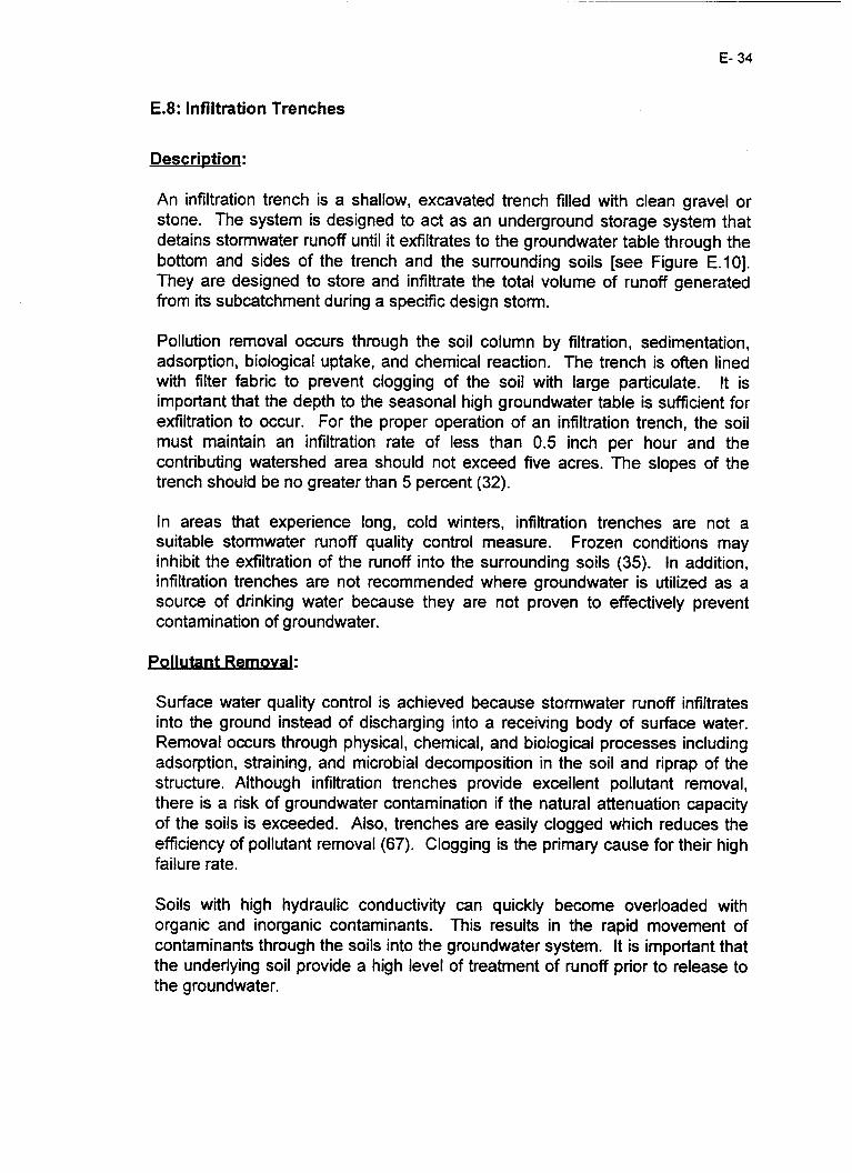
E- 34
E.8: Infiltration Trenches
Description:
An infiltration trench is a shallow, excavated trench filled with clean gravel or stone. The system is designed to act as an underground storage system that detains stormwater runoff until it exfiltrates to the groundwater table through the bottom and sides of the trench and the surrounding soils [see Figure E.101. They are designed to store and infiltrate the total volume of runoff generated from its subcatchment during a specific design storm.
Pollution removal occurs through the soil column by filtration, sedimentation, adsorption, biological uptake, and chemical reaction. The trench is often lined with filter fabric to prevent clogging of the soil with large particulate. It is important that the depth to the seasonal high groundwater table is sufficient for exfiltration to occur. For the proper operation of an infiltration trench, the soil must maintain an infiltration rate of less than 0.5 inch per hour and the contributing watershed area should not exceed five acres. The slopes of the trench should be no greater than 5 percent (32).
In areas that experience long, cold winters, infiltration trenches are not a suitable stormwater runoff quality control measure. Frozen conditions may inhibit the exfiltration of the runoff into the surrounding soils (35). In addition, infiltration trenches are not recommended where groundwater is utilized as a source of drinking water because they are not proven to effectively prevent contamination of groundwater.
Pollutant Remo Val:
Surface water quality control is achieved because stormwater runoff infiltrates into the ground instead of discharging into a receiving body of surface water. Removal occurs through physical, chemical, and biological processes including adsorption, straining, and microbial decomposition in the soil and riprap of the structure. Although infiltration trenches provide excellent pollutant removal, there is a risk of groundwater contamination if the natural attenuation capacity of the soils is exceeded. Also, trenches are easily clogged which reduces the efficiency of pollutant removal (67). Clogging is the primary cause for their high failure rate.
Soils with high hydraulic conductivity can quickly become overloaded with organic and inorganic contaminants. This results in the rapid movement of contaminants through the soils into the groundwater system. It is important that the underlying soil provide a high level of treatment of runoff prior to release to the groundwater.

Figure E.lO: Infiltration Trench Observalion Well
Emei Fgency
- I a Protcclive Layer of Filler Fabric
or Fabric Lines Sides to
Sand Filter (6-12 Fee1 Deep) or Fabric Equivalent
%Through Undisturbed Subsoils c c s with a Miniurn fc of 0.5 Inches/!4our
Source: (32)
costs:
Infiltration trenches are a cost effective option for smaller sites where large stormwater quality management techniques cannot be applied. According to the Guidebook to Stomwater Best Management Practices, construction costs are estimated to be $4/cubic foot while maintenance costs are 5%-10% of construction costs annually. Frequent maintenance requirements will increase the overall cost of the system (32). The majority of costs for permitting originate from investigations that must be conducted in the soils to determine the feasibility of an infiltration trench at a specific location. The costs for geotechnical studies at the site can be expensive. In addition, an EPA groundwater injection permit may be required.
Maintenance:
Trenches have a high removal rate if they are maintained on a regular basis. Most infiltration trenches have failed to operate because they were not maintained as required (35)(77)(78). Maintenance includes the inspection and removal of stone and gravel as needed. The fill should be cleaned on a regular basis and, if clogged, the filter fabric and liner should be replaced. The inlet structures should also be inspected for clogging. If an infiltration device

E- 36
becomes clogged, it may need to be excavated and completely rebuilt.
Retrofit Capab ilities:
Once clogging occurs, the trench will fail to operate effectively and cannot be utilized for infiltration. If this occurs, the system can be retrofitted into a sand filter, compost filter, or a dry detention basin.
Life Expectancy:
Approximately twenty percent of infiltration trenches fail to operate as designed immediately after construction and only about half of all infiltration trenches operate as designed after a few years (35). High failure rates are caused by clogging. Effective operation can be assumed for approximately five years, and regular maintenance may extend this time span. It is important to investigate the following conditions prior to construction: field verification of infiltration capacity, water table location, the use of grass swales prior to infiltration, and the use of filter fabric (32).
Because an infiltration trench is filled by stone aggregate which is located underground and out of view, there have been no direct human safety problems associated with these trenches. However, there is a concern regarding the impacts of an infiltration system on the quality of groundwater intended for human consumption. Groundwater samples taken below or downgradient from three stormwater management impoundments in Maryland exceeded primary or secondary drinking water maximum contaminant levels for aluminum, cadmium, chloride, chromium and lead (59).
Land Requirements:
Infiltration trenches require a small amount of land; therefore, this type of stormwater quality control method is recommended for projects with a restricted amount of land available for construction and use.

E- 37
E.9: Infiltration Basins
Description:
Infiltration basins are impoundments that receive and store stormwater runoff until it filtrates through the surrounding soils. They are designed to store and to infiltrate the total volume of runoff that is generated from a subcatchment during a specific design storm [see Figure E.111. Like infiltration trenches, these systems reduce the surface runoff volume, provide groundwater recharge, augment low-flow stream conditions, and reduce thermal impacts on fisheries.
Contaminant removal occurs by physical, chemical, and biological methods including filtration, adsorption, ion exchange, and biological uptake. To assist in the pollutant removal process, the addition of sediment forebays and vegetative swales to the basin system is recommended (1 10). These features will increase the removal of pollutants prior to entering the infiltration basin, preventing the basin from clogging. It is important that the depth to the seasonal high groundwater table is sufficient for exfiltration to occur. Saturation should be avoided because it is necessary to maintain aerobic conditions for microbial pollutant removal.
Soil type is an important factor for infiltration to occur successfully. Clay soils allow limited infiltration and drainage. Sandy soils allow the water to percolate quickly without proper pollutant removal. These soil conditions are a common cause of groundwater contamination (32). In a 1988 study in Arizona, 15 sites in the suwey were documented to have groundwater contamination that could be directly attributed to infiltation wells (43). Unfortunately, as many as 200 dry wells were being installed per month in the Phoenix area to meet flood control ordinances. Also raising water quality concerns, shallow groundwater is stored at depths of less than 40 feet in some areas of central Phoenix (43).
The fraction of soil organic carbon to a depth of one meter should exceed 0.3% to improve metal attenuation but should not exceed 1.5% (by weight) for hydraulic effectiveness. The siltlclay content should be reduced to 20% silt and 10% clay to improve hydraulic performance. The minimum depth to underlying unconfined aquifers should be extended to at least 9.8 feet. Furthermore, just a few centimeters of fine silt can severely degrade the performance of infiltration basins (8).
In areas that experience long, cold winters, infiltration basins are not a suitable stormwater runoff quality control measure (35). Frozen conditions may inhibit the exfiltration of the runoff into the surrounding soils. Because infiltration basins have not been proven to effectively prevent contamination of groundwater, they are not recommended where groundwater is utilized as a

E- 38
source of drinking water.
Deep infiltration systems may fall under the jurisdiction of the EPA's Underground Injection Control (UIC) regulations. The UIC program regulates the subsurface of waste fluids through underground injection wells and is intended to protect underground sources of drinking water (USDWs) from contamination.
Figure E.11: Infiltration Basin
Cross-sectional View of Embankment
Source: (32)

E- 39
Pollutant Removal:
The pollutant removal processes of infiltration basins are similar to infiltration trenches. Surface water quality control is achieved through the infiltration of stormwater runoff into the ground instead of a receiving body of surface water. When operating as designed, infiltration basins provide a high particulate pollutant removal rate and a moderate soluble pollutant removal rate. Removal occurs through physical, chemical, and biological processes including adsorption, straining, and microbial decomposition in the soils and riprap of the structure. In sandy soils, removal rates for soluble metals, chlorides, and nitrates are assumed to be quite low.
Although infiltration basins do provide excellent pollutant removal, there is a risk of groundwater contamination if the natural attenuation capaclty of the soils is exceeded as a result of large contaminant volume. Basins tend to clog easily, reducing the removal efficiency. Removal efficiency is increased by using sediment forebays and dense vegetative cover. Factors that decrease the removal efficiencies include a high water table, clay and silt soils, a large contributing watershed, and algae growth.
Soils with high hydraulic conductivity can become overloaded with organic and inorganic contaminants. This results in the rapid movement of contaminants through the soils to the groundwater system. It is important that the underlying soil provide a high level of treatment of runoff prior to release to groundwater.
costs:
Infiltration basins are estimated to cost 10%-20% more than dry detention basins (35). According to the Guidebook to Sfomwater Best Management Practices construction costs are estimated to be $2,89O/acre treated while maintenance costs are $1 15 per treated acre annually. The majority of costs for permitting originate from investigations that must be conducted in the soils and groundwater to determine if it is feasible to place an infiltration basin at a specific location. The costs for geotechnical studies at the site can be expensive. In addition, an EPA groundwater injection permit may be required.
Maintenance:
Regular maintenance is required for infiltration basins to operate effectively. Maintenance includes the inspection and removal of debris and sediment from inlet structures and forebays. Vincent Berg, the Director of Sediment and Stormwater Administration in Maryland, has stated that infiltration is "the most effective way to control stormwater, but these devices have operational problems and are prone to failure afier only several years of operation." (1 12)

E- 40
Retrofit Capabili - 'ti es, .
The main cause of failure is clogging of the soils surrounding and underlying the basin. Once an infiltration basin is clogged, failure will occur. The infiltration basin can be retrofitted into a wet pond, dry detention basin, or wetlands system.
Life Expectancv:
Approximately fifty percent of infiltration basins fail to operate as designed immediately after construction, and nearly 100 percent of infiltration basins do not function after five years of operation (35). High failure rates are due to clogging problems and can result in permanent standing water in the basin. It is important to investigate the conditions at the site prior to construction to ensure sufficient geological conditions. Studies performed to investigate basin feasibility include field verification of infiltration rates, water table location, and the use of grass swales prior to infiltration.
Safety:
Because an infiltration basin remains dry between successive storm events, there is little threat to human life. Safety may become an issue if the basin becomes clogged and there is standing water, as the standing water may entice children to swim or play in the facility and could result in drowning.
There is also a concern regarding the impact of an infiltration system on the quality of groundwater intended for human consumption. Groundwater samples taken downgradient from three stormwater management impoundments in Maryland exceeded primary or secondary drinking water maximum contaminant levels for aluminum, cadmium, chloride, chromium and lead (59). High levels of barium, copper, nickel, zinc and other chemicals were also reported in the groundwater beneath stormwater impoundments. The contaminant metals that did reach the groundwater were kept in solution because the groundwater pH was less than 5.0. It has been found that sudden large loads and high concentrations of any contaminant will percolate to groundwater (59).
hand Rea ui rements:
Depending on the size of the contributing watershed area (recommended at between two and fifteen acres), dry detention basins require a large volume of space to efficiently collect and infiltrate stormwater runoff. This stormwater control method is not recommended if space constraints are an issue.

E.lO: Grass Swales
E- 41
Description:
Grass swales are shallow gully systems composed of vegetated soils that capture and detain stormwater runoff. The pollutant removal capacity is increased when grass swaies are constructed with check dams placed periodically along the length of the concave system and across the flow path [see Figure E.12, E.131 (57). The swales have a limited capacity to convey runoff from large or intense storms and often lead into concrete lined channels or other stable stormwater control structures. The system removes pollutants by sedimentation, biological uptake, and, if the soil type permits, infiltration of runoff will also occur. In areas with a high water table, grass swales can also act as wetland systems.
When the proper vegetation is available, grass swales reduce the incoming stormwater velocity. The reduced velocity prevents the scouring and erosion of the swale structure. Side slopes of less than 5 percent are recommended for swales to effectively detain stormwater runoff and prevent erosion (63).
Check dams, normally constructed of rock, wood or hay bales, must be designed with adequate spillways, dissipater aprons, and tie-ins to the channel beds to protect the swale structure during times of high-volume runoff [Figure E. 131. Straw bales are only recommended when small storm flow volumes are expected because undercutting is common, and they are not recommended for long-term highway use because they require constant replacement.
Riprap, the assemblage of gravel and crushed stones provides a flexible lining which can adjust to foundation changes. It is also porous which allows infiltration and exfiltration of the covered soil. Potential damage to riprap can be minimized by properly designing the length, width, and depth of the rock layer. In areas where larger rock is not readily available, wire-mesh cages can be used to contain the smaller rock. The railroad tie, featured in the Schueler document [Figure E.131 is only recommended in the lowest flow areas.
As detention time in the grass swale increases, more particulate pollutants will settle out of the flow and more soluble pollutants will be used by the vegetation during biological uptake. Increased pollutant removal efficiencies have been found with grass swales that contain check dams. The effectiveness of the grass swale will depend on the site’s size, slope, and soil type. Curbs channelize the runoff and transport it at high velocities with high levels of accumulated contaminants. Areas without curbs allow for the runoff to be dispersed evenly across the vegetation at lower velocities which increases the pollutant removal rate. The velocity of flow entering the swale should be no greater than 3 feet per second to allow sufficient percolation (35). The

E- 42
vegetation should be dense, and the grass height should be higher than the water surface to increase pollutant removal and decrease flow velocity. Pollutant removal capacity increases with the increased detention time of runoff volume. In regions with sandy soils, grass swales are not recommended without soil modifications because it is difficult to maintain the small side slopes of the swale.
Figure E.12: Grass Swale
Side-doDeS
Stone Prevents Downstream Scow
Source: (32)

E- 43
Figure E.13: Check dam SPI U WA Y
EL
View Upstream
View From Above
Side View of Section A-A
- L = (3 X H)
I ?
L A
Source: (80)
Pollutant Remov&
Grass swales with check dams and low slopes exhibit high particulate pollutant removal characteristics and moderate soluble pollutant removal characteristics (1 10). Pollutant removal is the result of the filtering action of grass, sedimentation, and infiltration into the soil. Swales have proven themselves effective in removing trace metals (98). However, plant species vary in the rate and level of efficiency at which they remove pollutants. For example, reed canary grass has been determined to be effective in removing pollutants. Grasses such as bluegrass, which are intolerable to salt, are not recommended for swales receiving highway runoff.
costs: Grass swale economical and have low construction costs. According to the Guidebook to Stomwater Best Management P radices, construction costs are estimated to be $2,3OO/acre treated while maintenance costs are $92 per treated acre annually. The design should include a low slope and an area large enough to accommodate typical rainfall amounts to allow the swale to detain runoff instead of conveying it. Construction involves insuring that the proper

dimensions are excavated and seeding techniques are performed.
Maintenance:
Regular maintenance includes sediment cleanout, check dam inspection, weed control, and spot vegetation repair. Lawn mowing is also required, but the grass must be kept long enough to cover the top of the water. It is important to avert soil and grass buildup along the perimeter because this may prevent runoff from entering the swale.
Retrofit Capabi 'li ties, - .
If failure does occur because of high velocity flow and excessive vegetation, the swale can be retrofitted with check dams to increase sedimentation. If the location permits, the grass swale can be retrofitted into a grass filter strip.
Although a continuously dense grass cover is required to maintain pollutant removal efficiencies, grass swales require minimal maintenance.
There have been no safety problems associated with the presence of grass swales.
Land Reau irements;
As stated previously, grass swales usually run parallel to a road or highway either along the median, shoulders or both. Because the width of swales is not usually large, they are an ideal option for urban locations or areas in which there is not a great amount of space available for water quality control.

E.ll: Grass Filter Strips
Pescription;
Grass filter strips are typically bands of close-growing turf grass vegetation planted between highways and receiving water or another SMP facility (35). Grass is the vegetation of choice because of its dense growth, resistance to overland flow, and filtering ability (120). The design of filter strips is similar to grass swales though grass filter strips are not sloped for conveying stormwater and have much denser vegetation. The strips are strategically placed to efficiently remove both particulate and soluble pollutants from runoff originating from impervious areas [see Figure E.141. These systems, when working independently of other SMPs, can only be used for quality control and will have a minimal affect on the quantity of water discharged (1 07).
Pollutant removal occurs through sedimentation, filtration, adsorption, biological uptake, and infiltration. The incoming runoff must be in the form of low velocity (no greater than 2.5 feet per second) sheet flow in order for the filter strip to function as a stormwater quality control method (107). In areas prone to channel flow, level spreaders (usually an earthen or concrete trench situated on a contour) are recommended. If the runoff is high velocity channel flow, the filter strip can "short-circuit" and fail to operate effectively. If runoff tends to move parallel to the system, shallow berms or terraces should be constructed perpendicular to the system every 50 to 100 feet to redirect water flow. Furthermore, slope is not to exceed 15% and pollutant removal is best when systems do not exceed a 5% slope (107). The width of the system is also a crucial factor in performance and should never be of a magnitude less than 50 feet (35). For fine suspended particles, lengths of 100-300 feet may be necessary. The grass cover must remain dense and maintain a height of six to twelve inches. The average depth of runoff can never be permitted to exceed the height of the vegetation (35).
It is very important that the filter strip contains a dense vegetative cover that can resist erosion. A major problem with these systems is the establishment of weeds. Weed growth can outcompete grass and form scattered colonies of low denstty growth. This situation provides neither quantity or qualtty control. Natural succession toward a forested system should be avoided as these systems, relative to grass systems, are ineffective for water qualrty improvement (120). Adjustment of the buffer width is often the best manner by which effectiveness can be improved, as the soil's hydrologic properties are generally beyond manipulation (80). However, as the sediment trap efficiency nears loo%, a small increase efficiency will require a large addition to the buffer length (1 07).
The contributing watershed area should be small (5 acres or less) to prevent

E- 46
high velocities and channelization. Increased pollutant removal will occur when the water table is located within three feet of the filter strip, as vegetation will more effectively utilize soluble pollutants in the wet root zone.
Filter strips have many favorable attributes associated with their usage. They act as a buffer to prevent streambank erosion, are effective in protecting the riparian corridor, are aesthetically pleasing, provide groundwater recharge, and when large enough, provide a habitat for wildlife.
Figure E.14: Grass Filter Strip
Source: (32)
\ 5% smp Slope or Less
Pollutant Remo Val:
Pollutant removal actions in filter strips are similar to those in grass swales. Particulate pollutants are removed by the filtering action of the vegetation as well as the sedimentation processes. Greater removal efficiency is observed in strips containing very dense vegetation. Soluble pollutants are removed by infiltration and biological uptake in the subsoil. Filter strips have displayed effective removal of sediment, organics, and trace metals; however, the removal of soluble pollutants varies with specific site conditions.
Research has discovered that the majority of sediment deposition occurs within the first meter of the strip, until saturation occurs. The sediment then gradually

E- 47
moves past the saturated perimeter and further into the filter strip (120). The trapping efficiency was found to decrease when the vegetation was submerged under the flow. Low velocity sheet flow remains the most important specification for a high removal capacity. Efficiency is severely reduced when the flow takes on less desirable characteristics.
The costs associated with grass filter strips are relatively low. According to the Guidebook to Stomwater Best Management Practices construction costs are estimated to be $1,70O/acre for seeding and grading while maintenance costs are $50 per treated acre annually. Costs during construction include hydroseeding, grade modification, and the construction of a level spreader and berms when necessary. Costs associated with maintenance include sediment removal, replanting, reseeding, regrading and routine inspections.
Maintenance;
Filter strips fail very easily if they are not maintained regularly. Initial maintenance involves inspection of the area in the early stages of development to make sure the grass is growing quickly and is unimpeded by unwanted, competing vegetation. Continuous maintenance activities include periodic inspections, weed control, fertilization if necessary, mowing two to three times per year, regrading if channelization has occured, and reseeding (120)(107). Once the filter strip is established, maintenance will become less frequent. Long-term maintenance includes sediment removal when necessary (depending on the sediment loads). Although corrective maintenance will be required, the maintenance requirements and associated costs are comparatively low.
Retrofit Capab ilities:
During the early stages of development, high velocity flow can cause channelization, which will result in failure of the filter strips. If failure does occur, the filter strip can be retrofitted into a grass swale, detention facility, or wetlands system, depending on the characteristics of the site.
Life Expectan cv; -
Grass filter strips have a high success rate when properly designed, constructed, and maintained. Failures have occurred when the grass cover is not maintained at a high density, channelization results from uneven flow, or slopes are too large and the pollutants are not captured by the strip. To increase the life of a filter strip, the use of a level spreader is highly recommended to maintain sheet flow. There must be sediment removal to

E- 48
maintain the filtration capacity, weeding and replantirigheseeding within the first 2 years to ensure the health of the desired vegetation, and erosion control. The life expectancy of a filter strip can be indefinite.
Safety:
There have been no safety problems associated with the presence of grass filter strip.
Land Requirements:
As stated previously, grass filter strips usually run parallel to a road or highway along the shoulders. The width of the strips can be very large, which may be a major problem if land is not available.

E- 49
E.12: Porous Pavement
Description;
Porous pavement consists of a layer of porous asphalt over an underground reservoir comprised of various stones and rocks. Stormwater runoff is directed through the asphalt into a stone reservoir until it slowly infiltrates to the surrounding soil [see Figure E.151. The proper design of porous pavement is crucial to its operational effectiveness. The total design thickness must incorporate the following factors: soil support, frost penetration, and traffic load (91). In addition, the soil permeability, maximum storm intensity and frequency, allowable runoff, and slope all directly affect the reservoir capacity and must be analyzed during the design stage (91).
With the use of porous pavement, large volumes of stormwater runoff are diverted to the groundwater system. This provides for groundwater recharge and decreases runoff which has the potential to contaminating surface waters. This will decrease the chances of streambank flooding and thermal shock to aquatic species.
In addition to the positive impacts of porous pavement, there are many shortcomings to the use of this stormwater control method. There is a risk of transporting roadway contaminants, such as hydrocarbons and heavy metals, to groundwater. Contamination of groundwater can occur if the soil conditions are not conducive to adsorption and filtration functions. Porous pavement is also extremely susceptible to clogging. Depending on the concentration of contaminants and the level of runoff, the soil and asphalt can collect particulate and become clogged at a fast rate. Clogging occurs at an accelerated rate in the winter season when sand is utilized for ice prevention and removal.
Porous pavement cannot be applied where soils exhibit an infiltration rate of less than 0.5 inches per hour because the runoff may flood the reservoir (35). Conditions are optimal when there is a slope of less than 5 percent and the depth to bedrock and water table is a minimum of 3 feet from the bottom of the system (35). Because of the probable chance of clogging, porous pavement is not recommended for use on highways due to the high contaminant loading and heavy vehicular traffic.

E- 50
Figure E.15: Side-View of Porous Pavement
Course (Gravel, or Febric Layer (Urbed Soil
2 Inch Deep)
Porous Pavement Couns (2.5-10 Inches Thick) Filter Course (0.5 Inch Diameter Gravel. 1.0 Inch Thick)
Stone Reservoir
Diameter Scone) Depth Variable Dapendig on the Storage Volume Needed. Storage Provided by the Void Sp.ce Setwwn Stones
(1.5-10 Inch
Source: (32)
Pol lurn Remo Val ;
Porous pavement, when operating as designed, has exhibited high removal rates for sediment, nutrients, organic matter, and trace metals (32). Pollutant removal occurs by adsorption, filtration, and microbial decomposition. The soils below the reservoir contain aerobic bacteria that attack organics, causing their breakdown and removal. Most of the larger particles are filtered by the asphalt layer while the soils remove pollutants bound to smaller particles by all of the above processes.
costs:
Costs associated with porous pavement originate from an extensive construction and maintenance burden. Engineering and installation requirements include significant excavation and high costs for porous asphatt. Construction costs are estimated to be approximately $65,34O/acre of pavement. Maintenance costs originate from the need for quarterly vacuum sweeping and jet hosing to maintain porosity and are estimated to be $653/acre of pavement annually (63).
Maintena nce:
Porous pavement requires a great deal of maintenance. Because the pavement is prone to clogging, it is important that the pavement is vacuum swept and jet hosed on a quarterly basis to remove particulate from the system. Maintenance

E- 51
may include retrofitting the system if failure occurs.
Retrofit Capabilities:
Data from a study performed in Maryland concluded that 75 percent of porous pavement facilities have partially or totally clogged within the first 5 years of operation (70). Failure will often occur when porous pavement is not constructed or maintained properly. Clogging and reduction of porosity result from dirt and leaves settling in the porous asphalt, increased particulate material due to concentrated traffic, and ruptures in the porous surface caused by power steering of wheels in a stationary position (91). Failure has been known to occur when sand used in the winter months has clogged the porous asphalt. Once failure does occur the system can not be retrofitted in a highway environment.
Life Expecta ncv: -
Porous pavement often fails within the first 5 years of operation due to clogging. If the site is maintained as required and receives runoff with a low contaminant concentration, the pavement’s operating life may be extended.
Safety:
There have been no safety problems associated with the presence of porous pavement.
Because porous pavement is a part of the roadway and parking facilities, there are no additional land requirements.

F- 1
APPENDIX F: LEGISLATION
F . 1 : National Pollution Discharge Elimination Systems ................................ F.2: Wetland Mitigation ................................................................................. F.3: lntermodal Surface Transportation Efficiency Act (ISTEA) .................... F.4: New Jersey Wastewater Treatment Financing Program ........................ F.5: The Coastal Zone Act Reauthorization Amendments of 1990 ............... F . 6. Pineland Commission's Pinelands Coastal Management Plan ............. F.7: The Coastal Areas Facility Review Act (CAFRA) ................................... F.8: Underground Injection Control (UIC) Program ....................................... F.9: Well Head Protection ............................................................................. F.10: Stormwater Management - (N.J.A.C. 7:8-1.1 to 7:8-3.6) ..................... F . 1 1 : Environmental Impact Statement (EIS) ................................................
F-2 F-2 F-2 F-2 F-3 F-3 F-4 F-5 F-5 F-6 F-7

F- 2
F.l: National Pollution Discharge Elimination Systems (NPDES)
The 1972 amendments to the Federal Water Pollution Control Act, also called the Clean Water Act (CWA), prohibit the discharge of any pollutants to waters of the United States from a point source unless the discharge is authorized by a National Pollution Discharge Elimination Systems (NPDES) permit. On November 16, 1990, Congress amended the CWA section 402(p) to include non-point source pollution sources in the EPA's NPDES permitting process. The regulations require industries, municipalities, and transportation departments (DOTS) to obtain permits for their stormwater discharges and implement best management practices (BMPs) to control those discharges (53). In many regions, the state DOT is connected to municipal systems. Therefore, the DOT is an "interrelated discharger" and must submit a municipal permit application for any highway system serving municipalities with populations greater than or equal to 100,000. The permit includes outfall identification, best management practices, education programs, characterization of pollutants, and financial information.
F.2: Wetland Mitigation
Under the CWA Section 404(b)(l), the US Army Corps of Engineers is responsible for attaining mitigation for any unavoidable impacts on wetlands as a condition of any permit approval. The developer can be required to enhance, restore, or create wetlands on or near the development site. Mitigation projects are meant to replace, at a minimum 1:l ratio (2:l in New Jersey), the lost functions and values of natural wetlands affected by development.
F.3: intermodal Surface Transportation Efficiency Act (ISTEA)
ISTEA provides planners and decision-makers flexible funding opportunities for a wide range of surface transportation investments. Through ISTEA, states are able to use a portion of their federal funding allotment for runoff pollution control devices and other BMPs to prevent polluted runoff from reaching lakes, rivers, and bays. For example, calcium magnesium acetate (CMA) is now eligible for federal matching funds under the Bridge Program of the lntermodal Surface Transportation Efficiency Act (ISTEA) of 1991. The Act provides 80 percent funding for the use of CMA on salt-sensitive bridges and in environmentally sensitive areas.
F.4: New Jersey Wastewater Treatment Financing Program
Starting with the Fiscal Year 1997 Priority List, the Wastewater Financing Loan program has been expanded to include construction costs for non-point source pollution and stormwater management projects. The Fund provides loans at 0 percent interest for approximately 20 years for one-half of the allowable project

F-3
costs and loans at the market rate or less for the remaining allowable project costs (also for a 20 year term). Allowable projects include: construction of regional stormwater basins, extending stormwater outfall pipes, the purchase of stormwater system maintenancehon-point source management equipment, and other related activities. Loans may only be provided to units of government.
F.5: The Coastal Zone Act Reauthorization Amendments of 1990 (CZARA)
The amendments to the Coastal Zone Management Act of 1972 were passed in 1990. The new Section 6217, also known as Protecting Coastal Waters, requires the development of a manual by the USEPA entitled, “Guidance Specifying Management Measures for Sources of Non-point Pollution in Coastal Waters.” This document is designed to help 29 states with federally approved coastal zone management programs to create mandatory non-point programs. The document describes what must be contained in each state coastal non-point program and how each will be reviewed. It will help states to select appropriate management practices to control coastal NPS pollution with their respective Coastal Non-point Pollution Control Programs. These non-point source pollution programs require the approval of both the EPA and the National Oceanic and Atmospheric Administration (NOW). Once approved, Section 6217 programs can be combined with the Clean Water Act Section 319, a non-point source pollution management provision of the CWA designed to assist states in the development of non-point source controls.
Management measures expected in the state coastal non-point programs include economically achievable measures to control the addition of pollutants to our coastal waters. These should reflect the greatest degree of pollutant reductions achievable through the application of the best available non-point pollution control practices, technologies, processes, citing criteria, operational methods, or other alternatives. Because of site-specific variability within every state, accepted management practices by the EPA are not all-inclusive and do not limit the state or local agencies from using other technically sound practices. Furthermore, any stormwater discharge that is regulated by a NPDES Phase I (municipal separate storm sewers sewing populations of 100,000 or greater and for stormwater discharges associated with industrial activlty) permit is excluded from Coastal Non-point Pollution Programs.
F.6: Pineland Commission’s Pinelands Coastal Management Plan
New Jersey passed the Pinelands Protection Act in 1979 and created the Pinelands Commission to oversee the preservation of the 1.1 million acre national reserve that occupies 22 percent of New Jersey’s land area [Figure F-11. The Pinelands lie above aquifers containing 17 trillion gallons of some of the nation’s purest water (6). To achieve their goals, the Commission established the Coastal Management Plan (CMP) in January of 1981. State, county, and

F-4
municipal plans and ordinances are structured or revised to conform with this plan. As amended on August 21 of 1995, the CMP includes provisions for non- point source pollution.
Section 750-6.81 states that the CMP must protect and maintain the quality of surface and groundwater through the control of development and land use. Minimum standards for point and non-point source discharges are set in section 750-6.84. Part l(i) requires zero direct discharge into any water body. Infiltration trenches, in part 6(vi), are required to allow a minimum separation of at least two feet between the elevation of the lowest point of the bottom of the infiltration or detention facility and the seasonal high groundwater table. The Plan allows exceptions if there are other stormwater management techniques adequate to protect groundwater quality.
Section 7:50-6.87(b), requires the lining of all storage facilities that hold deicing chemicals to further protect surface and groundwater. Part (c) bans the application of herbicide to any road or public utility right-of-way within the Pinelands unless necessary for agricultural activity .
Figure F.l: Map of New Jersey’s Coastal Wetlands and Pinelands
..
Source: (131)
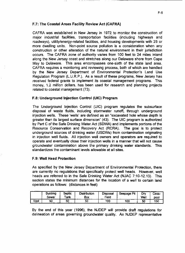
F- 5
Well
F.7: The Coastal Areas Facility Review Act (CAFRA)
Building Septic Distribution Disposal Seepage Pit Dry Cess- Sewer Tank Box Field Well pool
50 50 50 100 100 50 150
CAFRA was established in New Jersey in 1972 to monitor the construction of major industrial facilities, transportation facilities (including highways and roadways), utility/energy-related facilities, and housing developments with 25 or more dwelling units. Non-point source pollution is a consideration when any construction or other alteration of the natural environment in their jurisdiction occurs. The CAFRA zone of authority varies from 100 feet to 24 miles inland along the New Jersey coast and stretches along our Delaware shore from Cape May to Delaware. This area encompasses one-sixth of the state land area. CAFRA requires a monitoring and reviewing process, both of which are handled by the New Jersey Department of Environmental Protection’s Land Use Regulation Program (L.U.R.P.). As a result of these programs, New Jersey has received federal grants to implement its coastal management programs. This money, 1.2 million dollars, has been used for research and planning projects related to coastal management (73).
F.8: Underground Injection Control (UIC) Program
The Underground Injection Control (UIC) program regulates the subsurface disposal of waste fluids, including stormwater runoff, through underground injection wells. These ‘wells’ are defined as an “excavated hole whose depth is greater than its largest surface dimension” (43). The UIC program is authorized by Part C of the Safe Drinking Water Act (SDWA) and implements portions of the Resource Conservation and Recovery Act (RCRA). The goal is to protect underground sources of drinking water (USDWs) from contamination originating in injection well fluids. All injection well owners and operators are required to operate and eventually close their injection wells in a manner that will not cause groundwater contamination above the primary drinking water standards. This standardizes the contaminant levels allowable at all sites.
F.9: Well Head Protection
As specified by the New Jersey Department of Environmental Protection, there are currently no regulations that specifically protect well heads. However, well heads are referred to in the Safe Drinking Water Act (NJAC 7:lO-12.13). This section states the minimum distances for the location of a well to certain land operations as follows: (distances in feet)
By the end of this year (1996), the NJDEP will provide draft regulations for delineation of areas governing groundwater quality. An NJDEP representative

F-6
stated that these regulations will directly impact well heads and their protection in relation to groundwater quality.
F.10: Stormwater Management - (N.J.A.C. 7:8-1 .I to 7:8-3.6)
Purpose
The stormwater management plan implements provisions of the New Jersey Stormwater Management Act , P.L. 1981, c.32. These regulations govern stormwater pollution prevention and flood control for both undeveloped and developed watersheds. Any stormwater management plans or ordinances must comply with these regulations (N.J.A.C. 7:8-1.4). According to section 7:8-1.7, nothing in these regulations shall limit the rights of other agencies or entities from imposing stricter standards or other requirements (as allowed by statute). For example, if a stormwater management detention basin is also to be used as a soil erosion or sediment control measure under the Soil Erosion and Sediment Control Act, N.J.S.A. 4:24-39 et seq., this act and any rules enacted thereafier shall also be applicable.
Objectives
Highlights from N.J.A.C 7:8-2.1 describe the some of the objectives of the stormwater management plan:
I . To minimize increased stormwater runoff from any new land development where such runoff will increase flood damage.
2. To maintain the adequacy of existing and proposed culverts and bridges, dams, and other structures.
3. To minimize the increase in runoff pollution due to land development, which otherwise would degrade the quality of water and may render it both unfit for human consumption and detrimental to biological life.
4. To preserve and protect water supply facilities and water resources by means of controlling increased flood discharges, stream erosion, and runoff pollution.
Plannina for Stormwate r Manaaement -
N.J.A.C. 7:8-3.1 describes the planning phases of a stormwater management program. A stormwater management plan is comprised of two phases. Phase I describes preventative measures that will be applied at the site plan and subdivision review process. The purpose of Phase I is to ensure control and prevention of stormwater runoff by establishing plans and ordinances that meet the standards in these regulations for the short term.

F- 7
Phase II of the stormwater management plan will be based on a detailed analysis of alternative stormwater management approaches on a regional basis. The plan will consist of a system of non-structural and/or structural stormwater management programs to reduce flooding and non-point source pollution. Phase II analysis will include topics such as protection of environmentally crucial areas, development of plans that address appropriate remedial stormwater control measures, a survey of any institutional issues involved, and the analysis of any social, environmental, and economic implications of the proposed actions.
General Standards
The following standards, from N.J.A.C. 7:8-3.4, are guidelines that must be met and applied to major developments.
1. Flood and e rosion control : Requires that volumes are detained and rates controlled resulting in post-construction peak runoff no greater than original runoff rates for a 2-year, 1 0-year, and 100-year storm considered individually.
2. Water quality control : Detention of a small design storm is required. This storm must be either a I-year, 24 hour storm using the rainfall distribution recommended for NJ by the U.S. Soil Conservation Service or a storm of 1.25 inches of rainfall in two hours. The basin is designed to evacuate 90 percent of the drainage in approximately 18 hours for residential development and 36 hours in the case of other developments. Where soils have sufficient permeability, the production of zero runoff from the site under conditions of a 1.25 inch quality storm will be considered sufficient to meet the water quality requirement for residential development, provided that the seasonal high groundwater table does not rise to within two feet of the bottom of the detention facility. Other than residential developments, infiltration will be approved on a case by case basis to avoid groundwater pollution.
3. Mainte nance a nd repair: Responsibility for operation and maintenance of stormwater management facilities, including periodic removal and disposal of accumulated particulate material, unless assumed by a government agency, shall remain with the property owner and shall pass to any successor or owner.
F.11: Environmental Impact Statement (EIS)
Section 102(2)(c) of the National Environmental Policy Act (NEPA), passed into law in January of 1970, states that an environmental impact statement (EIS) shall be prepared for all major federal actions significantly affecting the quality of the human environment.

G- 1
APPENDIX G: PHYSIOGRAPHIC REGIONS OF THE UNITED STATES

Figure G.l: Map of the 28 Physiographic Regions Gf the United States
Summaries of 28 Physiographic Regions
Physiographic Region Description Allegheny Plateaus Hi&-level valleys with smooth slopes and an abundance of shale. Appalachian Ranges Arkansas Plateaus
Atlantic Plains
California Valley
Cascade Mountains Closed Open Basins Colorado Plateaus
Columbia Plateaus
Gulf Plains
ice Plains Klarnath Mountains Lake Plains
Missouri Plateaus New England Plateaus
ThL region is dominated by highlands interrupted by several plateaus. Fairly uniform flat surface with exceptions of minor elevation. Predominantly sand surface. Region characterized by broad open valleys, lowlands, coastal tenaces eroded to varying degrees, and northern glaciation. One of the largest structural depressions in the world. The west has a relatively steep topography while the east has a gentle slope. Largely made of volcanic rocks. Primarily basins, valleys and volcanoes. Uniform flat surface with exceptions of minor elevation. Predominantly sand surface. Highest plateaus in the United States at 1 1 ,O00 feet bordered to the north-west by the Rocky Mountain range. Gentle slopes with underlying sedimentary rock with sporadic deep canyons. Bounded by mountains on all sides except for the South. Largely low-slope plains overlying lava flows. The eastern boarder is characterized mainly by coastal terraces alternating with lowlands. The western boarder is primarily lowlands with a smaller number of coastal terraces. Tract of land with most elevations under 1OOO’ and considerable summit area. Rugged mountains rcaching 9,OOO feet in altitude. Elevations vary fiom 300’ to 1800’. This region encompasses over 1 0 million mi2 and is characterized by a vast number of landscapes. The region is resistant to erosive forces and maintains a relatively low slope. Region characterized by relatively low slopes interrupted by mountain ranges. The entire region displays the affects of glaciation.