features microcontroller application note · pdf file4 avr450 1659b–avr–11/02...
TRANSCRIPT

8-bit Microcontroller
Application Note
Rev. 1659B–AVR–11/02
AVR450: Battery Charger for SLA, NiCd, NiMH and Li-Ion Batteries
Features• Complete Battery Charger Design• Modular “C” Source Code and Extremely Compact Assembly Code• Low Cost• Supports Most Common Battery Types• Fast Charging Algorithm• High Accuracy Measurement with 10-bit A/D Converter• Optional Serial Interface• Easy Change of Charge Parameters• EEPROM for Storage of Battery Characteristics
DescriptionThe battery charger reference design is a battery charger that fully implements the lat-est technology in battery charger designs. The charger can fast-charge all popularbattery types without any hardware modifications. It allows a full product range ofchargers to be built around a single hardware design; a new charger model isdesigned simply by reprogramming the desired charge algorithm into the microcon-troller using In-System Programmable Flash memory. This allows minimum time tomarket for new products and eliminates the need to stock more than one version ofthe hardware. The charger design contains complete libraries for SLA, NiCd, NiMH,and Li-Ion batteries.
Figure 1. Battery Charger Reference Design Board
1

The battery charger reference design includes two battery chargers built with the high-end AT90S4433 microcontroller and the highly integrated low-cost 8-pin ATtiny15microcontroller. However, it can be implemented using any AVR microcontroller withA/D converter, PWM output and enough program memory to store the desired chargingalgorithm.
Introduction As more and more electronic equipment becomes portable, the rush for better batterieswith higher capacity, smaller size and lower weight will increase. The continuingimprovements in battery technology calls for more sophisticated charging algorithms toensure fast and secure charging. Higher accuracy monitoring of the charge process isrequired to minimize charge time and utilize maximum capacity of the battery whileavoiding battery damage. The AVR microcontrollers are one step ahead of the competi-tion, proving perfect for the next generation of chargers.
The Atmel AVR microcontroller is the most efficient 8-bit RISC microcontroller in themarket today that offers Flash, EEPROM, and 10 bits A/D converter in one chip. Flashprogram memory eliminates the need to stock microcontrollers with multiple softwareversions. Flash can be efficiently programmed in production just before shipping the fin-ished product. Programming after mounting is made possible through fast In-SystemProgramming (ISP), allowing up-to-date software and last minute modifications.
The EEPROM data memory can be used for storing calibration data and battery charac-teristics, it also allows charging history to be permanently recorded, allowing the chargerto optimize for improved battery capacity. The integrated 10-bit A/D converter givessuperior resolution for the battery measurements compared to other microcontroller-based solutions. Improved resolution allows charging to continue closer to the maximumcapacity of the battery. Improved resolution also eliminates the need for external op-amps to “window” the voltage. The result is reduced board space and lower systemcost.
AVR is the only 8-bit microcontroller designed for high-level languages like “C”. The ref-erence design for AT90S4433 is written entirely in “C”, demonstrating the superiorsimplicity of software design in high-level languages. C-code makes this referencedesign easy to adopt and modify for today’s and tomorrows batteries. The referencedesign for ATtiny15 is written in assembly to achieve maximum code density.
2 AVR450 1659B–AVR–11/02

AVR450
Theory of Operation The charging of a battery is made possible by a reversible chemical reaction thatrestores energy in a chemical system. Depending on the chemicals used, the battery willhave certain characteristics. When designing a charger, a detailed knowledge of thesecharacteristics is required to avoid damage inflicted by overcharging.
The AVR 8-bit RISC MCU The reference designs includes two separate battery chargers. One using AT90S4433AVR microcontroller and one using the ATtiny15 AVR microcontroller. The AT90S4433design demonstrates how efficient a battery charger can be implemented with C-code.The ATtiny15 design shows the highest integrated and lowest cost battery charger avail-able in today’s market. The AT90S4433 can be used for voltage and temperaturemonitoring with UART interface to PC for data logging. Table 1 shows the differences inthe design.
Battery Technologies Modern consumer electronics use mainly four different types of rechargeable batteries:
• Sealed Lead Acid (SLA)
• Nickel Cadmium (NiCd)
• Nickel Metal Hydride (NiMH)
• Lithium-Ion (Li-Ion)
It is important to have some background information on these batteries to be able toselect the right battery and charging algorithm for the application.
Sealed Lead Acid (SLA) Sealed Lead Acid batteries are used in many applications where cost is more importantthan space and weight, typically preferred as backup batteries for UPS and alarm-sys-tems. The SLA batteries are charged using constant voltage, with a current limiter toavoid overheating in the initial stage of the charging process. SLA batteries can becharged infinitely, as long at the cell voltage never exceeds the manufacturer specifica-tions (typically 2.2V).
Nickel Cadmium (NiCd) Nickel Cadmium batteries are widely used today. They are relatively cheap and conve-nient to use. A typical NiCd cell can be fully charged up to 1,000 times. They have a highself-discharge rate. NiCd batteries are damaged from being reversed, and the first cellto discharge completely in a battery pack will be reversed. To avoid damaging dischargeof a battery pack, the voltage should be constantly monitored and the application shouldbe shutdown when the cell voltage drops below 1.0V. NiCd batteries are charged withconstant current.
Table 1. Design Differences
AT90S4433 Design ATtiny15 Design
Programming Language C Assembly
Code Size (approximately) 1.5K Bytes <350 Bytes
Current Measurement External Op-Amp Gain Stage Built-in Differential Gain Stage
PWM Frequency 14 kHz, 8-bit Resolution 100 kHz, 8-bit Resolution
Clock Source External Crystal, 7.3 MHz Internal Calibrated RC Oscillator, 1.6 MHz
Serial Comm. Interface Yes No
In-System Programming Yes Yes
31659B–AVR–11/02
Nickel Metal Hydride (NiMH) Nickel Metal Hydride batteries are the most widely used battery type in new lightweightportable applications (i.e., cell phones, camcorders, etc.). They have a higher energydensity than NiCd. NiMH batteries are damaged from overcharging. It is thereforeimportant to do accurate measurements to terminate the charging at exactly the righttime (i.e., fully charge the battery without overcharging). Like NiCd, NiMH batteries aredamaged from being reversed.
NiMH has a self-discharge rate of approximately 20%/ month. Like NiCd batteries, NiMHbatteries are charged with constant current.
Lithium-Ion (Li-Ion) Lithium-Ion batteries have the highest energy/weight and energy/space ratio comparedto the other batteries in this application note. Li-Ion batteries are charged usingconstant voltage, with current limiter to avoid overheating in the initial stage of thecharging process. The charging is terminated when the charging current drops belowthe lower current limit set by the manufacturer. The battery takes damage from over-charging and may explode when overcharged.
Safe Charging of Batteries
Modern fast chargers (i.e., battery fully charged in less than three hours, normally onehour) requires accurate measurements of the cell voltage, charging current and batterytemperature in order to fully charge the battery completely without overcharging or oth-erwise damage it.
Charge Methods SLA and Li-Ion batteries are charged with constant voltage (current limited). NiCd andNiMH batteries are charged with constant current and have a set of different terminationmethods.
Maximum Charge Current The maximum charge current is dependent on the battery capacity (C). The maximumcharge current is normally given in amounts of the battery capacity. For example, a bat-tery with a cell capacity of 750 mAh charged with a charging current of 750 mA isreferred to as being charged at 1C (1 times the battery capacity). If the charging currentfor trickle-charge is set to be C/40 the charging current is the cell capacity divided by 40.
Overheating By transferring electric energy into a battery, the battery is charged. This energy isstored in a chemical process. But not all the electrical energy applied to the battery istransformed into the battery as chemical energy. Some of the electrical energy ends upas thermal energy, heating up the battery. When the battery is fully charged, all the elec-trical energy applied to the battery ends up as thermal energy. On a fast charger, thiswill rapidly heat up the battery, inflicting damage to the battery if the charging is not ter-minated. Monitoring the temperature to terminate the charging is an important factor indesigning a good battery charger.
4 AVR450 1659B–AVR–11/02

AVR450
Termination Methods The application and environment where the battery is used sets limitations on the choiceof termination method. Sometimes it might be impractical to measure the temperature ofthe battery and easier to measure the voltage, or the other way around. This referencedesign implements the use of voltage drop (-dV/dt) as primary termination method, withtemperature and absolute voltage as backup. But the hardware supports all of the belowmentioned methods.
t – Time This is one of the simplest ways to measure when to terminate the charging. Normallyused as backup termination when fast-charging. Also used as primary terminationmethod in normal charging (14 - 16h). Applies to all batteries.
V – Voltage Charging is terminated when the voltage rises above a preset upper limit. Used in com-bination with constant current charging. Maximum current is determined by the battery,usually 1C as described above. Current limiting is crucial to avoid thermal damage tothe battery if charge current is too high. SLA batteries are normally charged infinitely bysetting the maximum voltage above the actual charge voltage. Used for Li-Ion as pri-mary charging algorithm/termination method. Li-Ion chargers usually continue with asecond phase after the maximum voltage has been reached to safely charge the batteryto 100%. Also used on NiCd and NiMH as backup termination.
-dV/dt – Voltage Drop This termination method utilizes the negative derivative of voltage over time, monitoringthe voltage drop occurring in some battery types if charging is continued after the bat-tery is fully charged. Commonly used with constant current charging. Applies to fast-charging of NiCd and NiMH batteries.
I – Current Charging is terminated when the charge current drops below a preset value. Commonlyused with constant voltage charging. Applies to SLA and Li-Ion to terminate the top-offcharge phase usually following the fast-charge phase.
T – Temperature Absolute temperature can be used as termination (for NiCd and NiMH batteries), but ispreferred as backup termination method only. Charging of all batteries should be termi-nated if the temperature rises above the operating temperature limit set by themanufacturer. Also used as a backup method to abort charging if voltage drops below asafe temperature – Applies to all batteries.
dT/dt – Temperature Rise The derivative of temperature over time can be used as termination method when fast-charging. Refer to the manufacturer’s specifications on information on the exact termi-nation point (Typically 1C/min for NiCd batteries) – Applies to NiCd and NiMH.
DT – Temperature over Ambient Temperature
Terminates charging when the difference between ambient (room) temperature and bat-tery temperature rises over a preset threshold level. Applies to NiCd and SLA as primaryor backup termination method. Preferred over absolute temperature to avoid batterydamage when charged in a cold environment. As most systems have only one tempera-ture probe available, the ambient temperature is usually measured before charging isinitiated.
dV/dt = 0 – Zero Delta Voltage This termination method is very similar to the -dV/dt method, but pinpoints more accu-rately when the time voltage no longer rises. Applies to NiCd and NiMH batteries.
51659B–AVR–11/02

Hardware Implementation
The reference design includes two complete battery charger designs. The referencedesign is divided in 5 main blocks (see Figure 2).
Figure 2. The Main Blocks of the Battery Charger Reference Design
Power Supply Includes analog reference, push-button and LEDs. The input voltage is rectified throughD9 - D12 and then filtered by C13. The rectified input voltage can be measured at thetestpoint marked “VIN”. VIN is supplied to both the buck converter and to the LM7805voltage regulator. The LM7805 delivers 5V for the microcontrollers. This voltage can bemeasured at the testpoint marked “VCC” The LED marked “5V OK” indicates power on.
PC Interface Connected to the UART interface on the AT90S4433. Can be used to interface PC forlogging battery data during charging. The data can be imported in a spreadsheet to dis-play the charging characteristic for a battery. The AT90S4433 can also be used as datalogger when using the ATtiny15 battery charger.
LEDs and Switches The board has several LEDs and switches for debug/monitoring purpose. Only few areused in the current applications, but the rest can be added easily when need.
• LED0: Connected to Port B, pin 0 on AT90S4433. Used in the current application for visualizing the charge mode fast or trickle.
• LED1: Connected to Port B, pin 2 on AT90S4433.
• LED2: Connected to Port B, pin 3 on AT90S4433.
• LED3: Connected to Port B, pin 0 on the AT90S4433. Used to display “Error” in the AT90S4433 application.
• LED4: Not connected, can be connected to test points on the board for extended debug/monitoring.
• LED5: Not connected, can be connected to test points on the board for extended debug/monitoring.
tiny15 BatteryCharger2333
BatteryCharger
PowerSupply
LEDs and SwitchesPC Interface
6 AVR450 1659B–AVR–11/02

AVR450
• LED6: Connected to Port B, pin 1 on ATtiny15. Used In the current application for visualizing the PWM frequency.
• VCCPower: Indicates power status.
• SW0: Connected to Port D, pin 4 on AT90S4433. Used to start the charger in the current AT90S4433 application.
• SW1: Connected to Port D, pin 5 on AT90S4433.
• SW2: Connected to Port D, pin 6 on AT90S4433.
• SW3: Connected to Port D, pin 7 on AT90S4433.
• RESET: Restarts the program and is used to recover from charge errors.
In-System Programming (ISP) Interface
Both designs have a 10-pin ISP header on the test board. The Flash program memoryand EEPROM data memory can be downloaded from AVRISP PC programmingsoftware.
ATtiny15 with 100 kHz Buck Converter
ATtiny15 includes special features to make it specially suited for battery charger appli-cations. The internal 100 kHz PWM is connected to a buck converter. The highswitching frequency and high accuracy reduce the size of the external coil and capaci-tors. Testpoints are added to easily monitor the PWM output, voltage input, and currentinput. The ATtiny15 includes an internal gain stage that can amplify the differential volt-age between two A/D channels. This eliminates the need for external op-amps. Thecharge current is measured as the differential between two A/D channels over a 0.25�resistor. Power supply for the battery charger is shown in Appendix 2.
AT90S4433 with 14 kHz Buck Converter
The 90S4433 battery charger design uses an external op-amps to amplify the voltagefor the current measurement. This ensures the highest accuracy for the battery mea-surement. The charger is capable of communicating with a PC, which can be used tomonitor charging parameters and to debug the charging algorithm.
The battery charger circuit was designed to charge any of the four battery types SLA,NiCd, NiMH and Li-Ion with the appropriate charge algorithm. These charge algorithmsinclude fast-charge mode and a top-off trickle-charge to gain minimum charge time withmaximum battery capacity. Power supply for the battery charger is shown inAppendix 2.
Buck Converter The buck-converter is similar for both the AT90S4433 and the ATtiny15. They consist ofone P-channel MOSFET switching transistor driven by the AVR via one bipolar NPNtransistor. The switching transistor is connected to an inductor, a diode and a capacitor(see Figure 3). An additional diode prevents the battery from supplying voltage into themicrocontroller when the power is disconnected. When the switching transistor is on(illustrated by a switch on the figures below) the current will flow like Figure 3A illus-trates. The capacitor is charged from the input via the inductor (the inductor is alsocharged up). When the switch is opened (Figure 3B), the inductor will try to maintain itscurrent-flow by inducing a voltage. The current flows through the diode and the inductorwill charge the capacitor. Then the cycle repeats itself. If the duty cycle is decreased, byshorter on time, longer off time, the voltage will decrease. If the duty cycle is increased(longer on timer, shorter off time), the voltage will increase. The buck-converter is mostefficient running on a duty cycle of 50%.
71659B–AVR–11/02

Figure 3. Buck Converter Switching Principle
Voltage Reference The voltage reference is supplied by a TL431 CPK voltage reference. AREF is set by theresistors R34 and R10 and can be calculated by:
This value is a trade-off between a high-resolution (low AREF value) and a high signal-to-noise ratio (high AREF value). The voltage reference is common for both battery chargerdesigns
Battery Temperature Temperature is measured by a negative temperature coefficient (NTC) resistor. It hasan approximate resistance of 10 k� at 25�C. The NTC is part of a voltage divider, whichis powered by the reference voltage.
The resolution in respect to the voltage measured across the NTC is the same as for thevoltage measurement circuit.
Resolution:
The steps can be calculated by the following equation:
The NTC resistance does not follow a linear curve, which makes it difficult to calculatethe temperature from the ADC value. Using a table to look up the temperature solvesthis (see Table 2). The table indicates the steps equal to 0.5�C for ADC values 400 to675. ADC value 400 is approximately 37�C and 675 is 8.6�C. Using this table and doingsome minor changes in the header file B_DEF.H will make it easy to implement anyNTC resistor. The ATtiny15 battery charger design assumes that the linearity of the ther-mistor is sufficient to detect a temperature increase. Therefore, it uses a constantcompare value to monitor the temperature.
The values in the table are calculated from the voltage divider at the NTC and datasheetfor the NTC.
V VSWITCH OFFSWITCH ON
GND GNDGND
CAPACITOR CAPACITORDIODESHOTTKY
DIODESHOTTKY
INDUCTORINDUCTOR
(A) (B)
IN VINOUT V
GND
OUT
V3.67K10
7K412.495
R
R1VA
10
34REFREF ���
�
����
����
��
����
���
stepmV
stepsV
58.31024
67.3�
����
kR
RN
NTC
NTC
101024
8 AVR450 1659B–AVR–11/02

AVR450
AT90S4433 Battery Charger
This section describes theory specific for the battery charger design based onAT90S4433.
Parameters for Layout Oscillator frequency: fOSC = 7.3728 MHz
Saturation voltage: Vsat = 0.5V
Input voltage: VI = 15V
Output voltage: VO = 1.5V
Maximum output current: IO,max = 1.5A
8-bit PWM:
With duty cycle of 50%:
Inductance:
Table 2. NTC Steps According to Temperature
ADC Reading Tempereature (�C) 0.5�C Steps NTC (�) Resistance
675 8.6 5 19341
650 11 4 17380
625 14 6 15664
600 16 5 14151
575 18.8 5 12806
550 21.2 5 11603
525 23.6 5 10521
500 26.2 5 9542
475 28.8 4 8652
450 32 6 7840
425 34 4 7095
400 37 5 6410
375 39.4 5 5778
sf
TOSC
��� 199.69510
ss
ton ���
� 60.342
199.69
� � � � HA
sVVVI
tVVVL
o
onsatI�
� 9.1495.12
60.345.15.0152 max,
0�
�
��
�
��
�
91659B–AVR–11/02

This gives a duty cycle of
AT90S4433 Measurement Circuitry
Battery Voltage The charging voltage is monitored using an op-amp to measure the voltage differencebetween the positive and the negative pole of the battery. In order to select a suitablemeasurement range for the charger, decide how many battery cells and what type ofbatteries to charge, select a suitable input voltage (V1 - V2) and scale resistors for thevoltage measurement. The op-amp circuit for measuring the battery voltage is an ordi-nary differential op-amp circuit. The equation for the output voltage from the op-ampcircuit is shown below. The ADC is capable of measuring the voltage range from AGND toAREF (3.67V). The output voltage (VBAT2) from the op-amp has to be within this range:.
Where:
• VBAT2 is the output voltage from the op-amp to the AVR A/D.
• V1 is the positive pole of the battery.
• V2 is the negative pole of the battery.
• Ra and Rb are the resistors in the resistor network used to set the gain for the op-amp.
• Ra is equal to R10 and R12.
• Rb is equal to R6 and R7.
The maximum charge voltage will be:
Gain in op-amp:
sVVV
AHVVV
ILt
OsatI
Oon ��
��
���
��
��
� 83.335.12.015
31502max
%9.48489.0199.6983.33
���
ss
Tton
�
�
� �21*2 VVRbRa
VBAT ��
Vkk
ARaRb
VV REF 1.1267.3*1033
*)21( ��
����
303.03310
1 ��
���
kk
RbRaG BU
10 AVR450 1659B–AVR–11/02

AVR450
The resulting battery measurement resolution:
Charge Current The charge current is measured by sensing the voltage over a 0.033� shunt-resis-tor(R1). This voltage is amplified using an op-amp to improve the accuracy of themeasurement before it is fed into the A/D converter.
This voltage is amplified by the factor:
The op-amp output voltage is therefore:
which is:
The maximum current that can be measured is:
This gives a resolution of:
The step number for a given current can now be calculated from:
The current from a certain step number is:
stepmVmV
GionADCresolut
BU82.11
303.058.3
1��
4.5868039
112
5�
�
����
kR
R
62
52 1 RI
RR
V ShuntIbat �����
����
��
ShuntIbat IV �� 926.12
AIBAT 0.2926.158.3
max ��
stepmA
stepsmA
95.110242000
�
stepmA
NIShunt 95.1��
stepmA
IN Shunt
95.1�
111659B–AVR–11/02

ATtiny15 Battery Charger This section describes theory specific for the battery charger design based on ATtiny15.The 25.6 MHz oscillator frequency is generated with an on-chip PLL from an 1.6 MHzinternal RC-oscillator. The reference design is shipped without resistors for dividingdown the voltage of the battery. This limits the maximum voltage to 3.67V, making itsuitable for 1-2 cells NiCd or NiMh batteries. To use higher voltages, simply add therequired resistors to divide down the voltage into the 0-3.67V range. Calculation of theresistors are described at the end of this section.
Parameters for Layout Oscillator frequency: fOSC = 25.6 MHz
Saturation voltage: Vsat = 0.5V
Input voltage: VI = 12V
Output voltage: VO = 1.5V
Maximum output current: IO,max = 1.5A
8-bit PWM:
With duty cycle of 50%:
Inductance:
This gives a duty cycle of
Sf
TOSC
��� 96.9255
Ss
t on ���
� 43.42
96.9
� � � �H
AsVVV
ItVVV
Lo
onsatI��
�
����
��� 1.21
5.1243.45.15.015
2 max,
0
SVVV
AHVVV
ILt
OsatI
Oon ��
��
���
��
��
� 88.45.15.015
3222max
%9.44449.096.988.4
���
��
ss
T
ton
12 AVR450 1659B–AVR–11/02

AVR450
ATtiny15 Measurement Circuitry
Battery Voltage The charge voltage is measured directly on the positive battery pole. When a voltagehigher than the reference voltage (3.67V) is used to charge the battery, the chargingvoltage can be divided down with two resistors to fit into the 0-3.67V area. This input isalso the negative input for the differential measurement of the battery charge current asshown in Figure 4. The current is measured as the difference between the negative andpositive input to the internal 20x gain stage. This voltage is measured over a 0.25�shunt resistor.
All measurements are done with 10-bit (1024 steps) resolution.
Figure 4. Voltage and Current Measurement
The voltage resolution is decided by AREF.
Resolution:
In order to select a suitable measurement range for the charger, decide how many bat-tery cells and what type of batteries to charge. The ADC is capable of measuring thevoltage range from AGND to AREF (3.67V). The output voltage (VADC) from the voltagedivider has to be within this range.
Where:
• VADC is the output voltage from the voltage divider to the AVR A/D.
• Vb is the battery voltage.
• Ra and Rb are the resistors used to scale down the battery voltage.
• Ra is equal to R8 in the reference design.
• Rb is equal to R16 in the reference design
Note that the resistors R9 and R17 for scaling down the voltage of the shunt resistorsmust be equal to R8 and R16 for scaling down the voltage measurement. The referencedesign uses R8 = R9 = 3.7 k� and R16 = R17 = 2.2 k�.
Sense Resistor
ADC3 VBAT
ADC2
I BAT20xGainStage
tiny15
stepmV
stepsV
58.31024
67.3�
� �VbRbRa
RbVADC *
�
�
131659B–AVR–11/02

This gives maximum charge voltage:
Charge Current The charge current is measured by sensing the voltage over 0.025� shunt-resistor. Thisvoltage is amplified 20 times using the internal gain stage to improve the accuracy of themeasurement before it is fed into the A/D converter.
The ADC input voltage output voltage is:
where:
• VIbat is the analog input voltage to the A/D converter.
• Ishunt is the current through the 0.25� shunt resistor.
• Ra and Rb are the resistors used to scale down the voltage on the shunt resistor with the same scale as the voltage measurement.
• Ra is equal to R9.
• Rb is equal to R17
The maximum current that can be measured is:
This gives a resolution of:
The step number for a given current can now be calculated from:
The current from a certain step number is:
Vbat 1R8
R16---------+
� �� �VADC 1 3.7
2.2--------+
� �� �3.67 9.8V= = =
1820 RIRR
RV shunt
AB
BIbat ���
��
����
�
�
shuntIbat IV �� 864.1
AIshunt 96.1864.167.3
max ��
stepmA
stepsmA
92.110241968
�
stepmA
IN BAT
92.1�
stepmA
NIBAT 92.1��
14 AVR450 1659B–AVR–11/02
AVR450
Software Implementation
This section describes the software used in the battery charger reference design, itexplains the C-code implementation for AT90S4433. The same principles also appliesfor the assembly code for ATtiny15. For complete description of the ATtiny15 assemblycode, see the comments in the source code.
The battery type to be charged has to be set at program compile time.
The software can be extended to support charging of more than one battery. Thestraightforward implementation is to charge batteries sequentially allowing each batterya timeslot during trickle-charge. SLA and Li-Ion batteries can be charged in parallel withconstant voltage charging if the number of battery cells in each battery-pack is thesame. The charging current for each battery is limited and the charging voltage is limitedas for one cell.
In the “Battery Characteristics” (b_car.h) all values are calculated with all their scalingfactors. These values are defined in the include files, calculated at compile time andthen handled as constants during program execution. All values taken from the A/D con-verter can directly be compared to these constants. This means that no time is used onrecalculating values during program execution, saving time and memory space. The val-ues and fo rmu las used to ca lcu la te the va lues a re ex t rac ted f rom the“Measurement Circuitry” section. See “AT90S4433 Measurement Circuitry” on page 10and See “ATtiny15 Measurement Circuitry” on page 13.
For NiCd battery, charge is started if the battery temperature is within the temperaturerange. Charge is always terminated with an error message if the temperature is higherthan the maximum temperature, if the voltage exceeds the maximum battery voltage orif the maximum fast-charge time expires.
The normal ways to detect that the battery is fully charged, are the Temperature Rise(dT/dt) and the Voltage Drop (-dV/dt) methods. Therefore, a sample is taken everyminute for the temperature and every second of the voltage. The values are comparedto the sample taken one minute/second ago. In case the battery is fully charged, thecharge status is automatically changed to trickle-charge, causing the program to jumpinto the trickle_charge() function.
The trickle_charge() function executes in a loop checking for a change of the chargestatus, temperature and voltage measurement and adjusting the current. In case thetemperature is outside the valid range or a voltage overflow is detected, the error flag isset and the function is terminated. If no error occurs and charge status is not changedby the user, the program loops forever, adjusting the charge current to the currentdefined at the top of this module.
User Settings The charger is built as a multipurpose charger that can charge four types of batteriesand a various number of cells by changing parameters before compiling the code. It isvery important that this is done properly before compiling or it can damage the batteryand the surroundings.
Change Battery Type There is a C-file and an h-file for each battery type. Include the desired battery files inthe compiler before compiling and “uncomment” the battery type under “Battery Type” inB_Def.h
Change Number of Cells Change parameter “cells” in B_Def.h
Change Cell Capacity Change parameter “capacity” in B_Def.h
Change Li-Ion Cell Voltage Change parameter “cell_voltage” in B_Def.h
151659B–AVR–11/02

Change ADC Step Size After changing the resistor values as described in the Measurement section, the param-eters “voltage_step” and “current_step” must be changed in B_Def.h. This is veryimportant and may damage the charger if not done properly.
Source Code Files The following files are included in the source code directory:
Note: 1. The Code Size applies for version 1.0 of the code. Compiled with IAR compiler ver-sion 1.41C, maximum size optimization.
Table 3. C Source Code Files
File Name Description Code Size(1)
Io4333.h Header file with symbolic names for AT90S4333
cstartup.s90 Start-up files for the C-compiler
Lnk0t.xcl Command file for the linker, optimized for AT90S4433
B_def.h Defines battery type, cell voltage, battery capacity and voltage steps
Bc.h Header file for bc.h, constants and macro definitions
Bc.c Main program, common for all battery types 474 bytes
SLA.h Header file for Lead Acid battery, charger parameters and function declarations
SLA.c Source code for Lead Acid battery 446 bytes
NiCd.h Header file for Nickel Cadmium battery, charger parameters and function declarations
NiCd.c Source code for Nickel Cadmium battery 548 bytes
NiMh.h Header file for Nickel Metal Hydride battery, charger parameters and function declarations
NiMh.c Source code for Nickel Metal Hydride battery 514 bytes
Liion.h Header file for Lithium-Ion battery, charger parameters and function declarations
Liion.c Source code for Lithium-Ion battery 690 bytes
Table 4. Assembly Source Code Files
File Name Description Code Size
bc.inc Include file for register definitions, A/D channel definitions and general constants
tn15def.inc Include file for ATtiny15
NiCd.inc Include file for Nickel Cadmium battery, charger parameters
NiCd.asm Source code for Nickel Cadmium battery 324 bytes
NiMh.inc Include file for Nickel Metal Hydride battery, charger parameters
NiCd.asm Source code for Nickel Metal Hydride battery 328 bytes
Liion.inc Include file for Lithium-Ion battery, charger parameters
Liion.asm Source code for Lithium-Ion battery 340 bytes
16 AVR450 1659B–AVR–11/02

AVR450
BC.C This module contains the main function, the setup and the UART functions, the real-timeclock and the interrupt handling routines.
In the “setup” routine, all low-level initialization are done. The UART is initialized and thereal-time clock set to zero. After the initialization the program loops in idle mode until thestatus is changed in the global status variable.
The real-time clock is started when the PWM is started, and is also stopped when thePWM is stopped, i.e., when the battery voltage is measured. This ensures that only thetime when the battery is charged is taken into account. On the other hand, this methodhas the disadvantage that measurements that rely on time (dV/dt or dT/dt) may beinaccurate.
The user can cause an external interrupt by pressing a button to change the charge sta-tus. In the interrupt handling routine, the status is changed according to the buttonpressed, either to “fast-charge” or to “trickle-charge”. In the main function the programthen calls a function depending on the value set in the “charge status” variable.
BC.C also includes some common functions used by the different battery programs. Thetwo most important are on the following
171659B–AVR–11/02
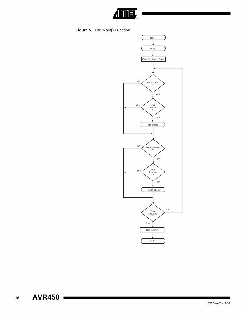
Figure 5. The Main() Function
Setup
ErrorDetected
?
YES
NO
Red LED On
Status = Fast?
YES
NO
END
Main
Clear Termination Status
ErrorDetected
?
YES
NO
Status = Trickle?
YES
NO
fast_charge
ErrorDetected
?
YES
NO
trickle_charge
18 AVR450 1659B–AVR–11/02
AVR450
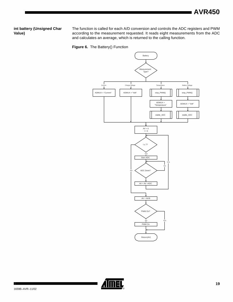
int battery (Unsigned Char Value)
The function is called for each A/D conversion and controls the ADC registers and PWMaccording to the measurement requested. It reads eight measurements from the ADCand calculates an average, which is returned to the calling function.
Figure 6. The Battery() Function
Battery
ADMUX = “Volt”ADMUX =
“Temperature”
ADMUX = “Volt”ADMUX = “Current”
MeasurementType?
Charge Voltage Temperature Battery VoltageCurrent
AV = 0I = 0
Start ADC
I ≤ 7?
ADC Done?
NO
YES
YES
PWM On?
NO
AV = AV/8
AV = AV +ADC
PWM On
NO
Return(AV)
stop_PWM()
stable_ADC
stop_PWM()
stable_ADC
YES
191659B–AVR–11/02

void stable_ADC (Void) The stable_ADC function is used when measuring battery voltage or temperature. Itmakes sure the ADC values are stable inside a defined area. This is important for anaccurate measurement. The function loops until it gets three ADC values where thehighest is no more than one step higher than the lowest.
Figure 7. The stable_ADC() Function
BC.H In this module, the bit handling macros, the charge status and the termination bit maskconstants are defined.
The “charge status” indicates the actual status of the battery charger; fast-charging,trickle charging or if an error has occurred. For Li-Ion and SLA battery types, an indica-tion on the charge mode, constant voltage or constant current is included as well as if Li-Ion is in the final stage of its fast-charge mode (called “delay”). The “termination” indi-cates the reason why fast-charge mode terminated or in case of a charge error wherethe error was detected and can be used for program debugging.
B_DEF.H This module defines the battery to be charged. When a customer designs a batterycharger using the given circuit and program code, this file has to be changed to meet theneeds.
The battery type defines the charging and termination algorithm. If more than one bat-tery type is chosen an error will occur during linking the program, as all functions withthe same functions for different battery types have the same names battery(),fast_charge() and trickle_charge(). An error message will also occur if no battery type ischosen.
The cell number determines the voltage of the battery pack and all related constants. Itis assumed that all cells are in series. Zero cells are not very reasonable but will onlyresult in zero charge current. The voltage range of the buck converter and the voltagemeasurement circuit sets the upper limit.
stable_ADC
V[0] > V[1]+1
V[5] = V[4]V[4] = V[3]V[3] = V[2]
Start ADC
ADC Done?
V[2] = ADC
V[1] = Highest Value ofV[2] to V[5]
V[0] = Lowest Value ofV[2] to V[5]
YES
YES
NO
NO
Return
20 AVR450 1659B–AVR–11/02

AVR450
The capacity (in mA) defines the charge current and all related constants.
All battery types except SLA, are fast charged in a “conservative” way at 1C. SLA ischarged with 2C. This sets the limit for the battery capacity. The buck converter is calcu-lated to supply a maximum current of 1.5 A. The maximum capacity for SLA is 750 mAh,for the other battery types 1500 mAh. If a higher charge current for NiCd or NiMH isrequired, the buck converter layout has to be changed. In case of a current higher than 2A, the current measurement circuit also need some modifications. If batteries with ahigher capacity than calculated above should be charged, it is possible to change thebuck converter or to reduce charge current.
For the Li-Ion battery type, two cell voltages exist, depending on the battery manufac-turer. This voltage, 4.1V or 4.2V, must be edited. It will be included automatically if theLi-Ion definition is chosen. Stating a wrong voltage in this place will not necessarilyresult in an error message, but will lead to incorrect charge methods, which can damagethe battery and the battery charger.
The ADC step parameters are to be edited according to the resistors used in the mea-surement circuitry. This is described under measurement circuits.
The NTC table defines the ADC step value. A step value indicates 0.5�C change in thetemperature. This lookup table is used in NiCd charging. The table may be edited if theNTC is different from the used in this description.
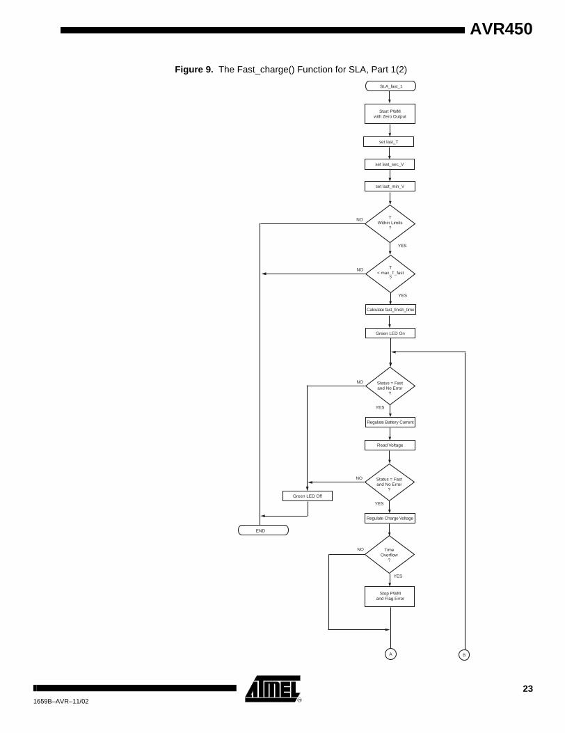
SLA.C
Charge Method Fast-charge of Sealed Lead Acid batteries uses constant voltage. Before chargingbegins, a simple (but surprisingly effective) method is used to determine the charge volt-age. A constant current of 1C (10 mA) is applied and the corresponding battery voltageis measured.
The battery is first charged with Constant voltage, fixing the voltage to that level and letthe current float. When the current drops below 0.2C the charge cycle has finished.Fast-charge mode is then terminated and trickle-charge mode started.
Trickle charge is a constant voltage charging at a level slightly below the fast-chargevoltage. Trickle charge can be terminated after a set time.
Charge Parameter Summary Fast-charge:
Fixed fast-charge voltage = cells * 2450 mV
Trickle charge:
Fixed trickle-charge voltage = cells * 2250 mV
General charge termination:
Absolute minimum temperature T = 0�C
Absolute maximum temperature T = 45�C
Fast-charge termination:
Minimum current threshold I = 0.2C
Fast-charge error:
Maximum fast-charge temperature T = 30�C
Maximum fast-charge time t = 60 min at 1C current
Maximum fast-charge current I = 2C
211659B–AVR–11/02

Trickle charge termination:
None
Figure 8. The Trickle_charge() Function for SLA
SLA_trickle
TWithin Limits
?
YES
NO
Green LED Blinking
Status = Trickleand No Error
?
YES
NO
Regulate Battery Voltage
Start PWMwith Zero Output
END
Green LED Off
Stop PWMand Flag Error
22 AVR450 1659B–AVR–11/02
AVR450
Figure 9. The Fast_charge() Function for SLA, Part 1(2)
SLA_fast_1
TWithin Limits
?
YES
NO
set last_T
Stop PWMand Flag Error
TimeOverflow
?
NO
YES
T< max_T_fast
?
YES
NO
Calculate fast_finish_time
Green LED On
Status = Fastand No Error
?
YES
NO
Regulate Battery Current
A B
Start PWMwith Zero Output
set last_min_V
Green LED Off
END
set last_sec_V
Read Voltage
Regulate Charge Voltage
Status = Fastand No Error
?
YES
NO
231659B–AVR–11/02

Figure 10. The Fast_charge() Function for SLA, Part 2(2)
NiCd.C
Charge Method NiCd battery types are charged with a constant current. In fast-charge mode this currentis set to 1C. In trickle-charge mode, it is C/40. The charging is terminated by the VoltageDrop (-dV/dt) method. Maximum charge voltage, Temperature Rise (dT/dt), and maxi-mum charge time are used as backup terminations.
In case the battery is fully charged, the charge status is automatically changed to trickle-charge, causing the program to jump into the trickle_charge() function.
TemperatureWithin Limits
?
YES
NO
A B
CurrentToo High
?
YES
NO
60 Sec. Over?
YES
NO
CurrentBelow Threshold
?
YES
NO
Stop PWMand Flag Error
Stop PWMand Flag Error
Stop PWMChange Status to Trickle
SLA_fast_2
24 AVR450 1659B–AVR–11/02
AVR450
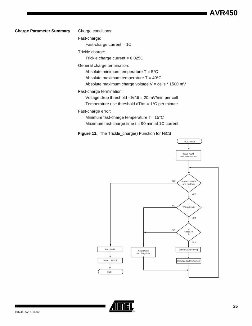
Charge Parameter Summary Charge conditions:
Fast-charge:
Fast-charge current = 1C
Trickle charge:
Trickle charge current = 0.025C
General charge termination:
Absolute minimum temperature T = 5�C
Absolute maximum temperature T = 40�C
Absolute maximum charge voltage V = cells * 1500 mV
Fast-charge termination:
Voltage drop threshold -dV/dt = 20 mV/min per cell
Temperature rise threshold dT/dt = 1�C per minute
Fast-charge error:
Minimum fast-charge temperature T= 15�C
Maximum fast-charge time t = 90 min at 1C current
Figure 11. The Trickle_charge() Function for NiCd
NiCd_trickle
TWithin Limits
?
YES
NO
V< max_V
?
YES
NO
Green LED Blinking
Status = Trickleand No Error
?
YES
NO
Regulate Battery Current
Start PWMwith Zero Output
END
Green LED Off
Stop PWMand Flag Error
Stop PWM
251659B–AVR–11/02

Figure 12. The Fast_charge() Function for NiCd, Part 1(2)
NiCd_fast_1
TWithin Limits
?
YES
NO
Set last_min_T
Stop PWMand Flag Error
TimeOverflow
?
NO
YES
V< max_V
?
YES
NO
T> min_T_fast
?
YES
NO
Calculate fast_finish_time
Green LED On
Status = Fastand No Error
?
YES
NO
Regulate Battery Current
A B
Start PWMwith Zero Output
Set last_min_V
Flag Error
Green LED Off
END
26 AVR450 1659B–AVR–11/02

AVR450
Figure 13. The Fast_charge() Function for NiCd, Part 2(2)
-dVOverflow
?
NO
YES
TemperatureWithin Limits
?
YES
NO
Read last_min_T
Read last_min_V
A B
VoltageOverflow
?
YES
NO
60 Sec. Over?
YES
NO
dT/dtOverflow
?
YES
NO
Stop PWMand Flag Error
Stop PWMand Flag Error
Stop PWMChange Status to Trickle
Stop PWMChange Status to Trickle
NiCd_fast_2
271659B–AVR–11/02

NiMH.C
Charge Method NiMH battery types are charged with a constant current. In fast-charge mode, this cur-rent is set to 1C. In trickle-charge mode it is C/40.
The charging is terminated by the Temperature Rise (dT/dt) and the Voltage Drop (-dV/dt) methods. Maximum charge voltage and maximum charge time are used asbackup terminations.
In case the battery is fully charged the charge status is automatically changed to trickle-charge, causing the program to jump into the trickle_charge() function.
Charge Parameter Summary Charge conditions:
Fast-charge:
Fast-charge current: I = 1C
Trickle charge:
Trickle charge current: I = 0.025C
Maximum trickle-charge time t = 90 min at 0.025C current
General charge termination:
Absolute minimum temperature = 5�C
Absolute maximum temperature = 40�C
Absolute maximum charge voltage = cells * 1500 mV
Fast-charge termination:
Temperature rise threshold dT/dt = 0.5�C per minute
Fast-charge error:
Minimum fast-charge temperature T = 15�C
Maximum fast-charge time t = 90 min at 1C current
28 AVR450 1659B–AVR–11/02

AVR450
Figure 14. The Trickle_charge() Function for NiMH
NiMH_trickle
TWithin Limits
?
YES
NO
V< max_V
?
YES
NO
Green LED Blinking
Status = Trickleand No Error
?
YES
NO
Regulate Battery Current
Start PWMwith Zero Output
END
Green LED Off
TimeOverflow
?
YES
NO
Calculate finish_time
Stop PWMand Flag Error
291659B–AVR–11/02

Figure 15. The Fast_charge() Function for NiMH, Part 1(2)
NiMH_fast_1
TWithin Limits
?
YES
NO
Set last_min_T
Stop PWMand Flag Error
TimeOverflow
?
NO
YES
V< max_V
?
YES
NO
T> min_T_fast
?
YES
NO
Calculate fast_finish_time
Green LED On
Status = Fastand No Error
?
YES
NO
Regulate Battery Current
A B
Start PWMwith Zero Output
Set last_min_V
Green LED Off
END
30 AVR450 1659B–AVR–11/02

AVR450
Figure 16. The Fast_charge() Function for NiMH, Part 2(2)
dT/dtOverflow
?
NO
YES
TemperatureWithin Limits
?
YES
NO
Read last_T
Read last_sec_V
A B
VoltageOverflow
?
YES
NO
60 Sec. Over?
YES
NO
dV/dtOverflow
?
YES
NO
Stop PWMand Flag Error
Stop PWMand Flag Error
Stop PWMChange Status to Trickle
Stop PWMChange Status to Trickle
60 Min. Over?
YES
NO
NiMH_fast_2
311659B–AVR–11/02

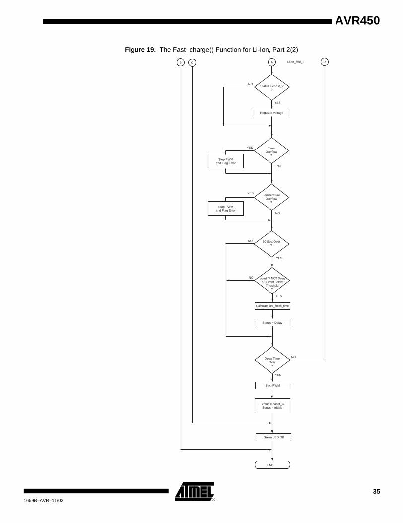
LiIon.C
Charge Method Li-Ion batteries are the most advanced battery types to charge. Fast-charge starts at aconstant current of 1C. This current is kept constant until a cell voltage level of 4.1 or4.2V ± 50 mV is set. Then the battery is charged with constant voltage until the currentdrops below Imin.
For an accurate measurement of the battery voltage (and not the charge voltage), thePWM is turned off during voltage measurements. If the charge method then changesfrom “constant current” to “constant voltage”, the charge voltage is the relevant parame-ter to be measured. This is the reason why there are two voltage measurement modes,one with “PWM turn off” and one without.
Trickle charge of Li-Ion batteries is in principle the same as fast-charge. The current ismuch lower than in fast-charge mode and the constant voltage phase of the trickle-charge mode is simply terminated by a timer.
Charge Parameter Summary Charge conditions:
Fast-charge:
Absolute maximum charge voltage = cells * cell voltage
Voltage tolerance = cells * 50 mV
Fast-charge current = 1C
Minimum current threshold = 50 mA per cell
Trickle charge:
Trickle charge current = 0.025C
Maximum trickle-charge time = 90 min at 0.025C current
General charge termination:
Absolute minimum temperature T = 5�C
Absolute maximum temperature T = 40�C
Fast-charge termination:
See “charge conditions”
Fast-charge error:
Minimum fast-charge temperature 10�C
Maximum fast-charge time = 90 min at 1C current
32 AVR450 1659B–AVR–11/02

AVR450
Figure 17. The Trickle_charge() Function for Li-Ion
LiIon_trickle
TWithin Limits
?
YES
NO
Change Statusfrom const_C
to const_V
Charge VoltageWithinin Limits
?
NO
YES
V< max_V
?
YES
NO
Calculate fast_finish_time
Green LED Blinking
Status = Trickleand No Error
?
YES
NO
Regulate Battery Current
Read Charge Voltage
Start PWMwith Zero Output
END
Green LED Off
Status = Delay
Status = const_V?
YES
NO
Regulate Voltage
TimeOverflow
?
YES
NO
TemperatureOverflow
?
YES
NO
Stop PWMand Flag Error
Stop PWMand Flag Error
Trickle Finish TimeReached
?
NO
YES
Stop PWMand Flag Termination
331659B–AVR–11/02

Figure 18. The Fast_charge() Function for Li-Ion, Part 1(2)
LiIon_fast_1
TWithin Limits
?
YES
NO
Status = const_C
Change Statusfrom const_C
to const_V
Charge VoltageWithinin Limits
?
NO
YES
V< max_V
?
YES
NO
T> min_T_fast
?
YES
NO
Calculate fast_finish_time
Green LED On
Status = Fastand No Error
?
YES
NO
Status = const_C?
YES
NO
Regulate Battery Current
Read Charge Voltage
AB C D
Start PWMwith Zero Output
34 AVR450 1659B–AVR–11/02
AVR450
Figure 19. The Fast_charge() Function for Li-Ion, Part 2(2)
END
Status = const_V?
YES
NO
Green LED Off
Delay TimeOver
?
NO
YES
Regulate Voltage
Stop PWM
TimeOverflow
?
YES
NO
Calculate fast_finish_time
Status = Delay
Status = const_CStatus = trickle
AB C D
TemperatureOverflow
?
YES
NO
60 Sec. Over?
YES
NO
const_V, NOT Delay& Current Below
Threshold?
YES
NO
Stop PWMand Flag Error
Stop PWMand Flag Error
LiIon_fast_2
351659B–AVR–11/02

Suggested Improvements
NiCd batteries suffer from “Memory Effect” – after charging the battery several times, itwill not charge completely. To reset the “memory”, a shunt resistor can be added, allow-ing the MCU to completely discharge the battery prior to charging.
36 AVR450 1659B–AVR–11/02

AVR450
Appendix 1: Schematic
Figure 20. Block Diagram of Main Blocks
VINVCCAREF
AGND
GND
ATtiny15 and 100 kHz buck converter BC2_100k.SCH
VCCVIN
AREFAVCC
AGND
GND
LED0LED1LED2LED3
SWITCH0SWITCH1SWITCH2SWITCH3
AT90S4433 and 14 kHz Buck converterBC2_14K.SCH
GND
AGND
VINVCC
AREFAVCC
SWITCH0SWITCH1SWITCH2SWITCH3
LED0LED1LED2LED3
Powersupply, Switches, LED and Analog referanceBC2_PSU.SCH
371659B–AVR–11/02

Figure 21. Power Supply and Reference Voltage Schematic
LED
0
GR
EE
NLE
D1
RE
DLE
D2
YE
LLO
W
LED
3
GR
EE
N
14
23
S1
14
23
S2
14
23
S3
14
23
S4
R21
330R
R22
330R
R23
330R
C13
100
uF/2
5V
VC
C
C5
100
nF
GN
D
VC
C
14
23
S5
RE
SE
TC
1447
nF
R15
10KV
cc
GN
D
D13
BA
S16
R25
330R
R26
1k R27
1k R28
1k R29
1k
GN
D
GN
D
GN
D
GN
D
Vin
9-1
5V D
C
LED
s an
d sw
itche
sP
ower
supp
ly
1 2 3
J3 DC
_JA
CK
_2_1
MM
Vin
1
GND 2
+5V
3
U6
L78M
05A
BD
TT
P1
VC
C
TP
2
GN
D
TP
14V
IN
I<=
3A
LED
7R
ED
R35
330R
D10
LSM
345
D12
LSM
345
D11
LSM
345
D9
LSM
345
GN
D
VIN
9-12
V A
C
R24
1k
R34
4k7
R14
10k
AG
ND
Vcc
31
2U
5T
L431
AR
EF
C11
100
nF
TP
13
AR
EF
TP
15
AG
ND
AR
EF
Ana
log
volta
ge r
efer
ence
LED
0
LED
1
LED
2
LED
3
SW
ITC
H0
SW
ITC
H1
SW
ITC
H2
SW
ITC
H3
RE
SE
T
LED
5
GR
EE
N
R42
330R
LED
4
GR
EE
N
R41
330R
TP
3
LED
4
TP
4LE
D5
TP
10LE
D0
TP
11LE
D1
TP
19LE
D2
TP
20LE
D3
Tes
tpoi
nt T
P3,
TP
4, T
P10
, TP
11,
TP
19 a
nd T
P20
hav
e no
mar
king
in th
e si
lksc
reen
. The
y ar
e pl
aced
clo
se to
thei
r re
spec
tive
resi
stor
s m
akin
g it
easy
to (
if de
sire
d) c
ut th
e tr
ack
and
patc
h th
e LE
D to
an
oth
er fu
nctio
n.
LED
4
LED
5
38 AVR450 1659B–AVR–11/02

AVR450
Figure 22. ATtiny15 and 100 kHz Buck Converter Schematic
RE
SE
T/P
B5
1A
DC
3/P
B4
2
AD
C2/
PB
33
GN
D4
PB
0/M
OS
I/AR
EF
5
PB
1/M
ISO
/OC
P6
PB
2/A
DC
1/S
CK
7
VC
C8
U3
AT
TIN
Y15
Vcc
GN
D
MO
SI
1V
CC
2
LED
3G
ND
4
RE
SE
T5
GN
D6
SC
K7
GN
D8
MIS
O9
GN
D10
JP1
ISP
GN
D
VC
C
RE
SE
T
GN
D
IBA
T1
VB
AT
1T
BA
T1
PW
M1
R18
0R25
GN
D
1 2
4
3
-T
5
SCL
SDASMBus
B1
BA
TT
ER
Y
R13
10K
R4
680R
GN
D
L2 22uH
GN
DG
ND
+
R19
1k
GN
DBuc
k-co
nver
ter
100k
Hz
R8
33k/
0.1%
R9
33k
R16
10k/
0.1%
R17
10k
AG
ND
AG
ND
Q1
BC
847C
TP
6P
WM
1
TP
12V
BA
T1
TP
9IB
AT
1
R30
10k
GN
D
4
1
5
23
678
Q3
SI4
425D
Y
VIN
AR
EF
TB
AT
1
IBA
T1
VB
AT
1
PW
M1
RE
SE
TA
RE
F
R36
0RA
GN
D
R38
4k7
R37
4k7
Vcc
SD
A
SC
L
R32
330RLE
D6
RE
D
Vcc
NO
TE
: Use
Eith
er R
37 a
nd R
38
or R
8, R
9, R
16 a
nd R
17.
(R37
and
R38
for
SM
Bus
and
R8,
R9,
R
16 a
nd R
17 fo
r vo
ltage
and
cur
rent
m
easu
rem
ent u
sing
the
AT
tiny1
5.)
Usi
ng b
oth
will
not
wor
k in
eith
er c
ase.
AR
EF
C12
100u
F/2
5VC
310
0nF
D4
LSM
345
CD
RH
127-
220
C4
100
nFC
6
100
nF
D2
LSM
345
CC
2520
FC
391659B–AVR–11/02

Figure 23. AT90S4433 and 14 kHz Buck Converter Schematic
RE
SE
T1
PB
0/IC
P14
PD
0/R
XD
2P
D1/
TX
D3
PD
2/IN
T0
4
PD
3/IN
T1
5
PD
7/A
IN1
13
PD
5/T
111
PD
6/A
IN0
12
AR
EF
21
AV
CC
20
PB
5/S
CK
19
PB
2/S
S16
AG
ND
22
AD
C0/
PC
023
AD
C1/
PC
124
AD
C2/
PC
225
AD
C3/
PC
326
AD
C4/
PC
427
AD
C5/
PC
528
PB
4/M
ISO
18P
B3/
MO
SI
17
XT
AL1
9
XT
AL2
10
OC
1/P
B1
15
VC
C7
GN
D8
PD
4/T
06
U4
AT
90S
4433
-PC
MO
SI
1V
CC
2
LED
3G
ND
4
RE
SE
T5
GN
D6
SC
K7
GN
D8
MIS
O9
GN
D10
JP2
ISP
VC
C
VC
CG
ND
GN
D
RE
SE
T
R33
0RG
ND
AG
ND
AV
CC
VC
C
X1
7.37
28M
Hz
GN
DG
ND
AG
ND
X2
7.37
28M
Hz
L4 BLM
-21-
xxx
AR
EF
TxD
RxD
TB
AT
2IB
AT
2V
BA
T2
PW
M2
1 6 2 7 3 8 4 9 5
J1 DB
9G
ND
Ser
ial i
nter
face
(R
S-2
32)
VC
C
GN
D
14 71011 12 9
13 8
RS
232
TT
LV
+2
C1-
3
V-
6
C1+
1
C2+
4
C2-
5
VC
C16
GN
D15
T1
T2
R1
R2
U7
MA
X20
2CS
E
GN
D
GN
D
TxD
RxD
R1
R03
3
GN
D
R2
680R
R5
39k
1 2
4
3
-T
5
SCL
SDASMBus
B2
BA
TT
ER
Y
R6
33k
R10
10k
AG
ND
R11
10 k
R12
10k
R7
33k
R3
680R
GN
D
L1 150u
H
GN
DG
ND
+
R20
1k
GN
D
AG
ND
AV
CC
Q2
BC
847C
Buc
k-co
nver
ter
14kH
z
TP
5P
WM
2
TP
7V
BA
T2
TP
8IB
AT
2
AG
ND
R31
10k
GN
D
3 21
8 4
U1A
LM35
8
5 67
U1B
LM35
8
4
1
5
23
678
Q4
SI4
425D
Y
VIN
AR
EF
TB
AT
2V
BA
T2
IBA
T2
PW
M2
SW
ITC
H0
SW
ITC
H1
SW
ITC
H2
SW
ITC
H3
LED
0LE
D1
LED
2LE
D3
RE
SE
T
R40
4k7
R39
4k7
Vcc
SD
AS
CL
TP
16P
C3
TP
17P
C4
TP
18P
C5
TP
21T
XD
TP
22R
XD
C8
100n
F
C20
100
nF
C23
100
nF C19
100
nF
C17
100
nF
C18
100
nF
C16
22pF
C15
22pF
C9
100n
F
C22
100n
F
C1
1000
uF
/25V
C2
100
nF
D1
LSM
345
D3
LSM
345
C24
100
nF
CC
2520
FC
40 AVR450 1659B–AVR–11/02

AVR450
Appendix 2: Power Supply
The schematic below shows a power supply that supplies both +15V for the batterycharger and +5V for the AVR microcontroller.
The power supply unit for the battery charger is built around a TOP224 from Power Inte-gration. The flyback design technique makes a compact and efficient power supplydesign. The input voltage may vary from 85 VAC to 265 VAC (50 - 60 Hz).
Figure 24. Power Supply Schematic
D30
11,
2A/5
00V
14
23
L301
39 m
HC
302
100n
F/4
00V
5 3
6 7 2 110
T30
1P
hilli
ps E
FD
20 *
*
D30
61N
4148
1 2
4 3
U30
2
PC
817
C30
5
100n
F1
23
Con
trol
U30
1
TO
P22
4
C30
310
0 uF
/400
V
C31
1
100
uF/3
5V
C31
0
100
uF/3
5V
C30
8
1000
uF
/35V
C30
7
1000
uF/3
5V
GN
D
GN
D
GN
D
GN
D
L302
3,3
uH
L303
3,3
uHG
ND
R30
591
kR
304
22k
R30
310
0
R30
610
k
R30
210
0
GN
D
312
U30
3
TL4
31C
304
1n0
C30
910
0 nF
1 2
J1 Mai
ns in
GN
D
VC
C
V15
PD
304
PB
YR
1645
D30
5P
BY
R16
45++
Y1*
* T
wo
serie
s co
nnec
ted,
2.2
nF
, Y2-
capa
cito
rs c
an r
epla
ce C
304
85-2
65V
ACL N
++
D30
3B
YV
26C
D30
2B
ZW
04-1
88
+15
V 1
,5A
+5V
0.5
A
+
C30
110
0 nF
/400
V
** P
ins
4, 8
and
9 o
n T
1 ar
e no
t con
nect
ed
C30
647
uF
+
R30
1
6R2
411659B–AVR–11/02

The transformer T301 is built around an EFD20 transformer kernel from Philips. The pri-mary winding and the bias winding use AWG26 (0.40 mm) wire gauge. The secondarywinding uses AWG20 (0.80 mm). The primary winding and the bias windings are sepa-rated from the two secondary windings with insulation tape. The 5V secondary windingis also a part of the 15V winding. It is very important to make the windings according tothe directions shown in the schematic.
Table 5. Power Supply Part List
Part Part Type Description
R301 6,2� Series resistor for C306 (U301 power supply)
R302 100� Series Resistor for the Opto-coupler
R303 100� Series resistor for the voltage reference
R306 10 k� Feedback circuitry
R304 22 k� Feedback circuitry (5V)
R305 91 k� Feedback circuitry (15V)
C304 1n0/Y1 Y1 capacitor (Can be replaced by 2 * 2.2 nF Y2 capacitors)
C305 100 nF
C309 100 nF
C301 100 nF/400V X Capacitor
C302 100 nF/400V X Capacitor
C310 100 µF/35V Post LC filter
C311 100 µF/35V Post LC filter
C303 100 µF/400V Primary capacitor
C307 1000 µF/35V
C308 1000 µF/35V
L302 3.3 µH Post LC filter
L303 3,3 µH Post LC filter
L301 33 mH Input choke
D301 1.2A/500V Rectifier Bridge
D302 P6KE200 Clamping Zener diode
D303 BYV26C Blocking diode for clamping diode.
D304 PBYR1645 Rectifier diode for 15V supply
D305 PBYR1645 Rectifier diode for 5V supply
D306 1N4148 Rectifier diode for bias/U301 power supply
U301 TOP224 Top switch regulator
U302 TL431 Voltage reference
U303 PC817 Opto-coupler
T301 Phillips EFD20 Transformer, see text below for details
42 AVR450 1659B–AVR–11/02

AVR450
Table 6. Power Supply Transformer Windings
Winding Turns Wire Gauge
Primary winding 86 AWG26
Bias winding 8 AWG26
Secondary winding (5V) 4 AWG20
Secondary winding (15V) 8 (+4) AWG20
431659B–AVR–11/02

Printed on recycled paper.
© Atmel Corporation 2002.Atmel Corporation makes no warranty for the use of its products, other than those expressly contained in the Company’s standard warrantywhich is detailed in Atmel’s Terms and Conditions located on the Company’s web site. The Company assumes no responsibility for any errorswhich may appear in this document, reserves the right to change devices or specifications detailed herein at any time without notice, and doesnot make any commitment to update the information contained herein. No licenses to patents or other intellectual property of Atmel are grantedby the Company in connection with the sale of Atmel products, expressly or by implication. Atmel’s products are not authorized for use as criticalcomponents in life support devices or systems.
Atmel Headquarters Atmel Operations
Corporate Headquarters2325 Orchard ParkwaySan Jose, CA 95131TEL 1(408) 441-0311FAX 1(408) 487-2600
EuropeAtmel SarlRoute des Arsenaux 41Case Postale 80CH-1705 FribourgSwitzerlandTEL (41) 26-426-5555FAX (41) 26-426-5500
AsiaRoom 1219Chinachem Golden Plaza77 Mody Road TsimhatsuiEast KowloonHong KongTEL (852) 2721-9778FAX (852) 2722-1369
Japan9F, Tonetsu Shinkawa Bldg.1-24-8 ShinkawaChuo-ku, Tokyo 104-0033JapanTEL (81) 3-3523-3551FAX (81) 3-3523-7581
Memory2325 Orchard ParkwaySan Jose, CA 95131TEL 1(408) 441-0311FAX 1(408) 436-4314
Microcontrollers2325 Orchard ParkwaySan Jose, CA 95131TEL 1(408) 441-0311FAX 1(408) 436-4314
La ChantrerieBP 7060244306 Nantes Cedex 3, FranceTEL (33) 2-40-18-18-18FAX (33) 2-40-18-19-60
ASIC/ASSP/Smart CardsZone Industrielle13106 Rousset Cedex, FranceTEL (33) 4-42-53-60-00FAX (33) 4-42-53-60-01
1150 East Cheyenne Mtn. Blvd.Colorado Springs, CO 80906TEL 1(719) 576-3300FAX 1(719) 540-1759
Scottish Enterprise Technology ParkMaxwell BuildingEast Kilbride G75 0QR, Scotland TEL (44) 1355-803-000FAX (44) 1355-242-743
RF/AutomotiveTheresienstrasse 2Postfach 353574025 Heilbronn, GermanyTEL (49) 71-31-67-0FAX (49) 71-31-67-2340
1150 East Cheyenne Mtn. Blvd.Colorado Springs, CO 80906TEL 1(719) 576-3300FAX 1(719) 540-1759
Biometrics/Imaging/Hi-Rel MPU/High Speed Converters/RF Datacom
Avenue de RochepleineBP 12338521 Saint-Egreve Cedex, FranceTEL (33) 4-76-58-30-00FAX (33) 4-76-58-34-80
Web Sitehttp://www.atmel.com
1659B–AVR–11/02 0M
ATMEL® and AVR® are the registered trademarks of Atmel.
Other terms and product names may be the trademarks of others.