fatigue tests of hybrid plate girders under combined bending … · 2013-01-18 · fatigue tests of...
TRANSCRIPT

FATIGUE TESTS OF HYBRID PLATE GIRDERS UNDER COMBINED BENDING AND SHEAR
by
David J. Fielding A. A. Toprac
Research Report Number 96-2
Fatigue Strength of Hybrid Plate Girders Under Shear
Research Project Number 3-5-66-96
conducted for
The Texas Highway Department
in cooperation with the U. S. Department of Transportation
Federal Highway Administration Bureau of Public Roads
by the
CENTER FOR HIGHWAY RESEARCH
THE UNIVERSITY OF TEXAS
AUSTIN, TEXAS
July 1967

ACKNOW LEDGMENTS
This investigation is part of the hybrid plate girder research
being conducted at The Structures Fatigue Research Laboratory,
Balcones Research Center, The University of Texas at Austin, Center
for Highway Research under the administration of Dr. John J. McKetta.
This work was sponsored by the Texas Highway Department and the
Bureau of Public Roads. The interest and financial support of the
sponsor and encouragement of the Texas Plate Girder Supervisory
Committee are gratefully acknowledged. The study was supervised by
Dr. A. A. Toprac. Assistance during the testing program was pro
vided by Hai Sang Lew, Dale G. Eyre, and Robert R. Garcia.
The opinions, findings, and conclusions expressed in this
publication are those of the authors and not necessarily those of the
Bureau of Public Roads.
This is the second of three reports that describe the work in
Research Study No. 3-5-66-96, entitled "Fatigue Strength of Hybrid
Plate Girders Under Shear." The first report issued is Report No.
96-1, entitled "Additional Fatigue Tests of Hybrid Plate Girders
Under Pure Bending Moment." The Third report will be prepared
and issued after the completion of tests presently under way.
i
ABSTRACT
Three hybrid plate girders were tested in combined bending
and shear. Both fatigue and static ultimate tests were performed.
The flanges were of A5l4 steel and the webs were of A36 steel. The
stress range in the flanges was 25 ksi with the flange stress fluctua
ting from 25 ksi to 50 ksi. The only variable was the transverse
stiffener length. From the tests it is concluded tha t the U - shaped
cracks that formed under the stiffeners in one girder were not fatal
and that hybrid plate girders under combined bending and shear have
a shorter fatigue life than the same girders under pure bending.
From the static ultimate tests it is concluded that Basler's tension
field theory can be used to predict the ultimate load of hybrid plate
girders under combined bending and shear.
ii

TABLE OF CONTENTS
Page
Acknowledgments i
Abstract ii
L Introduction 1
2. Test Program 2
2.1. Introduction 2
2.2. Test Specimens 2
2.3. Test Setup and Instrumentation 4
2.4. Reference Loads 5
3. Test Procedure and Results 6
3. L Loading History and Procedure 6
3.2. Fatigue Test Results 8
3.3. Static Load Tests 11
4. Discussion 13
4.1. Fatigue Cracks 13
4.2. Stiffener Length 15
4.3. Ultimate Loads 16
5. Conclusions 18
6. Nomenclature 19
7. Tables and Figures 20
8. References 48

1. INTRODUCTION
Because the hybrid plate girder can be of economic value,
research is being conducted at The University of Texas to determine
how these structures behave and to formulate design rules for them.
The test program was begun in 1960 with preliminary static- behavior
tests and continued with preliminary fatigue tests in 1963. The results
of these tests have been published. (1, 2, 3, 4) The tests being pre-
sented here are a part of the overall test program to determine the
fatigue and static behavior of hybrid plate girders.
Fatigue tests and static ultimate tests were run on three
hybrid plate girders with ASTM A514 steel flanges and A36 steel webs.
The loading configuration was such that the interaction of bending and
shear can be studied. The purpose of this report is to pre sent the
test program and the experimental re sults of these tests and to deter-
mine how the results . h h f . t (1, 2, 3, 4) compare Wlt t ose 0 prevlous ests.
The effect of transverse-stiffener length is also investigated.
1

2
2. TEST PROGRAM
2. I Introduction
The primary purpose of these tests was to examine the
effect of shear stress combined with bending stress on the fati
gue behavior of hybrid plate girders and to explore how different
lengths of transverse stiffeners influence fatigue strength. Few
differences among the results of these tests were expected be
cause the girders were identical in all details except transverse
stiffener length. Two of these girders had stiffeners cut 2 in.
short of the tension flange and the third had an 8- inch cutoff.
2. 2 Test Specimens
Figure I shows girder geometry, nominal plate sizes,
stiffener locations, and weld sizes. The two girders, 32550-C2
and 32550-C2R were identical, and girder 32550-CI was different
from these two only in the length of the transverse stiffeners.
Only the end- bearing stiffeners were full-length. The two stiff
eners in the middle three panels intentionally had an 8-inch cutoff
in all girders to prevent fatigue cracks in the web at the toe of
stiffener-to-web weld near the tension flange.
The girder designations are
32550- C2,
32550-C2R, and
32550-CI.

3
The first digit gives the web thickness in sixteenths of an inch. The
next four numbers give the minimum and maximum extreme fiber
stresses of the fatigue test. The IIC" is used to designate the test
series. In the 1101 series, aspect ratios (ratio of panel width to depth)
were 1. 0 for all girders. The next digit, either a 1 or a 2, indicates
the stiffener cutoff length of 8 in. or 2 in., respectively. An R follow
ing the stiffener designation identifies a duplicate girder. The only
variable parameter in these tests was the stiffener length.
The flanges were of ASTM A5l4 steel and the webs were of
A36 steel. The flanges were 8 in. by 1/2 in. plates; the webs were 36
in. deep and 3/16 in. thick. The cros s section is shown in Fig. 2 with
an 8-inch cutoff shown by dashed lines. The panels designated Sl
through S6 in Fig. 3 were the test panels and these had aspect ratios of
1. O. The three central panels had smaller aspect ratios to limit web
deflections. Six-inch end-post panels were used for all girders.
Actual plate dimensions as measured in the laboratory are
given in Table 1. The flange width and thickness were obtained from
measurements made at 31 locations on the flanges of each girder.
The web thickness was obtained from measurements made on a coupon
plate cut from the same plate that was used for the web. The nominal
plate dimensions give a web-slenderness ratio, (ratio of web depth to
thicknes s), of 192. The actual ratios are shown in Table 1. It should
be noted here that the mill scale on the flanges was quite thick (about
0.005 inch) and that no attempt was made to remove it or adjust the
measurements where thickness measurements were made.

4
To determine the static yield point (at zero strain rate) of
the steel, standard tensile tests were made on specimens from the
coupon plates. Two tensile specimens were cut from each coupon
plate; one perpendicular and one parallel to the direction of rolling
of the web plate. Tensile specimens were cut parallel to the direc
tion of rolling of the flange plate. The static yield point, percent
elongation in 8 in., and chemical composition from the mill report
are given in Table 2.
2. 3 Test Setup and Instrumentation
The girders were simply supported at their ends and sub
jected to equal loads applied through hydraulic jacks as shown
schematically in Fig. 3. A pulsator and hydraulic jacks of 120 kips
dynamic capacity and 160 kips static capacity were used to apply
cyclic loads in the fatigue tests and static loads in the ultimate-load
tests. Sufficient lateral bracing was provided to prevent lateral
buckling of the compression flange. The locations of lateral bracing
are indicated in Fig. 3.
Deflections were measured at the supports, load points,
and centerline. Lateral web deflections were measured with a
moveable head dial rig. Panel S3 (See Fig. 3) was instrumented
with electrical-resistance rosette strain gages for the static
ultimate test of 32550-C2R. Gage locations are described in
Chapter 3 where the strains are discussed. In addition, the
girders were whitewashed so that yielding could be observed
During the fatigue tests the slip deflection was measured at the

5
centerline of the girder. Slip deflection is the increase in the de-
flection measured at the maximum fatigue-test load.
2.4 Reference Loads
When the extreme-fiber flange stress is 50 ksi an A36 steel
web should be partially yielded. This means that the linear stress
distribution must be modified to calculate the loads that are required
to give extreme flange-fiber stresses of any magnitude since the
stress distribution is permanently affected after the first load cycle
(See Section 3. 1).
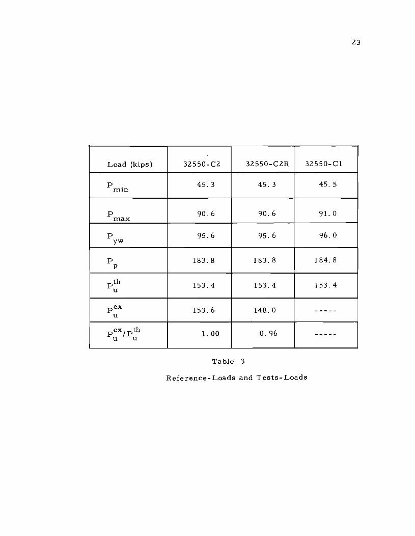
P . and P are given in Table 3 from the stress distri-mln max
butions of Fig. 4d and c, respectively. The load that produces first
yielding in the web, P ,the theoretical ultimate load, P th, and yw u
the load to produce plastic moment, P , are also tabulated. Theop
retical ultimate loads were calculated according to References 5, 6,
and 7, considering the interaction of bending and shear stres sese
Figure 5 shows the interaction diagram between moment and shear
and the ray drawn from the origin of axes represents the loading con-
dition of the test girders. The heavier portion of this ray indicates the
fatigue-test range.

6
3. TEST PROCEDURE AND RESULTS
3. 1 Loading History and Procedure
Figures 6 and 7 are load-versus-centerline-deflection
curves for Girder 3Z550-CZ. These provide a convenient refer-
ence for discus sion of the procedure. Figure 6 is the load-versus-
centerline-deflection curve for the preliminary load cycle prior
to the fatigue test. The specimen was loaded first under static
load to P (Load No.8) in predetermined intervals at which max
time strain readings, girder deflections, and lateral web deflections
were measured. Load numbers were assigned whenever loading
was stopped to record strains and deflections. Then the girder was
unloaded to P . (Load No. 11) and the same data was taken. min
The purpose of this preliminary cycle was to obtain the de-
fleeted web patterns at P . and P . Data at P . was taken after min max min
P was attained because the stress distribution changes when the nlax
web yields. This is shown in Fig. 4 where successive stress dis-
tributions are shown from the original zero load (Load No.1) in
Fig. 4a to the final zero load (load No. 14) in Fig. 4e. If welding
residual stresses are not considered, the stresses originally in
the cross section are as in Fig. 4a which corresponds to Load No. 1
in Fig. 6. The stress distribution is linear (Fig. 4b) until the web
begins to yield. Loading continues to P (Load No.8) where the nlax
stress distribution is as shown in Fig. 4c. Load No. 1 1, P . , min
gives the stress distribution of Fig. 4d which is not the same as
that of Load No.4, P . • When the load is reduced further to mIn
zero, the stress distribution is as shown in Fig. 4e rather than
4a because of the inelastic distortions that have occurred due to
yielding in the web.
After the preliminary loading cycle, fatigue testing was
7
begun. The three specimens were tested at the rate of 260 cycles
per minute. Inspections were made every three hours (or more
frequently) to determine the time and location of the first and all
succeeding cracks and to measure crack propagation. The cracks
were numbered consecutively in the order of discovery.
If a crack formed on the tension side (below the neutral
axis) of the girder it was permitted to propagate until it entered
the tension flange. When a crack entered the tension flange it
was repaired by the "arc-air" method and testing was resumed.
However, once a crack was repaired it usually re- opened after
testing was resumed, thus pointing out the fatal nature of a crack in
the tension area of a plate girder.
After the fatigue test was halted, all cracks were repaired
in order that the girder could be tested to its static ultimate load.
Figure 7 is the load-versus -centerline-deflection curve for the
static ultimate test on Girder 32550-C2. At Load No. 15 in Fig. 7,
zero readings were taken on strain gages and deflection gages.
Then the load was increased in predetermined intervals until in-
elastic behavior was noted; then smaller increments were applied.

8
After failure, the load was returned to zero. Figure 8 is the load-
versus-centerline-deflection curve for the ultimate load test on
32550-C2R.
3.2 Fatigue Test Results
Introduction
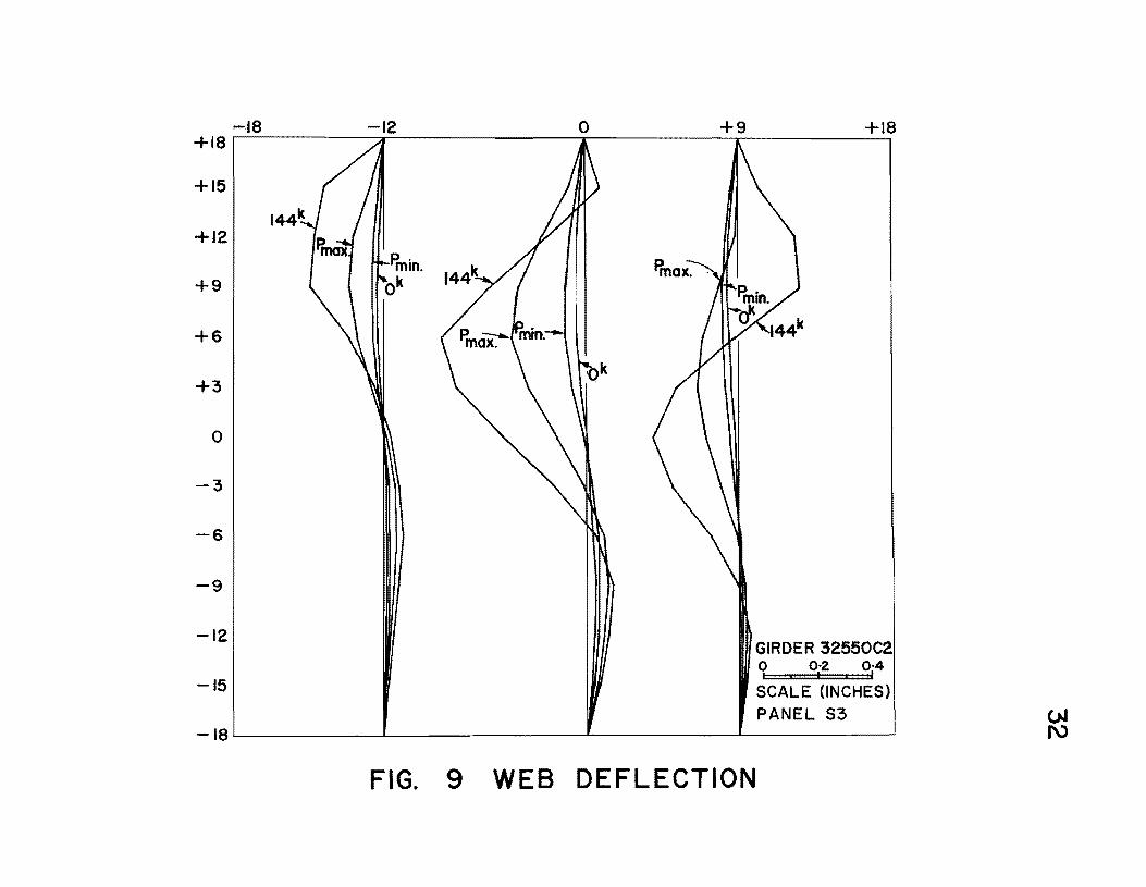
Web Deflections, measured at P and P ., for panel max mln
S3 or S4 of each specimen are shown in Figs. 9 through 11. These
are presented here only to show the magnitude of the deflection of
the web plates in critical test panels (high moment and shear).
Girder 32550-C2
In the preliminary static test (Fig. 6) yielding was first
observed in the web directly under the loading jacks at 64 kips.
At Load No. 7 (80 kips) random localized yielding of the web was
noted in panels Bland B3. Since the actual yield point of the web
steel was 51. 22 ksi none of the web should have yielded; however, the
presence of welding-residual stresses made yielding of some por-
tions entirely possible at low loads.
A fatigue test was run with the load fluctuating between
45. 3 kips and 90.6 kips to produce minimum and maximum extreme
fiber stresses of 25 and 50 ksi, respectively. The first crack was
noted at 316,000 cycles in the web at the web-to-compression flange
fillet weld. At 387,000 cycles, a second crack formed at the
transverse stiffener-to-web fillet weld. These locations are shown

in Fig. 12. At 567, 000 cycles Crack No. 2 entered the tension
flange.
Crack No. 2 was repaired and testing was resumed until
601, 000 cycles at which time Crack No. 2 reopened and a third
crack was noticed. Crack No. 3 was similar to Crack No. 1.
9
The propagation curves of Cracks No. 1 and 2 are plotted in Figs.
13 and 14.
Girder 32550-C2R
The preliminary static test showed that this girder behaved
the same as did 32550-C2 (Fig. 8). In the fatigue test three cracks
(Cracks 1, 2, 5) were found in the web at the toe of the transverse
stiffener-to-we b fillet weld as shown in Fig. 15. Cracks 3 and 4
occurred at flange-web weld discontinuities. The first crack was
noted at 603, 000 cycles. After repeated repairing of the cracks at
the bases of the stiffeners, Crack No. 6 was observed at the toe
of the compression flange-to-web weld. Cracks 3 and 4 in Fig. 15
were the result of defective welding because they formed in the weld
rather than in the web plate.
Girder 32550-Cl
The behavior in the preliminary static test was like that of
32550-C2 except that the initial web deflections (Fig. 11) were
much greater in the bottom (or tension) half of the girder. This
girder had II short" stiffeners and the first fatigue crack was noted

at 60, 000 cycles at the bottom of a stiffener as shown in Fig. 16.
This was a U-shaped crack in the web at the base of the weld.
Cracks No. 3 and 4 were also of this type. The latter crack is
shown in Fig. 17. Once formed, this type of crack propagated
10
so slowly that the growth of crack is believed to have stopped. The
vertical stiffeners of 32550-Cl could be seen moving laterally at
their cutoff ends as a result of lateral web movement. The cracks
at the bottoms of stiffeners appeared first on the tension face of the
breathing web plate. The tension face can be determined from Fig.
11.
Crack No. 2 was a transverse stiffener-to-web weld crack
forming first at the cutoff end of the stiffener as in the case of
the two previous girders. However, in this girder, failure was not
caused by this crack gradually penetrating the tension flange. In
fact, Crack No.2 progressed upward as fast and as much as it
progressed downward. The progress of this crack in panel S4 can
be seen in Fig. 18. Also in this panel, at 412, 000 cycles, Crack No.
5 was noticed in the web at the web-to-compression-flange weld.
This crack grew as shown in Fig. 18 and became so long that the
top of the we b was buckled out of its plane and was completely
separated from the flange. Nevertheless, testing was continued to
see whether or not Crack No. 2 would eventually enter the tension
flange. However, at 634, 000 cycles another crack (Crack No.8)
formed in panel S4 near the neutral axis, and it too grew both upward
and downward until it met Crack No.2. When the two cracks met,
the panel had virtually no stiffness and the centerline slip-deflection
increased rapidly. Figure 19 shows the failed panel. The horizonal

11
arrow shows where the two cracks met and the vertical arrows mark
the extremities of Crack No.5. Figure 20 shows the gradual loss
of stiffness in a cycles-versus-slip diagram. The first two girders
with only 2-inch cutoff did not exhibit this gradual loss of stiffness
(i. e., the slip-deflection was zero). The crack propagation curves
for Cracks No.2 and 5 are given in Figs. 21 and 22.
At the same time that Cracks No.2, 5, and 8 were propagating
in panel 54, similar behavior was noted in panel 53 (Fig. 16), Crack
No.3 was one of the U-shaped cracks that did not grow visibly and
in no way resembled Crack No.2.
3. 3 5ta tic Load- Tests
Girder 32550-C2
Yielding along the tension diagonals was visible at Load No.
25 (Fig. 7) in panels 53 and 54. By the time Load No. 28 was
reached tension-diagonal yielding was visible in all six test panels.
It is questionable whether these were diagonals extending from one
corner to the opposite one or whether principal yielding was along
a line at an an angle less than that of the diagonaL The ultimate
load was 153.6 kips. Figure 23 shows the girder after failure.
The total deformation is small because after ultimate load was
attained the load dropped off rapidly. Figure 24 shows the shear
failure in panel 53.
The web deflections for this girder are shown in Fig. 9
at zero load, P . , and P of the fatigue test, and at 144 kips. min max
12
These show the typical web deflection behavior for girders subjected
to high moment and shear. A buckling valley forms extending from
the upper left corner of the panel to just about the lower right corner;
whereas, in high shear the valley extends from corner to corner. (6)
Girder 32550-C2R
Panel S4 was stiffened wi th a diagonal stiffener after the
fatigue test in an attempt to force a failure in panel S3 which was
instrumented with rosette strain gages. At Load No. 24 (Fig. 8)
tension-field yielding along a line at an angle less than that of the
diagonal was noted in all panels (Fig. 25). A shear failure occurred
at 148.0 kips in panel S5 as shown in Fig. 26. The portion of the
load-deflection curve (Fig. 8) beyond Load No. 25 was not obtained
but P ex was the maximum load that was applied to the specimen. u
The principal stresses at the center of panel S3 are shown
in Fig. 27. Beam-theory stresses and the theoretical web buckling
stres s are indicated Also shown in Fig. 27 is the orientation of the
principal stresses as the load increased; beam theory predicts a
constant inclination of 450
•
Strains in the regions of tension-field anchorage were als 0
measured. These were converted to stresses and plotted in Fig. 28.
The ros ette- gage location is shown in a sketch on the figure and its
coordinates marked. The origin is at the geometric center of the panel.
The inclination of the principal tensile stress is also given in Fig. 28.

13
Girder 32550-C 1
Panel S4 was damaged extensively in the fatigue test and a
repair was not possible, so there was no static-ultimate load test
of this specimen.

14
4. DISCUSSION
4. 1 Fatigue Cracks
Three distinct types of cracks were defined in Reference 3.
These are summarized in the Nomenclature section of this study,
together with two additional types of cracks.
Type 1 cracks formed at the toe of the compression flange
to-web weld. These cracks form where the secondary bending
stresses due to lateral web deflection are greatest. Actual magni
tudes of secondary bending strains in the region of these cracks are
difficult to ascertain but can be approximately calculated from web
deflection data as explained in Reference 8.
Type 2 cracks began at the toe of the transverse stiffener
to-web weld at the cutoff end of the stiffener. These cracks lead
eventually to fracture of the tension flange where the cutoff was 2
in. Figures 14 and 21 show the propagation of Type 2 cracks.
These cracks progressed fas ter with time. Figures 13 and 22 show
the propagation of Type 1 cracks which grow gradually to reduce
the stiffness of the girder web and caused failure in 32550-Cl only
by growing so large that the web became ineffective.
Cracks No. 3 and 4 in 32550-C2R were Type 3 cracks.
These occurred at weld discontinuities.
A new type of crack (Type 4) began around the bottom of the
short stiffeners (Girder 32550-C1 only). Type 4 cracks were noted
very early in the fatigue test of 32550-C 1; however, these cracks
grew very slowly and were not the cause of fracture of the girder.

15
These cracks are not dangerous because in 32550-C1 the first crack
at 60, 000 cycles was a Type 4 crack, but the final fracture of the
girder was at 745,000 cycles. The failure was not caused by the Type
4 crack.
Another type of crack (Type 5) was found in the specimen
with short stiffeners. Type 5 cracks began at the middepth of the
girder at the toe of the transverse stiffener-to-web weld. These
cracks (Cracks No.7 and 8 in Fig. 16) are evidently caused by
web flexing. They formed when the web panels had already lost
much of their stiffness due to Types 1 and 2 cracks. However, in
32550-C1 the combination of a Type 5 crack and a Type 2 crack caused
failure.
In Reference 3 an S-N curve for hybrid plate girders in pure
bending was presented. This curve is reproduced here as Fig. 29.
The results of the tests in combined bending and shear are also plotted
in Fig. 29. It is evident that the combined bending and shear-stress
state results in shorter fa tigue life than predicted by the curve of
Reference 3. The life of Specimen 32550-C1 is taken as 204,000
cycles because the first crack (Type 4) is considered to be solely
the result of terminating the stiffeners 8 inches above the tension
flange. Furthermore, Type 4 cracks do not seem to be of any signi
ficance as far as fatigue life is concerned. However, the Type 2
crack that formed at 204,000 cycles may have formed early due to
the lack of web stiffening ability of the stiffeners with an 8-inch cutoff.
Insufficient data is available to draw any conclusions on this point.

16
4.2 Stiffener Length
The reason for cutting off the stiffeners 2 in. above the
tension flange was to avoid the necessity of welding on or near the
flange since welding is known to cause residual tensile stresses detri
mental to fatigue life. The 8-inch cutoff in Specimen 32550-Cl was
tried to move the welding-residual stress at the end of the stiffener
even closer to the neutral axis, thus trying to prevent Type 2
cracks. Girders 32550-C2 and 32550-C2R were identical and ex
perienced only Type 1 and Type 2 cracks in the test panels. Failure
resulted when Type 2 cracks penetrated into the tension flange.
The 8-inch cutoff resulted in large lateral web deflections
in the lower or tension area of the web. These are shown in Fig.
11 as compared with Figs. 9 and 11 for the other two girders.
The first crack appeared in 32550-Cl at 60,000 cycles, aType 4
crack evidently due to this excessive lateral web movement in
the tension portion of the web. The number and locations of cracks
in this specimen (Fig. 16) indicate a lack of stiffness of the web
plate. Perhaps a stiffener cutoff between the 2-inch and the 8-inch
cutoffs tested may result in a sufficiently stiffened web and a
delayed formation of Type 2 cracks.
In Fig. 16, Crack No.2 is a Type 2 crack in the specimen
with short stiffeners, and it formed earlier than the Type 2 cracks
in the two girders with longer stiffeners. However, at present there
is insufficient data to draw any substantial conclusion from this
observation.

4. 3 Ultimate Loads
The reference loads and the experimental ultimate loads
are given in Table 3. P . and P refer to the fatigue tests. mln max
P is the load at which yielding of the web first occurs due to yw
17
longitudinal primary bending strains. P is the load which corresp
ponds to the plas tic moment. P th is the theoretical ultimate load u
given by Reference 7. considering the interaction between moment
and shear. The treatment in Reference 7 is for homogeneous plate
girders rather than for hybrid girders; however, the experimental
ultimate loads agree well with the predictions for the homogeneous
girders. The last line in Table 3 shows the ratios of P ex, the exu
perimental ultimate load, to P tho The indication is that Basler's u
tension-field theory (5,6, 7) works well for hybrid plate girders.
This is not surprising considering that Basler I s theory is a combi-
nation of three basic phenomena: compression-flange stability, web
buckling, and tension-field development in the web; all of which can
be treated separately as was done in References 5, 6, and 7. Figure
5 shows the loading-condition line (ray from origin with arrowhead)
for the ultimate load tests (and the fatigue tests) on the interaction
diagram. The slope of the loading-condition line is computed in the
lower part of Fig. 5. The circled point where the loading-condition
line intersects the interaction diagram gives the predicted ultimate
load.
Tension-field theory basically says that the compressive
diagonal stress increases until the critical buckling stress is

18
reached at which time the web buckles and thereafter the compressive
diagonal stress remains essentially constant. At the same time, the
tension diagonal stress can increase; it is not limited by buckling.
Figure 27 shows this behavior for panel S3 of Specimen 32550-C2R.
These stresses were determined from an elastic analysis of data
from rosette gages at the geometric center of panel S3. The indi
cation here is that tension-field theory can predict the behavior and
ultimate load of hybrid girders. Figure 27 also shows the slope of
the principal tensile stress which is inclined at 450
or slightly steeper
throughout the test. This indicates that the tension field lies along
the diagonal of the panel. In Fig. 28 the angle ¢ started out at the
beam-theory prediction, but as the load was increased the angle
approached 45 0• This also indicates that a tension "diagonal" forms
in spite of the fact that the whitewash cracked along a line that was
not the diagonal (Fig. 25).

19
5. CONCLUSIONS
1. Fatigue cracks forming at the toe of the transverse stiffener
to web weld propagated into the tension flange in the speci
mens with a 2-inch cutoff.
2. Failure of the specimen with an 8-inch stiffener cutoff was·
through los s of web stiffnes s rather than by tension-flange
fracture.
3. The U - shaped cracks found in one test formed early in the
girder life but were not fatal and remained stable through
several hundred thousand cycles.
4. Hybrid plate girders under combined bending and shear
appear to have a shorter fatigue life than the same girders
under pure bending.

6. FATIGUE CRACK NOMENCLATURE
Classification Description
Type 1 - Cracks forming at the toe of the compression
flange-to-web weld.
Type 2 - Cracks forming at the toe of the transverse
stiffener-to-web weld at the cutoff end of the
stiffener.
20
Type 3 -
Type 4 -
Cracks beginning in the web-to-tension-flange
weld resulting from any discontinuity or notch.
U - shaped cracks around the bottom of "short ll
vertical stiffeners (Fig. 17).
Type 5 - Cracks forming at the toe of the transvers e
stiffener-to-web weld at girder middepth.

21
7. TABLES AND FIGURES

22
GIRDER 32550-C2 32550-C2R 32550-Cl
Web Plate 36" x 0.204" 36" x 0.204" 36" x 0.204"
Flange Plates 7.981" x O. 532" 7.985" x 0.532" 7.998" x 0.534"
a 1.0 1.0 1.0
P 176. 5 1 76.5 1 76.5
Table 1 Dimens ions of Plates
Flange Steel Web Steel
Yield Stress (ks i) 106.24 51. 22
0/0 Elongation 14 24 (in 8 in. )
Chemical Composition (0/0 )
c 0.20 0.21
Mn 0.56 O. 50
P 0.010 0.012
S 0.019 0.024
Si 0.30 O. 10
Cr 1. 01 - - --
Mo 0.21 - - --
Cu 0.33 - - --
B 0.002 - - --
Ti O. 068 - - --
Table 2 Properties of Plates
23
Load (kips) 32550- C2 32550-C2R 32550-Cl
P min
45.3 45. 3 45. 5
p 90. 6 90.6 91. 0 max
p 95.6 95.6 96.0 yw
p 183.8 183.8 184.8 P
pth 153.4 153.4 153.4 u
pex 153.6 148.0 -- - --u
pex/pth 1. 00 o. 96 - - ---u u
Table 3
Reference-Loads and Tests-Loads

SPECIMENS 32550-C2 a 32550-C2R PL a" 1/2"( t ) (A514)
\]1 x yp " ===:j ~
II r--31/£ x 1/2 II _3"x 3/16"- 36
Ix3/16" ~~~'~ /i,L
~ ~ 3/16~ t ~
( typ)(A514) ( typ)(A36) WEB (typ) ~Ta?) 11/4~, a" b"
!PL. alxI/2"(t p)(A514) I
I\.~ ~ • N
" 6" 3'- o~' 3'-0" 3'- 0" 1'-6" 1'- a" 1'- 6" 3'-0" 3'- 0" 3'- 0" 6" --23'-a"
SPECIMEN 32550-CI
36"x'3/16" WEB
18" 6" 3'-0" 3!..d' 3'-0" 1'-6" I'-a' 1'- 6" 3'- 0" 3'- 0" 3 !... 0" 6
,,[
23'-a"
FIG. I TEST SPECIMENS

25
~-8"X 1/2" /
'\ /
3S"x 3/IS"
-0
I It)
---- ----(I)
=N+
"- II
8 x 1/2 ..
FIG. 2 TYPICAL CROSS -SECTION

P P ,-. ,-, ... /-."\ ,. .. ", ,"'
".LATERAL SUPPORT POINTS ,
~ - ,
SI S2 S3 81 82 83 S4 S5 S6
() /\ ~~ ~ 91- 0" 4
1- a" 9 1- 0" ~ ~~
221- a"
MOMENT
+ P
-P
SHEAR
FIG.3 TEST SETUP

50 ksi
.. ~_l" 25ksi ~
a b c d e
FIGURE a b c d e LOAD NO. I 4 8 II 14
LOAD 0 Pmin Pmax Pmin 0
FIG. 4 STRESS DISTRIBUTIONS IN HYBRID PLATE GIRDERS

v Vu
1·0 t------------------~J./
0·8
0·6
0·4
0·2 Mf -=00916
My
28
O~---~------~----~~---~~~~~~~ a 0·2 0·4 0·6 0·8 I-a M My
SLOPE V/Vu P/Vu = My P My
= = = M/My P9/My 9 PVu 9Vu
M = P( Arm) (Arm = 9'-0")
My = 1498 k.ft. Vu = 155·8 k.
SLOPE 1498
1-069 = = 9x155'8
FIG. 5 INTERACTION DIAGRAM

P (k) 90
80
70
60
50
40
30
20
10
29
'~~P- MAX.
I~--THEORY
P P
+ I +
ct.. DEFLECTION.(in.) o uo----~------~----~------~----~~~
o 0·2 0·4 0·6 0·8 1·0 FIG. 6 LOAD Vs <l DEFLECTION (PRELIMINARY
LOAD CYCLE FOR 32550 C2)

P (Kips) 160
140
120
100
80
60
20
0·5
/
/ /
/
'28 / /
27 I
2/ I
IJ04--THEORY
1·0 8~ (INCHES)
30
th ex Pu 31 ~'~f--- Pu
\ \ \ \ \
32
P P
!!~
1·5 2·0
FIG. 7 LOAD- DEFLECTION (32550 C2)

P 160
140
120
100
80
60
40
20
(K)
/ /
/ /
/ I
n~--THEORY
~--Pmin
0-5 I-a 8ct (in.)
31
p.th ... / u ex
/ III( Pu
/ 25
1·5 2-0
FIG. 8 LOAD Vs <t. DEFLECTION FOR 32550 C2R
--18 0 +9 +18 +18r-~------~=--------------T----------~--------~~
+15
+12
+9
+6
+3
o
-3
-6
-9
-12
-15
GIRDER 32550C2 o 0·2 0·4 , I, I
SCALE (INCHES) PANEL S3
-18~--------~~------------~----------~----------~
FIG. 9 WEB DEFLECTION

+18
+15
+12
+9
+6
+3
0
-3
-6
-9
-12
-15
-18
-18 -9 0 +18
Pmax.
GIRDER32550 C2R q 0j2 Oj4
SCALE (INCHES) PANEL S4
FIG. 10 WEB DEFLECTION

-18 -9 0 +9 +18 +18,----------,-----------T----------~--------~~
+15
+12
+9
+6
+3
o
-3
-6
-9
-12
-15
Ffu~ Pmin.
I __ Ok
GIRDER 32550 CI o 0·2 0·4 . . ,
SCALE (INCHES _18~ ________ ~ __________ ~ __________ ~ __ P_A_N_E_L_S_4 __ ~
FIG. II WEB DEFLECTION
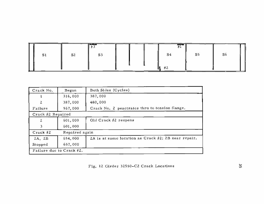
#3 11
S1 S2 S3 S4 S5 S6
t #2
Crack No. Began Both Sides (Cycles)
1 316,000 387,000
2 387,000 480,000
Failure 567,000 Crack No. 2 penetrates thru to tension flange.
Crack #2 Repaired
2 601,000 Old Crack #2 reopens
3 601,000
Crack #2 Repaired again
2A, 2B 654,000 2A is at sam.e location as Crack #2; 2B near repair.
Stopped 657,000
Failure due to Crack #2.
Fig. 12 Girder 32550-C2 Crack Locations

36
FAR SIDE .LENGTH--~""
,......-..... 1---- NEAR SIDE LENGTH
o ~~ __ ~ ________ ~ _______ ~ ____ ~~ ______ ~~~ 400 450 500 550
KILOCYCLES
FIG. 1-3 CRACK PROPAGATION CURVE (CRACK NO.Z)32550-C2
-12 en LIJ J: o Z -::I: b8 z LIJ ..J ~
~ a:: 04
350
NEAR SIDE LENGTH---...........
.--....... ---FAR SIDE LENGTH
450 KILOCYCLES
FIG. 14 CRACK PROPAGATION CURVE (CRACK NO.2) 32550-C2

#6
51 52 53 54 55 56
# .... --. l\ #2 -J 1)1~1 ..... #4 #3
Crack No. Began Both 5ides (Cycles)
1 603,000
2 656,000
3 656,000
R epa.ir of Cracks No. 1,2, 3
2A 700,000
4 &: 5 731,000 753,000
lA 753,000
Repair of Cracks No. lA, 2A, 4,5
4A 793,000
6 793,000 Fig. 15
Testing Halted Girder 32550-C2R
Failure due to Crack No. I (not in test panel). Crack Locations

S1 S2
~#1
Near Side
Crack No. Began
1 60,000
2 204,000
3 314,000
4 314,000
5 412,000
6 412,000
7 597,000
8 633,740
Failure 745,410
- -#6 #5
S3 #71 } #8 S4
#3 .. ." 1 #2
Both Sides
204,000
413,000
413,000
413,000
560,000
462,000
742,000
742,000
Fig. 16 Girder 32550-C 1 Crack Locations
S5
..u #4
S6
w ex>

U_5I>.oped C •• ck ."d •• SUlfu •• cuuo_eu

-
715 742
CRACK NO.5
t__-----¢---(>- NO.2 MEETS NO.8 AT 745,000 CYCLES AND PANEL BUCKLES
1 CRACK NO.2
~l;i ~ ~ ~ -NUMBERS INDICATE KILOCYCLES
\,,-----Q-"'-
\\------4-\.
FIG. 18 CRACK GROWTH
SPECIMEN 32550 CI NEAR SIDE CRACKS 2,5,8
PANEL S4 ~ o

..

en I.LI ..J
800
700
600
500
~400 c.> o ..J ~
300
200
100
42
a ~ ____ ~ ____ ~ ____ ~ ____ ~ ____ ~ ____ ~ __ ___ o 0·01 0·02 0·03 0·04 0·05 0·06
SLIP - DEFLECTION (INCHES)
FIG. 20 SLIP- DEFLECTION CURVE FOR 32550-CI

~2 LLJ :r: o z -
43
FAR SIDE LENGTH -----I ..... """"""
~ .... --NEAR SIDE LENGTH
O~~~ ____________ ~ ______ ~ ____ ~ __________ ~~
16
-fa 12 :r: o z -:r: ~
~8 LLJ ..J
~
~ n:: 0
4
400 500 600 700 KILOCYCLES
FIG. 21 CRACK PROPAGATION CURVE (CRACK NO.2)32550·CI
FAR SIDE LENGTH ----III-f
~--NEAR SIDE LENGTH
o ~~ ______________ ~ ____ ~ __ ----~~----~~~~ 200 300 400 500 600 700
KILOCYCLES FIG. 22 CRACK PROPAGATION CURVE (CRACK NO.5) 32550-CI

44
FIGURE 23
Girder 32550-C2 after Failure
FIGURE 2.4
Shear Failure in Panel $3 (32550-C2.)

45
FIGURE 25
'IDiagonal li Yielding in 32550-C2R
FIGURE 26
Panels S6, S5, S4 (l. tor. ) in 32550-C2R

120
100 I-
80
60
40
20
I I~
I I I I I
25
~--03
(7'1 Y (7'3
~X
46
OJ=-03 (BEAM THEORY) 24
/''--OJ
p P (K)
j 160
120
80
40
t 40 50 60
4> (DEGREES)
11 .... ~f---THEORETICAL WEB BUCKLING STRESS
o o-~----~--~~------~------~------~----~. 5 10 15 20 25
OJ ;-CT3 (KSI)
FIG. 27 PRINCIPAL STRESSES IN PANEL S3 ( 32550 - C2R )
30

47
P (K)
140
~_Oj
120
100
''''--OJ (BEAM THEORY)
80 -"'--05 (BEAM THEORY)
60
P P
160
40
80 20
! 40
l 0 ~ (DEGREES)
40 50 60 70 O~~ __ ~ ______ ~ ______ ~ ____ ~ ______ ~ ______ ~
o 10 20 30 40 50
OJ ,-Oi (KS!)
FIG. 28 PRINCIPAL STRESSES IN PANEL S 3 ( 32550 - C2R )
60

50
40
--W 30 t!) z « 0::
Cf) (J)
W 0:: 20 .-Cf)
10
o
'" "-~
II
IlIO~ 2x10~
FIG. 29
• - A514 FLANGES 8 A36 WEB
K REF. 3 UNDER BENDING AND SHEAR
"-"-~ • " i"-.. .......... .......... ~ ~ r--.-r-
CYCLES
S - N CURVE FOR BENDING TESTS

8. REFERENCES
1. A. A. Toprac "Plate Girders with High Strength Steel Flanges, " Proceedings, 1961 National Engineering Conference, American Institute of Steel Construction.
2. A. A. Toprac IIFatigue Strength of Full Size Hybrid Girders -A Progress Report, II Proceedings, 1963 National Engineering Conference, American Institute of Steel Construction.
3. H. S, Lew and A. A. Toprac IIFatigue Tests of Welded Hybrid Plate Girders Under Constant Moment, II Research Report 77-2F, Center for Highway Research, The University of Texas, Austin, January 1967.
4. Y. Kurobane, D. J. Fielding, and A. A. Toprac IIAdditional Fatigue Tests of Hybrid Plate Girders Under Pure Bending Moment, II Research Report 96-1, Center for Highway Research, The University of Texas, Austin, May, 1967.
5, K. Basler and B. Thurlimann IIStrength of Plate Girders in Bending, II Proc. ASCE, 87, ST 6, August, 1961.
6. K. Basler IIStrength of Plate Girders in Shear, II Froc. ASCE, 87, ST 7, October, 1961.
7. K. Basler IIStrength of Plate Girders Under Combined Bending and Shear, II Proc. ASCE, 87, ST 7, October 1961.
8. B. T. Yen and J. A. Mueller IIFatigue Tests of Large-Size Welded Plate Girders, II Welding Research Council Bulletin No. 118, November, 1966.
49