test rig design for bending fatigue performance...
TRANSCRIPT

Proceedings of the 1st International and 16th National Conference on Machines and Mechanisms (iNaCoMM2013), IIT Roorkee, India, Dec 18-20 2013
Test Rig Design for Bending Fatigue Performance Evaluation of Polymer Based Composite Gears
M Kodeeswaran1, R Suresh2 1Control Actuators Systems Group
2Structural Analysis and Testing Group Vikram Sarabhai Space Centre
Thiruvananthapuram, India [email protected], [email protected]
S Senthilvelan Department of Mechanical Engineering Indian Institute of Technology Guwahati
Guwahati, India [email protected]
Abstract—Test rig for evaluating the bi directional bending fatigue performance of polymer composite gears simulating the actual gear meshing is designed. In the test rig linear motion of servo hydraulic fatigue testing machine is converted into the rotary motion and is used for loading the plastic test gear through steel driver gear. Provision to conduct the tests at different gear roll angle, loading torque and frequency is incorporated in the test rig. The test rig is configured with additional features of monitoring in line torque and angular motion of test gear. Kinematic and kinetic analyses authenticate the utility of the test rig designed.
Keywords—test rig; polymer gear; bending fatigue; servo hydraulic testing machine; kinematic; kinetic
I. INTRODUCTION
Gears find applications in automotive industries, space industries, domestic appliances, printing machineries, computer peripherals, textile machines, windmill, etc,. Generally, metallic gears are used for torque transmissions whereas non-metallic gears for motion transmissions. With an advent of engineering polymers and polymer composites, metallic gears are substituted by polymer based composite gears for medium torque transmissions. Polymer gears have many advantages like reduced weight and dynamic forces, self lubrication, reduced noise and lower manufacturing costs. Performance of gears is assessed by subjecting the gears either to the full scale model tests or to the stand alone tests, when new design/new material is attempted. Stand alone tests are always preferred, considering the time and efforts involved in the full scale model tests. Daniewicz and Moore observed the improved fatigue life of gears by introducing beneficial compressive residual stress [1]. Single tooth bending fixture was used for the studies, where fluctuating bending loads were applied only on highest point single tooth contact of individual gear teeth using servo hydraulic fatigue testing machine. Number of test trials was carried out on the same gear by re-fixing another tooth for the tests. Akata et al., proposed the three point bending test fixture for the stand alone tests using servo hydraulic fatigue testing machine to evaluate the bending fatigue performance [2]. Bending load was applied only on the highest point single tooth contact of individual gear teeth during the tests. Nordin et al., have studied the bending
fatigue strength of case-carburized spur gears with boss using test fixture, where the loads were applied on the individual teeth using eccentric cam mechanism driving pressurizing hydraulic oil which in turn applies the load on gear tooth [3]. From the literature [1-3], it is observed that the gear test rig used for bending fatigue evaluation do not simulate the actual gear meshing condition. Different standalone test rigs simulating actual gear meshing were also developed and the performance tests were conducted using them [4-9]. Kurokawa et al., used power absorption loading by powder dynamometer for performance assessment (service life and wear rate) of PEEK, carbon fiber filled PEEK and carbon fiber reinforced polyamide gears [4,5]. Sentilvelan and Gnanamoorthy developed the power absorption by DC generator test rig for the performance (service life, damping studies, effect of root fillet radius on the performance) evaluation of gears made of nylon6/6, glass fiber filled nylon6/6 and carbon fiber filled nylon6/6 [6,7]. Imrek used the power circulation loading test rig for the performance improvement (service life) of width modified nylon 6 gears [8]. Duzcukoglu also used the power circulation loading test rig for the performance improvement studies of polyamide gears with drilled cooling holes [9]. It was observed that repeated bending fatigue loads only were exerted on the gear teeth during performance evaluation tests [1-9]. However, in real life applications, gears experience cyclic (bi-directional) loading, eg. windmill, robotic manipulator, launch vehicle actuators, etc,. Test rigs exerting bi-directional loading for the performance analysis of plastic gears was not observed in the literatures. In this paper, a new bending fatigue test rig design is presented to evaluate the bending fatigue performance of non-metallic gears, where the cyclic loads will be applied on the gear teeth under actual gear meshing condition
II. CONFIGURATION OF TEST RIG
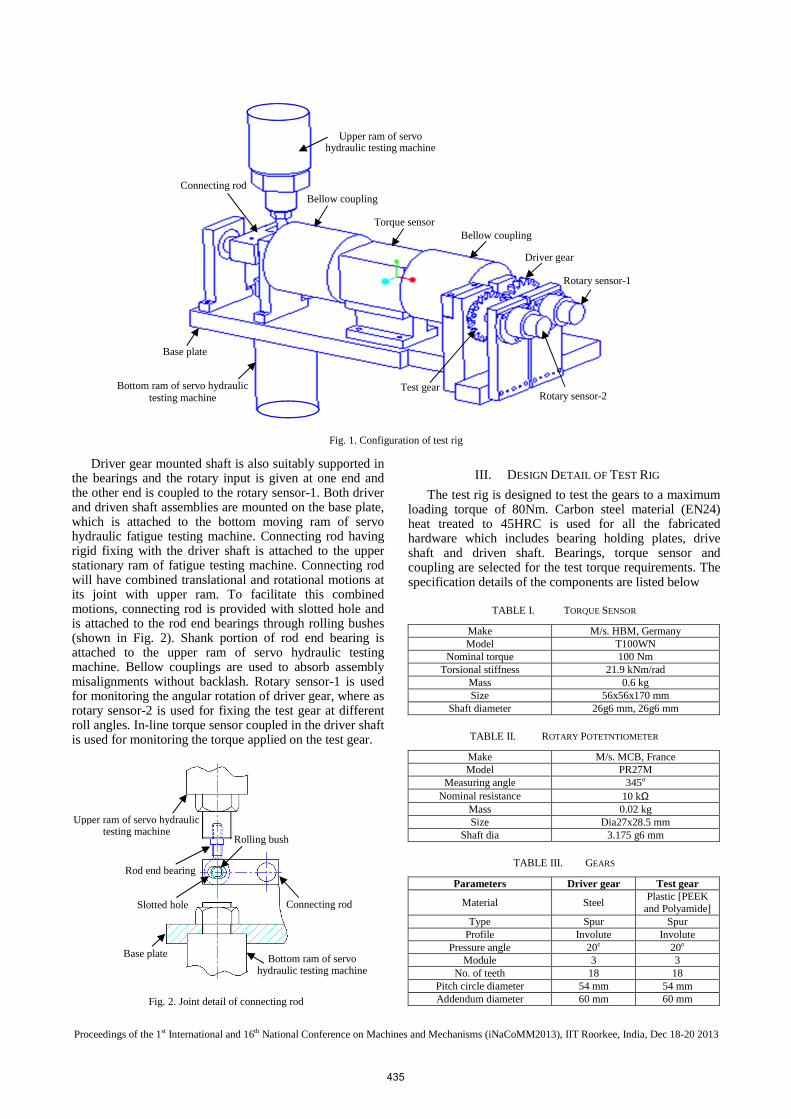
Configuration of test rig is shown in Fig. 1. In the test rig, linear motion of servo hydraulic fatigue testing machine is converted into the rotary motion and is used for loading driven gear (plastic test gear) through steel driver gear. Driven gear mounted shaft is supported in the bearings and is rotationally constrained at one end & the other end is coupled to the rotary sensor-2.
434
Proceedings of the 1st International and 16th National Conference on Machines and Mechanisms (iNaCoMM2013), IIT Roorkee, India, Dec 18-20 2013
Driver gear mounted shaft is also suitably supported in the bearings and the rotary input is given at one end and the other end is coupled to the rotary sensor-1. Both driver and driven shaft assemblies are mounted on the base plate, which is attached to the bottom moving ram of servo hydraulic fatigue testing machine. Connecting rod having rigid fixing with the driver shaft is attached to the upper stationary ram of fatigue testing machine. Connecting rod will have combined translational and rotational motions at its joint with upper ram. To facilitate this combined motions, connecting rod is provided with slotted hole and is attached to the rod end bearings through rolling bushes (shown in Fig. 2). Shank portion of rod end bearing is attached to the upper ram of servo hydraulic testing machine. Bellow couplings are used to absorb assembly misalignments without backlash. Rotary sensor-1 is used for monitoring the angular rotation of driver gear, where as rotary sensor-2 is used for fixing the test gear at different roll angles. In-line torque sensor coupled in the driver shaft is used for monitoring the torque applied on the test gear.
III. DESIGN DETAIL OF TEST RIG
The test rig is designed to test the gears to a maximum loading torque of 80Nm. Carbon steel material (EN24) heat treated to 45HRC is used for all the fabricated hardware which includes bearing holding plates, drive shaft and driven shaft. Bearings, torque sensor and coupling are selected for the test torque requirements. The specification details of the components are listed below
TABLE I. TORQUE SENSOR
Make M/s. HBM, Germany Model T100WN
Nominal torque 100 Nm Torsional stiffness 21.9 kNm/rad
Mass 0.6 kg Size 56x56x170 mm
Shaft diameter 26g6 mm, 26g6 mm
TABLE II. ROTARY POTETNTIOMETER
Make M/s. MCB, France Model PR27M
Measuring angle 345o Nominal resistance 10 kΩ
Mass 0.02 kg Size Dia27x28.5 mm
Shaft dia 3.175 g6 mm
TABLE III. GEARS
Parameters Driver gear Test gear
Material Steel Plastic [PEEK
and Polyamide] Type Spur Spur
Profile Involute Involute Pressure angle 20o 20o
Module 3 3 No. of teeth 18 18
Pitch circle diameter 54 mm 54 mm Addendum diameter 60 mm 60 mm
Fig. 1. Configuration of test rig
Upper ram of servo hydraulic testing machine
Bellow coupling
Torque sensor Bellow coupling
Driver gear
Rotary sensor-1
Rotary sensor-2 Test gear
Connecting rod
Base plate
Bottom ram of servo hydraulic testing machine
Fig. 2. Joint detail of connecting rod
Upper ram of servo hydraulic testing machine
Rod end bearing
Slotted hole
Base plate Bottom ram of servo hydraulic testing machine
Rolling bush
Connecting rod
435

Proceedings of the 1st International and 16th National Conference on Machines and Mechanisms (iNaCoMM2013), IIT Roorkee, India, Dec 18-20 2013
Facewidth 12mm 4mm Hub inner diameter 15mm 15mm Hub outer diameter 25mm 25mm
M/s KBK, Germany make (Model: KB4C/80-78-17-26) bellow couplings (2Nos) were procured, which has a nominal torque transmission of 80Nm. Torsional stiffness of the couplings is 128 kNm/rad with a size of Dia82x78 mm length (Bore sizes: 17H7 mm for drive shaft/drive gear side and 26H7 mm for torque sensor side). Typical mass is 0.76 kg per coupling.
Single row deep groove ball bearings of sizes: (i) 17x35x10 – 3Nos, (ii) 15x24x5 – 2Nos, (iii) 12x21x5 – 4Nos. of M/s. Nachi and M/s. GRW make are used in the test rig. Size and dynamic load carrying capacity of the bearings were the constraints to select the bearings.
IV. TEST CONDITIONS, VARIABLES AND RESULTS
During test, test gear is rotationally constrained and the torque is applied on the test gear by driver steel gear. Different gear roll angles and frequency of load torque at each torque level can be simulated in the test.
TABLE IV. NATURE OF LOAD, TEST VARIABLES AND RESULTS
Nature of load 1. Repeated bending load (half sine/ramp/step) 2. Reversible bending load (sine/ramp/step)
Test variables 1. Load torque: 1 to 20Nm (steps of 5 Nm) 2. Frequency of load: 1 to 5 Hz (steps of 1Hz) 3. Gear roll angle: +/- 16o (steps of 4o)
Test results 1. Torsinal stiffness (Nm/rad) 2. Life assessment under bending fatigue loading (No. of cycles Vs Nm)
V. DESIGN SIMULATION RESULTS
Kinematic and kinetic analyses were carried out for the configuration design of test rig. Though the servo hydraulic fatigue testing machine is planned to be operated in force control mode to exert torque loading on the test gear, linkages will have appreciable kinematic behavior due to low stiffness of plastic gears. Hence, kinematic analysis was initially carried out analytically and verified using ADAMS software for the mechanism. The mechanism layout of test rig is given in Fig. 3.
The base plate with bearing supporting plate, connecting rod, rolling bushes (slider) and the rod end bearing with upper stationary ram are considered as linkages in the mechanism as shown in Fig. 4. One end of the connecting rod, which is attached with base plate, is provided with rotational joint. The other end of connecting rod attaching with slider is simulated with rotational and translational joints. The displacement input (Fig. 5a) is applied at the base plate. It may be noted that the input corresponds to 2Hz sinusoidal (120RPM) with 3mm maximum amplitude. The connecting rod angular displacement and slider translational displacement for one cycle are computed analytically using MATLAB. ADAMS results were compared with analytical results and found to be matching. The analyses results are shown in Fig. 5b & 5c.
Fig. 3. Mechanism layout of test rig
50mm
Driver gear Test gear
Rod end bearing
Base plate
Input
Connecting rod
Fig. 4. Kinematic model (ADAMS)
Connecting rod Slider
Rod end bearing Base plate/ram
b. Angular displacement of connecting rod
c. Slider displacement
Fig. 5. Kinematic analyses results
a. Displacement input of base plate
436

Proceedings of the 1st International and 16th National Conference on Machines and Mechanisms (iNaCoMM2013), IIT Roorkee, India, Dec 18-20 2013
Fig. 6. Kinetic analyses results
It can be seen from Fig. 5b that the initial 90o angular position of connecting rod is changed to 93.43o, hence has an angular displacement of 3.43o. Slider will have 90µ translational displacements, as observed from Fig. 5c, for the base plate sinusoidal displacement of 3mm. The slotted hole in the connecting rod can accommodate the slider movement of 3mm (maximum) against the requirement of 90µ.
Kinetic analysis was carried out analytically for the sinusoidal force input of 100N maximum at 2Hz at base plate (Fig. 6a). The torque exerted on the test gear, gear tooth root bending stress and base plate (ram) displacement were computed. Transmission efficiency of 75% was considered for the analysis. Torque exerted was assessed from the force input and connecting rod length (50mm) and is shown in Fig. 6b. Gear tooth root bending stress was computed using lewis equation with an assumption that only one tooth is experiencing load. Ram displacement was computed from the gear tooth deflection (young’s modulus of plastic material: 2000 MPa).
It was observed that for the maximum force input of 100N, the maximum torque exerted on the gear tooth was 3.75Nm, the maximum gear tooth root bending stress was 37.5MPa (Fig. 6c) and the corresponding maximum ram displacement was 65µ (Fig. 6d). For 80Nm torque loading, the expected ram displacement will be 1.39mm only and the corresponding slider movement will be 41.7µ (max) against the available slider movement of 3mm. Gear tooth bending stress of 800MPa (max) will be developed for 80Nm torque loading, which is much higher than the
generally observed failure stress (~70 to 100MPa) of plastic gears.
Servo hydraulic testing machine is capable of developing the force of 100kN (corresponds to 3750Nm torque at the test rig; Requirement is 80Nm only) at the frequency of 100Hz (corresponds to 6000RPM) and has a stroke of 75mm (against the requirement of 1.39mm bottom ram movement for exerting 80Nm torque loading).
VI. CONCLUSION
Test rig for the bending fatigue performance evaluation of polymer based composite gears was designed, which simulates the actual gear meshing condition during bi-directional loading (maximum of 80Nm). Kinematic and kinetic analyses carried out analytically and using ADAMS software for the mechanism, confirms the adequacy of mechanism to meet the loading requirements. For a displacement input (3mm maximum displacement at 2Hz) at the base plate, the slider movement expected is only 90µ against the available movement of 3mm. Similarly, the slider movement of 41.7µ (max) only is expected for the sinusoidal torque loading input of 80Nm at 2Hz. The bought-out components namely bearings, torque sensor, bellow coupling and rotary sensors are procured. The fabrication drawings generated and the fabrication is in progress.
REFERENCES [1] S.R.Daniewicz, and D.H. Moore, “Increasing the bending fatigue
resistance of spur gear teeth using a presetting process,” International Journal of Fatigue, vol.20, pp. 537–542, 1998.
a. Force input of base plate
b. Torque exerted on the test gear
c. Gear tooth root bending stress
d. Ram displacement
437
Proceedings of the 1st International and 16th National Conference on Machines and Mechanisms (iNaCoMM2013), IIT Roorkee, India, Dec 18-20 2013
[2] E.Akata, M.T.Altınbalık, and Y.Can, “Three point load application in single tooth bending fatigue test for evaluation of gear blank manufacturing methods,” International Journal of Fatigue, vol.26, pp. 785-789, 2004.
[3] I.H.W.Nordin, M.A.Rojan, S.S.C.Abdullah, and M.H.Sulaiman, “Bending fatigue strength of case-carburized spur gears with boss,” International conference on Applications and Design in Mechanical Engineering 2012 (ICADME 2012), Penang, Malaysia, 2012.
[4] M.Kurokawa, Y.Uchiyama, and S.Nagai, “Performance of plastic gear made of carbon fiber reinforced polyether-ether-ketone,” Tribology International, vol.32, pp. 491-497, 1999.
[5] M.Kurokawa, Y.Uchiyama, T.Iwai, and S.Nagai, “Performance of plastic gear made of carbon fiber reinforced polyamide 12,” Wear, vol.254, pp. 468-473, 2003.
[6] S.Senthilvelan, and R.Gnanamoorthy, “Damping characteristics of unreinforced, glass and carbon fiber reinforced nylon 6/6 spur gears,” Polymer Testing, vol.25, pp. 56-62, 2006.
[7] S.Senthilvelan, and R.Gnanamoorthy, “Effect of gear tooth fillet radius on the performance of injection molded Nylon 6/6 gears,” Materials and Design, vol.27, pp. 632-639, 2006.
[8] H.Imrek (2009), “Performance improvement method for Nylon 6 spur gears,” Tribology International, vol.42, pp. 503-510, 2009.
[9] H.Duzcukoglu, “Study on development of polyamide gears for improvement of load-carrying capacity,” Tribology International, vol.42, pp. 1146-1153, 2009.
438