fastrack supreme user guide - sigma electrónica · fastrack supreme is controlled by firmware...
TRANSCRIPT
Plug and Play Wireless CPU®
Fastrack Supreme User Guide
Revision: 003 Date: November 2007
© Restricted Page: 1 / 82
This document is the sole and exclusive property of Wavecom. Not to be distributed or divulged without prior written agreement.
WA_DEV_Fastrk_UGD_001-003 November 5, 2007
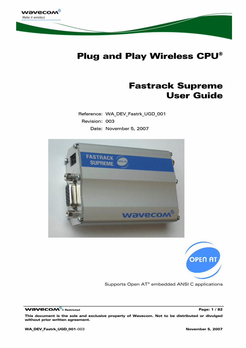
Plug and Play Wireless CPU®
Fastrack Supreme User Guide
Reference: WA_DEV_Fastrk_UGD_001
Revision: 003
Date: November 5, 2007
Supports Open AT® embedded ANSI C applications
Fastrack Supreme User Guide
© Restricted Page: 2 / 82
This document is the sole and exclusive property of Wavecom. Not to be distributed or divulged without prior written agreement.
WA_DEV_Fastrk_UGD_001-003 November 5, 2007
Document History
Revision Date List of revisions
001 June 5, 2007 First Issue
002 September 6, 2007 Update
003 November 5, 2007 Update
Fastrack Supreme User Guide
© Restricted Page: 3 / 82
This document is the sole and exclusive property of Wavecom. Not to be distributed or divulged without prior written agreement.
WA_DEV_Fastrk_UGD_001-003 November 5, 2007
Overview
The Fastrack Supreme 10 and Fastrack Supreme 20 are discrete, rugged cellular Plug & Play Wireless CPU® offering state-of-the-art GSM/GPRS (and EGPRS for Fastrack Supreme 20) connectivity for machine to machine applications.
Proven for reliable, stable performance on wireless networks worldwide, Wavecom’s latest generation of Fastrack Supreme continues to deliver rapid time to market and painless integration.
Having comparable size with the previous M1306B generation, and updated with new features, the Fastrack Supreme offers an Internal Expansion Socket (IES) interface accessible for customer use. Expanding application features is easy without voiding the warrantee of the Fastrack Supreme by simply plugging in of an Internal Expansion Socket Module (IESM) board.
Fully certified, the quad band 850/900/1800/1900 MHz Fastrack Supreme 10 offers GPRS Class 10 capability and Fastrack Supreme 20 offers GPRS/EGPRS Class 10 capability. Both support a powerful open software platform (Open AT®). Open AT® is the world’s most comprehensive cellular development environment, which allows embedded standard ANSI C applications to be natively executed directly on the Wireless CPU®.
Fastrack Supreme is controlled by firmware through a set of AT commands.
This document describes the Fastrack Supreme and gives information on the following topics:
• general presentation,
• functional description,
• basic services available,
• technical characteristics,
• installing and using the Fastrack Supreme,
• user-level troubleshooting.
• recommended accessories to be used with the product.
Note:
This document covers the Fastrack Supreme Plug & Play alone and does not include
The programmable capabilities provided via the use of Open AT® Software Suites.
The development guide for IESM for expanding the application feature through the IES interface.
For detailed, please refer to the documents shown in the "Reference Documents" section.
Fastrack Supreme User Guide
© Restricted Page: 4 / 82
This document is the sole and exclusive property of Wavecom. Not to be distributed or divulged without prior written agreement.
WA_DEV_Fastrk_UGD_001-003 November 5, 2007
RoHS Directive
The Fastrack Supreme is now compliant with RoHS Directive 2002/95/EC, which sets limits for the use of certain restricted hazardous substances. This directive states that "from 1st July 2006, new electrical and electronic equipment put on the market does not contain lead, mercury, cadmium, hexavalent chromium, polybrominated biphenyls (PBB), and polybrominated diphenyl ethers (PBDE)".
Plug & Plays which are compliant with this directive are identified by the RoHS logo on their label.
Disposing of the product
This electronic product is subject to the EU Directive 2002/96/EC for Waste Electrical and Electronic Equipment (WEEE). As such, this product must not be disposed off at a municipal waste collection point. Please refer to local regulations for directions on how to dispose off this product in an environmental friendly manner.
Fastrack Supreme User Guide
© Restricted Page: 5 / 82
This document is the sole and exclusive property of Wavecom. Not to be distributed or divulged without prior written agreement.
WA_DEV_Fastrk_UGD_001-003 November 5, 2007
Cautions
Information furnished herein by WAVECOM is accurate and reliable. However, no responsibility is assumed for its use. Please read carefully the safety recommendations given in Section 9 for an application based on Fastrack Supreme Plug & Play.
Trademarks
®, WAVECOM®, Wireless CPU®, Open AT® and certain other trademarks and logos appearing on this document, are filed or registered trademarks of Wavecom S.A. in France or in other countries. All other company and/or product names mentioned may be filed or registered trademarks of their respective owners.
Copyright
This manual is copyrighted by WAVECOM with all rights reserved. No part of this manual may be reproduced in any form without the prior written permission of WAVECOM. No patent liability is assumed with respect to the use of their respective owners.
Fastrack Supreme User Guide
© Restricted Page: 6 / 82
This document is the sole and exclusive property of Wavecom. Not to be distributed or divulged without prior written agreement.
WA_DEV_Fastrk_UGD_001-003 November 5, 2007
Web Site Support
General information about Wavecom and its range of products:
www.wavecom.com
Specific support is available for the Fastrack Supreme Plug & Play Wireless CPU®:
www.wavecom.com/fastracksupreme
Open AT® Introduction: www.wavecom.com/OpenAT
Developer community for software and hardware:
www.wavecom.com/forum
Fastrack Supreme User Guide
© Restricted Page: 7 / 82
This document is the sole and exclusive property of Wavecom. Not to be distributed or divulged without prior written agreement.
WA_DEV_Fastrk_UGD_001-003 November 5, 2007
Contents
DOCUMENT HISTORY ...............................................................................................2
OVERVIEW ................................................................................................................3
CAUTIONS ................................................................................................................5
TRADEMARKS ..........................................................................................................5
COPYRIGHT ..............................................................................................................5
WEB SITE SUPPORT .................................................................................................6
CONTENTS ...............................................................................................................7
LIST OF FIGURES ....................................................................................................11
LIST OF TABLES......................................................................................................12
1 REFERENCES.....................................................................................................14
1.1 Reference Documents..................................................................................... 14 1.1.1 Open AT® Software Documentation ........................................................ 14 1.1.2 AT Software Documentation................................................................... 14 1.1.3 Delta between M1306B Documents ....................................................... 14 1.1.4 IESM Related Documents ....................................................................... 14
1.2 Abbreviations ................................................................................................. 15
2 PACKAGING ......................................................................................................18
2.1 Contents......................................................................................................... 18 2.2 Packaging Box................................................................................................ 19 2.3 Production Labelling ....................................................................................... 20
3 GENERAL PRESENTATION.................................................................................21
3.1 Description ..................................................................................................... 21 3.2 External Connections...................................................................................... 23
3.2.1 Connectors ............................................................................................. 23 3.2.1.1 Antenna Connector ........................................................................... 23 3.2.1.2 Power Supply Connector................................................................... 23
Fastrack Supreme User Guide
© Restricted Page: 8 / 82
This document is the sole and exclusive property of Wavecom. Not to be distributed or divulged without prior written agreement.
WA_DEV_Fastrk_UGD_001-003 November 5, 2007
3.2.1.3 Sub HD 15-pin Connector ................................................................. 24 3.2.1.4 IES Connector ................................................................................... 26
3.2.2 Power Supply Cable................................................................................ 30
4 FEATURES AND SERVICES ................................................................................31
4.1 Basic Features and Services ........................................................................... 31 4.2 Additional NEW Features................................................................................ 33
4.2.1 Support Additional GSM850/PCS1900 Bands......................................... 33 4.2.2 IES Interface for Easy Expansion of Application Features ........................ 33 4.2.3 Serial Port Auto Shut Down or Improving Power Consumption .............. 33 4.2.4 Real Time Clock (RTC) for Saving Date and Time .................................... 34 4.2.5 SIM Card Lock Feature............................................................................ 34
5 USING THE FASTRACK SUPREME PLUG & PLAY...............................................35
5.1 Getting Started ............................................................................................... 35 5.1.1 Mount the Fastrack Supreme.................................................................. 35 5.1.2 Insert/extract the SIM card to/from the Fastrack Supreme....................... 35 5.1.3 Set up the Fastrack Supreme .................................................................. 37 5.1.4 Check the communication with the Fastrack Supreme............................ 38 5.1.5 Reset the Fastrack Supreme.................................................................... 39
5.2 Specific Recommendations when Using the Fastrack Supreme on Trucks...... 39 5.2.1 Recommended Power Supply Connection on Trucks .............................. 39 5.2.2 Technical Constraints on Trucks ............................................................. 40
5.3 Fastrack Supreme Operational Status ............................................................. 41 5.4 Echo Function Disabled .................................................................................. 42 5.5 Verify the Received Signal Strength ................................................................ 43 5.6 Check the Pin Code Status.............................................................................. 43 5.7 Switch between EU/US Band(s)...................................................................... 44 5.8 Check the Band(s) Selection ........................................................................... 44 5.9 Verify the Fastrack Supreme Network Registration ......................................... 45 5.10 Main AT Commands for the Plug & Play ........................................................ 46 5.11 Firmware Upgrade Procedure ......................................................................... 48
6 TROUBLESHOOTING .........................................................................................49
6.1 No Communication with the Fastrack Supreme through the Serial Link.......... 49 6.2 Receiving "ERROR" Message ........................................................................... 50 6.3 Receiving "NO CARRIER" Message .................................................................. 50
7 FUNCTIONAL DESCRIPTION..............................................................................53
7.1 Architecture.................................................................................................... 53
Fastrack Supreme User Guide
© Restricted Page: 9 / 82
This document is the sole and exclusive property of Wavecom. Not to be distributed or divulged without prior written agreement.
WA_DEV_Fastrk_UGD_001-003 November 5, 2007
7.2 EU and US Bands ........................................................................................... 54 7.2.1 General Presentation............................................................................... 54 7.2.2 AT COMMAND for Bands Switch ........................................................... 54
7.3 Power Supply ................................................................................................. 54 7.3.1 General Presentation............................................................................... 54 7.3.2 Protections.............................................................................................. 54
7.4 RS232 Serial Link............................................................................................ 55 7.4.1 General Presentation............................................................................... 55 7.4.2 Autobauding Mode ................................................................................. 56 7.4.3 Pin Description........................................................................................ 56 7.4.4 Serial Port Auto shut down Feature ........................................................ 56
7.5 General Purpose Input/Output (GPIO) ............................................................. 57 7.6 BOOT ............................................................................................................. 57 7.7 RESET ............................................................................................................ 58
7.7.1 General Presentation............................................................................... 58 7.7.2 Reset Sequence ...................................................................................... 58
7.8 Audio.............................................................................................................. 59 7.8.1 Microphone Inputs.................................................................................. 59 7.8.2 Speaker Outputs ..................................................................................... 60
7.9 Real Time Clock (RTC)..................................................................................... 60 7.10 FLASH LED 61
8 TECHNICAL CHARACTERISTICS ........................................................................62
8.1 Mechanical Characteristics ............................................................................. 62 8.2 Electrical Characteristics ................................................................................. 64
8.2.1 Power Supply ......................................................................................... 64 8.2.2 Power Consumption ............................................................................... 65 8.2.3 Audio Interface ....................................................................................... 68 8.2.4 General Purpose Input/Output................................................................. 69 8.2.5 SIM Interface .......................................................................................... 69 8.2.6 RESET Signal .......................................................................................... 69 8.2.7 RF Characteristics ................................................................................... 70
8.2.7.1 Frequency Ranges ............................................................................ 70 8.2.7.2 RF Performances............................................................................... 71 8.2.7.3 External Antenna .............................................................................. 71
8.3 Environmental Characteristics ........................................................................ 72 8.4 Conformity...................................................................................................... 75 8.5 Protections ..................................................................................................... 75
8.5.1 Power Supply ......................................................................................... 75 8.5.2 Overvoltage............................................................................................. 76 8.5.3 Electrostatic Discharge............................................................................ 76 8.5.4 Miscellaneous......................................................................................... 76
9 SAFETY RECOMMENDATIONS..........................................................................77
Fastrack Supreme User Guide
© Restricted Page: 10 / 82
This document is the sole and exclusive property of Wavecom. Not to be distributed or divulged without prior written agreement.
WA_DEV_Fastrk_UGD_001-003 November 5, 2007
9.1 General Safety ................................................................................................ 77 9.2 Vehicle Safety ................................................................................................. 78 9.3 Care and Maintenance.................................................................................... 78 9.4 Your Responsibility ......................................................................................... 79
10 RECOMMENDED ACCESSORIES........................................................................80
11 ONLINE SUPPORT .............................................................................................82
Fastrack Supreme User Guide
© Restricted Page: 11 / 82
This document is the sole and exclusive property of Wavecom. Not to be distributed or divulged without prior written agreement.
WA_DEV_Fastrk_UGD_001-003 November 5, 2007
List of Figures
Figure 1: Complete package contents ....................................................................... 18 Figure 2: Packaging box ........................................................................................... 19 Figure 3: Production Label ........................................................................................ 20 Figure 4: Fastrack Supreme general description........................................................ 21 Figure 5: Fastrack Supreme holding bridles .............................................................. 22 Figure 6: SMA connector for antenna connection ..................................................... 23 Figure 7: Power supply connector ............................................................................ 24 Figure 8: Sub HD 15-pin connector .......................................................................... 25 Figure 9: IES connector for feature expansion........................................................... 27 Figure 10: Power supply cable.................................................................................. 30 Figure 11: SIM card lock feature ............................................................................... 34 Figure 12: Fastrack Supreme mounting .................................................................... 35 Figure 13: Procedure for SIM card insertion.............................................................. 36 Figure 14: Procedure for SIM card extraction............................................................ 37 Figure 15: Recommended power supply connection on trucks ................................. 40 Figure 16: Example of electrical connection which may dramatically damage the
Fastrack Supreme................................................................................... 41 Figure 17: Functional architecture ............................................................................ 53 Figure 18: RS232 Serial Link signals......................................................................... 55 Figure 19: Reset sequence diagram.......................................................................... 59 Figure 20: Dimensioning diagram............................................................................. 63
Fastrack Supreme User Guide
© Restricted Page: 12 / 82
This document is the sole and exclusive property of Wavecom. Not to be distributed or divulged without prior written agreement.
WA_DEV_Fastrk_UGD_001-003 November 5, 2007
List of Tables
.
Table 1: Power supply connector pin description...................................................... 24 Table 2: Sub HD 15-pin connector description.......................................................... 25 Table 3: IES Connector Description........................................................................... 27 Table 4: Basic features of the Fastrack Supreme....................................................... 31 Table 5: Fastrack Supreme operational status .......................................................... 42 Table 6: Values of received signal strength............................................................... 43 Table 7: AT+CPIN Responses ................................................................................... 43 Table 8: AT+WMBS Band Selection ......................................................................... 44 Table 9: AT+WMBS Responses................................................................................ 44 Table 10: Values of network registration................................................................... 45 Table 11: Main usual AT commands for the Plug & Play .......................................... 46 Table 12: Solutions for no connection with Fastrack Supreme through serial link..... 49 Table 13: Solutions for "NO CARRIER" message ........................................................ 51 Table 14: Interpretation of extended error code ........................................................ 52 Table 15: Mechanical characteristics ........................................................................ 62 Table 16: Electrical characteristics............................................................................ 64 Table 17: Effects of power supply defect .................................................................. 64 Table 18: Power consumption in connected modes (1*) ........................................... 65 Table 19: Power consumption in non-connected modes(1*)..................................... 66 Table 20: Audio parameters caracteristics ................................................................ 68 Table 21: Microphone inputs internal audio filter characteristics .............................. 68 Table 22: Recommended characteristics for the microphone: ................................... 68 Table 23: Recommended characteristics for the speaker: ......................................... 69 Table 24: Operating conditions................................................................................. 69 Table 25: SIM card characteristics............................................................................ 69 Table 26: Electrical characteristics............................................................................ 69 Table 27: Operating conditions................................................................................. 70 Table 28: Frequency ranges...................................................................................... 70 Table 29: Receiver and transmitter RF performances................................................ 71 Table 30: External antenna characteristics................................................................ 71 Table 31: Ranges of temperature.............................................................................. 72
Fastrack Supreme User Guide
© Restricted Page: 13 / 82
This document is the sole and exclusive property of Wavecom. Not to be distributed or divulged without prior written agreement.
WA_DEV_Fastrk_UGD_001-003 November 5, 2007
Table 32: Environmental standard constraints.......................................................... 73 Table 33: List of recommended accessories.............................................................. 80 Table 34: Fastrack Supreme Family .......................................................................... 81
Fastrack Supreme User Guide
References
© Restricted Page: 14 / 82
This document is the sole and exclusive property of Wavecom. Not to be distributed or divulged without prior written agreement.
WA_DEV_Fastrk_UGD_001-003 November 5, 2007
1 References
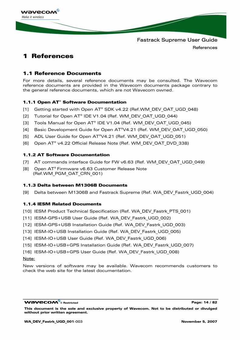
1.1 Reference Documents For more details, several reference documents may be consulted. The Wavecom reference documents are provided in the Wavecom documents package contrary to the general reference documents, which are not Wavecom owned.
1.1.1 Open AT® Software Documentation
[1] Getting started with Open AT® SDK v4.22 (Ref.WM_DEV_OAT_UGD_048)
[2] Tutorial for Open AT® IDE V1.04 (Ref. WM_DEV_OAT_UGD_044)
[3] Tools Manual for Open AT® IDE V1.04 (Ref. WM_DEV_OAT_UGD_045)
[4] Basic Development Guide for Open AT®V4.21 (Ref. WM_DEV_OAT_UGD_050)
[5] ADL User Guide for Open AT®V4.21 (Ref. WM_DEV_OAT_UGD_051)
[6] Open AT® v4.22 Official Release Note (Ref. WM_DEV_OAT_DVD_338)
1.1.2 AT Software Documentation
[7] AT commands interface Guide for FW v6.63 (Ref. WM_DEV_OAT_UGD_049)
[8] Open AT® Firmware v6.63 Customer Release Note (Ref.WM_PGM_OAT_CRN_001)
1.1.3 Delta between M1306B Documents
[9] Delta between M1306B and Fastrack Supreme (Ref. WA_DEV_Fastrk_UGD_004)
1.1.4 IESM Related Documents
[10] IESM Product Technical Specification (Ref. WA_DEV_Fastrk_PTS_001)
[11] IESM-GPS+USB User Guide (Ref. WA_DEV_Fastrk_UGD_002)
[12] IESM-GPS+USB Installation Guide (Ref. WA_DEV_Fastrk_UGD_003)
[13] IESM-IO+USB Installation Guide (Ref. WA_DEV_Fastrk_UGD_005)
[14] IESM-IO+USB User Guide (Ref. WA_DEV_Fastrk_UGD_006)
[15] IESM-IO+USB+GPS Installation Guide (Ref. WA_DEV_Fastrk_UGD_007)
[16] IESM-IO+USB+GPS User Guide (Ref. WA_DEV_Fastrk_UGD_008)
Note:
New versions of software may be available. Wavecom recommends customers to check the web site for the latest documentation.
Fastrack Supreme User Guide
References
© Restricted Page: 15 / 82
This document is the sole and exclusive property of Wavecom. Not to be distributed or divulged without prior written agreement.
WA_DEV_Fastrk_UGD_001-003 November 5, 2007
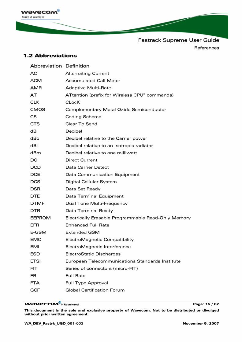
1.2 Abbreviations
Abbreviation Definition
AC Alternating Current
ACM Accumulated Call Meter
AMR Adaptive Multi-Rate
AT ATtention (prefix for Wireless CPU® commands)
CLK CLocK
CMOS Complementary Metal Oxide Semiconductor
CS Coding Scheme
CTS Clear To Send
dB Decibel
dBc Decibel relative to the Carrier power
dBi Decibel relative to an Isotropic radiator
dBm Decibel relative to one milliwatt
DC Direct Current
DCD Data Carrier Detect
DCE Data Communication Equipment
DCS Digital Cellular System
DSR Data Set Ready
DTE Data Terminal Equipment
DTMF Dual Tone Multi-Frequency
DTR Data Terminal Ready
EEPROM Electrically Erasable Programmable Read-Only Memory
EFR Enhanced Full Rate
E-GSM Extended GSM
EMC ElectroMagnetic Compatibility
EMI ElectroMagnetic Interference
ESD ElectroStatic Discharges
ETSI European Telecommunications Standards Institute
FIT Series of connectors (micro-FIT)
FR Full Rate
FTA Full Type Approval
GCF Global Certification Forum
Fastrack Supreme User Guide
References
© Restricted Page: 16 / 82
This document is the sole and exclusive property of Wavecom. Not to be distributed or divulged without prior written agreement.
WA_DEV_Fastrk_UGD_001-003 November 5, 2007
Abbreviation Definition
GND GrouND
GPIO General Purpose Input Output
GPRS General Packet Radio Service
GSM Global System for Mobile communications
HR Half Rate
I Input
IEC International Electrotechnical Commission
IES Internal Expansion Socket
IESM Internal Expansion Socket Module
IMEI International Mobile Equipment Identification
I/O Input / Output
LED Light Emitting Diode
MAX MAXimum
ME Mobile Equipment
MIC MICrophone
Micro-Fit Family of connectors from Molex
MIN MINimum
MNP Microcom Networking Protocol
MO Mobile Originated
MS Mobile Station
MT Mobile Terminated
NOM NOMinal
O Output
Pa Pascal (for speaker sound pressure measurements)
PBCCH Packet Broadcast Control CHannel
PC Personal Computer
PCL Power Control Level
PDP Packet Data Protocol
PIN Personal Identity Number
PLMN Public Land Mobile Network
PUK Personal Unblocking Key
RF Radio Frequency
RFI Radio Frequency Interference
Fastrack Supreme User Guide
References
© Restricted Page: 17 / 82
This document is the sole and exclusive property of Wavecom. Not to be distributed or divulged without prior written agreement.
WA_DEV_Fastrk_UGD_001-003 November 5, 2007
Abbreviation Definition
RI Ring Indicator
RMS Root Mean Square
RTS Request To Send
RX Receive
SIM Subscriber Identification Module
SMA SubMiniature version A RF connector
SMS Short Message Service
SNR Signal-to-Noise Ratio
SPL Sound Pressure Level
SPK SpeaKer
SRAM Static RAM
TCP/IP Transmission Control Protocol / Internet Protocol
TDMA Time Division Multiple Access
TU Typical Urban fading profile
TUHigh Typical Urban, High speed fading profile
TX Transmit
TYP TYPical
VSWR Voltage Stationary Wave Ratio
Fastrack Supreme User Guide
Packaging
© Restricted Page: 18 / 82
This document is the sole and exclusive property of Wavecom. Not to be distributed or divulged without prior written agreement.
WA_DEV_Fastrk_UGD_001-003 November 5, 2007
2 Packaging
2.1 Contents
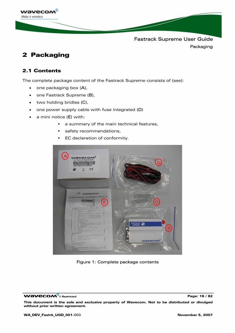
The complete package content of the Fastrack Supreme consists of (see):
• one packaging box (A),
• one Fastrack Supreme (B),
• two holding bridles (C),
• one power supply cable with fuse integrated (D)
• a mini notice (E) with:
a summary of the main technical features,
safety recommendations,
EC declaration of conformity.
Figure 1: Complete package contents
A
D
E C
B
Fastrack Supreme User Guide
Packaging
© Restricted Page: 19 / 82
This document is the sole and exclusive property of Wavecom. Not to be distributed or divulged without prior written agreement.
WA_DEV_Fastrk_UGD_001-003 November 5, 2007
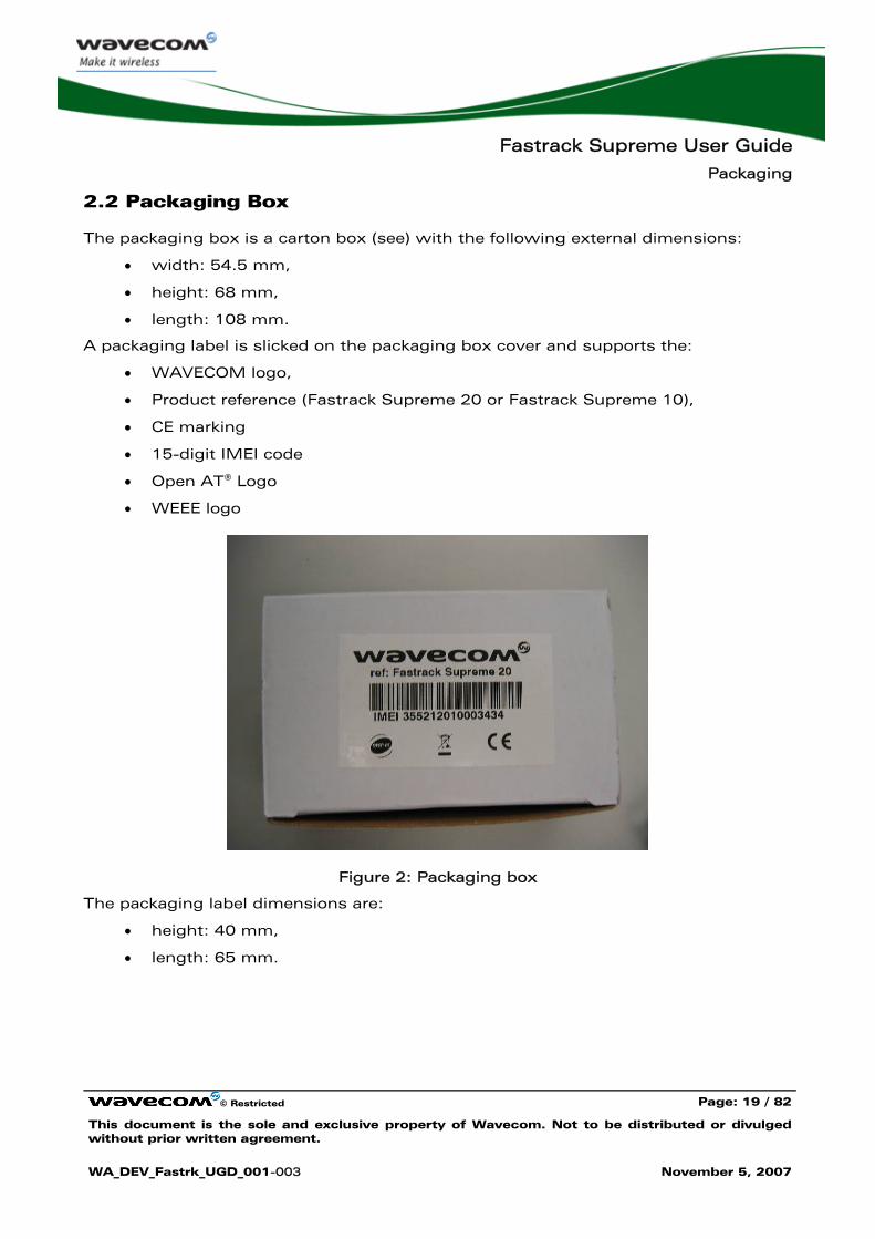
2.2 Packaging Box
The packaging box is a carton box (see) with the following external dimensions:
• width: 54.5 mm,
• height: 68 mm,
• length: 108 mm.
A packaging label is slicked on the packaging box cover and supports the:
• WAVECOM logo,
• Product reference (Fastrack Supreme 20 or Fastrack Supreme 10),
• CE marking
• 15-digit IMEI code
• Open AT® Logo
• WEEE logo
Figure 2: Packaging box
The packaging label dimensions are:
• height: 40 mm,
• length: 65 mm.
Fastrack Supreme User Guide
Packaging
© Restricted Page: 20 / 82
This document is the sole and exclusive property of Wavecom. Not to be distributed or divulged without prior written agreement.
WA_DEV_Fastrk_UGD_001-003 November 5, 2007
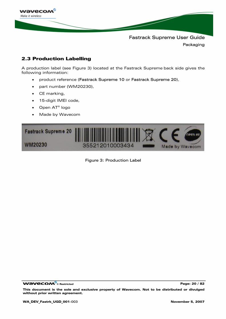
2.3 Production Labelling
A production label (see Figure 3) located at the Fastrack Supreme back side gives the following information:
• product reference (Fastrack Supreme 10 or Fastrack Supreme 20),
• part number (WM20230),
• CE marking,
• 15-digit IMEI code,
• Open AT® logo
• Made by Wavecom
Figure 3: Production Label
Fastrack Supreme User Guide
General Presentation
© Restricted Page: 21 / 82
This document is the sole and exclusive property of Wavecom. Not to be distributed or divulged without prior written agreement.
WA_DEV_Fastrk_UGD_001-003 November 5, 2007
3 General Presentation
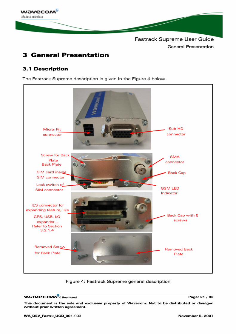
3.1 Description
The Fastrack Supreme description is given in the Figure 4 below.
IES connector for expanding feature, like
GPS, USB, I/O
expander…Refer to Section
3.2.1.4
Removed Screw
for Back Plate
Sub HD
connectorMicro- Fit
connector
Back Plate
Back CapSIM card inside
SIM connector
Lock switch of
SIM connector
SMA
connector
GSM LED Indicator
Screw for Back
Plate
Removed Back Plate
Back Cap with 5 screws
Figure 4: Fastrack Supreme general description
Fastrack Supreme User Guide
General Presentation
© Restricted Page: 22 / 82
This document is the sole and exclusive property of Wavecom. Not to be distributed or divulged without prior written agreement.
WA_DEV_Fastrk_UGD_001-003 November 5, 2007
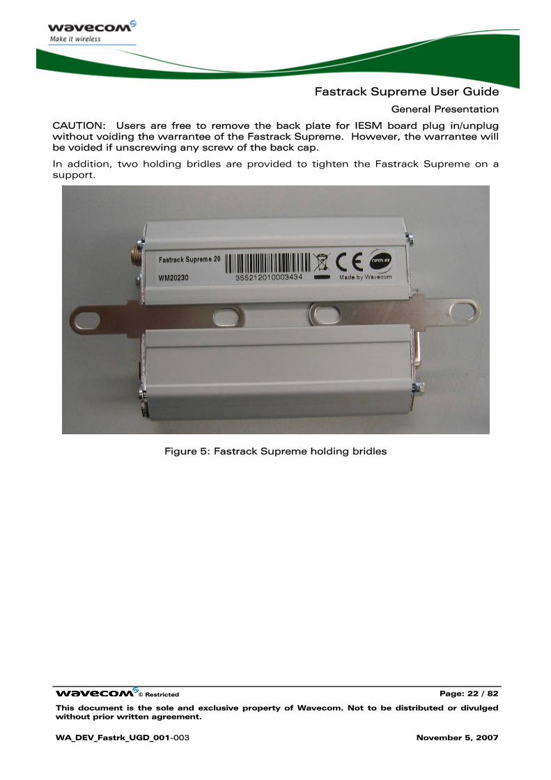
CAUTION: Users are free to remove the back plate for IESM board plug in/unplug without voiding the warrantee of the Fastrack Supreme. However, the warrantee will be voided if unscrewing any screw of the back cap.
In addition, two holding bridles are provided to tighten the Fastrack Supreme on a support.
Figure 5: Fastrack Supreme holding bridles
Fastrack Supreme User Guide
General Presentation
© Restricted Page: 23 / 82
This document is the sole and exclusive property of Wavecom. Not to be distributed or divulged without prior written agreement.
WA_DEV_Fastrk_UGD_001-003 November 5, 2007
3.2 External Connections
3.2.1 Connectors
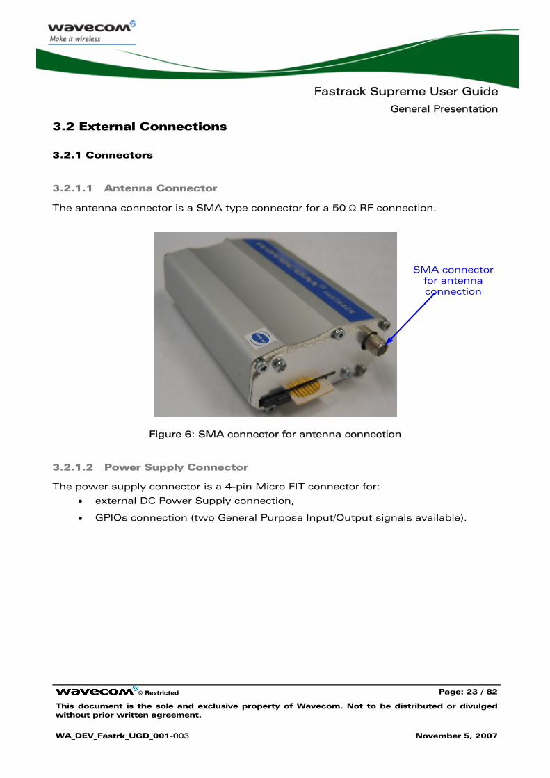
3.2.1.1 Antenna Connector
The antenna connector is a SMA type connector for a 50 Ω RF connection.
Figure 6: SMA connector for antenna connection
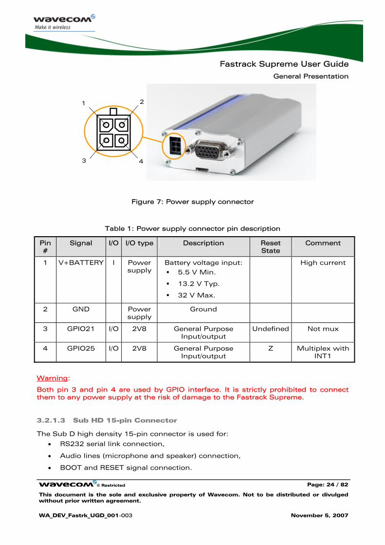
3.2.1.2 Power Supply Connector
The power supply connector is a 4-pin Micro FIT connector for:
• external DC Power Supply connection,
• GPIOs connection (two General Purpose Input/Output signals available).
SMA connector for antenna connection
Fastrack Supreme User Guide
General Presentation
© Restricted Page: 24 / 82
This document is the sole and exclusive property of Wavecom. Not to be distributed or divulged without prior written agreement.
WA_DEV_Fastrk_UGD_001-003 November 5, 2007
1 2
3 4
Figure 7: Power supply connector
Table 1: Power supply connector pin description
Pin #
Signal I/O I/O type Description Reset State
Comment
1 V+BATTERY I Power supply
Battery voltage input:
5.5 V Min.
13.2 V Typ.
32 V Max.
High current
2 GND Power supply
Ground
3 GPIO21 I/O 2V8 General Purpose Input/output
Undefined Not mux
4 GPIO25 I/O 2V8 General Purpose Input/output
Z Multiplex with INT1
Warning:
Both pin 3 and pin 4 are used by GPIO interface. It is strictly prohibited to connect them to any power supply at the risk of damage to the Fastrack Supreme.
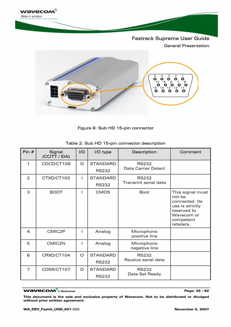
3.2.1.3 Sub HD 15-pin Connector
The Sub D high density 15-pin connector is used for:
• RS232 serial link connection,
• Audio lines (microphone and speaker) connection,
• BOOT and RESET signal connection.
Fastrack Supreme User Guide
General Presentation
© Restricted Page: 25 / 82
This document is the sole and exclusive property of Wavecom. Not to be distributed or divulged without prior written agreement.
WA_DEV_Fastrk_UGD_001-003 November 5, 2007
1 2 3 4 5
6 7 8 9 10
15 14 13 11 12
Figure 8: Sub HD 15-pin connector
Table 2: Sub HD 15-pin connector description
Pin # Signal (CCITT / EIA)
I/O I/O type Description Comment
1 CDCD/CT109 O STANDARD
RS232
RS232 Data Carrier Detect
2 CTXD/CT103 I STANDARD
RS232
RS232 Transmit serial data
3 BOOT I CMOS Boot This signal must not be connected. Its use is strictly reserved to Wavecom or competent retailers.
4 CMIC2P I Analog Microphone positive line
5 CMIC2N I Analog Microphone negative line
6 CRXD/CT104 O STANDARD
RS232
RS232 Receive serial data
7 CDSR/CT107 O STANDARD
RS232
RS232 Data Set Ready
Fastrack Supreme User Guide
General Presentation
© Restricted Page: 26 / 82
This document is the sole and exclusive property of Wavecom. Not to be distributed or divulged without prior written agreement.
WA_DEV_Fastrk_UGD_001-003 November 5, 2007
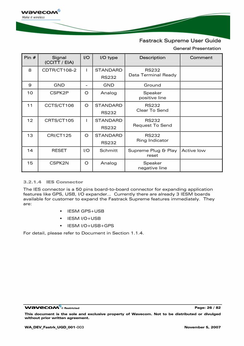
Pin # Signal (CCITT / EIA)
I/O I/O type Description Comment
8 CDTR/CT108-2 I STANDARD
RS232
RS232 Data Terminal Ready
9 GND - GND Ground
10 CSPK2P O Analog Speaker positive line
11 CCTS/CT106 O STANDARD
RS232
RS232 Clear To Send
12 CRTS/CT105 I STANDARD
RS232
RS232 Request To Send
13 CRI/CT125 O STANDARD
RS232
RS232 Ring Indicator
14 RESET I/O Schmitt Supreme Plug & Play reset
Active low
15 CSPK2N O Analog Speaker negative line
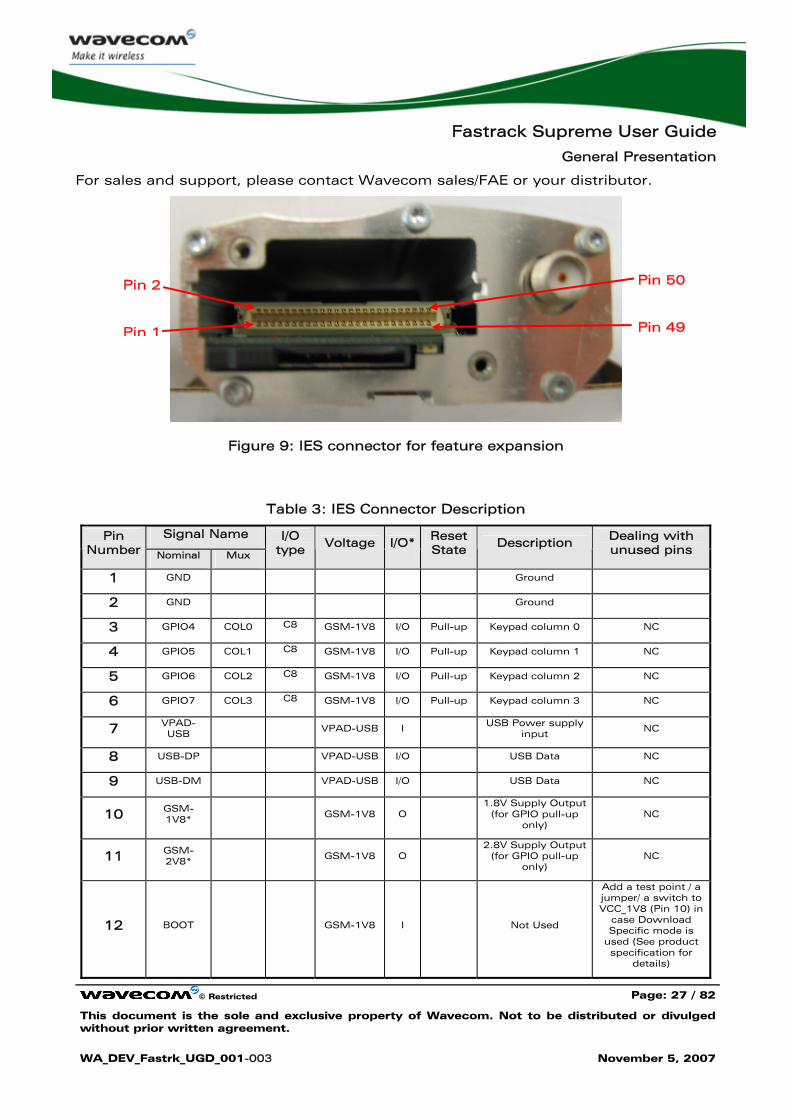
3.2.1.4 IES Connector
The IES connector is a 50 pins board-to-board connector for expanding application features like GPS, USB, I/O expander… Currently there are already 3 IESM boards available for customer to expand the Fastrack Supreme features immediately. They are:
IESM GPS+USB
IESM I/O+USB
IESM I/O+USB+GPS
For detail, please refer to Document in Section 1.1.4.
Fastrack Supreme User Guide
General Presentation
© Restricted Page: 27 / 82
This document is the sole and exclusive property of Wavecom. Not to be distributed or divulged without prior written agreement.
WA_DEV_Fastrk_UGD_001-003 November 5, 2007
For sales and support, please contact Wavecom sales/FAE or your distributor.
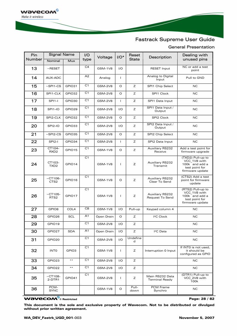
Figure 9: IES connector for feature expansion
Table 3: IES Connector Description
Signal Name Pin Number Nominal Mux
I/O type Voltage I/O* Reset
State Description Dealing with unused pins
1 GND Ground
2 GND Ground
3 GPIO4 COL0 C8 GSM-1V8 I/O Pull-up Keypad column 0 NC
4 GPIO5 COL1 C8 GSM-1V8 I/O Pull-up Keypad column 1 NC
5 GPIO6 COL2 C8 GSM-1V8 I/O Pull-up Keypad column 2 NC
6 GPIO7 COL3 C8 GSM-1V8 I/O Pull-up Keypad column 3 NC
7 VPAD-USB
VPAD-USB I USB Power supply input
NC
8 USB-DP VPAD-USB I/O USB Data NC
9 USB-DM VPAD-USB I/O USB Data NC
10 GSM-1V8*
GSM-1V8 O 1.8V Supply Output
(for GPIO pull-up only)
NC
11 GSM-2V8*
GSM-1V8 O
2.8V Supply Output (for GPIO pull-up
only) NC
12 BOOT
GSM-1V8 I Not Used
Add a test point / a jumper/ a switch to VCC_1V8 (Pin 10) in
case Download Specific mode is
used (See product specification for
details)
Pin 2
Pin 1
Pin 50
Pin 49
Fastrack Supreme User Guide
General Presentation
© Restricted Page: 28 / 82
This document is the sole and exclusive property of Wavecom. Not to be distributed or divulged without prior written agreement.
WA_DEV_Fastrk_UGD_001-003 November 5, 2007
Signal Name Pin Number Nominal Mux
I/O type Voltage I/O* Reset
State Description Dealing with unused pins
13 ~RESET C4 GSM-1V8 I/O RESET Input NC or add a test point
14 AUX-ADC A2 Analog I Analog to Digital Input
Pull to GND
15 ~SPI1-CS GPIO31 C1 GSM-2V8 O Z SPI1 Chip Select NC
16 SPI1-CLK GPIO32 C1 GSM-2V8 O Z SPI1 Clock NC
17 SPI1-I GPIO30 C1 GSM-2V8 I Z SPI1 Data Input NC
18 SPI1-IO GPIO29 C1 GSM-2V8 I/O Z SPI1 Data Input / Output
NC
19 SPI2-CLK GPIO32 C1 GSM-2V8 O Z SPI2 Clock NC
20 SPI2-IO GPIO33 C1 GSM-2V8 I/O Z SPI2 Data Input / Output
NC
21 ~SPI2-CS GPIO35 C1 GSM-2V8 O Z SPI2 Chip Select NC
22 SPI2-I GPIO34 C1 GSM-2V8 I Z SPI2 Data Input NC
23 CT104-RXD2
GPIO15 C1 GSM-1V8 O Z Auxiliary RS232 Receive
Add a test point for firmware upgrade
24 CT103-TXD2 GPIO14
C1
GSM-1V8 I Z Auxiliary RS232
Transmit
(TXD2) Pull-up to VCC_1V8 with
100k� and add a test point for
firmware update
25 ~CT106-CTS2 GPIO16
C1 GSM-1V8 O Z
Auxiliary RS232 Clear To Send
(CTS2) Add a test point for firmware
update
26 ~CT105-RTS2
GPIO17
C1
GSM-1V8 I Z Auxiliary RS232 Request To Send
(RTS2) Pull-up to VCC_1V8 with
100k� and add a test point for
firmware update
27 GPIO8 COL4 C8 GSM-1V8 I/O Pull-up Keypad column 4 NC
28 GPIO26 SCL A1 Open Drain O Z I²C Clock NC
29 GPIO19 C1 GSM-2V8 I/O Z NC
30 GPIO27 SDA A1 Open Drain I/O Z I²C Data NC
31 GPIO20 C1 GSM-2V8 I/O Undefined
NC
32 INT0 GPIO3 C1
GSM-1V8 I Z Interruption 0 Input If INT0 is not used,
it should be configured as GPIO
33 GPIO23 ** C1 GSM-2V8 I/O Z NC
34 GPIO22 ** C1 GSM-2V8 I/O Z NC
35 ~CT108-2-DTR1 GPIO41
C1 GSM-2V8 I Z
Main RS232 Data Terminal Ready
(DTR1) Pull-up to VCC_2V8 with
100k�
36 PCM-SYNC
GSM-1V8 O Pull-down
PCM Frame Synchro
NC
Fastrack Supreme User Guide
General Presentation
© Restricted Page: 29 / 82
This document is the sole and exclusive property of Wavecom. Not to be distributed or divulged without prior written agreement.
WA_DEV_Fastrk_UGD_001-003 November 5, 2007
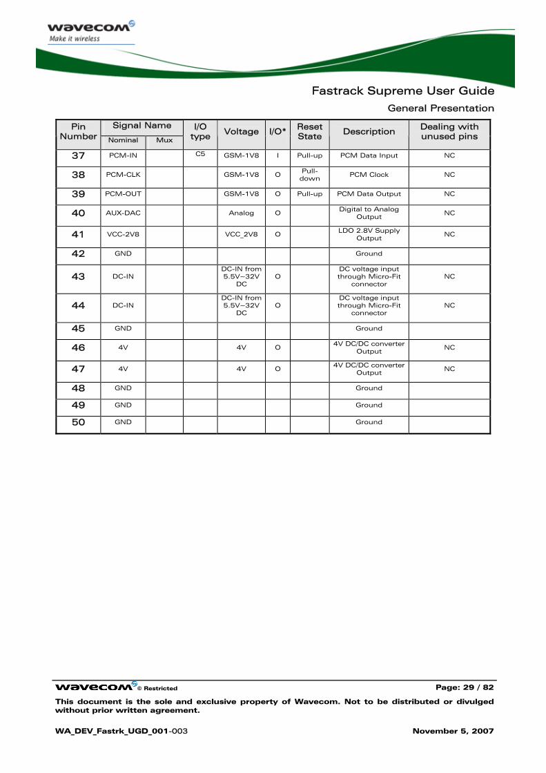
Signal Name Pin Number Nominal Mux
I/O type Voltage I/O* Reset
State Description Dealing with unused pins
37 PCM-IN C5 GSM-1V8 I Pull-up PCM Data Input NC
38 PCM-CLK GSM-1V8 O Pull-down
PCM Clock NC
39 PCM-OUT GSM-1V8 O Pull-up PCM Data Output NC
40 AUX-DAC Analog O Digital to Analog Output
NC
41 VCC-2V8 VCC_2V8 O LDO 2.8V Supply Output
NC
42 GND Ground
43 DC-IN DC-IN from
5.5V~32VDC
O DC voltage input through Micro-Fit
connector NC
44 DC-IN DC-IN from
5.5V~32VDC
O DC voltage input through Micro-Fit
connector NC
45 GND Ground
46 4V 4V O 4V DC/DC converter Output
NC
47 4V 4V O 4V DC/DC converter Output
NC
48 GND Ground
49 GND Ground
50 GND Ground
Fastrack Supreme User Guide
General Presentation
© Restricted Page: 30 / 82
This document is the sole and exclusive property of Wavecom. Not to be distributed or divulged without prior written agreement.
WA_DEV_Fastrk_UGD_001-003 November 5, 2007
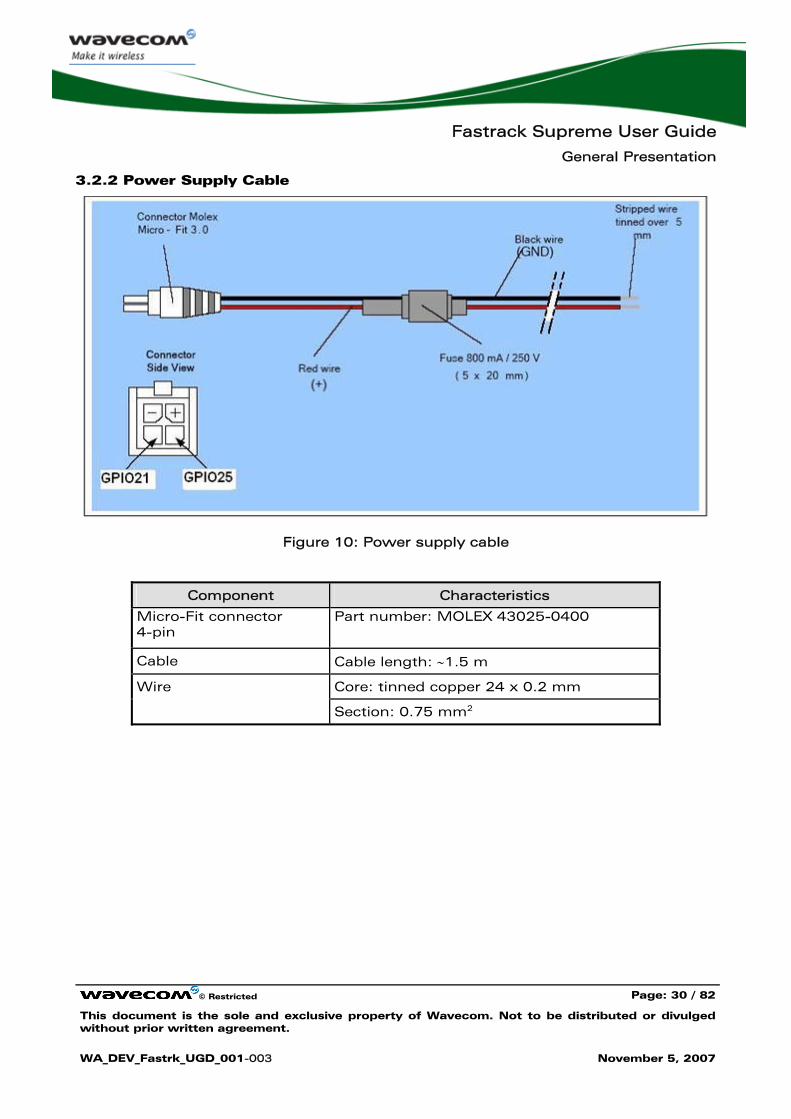
3.2.2 Power Supply Cable
Figure 10: Power supply cable
Component Characteristics
Micro-Fit connector 4-pin
Part number: MOLEX 43025-0400
Cable Cable length: ∼1.5 m
Core: tinned copper 24 x 0.2 mm Wire
Section: 0.75 mm2
Fastrack Supreme User Guide
Features and Services
© Restricted Page: 31 / 82
This document is the sole and exclusive property of Wavecom. Not to be distributed or divulged without prior written agreement.
WA_DEV_Fastrk_UGD_001-003 November 5, 2007
4 Features and Services
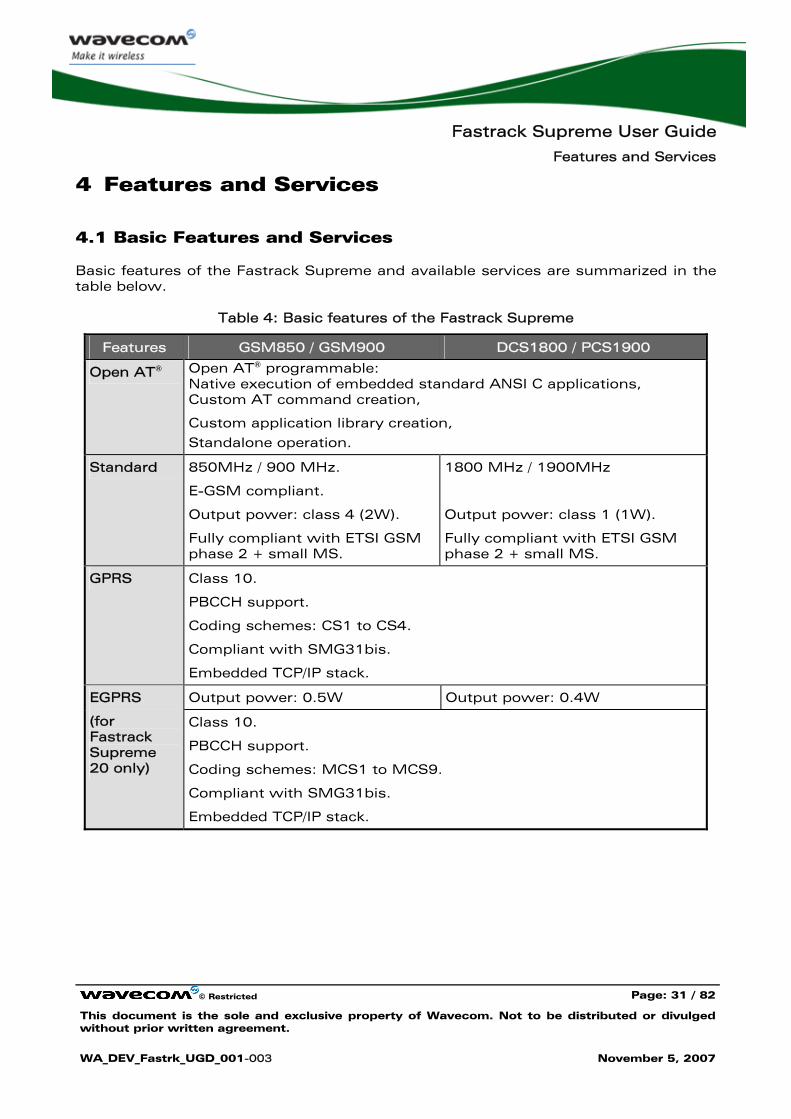
4.1 Basic Features and Services
Basic features of the Fastrack Supreme and available services are summarized in the table below.
Table 4: Basic features of the Fastrack Supreme
Features GSM850 / GSM900 DCS1800 / PCS1900
Open AT® Open AT® programmable: Native execution of embedded standard ANSI C applications, Custom AT command creation,
Custom application library creation,
Standalone operation.
Standard 850MHz / 900 MHz.
E-GSM compliant.
Output power: class 4 (2W).
Fully compliant with ETSI GSM phase 2 + small MS.
1800 MHz / 1900MHz
Output power: class 1 (1W).
Fully compliant with ETSI GSM phase 2 + small MS.
GPRS Class 10.
PBCCH support.
Coding schemes: CS1 to CS4.
Compliant with SMG31bis.
Embedded TCP/IP stack.
Output power: 0.5W Output power: 0.4W EGPRS
(for Fastrack Supreme 20 only)
Class 10.
PBCCH support.
Coding schemes: MCS1 to MCS9.
Compliant with SMG31bis.
Embedded TCP/IP stack.
Fastrack Supreme User Guide
Features and Services
© Restricted Page: 32 / 82
This document is the sole and exclusive property of Wavecom. Not to be distributed or divulged without prior written agreement.
WA_DEV_Fastrk_UGD_001-003 November 5, 2007
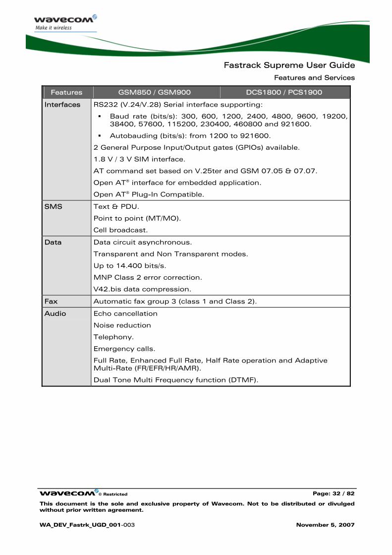
Features GSM850 / GSM900 DCS1800 / PCS1900
Interfaces RS232 (V.24/V.28) Serial interface supporting:
Baud rate (bits/s): 300, 600, 1200, 2400, 4800, 9600, 19200, 38400, 57600, 115200, 230400, 460800 and 921600.
Autobauding (bits/s): from 1200 to 921600.
2 General Purpose Input/Output gates (GPIOs) available.
1.8 V / 3 V SIM interface.
AT command set based on V.25ter and GSM 07.05 & 07.07.
Open AT® interface for embedded application.
Open AT® Plug-In Compatible.
SMS Text & PDU.
Point to point (MT/MO).
Cell broadcast.
Data Data circuit asynchronous.
Transparent and Non Transparent modes.
Up to 14.400 bits/s.
MNP Class 2 error correction.
V42.bis data compression.
Fax Automatic fax group 3 (class 1 and Class 2).
Audio Echo cancellation
Noise reduction
Telephony.
Emergency calls.
Full Rate, Enhanced Full Rate, Half Rate operation and Adaptive Multi-Rate (FR/EFR/HR/AMR).
Dual Tone Multi Frequency function (DTMF).
Fastrack Supreme User Guide
Features and Services
© Restricted Page: 33 / 82
This document is the sole and exclusive property of Wavecom. Not to be distributed or divulged without prior written agreement.
WA_DEV_Fastrk_UGD_001-003 November 5, 2007
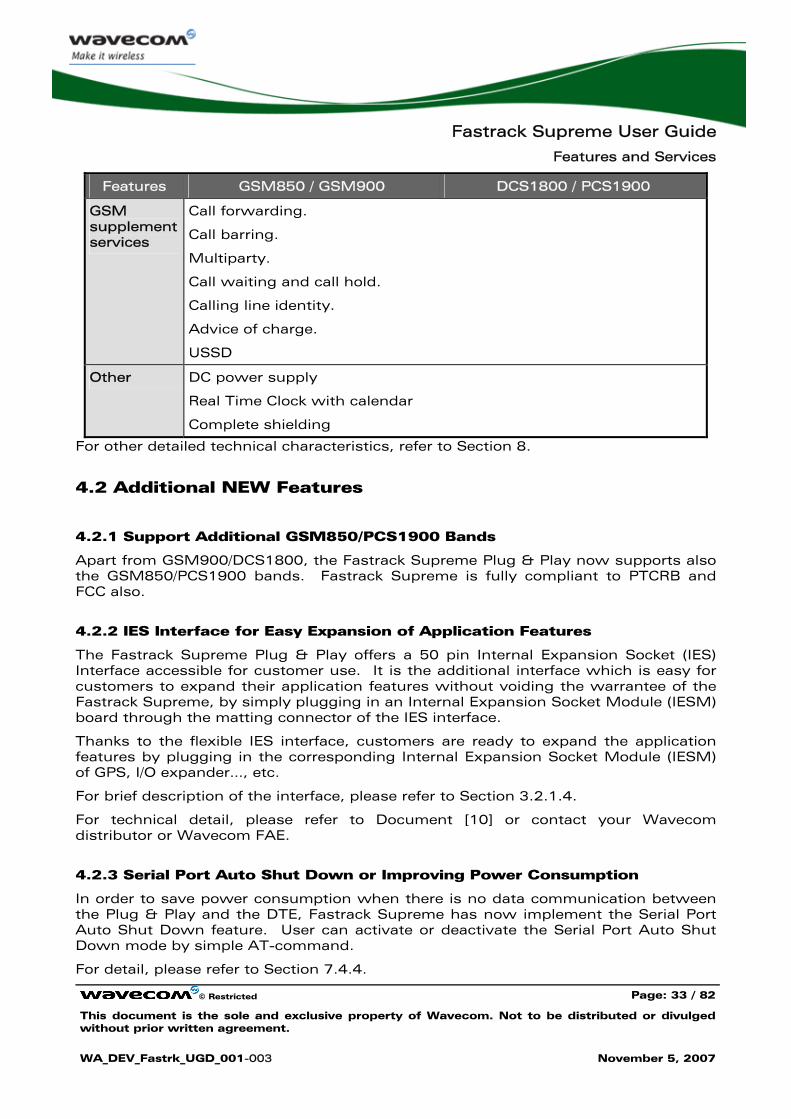
Features GSM850 / GSM900 DCS1800 / PCS1900
GSM supplement services
Call forwarding.
Call barring.
Multiparty.
Call waiting and call hold.
Calling line identity.
Advice of charge.
USSD
Other DC power supply
Real Time Clock with calendar
Complete shielding
For other detailed technical characteristics, refer to Section 8.
4.2 Additional NEW Features
4.2.1 Support Additional GSM850/PCS1900 Bands
Apart from GSM900/DCS1800, the Fastrack Supreme Plug & Play now supports also the GSM850/PCS1900 bands. Fastrack Supreme is fully compliant to PTCRB and FCC also.
4.2.2 IES Interface for Easy Expansion of Application Features
The Fastrack Supreme Plug & Play offers a 50 pin Internal Expansion Socket (IES) Interface accessible for customer use. It is the additional interface which is easy for customers to expand their application features without voiding the warrantee of the Fastrack Supreme, by simply plugging in an Internal Expansion Socket Module (IESM) board through the matting connector of the IES interface.
Thanks to the flexible IES interface, customers are ready to expand the application features by plugging in the corresponding Internal Expansion Socket Module (IESM) of GPS, I/O expander…, etc.
For brief description of the interface, please refer to Section 3.2.1.4.
For technical detail, please refer to Document [10] or contact your Wavecom distributor or Wavecom FAE.
4.2.3 Serial Port Auto Shut Down or Improving Power Consumption
In order to save power consumption when there is no data communication between the Plug & Play and the DTE, Fastrack Supreme has now implement the Serial Port Auto Shut Down feature. User can activate or deactivate the Serial Port Auto Shut Down mode by simple AT-command.
For detail, please refer to Section 7.4.4.
Fastrack Supreme User Guide
Features and Services
© Restricted Page: 34 / 82
This document is the sole and exclusive property of Wavecom. Not to be distributed or divulged without prior written agreement.
WA_DEV_Fastrk_UGD_001-003 November 5, 2007
4.2.4 Real Time Clock (RTC) for Saving Date and Time
The Fastrack Supreme has now implemented the Real Time Clock for saving date and time when the Plug & Play is unplugged from the DC power supply through the DC power cable.
For detail, please refer to Section 7.9.
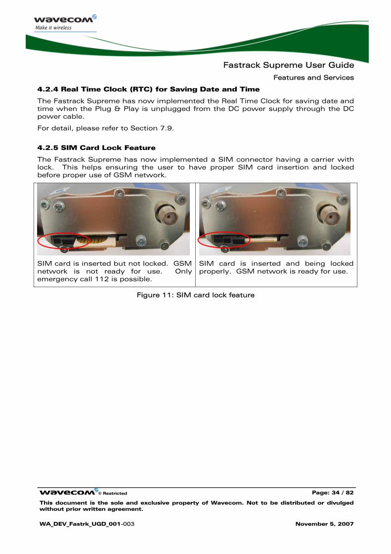
4.2.5 SIM Card Lock Feature
The Fastrack Supreme has now implemented a SIM connector having a carrier with lock. This helps ensuring the user to have proper SIM card insertion and locked before proper use of GSM network.
SIM card is inserted but not locked. GSM network is not ready for use. Only emergency call 112 is possible.
SIM card is inserted and being locked properly. GSM network is ready for use.
Figure 11: SIM card lock feature
Fastrack Supreme User Guide
Using the Fastrack Supreme Plug & Play
© Restricted Page: 35 / 82
This document is the sole and exclusive property of Wavecom. Not to be distributed or divulged without prior written agreement.
WA_DEV_Fastrk_UGD_001-003 November 5, 2007
5 Using the Fastrack Supreme Plug & Play
5.1 Getting Started
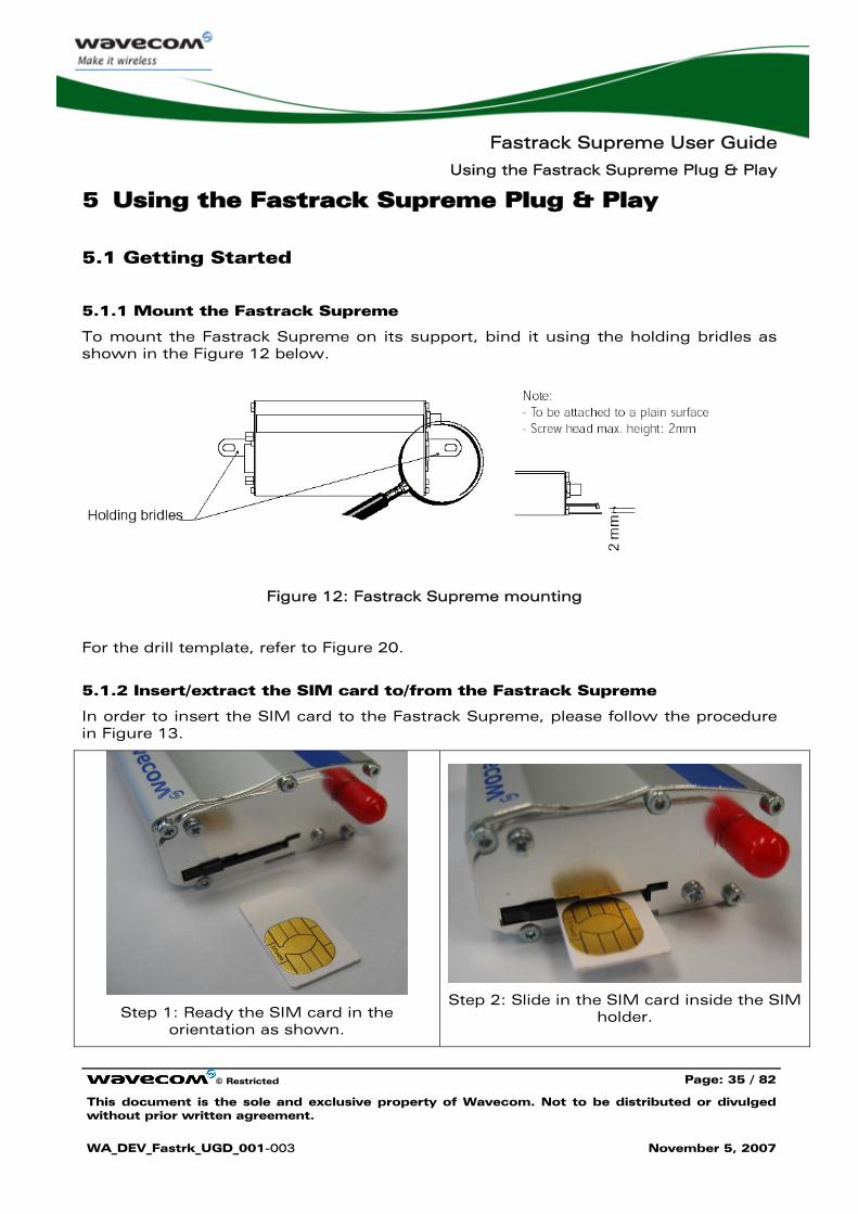
5.1.1 Mount the Fastrack Supreme
To mount the Fastrack Supreme on its support, bind it using the holding bridles as shown in the Figure 12 below.
Figure 12: Fastrack Supreme mounting
For the drill template, refer to Figure 20.
5.1.2 Insert/extract the SIM card to/from the Fastrack Supreme
In order to insert the SIM card to the Fastrack Supreme, please follow the procedure in Figure 13.
Step 1: Ready the SIM card in the orientation as shown.
Step 2: Slide in the SIM card inside the SIM holder.
Fastrack Supreme User Guide
Using the Fastrack Supreme Plug & Play
© Restricted Page: 36 / 82
This document is the sole and exclusive property of Wavecom. Not to be distributed or divulged without prior written agreement.
WA_DEV_Fastrk_UGD_001-003 November 5, 2007
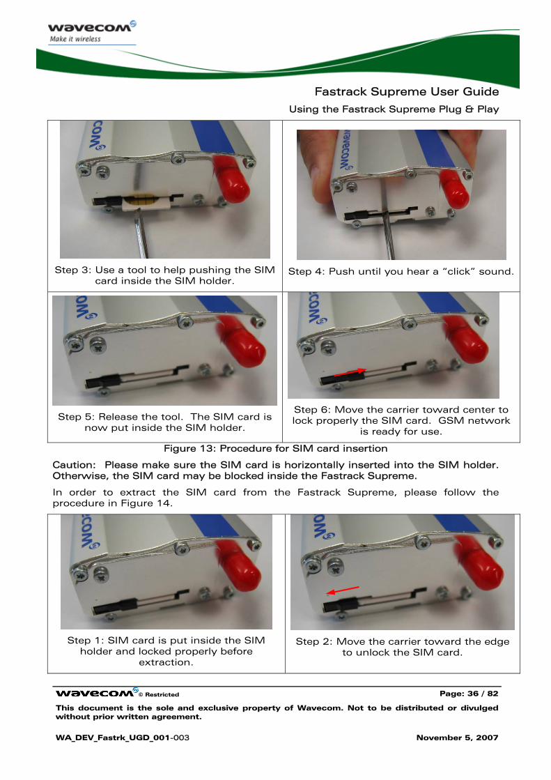
Step 3: Use a tool to help pushing the SIM card inside the SIM holder.
Step 4: Push until you hear a “click” sound.
Step 5: Release the tool. The SIM card is now put inside the SIM holder.
Step 6: Move the carrier toward center to lock properly the SIM card. GSM network
is ready for use.
Figure 13: Procedure for SIM card insertion
Caution: Please make sure the SIM card is horizontally inserted into the SIM holder. Otherwise, the SIM card may be blocked inside the Fastrack Supreme.
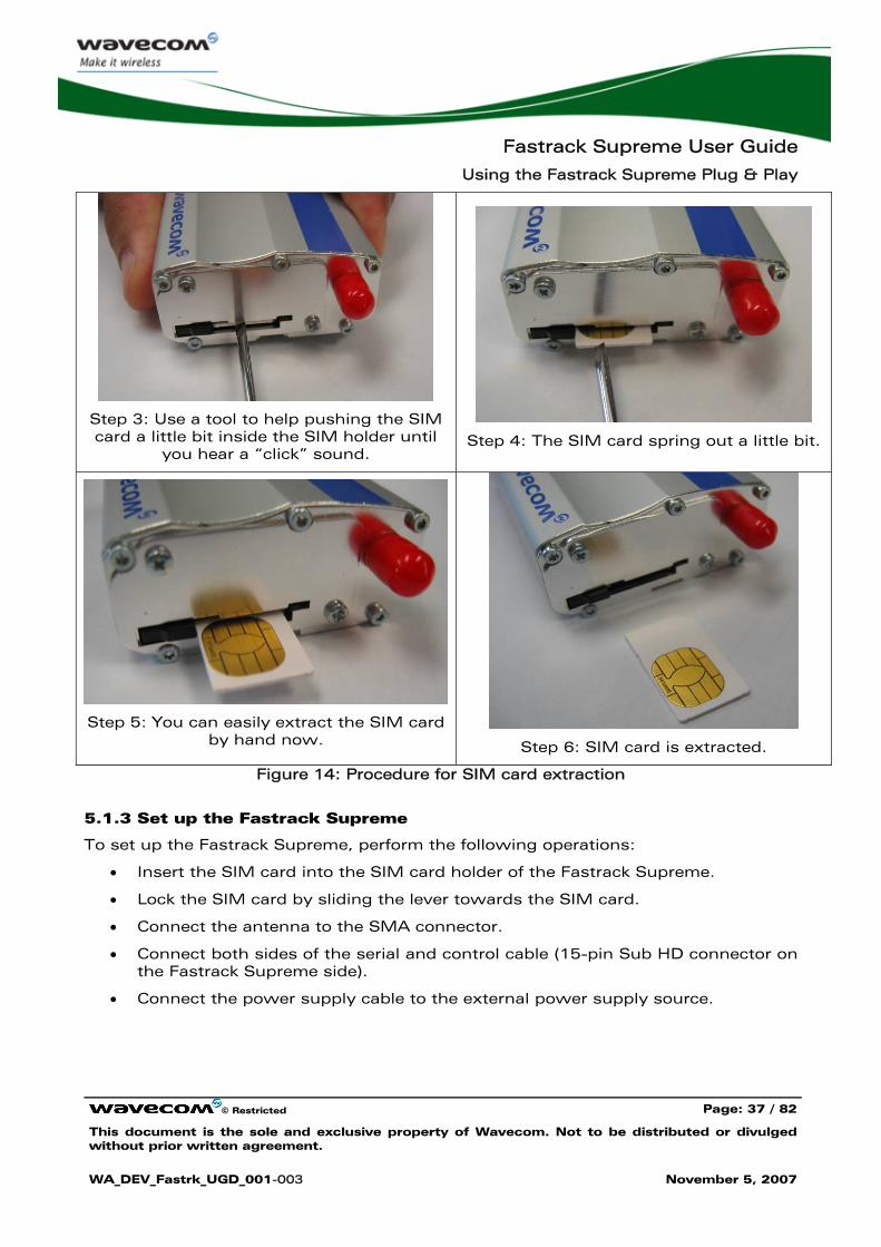
In order to extract the SIM card from the Fastrack Supreme, please follow the procedure in Figure 14.
Step 1: SIM card is put inside the SIM holder and locked properly before
extraction.
Step 2: Move the carrier toward the edge to unlock the SIM card.
Fastrack Supreme User Guide
Using the Fastrack Supreme Plug & Play
© Restricted Page: 37 / 82
This document is the sole and exclusive property of Wavecom. Not to be distributed or divulged without prior written agreement.
WA_DEV_Fastrk_UGD_001-003 November 5, 2007
Step 3: Use a tool to help pushing the SIM card a little bit inside the SIM holder until
you hear a “click” sound.
Step 4: The SIM card spring out a little bit.
Step 5: You can easily extract the SIM card by hand now.
Step 6: SIM card is extracted.
Figure 14: Procedure for SIM card extraction
5.1.3 Set up the Fastrack Supreme
To set up the Fastrack Supreme, perform the following operations:
• Insert the SIM card into the SIM card holder of the Fastrack Supreme.
• Lock the SIM card by sliding the lever towards the SIM card.
• Connect the antenna to the SMA connector.
• Connect both sides of the serial and control cable (15-pin Sub HD connector on the Fastrack Supreme side).
• Connect the power supply cable to the external power supply source.
Fastrack Supreme User Guide
Using the Fastrack Supreme Plug & Play
© Restricted Page: 38 / 82
This document is the sole and exclusive property of Wavecom. Not to be distributed or divulged without prior written agreement.
WA_DEV_Fastrk_UGD_001-003 November 5, 2007
Note:
For automotive application, it is recommended to connect the V+BATTERY line of the Fastrack Supreme directly to the battery positive terminal.
• Plug the power supply cable into the Fastrack Supreme and switch on the external power supply source.
• The Fastrack Supreme is ready to work. Refer to Section 5.10 for the description of AT commands used to configure the Fastrack Supreme.
5.1.4 Check the communication with the Fastrack Supreme
To check the communication with the Fastrack Supreme, do the following operations:
• Connect the RS232 link between the DTE (port COM) and the Fastrack Supreme (DCE).
• Configure the RS232 port of the DTE as follows:
Bits per second: 115.200 bps,
Data bits: 8,
Parity: None,
Stop bits: 1,
Flow control: hardware.
• Using a communication software such as a HyperTerminal, enter the AT↵ command. The response of the Fastrack Supreme must be OK displayed in the HyperTerminal window.
• If the communication cannot be established with the Fastrack Supreme, do the following:
Check the RS232 connection between the DTE and the Fastrack Supreme (DCE),
Check the configuration of the port COM used on the DTE.
• Example of AT commands which can be used after getting started the Fastrack Supreme:
AT+CGMI: Fastrack Supreme answer is "WAVECOM MODEM" when serial link is OK.
AT+CPIN=xxxx: to enter a PIN code xxxx (if activated).
AT+CSQ: to verify the received signal strength.
AT+CREG?: to verify the registration of the Fastrack Supreme Plug & Play on the network.
ATD<phone number>: to initiate a voice call.
ATH: to hang up (end of call).
Fastrack Supreme User Guide
Using the Fastrack Supreme Plug & Play
© Restricted Page: 39 / 82
This document is the sole and exclusive property of Wavecom. Not to be distributed or divulged without prior written agreement.
WA_DEV_Fastrk_UGD_001-003 November 5, 2007
For further information on these AT commands and their associated parameters, refer to "AT Commands Interface Guide" [7].
5.1.5 Reset the Fastrack Supreme
To reset the Fastrack Supreme, a hardware reset signal is available on pin 14 of the Sub HD 15-pin connector (RESET).
The Fastrack Supreme reset is carried out when this pin is low for at least 200 μs.
Warning This signal has to be considered as an emergency reset only. For further details on the Fastrack Supreme reset, refer to Section 7.7.
5.2 Specific Recommendations when Using the Fastrack Supreme on Trucks
Warning: The power supply connection of the Fastrack Supreme must NEVER be directly connected to the truck battery.
5.2.1 Recommended Power Supply Connection on Trucks
All trucks have a circuit breaker on the exterior of the cabin. The circuit breaker is used for safety reasons: if a fire blazes in the trucks, (for example, on the wiring trunk) the driver may cut the current source to avoid any damage (explosion). The circuit breaker is connected to the truck ground, most often associated with the fuse box.
Most of truck circuit breakers do not cut the Positive Supply line of the battery, but cut the ground line of the later.
Fastrack Supreme User Guide
Using the Fastrack Supreme Plug & Play
© Restricted Page: 40 / 82
This document is the sole and exclusive property of Wavecom. Not to be distributed or divulged without prior written agreement.
WA_DEV_Fastrk_UGD_001-003 November 5, 2007
FASTRACK Suprem e
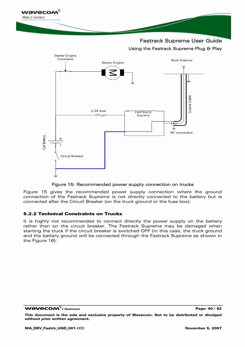
Figure 15: Recommended power supply connection on trucks
Figure 15 gives the recommended power supply connection where the ground connection of the Fastrack Supreme is not directly connected to the battery but is connected after the Circuit Breaker (on the truck ground or the fuse box).
5.2.2 Technical Constraints on Trucks
It is highly not recommended to connect directly the power supply on the battery rather than on the circuit breaker. The Fastrack Supreme may be damaged when starting the truck if the circuit breaker is switched OFF (in this case, the truck ground and the battery ground will be connected through the Fastrack Supreme as shown in the Figure 16).
Fastrack Supreme User Guide
Using the Fastrack Supreme Plug & Play
© Restricted Page: 41 / 82
This document is the sole and exclusive property of Wavecom. Not to be distributed or divulged without prior written agreement.
WA_DEV_Fastrk_UGD_001-003 November 5, 2007
FASTRACK Supreme
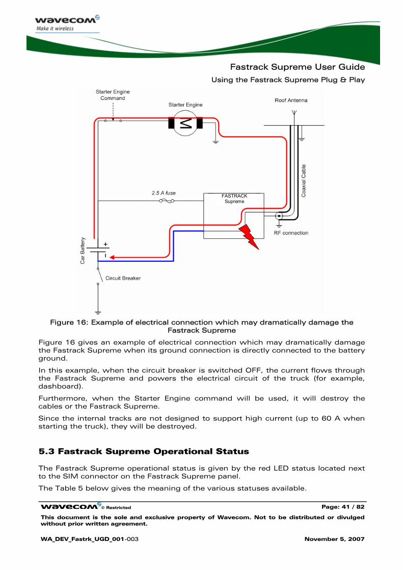
Figure 16: Example of electrical connection which may dramatically damage the Fastrack Supreme
Figure 16 gives an example of electrical connection which may dramatically damage the Fastrack Supreme when its ground connection is directly connected to the battery ground.
In this example, when the circuit breaker is switched OFF, the current flows through the Fastrack Supreme and powers the electrical circuit of the truck (for example, dashboard).
Furthermore, when the Starter Engine command will be used, it will destroy the cables or the Fastrack Supreme.
Since the internal tracks are not designed to support high current (up to 60 A when starting the truck), they will be destroyed.
5.3 Fastrack Supreme Operational Status
The Fastrack Supreme operational status is given by the red LED status located next to the SIM connector on the Fastrack Supreme panel.
The Table 5 below gives the meaning of the various statuses available.
Fastrack Supreme User Guide
Using the Fastrack Supreme Plug & Play
© Restricted Page: 42 / 82
This document is the sole and exclusive property of Wavecom. Not to be distributed or divulged without prior written agreement.
WA_DEV_Fastrk_UGD_001-003 November 5, 2007
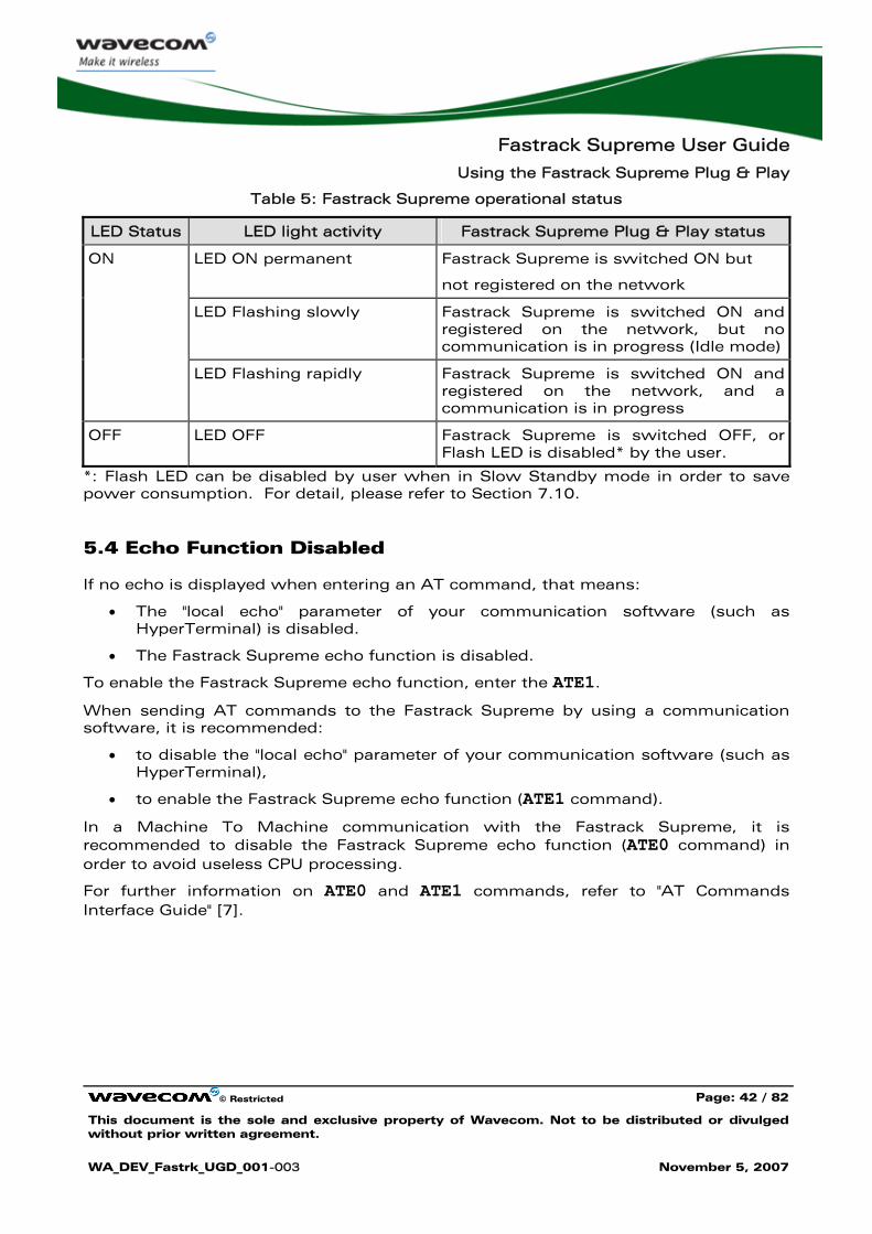
Table 5: Fastrack Supreme operational status
LED Status LED light activity Fastrack Supreme Plug & Play status
LED ON permanent Fastrack Supreme is switched ON but
not registered on the network
LED Flashing slowly Fastrack Supreme is switched ON and registered on the network, but no communication is in progress (Idle mode)
ON
LED Flashing rapidly Fastrack Supreme is switched ON and registered on the network, and a communication is in progress
OFF LED OFF Fastrack Supreme is switched OFF, or Flash LED is disabled* by the user.
*: Flash LED can be disabled by user when in Slow Standby mode in order to save power consumption. For detail, please refer to Section 7.10.
5.4 Echo Function Disabled
If no echo is displayed when entering an AT command, that means:
• The "local echo" parameter of your communication software (such as HyperTerminal) is disabled.
• The Fastrack Supreme echo function is disabled.
To enable the Fastrack Supreme echo function, enter the ATE1.
When sending AT commands to the Fastrack Supreme by using a communication software, it is recommended:
• to disable the "local echo" parameter of your communication software (such as HyperTerminal),
• to enable the Fastrack Supreme echo function (ATE1 command).
In a Machine To Machine communication with the Fastrack Supreme, it is recommended to disable the Fastrack Supreme echo function (ATE0 command) in order to avoid useless CPU processing.
For further information on ATE0 and ATE1 commands, refer to "AT Commands Interface Guide" [7].
Fastrack Supreme User Guide
Using the Fastrack Supreme Plug & Play
© Restricted Page: 43 / 82
This document is the sole and exclusive property of Wavecom. Not to be distributed or divulged without prior written agreement.
WA_DEV_Fastrk_UGD_001-003 November 5, 2007
5.5 Verify the Received Signal Strength
The Fastrack Supreme establishes a call only if the received signal is sufficiently strong.
To verify the received signal strength, do the following operations:
• Using a communication software such as HyperTerminal, enter the AT command AT+CSQ. The response returned has the following format: +CSQ: <rssi>,<ber> with:
• <rssi> = received signal strength indication,
• <ber> = channel bit error rate.
• Verify the <rssi> value returned using the Table 6 below.
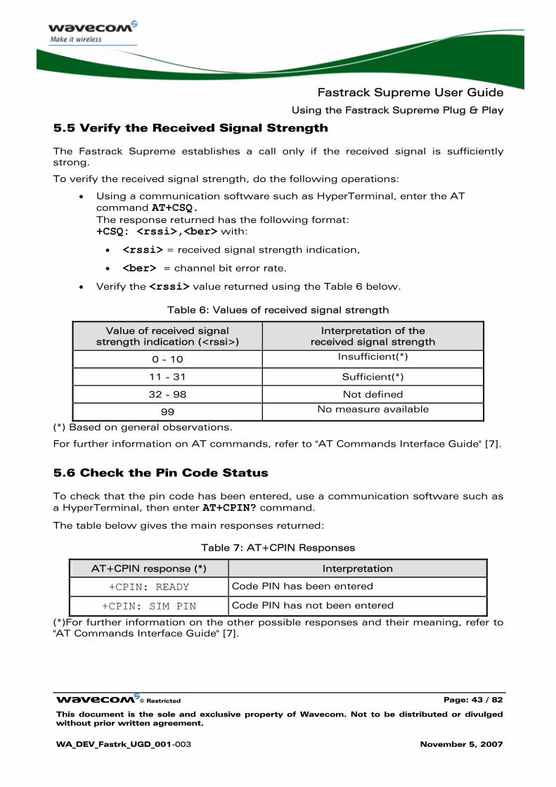
Table 6: Values of received signal strength
Value of received signal strength indication (<rssi>)
Interpretation of the received signal strength
0 - 10 Insufficient(*)
11 - 31 Sufficient(*)
32 - 98 Not defined
99 No measure available
(*) Based on general observations.
For further information on AT commands, refer to "AT Commands Interface Guide" [7].
5.6 Check the Pin Code Status
To check that the pin code has been entered, use a communication software such as a HyperTerminal, then enter AT+CPIN? command.
The table below gives the main responses returned:
Table 7: AT+CPIN Responses
AT+CPIN response (*) Interpretation
+CPIN: READY Code PIN has been entered
+CPIN: SIM PIN Code PIN has not been entered
(*)For further information on the other possible responses and their meaning, refer to "AT Commands Interface Guide" [7].
Fastrack Supreme User Guide
Using the Fastrack Supreme Plug & Play
© Restricted Page: 44 / 82
This document is the sole and exclusive property of Wavecom. Not to be distributed or divulged without prior written agreement.
WA_DEV_Fastrk_UGD_001-003 November 5, 2007
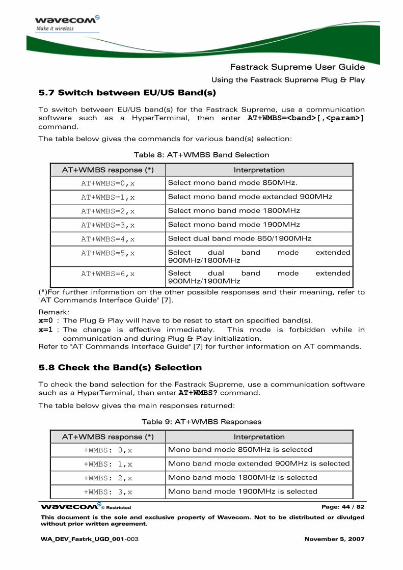
5.7 Switch between EU/US Band(s)
To switch between EU/US band(s) for the Fastrack Supreme, use a communication software such as a HyperTerminal, then enter AT+WMBS=<band>[,<param>] command.
The table below gives the commands for various band(s) selection:
Table 8: AT+WMBS Band Selection
AT+WMBS response (*) Interpretation
AT+WMBS=0,x Select mono band mode 850MHz.
AT+WMBS=1,x Select mono band mode extended 900MHz
AT+WMBS=2,x Select mono band mode 1800MHz
AT+WMBS=3,x Select mono band mode 1900MHz
AT+WMBS=4,x Select dual band mode 850/1900MHz
AT+WMBS=5,x Select dual band mode extended 900MHz/1800MHz
AT+WMBS=6,x Select dual band mode extended 900MHz/1900MHz
(*)For further information on the other possible responses and their meaning, refer to "AT Commands Interface Guide" [7].
Remark: x=0 : The Plug & Play will have to be reset to start on specified band(s). x=1 : The change is effective immediately. This mode is forbidden while in
communication and during Plug & Play initialization. Refer to "AT Commands Interface Guide" [7] for further information on AT commands.
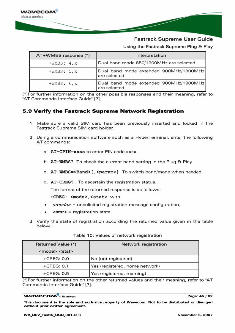
5.8 Check the Band(s) Selection
To check the band selection for the Fastrack Supreme, use a communication software such as a HyperTerminal, then enter AT+WMBS? command.
The table below gives the main responses returned:
Table 9: AT+WMBS Responses
AT+WMBS response (*) Interpretation
+WMBS: 0,x Mono band mode 850MHz is selected
+WMBS: 1,x Mono band mode extended 900MHz is selected
+WMBS: 2,x Mono band mode 1800MHz is selected
+WMBS: 3,x Mono band mode 1900MHz is selected
Fastrack Supreme User Guide
Using the Fastrack Supreme Plug & Play
© Restricted Page: 45 / 82
This document is the sole and exclusive property of Wavecom. Not to be distributed or divulged without prior written agreement.
WA_DEV_Fastrk_UGD_001-003 November 5, 2007
AT+WMBS response (*) Interpretation
+WMBS: 4,x Dual band mode 850/1900MHz are selected
+WMBS: 5,x Dual band mode extended 900MHz/1800MHz are selected
+WMBS: 6,x Dual band mode extended 900MHz/1900MHz are selected
(*)For further information on the other possible responses and their meaning, refer to "AT Commands Interface Guide" [7].
5.9 Verify the Fastrack Supreme Network Registration
1. Make sure a valid SIM card has been previously inserted and locked in the Fastrack Supreme SIM card holder.
2. Using a communication software such as a HyperTerminal, enter the following AT commands:
a. AT+CPIN=xxxx to enter PIN code xxxx.
b. AT+WMBS? To check the current band setting in the Plug & Play
c. AT+WMBS=<Band>[,<param>] To switch band/mode when needed
d. AT+CREG?. To ascertain the registration status.
The format of the returned response is as follows:
+CREG: <mode>,<stat> with:
• <mode> = unsolicited registration message configuration,
• <stat> = registration state.
3. Verify the state of registration according the returned value given in the table below.
Table 10: Values of network registration
Returned Value (*)
<mode>,<stat>
Network registration
+CREG: 0,0 No (not registered)
+CREG: 0,1 Yes (registered, home network)
+CREG: 0,5 Yes (registered, roaming)
(*)For further information on the other returned values and their meaning, refer to "AT Commands Interface Guide" [7].
Fastrack Supreme User Guide
Using the Fastrack Supreme Plug & Play
© Restricted Page: 46 / 82
This document is the sole and exclusive property of Wavecom. Not to be distributed or divulged without prior written agreement.
WA_DEV_Fastrk_UGD_001-003 November 5, 2007
If the Fastrack Supreme is not registered, perform the following procedure:
• Check the connection between the Fastrack Supreme and the antenna.
• Verify the signal strength to determine the received signal strength (refer to Section 5.5).
Note: For information on AT command relating to the network registration in GPRS mode, and in particular: CGREG, CGCLASS, CGATT, refer to "AT Commands Interface Guide" [7].
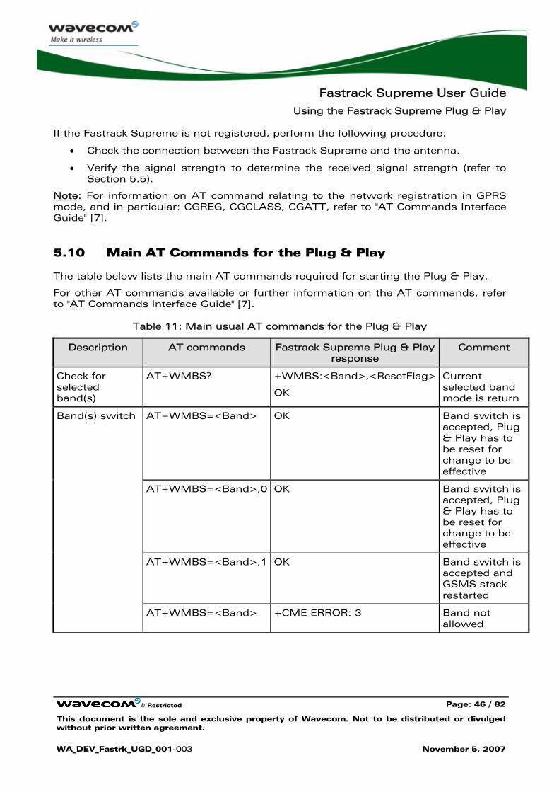
5.10 Main AT Commands for the Plug & Play
The table below lists the main AT commands required for starting the Plug & Play.
For other AT commands available or further information on the AT commands, refer to "AT Commands Interface Guide" [7].
Table 11: Main usual AT commands for the Plug & Play
Description AT commands Fastrack Supreme Plug & Play response
Comment
Check for selected band(s)
AT+WMBS? +WMBS:<Band>,<ResetFlag>
OK
Current selected band mode is return
AT+WMBS=<Band> OK Band switch is accepted, Plug & Play has to be reset for change to be effective
AT+WMBS=<Band>,0 OK Band switch is accepted, Plug & Play has to be reset for change to be effective
AT+WMBS=<Band>,1 OK Band switch is accepted and GSMS stack restarted
Band(s) switch
AT+WMBS=<Band> +CME ERROR: 3 Band not allowed
Fastrack Supreme User Guide
Using the Fastrack Supreme Plug & Play
© Restricted Page: 47 / 82
This document is the sole and exclusive property of Wavecom. Not to be distributed or divulged without prior written agreement.
WA_DEV_Fastrk_UGD_001-003 November 5, 2007
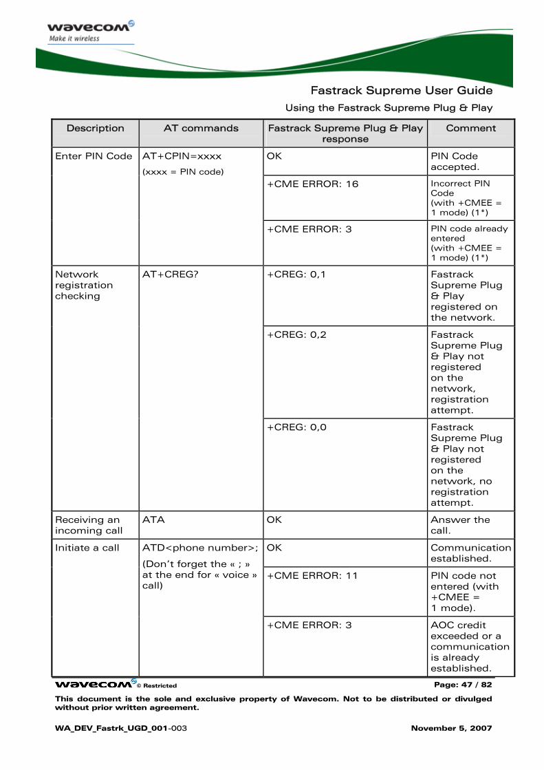
Description AT commands Fastrack Supreme Plug & Play response
Comment
OK PIN Code accepted.
+CME ERROR: 16 Incorrect PIN Code (with +CMEE = 1 mode) (1*)
Enter PIN Code AT+CPIN=xxxx
(xxxx = PIN code)
+CME ERROR: 3 PIN code already entered (with +CMEE = 1 mode) (1*)
+CREG: 0,1 Fastrack Supreme Plug & Play registered on the network.
+CREG: 0,2 Fastrack Supreme Plug & Play not registered on the network, registration attempt.
Network registration checking
AT+CREG?
+CREG: 0,0 Fastrack Supreme Plug & Play not registered on the network, no registration attempt.
Receiving an incoming call
ATA OK Answer the call.
OK Communication established.
+CME ERROR: 11 PIN code not entered (with +CMEE = 1 mode).
Initiate a call ATD<phone number>;
(Don’t forget the « ; » at the end for « voice » call)
+CME ERROR: 3 AOC credit exceeded or a communication is already established.
Fastrack Supreme User Guide
Using the Fastrack Supreme Plug & Play
© Restricted Page: 48 / 82
This document is the sole and exclusive property of Wavecom. Not to be distributed or divulged without prior written agreement.
WA_DEV_Fastrk_UGD_001-003 November 5, 2007
Description AT commands Fastrack Supreme Plug & Play response
Comment
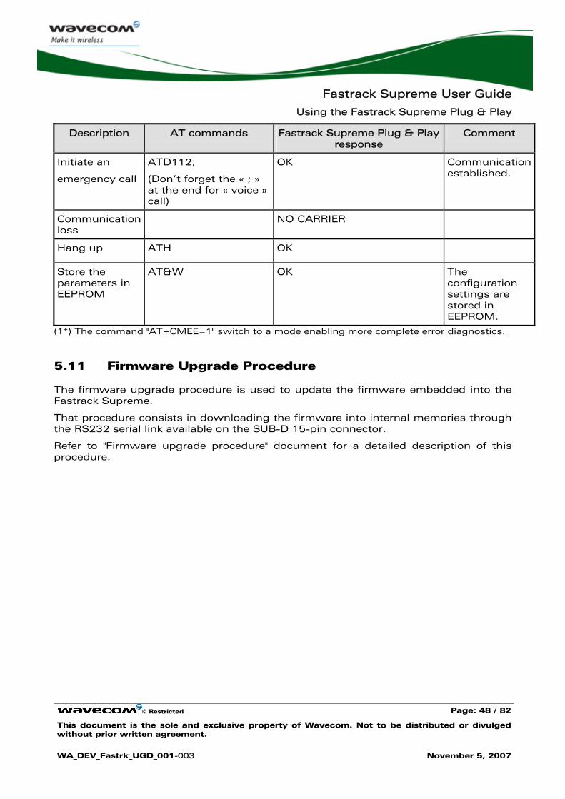
Initiate an
emergency call
ATD112;
(Don’t forget the « ; » at the end for « voice » call)
OK Communication established.
Communication loss
NO CARRIER
Hang up ATH OK
Store the parameters in EEPROM
AT&W OK The configuration settings are stored in EEPROM.
(1*) The command "AT+CMEE=1" switch to a mode enabling more complete error diagnostics.
5.11 Firmware Upgrade Procedure
The firmware upgrade procedure is used to update the firmware embedded into the Fastrack Supreme.
That procedure consists in downloading the firmware into internal memories through the RS232 serial link available on the SUB-D 15-pin connector.
Refer to "Firmware upgrade procedure" document for a detailed description of this procedure.
Fastrack Supreme User Guide
Troubleshooting
© Restricted Page: 49 / 82
This document is the sole and exclusive property of Wavecom. Not to be distributed or divulged without prior written agreement.
WA_DEV_Fastrk_UGD_001-003 November 5, 2007
6 Troubleshooting
This section of the document describes possible problems encountered when using the Fastrack Supreme and their solutions.
To review other troubleshooting information, refer the ‘FAQs’ (Frequently Asked Questions) page at www.wavecom.com/fastracksupreme.
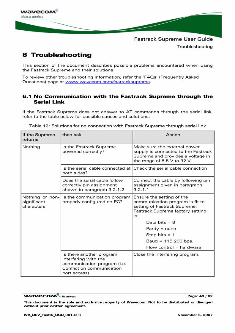
6.1 No Communication with the Fastrack Supreme through the Serial Link
If the Fastrack Supreme does not answer to AT commands through the serial link, refer to the table below for possible causes and solutions.
Table 12: Solutions for no connection with Fastrack Supreme through serial link
If the Supreme returns
then ask Action
Is the Fastrack Supreme powered correctly?
Make sure the external power supply is connected to the Fastrack Supreme and provides a voltage in the range of 5.5 V to 32 V.
Is the serial cable connected at both sides?
Check the serial cable connection
Nothing
Does the serial cable follow correctly pin assignment shown in paragraph 3.2.1.2.
Connect the cable by following pin assignment given in paragraph 3.2.1.1.
Is the communication program properly configured on PC?
Ensure the setting of the communication program is fit to setting of Fastrack Supreme. Fastrack Supreme factory setting is:
Data bits = 8
Parity = none
Stop bits = 1
Baud = 115 200 bps.
Flow control = hardware
Nothing or non-significant characters
Is there another program interfering with the communication program (i.e. Conflict on communication port access)
Close the interfering program.
Fastrack Supreme User Guide
Troubleshooting
© Restricted Page: 50 / 82
This document is the sole and exclusive property of Wavecom. Not to be distributed or divulged without prior written agreement.
WA_DEV_Fastrk_UGD_001-003 November 5, 2007
6.2 Receiving "ERROR" Message
The Fastrack Supreme returns an "ERROR" message (in reply to an AT command) in the following cases:
• AT command syntax is incorrect: check the command syntax (refer to "AT Commands Interface Guide" [7]),
• AT command syntax is correct, but transmitted with wrong parameters:
• Enter the AT+CMEE=1 command in order to change the error report method to the verbose method, which includes the error codes.
• Enter again the AT command which previously caused the reception of "ERROR" message in order to get the Mobile Equipment error code.
When the verbose error report method is enabled, the response of the Fastrack Supreme in case of error is as follows:
• Either +CME ERROR: <error result code>,
• Or +CMS ERROR: <error result code>.
Refer to "AT Commands Interface Guide" [7] for error result code description and further details on the AT +CMEE command.
Note: It is strongly recommended to always enable the verbose error report method to get the Mobile Equipment error code (enter AT +CMEE=1 command).
6.3 Receiving "NO CARRIER" Message
If the Fastrack Supreme returns a "NO CARRIER" message upon an attempted call (voice or data), then refer to the table below for possible causes and solutions.
Fastrack Supreme User Guide
Troubleshooting
© Restricted Page: 51 / 82
This document is the sole and exclusive property of Wavecom. Not to be distributed or divulged without prior written agreement.
WA_DEV_Fastrk_UGD_001-003 November 5, 2007
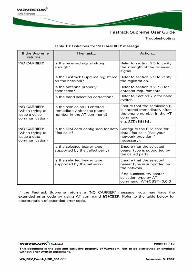
Table 13: Solutions for "NO CARRIER" message
If the Supreme returns…
Then ask… Action…
Is the received signal strong enough?
Refer to section 5.5 to verify the strength of the received signal.
Is the Fastrack Supreme registered on the network?
Refer to section 5.9 to verify the registration.
Is the antenna properly connected?
Refer to section 8.2.7.3 for antenna requirements.
"NO CARRIER"
Is the band selection correction? Refer to Section 7.2 for band switch
"NO CARRIER" (when trying to issue a voice communication)
Is the semicolon (;) entered immediately after the phone number in the AT command?
Ensure that the semicolon (;) is entered immediately after the phone number in the AT command. e.g. ATD######;
Is the SIM card configured for data / fax calls?
Configure the SIM card for data / fax calls (Ask your network provider if necessary).
Is the selected bearer type supported by the called party?
Ensure that the selected bearer type is supported by the called party.
"NO CARRIER" (when trying to issue a data communication)
Is the selected bearer type supported by the network?
Ensure that the selected bearer type is supported by the network.
If no success, try bearer selection type by AT command: AT+CBST=0,0,3
If the Fastrack Supreme returns a "NO CARRIER" message, you may have the extended error code by using AT command AT+CEER. Refer to the table below for interpretation of extended error code.
Fastrack Supreme User Guide
Troubleshooting
© Restricted Page: 52 / 82
This document is the sole and exclusive property of Wavecom. Not to be distributed or divulged without prior written agreement.
WA_DEV_Fastrk_UGD_001-003 November 5, 2007
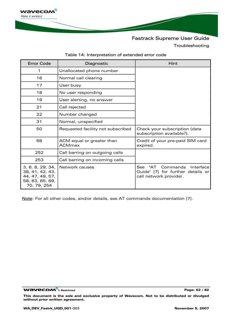
Table 14: Interpretation of extended error code
Error Code Diagnostic Hint
1 Unallocated phone number
16 Normal call clearing
17 User busy
18 No user responding
19 User alerting, no answer
21 Call rejected
22 Number changed
31 Normal, unspecified
50 Requested facility not subscribed Check your subscription (data subscription available?).
68 ACM equal or greater than ACMmax
Credit of your pre-paid SIM card expired.
252 Call barring on outgoing calls
253 Call barring on incoming calls
3, 6, 8, 29, 34, 38, 41, 42, 43, 44, 47, 49, 57, 58, 63, 65, 69,
70, 79, 254
Network causes
See "AT Commands Interface Guide" [7] for further details or call network provider.
Note: For all other codes, and/or details, see AT commands documentation [7].
Fastrack Supreme User Guide
Functional Description
© Restricted Page: 53 / 82
This document is the sole and exclusive property of Wavecom. Not to be distributed or divulged without prior written agreement.
WA_DEV_Fastrk_UGD_001-003 November 5, 2007
7 Functional Description
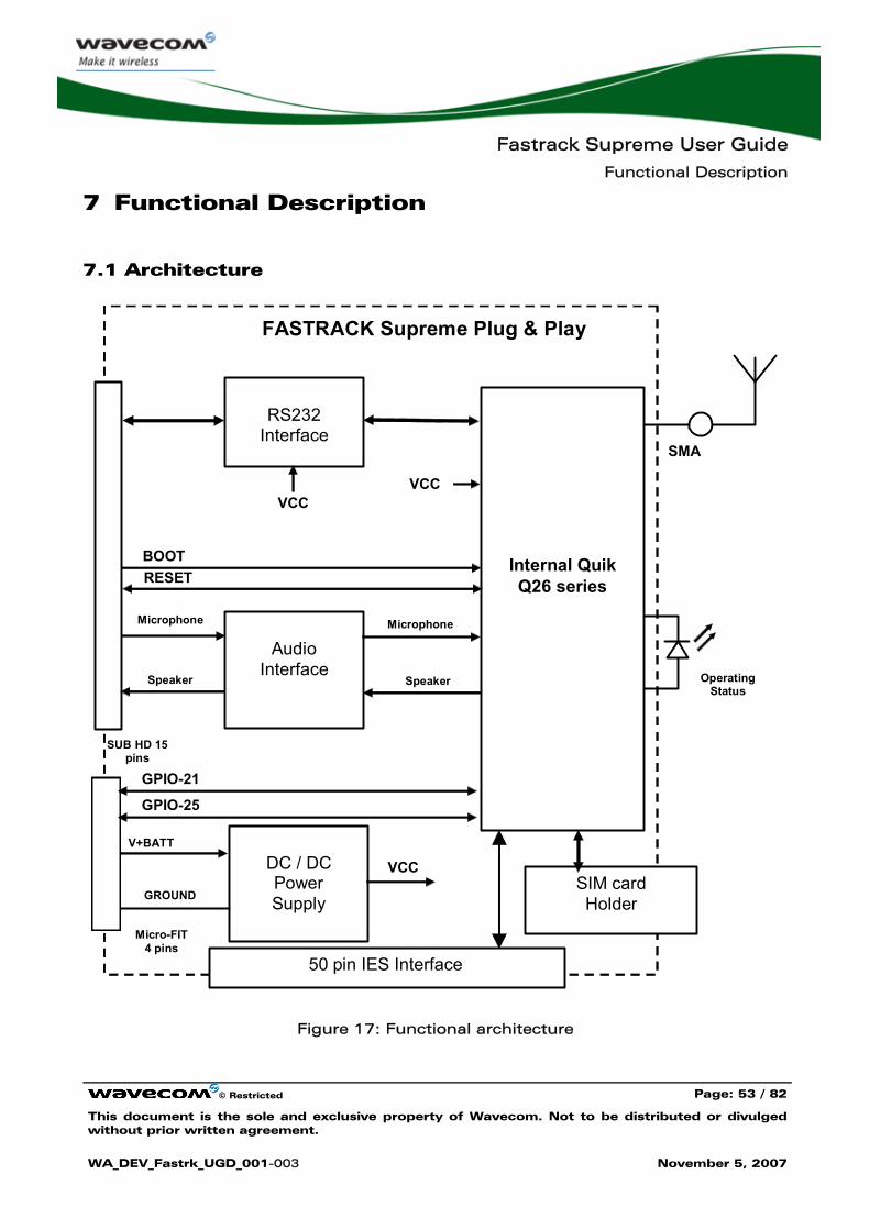
7.1 Architecture
Internal Quik Q26 series
RS232
Interface SMA
Audio
Interface
DC / DC Power Supply
BOOT RESET
V+BATT
GROUND
Micro-FIT 4 pins
SUB HD 15 pins
VCC
Microphone Microphone
Speaker Speaker
VCC VCC
SIM card Holder
Operating Status
FASTRACK Supreme Plug & Play
GPIO-21
GPIO-25
50 pin IES Interface
Figure 17: Functional architecture
Fastrack Supreme User Guide
Functional Description
© Restricted Page: 54 / 82
This document is the sole and exclusive property of Wavecom. Not to be distributed or divulged without prior written agreement.
WA_DEV_Fastrk_UGD_001-003 November 5, 2007
7.2 EU and US Bands
7.2.1 General Presentation
The Fastrack Supreme is a quad band Plug & Play. It supports either EU bands (EGSM900/DCS1800) or US bands (GSM850/ PCS1900), depending on the band setting within the Plug & Play. Users are free to switch between EU bands and US bands by simple AT commands when the selected bands are supported.
7.2.2 AT COMMAND for Bands Switch
EU/US band is easily switched/checked by AT command AT+WMBS.
For detail, please refer to Section 5.7 and 5.8.
7.3 Power Supply
7.3.1 General Presentation
The Fastrack Supreme is supplied by an external DC voltage (V+BATTERY) from +5.5 V to +32 V at 2.2 A.
Main regulation is made with an internal DC/DC converter in order to supply all the internal functions with a DC voltage.
Correct operation of the Fastrack Supreme in communication mode is not guaranteed if input voltage (V+BATTERY) falls below 5.5 V.
Note: The minimum input voltage specified here is at the Fastrack Supreme input. Be careful of the input voltage decrease caused by the power cable. See paragraph 8.2.1 for more information.
7.3.2 Protections
The Fastrack Supreme is protected by a 800 mA / 250 V fuse directly bonded on the power supply cable.
The Fastrack Supreme is also protected against voltage over +32 V.
Filtering guarantees:
• EMI/RFI protection in input and output,
• Signal smoothing.
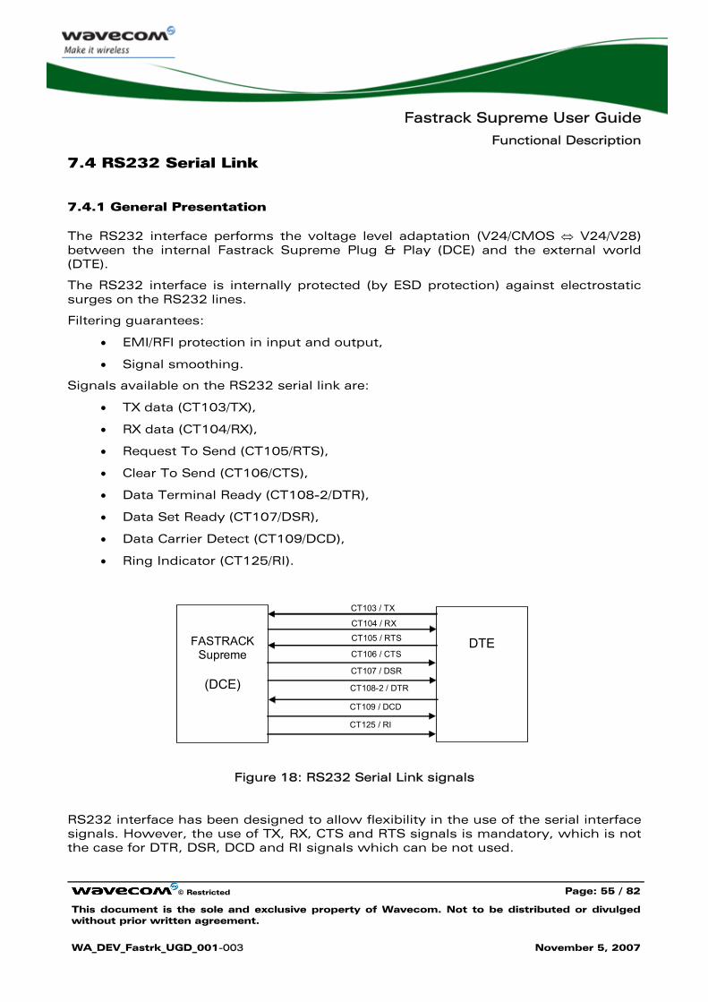
Fastrack Supreme User Guide
Functional Description
© Restricted Page: 55 / 82
This document is the sole and exclusive property of Wavecom. Not to be distributed or divulged without prior written agreement.
WA_DEV_Fastrk_UGD_001-003 November 5, 2007
7.4 RS232 Serial Link
7.4.1 General Presentation
The RS232 interface performs the voltage level adaptation (V24/CMOS ⇔ V24/V28) between the internal Fastrack Supreme Plug & Play (DCE) and the external world (DTE).
The RS232 interface is internally protected (by ESD protection) against electrostatic surges on the RS232 lines.
Filtering guarantees:
• EMI/RFI protection in input and output,
• Signal smoothing.
Signals available on the RS232 serial link are:
• TX data (CT103/TX),
• RX data (CT104/RX),
• Request To Send (CT105/RTS),
• Clear To Send (CT106/CTS),
• Data Terminal Ready (CT108-2/DTR),
• Data Set Ready (CT107/DSR),
• Data Carrier Detect (CT109/DCD),
• Ring Indicator (CT125/RI).
FASTRACK
Supreme
(DCE)
DTE
CT103 / TX
CT108-2 / DTR
CT105 / RTS
CT104 / RX
CT106 / CTS
CT107 / DSR
CT109 / DCD
CT125 / RI
Figure 18: RS232 Serial Link signals
RS232 interface has been designed to allow flexibility in the use of the serial interface signals. However, the use of TX, RX, CTS and RTS signals is mandatory, which is not the case for DTR, DSR, DCD and RI signals which can be not used.
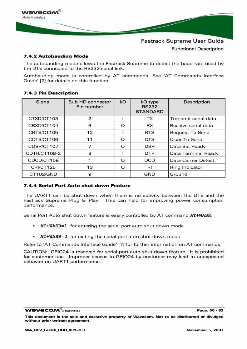
Fastrack Supreme User Guide
Functional Description
© Restricted Page: 56 / 82
This document is the sole and exclusive property of Wavecom. Not to be distributed or divulged without prior written agreement.
WA_DEV_Fastrk_UGD_001-003 November 5, 2007
7.4.2 Autobauding Mode
The autobauding mode allows the Fastrack Supreme to detect the baud rate used by the DTE connected to the RS232 serial link.
Autobauding mode is controlled by AT commands. See "AT Commands Interface Guide" [7] for details on this function.
7.4.3 Pin Description
Signal Sub HD connector Pin number
I/O I/O type RS232
STANDARD
Description
CTXD/CT103 2 I TX Transmit serial data
CRXD/CT104 6 O RX Receive serial data
CRTS/CT105 12 I RTS Request To Send
CCTS/CT106 11 O CTS Clear To Send
CDSR/CT107 7 O DSR Data Set Ready
CDTR/CT108-2 8 I DTR Data Terminal Ready
CDCD/CT109 1 O DCD Data Carrier Detect
CRI/CT125 13 O RI Ring Indicator
CT102/GND 9 GND Ground
7.4.4 Serial Port Auto shut down Feature
The UART1 can be shut down when there is no activity between the DTE and the Fastrack Supreme Plug & Play. This can help for improving power consumption performance.
Serial Port Auto shut down feature is easily controlled by AT command AT+WASR.
AT+WASR=1 for entering the serial port auto shut down mode
AT+WASR=0 for exiting the serial port auto shut down mode
Refer to "AT Commands Interface Guide" [7] for further information on AT commands.
CAUTION: GPIO24 is reserved for serial port auto shut down feature. It is prohibited for customer use. Improper access to GPIO24 by customer may lead to unexpected behavior on UART1 performance.
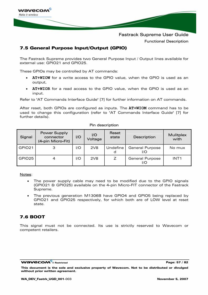
Fastrack Supreme User Guide
Functional Description
© Restricted Page: 57 / 82
This document is the sole and exclusive property of Wavecom. Not to be distributed or divulged without prior written agreement.
WA_DEV_Fastrk_UGD_001-003 November 5, 2007
7.5 General Purpose Input/Output (GPIO)
The Fastrack Supreme provides two General Purpose Input / Output lines available for external use: GPIO21 and GPIO25.
These GPIOs may be controlled by AT commands:
• AT+WIOW for a write access to the GPIO value, when the GPIO is used as an output,
• AT+WIOR for a read access to the GPIO value, when the GPIO is used as an input.
Refer to "AT Commands Interface Guide" [7] for further information on AT commands.
After reset, both GPIOs are configured as inputs. The AT+WIOM command has to be used to change this configuration (refer to "AT Commands Interface Guide" [7] for further details).
Pin description
Signal Power Supply
connector (4-pin Micro-Fit)
I/O I/O Voltage
Reset state Description Mulitplex
with
GPIO21 3 I/O 2V8 Undefined
General Purpose I/O
No mux
GPIO25 4 I/O 2V8 Z General Purpose I/O
INT1
Notes:
• The power supply cable may need to be modified due to the GPIO signals (GPIO21 & GPIO25) available on the 4-pin Micro-FIT connector of the Fastrack Supreme.
• The previous generation M1306B have GPIO4 and GPIO5 being replaced by GPIO21 and GPIO25 respectively, for which both are of LOW level at reset state.
7.6 BOOT
This signal must not be connected. Its use is strictly reserved to Wavecom or competent retailers.
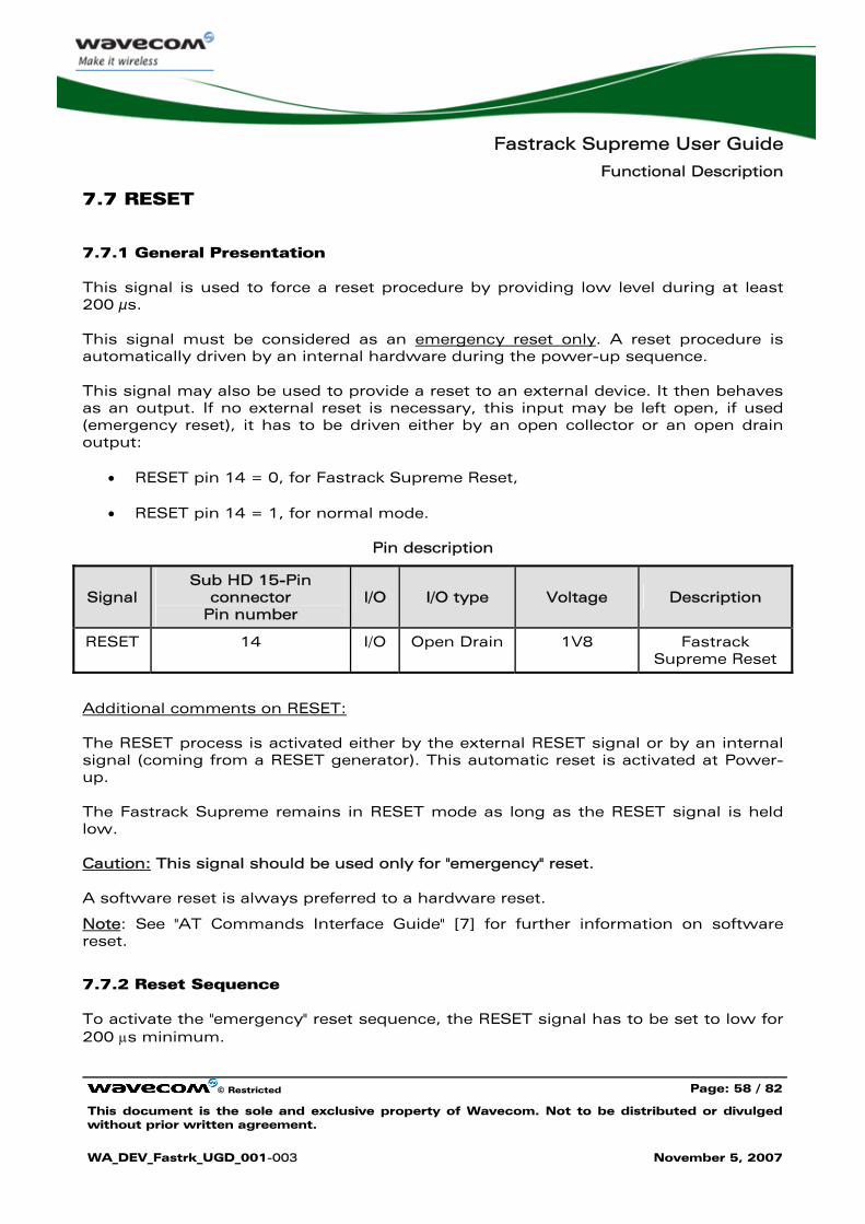
Fastrack Supreme User Guide
Functional Description
© Restricted Page: 58 / 82
This document is the sole and exclusive property of Wavecom. Not to be distributed or divulged without prior written agreement.
WA_DEV_Fastrk_UGD_001-003 November 5, 2007
7.7 RESET
7.7.1 General Presentation
This signal is used to force a reset procedure by providing low level during at least 200 μs.
This signal must be considered as an emergency reset only. A reset procedure is automatically driven by an internal hardware during the power-up sequence.
This signal may also be used to provide a reset to an external device. It then behaves as an output. If no external reset is necessary, this input may be left open, if used (emergency reset), it has to be driven either by an open collector or an open drain output:
• RESET pin 14 = 0, for Fastrack Supreme Reset,
• RESET pin 14 = 1, for normal mode.
Pin description
Signal Sub HD 15-Pin
connector Pin number
I/O I/O type Voltage Description
RESET 14 I/O Open Drain 1V8 Fastrack Supreme Reset
Additional comments on RESET:
The RESET process is activated either by the external RESET signal or by an internal signal (coming from a RESET generator). This automatic reset is activated at Power-up.
The Fastrack Supreme remains in RESET mode as long as the RESET signal is held low.
Caution: This signal should be used only for "emergency" reset.
A software reset is always preferred to a hardware reset.
Note: See "AT Commands Interface Guide" [7] for further information on software reset.
7.7.2 Reset Sequence
To activate the "emergency" reset sequence, the RESET signal has to be set to low for 200 μs minimum.
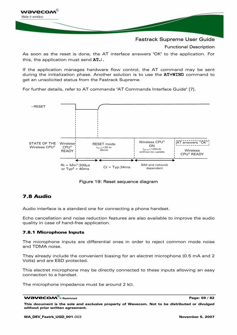
Fastrack Supreme User Guide
Functional Description
© Restricted Page: 59 / 82
This document is the sole and exclusive property of Wavecom. Not to be distributed or divulged without prior written agreement.
WA_DEV_Fastrk_UGD_001-003 November 5, 2007
As soon as the reset is done, the AT interface answers "OK" to the application. For this, the application must send AT↵.
If the application manages hardware flow control, the AT command may be sent during the initialization phase. Another solution is to use the AT+WIND command to get an unsolicited status from the Fastrack Supreme.
For further details, refer to AT commands "AT Commands Interface Guide" [7].
RESET mode IBB+RF=20 to
40mA
~RESET
STATE OF THE Wireless CPU®
Wireless CPU®
READY
Rt = Min1:200μs or Typ2 = 40ms
AT answers “OK”
Wireless CPU® READY
SIM and network dependent
Wireless CPU® ON
IBB+RF<120mA without loc update
Ct = Typ:34ms
Figure 19: Reset sequence diagram
7.8 Audio
Audio interface is a standard one for connecting a phone handset.
Echo cancellation and noise reduction features are also available to improve the audio quality in case of hand-free application.
7.8.1 Microphone Inputs
The microphone inputs are differential ones in order to reject common mode noise and TDMA noise.
They already include the convenient biasing for an electret microphone (0.5 mA and 2 Volts) and are ESD protected.
This electret microphone may be directly connected to these inputs allowing an easy connection to a handset.
The microphone impedance must be around 2 kΩ.
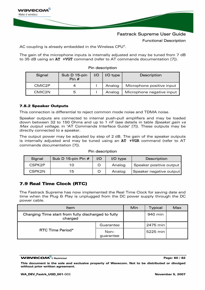
Fastrack Supreme User Guide
Functional Description
© Restricted Page: 60 / 82
This document is the sole and exclusive property of Wavecom. Not to be distributed or divulged without prior written agreement.
WA_DEV_Fastrk_UGD_001-003 November 5, 2007
AC coupling is already embedded in the Wireless CPU®.
The gain of the microphone inputs is internally adjusted and may be tuned from 7 dB to 35 dB using an AT +VGT command (refer to AT commands documentation [7]).
Pin description
Signal Sub D 15-pin Pin #
I/O I/O type Description
CMIC2P 4 I Analog Microphone positive input
CMIC2N 5 I Analog Microphone negative input
7.8.2 Speaker Outputs
This connection is differential to reject common mode noise and TDMA noise.
Speaker outputs are connected to internal push-pull amplifiers and may be loaded down between 32 to 150 Ohms and up to 1 nF (see details in table Speaker gain vs Max output voltage, in "AT Commands Interface Guide" [7]). These outputs may be directly connected to a speaker.
The output power may be adjusted by step of 2 dB. The gain of the speaker outputs is internally adjusted and may be tuned using an AT +VGR command (refer to AT commands documentation [7]).
Pin description
Signal Sub D 15-pin Pin # I/O I/O type Description
CSPK2P 10 O Analog Speaker positive output
CSPK2N 15 O Analog Speaker negative output
7.9 Real Time Clock (RTC)
The Fastrack Supreme has now implemented the Real Time Clock for saving date and time when the Plug & Play is unplugged from the DC power supply through the DC power cable.
Item Min Typical Max
Charging Time start from fully discharged to fully charged
940 min
Guarantee 2475 min
RTC Time Period* Non-guarantee
5225 min
Fastrack Supreme User Guide
Functional Description
© Restricted Page: 61 / 82
This document is the sole and exclusive property of Wavecom. Not to be distributed or divulged without prior written agreement.
WA_DEV_Fastrk_UGD_001-003 November 5, 2007
Remark:
1. This RTC time period is measured when the RTC battery is fully charged before the Fastrack Supreme is being unplugged from the DC power source.
2. This RTC time period is for temperature from -20°C to +60°C. Once the operating/storage temperature is beyond this range, this time period is not guaranteed.
Caution: When the Fastrack Supreme is shipped out, the charging voltage of the RTC battery is not guaranteed. Once the Fastrack Supreme is on power, the RTC battery will start charging and the RTC feature can then be resumed.
7.10 FLASH LED
The Fastrack Supreme has a red LED indicator to show the status of the GSM network. For detail description of the various status, please refer to Section 5.3.
However, during operation mode of Slow Standby, there will be no network registration and so the red LED indicator will always be ON. It is possible for user to deactivate the LED indication during Slow Standby mode, in order to reduce power consumption.
The Flash LED can be deactivated by AT command at+whcnf=1,0
The Flash LED can be activated by AT command at+whcnf=1,1
However, the new setting will be taken into account only after a restart. For detail, please refer to Document [7].
Fastrack Supreme User Guide
Technical Characteristics
© Restricted Page: 62 / 82
This document is the sole and exclusive property of Wavecom. Not to be distributed or divulged without prior written agreement.
WA_DEV_Fastrk_UGD_001-003 November 5, 2007
8 Technical Characteristics
8.1 Mechanical Characteristics
Table 15: Mechanical characteristics
Dimensions 73 x 54.5 x 25.5 mm (excluding connectors)
Overall Dimension 88 x 54.5 x 25.5 mm
Weight ≈ 89 grams (Fastrack Supreme only)
≈ 126 grams (Fastrack Supreme + bridles + power supply cable)
Volume 101.5 cm3
Housing Aluminum profiled
The next page gives the dimensioning diagram of the Fastrack Supreme including the clearance areas to take into account for the Fastrack Supreme installation.
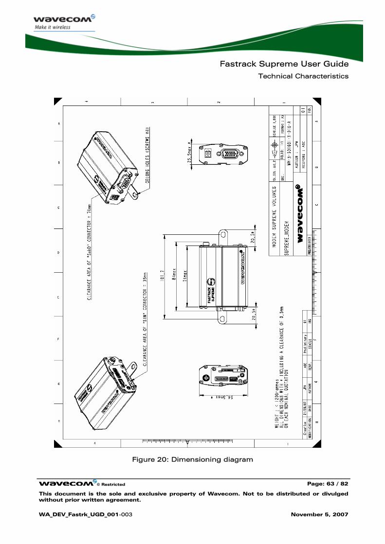
Fastrack Supreme User Guide
Technical Characteristics
© Restricted Page: 63 / 82
This document is the sole and exclusive property of Wavecom. Not to be distributed or divulged without prior written agreement.
WA_DEV_Fastrk_UGD_001-003 November 5, 2007
Figure 20: Dimensioning diagram
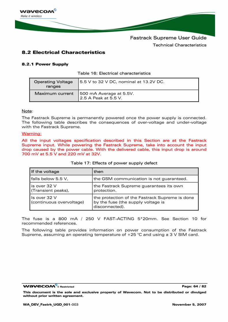
Fastrack Supreme User Guide
Technical Characteristics
© Restricted Page: 64 / 82
This document is the sole and exclusive property of Wavecom. Not to be distributed or divulged without prior written agreement.
WA_DEV_Fastrk_UGD_001-003 November 5, 2007
8.2 Electrical Characteristics
8.2.1 Power Supply
Table 16: Electrical characteristics
Operating Voltage ranges
5.5 V to 32 V DC, nominal at 13.2V DC.
Maximum current 500 mA Average at 5.5V. 2.5 A Peak at 5.5 V.
Note:
The Fastrack Supreme is permanently powered once the power supply is connected. The following table describes the consequences of over-voltage and under-voltage with the Fastrack Supreme.
Warning:
All the input voltages specification described in this Section are at the Fastrack Supreme input. While powering the Fastrack Supreme, take into account the input drop caused by the power cable. With the delivered cable, this input drop is around 700 mV at 5.5 V and 220 mV at 32V.
Table 17: Effects of power supply defect
If the voltage then
falls below 5.5 V, the GSM communication is not guaranteed.
is over 32 V (Transient peaks),
the Fastrack Supreme guarantees its own protection.
Is over 32 V (continuous overvoltage)
the protection of the Fastrack Supreme is done by the fuse (the supply voltage is disconnected).
The fuse is a 800 mA / 250 V FAST-ACTING 5*20mm. See Section 10 for recommended references.
The following table provides information on power consumption of the Fastrack Supreme, assuming an operating temperature of +25 °C and using a 3 V SIM card.
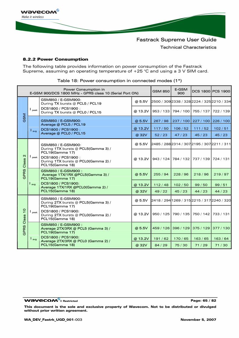
Fastrack Supreme User Guide
Technical Characteristics
© Restricted Page: 65 / 82
This document is the sole and exclusive property of Wavecom. Not to be distributed or divulged without prior written agreement.
WA_DEV_Fastrk_UGD_001-003 November 5, 2007
8.2.2 Power Consumption
The following table provides information on power consumption of the Fastrack Supreme, assuming an operating temperature of +25 °C and using a 3 V SIM card.
Table 18: Power consumption in connected modes (1*)
Power Consumption in E-GSM 900/DCS 1800 MHz - GPRS class 10 (Serial Port ON)
GSM 850 E-GSM 900
DCS 1800 PCS 1900
@ 5.5V 2500 / 309 2338 / 328 2224 / 325 2210 / 334
I peak
GSM850 / E-GSM900: During TX bursts @ PCL5 / PCL19
DCS1800 / PCS1900 : During TX bursts @ PCL0 / PCL15 @ 13.2V 953 / 133 794 / 100 755 / 137 722 / 139
@ 5.5V 267 / 98 237 / 100 227 / 100 226 / 100
@ 13.2V 117 / 50 106 / 52 111 / 52 102 / 51
GS
M
I avg
GSM850 / E-GSM900: Average @ PCL5 / PCL19
DCS1800 / PCS1900 : Average @ PCL0 / PCL15 @ 32V 52 / 23 47 / 23 45 / 23 45 / 23
@ 5.5V 2485 / 288 2314 / 307 2195 / 307 2211 / 311
I peak
GSM850 / E-GSM900: During 1TX bursts @ PCL5(Gamma 3) / PCL19(Gamma 17)
DCS1800 / PCS1900 : During 1TX bursts @ PCL0(Gamma 2) / PCL15(Gamma 18)
@ 13.2V 943 / 124 784 / 132 737 / 139 724 / 131
@ 5.5V 255 / 94 228 / 96 218 / 96 219 / 97
@ 13.2V 112 / 48 102 / 50 99 / 50 99 / 51
GP
RS
Cla
ss 2
I avg
GSM850 / E-GSM900 : Average 1TX/1RX @PCL5(Gamma 3) / PCL19(Gamma 17)
DCS1800 / PCS1900: Average 1TX/1RX @PCL0(Gamma 2) / PCL15(Gamma 18) @ 32V 49 / 22 45 / 23 44 / 23 44 / 23
@ 5.5V 2418 / 294 1269 / 315 2215 / 317 2240 / 320
I peak
GSM850 / E-GSM900: During 2TX bursts @ PCL5(Gamma 3) / PCL19(Gamma 17)
DCS1800 / PCS1900: During 2TX bursts @ PCL0(Gamma 2) / PCL15(Gamma 18)
@ 13.2V 950 / 125 790 / 135 750 / 142 733 / 131
@ 5.5V 459 / 126 396 / 129 375 / 129 377 / 130
@ 13.2V 191 / 62 170 / 65 163 / 65 163 / 64
GP
RS
Cla
ss 1
0
I avg
GSM850 / E-GSM900 : Average 2TX/3RX @ PCL5 (Gamma 3) / PCL19(Gamma 17)
DCS1800 / PCS1900: Average 2TX/3RX @ PCL0 (Gamma 2) / PCL15(Gamma 18) @ 32V 84 / 29 75 / 30 71 / 29 71 / 30
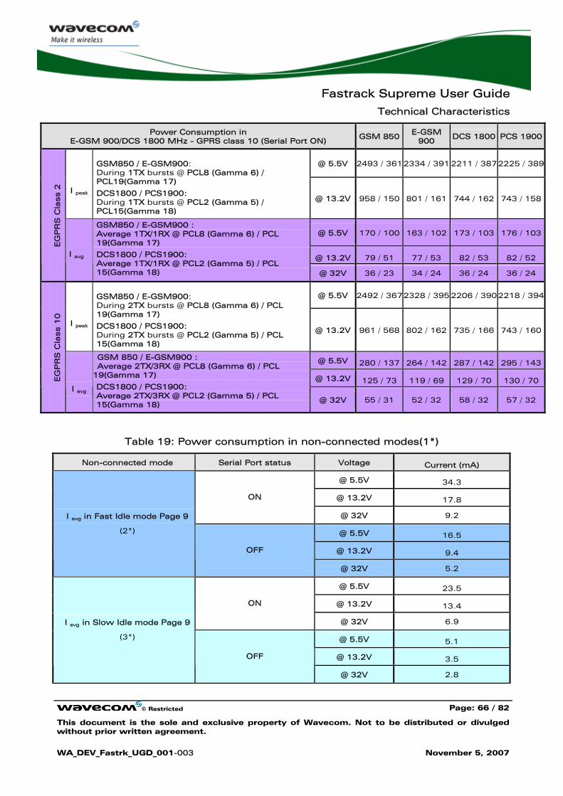
Fastrack Supreme User Guide
Technical Characteristics
© Restricted Page: 66 / 82
This document is the sole and exclusive property of Wavecom. Not to be distributed or divulged without prior written agreement.
WA_DEV_Fastrk_UGD_001-003 November 5, 2007
Power Consumption in E-GSM 900/DCS 1800 MHz - GPRS class 10 (Serial Port ON)
GSM 850 E-GSM 900
DCS 1800 PCS 1900
@ 5.5V 2493 / 361 2334 / 391 2211 / 387 2225 / 389
I peak
GSM850 / E-GSM900: During 1TX bursts @ PCL8 (Gamma 6) / PCL19(Gamma 17)
DCS1800 / PCS1900: During 1TX bursts @ PCL2 (Gamma 5) / PCL15(Gamma 18)
@ 13.2V 958 / 150 801 / 161 744 / 162 743 / 158
@ 5.5V 170 / 100 163 / 102 173 / 103 176 / 103
@ 13.2V 79 / 51 77 / 53 82 / 53 82 / 52
EG
PR
S C
lass 2
I avg
GSM850 / E-GSM900 : Average 1TX/1RX @ PCL8 (Gamma 6) / PCL 19(Gamma 17)
DCS1800 / PCS1900: Average 1TX/1RX @ PCL2 (Gamma 5) / PCL 15(Gamma 18) @ 32V 36 / 23 34 / 24 36 / 24 36 / 24
@ 5.5V 2492 / 367 2328 / 395 2206 / 390 2218 / 394
I peak
GSM850 / E-GSM900: During 2TX bursts @ PCL8 (Gamma 6) / PCL 19(Gamma 17)
DCS1800 / PCS1900: During 2TX bursts @ PCL2 (Gamma 5) / PCL 15(Gamma 18)
@ 13.2V 961 / 568 802 / 162 735 / 166 743 / 160
@ 5.5V 280 / 137 264 / 142 287 / 142 295 / 143
@ 13.2V 125 / 73 119 / 69 129 / 70 130 / 70 EG
PR
S C
lass 1
0
I avg
GSM 850 / E-GSM900 : Average 2TX/3RX @ PCL8 (Gamma 6) / PCL
19(Gamma 17)
DCS1800 / PCS1900: Average 2TX/3RX @ PCL2 (Gamma 5) / PCL 15(Gamma 18)
@ 32V 55 / 31 52 / 32 58 / 32 57 / 32
Table 19: Power consumption in non-connected modes(1*)
Non-connected mode Serial Port status Voltage Current (mA)
@ 5.5V 34.3
@ 13.2V 17.8 ON
@ 32V 9.2
@ 5.5V 16.5
@ 13.2V 9.4
I avg in Fast Idle mode Page 9
(2*)
OFF
@ 32V 5.2
@ 5.5V 23.5
@ 13.2V 13.4 ON
@ 32V 6.9
@ 5.5V 5.1
@ 13.2V 3.5
I avg in Slow Idle mode Page 9
(3*)
OFF
@ 32V 2.8

Fastrack Supreme User Guide
Technical Characteristics
© Restricted Page: 67 / 82
This document is the sole and exclusive property of Wavecom. Not to be distributed or divulged without prior written agreement.
WA_DEV_Fastrk_UGD_001-003 November 5, 2007
Non-connected mode Serial Port status Voltage Current (mA)
@ 5.5V 51.4
@ 13.2V 25.9 ON
@ 32V 13.2
@ 5.5V 33.9
@ 13.2V 18.0
I avg in Fast Standby mode
(4*)
OFF
@ 32V 9.3
@ 5.5V 24.2
@ 13.2V 13.8 ON
@ 32V 7.0
@ 5.5V 6.6
@ 13.2V 3.9
I avg in Slow Standby mode
(with FLASH LED activated)
(4*)
OFF
@ 32V 3.0
@ 5.5V 22.8
@ 13.2V 13.0 ON
@ 32V 6.7
@ 5.5V 4.1
@ 13.2V 3.1
I avg in Slow Standby mode
(with FLASH LED deactivated)
(4*)
OFF
@ 32V 2.7
(1*):The power consumption might vary by 5 % over the whole operating temperature range (-20 °C to +55 °C). (2*): In this Mode, the RF function is active and the Fastrack Supreme synchronized with the network, but there is no communication. (3*): In this Mode, the RF function is disabled, but regularly activated to keep the synchronization with the network. This Mode works only when the DTE send AT command to shut down the serial link by software approach (DTE turns DTR in inactive state). (4*): In this Mode, the RF function is disabled, and there is no synchronization with the network.
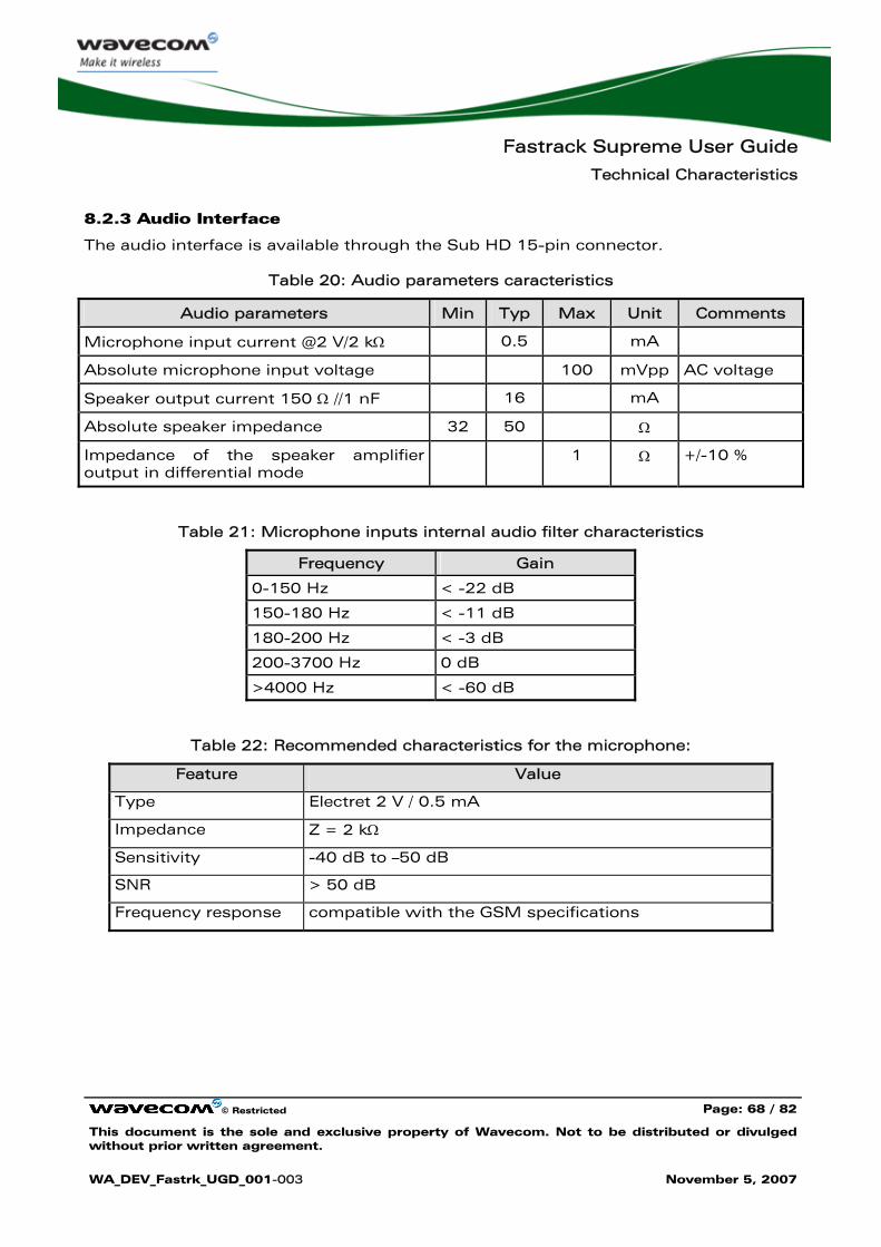
Fastrack Supreme User Guide
Technical Characteristics
© Restricted Page: 68 / 82
This document is the sole and exclusive property of Wavecom. Not to be distributed or divulged without prior written agreement.
WA_DEV_Fastrk_UGD_001-003 November 5, 2007
8.2.3 Audio Interface
The audio interface is available through the Sub HD 15-pin connector.
Table 20: Audio parameters caracteristics
Audio parameters Min Typ Max Unit Comments
Microphone input current @2 V/2 kΩ 0.5 mA
Absolute microphone input voltage 100 mVpp AC voltage
Speaker output current 150 Ω //1 nF 16 mA
Absolute speaker impedance 32 50 Ω
Impedance of the speaker amplifier output in differential mode
1 Ω +/-10 %
Table 21: Microphone inputs internal audio filter characteristics
Frequency Gain
0-150 Hz < -22 dB
150-180 Hz < -11 dB
180-200 Hz < -3 dB
200-3700 Hz 0 dB
>4000 Hz < -60 dB
Table 22: Recommended characteristics for the microphone:
Feature Value
Type Electret 2 V / 0.5 mA
Impedance Z = 2 kΩ
Sensitivity -40 dB to –50 dB
SNR > 50 dB
Frequency response compatible with the GSM specifications
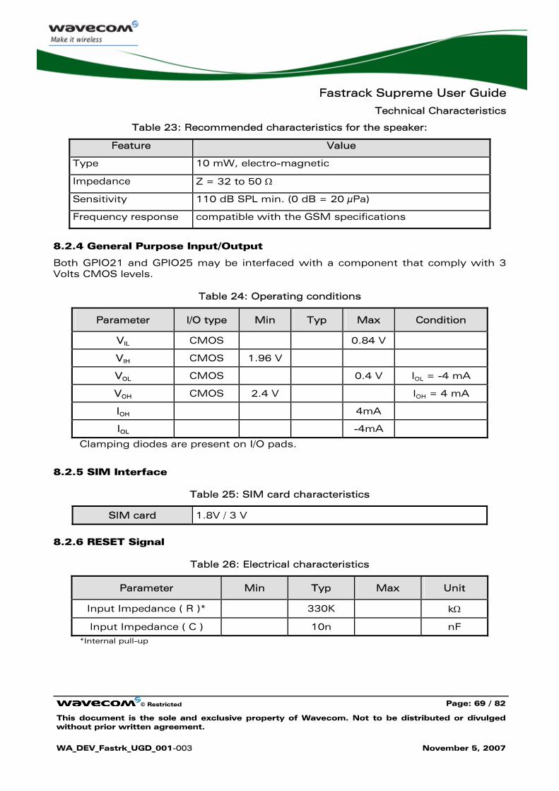
Fastrack Supreme User Guide
Technical Characteristics
© Restricted Page: 69 / 82
This document is the sole and exclusive property of Wavecom. Not to be distributed or divulged without prior written agreement.
WA_DEV_Fastrk_UGD_001-003 November 5, 2007
Table 23: Recommended characteristics for the speaker:
Feature Value
Type 10 mW, electro-magnetic
Impedance Z = 32 to 50 Ω
Sensitivity 110 dB SPL min. (0 dB = 20 μPa)
Frequency response compatible with the GSM specifications
8.2.4 General Purpose Input/Output
Both GPIO21 and GPIO25 may be interfaced with a component that comply with 3 Volts CMOS levels.
Table 24: Operating conditions
Parameter I/O type Min Typ Max Condition
VIL CMOS 0.84 V
VIH CMOS 1.96 V
VOL CMOS 0.4 V IOL = -4 mA
VOH CMOS 2.4 V IOH = 4 mA
IOH 4mA
IOL -4mA
Clamping diodes are present on I/O pads.
8.2.5 SIM Interface
Table 25: SIM card characteristics
SIM card 1.8V / 3 V
8.2.6 RESET Signal
Table 26: Electrical characteristics
Parameter Min Typ Max Unit
Input Impedance ( R )* 330K kΩ
Input Impedance ( C ) 10n nF *Internal pull-up
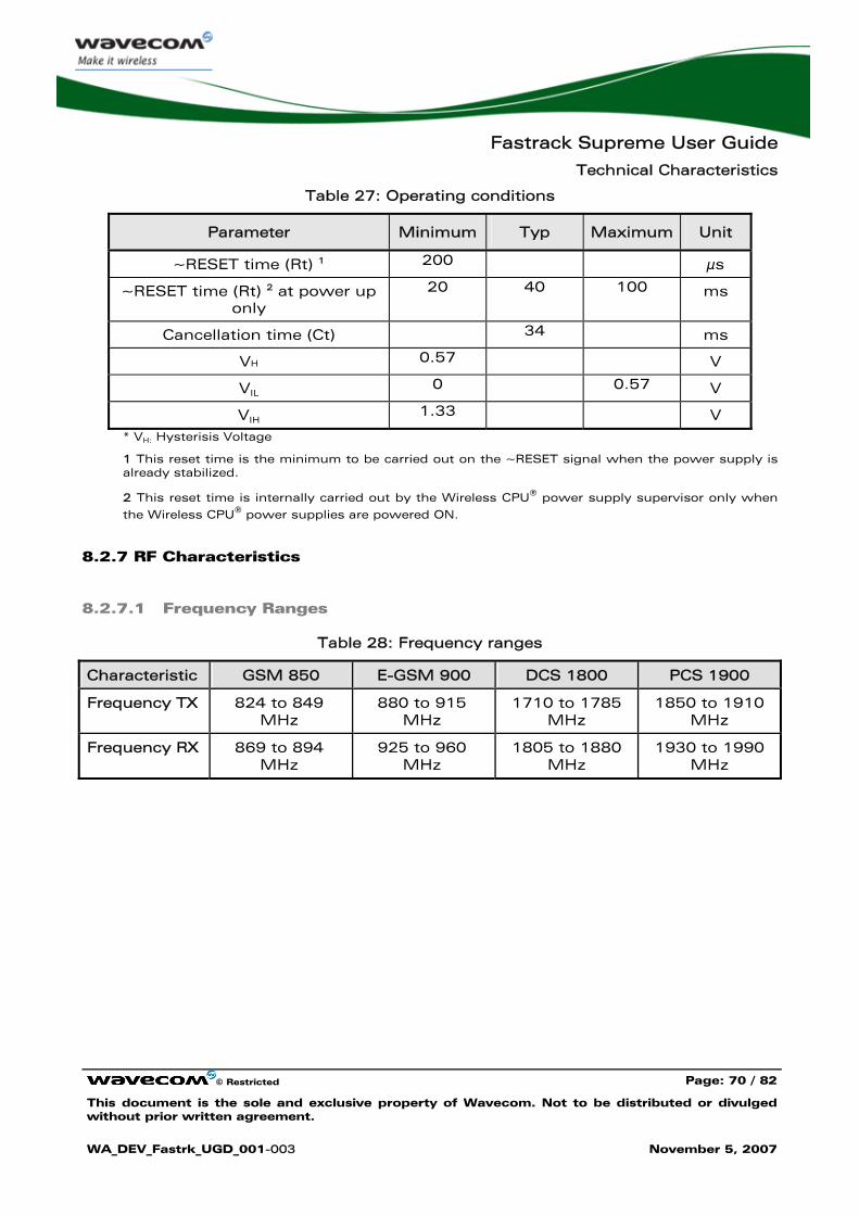
Fastrack Supreme User Guide
Technical Characteristics
© Restricted Page: 70 / 82
This document is the sole and exclusive property of Wavecom. Not to be distributed or divulged without prior written agreement.
WA_DEV_Fastrk_UGD_001-003 November 5, 2007
Table 27: Operating conditions
Parameter Minimum Typ Maximum Unit
~RESET time (Rt) 1 200 μs
~RESET time (Rt) 2 at power up only
20 40 100 ms
Cancellation time (Ct) 34 ms
VH 0.57 V
VIL 0 0.57 V
VIH 1.33 V * VH: Hysterisis Voltage
1 This reset time is the minimum to be carried out on the ~RESET signal when the power supply is already stabilized.
2 This reset time is internally carried out by the Wireless CPU® power supply supervisor only when
the Wireless CPU® power supplies are powered ON.
8.2.7 RF Characteristics
8.2.7.1 Frequency Ranges
Table 28: Frequency ranges
Characteristic GSM 850 E-GSM 900 DCS 1800 PCS 1900
Frequency TX 824 to 849 MHz
880 to 915 MHz
1710 to 1785 MHz
1850 to 1910 MHz
Frequency RX 869 to 894 MHz
925 to 960 MHz
1805 to 1880 MHz
1930 to 1990 MHz
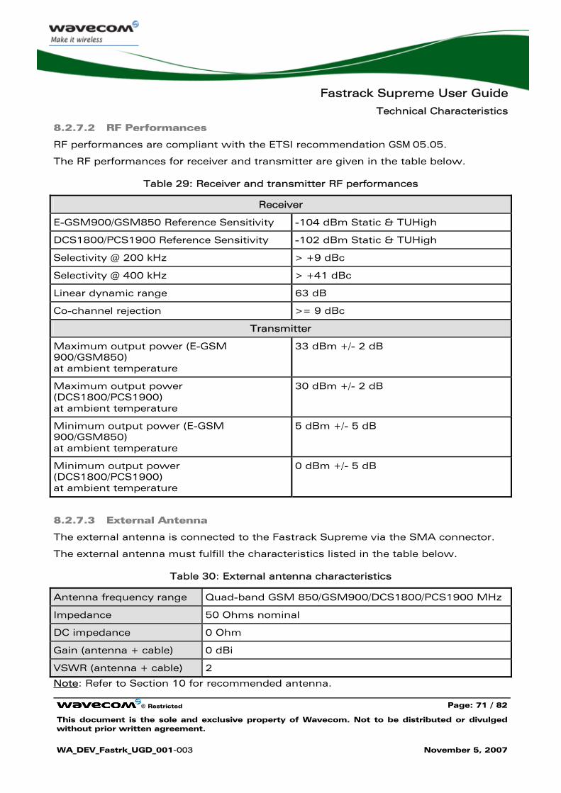
Fastrack Supreme User Guide
Technical Characteristics
© Restricted Page: 71 / 82
This document is the sole and exclusive property of Wavecom. Not to be distributed or divulged without prior written agreement.
WA_DEV_Fastrk_UGD_001-003 November 5, 2007
8.2.7.2 RF Performances
RF performances are compliant with the ETSI recommendation GSM 05.05.
The RF performances for receiver and transmitter are given in the table below.
Table 29: Receiver and transmitter RF performances
Receiver
E-GSM900/GSM850 Reference Sensitivity -104 dBm Static & TUHigh
DCS1800/PCS1900 Reference Sensitivity -102 dBm Static & TUHigh
Selectivity @ 200 kHz > +9 dBc
Selectivity @ 400 kHz > +41 dBc
Linear dynamic range 63 dB
Co-channel rejection >= 9 dBc
Transmitter
Maximum output power (E-GSM 900/GSM850) at ambient temperature
33 dBm +/- 2 dB
Maximum output power (DCS1800/PCS1900) at ambient temperature
30 dBm +/- 2 dB
Minimum output power (E-GSM 900/GSM850) at ambient temperature
5 dBm +/- 5 dB
Minimum output power (DCS1800/PCS1900) at ambient temperature
0 dBm +/- 5 dB
8.2.7.3 External Antenna
The external antenna is connected to the Fastrack Supreme via the SMA connector.
The external antenna must fulfill the characteristics listed in the table below.
Table 30: External antenna characteristics
Antenna frequency range Quad-band GSM 850/GSM900/DCS1800/PCS1900 MHz
Impedance 50 Ohms nominal
DC impedance 0 Ohm
Gain (antenna + cable) 0 dBi
VSWR (antenna + cable) 2
Note: Refer to Section 10 for recommended antenna.
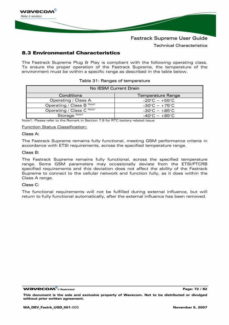
Fastrack Supreme User Guide
Technical Characteristics
© Restricted Page: 72 / 82
This document is the sole and exclusive property of Wavecom. Not to be distributed or divulged without prior written agreement.
WA_DEV_Fastrk_UGD_001-003 November 5, 2007
8.3 Environmental Characteristics
The Fastrack Supreme Plug & Play is compliant with the following operating class. To ensure the proper operation of the Fastrack Supreme, the temperature of the environment must be within a specific range as described in the table below.
Table 31: Ranges of temperature
No IESM Current Drain
Conditions Temperature Range Operating / Class A -20°C ~ +55°C
Operating / Class B Note1 -30°C ~ +75°C Operating / Class C Note1 -30°C ~ +85°C
Storage Note1 -40°C ~ +85°C Note1: Please refer to the Remark in Section 7.9 for RTC battery related issue.
Function Status Classification:
Class A:
The Fastrack Supreme remains fully functional, meeting GSM performance criteria in accordance with ETSI requirements, across the specified temperature range.
Class B:
The Fastrack Supreme remains fully functional, across the specified temperature range. Some GSM parameters may occasionally deviate from the ETSI/PTCRB specified requirements and this deviation does not affect the ability of the Fastrack Supreme to connect to the cellular network and function fully, as it does within the Class A range.
Class C:
The functional requirements will not be fulfilled during external influence, but will return to fully functional automatically, after the external influence has been removed.
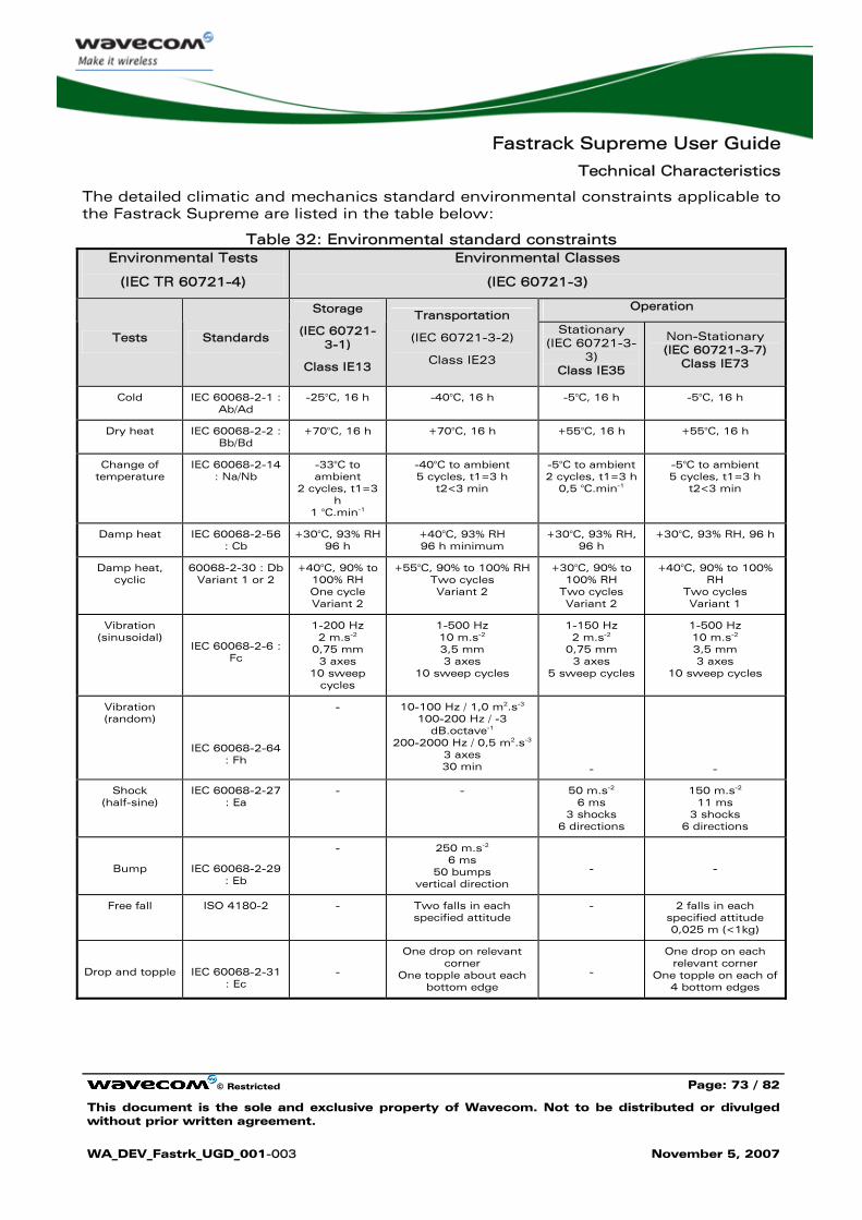
Fastrack Supreme User Guide
Technical Characteristics
© Restricted Page: 73 / 82
This document is the sole and exclusive property of Wavecom. Not to be distributed or divulged without prior written agreement.
WA_DEV_Fastrk_UGD_001-003 November 5, 2007
The detailed climatic and mechanics standard environmental constraints applicable to the Fastrack Supreme are listed in the table below:
Table 32: Environmental standard constraints Environmental Tests
(IEC TR 60721-4)
Environmental Classes
(IEC 60721-3)
Operation
Tests Standards
Storage
(IEC 60721-3-1)
Class IE13
Transportation
(IEC 60721-3-2)
Class IE23
Stationary (IEC 60721-3-
3) Class IE35
Non-Stationary (IEC 60721-3-7)
Class IE73
Cold IEC 60068-2-1 : Ab/Ad
-25°C, 16 h -40°C, 16 h -5°C, 16 h -5°C, 16 h
Dry heat IEC 60068-2-2 : Bb/Bd
+70°C, 16 h +70°C, 16 h +55°C, 16 h +55°C, 16 h
Change of temperature
IEC 60068-2-14 : Na/Nb
-33°C to ambient
2 cycles, t1=3 h
1 °C.min-1
-40°C to ambient 5 cycles, t1=3 h
t2<3 min
-5°C to ambient 2 cycles, t1=3 h
0,5 °C.min-1
-5°C to ambient 5 cycles, t1=3 h
t2<3 min
Damp heat IEC 60068-2-56 : Cb
+30°C, 93% RH 96 h
+40°C, 93% RH 96 h minimum
+30°C, 93% RH, 96 h
+30°C, 93% RH, 96 h
Damp heat, cyclic
60068-2-30 : Db Variant 1 or 2
+40°C, 90% to 100% RH One cycle Variant 2
+55°C, 90% to 100% RH Two cycles Variant 2
+30°C, 90% to 100% RH
Two cycles Variant 2
+40°C, 90% to 100% RH
Two cycles Variant 1
Vibration (sinusoidal)
IEC 60068-2-6 : Fc
1-200 Hz 2 m.s-2
0,75 mm 3 axes
10 sweep cycles
1-500 Hz 10 m.s-2
3,5 mm 3 axes
10 sweep cycles
1-150 Hz 2 m.s-2
0,75 mm 3 axes
5 sweep cycles
1-500 Hz 10 m.s-2
3,5 mm 3 axes
10 sweep cycles
Vibration (random)
IEC 60068-2-64 : Fh
- 10-100 Hz / 1,0 m2.s-3
100-200 Hz / -3 dB.octave-1
200-2000 Hz / 0,5 m2.s-3
3 axes 30 min
-
-
Shock (half-sine)
IEC 60068-2-27 : Ea
- - 50 m.s-2
6 ms 3 shocks
6 directions
150 m.s-2
11 ms 3 shocks
6 directions
Bump
IEC 60068-2-29 : Eb
- 250 m.s-2
6 ms 50 bumps
vertical direction
-
-
Free fall ISO 4180-2 - Two falls in each specified attitude
- 2 falls in each specified attitude 0,025 m (<1kg)
Drop and topple
IEC 60068-2-31 : Ec
-
One drop on relevant corner
One topple about each bottom edge
-
One drop on each relevant corner
One topple on each of 4 bottom edges
Fastrack Supreme User Guide
Technical Characteristics
© Restricted Page: 74 / 82
This document is the sole and exclusive property of Wavecom. Not to be distributed or divulged without prior written agreement.
WA_DEV_Fastrk_UGD_001-003 November 5, 2007
Notes:
Short description of Class IE13 (For more information see standard IEC 60721-3-1)
"Locations without controlled temperature and humidity, where heating may be used to raise low temperatures, locations in buildings providing minimal protection against daily variations of external climate, prone to receiving rainfall from carrying wind".
Short description of Class IE23 (For more information, see standard IEC 60721-3-2)
"Transportation in unventilated compartments and in conditions without protection against bad weather, in all sorts of trucks and trailers in areas of well developed road network, in trains equipped with buffers specially designed to reduce shocks and by boat".
Short description of Class IE35 (For more information see standard IEC 60721-3-3)
"Locations with no control on heat or humidity where heating may be used to raise low temperatures, to places inside a building to avoid extremely high temperatures, to places such as hallways, building staircases, cellars, certain workshops, equipment stations without surveillance".
Short description of Class IE73 (For more information see standard IEC 60721-3-7)
"Transfer to places where neither temperature nor humidity are controlled but where heating may be used to raise low temperatures, to places exposed to water droplets, products can be subjected to ice formation, these conditions are found in hallways and building staircases, garages, certain workshops, factory building and places for industrial processes and hardware stations without surveillance".
Warning: The specification in the above table applies to the Fastrack Supreme product only. Customers are advised to verify that the environmental specification of the SIM Card used is compliant with the Fastrack Supreme environmental specifications. Any application must be qualified by the customer with the SIM Card in storage, transportation and operation.
The use of standard SIM cards may drastically reduce the environmental conditions in which the Product can be used. These cards are particularly sensible to humidity and temperature changes. These conditions may produce oxidation of the SIM card metallic layers and cause, in the long term, electrical discontinuities. This is particularly true in left alone applications, where no frequent extraction/insertion of the SIM card is performed.
In case of mobility when the application is moved through different environments with temperature variations, some condensation may appear. These events have a negative impact on the SIM and may favor oxidation.
If the use of standard SIM card, with exposition to the environmental conditions described above, can not be avoided, special care must be taken in the integration of the final application in order to minimize the impact of these conditions. The solutions that may be proposed are:
• Lubrication of the SIM card to protect the SIM Contact from oxidation. • Putting the Fastrack Supreme Plug & Play in a waterproof enclosure with
desiccant bags.
Fastrack Supreme User Guide
Technical Characteristics
© Restricted Page: 75 / 82
This document is the sole and exclusive property of Wavecom. Not to be distributed or divulged without prior written agreement.
WA_DEV_Fastrk_UGD_001-003 November 5, 2007
Lubrication of the SIM card had been tested by Wavecom (using Tutela Fluid 43EM from MOLYDUVAL) and gives very good results.
If waterproof enclosure with a desiccant solution is used, check with your desiccant retailer the quantity that must be used according to the enclosure dimensions. Ensure humidity has been removed before sealing the enclosure.
Any solution selected must be qualified by the customer on the final application.
To minimize oxidation problem on the SIM card, its manipulation must be done with the greatest precautions. In particular, the metallic contacts of the card must never be touched with bare fingers or any matter which may contain polluted materials liable to produce oxidation (such as, e.g. substances including chlorine). In case a cleaning of the Card is necessary, a dry cloth must be used (never use any chemical substance).
8.4 Conformity
The complete product complies with the essential requirements of article 3 of R&TTE 1999/5/EC Directive and satisfied the following standards:
Domain Applicable standard
Safety standard EN 60950 (ed.1999)
Efficient use of the radio frequency spectrum
EN 301 419-(v 4.1.1)
EN 301 511 (V 9.0.2)
EMC EN 301 489–1 (edition 2002)
EN 301 489-7 (edition 2002)
Global Certification Forum – Certification Criteria
GCF-CC V3.26.0
PTCRB NAPRD.03 V3.11.0
FCC FCC Part 15 FCC Part 22, 24
IC RSS-132 Issue 2 RSS-133 Issue 3
8.5 Protections
8.5.1 Power Supply
The Fastrack Supreme is protected by a 800 mA / 250 V fuse directly bonded on the power supply cable.
The model of fuse used is: FSD 800 mA / 250 V FAST-ACTING.
Fastrack Supreme User Guide
Technical Characteristics
© Restricted Page: 76 / 82
This document is the sole and exclusive property of Wavecom. Not to be distributed or divulged without prior written agreement.
WA_DEV_Fastrk_UGD_001-003 November 5, 2007
8.5.2 Overvoltage
The Fastrack Supreme is protected against voltage over +32 V.
When input voltages exceed +32 V, the supply voltage is disconnected in order to protect the internal electronic components from an overvoltage.
8.5.3 Electrostatic Discharge
The Fastrack Supreme withstands ESD according to IEC 1000-4-2 requirements for all accessible parts of the Fastrack Supreme except the RF part:
• 8 kV of air discharge,
• 4 kV of contact discharge.
8.5.4 Miscellaneous
Filtering guarantees:
• EMI/RFI protection in input and output,
• Signal smoothing.
Fastrack Supreme User Guide
Safety Recommendations
© Restricted Page: 77 / 82
This document is the sole and exclusive property of Wavecom. Not to be distributed or divulged without prior written agreement.
WA_DEV_Fastrk_UGD_001-003 November 5, 2007
9 Safety Recommendations
9.1 General Safety
It is important to follow any special regulations regarding the use of radio equipment due in particular to the possibility of radio frequency (RF) interference. Please follow the safety advice given below carefully.
Switch OFF your Wireless CPU®:
• When in an aircraft. The use of cellular telephones in an aircraft may endanger the operation of the aircraft, disrupt the cellular network and is illegal. Failure to observe this instruction may lead to suspension or denial of cellular telephone services to the offender, or legal action or both,
• When at a refueling point,
• When in any area with a potentially explosive atmosphere which could cause an explosion or fire,
• In hospitals and any other place where medical equipment may be in use.
Respect restrictions on the use of radio equipment in:
• Fuel depots,
• Chemical plants,
• Places where blasting operations are in progress,
• Any other area where signalization reminds that the use of cellular telephone is forbidden or dangerous.
• Any other area where you would normally be advised to turn off your vehicle engine.
There may be a hazard associated with the operation of your Fastrack Supreme Plug & Play close to inadequately protected personal medical devices such as hearing aids and pacemakers. Consult the manufacturers of the medical device to determine if it is adequately protected.
Operation of your Fastrack Supreme Plug & Play close to other electronic equipment may also cause interference if the equipment is inadequately protected. Observe any warning signs and manufacturers’ recommendations.
The Fastrack Supreme Plug & Play is designed for and intended to be used in "fixed" and "mobile" applications:
"Fixed" means that the device is physically secured at one location and is not able to be easily moved to another location.
"Mobile" means that the device is designed to be used in other than fixed locations and generally in such a way that a separation distance of at least 20 cm (8 inches) is normally maintained between the transmitter’s antenna and the body of the user or nearby persons.
Fastrack Supreme User Guide
Safety Recommendations
© Restricted Page: 78 / 82
This document is the sole and exclusive property of Wavecom. Not to be distributed or divulged without prior written agreement.
WA_DEV_Fastrk_UGD_001-003 November 5, 2007
The Fastrack Supreme Plug & Play is not designed for and intended to be used in portable applications (within 20 cm or 8 inches of the body of the user) and such uses are strictly prohibited.
9.2 Vehicle Safety
Do not use your Fastrack Supreme Plug & Play while driving, unless equipped with a correctly installed vehicle kit allowing ’Hands-Free’ Operation.
Respect national regulations on the use of cellular telephones in vehicles. Road safety always comes first.
If incorrectly installed in a vehicle, the operation of Fastrack Supreme Plug & Play telephone could interfere with the correct functioning of vehicle electronics. To avoid such problems, make sure that the installation has been performed by a qualified personnel. Verification of the protection of vehicle electronics should form part of the installation.
The use of an alert device to operate a vehicle’s lights or horn on public roads is not permitted.
9.3 Care and Maintenance
Your Fastrack Supreme Plug & Play is the product of advanced engineering, design and craftsmanship and should be treated with care. The suggestion below will help you to enjoy this product for many years.
Do not expose the Fastrack Supreme Plug & Play to any extreme environment where the temperature or humidity is high.
Do not use or store the Fastrack Supreme Plug & Play in dusty or dirty areas. Its moving parts (SIM holder for example) can be damaged.
Do not attempt to disassemble the Wireless CPU®. There are no user serviceable parts inside.
Do not expose the Fastrack Supreme Plug & Play to water, rain or spilt beverages. It is not waterproof.
Do not abuse your Fastrack Supreme Plug & Play by dropping, knocking, or violently shaking it. Rough handling can damage it.
Do not place the Fastrack Supreme Plug & Play alongside computer discs, credit or travel cards or other magnetic media. The information contained on discs or cards may be affected by the Wireless CPU®.
The use of third party equipment or accessories, not made or authorized by Wavecom may invalidate the warranty of the Wireless CPU®.
Do contact an authorized Service Center in the unlikely event of a fault in the Wireless CPU®.
Fastrack Supreme User Guide
Safety Recommendations
© Restricted Page: 79 / 82
This document is the sole and exclusive property of Wavecom. Not to be distributed or divulged without prior written agreement.
WA_DEV_Fastrk_UGD_001-003 November 5, 2007
9.4 Your Responsibility
This Fastrack Supreme Plug & Play is under your responsibility. Please treat it with care respecting all local regulations. It is not a toy. Therefore, keep it in a safe place at all times and out of the reach of children.
Try to remember your Unlock and PIN codes. Become familiar with and use the security features to block unauthorized use and theft.
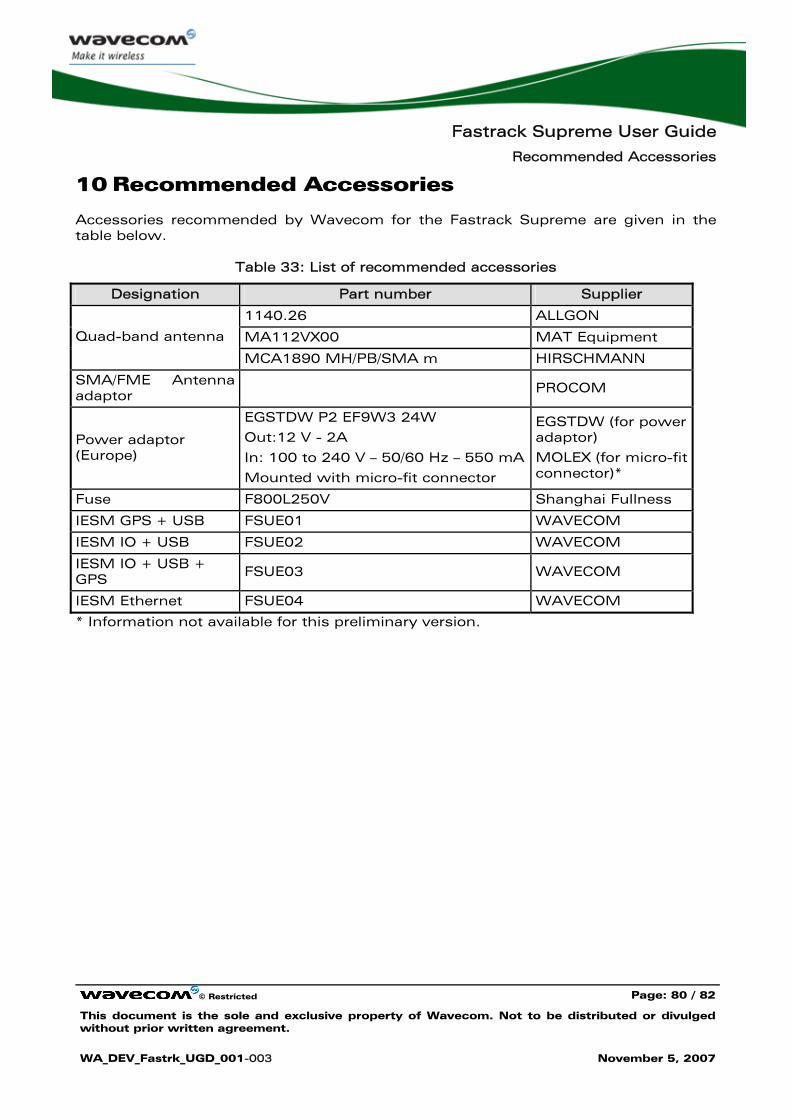
Fastrack Supreme User Guide
Recommended Accessories
© Restricted Page: 80 / 82
This document is the sole and exclusive property of Wavecom. Not to be distributed or divulged without prior written agreement.
WA_DEV_Fastrk_UGD_001-003 November 5, 2007
10 Recommended Accessories
Accessories recommended by Wavecom for the Fastrack Supreme are given in the table below.
Table 33: List of recommended accessories
Designation Part number Supplier
1140.26 ALLGON
MA112VX00 MAT Equipment Quad-band antenna
MCA1890 MH/PB/SMA m HIRSCHMANN
SMA/FME Antenna adaptor
PROCOM
Power adaptor (Europe)
EGSTDW P2 EF9W3 24W
Out:12 V - 2A
In: 100 to 240 V – 50/60 Hz – 550 mA
Mounted with micro-fit connector
EGSTDW (for power adaptor)
MOLEX (for micro-fit connector)*
Fuse F800L250V Shanghai Fullness
IESM GPS + USB FSUE01 WAVECOM
IESM IO + USB FSUE02 WAVECOM
IESM IO + USB + GPS
FSUE03 WAVECOM
IESM Ethernet FSUE04 WAVECOM
* Information not available for this preliminary version.
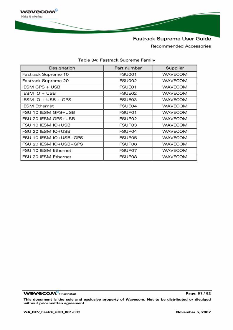
Fastrack Supreme User Guide
Recommended Accessories
© Restricted Page: 81 / 82
This document is the sole and exclusive property of Wavecom. Not to be distributed or divulged without prior written agreement.
WA_DEV_Fastrk_UGD_001-003 November 5, 2007
Table 34: Fastrack Supreme Family
Designation Part number Supplier
Fastrack Supreme 10 FSU001 WAVECOM
Fastrack Supreme 20 FSU002 WAVECOM
IESM GPS + USB FSUE01 WAVECOM
IESM IO + USB FSUE02 WAVECOM
IESM IO + USB + GPS FSUE03 WAVECOM
IESM Ethernet FSUE04 WAVECOM
FSU 10 IESM GPS+USB FSUP01 WAVECOM
FSU 20 IESM GPS+USB FSUP02 WAVECOM
FSU 10 IESM IO+USB FSUP03 WAVECOM
FSU 20 IESM IO+USB FSUP04 WAVECOM
FSU 10 IESM IO+USB+GPS FSUP05 WAVECOM
FSU 20 IESM IO+USB+GPS FSUP06 WAVECOM
FSU 10 IESM Ethernet FSUP07 WAVECOM
FSU 20 IESM Ethernet FSUP08 WAVECOM
Fastrack Supreme User Guide
Online Support
© Restricted Page: 82 / 82
This document is the sole and exclusive property of Wavecom. Not to be distributed or divulged without prior written agreement.
WA_DEV_Fastrk_UGD_001-003 November 5, 2007
11 Online Support
Wavecom provides an extensive range on online support which includes the following areas of Wavecom’s wireless expertise:
• the latest version of this document
• new versions of our Operating System user guides
• comprehensive support for Open AT®
• regulatory certifications
• carrier certifications
• application notes
To gain access to this support, simply visit our web site at http://www.wavecom.com/fastracksupreme or click on the desire link in Page. Privileged access via user login is provided to Wavecom authorized distributors.

WAVECOM S.A. - 3 esplanade du Foncet - 92442 Issy-les-Moulineaux Cedex - France - Tel: +33(0)1 46 29 08 00 - Fax: +33(0)1 46 29 08 08Wavecom, Inc. - 4810 Eastgate Mall - Second Floor - San Diego, CA 92121 - USA - Tel: +1 858 362 0101 - Fax: +1 858 558 5485WAVECOM Asia Pacific Ltd. - Unit 201-207, 2nd Floor, Bio-Informatics Centre – No.2 Science Park West Avenue - Hong Kong Science Park, Shatin
- New Territories, Hong Kong