fastrack plotter
TRANSCRIPT

FasTrackTM
Cutter
Owner's Guide

COPYRIGHT NOTICECOPYRIGHT 1999 Gerber Scientific Products, Inc. All Rights Reserved.
This document may not be reproduced by any means, in whole or in part, without written permission of thecopyright owner.
This document is furnished to support the FasTrack™ Cutter. In consideration of the furnishing of theinformation contained in this document, the party to whom it is given assumes its custody and control andagrees to the following:
1. The information herein contained is given in confidence, and any part thereof shall not be copied orreproduced without written consent of Gerber Scientific Products, Inc.
2. This document or the contents herein under no circumstances shall be used in the manufacture orreproduction of the article shown and the delivery of this document shall not constitute any right orlicense to do so.
Information contained in this document is subject to change without notice.
Printed in USA
GRAPHIX ADVANTAGE and GSP are registered trademarks and FasTrack is a trademark of GerberScientific Products, Inc. HPGL is a trademark of Hewlett-Packard Company. Windows is a registeredtrademark of Microsoft Corporation in the U.S. and other countries. MS-DOS and Microsoft are registeredtrademarks of Microsoft Corporation. HPGL is a trademark of Hewlett-Packard Company.

FCC WARNINGThis equipment has been tested and found to comply with the limits for a Class A digital device, pursuant toPart 15 of the FCC rules. These limits are designed to provide reasonable protection against harmfulinterference when the equipment is operated in a commercial environment. This equipment generates, uses,and can radiate radio frequency energy and, if not installed and used in accordance with the instructionmanual, may cause harmful interference to radio communications. Operation of this equipment in aresidential area is likely to cause harmful interference in which case the user will be required to correct theinterference at his own risk.
This digital apparatus does not exceed the Class B limits for radio noise emissions from digital apparatus setout in the Radio Interference Regulations of the Canadian Department of Communications.
Le present appareil numerique n'emet pas de bruits radioelectriques depassant les limites applicables auxappareils numeriques de la classe B prescrites dans les Reglements sur le brouillage radioelectrique edicte parle Ministere des Communications du Canada.

TABLE OF CONTENTSINTRODUCTION............................................................................................................. 1
ATTENTIONS AND CAUTIONS ............................................................................................................ 1CUSTOMER SUPPORT ........................................................................................................................ 2
CHAPTER 1 INSTALLATION PROCEDURES .............................................................. 4
PREPARING THE CUTTER ENVIRONMENT....................................................................................... 4UNPACKING AND SETTING UP THE CUTTER................................................................................... 5
Cutter box contents.......................................................................................................................... 6CUTTER PARTS and COMPONENTS.................................................................................................. 7CONTROL PANEL ................................................................................................................................. 9CONNECTING THE CUTTER TO THE COMPUTER ......................................................................... 10
Serial interface............................................................................................................................... 10To connect the serial interface....................................................................................................... 10
CONNECTING THE POWER CABLE ................................................................................................. 11INSTALLING KNIFE HOLDERS OR PENS......................................................................................... 12LOADING MATERIAL .......................................................................................................................... 13
To load cut-sheet material ............................................................................................................. 13To load roll material ....................................................................................................................... 15To straighten the material edge using the auto-sheet-off utility..................................................... 17
CHAPTER 2 CUTTER CONTROLS ............................................................................. 18
UNDERSTANDING THE CONTROL PANEL ...................................................................................... 18Online and Offline modes .............................................................................................................. 18Slew keys....................................................................................................................................... 19ORIGIN key.................................................................................................................................... 19PAGE key ...................................................................................................................................... 20ENTER key .................................................................................................................................... 20Menu keys...................................................................................................................................... 21VALUE keys................................................................................................................................... 21
GENERAL PROCEDURE TO CHANGE SETTINGS ON THE CUTTER ............................................ 22TOOL SELECTION .............................................................................................................................. 23TOOLKIND SELECTION...................................................................................................................... 24
To change the TOOLKIND ............................................................................................................ 24FORCE SELECTION ........................................................................................................................... 25
First Range (15 - 100 grams)......................................................................................................... 26Second Range (110 - 190 grams) ................................................................................................. 26Third Range (200 - 500 grams) ..................................................................................................... 26
SPEED SELECTION............................................................................................................................ 27ACCELERATION SELECTION............................................................................................................ 27PAGE LENGTH.................................................................................................................................... 27
To set the PAGE LENGTH ............................................................................................................ 28RESET and CLEAR FUNCTION.......................................................................................................... 29AVAILABLE VALUES/SETTINGS FOR PARAMETERS - IMPERIAL SYSTEM................................. 30AVAILABLE VALUES/SETTINGS FOR PARAMETERS, METRIC SYSTEM ..................................... 31
CHAPTER 3 CUTTER SETTINGS and SPECIAL FUNCTIONS.................................. 32
INTRODUCTION.................................................................................................................................. 32CHANGING THE USER LANGUAGE.................................................................................................. 32MENU MODE OPERATION................................................................................................................. 32
To plot a complete setup sheet...................................................................................................... 33To plot a single line and change settings ...................................................................................... 33
Example of a FasTrack Cutter Setup Sheet .................................................................................. 34GENERAL SETTINGS ......................................................................................................................... 35TOOLKIND SELECTION...................................................................................................................... 35
To select a TOOLKIND.................................................................................................................. 35SHEET-OFF / PAGE MODE ................................................................................................................ 36
Page commands............................................................................................................................ 36To set the SHEET-OFF / PAGE MODE......................................................................................... 37
REPLOT FACTOR ............................................................................................................................... 38To set the replot factor................................................................................................................... 38
SMOOTHING ....................................................................................................................................... 39To change the smoothing settings................................................................................................. 39
COMMUNICATION SETTINGS ........................................................................................................... 40To change the serial communication settings ............................................................................... 41
LANGUAGE SETTINGS ...................................................................................................................... 42To change language settings......................................................................................................... 43
RESET TO FACTORY DEFAULTS ..................................................................................................... 43
CHAPTER 4 FINE TUNING THE CUTTER .................................................................. 44
ADJUSTING THE KNIFE DEPTH........................................................................................................ 45To adjust the knife depth of the standard tool holder .................................................................... 45To adjust the knife depth of the optional knife holder .................................................................... 47
FEATURES OF THE OPTIONAL KNIFEHOLDER.............................................................................. 48SETTING THE CUTTING PRESSURE / TEST SQUARES................................................................. 49SETTING THE OFFSET ...................................................................................................................... 49ADJUSTING THE OFFSET.................................................................................................................. 50SETTING UP FOR POUNCING (PUNCHING) APPLICATIONS......................................................... 52
Method 1. Pen-Up / Pen-Down sent by cutting software............................................................... 52Method 2. Use the incorporated pouncing (punching) capability of the cutter .............................. 52To adjust the pouncing tool............................................................................................................ 53
PERFORMING A TEST CUT............................................................................................................... 54GENERATING A PARAMETER SETTINGS PLOT ............................................................................. 55
CHAPTER 5 CUTTER MAINTENANCE and TROUBLESHOOTING .......................... 56
CLEANING and DAILY MAINTENANCE ............................................................................................. 56To clean the pressure rollers and drive rollers .............................................................................. 56To remove material particles from the cutter blade in a standard knife holder ............................. 57To remove material particles from the cutter blade in an optional knife holder with vernier ......... 57To clean the cutter ......................................................................................................................... 58
PARTS REPLACEMENT ..................................................................................................................... 58To replace the cutting mat ............................................................................................................. 58To replace the knife blade in the standard knife holder................................................................. 59To replace the knife blade in the optional knife holder with vernier............................................... 60To replace the auto-sheet-off knife................................................................................................ 61
TROUBLESHOOTING ......................................................................................................................... 62To check the communication settings............................................................................................ 63
ERROR MESSAGES ........................................................................................................................... 65Unrecoverable system errors......................................................................................................... 65Recoverable system errors............................................................................................................ 68Communication errors ................................................................................................................... 69Language errors............................................................................................................................. 71
CHAPTER 6 CUTTER OPTIONS and ACCESSORIES,.............................................. 72
OPTIONS and ACCESSORIES FOR FasTrack CUTTERS ................................................................ 72
CHAPTER 7 MATERIAL COMPATIBILITY and DIMENSIONS................................... 74

MATERIAL COMPATIBILITY............................................................................................................... 74PHYSICAL DIMENSIONS FasTrack Series ........................................................................................ 75
Imperial dimensions in inches and pounds (*Desk-Top model) .................................................... 75Metric dimensions in millimeters and kilograms (*Desk-Top model)............................................. 75

Introduction 1
INTRODUCTION
Congratulations on purchasing a FasTrack™ cutter, one of the mostversatile single-tool cutters on the market. It is fast, reliable, of highquality, and easy to use. You can find information on setting up andoperating your FasTrack cutter as follows:
� The FasTrack Cutter Quick Reference: a booklet designed to help youget your cutter operating as quickly as possible.
� The FasTrack Cutter Owner’s Guide: a reference manual that providesmore detailed information on the FasTrack cutter. Refer to theFasTrack Cutter Owner’s Guide for further explanations on certainaspects of your cutter.
This guide contains information on the topics below. For a further listing oftopics, please refer to the Table of Contents and the Index.
� Unpacking and setting up the cutter
� Making the necessary power connections
� Learning to use the control panel
� Installing tools and loading material
� Changing cutter settings
� Fine tuning the cutter
� Cleaning and maintaining the cutter
� Troubleshooting
ATTENTIONS AND CAUTIONS
When you see the CAUTION symbol at the left, carefully readthe messages next to the symbol. Caution means that youmay harm yourself or the cutter by performing or notperforming certain actions.
When you see the check mark graphic at the left, read the messagesto find helpful information or specific details about the cutter and itsfunctions.
2 Introduction
CUSTOMER SUPPORT
Gerber is pleased to provide you with excellent system support. Refer tothe information below to determine which group to call for service. Ifpossible, please use a phone that is close to your system.
For Hardware
If you require assistance installing or operating your FasTrack cutter,contact your Gerber distributor, or contact Gerber Field Service at:
�phone: 800-828-5406fax: 860-648-8376
� e-mail: [email protected]
www.gspinc.com
For Software
If you require assistance installing or operating your GRAPHIXADVANTAGE system, contact your Gerber distributor, or contact GSPTechnical Systems Support Department at:
�phone: 860-528-1028fax: 860-290-5568
� e-mail: [email protected]
www.gspinc.com
Before calling, please have the following information and items available(if applicable):
� Cutter installation date
� Cutter serial number (located at rear of the cutter)
� The graphics package and version number you are using
� MS-DOS® and Microsoft® Windows® version numbers
� GSP System ID number (gasysid)

Introduction 3
� GRAPHIX ADVANTAGE serial number (6-digit bolded number on thesecurity block)
� GRAPHIX ADVANTAGE, Windows, MS-DOS, and hardware utilitiesdisks
� GRAPHIX ADVANTAGE, Windows, and MS-DOS user manuals
� The names of any output devices, such as a printer
Note: To find the GSP system ID number and the serial number, open GSP Setup,click on System Information, and select System Id. The system Id number is at thebottom left of the message box; the serial number is at the upper right.

4 Chapter 1, Installation
CHAPTER 1INSTALLATION PROCEDURES
PREPARING THE CUTTER ENVIRONMENT
The location where you set up your equipment is very important. Pleaseensure that it meets the following conditions:
� Power supply of 100 to 120 VAC 50/60 Hz or 200 to 240 VAC 50/60Hz.
� Ambient Conditions
• Operating environment- Temperature: 41°F to 104°F (5°C to 40°C)- Humidity: 35% - 75% non-condensing
• Recommended environment- Temperature: Room temperature 61°F to 90°F (16°C to 32°C)- Humidity: 50% to 65%, non-condensing
• Variation rate- Temperature: 3.6°F (2°C) per hour- Humidity: 5% per hour
• Storage environment- Temperature: 32°F to 122°F (0°C to 50°C)
� Protect your cutter from moisture, dust, drafts, and direct sunlight. It isbest to keep your machine away from air-conditioners and openwindows.
� Ensure that there is an adequate space around the cutter to ensureproper ventilation.
� Avoid unnecessary vibrations and set up your cutter on a level surface.
� When selecting a place for your cutter, leave at least 35.5" (900 mm) infront and 35.5" (900 mm) at the rear, as shown in the illustration on thenext page.
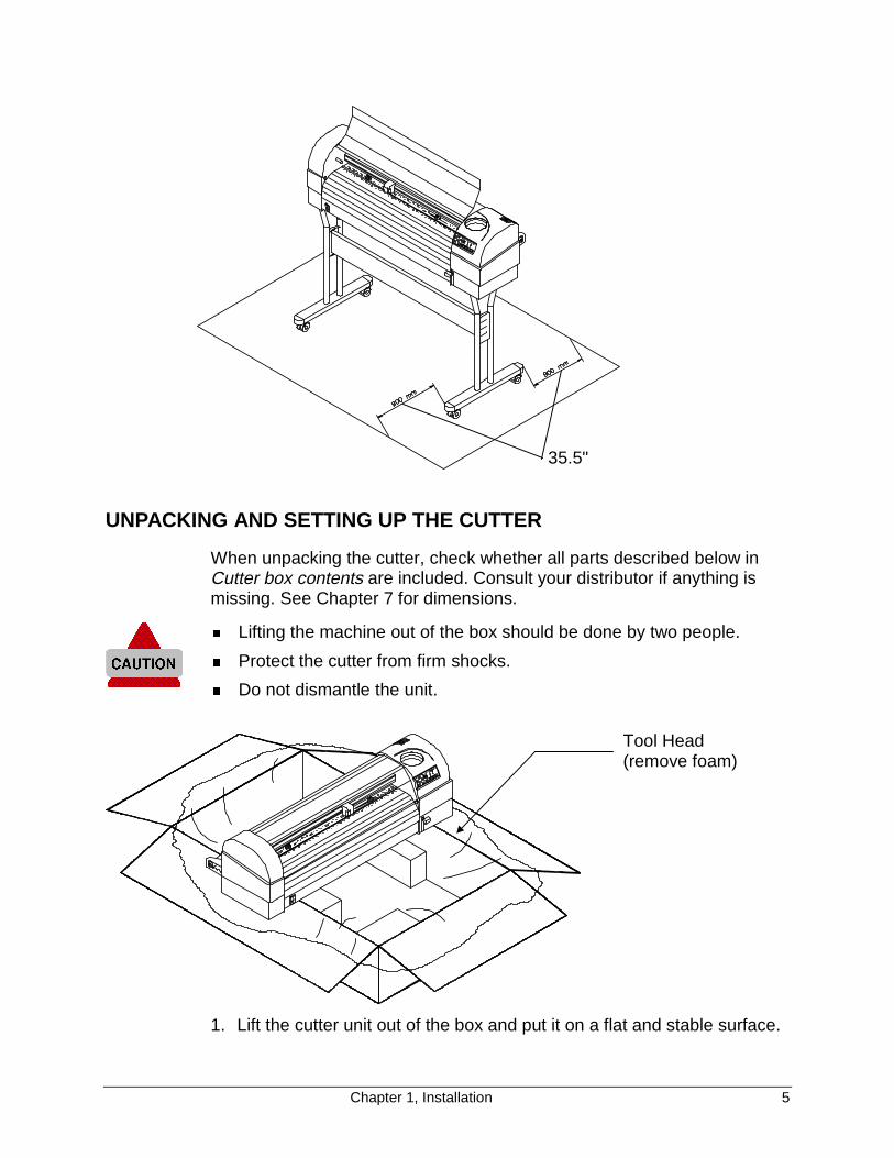
Chapter 1, Installation 5
UNPACKING AND SETTING UP THE CUTTER
When unpacking the cutter, check whether all parts described below inCutter box contents are included. Consult your distributor if anything ismissing. See Chapter 7 for dimensions.
� Lifting the machine out of the box should be done by two people.
� Protect the cutter from firm shocks.
� Do not dismantle the unit.
1. Lift the cutter unit out of the box and put it on a flat and stable surface.
35.5"
Tool Head(remove foam)
6 Chapter 1, Installation
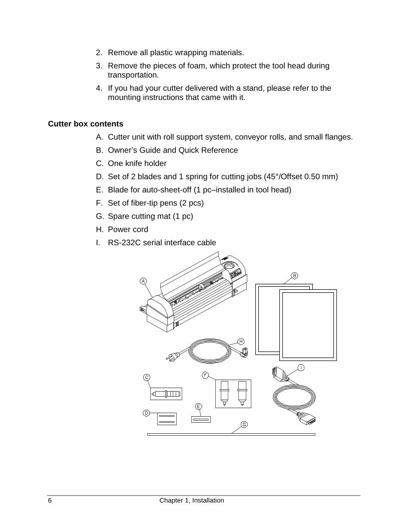
2. Remove all plastic wrapping materials.
3. Remove the pieces of foam, which protect the tool head duringtransportation.
4. If you had your cutter delivered with a stand, please refer to themounting instructions that came with it.
Cutter box contents
A. Cutter unit with roll support system, conveyor rolls, and small flanges.
B. Owner’s Guide and Quick Reference
C. One knife holder
D. Set of 2 blades and 1 spring for cutting jobs (45°/Offset 0.50 mm)
E. Blade for auto-sheet-off (1 pc–installed in tool head)
F. Set of fiber-tip pens (2 pcs)
G. Spare cutting mat (1 pc)
H. Power cord
I. RS-232C serial interface cable
Chapter 1, Installation 7
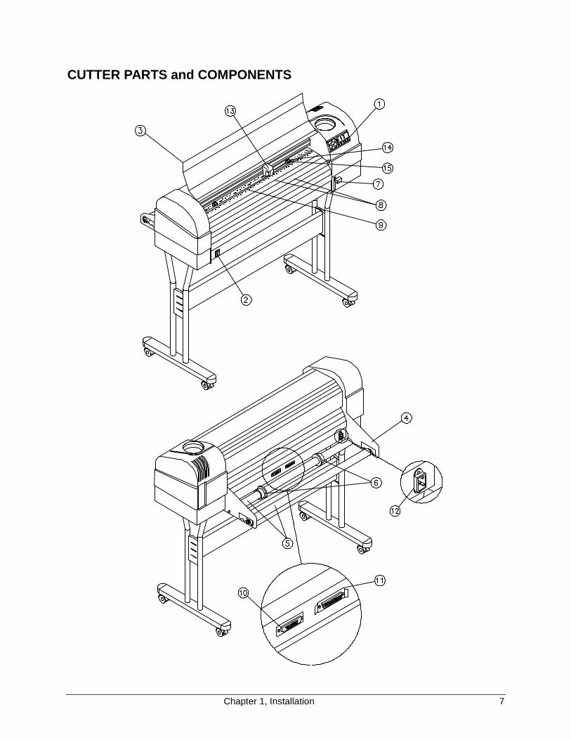
CUTTER PARTS and COMPONENTS

8 Chapter 1, Installation
The numbers in the diagram match the parts described below.
1. Control Panel: Indicator LEDs and control keys.
2. Power Switch: Turns the cutter on or off.
3. Carriage Cover: For safety reasons, the cutter will not work with thecover open. The cover also prevents objects from falling into thecutting zone.
4. Roll Support System: Carries the conveyor rolls.
5. Conveyor Rolls: Hold roll material.
6. Guiding Flanges: Located on the conveyor rolls, prevent the roll ofmaterial from shifting to the left or right when material is pulled from theroll.
7. Material Hold Lever: Raises and lowers the pressure rollers. Loweringthe pressure rollers holds the material in place.
8. Platen and Drive Roller Cover: Supports the cutting material andguides the movement of the material along the X-axis.
9. Cutting Mat: Provides a reliable cutting surface and prevents damageto the knife tip.
10. Serial Interface Connector: RS-232C serial interface connector toconnect the cutter to the host computer.
11. Parallel Interface Connector: Centronics parallel connector toconnect the cutter to the host computer's printer port for fast datatransfer.
12.Power Connector: Connector for the power cord, which plugs into themain power supply of the cutter.
13.Tool head with Tool Mounting Bracket: All available tools such asknife holders, drawing pens, and painting pens can be secured into thetool head using the locking screw. The tool head moves along the Y-axis to the exact cutting position.
14.Drive Rollers: Move the cutting material along the X-axis.
15.Pressure Rollers: Hold the material against the drive rollers duringcutting.
Chapter 1, Installation 9
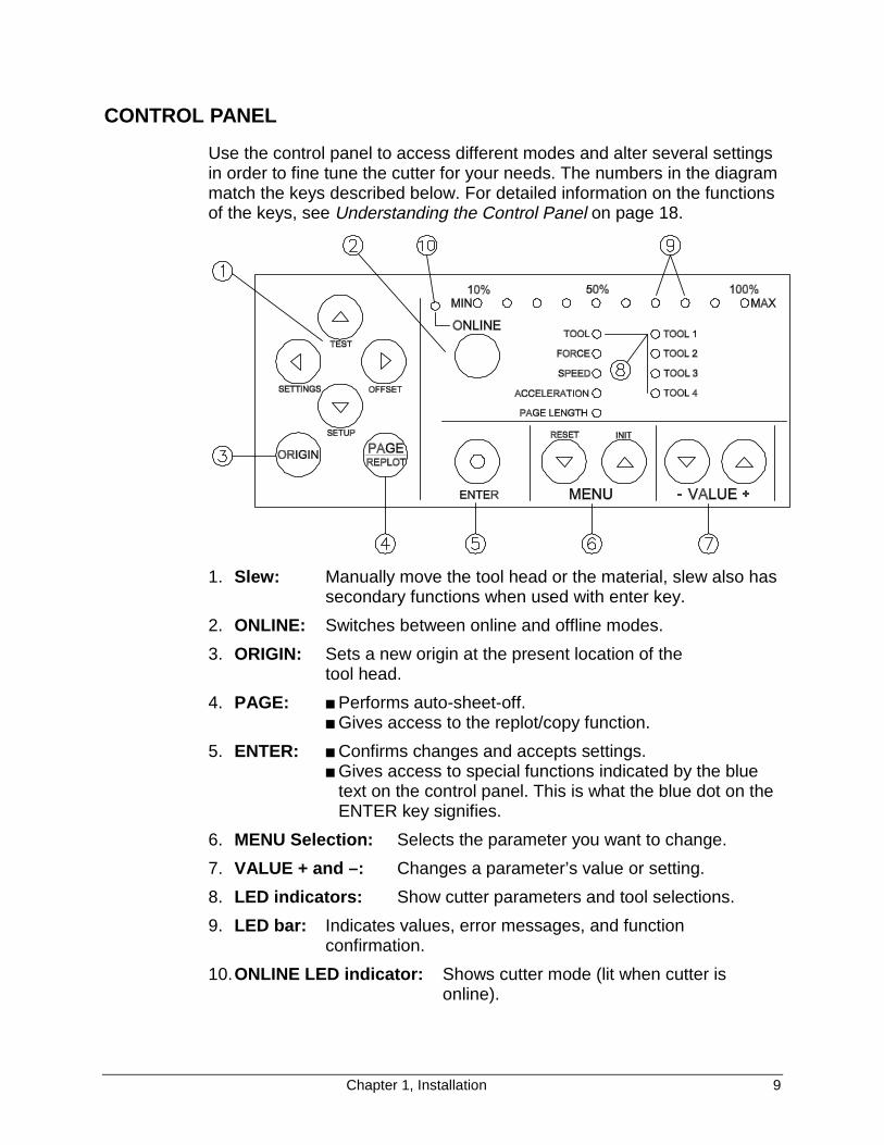
CONTROL PANEL
Use the control panel to access different modes and alter several settingsin order to fine tune the cutter for your needs. The numbers in the diagrammatch the keys described below. For detailed information on the functionsof the keys, see Understanding the Control Panel on page 18.
1. Slew: Manually move the tool head or the material, slew also hassecondary functions when used with enter key.
2. ONLINE: Switches between online and offline modes.
3. ORIGIN: Sets a new origin at the present location of the tool head.
4. PAGE: ■ Performs auto-sheet-off.■ Gives access to the replot/copy function.
5. ENTER: ■ Confirms changes and accepts settings.■ Gives access to special functions indicated by the blue
text on the control panel. This is what the blue dot on theENTER key signifies.
6. MENU Selection: Selects the parameter you want to change.
7. VALUE + and –: Changes a parameter’s value or setting.
8. LED indicators: Show cutter parameters and tool selections.
9. LED bar: Indicates values, error messages, and functionconfirmation.
10. ONLINE LED indicator: Shows cutter mode (lit when cutter isonline).
10 Chapter 1, Installation
Do not use sharp or pointed tools like pens or pencils to press controlpanel keys. Press the keys with your fingertips only.
CONNECTING THE CUTTER TO THE COMPUTER
Serial interface
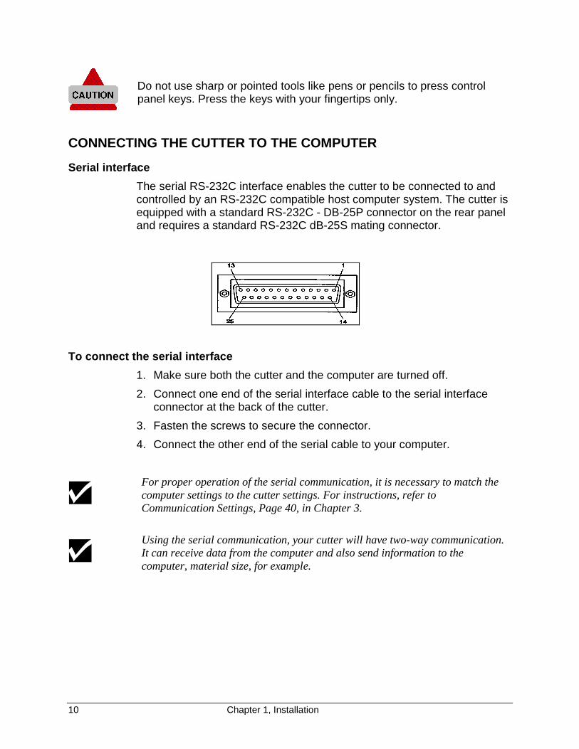
The serial RS-232C interface enables the cutter to be connected to andcontrolled by an RS-232C compatible host computer system. The cutter isequipped with a standard RS-232C - DB-25P connector on the rear paneland requires a standard RS-232C dB-25S mating connector.
To connect the serial interface
1. Make sure both the cutter and the computer are turned off.
2. Connect one end of the serial interface cable to the serial interfaceconnector at the back of the cutter.
3. Fasten the screws to secure the connector.
4. Connect the other end of the serial cable to your computer.
For proper operation of the serial communication, it is necessary to match thecomputer settings to the cutter settings. For instructions, refer toCommunication Settings, Page 40, in Chapter 3.
Using the serial communication, your cutter will have two-way communication.It can receive data from the computer and also send information to thecomputer, material size, for example.

Chapter 1, Installation 11
CONNECTING THE POWER CABLE
1. Make sure the cutter’s power switch is turned off.
2. Plug the cutter end of the power cable into the connector at the back ofthe cutter.
3. Plug the other end of the power cable into an electrical outlet of thecorrect voltage and with a proper grounding.
The illustration above shows an international AC plug.
12 Chapter 1, Installation
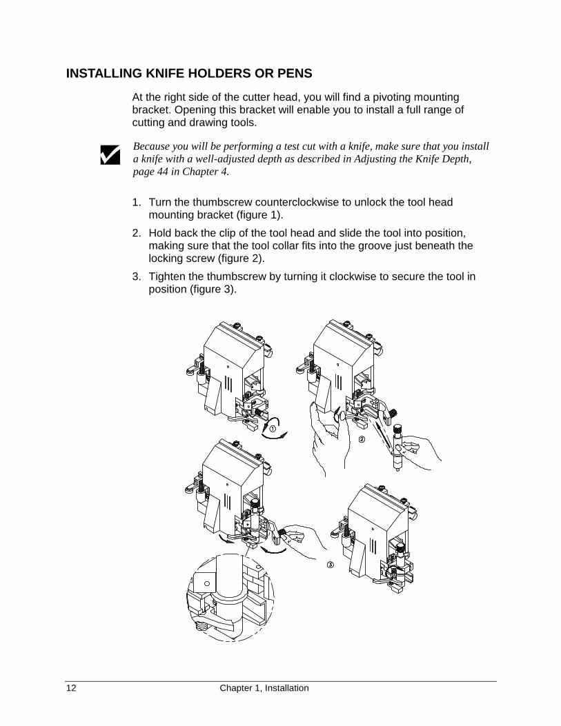
INSTALLING KNIFE HOLDERS OR PENS
At the right side of the cutter head, you will find a pivoting mountingbracket. Opening this bracket will enable you to install a full range ofcutting and drawing tools.
Because you will be performing a test cut with a knife, make sure that you installa knife with a well-adjusted depth as described in Adjusting the Knife Depth,page 44 in Chapter 4.
1. Turn the thumbscrew counterclockwise to unlock the tool headmounting bracket (figure 1).
2. Hold back the clip of the tool head and slide the tool into position,making sure that the tool collar fits into the groove just beneath thelocking screw (figure 2).
3. Tighten the thumbscrew by turning it clockwise to secure the tool inposition (figure 3).
Chapter 1, Installation 13
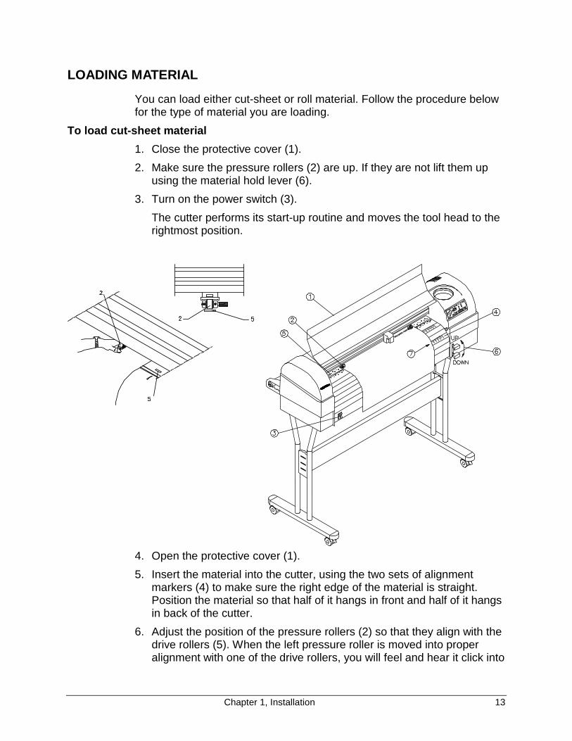
LOADING MATERIAL
You can load either cut-sheet or roll material. Follow the procedure belowfor the type of material you are loading.
To load cut-sheet material
1. Close the protective cover (1).
2. Make sure the pressure rollers (2) are up. If they are not lift them upusing the material hold lever (6).
3. Turn on the power switch (3).
The cutter performs its start-up routine and moves the tool head to therightmost position.
4. Open the protective cover (1).
5. Insert the material into the cutter, using the two sets of alignmentmarkers (4) to make sure the right edge of the material is straight.Position the material so that half of it hangs in front and half of it hangsin back of the cutter.
6. Adjust the position of the pressure rollers (2) so that they align with thedrive rollers (5). When the left pressure roller is moved into properalignment with one of the drive rollers, you will feel and hear it click into
14 Chapter 1, Installation
place. The right pressure roller’s movement is limited so that it cannever be positioned incorrectly.
7. Always make sure that all pressure rollers are completely inside thesheet of material you want to load, so that the rollers do not run on thevery edge of the material. When you use a cut-sheet that does nothave perfectly square corners, it is best to put the pressure rollers atleast ¼" inside the material edge as the width of the sheet may vary.
If you are using a FasTrack 1000 or larger, you have the option of using eithertwo or three pressure rollers, depending on the width of the material you areusing. When not using the left pressure roller (i.e. when loading material of asmall width), the left pressure roller should be placed at the extreme left of thecutter (not on top of a drive roller).
The middle pressure roller should always be placed on top of a drive roller.
8. Put the material hold down lever (6) down and close the cover.
The material loading sequence begins, during which the cutter willmeasure the loaded sheet. The cutter shuffles the material back andforth, determining its size and allowing you to ensure that the materialmoves easily through the cutter.
Do not try to move the pressure rollers when the material hold lever isdown, as this may damage the system.
After the material loading sequence, the tool head is parked at theorigin position and the cutter is online, ready to receive data from thehost computer.
Chapter 1, Installation 15
To load roll material
1. Close the protective cover (1).
The numbers in parentheses refer to the numbers on the illustration on page 13.
2. Make sure the pressure rollers (2) are up. If they are not, put them upusing the material hold lever (6).
3. Turn on the power switch (3).
The cutter performs its start-up routine and moves the tool head to therightmost position.
4. Position the roll of material onto the conveyor rolls. Open theprotective cover, pull the material through, and position the material foroptimal cutting by locating the right edge of the material over therightmost drive roller, and the left edge of the material over one of theother drive rollers.
5. Adjust the position of the pressure rollers (2) so that they align with thedrive rollers (5) and can accommodate the roll of material. When theleft pressure roller is moved into proper alignment with one of the drive
Rollmaterial
Conveyorrolls
Guidingflange

16 Chapter 1, Installation
rollers, you will feel and hear it click into place. The right pressureroller's movement is limited so that it can never be positionedincorrectly. Always make sure that both pressure rollers are at least0.2" (5 mm) inside the edge of the material. Do not let the rollers run onthe very edge of the material.
Do not use the marker lines to align a roll of material! They are for use with cut-sheets only! Rolls can only be correctly installed using the EQUAL TENSIONMETHOD!
If you are using a FasTrack 1000 or larger, you can use either two or threepressure rollers, depending on the width of the material used. When not usingthe left pressure roller (i.e. when loading material of a small width), the leftpressure roller should be placed at the extreme left of the cutter (not on top of adrive roller).
The middle pressure roller should always be placed on top of a drive roller.
6. Hold the front edge of the material in the middle with one hand andwith the other hand, the roll itself. As you are holding the roll firmly inposition, pull the front edge of the material forward so that there is aneven tension across the whole width of the roll (= Equal Tensionmethod.)
The material must be rolled tightly and not telescoped.
7. Adjust the position of the guiding flanges so that they are justalongside the roll of material, but not directly against it.
8. Close the protective cover.
9. This action starts the material loading sequence, during which thecutter shuffles a pre-set length of material. The material will be shuffledback and forth allowing you to make sure the material moves easilythrough the cutter. The shuffle length is factory-set to 40" (1 m), butyou can adjust the setting if desired. (See Page Length, page 27, inChapter 2).
10. After the material loading sequence, the tool head is parked at theorigin position and the cutter is online, ready to receive data from thehost computer.
Chapter 1, Installation 17
To straighten the material edge using the auto-sheet-off utility
The auto-sheet-off mechanism of the cutter can easily cut the front edgeof a new roll of material straight as well as cut off a sheet of material froma roll, to be used as a separate sheet.
To do this, proceed as follows:
1. Insert the material to be cut (straight) into the cutter as if you wereloading either a roll or a cut sheet, as described above.
2. Make sure the material hold lever is up.
3. Press the PAGE key to request a sheet-off sequence. You will getvisual confirmation of your request by the LED bar, which shows aflashing sequence of LEDs.
4. Lower the material hold lever and close the cutter’s cover to start thesequence.
The cutter sheets off the material, producing a neat edge.
The default FORCE used for automatic sheet-off is 300 grams. To adjust thisforce, see Force Selection, page 25, in Chapter 2.
18 Chapter 2, Cutter Controls
CHAPTER 2CUTTER CONTROLS
UNDERSTANDING THE CONTROL PANEL
The control panel contains 12 keys that perform one or more functions,such as positioning the tool head, selecting online mode, performing testcuts, changing settings, and more. All of the keys and their functions aredescribed in detail below.
There are also 20 LEDs that provide information about the status of thecutter. Ten of them constitute the LED bar on top of the control panel,indicating values or showing error messages. All the other LEDs show theonline status of the cutter, which tool selection is in use and whichparameter has been selected.
Online and Offline modes
The ONLINE key is used to switch between the online and the offlinemodes of your cutter. Each operating mode allows you to perform adifferent set of tasks from the control panel as described below.
When you first switch the cutter on
� with no material loaded, the cutter is in offline mode and theONLINE LED is off.
� with material already loaded, the cutter is automatically in onlinemode and the ONLINE LED is lit.
After you load material, the cutter automatically goes online.
Chapter 2, Cutter Controls 19
In online mode you can:
� Set a new origin
� Initiate a sheet-off action
� Browse through the parameter settings without changing them
In offline mode, you are in control of the cutter and can alter the cuttersettings such as
Tool Force SpeedAccelerations Page Length Origin
Slew keys
TEST
OFFSET
SETUP
SETTINGS
With the slew keys, you can move the tool head and the material so youcan examine specific details of the job or set a new origin (start point). Theslew keys are always active, whether the cutter is online or offline.
When you press the � (left) or � (right) slew key, the tool head moves inthe Y-axis, slowly for 2 seconds and then speeds up.
When you press the � (up) or � (down) slew key, the material (if loaded)moves in the X-axis, slowly for 2 seconds and then speeds up.
ORIGIN key
The ORIGIN key allows you to register a new origin (start) point if materialhas been loaded. A new origin point can be set in offline as well as inonline mode.
To register a new start point
1. Using the slew keys, place the tool head at the desired origin point.
2. Press the ORIGIN key. LEDs on the LED bar will flash to confirm youraction.
If the tool head Is located beyond the borders of the material, the new originpoint will be rejected.

20 Chapter 2, Cutter Controls
PAGE key
PAGE
REPLOT
The PAGE key is available only in online mode. It has two functions:� Function 1: To perform the Auto-Sheet-Off function. The position
where the auto-sheet-off occurs depends on the situation. If no designhas been cut at the spot where the tool head is parked when pressingthe PAGE key, the cutter will auto-cut at the present location. When adesign has already been cut, the tool head will move to a location 0.2"(5 mm) beyond the job and will perform an auto-cut.
� Function 2: To start the automatic replot/sheet-off function of the lastfile that was sent to the cutter—all data that was sent since the lastINITIALIZATION (“IN”) command. Proceed as follows:
1. Press the PAGE key for about two seconds.
On the LED bar, an LED will start blinking. Its position in the barindicates the number of copies to be cut. For example, 60% means6 copies.
2. Using the VALUE +/- keys, select the desired number of copies.The factory default settings allow a maximum of 10 copies.
3. Press ENTER.The cutter starts cutting. A new part of the material will be loadedautomatically after every replot.
It is possible to request up to 100 copies by changing the REPLOTMULTIPLICATION FACTOR in the cutter setup. (See Replot Factor, page 38,in Chapter 3.
ENTER key
You must press the ENTER key to confirm requested changes to thecutter settings. A requested change will always be shown by one or moreflashing LEDs for the parameter to be changed. Pressing ENTER willstop the flashing, indicating that the new setting has been accepted.
The ENTER key also carries a blue dot, indicating it can be pressedtogether with another key to access one of the special functions indicatedin blue on the control panel.
Chapter 2, Cutter Controls 21
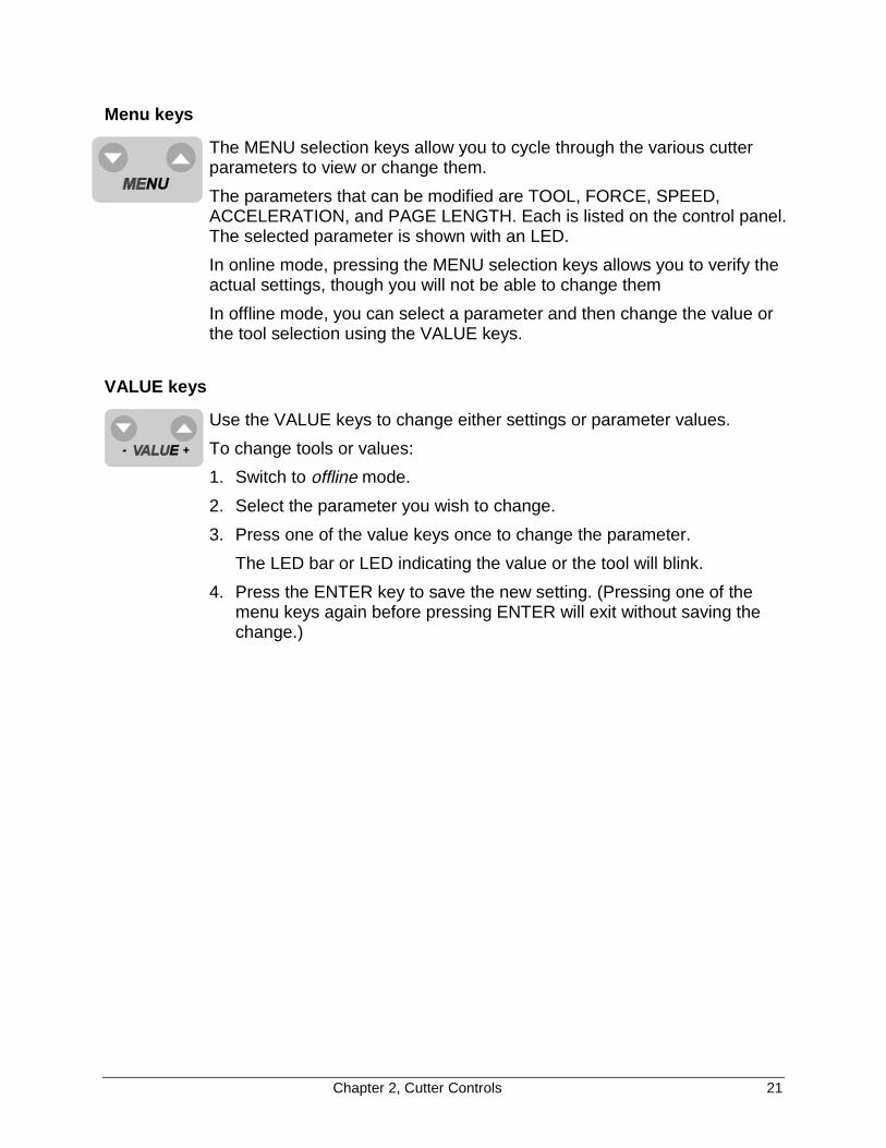
Menu keys
The MENU selection keys allow you to cycle through the various cutterparameters to view or change them.
The parameters that can be modified are TOOL, FORCE, SPEED,ACCELERATION, and PAGE LENGTH. Each is listed on the control panel.The selected parameter is shown with an LED.
In online mode, pressing the MENU selection keys allows you to verify theactual settings, though you will not be able to change them
In offline mode, you can select a parameter and then change the value orthe tool selection using the VALUE keys.
VALUE keys
Use the VALUE keys to change either settings or parameter values.
To change tools or values:
1. Switch to offline mode.
2. Select the parameter you wish to change.
3. Press one of the value keys once to change the parameter.
The LED bar or LED indicating the value or the tool will blink.
4. Press the ENTER key to save the new setting. (Pressing one of themenu keys again before pressing ENTER will exit without saving thechange.)

22 Chapter 2, Cutter Controls
GENERAL PROCEDURE TO CHANGE SETTINGS ON THE CUTTER
1. Make sure you have power to the cutter and that the cutter is in theoffline mode.
If you start with the cutter off (no power),
� and there is no material loaded, the cutter will be in offline mode,which is indicated by the ONLINE LED being off.
� and there is material loaded, the cutter will be in online mode,which is indicated by the ONLINE LED being lit. Press the ONLINEkey to take the cutter offline, which will be indicated by the ONLINELED going out.
If you start with the cutter on (power to the cutter), look at the ONLINELED,
� if it is lit, press the ONLINE key to put the cutter in the offline mode.The ONLINE LED will go off.
� if it is off, the cutter is already in the offline mode.
2. Using the MENU keys, select one of the five different parameters(TOOL, FORCE, SPEED, ACCELERATION, or PAGE LENGTH).
3. Using the VALUE keys, adjust the settings for the selected parameter.The + key increases the value or selects the next parameter. The - keydecreases the value or selects the previous parameter. A requestedchange is indicated by one or several blinking LEDs.
4. Press ENTER to confirm the requested change. (To exit without achange, press one of the menu keys.)
The blinking stops, indicating that the new setting has been saved.

Chapter 2, Cutter Controls 23
TOOL SELECTION
The four tools listed on the control panel are actually four different sets oftool parameters. For each of the four tools you can register and storespecific values for
TOOLKIND (knife, drawing pen, or pounce)FORCESPEEDACCELERATIONOFFSET (knives only)POUNCING GAP (pouncing only).
Switching from tool to tool allows you to switch from one complete setup toanother without having to change any individual value.
Furthermore, to fit your application, you can change the settings in each ofthe four setups. This allows you to save the settings for your most popularmaterial or job types. Then you can swiftly change to a different materialtype or application without having to change any of the settings.
(Offset values and correction routines are applied only if a tool is selectedthat is defined as a knife. The pouncing gap is only adjustable and active ifa tool is selected that is defined as a pouncing tool.)
There is a fifth tool parameter, TOOL-UP, which is not listed on the controlpanel. When tool-up is selected, you can adjust speed and accelerationfor tool-up movements as well as the force used to perform automaticsheet-off. (The force and acceleration settings included in the four toolsettings are for tool-down movements.)
The procedure below tells you how to choose the tool (setup). Thefollowing sections explain how to change the settings in the setup.
To select which set of tool parameters to use or change
1. Switch the cutter offline.
2. Using the MENU selection keys, select the TOOL option.
The LED next to TOOL must go on.
3. Using the VALUE + or – key, select TOOL 1, TOOL 2, TOOL 3, TOOL4 or TOOL-UP.
TOOL-UP is selected when all TOOL LEDs are out. The other toolsare indicated by blinking of the associated LED.
4. Press ENTER to confirm your selection or press one of the menu keysto exit. To access the TOOL-UP status, you also need to pressENTER, although no flashing LED is visible at that time!
24 Chapter 2, Cutter Controls
� For cutting jobs, use only tools set to KNIFE.
� For plotting jobs, use only tools set to PEN.
� For pouncing jobs, use only tools set to POUNCE.
� When TOOL-UP is selected, the FORCE adjustment refers tothe FORCE that will be used for automatic sheet-off.
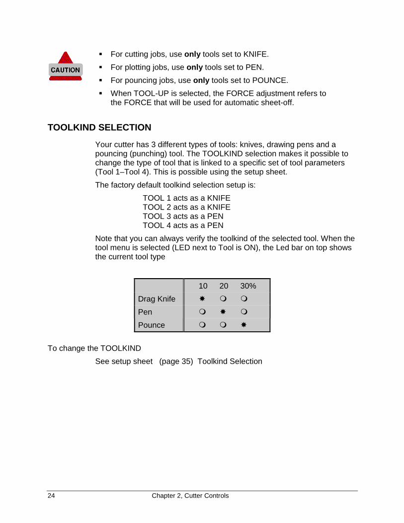
TOOLKIND SELECTION
Your cutter has 3 different types of tools: knives, drawing pens and apouncing (punching) tool. The TOOLKIND selection makes it possible tochange the type of tool that is linked to a specific set of tool parameters(Tool 1–Tool 4). This is possible using the setup sheet.
The factory default toolkind selection setup is:
TOOL 1 acts as a KNIFETOOL 2 acts as a KNIFETOOL 3 acts as a PENTOOL 4 acts as a PEN
Note that you can always verify the toolkind of the selected tool. When thetool menu is selected (LED next to Tool is ON), the Led bar on top showsthe current tool type
10 20 30%
Drag Knife �
Pen �
Pounce �
To change the TOOLKIND
See setup sheet (page 35) Toolkind Selection

Chapter 2, Cutter Controls 25
FORCE SELECTION
Force is the amount of downward pressure applied by a tool. You are ableto adjust the amount of tool pressure applied by an individual tool so thatyou can cut varying thicknesses of material correctly or set the correctamount of pressure for a pen.
1. Switch the cutter offline.
2. Using the MENU selection keys, select the FORCE option (LED next toFORCE must be on).
The actual FORCE setting for the selected tool will now be shown onthe LED bar. You can view the value in both offline and online modes.
3. Using the VALUE +/- keys, you can now alter the FORCE settings.
The force is adjustable in three ranges:
15-100 grams, 110-190 grams, and 200-500 grams.(See explanation on the next page.)
4. Press ENTER to confirm and store, or press one of the menu keys toexit.
For the procedure to test the force, see Cutting a Test Square To Test CuttingPressure (Force), page 49, in Chapter 4.
26 Chapter 2, Cutter Controls
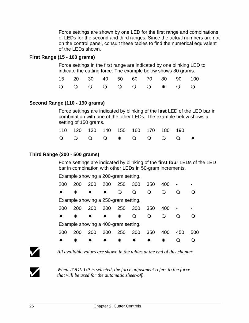
Force settings are shown by one LED for the first range and combinationsof LEDs for the second and third ranges. Since the actual numbers are noton the control panel, consult these tables to find the numerical equivalentof the LEDs shown.
First Range (15 - 100 grams)
Force settings in the first range are indicated by one blinking LED toindicate the cutting force. The example below shows 80 grams.
15 20 30 40 50 60 70 80 90 100
�
Second Range (110 - 190 grams)
Force settings are indicated by blinking of the last LED of the LED bar incombination with one of the other LEDs. The example below shows asetting of 150 grams.
110 120 130 140 150 160 170 180 190
� �
Third Range (200 - 500 grams)
Force settings are indicated by blinking of the first four LEDs of the LEDbar in combination with other LEDs in 50-gram increments.
Example showing a 200-gram setting.
200 200 200 200 250 300 350 400 - -
� � � �
Example showing a 250-gram setting.
200 200 200 200 250 300 350 400 - -
� � � � �
Example showing a 400-gram setting.
200 200 200 200 250 300 350 400 450 500
� � � � � � � �
All available values are shown in the tables at the end of this chapter.
When TOOL-UP is selected, the force adjustment refers to the forcethat will be used for the automatic sheet-off.

Chapter 2, Cutter Controls 27
SPEED SELECTION
The speed selection allows you to set the tool-down speed, the speed atwhich the tool moves through the material.
1. Switch the cutter offline.
2. Using the MENU selection keys, select the SPEED option (LED next toSPEED must be on).
The current SPEED setting for the selected tool is shown on the LEDbar. You can view the value both offline as and online modes.
3. Use the VALUE +/- keys to change the SPEED setting.
4. Press ENTER to confirm and store, or press one of the menu keys toexit.
The indicated value only refers to the tool-down speed of the selected tool.The tool-up speed can be set separately (See Tool Selection page 23, inthis Chapter.
All values being used or available are shown in the tables at the end ofthis chapter.
ACCELERATION SELECTION
1. Switch the cutter offline.
2. Using the MENU selection keys, select the ACCELERATION option(LED next to ACCELERATION must be on).
The current ACCELERATION setting for the selected tool is shown onthe LED bar. You can view the value in both offline and online modes.
3. Use the VALUE +/- keys to change the ACCELERATION settings.
4. Press ENTER to confirm and store, or press one of the menu keys toexit.
All values being used or available are shown in the tables at the end ofthis chapter.
PAGE LENGTH
This parameter is related to loading roll material. The PAGE LENGTHmust be set before a roll is loaded. Set the PAGE LENGTH to a value atleast as large as the job you are going to cut.

28 Chapter 2, Cutter Controls
There are three reasons for using a PAGE LENGTH:
� The length of material set for the PAGE LENGTH is pulled off the rollbefore the cutting job starts, thus preventing material from being pulledoff the roll at high speed and acceleration. High speed movements—up to 40 ips, (1000 mm/s) and 4.0 G—can be achieved only when thematerial can move freely without having to be pulled off the roll duringa job.
� Before cutting starts, the complete length of the material is shuffledback and forth through the cutter, ensuring that the pressure rollershave a clear path while you have the time to verify that the materialmoves easily through the cutter
� The Auto-Sheet-Off feature automatically cuts off material at the end ofa cutting sequence. Following an automatic PAGE command or amanual PAGE command from the control panel, the cutter shufflesthrough the pre-set PAGE LENGTH of material to ensure that there isenough material left for a possible replot. If there is not enoughmaterial left, the cutter will stop before the end of the assigned materiallength.
To set the PAGE LENGTH
1. Switch the cutter offline.
2. Using the MENU selection keys, select the PAGE LENGTH option(LED next to PAGE LENGTH must be on).
The current PAGE LENGTH setting is shown on the LED bar. You canview the value in both offline and online modes.
3. Use the VALUE +/- keys to change the PAGE LENGTH settings. Setthe PAGE LENGTH to a value that is at least as large as the sign youwant to cut. The available values for PAGE LENGTH are:
in 0 16 24 32 40 80 120 160 200 400
cm 0 40 60 80 100 200 300 400 500 1000Each value corresponds with the indications shown on the LED bar.The default PAGE LENGTH is 40" (1 m).
4. Press ENTER to confirm and store, or press one of the menu keys toexit.
The use of the PAGE LENGTH should not be regarded as a waste of time. If theshuffle movement completes without difficulty, the job to be cut will be executedwith very little risk of material tracking problems. In the long run, this savestime because you won't have to re-cut a complex design because of badmaterial alignment.
Chapter 2, Cutter Controls 29
The cutting range is not limited by the Page Length that you have set. If adesign that exceeds the shuffle length is sent to the cutter, it will react asfollows:� The first vector that exceeds the limit will be cut using reduced speed for the
distance exceeding the limit.
� An additional 8" (20 cm) of material will be pulled from the roll in order toeliminate any possible snagging at the roll.
� After the additional 8" (20 cm) pre-feed, the cutter will continue at therequested speed until the new limit is exceeded.
These protective measures should not be a reason to avoid changing the pagelength, since by not changing it, you will be unable to check the full materialtransport before the job is launched.
RESET and CLEAR FUNCTION
In some cases it might be necessary to reset your cutter and/or clear itsbuffer while a cutting job is in progress. To do this:
1. Cancel the cutting job in your cutter software so that the data flow isstopped.
2. Press the ENTER and the MENU down key (RESET) at the same timefor about two seconds.
A sequence of flashing LEDs on the LED bar will indicate that thecutter has cancelled the current job. The buffer is now empty and thecutter has stopped cutting.
This reset procedure reinstalls the default original.
30 Chapter 2, Cutter Controls
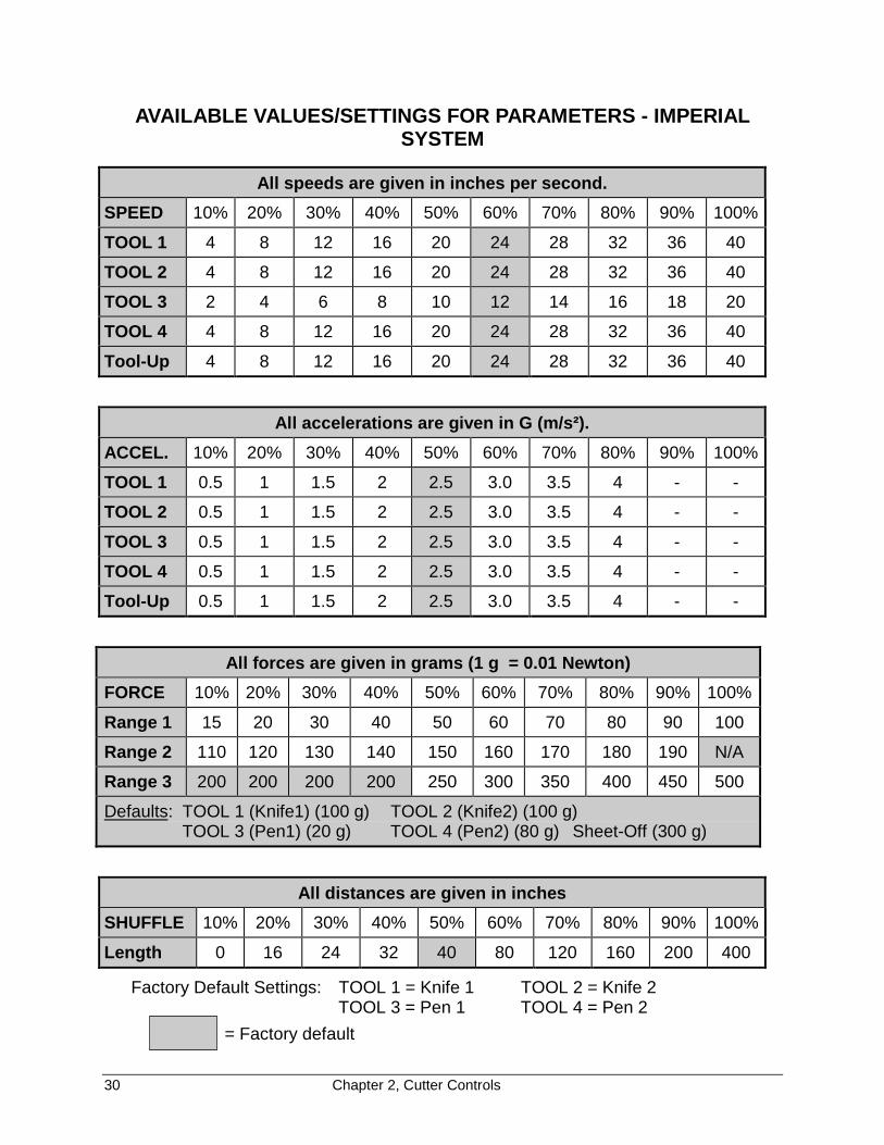
AVAILABLE VALUES/SETTINGS FOR PARAMETERS - IMPERIALSYSTEM
All speeds are given in inches per second.
SPEED 10% 20% 30% 40% 50% 60% 70% 80% 90% 100%
TOOL 1 4 8 12 16 20 24 28 32 36 40
TOOL 2 4 8 12 16 20 24 28 32 36 40
TOOL 3 2 4 6 8 10 12 14 16 18 20
TOOL 4 4 8 12 16 20 24 28 32 36 40
Tool-Up 4 8 12 16 20 24 28 32 36 40
All accelerations are given in G (m/s²).
ACCEL. 10% 20% 30% 40% 50% 60% 70% 80% 90% 100%
TOOL 1 0.5 1 1.5 2 2.5 3.0 3.5 4 - -
TOOL 2 0.5 1 1.5 2 2.5 3.0 3.5 4 - -
TOOL 3 0.5 1 1.5 2 2.5 3.0 3.5 4 - -
TOOL 4 0.5 1 1.5 2 2.5 3.0 3.5 4 - -
Tool-Up 0.5 1 1.5 2 2.5 3.0 3.5 4 - -
All forces are given in grams (1 g = 0.01 Newton)
FORCE 10% 20% 30% 40% 50% 60% 70% 80% 90% 100%
Range 1 15 20 30 40 50 60 70 80 90 100
Range 2 110 120 130 140 150 160 170 180 190 N/A
Range 3 200 200 200 200 250 300 350 400 450 500
Defaults: TOOL 1 (Knife1) (100 g) TOOL 2 (Knife2) (100 g)TOOL 3 (Pen1) (20 g) TOOL 4 (Pen2) (80 g) Sheet-Off (300 g)
All distances are given in inches
SHUFFLE 10% 20% 30% 40% 50% 60% 70% 80% 90% 100%
Length 0 16 24 32 40 80 120 160 200 400
Factory Default Settings: TOOL 1 = Knife 1 TOOL 2 = Knife 2TOOL 3 = Pen 1 TOOL 4 = Pen 2
= Factory default
Chapter 2, Cutter Controls 31
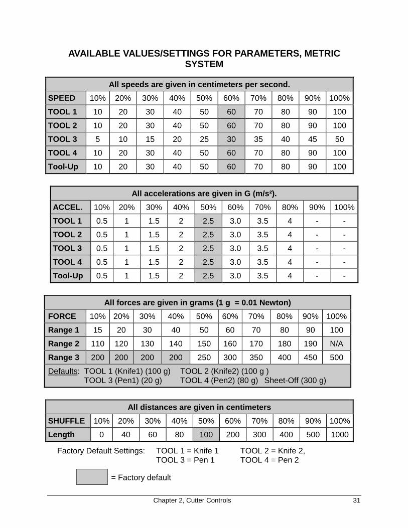
AVAILABLE VALUES/SETTINGS FOR PARAMETERS, METRICSYSTEM
All speeds are given in centimeters per second.
SPEED 10% 20% 30% 40% 50% 60% 70% 80% 90% 100%
TOOL 1 10 20 30 40 50 60 70 80 90 100
TOOL 2 10 20 30 40 50 60 70 80 90 100
TOOL 3 5 10 15 20 25 30 35 40 45 50
TOOL 4 10 20 30 40 50 60 70 80 90 100
Tool-Up 10 20 30 40 50 60 70 80 90 100
All accelerations are given in G (m/s²).
ACCEL. 10% 20% 30% 40% 50% 60% 70% 80% 90% 100%
TOOL 1 0.5 1 1.5 2 2.5 3.0 3.5 4 - -
TOOL 2 0.5 1 1.5 2 2.5 3.0 3.5 4 - -
TOOL 3 0.5 1 1.5 2 2.5 3.0 3.5 4 - -
TOOL 4 0.5 1 1.5 2 2.5 3.0 3.5 4 - -
Tool-Up 0.5 1 1.5 2 2.5 3.0 3.5 4 - -
All forces are given in grams (1 g = 0.01 Newton)
FORCE 10% 20% 30% 40% 50% 60% 70% 80% 90% 100%
Range 1 15 20 30 40 50 60 70 80 90 100
Range 2 110 120 130 140 150 160 170 180 190 N/A
Range 3 200 200 200 200 250 300 350 400 450 500
Defaults: TOOL 1 (Knife1) (100 g) TOOL 2 (Knife2) (100 g )TOOL 3 (Pen1) (20 g) TOOL 4 (Pen2) (80 g) Sheet-Off (300 g)
All distances are given in centimeters
SHUFFLE 10% 20% 30% 40% 50% 60% 70% 80% 90% 100%
Length 0 40 60 80 100 200 300 400 500 1000
Factory Default Settings: TOOL 1 = Knife 1 TOOL 2 = Knife 2,TOOL 3 = Pen 1 TOOL 4 = Pen 2
= Factory default
32 Chapter 3, Cutter Settings and Special Functions
CHAPTER 3CUTTER SETTINGS and SPECIAL FUNCTIONS
INTRODUCTION
Most of the frequently-used settings are available directly from thekeyboard. However, when setting up the cutter, you must fine tune it tomatch the computer setup. Furthermore, the MENU mode operation givesyou access to the setup sheet, allowing you to change special functionsthat are not used frequently.
This chapter contains information on how to enter the MENU mode, plotthe setup sheet, and use it to change 32 different settings.
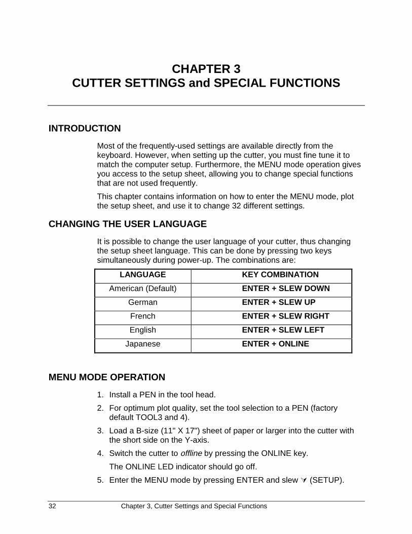
CHANGING THE USER LANGUAGE
It is possible to change the user language of your cutter, thus changingthe setup sheet language. This can be done by pressing two keyssimultaneously during power-up. The combinations are:
LANGUAGE KEY COMBINATION
American (Default) ENTER + SLEW DOWN
German ENTER + SLEW UP
French ENTER + SLEW RIGHT
English ENTER + SLEW LEFT
Japanese ENTER + ONLINE
MENU MODE OPERATION
1. Install a PEN in the tool head.
2. For optimum plot quality, set the tool selection to a PEN (factorydefault TOOL3 and 4).
3. Load a B-size (11" X 17") sheet of paper or larger into the cutter withthe short side on the Y-axis.
4. Switch the cutter to offline by pressing the ONLINE key.
The ONLINE LED indicator should go off.
5. Enter the MENU mode by pressing ENTER and slew � (SETUP).

Chapter 3, Cutter Settings and Special Functions 33
The cutter now plots a menu selection line (example below).
MENU: xx.xx:1 2 3 4 5 6 7 8 9 10 11 12 13 14 15 16 17 18 19 20 21 22 23 24 25 26 27 28 29 30 31 32 SHOW
You can now plot a complete setup sheet with all the settings and optionsor any of the 32 lines, each showing a single setting and its options. Seethe next page for a sample setup sheet.
To plot a complete setup sheet
1. Using the � or � (left or right slew) key, park the tool head above theSHOW function.
2. Press ENTER.
After your selection is plotted, the tool head is returned to the menuselection line.
To plot a single line and change settings
The column of 32 numbers at the left of the sample setup sheetcorrespond to the row of 32 numbers in the menu selection line.
1. Using the � or � (left or right slew) key, park the tool head above yourselection in the menu selection line.
2. Press ENTER.
After the line is plotted, the tool head is parked above the currentsetting, which is also underlined in the plot.
3. To keep the current setting, use the � or � (up or down) slew key toreturn to the menu selection line.
4. To change the setting, use the � or � (left or right slew) key to positionthe tool head above the desired setting.
5. Press ENTER to save the new setting.
The tool then returns to the menu selection line.
6. To return the cutter to its normal operating mode, put the material holdlever up and remove the setup sheet from the cutter.
Switching the machine off will not undo any changes that have already beensaved, even if the cutter is still in MENU mode operation when you switch it off.
To reset the cutter to factory defaults, there is a special key code sequence. SeeReset to Factory Defaults, page 43, in this chapter.
When you view a parameter in the setup sheet, the current selection of thatparticular parameter is underlined when ENTER is pushed or exit is chosen viathe slew keys.
34 Chapter 3, Cutter Settings and Special Functions
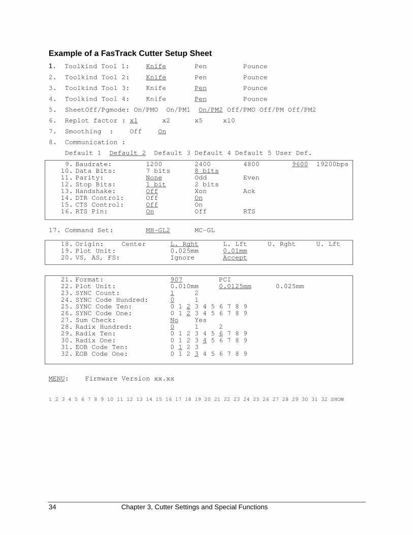
Example of a FasTrack Cutter Setup Sheet
1. Toolkind Tool 1: Knife Pen Pounce
2. Toolkind Tool 2: Knife Pen Pounce
3. Toolkind Tool 3: Knife Pen Pounce
4. Toolkind Tool 4: Knife Pen Pounce
5. SheetOff/Pgmode: On/PMO On/PM1 On/PM2 Off/PMO Off/PM Off/PM2
6. Replot factor : x1 x2 x5 x10
7. Smoothing : Off On
8. Communication :
Default 1 Default 2 Default 3 Default 4 Default 5 User Def.
9. Baudrate: 1200 2400 4800 9600 19200bps 10. Data Bits: 7 bits 8 bits 11. Parity: None Odd Even 12. Stop Bits: 1 bit 2 bits 13. Handshake: Off Xon Ack 14. DTR Control: Off On 15. CTS Control: Off On 16. RTS Pin: On Off RTS
17. Command Set: MH-GL2 MC-GL
18. Origin: Center L. Rght L. Lft U. Rght U. Lft 19. Plot Unit: 0.025mm 0.01mm 20. VS, AS, FS: Ignore Accept
21. Format: 907 PCI 22. Plot Unit: 0.010mm 0.0125mm 0.025mm 23. SYNC Count: 1 2 24. SYNC Code Hundred: 0 1 25. SYNC Code Ten: 0 1 2 3 4 5 6 7 8 9 26. SYNC Code One: 0 1 2 3 4 5 6 7 8 9 27. Sum Check: No Yes 28. Radix Hundred: 0 1 2 29. Radix Ten: 0 1 2 3 4 5 6 7 8 9 30. Radix One: 0 1 2 3 4 5 6 7 8 9 31. EOB Code Ten: 0 1 2 3 32. EOB Code One: 0 1 2 3 4 5 6 7 8 9
MENU: Firmware Version xx.xx
1 2 3 4 5 6 7 8 9 10 11 12 13 14 15 16 17 18 19 20 21 22 23 24 25 26 27 28 29 30 31 32 SHOW
Chapter 3, Cutter Settings and Special Functions 35
GENERAL SETTINGS
The general setting parameters, lines 1 through 7 on the setup sheet,influence the cutter’s reactions to commands given by the computer orinitiated at the control panel. In the general settings menu, you can setTOOLKIND, PAGE MODE, REPLOT FACTOR and SMOOTHING. Here'san example from the setup sheet on the previous page:
1. Toolkind Tool1: Knife Pen Pounce
2. Toolkind Tool2: Knife Pen Pounce
3. Toolkind Tool3: Knife Pen Pounce
4. Toolkind Tool4: Knife Pen Pounce
5. SheetOff/Pgmode: On/PM0 On/PM1 On/PM2 Off/PM0 Off/PM1 Off/PM2
6. Replot Factor: x1 x2 x5 x10
7. Smoothing: Off On
TOOLKIND SELECTION
Lines 1 to 4 of the setup sheet allow you to redefine the toolkind for eachof the four tools. By factory default TOOLS 1 and 2 are defined as knives,while TOOLS 3 and 4 are defined as pens.
For an explanation of the complete setup for the four tools, which is donefrom the control panel, see Tool Selection, Force Selection, SpeedSelection, and Acceleration Selection, starting on page 23, in Chapter 2.
To select a TOOLKIND
The example is for Tool 1.
1. Using the � and � (left and right slew) keys, position the pen aboveselection 1, 2, 3, or 4 in the menu selection line.
2. Press ENTER to confirm this choice.
The cutter plots the following line
1. Toolkind Tool1: Knife Pen Pounce
after which the tool head parks above the current setting.
3. To keep the current setting, use the � and � (up and down) slew keysto return to the menu selection line.
4. To change the setting, use the � and � (left and right slew) keys toposition the tool head above the desired setting.
5. Press the ENTER key to save the new setting into memory.
At the same time, the tool head returns to the menu selection line,allowing a new selection.

36 Chapter 3, Cutter Settings and Special Functions
SHEET-OFF / PAGE MODE
This is a combination of two parameters: sheet-off and page mode. Youcan select any one of three page modes with the auto sheet-off featureturned on or off.
� With the auto-sheet-off part, you can enable or disable the automaticsheet-off facility. When the auto-sheet-off function is disabled, nosheeting off will occur.
� The page mode part determines the cutter’s reaction to a PAGEcommand as sent by the cutting software. The PAGE command isused to relocate the origin after a job is finished and can take controlremotely of the cutter’s automatic sheet-off feature. Sheeting-offautomatically, without user intervention, is a unique feature ofFasTrack cutters that enhances the cutter’s versatility and overallperformance enormously.
Page commandsA PAGE command is sent to the cutter by the host computer software aseither a “PG;”, or “Pgn;”, where “n” is a number in millimeters.
If the PAGE command “PG;” is sent, the cutter will automatically sheet offregardless of the Page Mode, minimizing the loss of material.
If the PAGE command “Pgn;” is sent, the number after the PG commandwill be interpreted differently, depending on the page mode you havechosen:
� Page Mode 0 (PM0): The number after the PAGE command is ignored.The material will be cut 0.2" (0.5 cm) after the furthest vector and thenew cutting limit will be located 0.2" (0.5 cm) from the lower materialborder.
� Page Mode 1 (PM1): The new origin is located “n” millimeters beyondthe last vector that was sent.
� Page Mode 2 (PM2) = default: The new origin is located “n” millimetersbeyond the previous origin position.
Refer to the manual for your software to find out what kind of page mode yoursoftware sends to the cutter.
Chapter 3, Cutter Settings and Special Functions 37
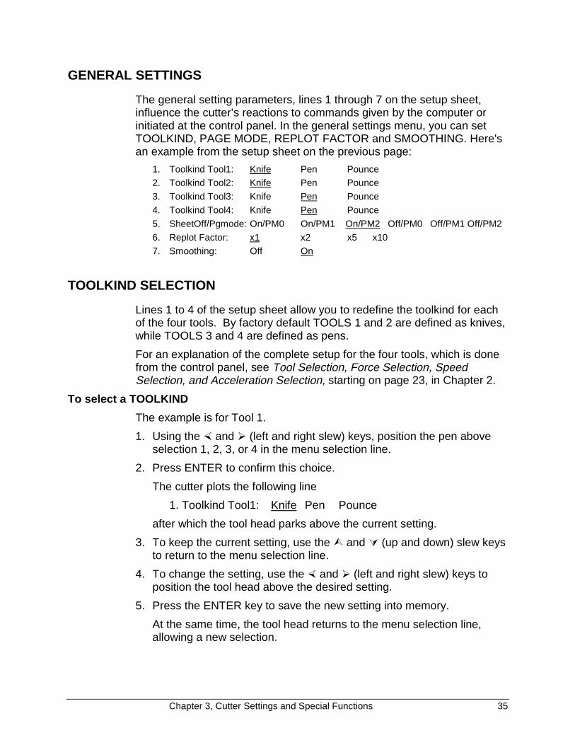
A: Original origin.
B: End point last vector
C: New origin with Page Mode 1
D: New origin with Page Mode 2
To set the SHEET-OFF / PAGE MODE1. Using the � and � (left and right slew) keys, position the pen above
selection 5 in the menu selection line.
2. Press ENTER to confirm this choice.
The cutter will plot the following line:5 SheetOff / PGmode: PM0 PM1 PM2
after which the tool head will park above the current setting. Thefactory default is Page Mode 2.
3. To keep the current setting, use the � and � (up and down) slew keysto return to the menu selection line leaving the original settingunchanged.
4. To change the setting, use the � and � (left and right slew) keys toposition the tool head above the desired setting.
5. Press the ENTER key to save the new setting into memory.
At the same time, the new selection is underlined and the tool headreturns to the menu selection line, allowing a new selection.

38 Chapter 3, Cutter Settings and Special Functions
REPLOT FACTOR
If you want to make multiple copies of a design, the easiest way is to sendthe job from your computer. However, you can also use the replot factor inthe cutter. Using the replot factor, it is possible to request more than 10copies when the automatic replot utility is used. The replot factor indicatesthe multiplication factor (2,5, or 10) that the cutter will use to determinehow many copies are requested.
EXAMPLE: If the replot factor is (times) 5 and the third LED is selected toindicate the number of copies, a total of 15 copies will be generated.
To set the replot factor1. Using the � and � (left and right slew) keys, position the pen above
selection 6 in the menu selection line.
2. Press ENTER to confirm this choice.
The cutter will plot line 6.6) Replot Factor: x1 x2 x5 x10
after which the tool head will park above the current setting. Thefactory default is times 1.
3. To keep the current setting, use the � and � (up and down) slew keysto return to the menu selection line leaving the original settingunchanged.
4. To change the setting, use the � and � (left and right slew) keys toposition the tool head above the desired setting.
5. Press the ENTER key to save the new setting into memory.
At the same time, the new selection is underlined and the tool headreturns to the menu selection line.
Chapter 3, Cutter Settings and Special Functions 39
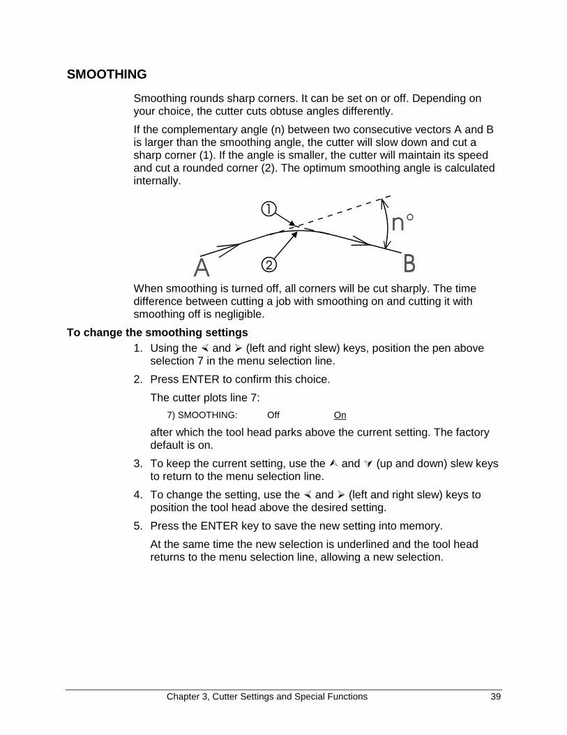
SMOOTHING
Smoothing rounds sharp corners. It can be set on or off. Depending onyour choice, the cutter cuts obtuse angles differently.
If the complementary angle (n) between two consecutive vectors A and Bis larger than the smoothing angle, the cutter will slow down and cut asharp corner (1). If the angle is smaller, the cutter will maintain its speedand cut a rounded corner (2). The optimum smoothing angle is calculatedinternally.
When smoothing is turned off, all corners will be cut sharply. The timedifference between cutting a job with smoothing on and cutting it withsmoothing off is negligible.
To change the smoothing settings1. Using the � and � (left and right slew) keys, position the pen above
selection 7 in the menu selection line.
2. Press ENTER to confirm this choice.
The cutter plots line 7:
7) SMOOTHING: Off On
after which the tool head parks above the current setting. The factorydefault is on.
3. To keep the current setting, use the � and � (up and down) slew keysto return to the menu selection line.
4. To change the setting, use the � and � (left and right slew) keys toposition the tool head above the desired setting.
5. Press the ENTER key to save the new setting into memory.
At the same time the new selection is underlined and the tool headreturns to the menu selection line, allowing a new selection.
40 Chapter 3, Cutter Settings and Special Functions
COMMUNICATION SETTINGS
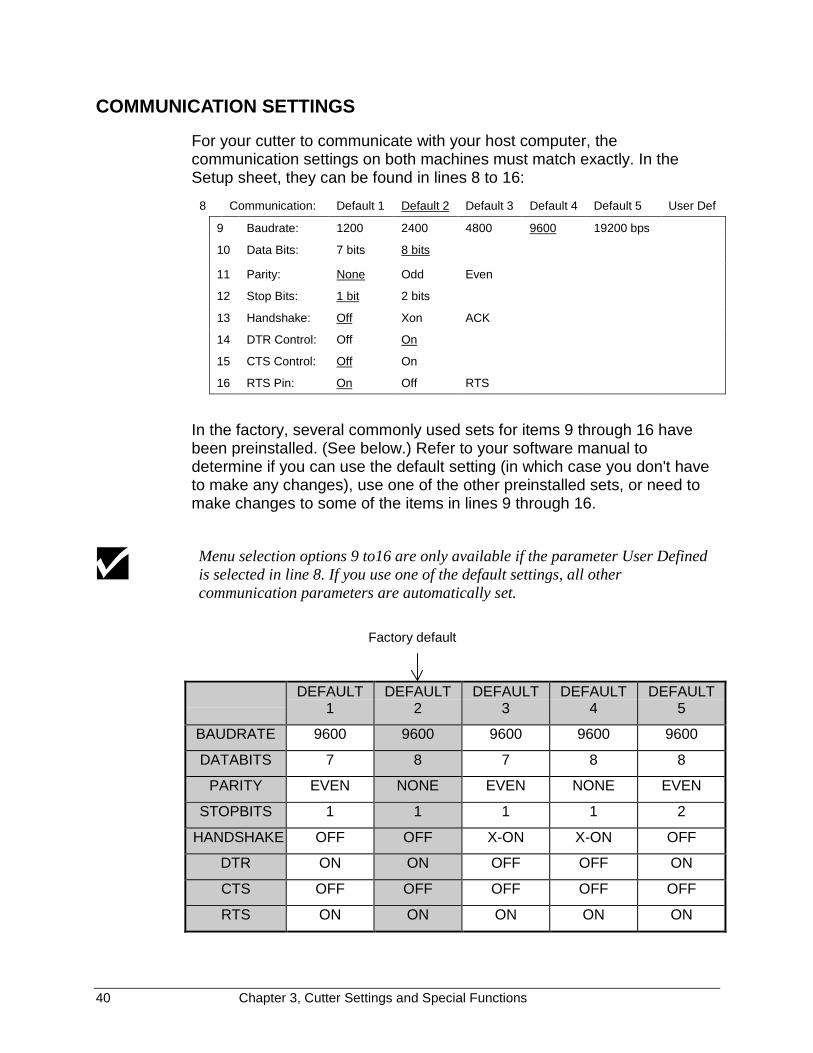
For your cutter to communicate with your host computer, thecommunication settings on both machines must match exactly. In theSetup sheet, they can be found in lines 8 to 16:
8 Communication: Default 1 Default 2 Default 3 Default 4 Default 5 User Def
9 Baudrate: 1200 2400 4800 9600 19200 bps
10 Data Bits: 7 bits 8 bits
11 Parity: None Odd Even
12 Stop Bits: 1 bit 2 bits
13 Handshake: Off Xon ACK
14 DTR Control: Off On
15 CTS Control: Off On
16 RTS Pin: On Off RTS
In the factory, several commonly used sets for items 9 through 16 havebeen preinstalled. (See below.) Refer to your software manual todetermine if you can use the default setting (in which case you don't haveto make any changes), use one of the other preinstalled sets, or need tomake changes to some of the items in lines 9 through 16.
Menu selection options 9 to16 are only available if the parameter User Definedis selected in line 8. If you use one of the default settings, all othercommunication parameters are automatically set.
DEFAULT1
DEFAULT2
DEFAULT3
DEFAULT4
DEFAULT5
BAUDRATE 9600 9600 9600 9600 9600
DATABITS 7 8 7 8 8
PARITY EVEN NONE EVEN NONE EVEN
STOPBITS 1 1 1 1 2
HANDSHAKE OFF OFF X-ON X-ON OFF
DTR ON ON OFF OFF ON
CTS OFF OFF OFF OFF OFF
RTS ON ON ON ON ON
Factory default

Chapter 3, Cutter Settings and Special Functions 41
To change the serial communication settingsIn line 8, choose one of the preinstalled sets or the User Defined selection.If you need to use the User Defined option, alter the settings one by oneuntil they match the desired values.
6. Using the � and � (left and right) slew keys, position the tool headabove the desired selection (between 8 and 16) in the menu selectionline.
7. Press ENTER to confirm this choice.
The cutter plots the corresponding line and the tool head parks abovethe current setting. The factory default setting is default 2.
8. To keep the current setting, use the � and � (up and down) slew keysto return to the menu selection line leaving the original settingunchanged.
9. To change the setting, use the � and � (left and right slew) keys toposition the tool head above the desired setting.
10. Press the ENTER key to save the new setting into memory.
At the same time, the new selection is underlined and the tool headreturns to the menu selection line, allowing a new selection.
42 Chapter 3, Cutter Settings and Special Functions
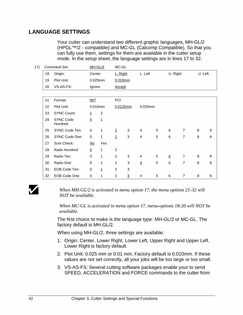
LANGUAGE SETTINGS
Your cutter can understand two different graphic languages, MH-GL/2(HPGL™/2 - compatible) and MC-GL (Calcomp Compatible). So that youcan fully use them, settings for them are available in the cutter setupmode. In the setup sheet, the language settings are in lines 17 to 32.
17) Command Set: MH-GL/2 MC-GL
18 Origin: Center L. Right L. Left U. Right U. Left
19 Plot Unit: 0.025mm 0.010mm
20 VS-AS-FS: Ignore Accept
21 Format: 907 PCI
22 Plot Unit: 0.010mm 0.0125mm 0.025mm
23 SYNC Count: 1 2
24 SYNC CodeHundred:
0 1
25 SYNC Code Ten: 0 1 2 3 4 5 6 7 8 9
26 SYNC Code One: 0 1 2 3 4 5 6 7 8 9
27 Sum Check: No Yes
28 Radix Hundred: 0 1 2
29 Radix Ten: 0 1 2 3 4 5 6 7 8 9
30 Radix One: 0 1 2 3 4 5 6 7 8 9
31 EOB Code Ten: 0 1 2 3
32 EOB Code One: 0 1 2 3 4 5 6 7 8 9
When MH-GL/2 is activated in menu option 17, the menu options 21-32 willNOT be available.
When MC-GL is activated in menu option 17, menu-options 18-20 will NOT beavailable.
The first choice to make is the language type: MH-GL/2 or MC-GL. Thefactory default is MH-GL/2.
When using MH-GL/2, three settings are available:
1. Origin: Center, Lower Right, Lower Left, Upper Right and Upper Left.Lower Right is factory default.
2. Plot Unit: 0.025 mm or 0.01 mm. Factory default is 0.010mm. If thesevalues are not set correctly, all your jobs will be too large or too small.
3. VS-AS-FS: Several cutting software packages enable your to sendSPEED, ACCELERATION and FORCE commands to the cutter from
Chapter 3, Cutter Settings and Special Functions 43
the software. The cutter can be set up to ACCEPT or IGNORE thesecommands.
When using MC-GL, twelve settings are available. Please refer to yoursoftware manual to look for the necessary values if this language isneeded.
To change language settings1. Using the � and � (left and right slew) keys, position the pen above
one of the selections 17 to 32 in the menu selection line.
2. Press ENTER to confirm this choice.
The cutter plots the corresponding line and the tool head parks abovethe current setting.
3. To keep the current setting, use the � and � (up and down slew) keysto return to the menu selection line.
4. To change the setting, use the � and � (left and right slew) keys toposition the tool head above the desired setting.
5. Press the ENTER key to save the new setting into memory.
At the same time, the new selection is underlined and the tool headreturns to the menu selection line, allowing a new selection.
RESET TO FACTORY DEFAULTS
If it is necessary to reset your cutter to its factory default settings, switchthe cutter on while pressing the ORIGIN and the PAGE keys at the sametime.
The LED bar confirms this action. The LEDs display a running light fromthe outside to the inside several times.
Using this function will fully re-initialize your unit. All previously storedlanguage and communication settings will be reset.
In case of doubt, first plot out a setup sheet using the show option of the menuselection line.
It is also possible to set the factory default settings when in "STANDALONEMODE" by pressing the ENTER + MENU up keys. An LED sequence confirmsthe settings to factory default. This procedure is equivalent to pressing theORIGIN and PAGE keys during startup.
44 Chapter 4, Fine Tuning the Cutter
CHAPTER 4FINE TUNING THE CUTTER
The FasTrack cutter provides a step-by-step method to help beginningusers achieve excellent cutting quality. Once you have more experiencewith your cutter, you will be able to fine tune your cutter quickly andaccurately.
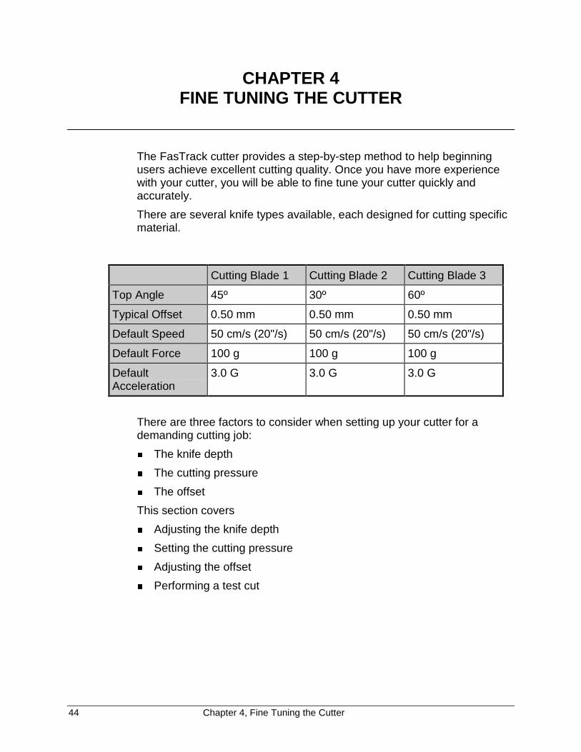
There are several knife types available, each designed for cutting specificmaterial.
Cutting Blade 1 Cutting Blade 2 Cutting Blade 3
Top Angle 45º 30º 60º
Typical Offset 0.50 mm 0.50 mm 0.50 mm
Default Speed 50 cm/s (20"/s) 50 cm/s (20"/s) 50 cm/s (20"/s)
Default Force 100 g 100 g 100 g
DefaultAcceleration
3.0 G 3.0 G 3.0 G
There are three factors to consider when setting up your cutter for ademanding cutting job:
� The knife depth
� The cutting pressure
� The offset
This section covers
� Adjusting the knife depth
� Setting the cutting pressure
� Adjusting the offset
� Performing a test cut
Chapter 4, Fine Tuning the Cutter 45
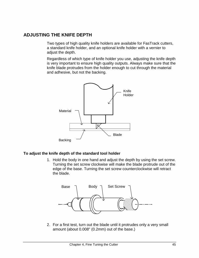
ADJUSTING THE KNIFE DEPTH
Two types of high quality knife holders are available for FasTrack cutters,a standard knife holder, and an optional knife holder with a vernier toadjust the depth.
Regardless of which type of knife holder you use, adjusting the knife depthis very important to ensure high quality outputs. Always make sure that theknife blade protrudes from the holder enough to cut through the materialand adhesive, but not the backing.
KnifeHolder
Blade
Material
Backing
To adjust the knife depth of the standard tool holder
1. Hold the body in one hand and adjust the depth by using the set screw.Turning the set screw clockwise will make the blade protrude out of theedge of the base. Turning the set screw counterclockwise will retractthe blade.
Base Body Set Screw
2. For a first test, turn out the blade until it protrudes only a very smallamount (about 0.008" (0.2mm) out of the base.)
46 Chapter 4, Fine Tuning the Cutter
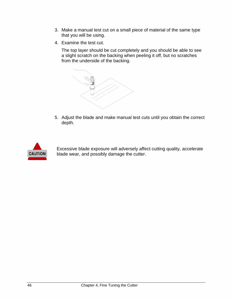
3. Make a manual test cut on a small piece of material of the same typethat you will be using.
4. Examine the test cut.
The top layer should be cut completely and you should be able to seea slight scratch on the backing when peeling it off, but no scratchesfrom the underside of the backing.
5. Adjust the blade and make manual test cuts until you obtain the correctdepth.
Excessive blade exposure will adversely affect cutting quality, accelerateblade wear, and possibly damage the cutter.
Chapter 4, Fine Tuning the Cutter 47
To adjust the knife depth of the optional knife holder
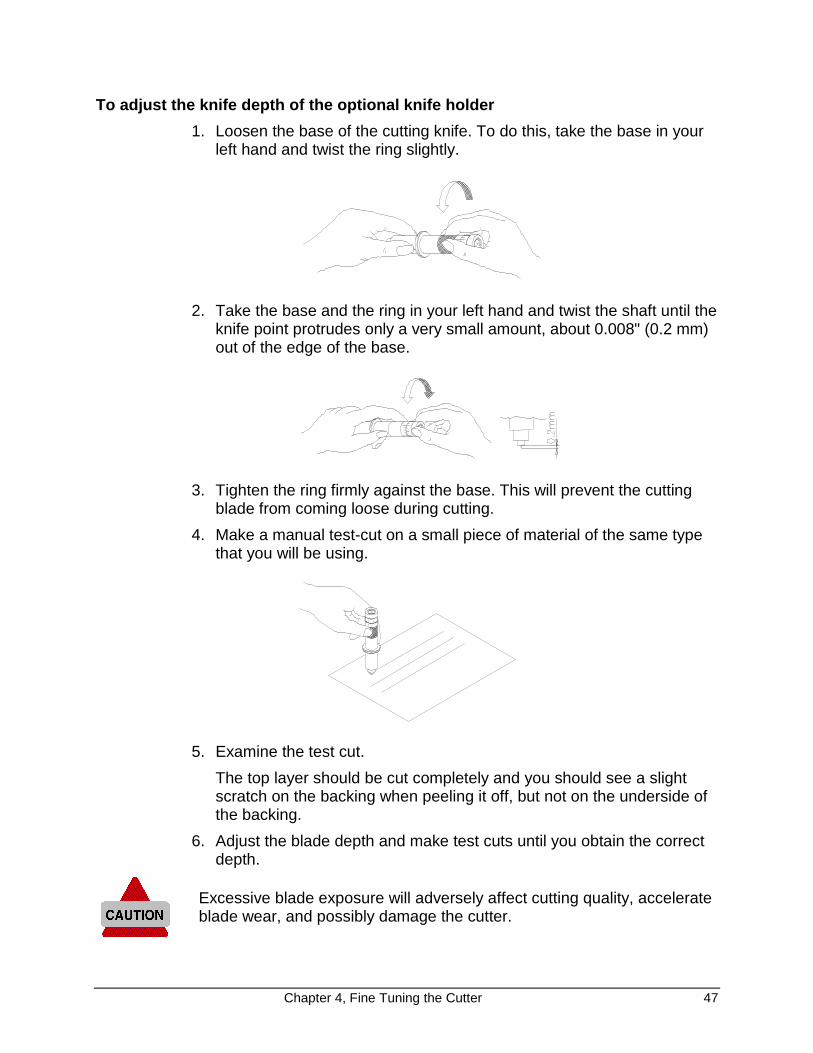
1. Loosen the base of the cutting knife. To do this, take the base in yourleft hand and twist the ring slightly.
2. Take the base and the ring in your left hand and twist the shaft until theknife point protrudes only a very small amount, about 0.008" (0.2 mm)out of the edge of the base.
3. Tighten the ring firmly against the base. This will prevent the cuttingblade from coming loose during cutting.
4. Make a manual test-cut on a small piece of material of the same typethat you will be using.
5. Examine the test cut.
The top layer should be cut completely and you should see a slightscratch on the backing when peeling it off, but not on the underside ofthe backing.
6. Adjust the blade depth and make test cuts until you obtain the correctdepth.
Excessive blade exposure will adversely affect cutting quality, accelerateblade wear, and possibly damage the cutter.
48 Chapter 4, Fine Tuning the Cutter
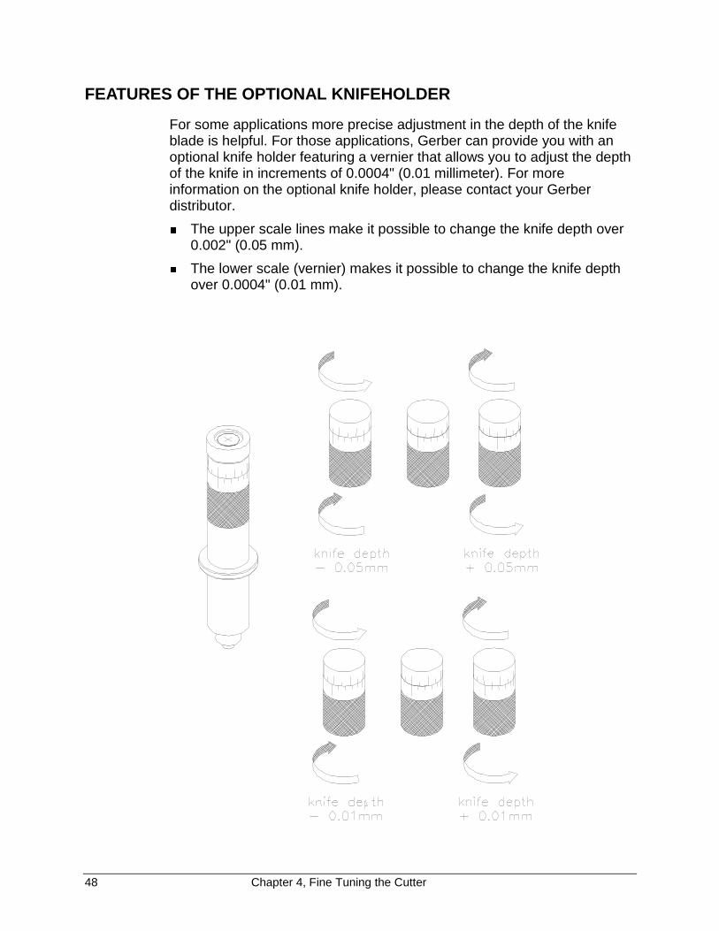
FEATURES OF THE OPTIONAL KNIFEHOLDER
For some applications more precise adjustment in the depth of the knifeblade is helpful. For those applications, Gerber can provide you with anoptional knife holder featuring a vernier that allows you to adjust the depthof the knife in increments of 0.0004" (0.01 millimeter). For moreinformation on the optional knife holder, please contact your Gerberdistributor.
� The upper scale lines make it possible to change the knife depth over0.002" (0.05 mm).
� The lower scale (vernier) makes it possible to change the knife depthover 0.0004" (0.01 mm).
Chapter 4, Fine Tuning the Cutter 49
SETTING THE CUTTING PRESSURE / TEST SQUARES
You are cutting a test square to see if you need to adjust the cuttingpressure as described in Force Selection, page 25, in Chapter 2. Youshould cut your design with the lowest possible pressure that permits easyweeding. Some cast material requires only 15 grams to be cut completelythrough. In that case there is no need to apply 100 grams of pressure. Toomuch pressure can cause a decrease of quality, premature blade wear,and may damage the cutter.
You can cut a small test square using the current force settings as follows:
1. Make sure the cutter is offline. Online LED should be off.
2. Select the FORCE menu by pressing MENU �/� keys until theFORCE LED is on.
3. Using the slew keys, select the position where you want to cut the testsquare.
4. Press the ENTER key for about two seconds.
The cutter will cut a test square.
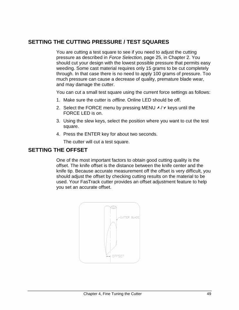
SETTING THE OFFSET
One of the most important factors to obtain good cutting quality is theoffset. The knife offset is the distance between the knife center and theknife tip. Because accurate measurement off the offset is very difficult, youshould adjust the offset by checking cutting results on the material to beused. Your FasTrack cutter provides an offset adjustment feature to helpyou set an accurate offset.
50 Chapter 4, Fine Tuning the Cutter
The diagrams below illustrate the results of incorrectly measured offsets.
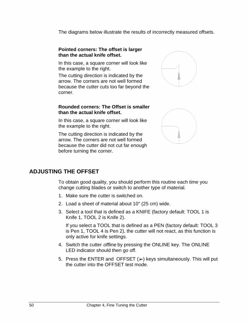
Pointed corners: The offset is largerthan the actual knife offset.
In this case, a square corner will look likethe example to the right.The cutting direction is indicated by thearrow. The corners are not well formedbecause the cutter cuts too far beyond thecorner.
Rounded corners: The Offset is smallerthan the actual knife offset.
In this case, a square corner will look likethe example to the right.
The cutting direction is indicated by thearrow. The corners are not well formedbecause the cutter did not cut far enoughbefore turning the corner.
ADJUSTING THE OFFSET
To obtain good quality, you should perform this routine each time youchange cutting blades or switch to another type of material.
1. Make sure the cutter is switched on.
2. Load a sheet of material about 10" (25 cm) wide.
3. Select a tool that is defined as a KNIFE (factory default: TOOL 1 isKnife 1, TOOL 2 is Knife 2).
If you select a TOOL that is defined as a PEN (factory default: TOOL 3is Pen 1, TOOL 4 is Pen 2), the cutter will not react, as this function isonly active for knife settings.
4. Switch the cutter offline by pressing the ONLINE key. The ONLINELED indicator should then go off.
5. Press the ENTER and OFFSET (➢ ) keys simultaneously. This will putthe cutter into the OFFSET test mode.

Chapter 4, Fine Tuning the Cutter 51
The flashing LED on the LED bar now shows the BASE OFFSETVALUE. Depending on the LED which is flashing, the base value canrange from 0.004" (0.1 mm) to 0.04" (1 mm) as shown below.
� � � � � � � � � �
0.1mm 0.2mm 0.3mm 0.4mm 0.5mm 0.6mm 0.7mm 0.8mm 0.9mm 1mm
6. Using the VALUE +/- keys, adjust the base value to match the offsetvalue of the blade installed in your knife holder. The base offset valueis indicated on the box in which the blades are packed. For the bladesthat come with the cutter, this value is 0.02" (0.5 mm).
7. Press ENTER to confirm the BASE OFFSET value.
The cutter will now be offline, indicated by the ONLINE LED indicatornot lit. This gives you the opportunity to adjust any settings necessary(SPEED, ACCELERATION, FORCE).
8. Press the ONLINE key to switch the cutter online.
The cutter will now generate a set of test patterns, each of them with adifferent offset.
If the base offset is set to 0.02" (0.5 mm), the generated offsets willvary from 0.018" (0.46 mm) up to 0.022" (0.55 mm). When the test cutsare completed, the cutter will advance the material.
9. Check the patterns and determine which of them gives best quality.Look for optimum quality of the corners, closure of the circles, andeasy weeding.
After the machine has drawn the 10 squares to select the best offset,the head is no longer positioned above the most left one. It is nowpositioned above the square belonging to the base offset.
10. You can now use the test cut squares the same way you use the menuselection line to select and enter your choice for blade offset. Using the� and � (left and right slew) keys, move the tool head to the squarewith the best quality. You will see an LED on the LED bar moveaccording to your choice. When the tool head is moved, the material ispartially retracted, but in such a way that the test squares remainvisible.
11. Press ENTER to confirm your choice.
The cutter is now in LOCAL mode.
12. If needed, you can now restart the offset adjustment routine toexperiment with a different force, speed and/or acceleration. (Step 5)
52 Chapter 4, Fine Tuning the Cutter
13. When you are satisfied with the new setting, set the cutter online bypressing the ONLINE key. The ONLINE LED should then come on.
14. Press PAGE to sheet-off the test squares.
If you have 2 knife holders available, you can adjust each one for a differenttype of material and save the settings as KNIFE 1 and KNIFE 2. This will allowyou to switch quickly from one material or job type to the other.
An inaccurate offset setting may cause poor cutting quality and difficultweeding.
If the offset adjustment routine is aborted, the cutter will continue working withthe value it had prior to starting the adjustment routine.
SETTING UP FOR POUNCING (PUNCHING) APPLICATIONS
Your FasTrack cutter can very easily be set up to perform pouncingapplications.
For optimum quality, Gerber recommends using the optionally available softcutting mat for pouncing applications. This cutting mat allows a betterpenetration of the pyramid-shaped pouncing pin.
To perform a pouncing job use one of the following two methods:
Method 1. Pen-Up / Pen-Down sent by cutting software
1. Set the tool settings to a PEN.
2. Set the FORCE to produce acceptable results within the range of 15 to500 grams.
Method 2. Use the incorporated pouncing (punching) capability of the cutter
1. In the cutter set up, set the TOOLKIND of the tool of your choice toPOUNCE
2. Press ENTER and ➢ (slew right).
3. Select the desired gap (distance between punch marks) using theVALUE + /- keys.
10% 20% 30% 40% 50% 60% 70% 80% 90% 100%
1 mm 2 mm 3 mm 4 mm 5 mm 6 mm 7 mm 8 mm 9 mm 10 mm
4. Press ENTER to confirm your choice.
5. The FORCE can be varied in the range of 15 - 500 grams.
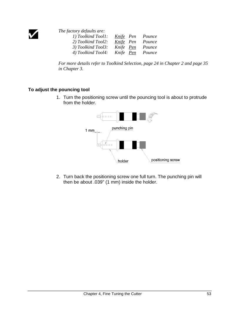
Chapter 4, Fine Tuning the Cutter 53
The factory defaults are:1) Toolkind Tool1: Knife Pen Pounce2) Toolkind Tool2: Knife Pen Pounce3) Toolkind Tool3: Knife Pen Pounce4) Toolkind Tool4: Knife Pen Pounce
For more details refer to Toolkind Selection, page 24 in Chapter 2 and page 35in Chapter 3.
To adjust the pouncing tool
1. Turn the positioning screw until the pouncing tool is about to protrudefrom the holder.
2. Turn back the positioning screw one full turn. The punching pin willthen be about .039" (1 mm) inside the holder.

54 Chapter 4, Fine Tuning the Cutter
PERFORMING A TEST CUT
To check if the cutter is fully functional, there is an integrateddemonstration test cut routine, which can be done without using acomputer. To perform this demo cut:
1. Load some material (cut-sheet or roll) into the cutter.
2. Set TOOLKIND to KNIFE 1 or KNIFE 2, if not already set.
3. Make sure that a knife with well adjusted depth is mounted into the toolhead.
4. If you have not yet adjusted the offset for the current knife and/ormaterial, do so now to obtain perfect quality. (See Adjusting the Offset,page 50, in this chapter).
5. Switch the cutter offline by pressing the ONLINE key. The ONLINELED should go off.
6. Start the test-cut by pressing ENTER and � (up) slew simultaneously.
The test cut is not scaled automatically to fit the material size. In caseof a roll of material, only the width of the roll is taken into account. Thecutter assumes that there is enough material on the roll to perform afull- width test cut. You can determine the size of the test cut byadjusting the position of the pressure rolls.
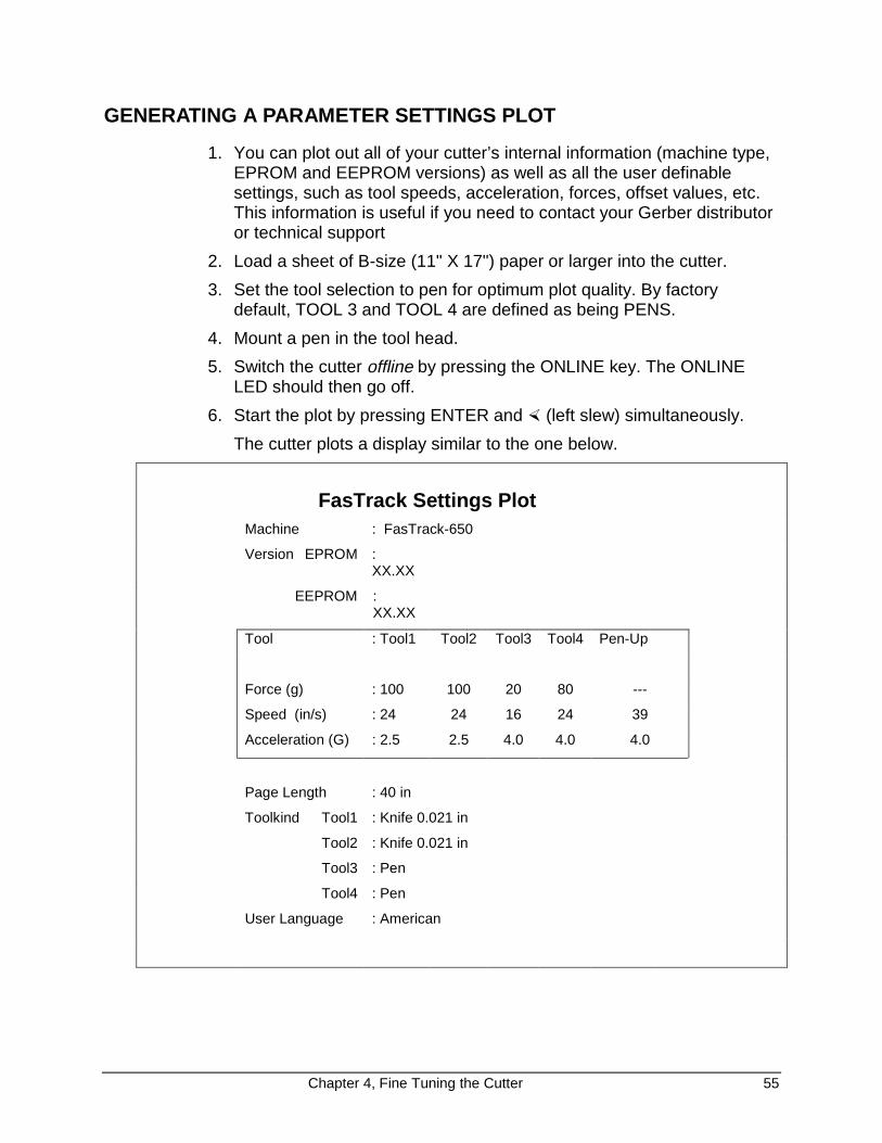
Chapter 4, Fine Tuning the Cutter 55
GENERATING A PARAMETER SETTINGS PLOT
1. You can plot out all of your cutter’s internal information (machine type,EPROM and EEPROM versions) as well as all the user definablesettings, such as tool speeds, acceleration, forces, offset values, etc.This information is useful if you need to contact your Gerber distributoror technical support
2. Load a sheet of B-size (11" X 17") paper or larger into the cutter.
3. Set the tool selection to pen for optimum plot quality. By factorydefault, TOOL 3 and TOOL 4 are defined as being PENS.
4. Mount a pen in the tool head.
5. Switch the cutter offline by pressing the ONLINE key. The ONLINELED should then go off.
6. Start the plot by pressing ENTER and � (left slew) simultaneously.
The cutter plots a display similar to the one below.
FasTrack Settings PlotMachine : FasTrack-650
Version EPROM :XX.XX
EEPROM :XX.XX
Tool : Tool1 Tool2 Tool3 Tool4 Pen-Up
Force (g) : 100 100 20 80 ---
Speed (in/s) : 24 24 16 24 39
Acceleration (G) : 2.5 2.5 4.0 4.0 4.0
Page Length : 40 in
Toolkind Tool1 : Knife 0.021 in
Tool2 : Knife 0.021 in
Tool3 : Pen
Tool4 : Pen
User Language : American
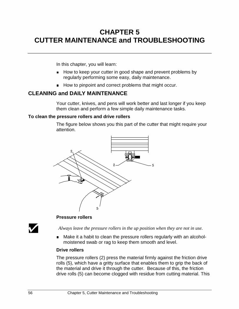
56 Chapter 5, Cutter Maintenance and Troubleshooting
CHAPTER 5CUTTER MAINTENANCE and TROUBLESHOOTING
In this chapter, you will learn:
� How to keep your cutter in good shape and prevent problems byregularly performing some easy, daily maintenance.
� How to pinpoint and correct problems that might occur.
CLEANING and DAILY MAINTENANCE
Your cutter, knives, and pens will work better and last longer if you keepthem clean and perform a few simple daily maintenance tasks.
To clean the pressure rollers and drive rollers
The figure below shows you this part of the cutter that might require yourattention.
Pressure rollers
Always leave the pressure rollers in the up position when they are not in use.
� Make it a habit to clean the pressure rollers regularly with an alcohol-moistened swab or rag to keep them smooth and level.
Drive rollers
The pressure rollers (2) press the material firmly against the friction driverolls (5), which have a gritty surface that enables them to grip the back ofthe material and drive it through the cutter. Because of this, the frictiondrive rolls (5) can become clogged with residue from cutting material. This
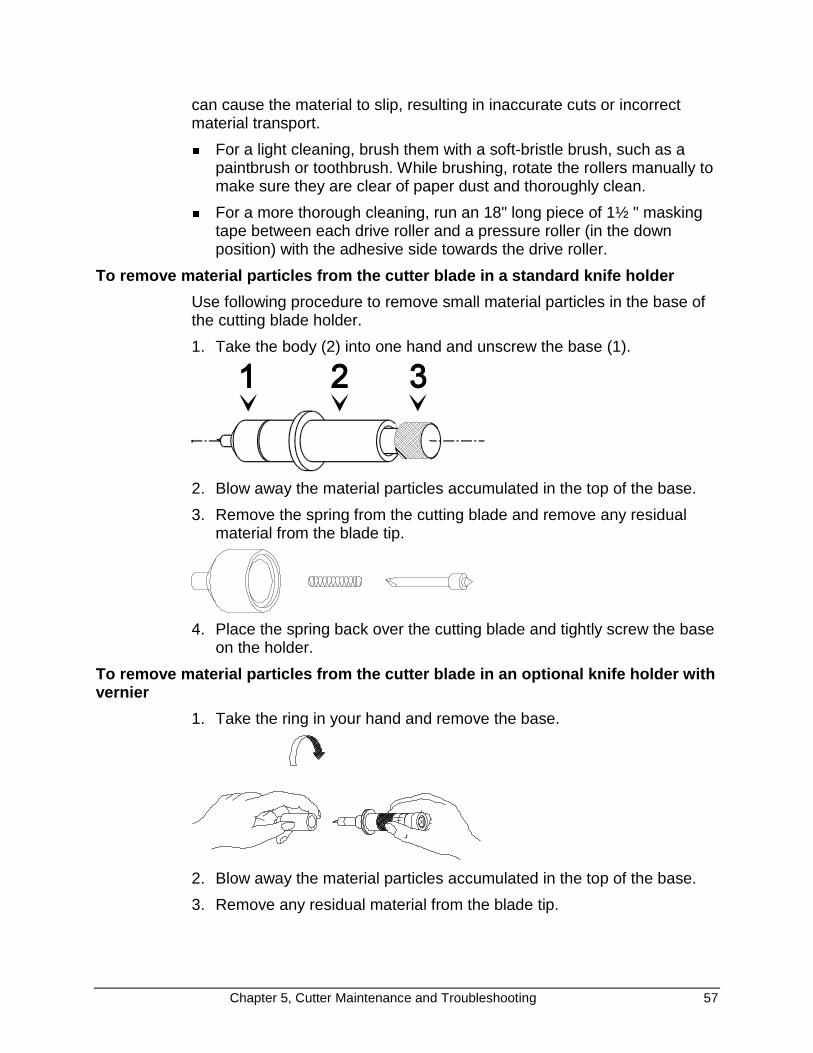
Chapter 5, Cutter Maintenance and Troubleshooting 57
can cause the material to slip, resulting in inaccurate cuts or incorrectmaterial transport.
� For a light cleaning, brush them with a soft-bristle brush, such as apaintbrush or toothbrush. While brushing, rotate the rollers manually tomake sure they are clear of paper dust and thoroughly clean.
� For a more thorough cleaning, run an 18" long piece of 1½ " maskingtape between each drive roller and a pressure roller (in the downposition) with the adhesive side towards the drive roller.
To remove material particles from the cutter blade in a standard knife holder
Use following procedure to remove small material particles in the base ofthe cutting blade holder.
1. Take the body (2) into one hand and unscrew the base (1).
2. Blow away the material particles accumulated in the top of the base.
3. Remove the spring from the cutting blade and remove any residualmaterial from the blade tip.
4. Place the spring back over the cutting blade and tightly screw the baseon the holder.
To remove material particles from the cutter blade in an optional knife holder withvernier
1. Take the ring in your hand and remove the base.
2. Blow away the material particles accumulated in the top of the base.
3. Remove any residual material from the blade tip.
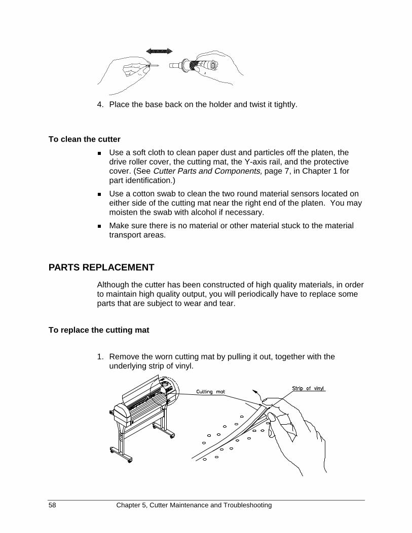
58 Chapter 5, Cutter Maintenance and Troubleshooting
4. Place the base back on the holder and twist it tightly.
To clean the cutter
� Use a soft cloth to clean paper dust and particles off the platen, thedrive roller cover, the cutting mat, the Y-axis rail, and the protectivecover. (See Cutter Parts and Components, page 7, in Chapter 1 forpart identification.)
� Use a cotton swab to clean the two round material sensors located oneither side of the cutting mat near the right end of the platen. You maymoisten the swab with alcohol if necessary.
� Make sure there is no material or other material stuck to the materialtransport areas.
PARTS REPLACEMENT
Although the cutter has been constructed of high quality materials, in orderto maintain high quality output, you will periodically have to replace someparts that are subject to wear and tear.
To replace the cutting mat
1. Remove the worn cutting mat by pulling it out, together with theunderlying strip of vinyl.
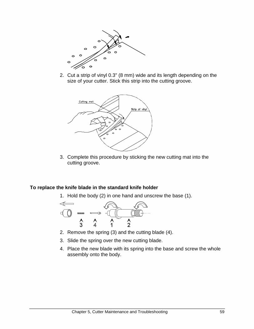
Chapter 5, Cutter Maintenance and Troubleshooting 59
2. Cut a strip of vinyl 0.3" (8 mm) wide and its length depending on thesize of your cutter. Stick this strip into the cutting groove.
3. Complete this procedure by sticking the new cutting mat into thecutting groove.
To replace the knife blade in the standard knife holder
1. Hold the body (2) in one hand and unscrew the base (1).
2. Remove the spring (3) and the cutting blade (4).
3. Slide the spring over the new cutting blade.
4. Place the new blade with its spring into the base and screw the wholeassembly onto the body.
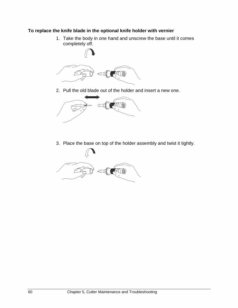
60 Chapter 5, Cutter Maintenance and Troubleshooting
To replace the knife blade in the optional knife holder with vernier
1. Take the body in one hand and unscrew the base until it comescompletely off.
2. Pull the old blade out of the holder and insert a new one.
3. Place the base on top of the holder assembly and twist it tightly.

Chapter 5, Cutter Maintenance and Troubleshooting 61
To replace the auto-sheet-off knife
When you frequently use the auto-sheet-off utility, it is a good practice toregularly clean the knife and to replace it when it starts to wear.
1. Unscrew the ring (1) that secures the auto-sheet-off knife.
2. Take off the ring (1) and take the knife assembly (2) out of the toolhead.
3. Make sure to leave the spring (3) located in the tool head in place.
4. Clean the sheet-off knife, removing any material residues that might beadhering to the blade. If the blade is worn, use a new knife assembly.
5. Place a new (or the cleaned) knife assembly (2) into the tool head. Theknife assembly has a flat side. Make sure that it is correctly orientedwith the flat side to the right. See the figure below. You can easilycheck this by trying to push the knife downward manually until ittouches the cutting mat. This should be possible without any trouble.
6. Screw the ring (2) back on the tool head, over the knife assembly, tosecure the knife into place.
7. Check again if the knife can be moved smoothly and if it returns into itsoriginal “up” position when you release it.

62 Chapter 5, Cutter Maintenance and Troubleshooting
TROUBLESHOOTING
This section gives a summary of problems that might occur during day-to-day use of your cutter and some hints how to determine the cause of theproblem.
1. Power switch is turned on, but the cutter does not operate.
� Is the cutter’s protective cover closed?
� Is the power cable connected to the cutter?
� Is the cutter connected to a power outlet with the specified voltage?
2. Material is loaded, but the cutter does not operate.
� Is the cutter’s protective cover closed?
� Is the material hold lever lowered?
� Is the material properly loaded?
� Are the paper sensors clean?
3. Data is being sent from the computer, but the cutter does not react.
� Is there a proper interface cable connected?
� Is the cutter in online mode?
� Do the interface settings on the host computer match those set onthe cutter? (See Communications Settings, page 40, in Chapter 3.)
4. Data is sent from the computer but errors occur on the cutter’s side.
� Are the output settings correct on the host computer and in thecutting software?
� Do the interface settings on the host computer match those set onthe cutter? (See Communications Settings, page 40, in Chapter 3.)
� Does the command mode on the host computer match thecommand mode on the cutter? (See Language Settings, page 42,in Chapter 3.)
5. Some parts of the design are not well cut.
� Check whether the knife tip is clogged with material residues.
� Examine the knife blade with a magnifier to see if the tip isdamaged or broken.
� Perform the offset adjustment routine to check cutting quality.(See Adjusting the Offset, page 49, in Chapter 4.)
� Perform the internal test cut and check its quality. (See Performinga Test Cut page 54, in Chapter 4.)

Chapter 5, Cutter Maintenance and Troubleshooting 63
To check the communication settings
4. Communication problems are the most frequent errors. Therefore, wehave included a step-by-step procedure for you to use to reset thecomputer's serial communication settings to match the cutter's factorydefault settings and run a test cut.
7. Boot-up your computer.
8. Switch on the cutter.
9. After the start-up routine is finished, install a knife or pen in the toolhead, select the proper tool and load a sheet of material which is atleast 4.75" X 4.75" (12 x 12 cm).
10. Make sure the cutter shuffles the material and verify that the cutter isonline.
11. On the host computer go to the MS-DOS prompt (c:\>).
If another environment (for example: Windows) is automatically loadedafter booting up, quit this application before continuing.
12. Verify to which of the host computer’s communication ports your cutteris connected (COM1, COM2).
13. If your computer and cutter are linked with a serial interface (COM1 orCOM2), type the following command.
MODE COM1: 96,n,8,1,p (If your cutter is connected to COM1)
or
MODE COM2: 96,n,8,1,p (If your cutter is connected to COM2)
then press <ENTER>
The command above will change your computer’s serial communication settingsto match the cutter’s factory default communication settings. These settings are:9600 BAUD, NONE parity, 8 data-bits, 1 stop bit.
14. Using any text editor, create a file called TEST.PLT with the followingcontents
(To start the DOS editor you can type: edit TEST.PLT <ENTER>):
IN;SP1;PA0,0;PD0,4000,4000,4000,4000,0,0,0;PU2000,2000;CI2000;SP0;

64 Chapter 5, Cutter Maintenance and Troubleshooting
15. Save this file onto a floppy diskette or your hard-drive.
16. Exit the text editor and return to the MS-DOS prompt.
17. Make sure you are in the directory where the file is located.
18. Type following command:
copy TEST.PLT COM1 (If your cutter is connected to COM1)
copy TEST.PLT COM2 (If your cutter is connected to COM2)
19. Press ENTER.
The file you have created will now be sent to the cutter, causing it tocut/draw a square 3.94” by 3.94” (10 cm by 10 cm) and a circle with aradius of 1.97” (5 cm).
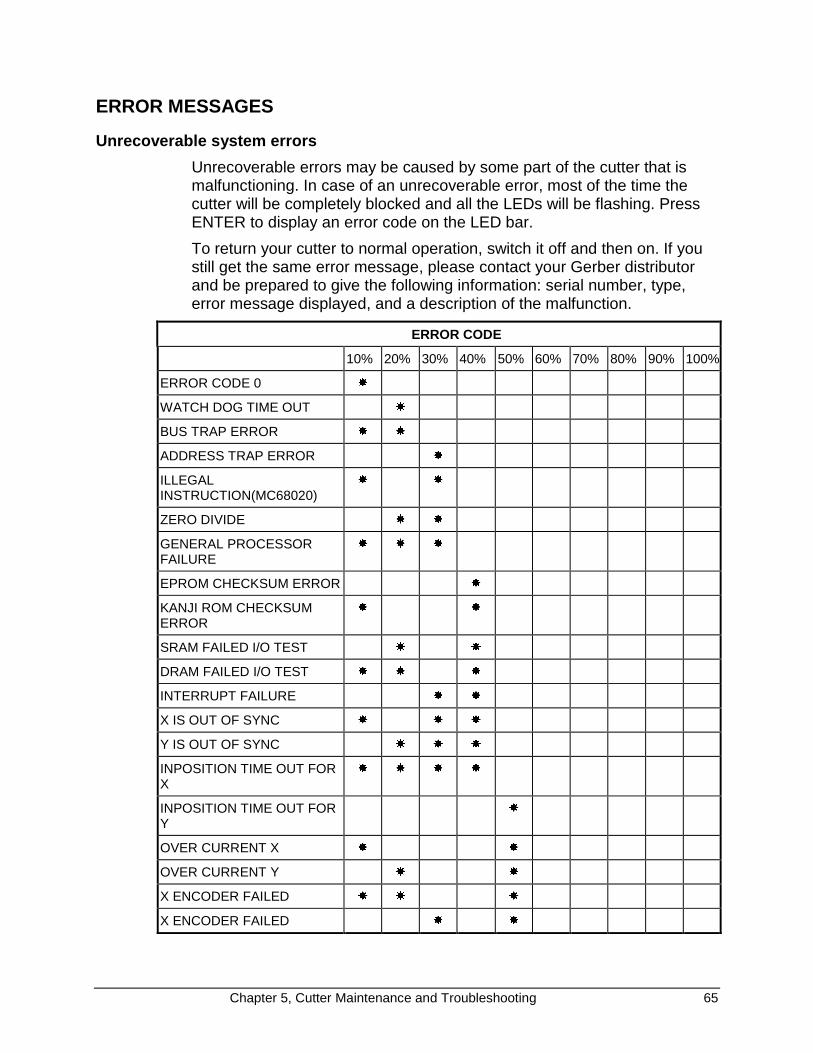
Chapter 5, Cutter Maintenance and Troubleshooting 65
ERROR MESSAGES
Unrecoverable system errors
Unrecoverable errors may be caused by some part of the cutter that ismalfunctioning. In case of an unrecoverable error, most of the time thecutter will be completely blocked and all the LEDs will be flashing. PressENTER to display an error code on the LED bar.
To return your cutter to normal operation, switch it off and then on. If youstill get the same error message, please contact your Gerber distributorand be prepared to give the following information: serial number, type,error message displayed, and a description of the malfunction.
ERROR CODE
10% 20% 30% 40% 50% 60% 70% 80% 90% 100%
ERROR CODE 0 �
WATCH DOG TIME OUT �
BUS TRAP ERROR � �
ADDRESS TRAP ERROR �
ILLEGALINSTRUCTION(MC68020)
� �
ZERO DIVIDE � �
GENERAL PROCESSORFAILURE
� � �
EPROM CHECKSUM ERROR �
KANJI ROM CHECKSUMERROR
� �
SRAM FAILED I/O TEST � �
DRAM FAILED I/O TEST � � �
INTERRUPT FAILURE � �
X IS OUT OF SYNC � � �
Y IS OUT OF SYNC � � �
INPOSITION TIME OUT FORX
� � � �
INPOSITION TIME OUT FORY
�
OVER CURRENT X � �
OVER CURRENT Y � �
X ENCODER FAILED � � �
X ENCODER FAILED � �
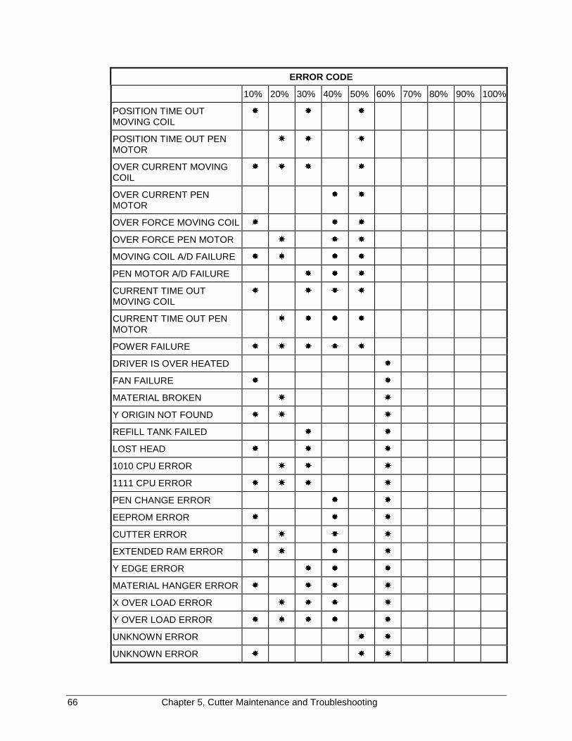
66 Chapter 5, Cutter Maintenance and Troubleshooting
ERROR CODE
10% 20% 30% 40% 50% 60% 70% 80% 90% 100%
POSITION TIME OUTMOVING COIL
� � �
POSITION TIME OUT PENMOTOR
� � �
OVER CURRENT MOVINGCOIL
� � � �
OVER CURRENT PENMOTOR
� �
OVER FORCE MOVING COIL � � �
OVER FORCE PEN MOTOR � � �
MOVING COIL A/D FAILURE � � � �
PEN MOTOR A/D FAILURE � � �
CURRENT TIME OUTMOVING COIL
� � � �
CURRENT TIME OUT PENMOTOR
� � � �
POWER FAILURE � � � � �
DRIVER IS OVER HEATED �
FAN FAILURE � �
MATERIAL BROKEN � �
Y ORIGIN NOT FOUND � � �
REFILL TANK FAILED � �
LOST HEAD � � �
1010 CPU ERROR � � �
1111 CPU ERROR � � � �
PEN CHANGE ERROR � �
EEPROM ERROR � � �
CUTTER ERROR � � �
EXTENDED RAM ERROR � � � �
Y EDGE ERROR � � �
MATERIAL HANGER ERROR � � � �
X OVER LOAD ERROR � � � �
Y OVER LOAD ERROR � � � � �
UNKNOWN ERROR � �
UNKNOWN ERROR � � �

Chapter 5, Cutter Maintenance and Troubleshooting 67
ERROR CODE
10% 20% 30% 40% 50% 60% 70% 80% 90% 100%
UNKNOWN ERROR � � �
INTERLOCK ERROR � � � �
MOVING COIL ENCODERFAILURE
� � �
PEN MOTOR ENCODERFAILURE
� � � �
DRIVER FAILURE � � � �
ILLEGAL MAIN BOARDREVISION
� � � � �
ILLEGAL PANEL BOARDREVISION
� � �
MAINBOARD TYPE ERROR � � � �
ILLEGAL OPTIONAL I/FBOARD REVISION
� � � �
UNKNOWN OPTIONAL I/FBOARD
� � � � �
ILLEGAL MECHANICALREVISION
� � � �
MECHANICAL TYPE ERROR � � � � �
XY CONNECT FAILED � � � � �
PROM TYPE MISMATCH �
EEPROM IS NOTRESPONDING
� �
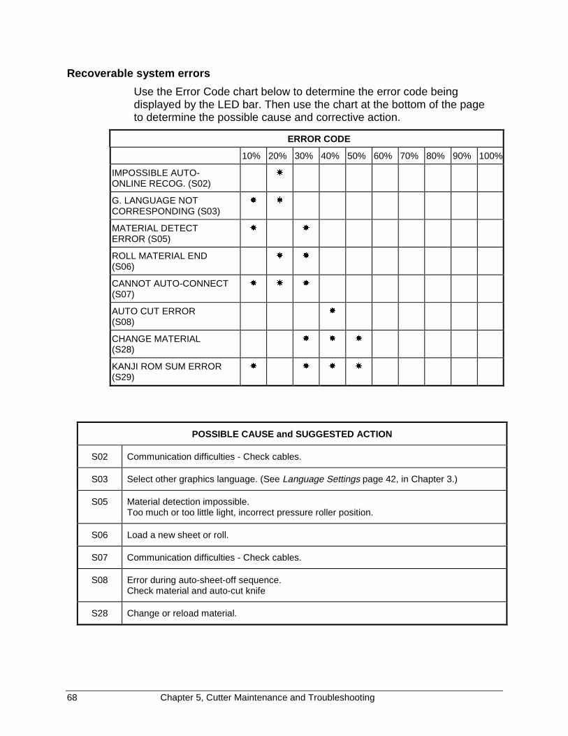
68 Chapter 5, Cutter Maintenance and Troubleshooting
Recoverable system errors
Use the Error Code chart below to determine the error code beingdisplayed by the LED bar. Then use the chart at the bottom of the pageto determine the possible cause and corrective action.
ERROR CODE
10% 20% 30% 40% 50% 60% 70% 80% 90% 100%
IMPOSSIBLE AUTO-ONLINE RECOG. (S02)
�
G. LANGUAGE NOTCORRESPONDING (S03)
� �
MATERIAL DETECTERROR (S05)
� �
ROLL MATERIAL END(S06)
� �
CANNOT AUTO-CONNECT(S07)
� � �
AUTO CUT ERROR(S08)
�
CHANGE MATERIAL(S28)
� � �
KANJI ROM SUM ERROR(S29)
� � � �
POSSIBLE CAUSE and SUGGESTED ACTION
S02 Communication difficulties - Check cables.
S03 Select other graphics language. (See Language Settings page 42, in Chapter 3.)
S05 Material detection impossible.Too much or too little light, incorrect pressure roller position.
S06 Load a new sheet or roll.
S07 Communication difficulties - Check cables.
S08 Error during auto-sheet-off sequence.Check material and auto-cut knife
S28 Change or reload material.

Chapter 5, Cutter Maintenance and Troubleshooting 69
Communication errors
Communication errors are caused by a problem in the communicationbetween the cutter and the host computer. They can be caused by errorsrelated to the communication settings, errors due to a defectivehandshake, or command format errors in the ESCAPE sequences.
Use the Error Code chart below to determine the error code beingdisplayed by the LED bar. Then use the chart on the next page todetermine the possible cause and corrective action.
ERROR CODE
10% 20% 30% 40% 50% 60% 70% 80% 90% 100%
ERROR ONLINE FRAMEC01
� �
ERROR ONLINE OVERRUNC02
� �
ERROR ONLINE PARITYC03
� � �
ERROR BIAS VALUEC04
� �
ERROR SUM CHECKC05
� � �
ERROR DATA BLOCKC06
� � �
FEW PARAMETER ESCC07
� � � �
FEW PARAMETER ESCC08
� � �
COMMUNICATION BUSYC09
� � �
UNDEFINED ESCC10
� � � �
ILLEGAL ESCC11
� � �
ERROR VALUE ESCC12
� � � �
MANY PARAMETERS ESCC13
� � � �
COMMUNICATION ERRORC14
� � � � �
BUFFER OVERFLOWC15
� �
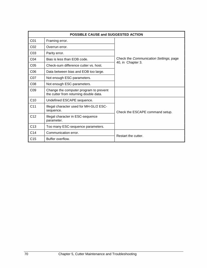
70 Chapter 5, Cutter Maintenance and Troubleshooting
POSSIBLE CAUSE and SUGGESTED ACTION
C01 Framing error.
C02 Overrun error.
C03 Parity error.
C04 Bias is less than EOB code.
C05 Check-sum difference cutter vs. host.
C06 Data between bias and EOB too large.
C07 Not enough ESC-parameters.
C08 Not enough ESC-parameters.
Check the Communication Settings, page40, in Chapter 3.
C09 Change the computer program to preventthe cutter from returning double data.
C10 Undefined ESCAPE sequence.
C11 Illegal character used for MH-GL/2 ESC-sequence.
C12 Illegal character in ESC-sequenceparameter.
C13 Too many ESC-sequence parameters.
Check the ESCAPE command setup.
C14 Communication error.
C15 Buffer overflow.Restart the cutter.
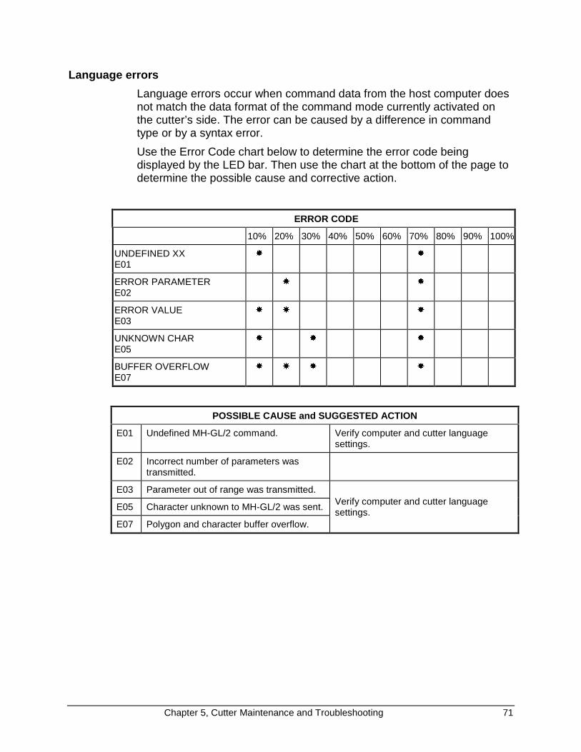
Chapter 5, Cutter Maintenance and Troubleshooting 71
Language errors
Language errors occur when command data from the host computer doesnot match the data format of the command mode currently activated onthe cutter’s side. The error can be caused by a difference in commandtype or by a syntax error.
Use the Error Code chart below to determine the error code beingdisplayed by the LED bar. Then use the chart at the bottom of the page todetermine the possible cause and corrective action.
ERROR CODE
10% 20% 30% 40% 50% 60% 70% 80% 90% 100%
UNDEFINED XXE01
� �
ERROR PARAMETERE02
� �
ERROR VALUEE03
� � �
UNKNOWN CHARE05
� � �
BUFFER OVERFLOWE07
� � � �
POSSIBLE CAUSE and SUGGESTED ACTION
E01 Undefined MH-GL/2 command. Verify computer and cutter languagesettings.
E02 Incorrect number of parameters wastransmitted.
E03 Parameter out of range was transmitted.
E05 Character unknown to MH-GL/2 was sent.
E07 Polygon and character buffer overflow.
Verify computer and cutter languagesettings.
72 Chapter 6, Cutter Options and Accessories
CHAPTER 6CUTTER OPTIONS and ACCESSORIES,
OPTIONS and ACCESSORIES FOR FasTrack CUTTERS
Cutting Mat (Set - 3 pcs)
Standard knife holder without depth indication including one blade angle45°, offset 0.5 mm and one spring
High-Quality, Long-Life Blades (Tungsten Carbide) for Standard KnifeHolder
Blades 30° (set of two - including one spring)
Blades 45° (set of two - including one spring)
Blades 60° (set of two - including one spring)
Sheeting-Off Knife Assembly (one/pc)
Knife holder with Depth Indication including one blade, angle 45°, offset0.5 mm
High-Quality, Long-Life Blades (Tungsten Carbide) for Knife Holder withVernier Graduation, offset 0.5 mm
Cutting Knife Blades 30° (Set of Two)
Cutting Knife Blades 45° (Set of Two)
Cutting Knife Blades 60° (Set of Two)
Conveyor Flanges (for all models)
Conveyor Flange Core 3" (Set of Two)
Punching tool assembly including punch pin
Spare punch pin assembly
Cutting mat for punching applications (Set - 3 pcs)
Basket for Media Collection
All FasTrack cutters include cutter stand (except for FT-650 desktopmodel), set of conveyor rolls with small plastic rings to prevent roll shifting,operation manual in English, set of 3 knives (45° for vinyl), one knifeholder, two marking pens, serial cable, power cable, spare cutting and 1Mb buffer.

Chapter 6, Cutter Options and Accessories 73
This page intentionally left blank.
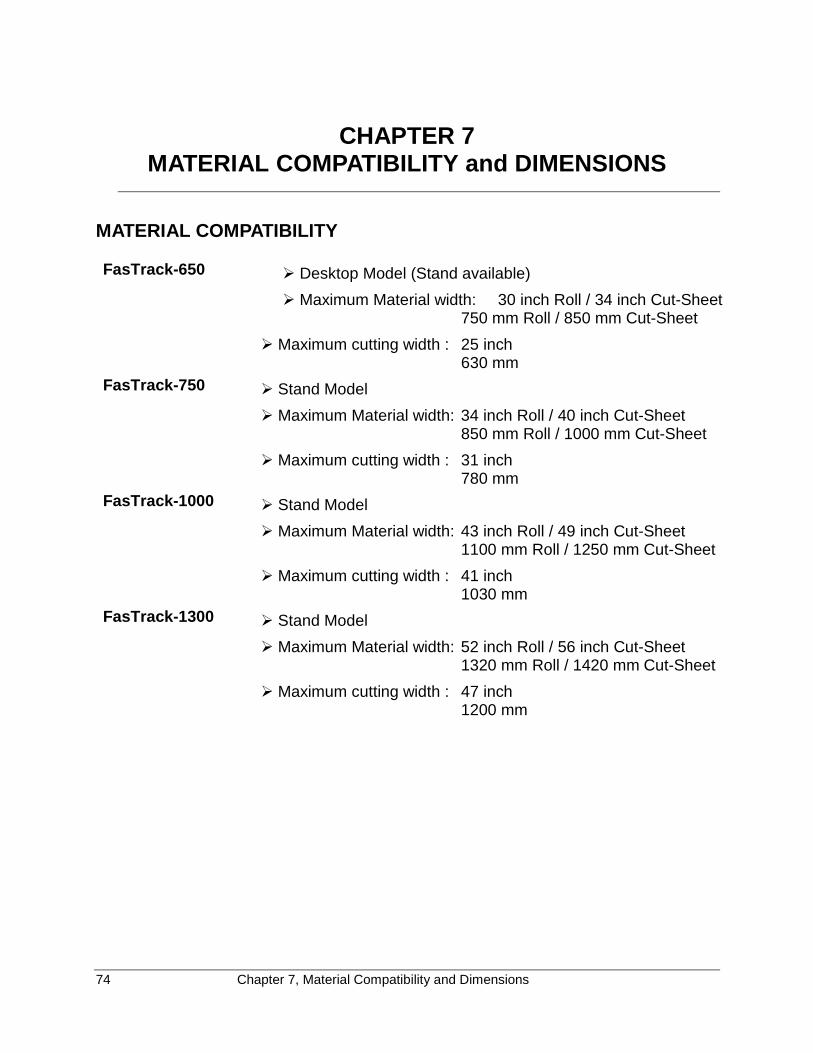
74 Chapter 7, Material Compatibility and Dimensions
CHAPTER 7MATERIAL COMPATIBILITY and DIMENSIONS
MATERIAL COMPATIBILITY
FasTrack-650 � Desktop Model (Stand available)
� Maximum Material width: 30 inch Roll / 34 inch Cut-Sheet 750 mm Roll / 850 mm Cut-Sheet
� Maximum cutting width : 25 inch630 mm
FasTrack-750 � Stand Model
� Maximum Material width: 34 inch Roll / 40 inch Cut-Sheet850 mm Roll / 1000 mm Cut-Sheet
� Maximum cutting width : 31 inch780 mm
FasTrack-1000 � Stand Model
� Maximum Material width: 43 inch Roll / 49 inch Cut-Sheet1100 mm Roll / 1250 mm Cut-Sheet
� Maximum cutting width : 41 inch1030 mm
FasTrack-1300 � Stand Model
� Maximum Material width: 52 inch Roll / 56 inch Cut-Sheet1320 mm Roll / 1420 mm Cut-Sheet
� Maximum cutting width : 47 inch1200 mm

Chapter 7, Material Compatibility and Dimensions 75
PHYSICAL DIMENSIONS FasTrack Series
Imperial dimensions in inches and pounds (*Desk-Top model)
FasTrack-650 FasTrack-750 FasTrack-1000 FasTrack-1300
Length 47 53 63 70
Width 21 (DT*) / 26 26 26 26
Height 13 (DT*) / 46 46 46 46
Weight 80 82 93 99
Metric dimensions in millimeters and kilograms (*Desk-Top model)
FasTrack-650 FasTrack-750 FasTrack-1000 FasTrack-1300
Length 1205 1355 1605 1775
Width 535 (DT*) / 670 670 670 670
Height 335 (DT*) / 1175 1175 1175 1175
Weight 35 kg 37 kg 42 kg 45 kg
INDEX
A
acceleration selection ...................................... 27ambient conditions ............................................. 4attention captions............................................... 1attentions and cautions...................................... 1auto sheet-off
knife replacement ........................................ 61auto-sheet-off................................................... 17
B
bladecleaning, optional knife holder..................... 57cleaning, standard knife holder ................... 57replacement, optional knife holder .............. 60replacement, standard knife holder ............. 59
C
carriage cover .................................................... 8cautions, attentions and..................................... 1clean cutter ...................................................... 58communication settings ................................... 40
to check ....................................................... 63connecting the cutter........................................ 10connecting the power cable ............................. 11control panel .................................................. 8, 9
understanding.............................................. 18conveyor rolls............................................... 8, 15customer support ............................................... 2cut-sheet material
loading ......................................................... 13cutter box
contents ......................................................... 6cutting groove .................................................. 59cutting mat ................................................... 8, 52
replacement................................................. 58cutting pressure
setting .......................................................... 49
D
daily maintenance............................................ 56drive rollers ........................................................ 8
E
ENTER key .................................................. 9, 20environment
cutter.............................................................. 4errors
communications........................................... 69
language...................................................... 71recoverable.................................................. 68unrecoverable.............................................. 65
even tensionroll material.................................................. 16
F
FasTrack 1000pressure rollers...................................... 14, 16
fine tuning ........................................................ 44flanges ............................................................. 16force
ranges ......................................................... 26selection ...................................................... 25
G
gapdefined......................................................... 52
general settings ............................................... 35guiding flanges .................................................. 8
H
HPGL/2 ............................................................ 42humidity ............................................................. 4
I
indicators, LED .................................................. 9indicators, ONLINE LED.................................... 9installing tools .................................................. 12
K
keysENTER .................................................... 9, 20MENU selection....................................... 9, 21ONLINE ................................................... 9, 18ORIGIN.................................................... 9, 19PAGE ...................................................... 9, 20slew ............................................................. 19slew ............................................................... 9Value +/- ........................................................ 9
knife depthadjusting ...................................................... 45adjusting, optional knife holder.................... 47adjusting, standard tool holder .................... 45
knife holdersinstalling ...................................................... 12types............................................................ 45
knife types........................................................ 44
L
languagecomputer graphics ....................................... 42user, changing ............................................. 32
language settingschange......................................................... 43
LED .................................................................... 9bar............................................................ 9, 18indicators ....................................................... 9ONLINE indicator........................................... 9
loadingcut-sheet material ........................................ 13roll material .................................................. 15
M
maintenance and troubleshooting.................... 56marker lines ..................................................... 16material hold lever.............................................. 8material loading
cut-sheet ...................................................... 13roll ................................................................ 15
material sensors............................................... 58MC-GL ............................................................. 42menu mode operation...................................... 32MENU selection keys....................................... 21MENU selection keys......................................... 9menu selection line .......................................... 33MH-GL/2 .......................................................... 42mode, operating ............................................... 18mounting bracket
tool head...................................................... 12
O
offline mode ...........................................9, 19, 21offset
base value ................................................... 51defined......................................................... 49setting .......................................................... 49
offset valuebase............................................................. 51
ONLINE key ................................................. 9, 18ONLINE mode............................................19, 21optional knifeholder
features........................................................ 48ORIGIN key............................................9, 19, 43
P
PAGEcommand...............................................28, 36sheet-off....................................................... 17
PAGE key ..............................................9, 20, 43relocate origin point ..................................... 36
page length ...................................................... 27exceeded ..................................................... 29
to set............................................................ 28page mode....................................................... 36
set................................................................ 37Page Mode 0 ................................................... 36Page Mode 1 ................................................... 36Page Mode 2 ................................................... 36parameter settings plot
generate ...................................................... 55parameter values
imperial........................................................ 30metric........................................................... 31
parametersmodifiable .................................................... 21
parts and components ....................................... 7parts replacement............................................ 58pens
installing ...................................................... 12PG
PAGE command ......................................... 36Pgn
PAGE command ......................................... 36physical dimensions ........................................ 74platen and drive roller cover .............................. 8plot unit ............................................................ 42pouncing
setup............................................................ 52tool adjusting ............................................... 53
power cableconnecting ................................................... 11
power connector ................................................ 8power supply...................................................... 4power switch...................................................... 8pressure rollers...................................... 8, 14, 16
R
replotfunction.......................................................... 9multiplication factor ..................................... 38multiplication factor ..................................... 20start ............................................................. 20
replot factor...................................................... 38reset and clear................................................. 29RESET key ...................................................... 29reset to factory defaults ................................... 43roll material
loading......................................................... 15page length.................................................. 27
roll support system ............................................ 8RS-232C...................................................... 8, 10
S
serial interface connector .................................. 8settings plot...................................................... 55
example....................................................... 71SETUP key ...................................................... 32
setup sheet ................................................32, 33language...................................................... 32
sheet-off ........................................................... 36force............................................................. 17
sheet-off / page mode...................................... 36set ................................................................ 37
sheet-off knifeorientation.................................................... 61
shuffle length.................................................... 16slew keys ..................................................... 9, 19smoothing ........................................................ 39
angle ............................................................ 39speed selection ................................................ 27square corners
on cut sheet ................................................. 14stand .................................................................. 6straighten edge of vinyl sheet .......................... 17support, customer .............................................. 2
T
temperature........................................................ 4test cut ............................................................. 54
machine function ......................................... 54manual ......................................................... 47
test patterns ..................................................... 51test square ....................................................... 49TEST.PLT ........................................................ 63
thumbscrew ..................................................... 12tool collar ......................................................... 12tool head............................................................ 8tool selection.................................................... 23toolkind
selection ................................................ 24, 35toolkind selection ............................................. 35tool-up status ................................................... 23troubleshooting ................................................ 62
U
unpackiing and setting up.................................. 5
V
VALUE +/- keys ................................................. 9vernier.............................................................. 48vinyl
strip under cutting mat................................. 59VS-AS-FS ........................................................ 42
X
X-axis................................................................. 8
Y
Y-axis................................................................. 8

���������������� ���
���� ������
Please take a moment to complete this questionnaire and mail it to Gerber Scientific Products or fax to860-290-5568. We are working hard to produce documentation that will meet your needs. We value your comments.
Name:__________________________________ Phone: ______________________________
Address:_____________________________________________________________________
1 2 3 4 5
1. How many years of experience doyou have with personal computers?
none ( ) ( ) ( ) ( ) ( ) over 5 yrsexperience
2. How often do you refer to themanual?
never ( ) ( ) ( ) ( ) ( ) frequently
3. Was the manual easy to use? difficult ( ) ( ) ( ) ( ) ( ) easy
4. Did you learn what you needed toknow?
no ( ) ( ) ( ) ( ) ( ) yes
5. Was the manual well organized? poorlyorganized
( ) ( ) ( ) ( ) ( ) very well organized
6. Was the manual clearly written? not clear ( ) ( ) ( ) ( ) ( ) very clear
7. Were there enough illustrations? notenough
( ) ( ) ( ) ( ) ( ) enough
8. Did the illustrations support theprocedures?
no ( ) ( ) ( ) ( ) ( ) yes
9. What is your overall rating of themanual?
poor ( ) ( ) ( ) ( ) ( ) excellent
10. How often do you refer to OnlineHelp?
never ( ) ( ) ( ) ( ) ( ) frequently
11. What is your overall rating of OnlineHelp?
poor ( ) ( ) ( ) ( ) ( ) excellent
Comments:_____________________________________________________________________
______________________________________________________________________________

01 2156#)'
0'%'55#4;
+( /#+.'&
+0 6*'
70+6'& 56#6'5
�������������� �(+456 %.#55 2'4/+6 01� ��� /#0%*'56'4� %6
2156#)' 9+.. $' 2#+& $; #&&4'55''
#660� 6'%*0+%#. 27$.+%#6+105
)GTDGT 5EKGPVKHKE 2TQFWEVU� +PE�
��� $CVUQP &TKXG
/CPEJGUVGT� %6 ���������� 75#

P71802A Rev A
������������������� ��������
������������� ��������������������������������������