facility study document - oati weboasis tep winchester substation is one of the two remote...
TRANSCRIPT

FACILITY STUDY DOCUMENT
PREPARED BY:
Q19

POWER ENGINEERS, INC.
PHX 128-120 127695 (08/28/2013) GG PAGE i REV. 7
FACILITY STUDY
PREPARED FOR: TUCSON ELECTRIC POWER
PROJECT CONTACTS:
JIM TAYLOR [email protected]
520-745-3441
ANA BUSTAMANTE [email protected]
520-917-8733
REVISION HISTORY
DATE REVISED BY REVISION
12/20/2012 J. NODURFT 0
1/17/2013 J. NODURFT 1
4/1/2013 J. NODURFT 2
4/10/2013 J. NODURFT 3
4/19/2013 J. NODURFT 4
5/6/2013 J. NODURFT 5
8/23/2013 J. NODURFT 6
8/28/2013 J. NODURFT 7

POWER ENGINEERS, INC.
PHX 128-120 127695 (08/28/2013) GG PAGE ii REV. 7
TABLE OF CONTENTS
1.0 INTRODUCTION ........................................................................................................................ 1
SWITCHYARD ....................................................................................................................... 1 WINCHESTER SUBSTATION ................................................................................................................. 1 GREENLEE/PHIL YOUNG SUBSTATION ............................................................................................... 1
TRANSMISSION LINE ............................................................................................... 1
2.0 FORWARD ................................................................................................................................... 2
3.0 DISCLAIMER .............................................................................................................................. 2
4.0 SCOPE OF WORK ...................................................................................................................... 3
4.1 TRANSMISSION .............................................................................................................................. 4 4.2 SITE SURVEY ................................................................................................................................. 4 4.3 GEOTECHNICAL FIELD INVESTIGATIONS AND ENGINEERING ....................................................... 4 4.4 345 SWITCHYARD SITE DESIGN ............................................................................... 4 4.5 WINCHESTER SUBSTATION SITE ................................................................................................... 6 4.6 GREENLEE/PHIL YOUNG SUBSTATION SITE ................................................................................. 7 4.7 TRANSMISSION SYSTEM ............................................................................................................... 7
5.0 ESTIMATES OF PROBABLE COST AND CONSTRUCTION TIME ESTIMATES ........ 8
5.1 ESTIMATES OF PROBABLE COST ................................................................................................... 8 5.2 CONSTRUCTION TIME ESTIMATES ................................................................................................ 9
6.0 REFERENCES ........................................................................................................................... 10
ATTACHMENT A: ONE LINE DIAGRAM ― 345 KV SWITCHYARD (INITIAL) .............................................................................................................................................................. 11
ATTACHMENT B: ONE LINE DIAGRAM ― 345 KV SWITCHYARD (ULTIMATE) ...................................................................................................................................... 12
ATTACHMENT C: ONE LINE DIAGRAM ― 345 KV SWITCHYARD PROTECTION (INITIAL) ................................................................................................................ 13
ATTACHMENT D: ONE LINE DIAGRAM ― 345 KV SWITCHYARD PROTECTION (ULTIMATE) SHEET 1 - 3 ................................................................................... 14
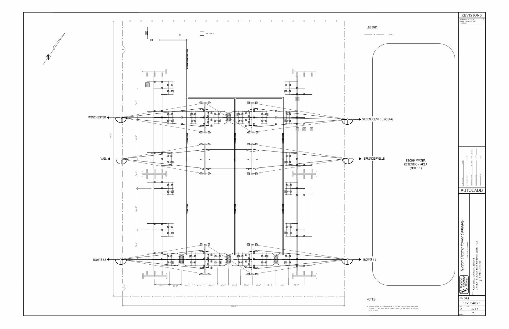
ATTACHMENT E: GENERAL ARRANGEMENT ― 345 KV SWITCHYARD STRAIN BUS (INITIAL) ................................................................................................................... 15
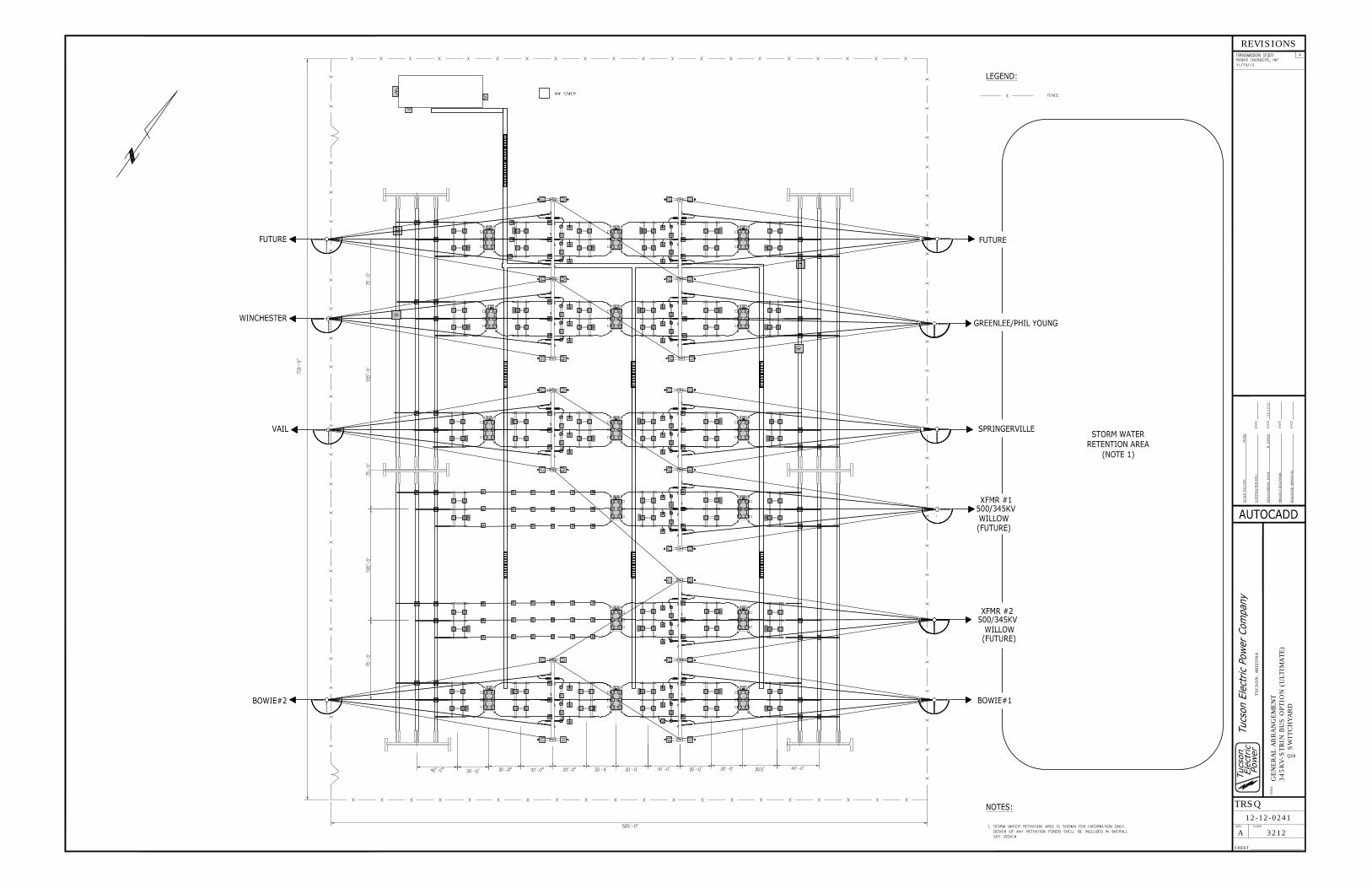
ATTACHMENT F: GENERAL ARRANGEMENT ― 345 KV SWITCHYARD STRAIN BUS (ULTIMATE) ............................................................................................................. 16
ATTACHMENT G: BLOCK DIAGRAM ― 345 KV SWITCHYARD COMMUNICATION BLOCK DIAGRAM ..................................................................................... 17
ATTACHMENT H: BLOCK DIAGRAM ― 345 KV SWITCHYARD AUTOMATION BLOCK DIAGRAM ............................................................................................. 18
Q19
Q19
Q19
Q19
Q19
Q19
Q19
Q19
Q19
Q19
Q19

POWER ENGINEERS, INC.
PHX 128-120 127695 (08/28/2013) GG PAGE 1 REV. 7
1.0 INTRODUCTION
Switchyard
The Switchyard site is located about one (1) mile east of Highway 191 and approximately eight (8) miles north of Interstate 10. Switchyard will be the
interconnection point into the Tucson Electric Power (TEP) transmission system. will be a newly established 345 kV switchyard which will serve as the point of interconnection (POI) to the existing TEP Winchester – Greenlee/Phil Young Transmission Line. The establishment of Switchyard will require modifications to each of the remote substations connected on the existing Winchester – Greenlee/Phil Young 345 kV Transmission Line. The Switchyard initial build-out will be a four (4) breaker ‘ring’ bus arrangement laid out for an eighteen (18) breaker, breaker-and-a-half (BAAH) ultimate arrangement. Two line terminals in the initial configuration will connect to the
Switchyard and the remaining two will connect to TEP’s Winchester and Greenlee/Phil Young substations.
Winchester Substation
The TEP Winchester Substation is one of the two remote substations. TEP has determined that the primary relay channel communication between Switchyard and Winchester Substation will be via microwave as a primary system and Power Line Carrier (PLC) acting as the back-up communications system. In order to meet this requirement, the existing Greenlee/Phil Young line terminal at Winchester must be modified. Other modifications to the Winchester Substation to facilitate the establishment of Switchyard include the reprogramming of the protective digital relays, modification of the microwave communication system, and updating equipment nameplates.
Greenlee/Phil Young Substation
The TEP Greenlee/Phil Young Substation is the other of the two remote substations to the Switchyard. TEP has determined that the primary relay channel communication
between Switchyard and Greenlee/Phil Young Substation will be via microwave as a primary system and Power Line Carrier (PLC) acting as the back-up communications system. In order to meet this requirement, the existing Winchester line terminal at Greenlee/Phil Young Substation must be modified. Other modifications to the Greenlee/Phil Young Substation to facilitate the establishment of Switchyard include the reprogramming of the protective digital relays, modifications of the microwave communication system, and updating equipment nameplates.
Transmission Line
This double circuit 345 kV transmission line will originate at Switchyard located approximately two (2) miles north of the town of Bowie, Arizona. The line will traverse generally north and west before entering Switchyard. The 345 kV transmission line from Power Station to Switchyard will be approximately fifteen (15) miles long. The construction will be self supporting tubular steel
Q19
Q19
Q19
Q19
Q19
Q19
Q19Q19
Q19
Q19
Q19
Q19
Q19
Q19Q19
Q19
Q19
Q19
POWER ENGINEERS, INC.
PHX 128-120 127695 (08/28/2013) GG PAGE 2 REV. 7
poles, double circuit configuration, and double bundled conductor with separate overhead and optical ground wires.
2.0 FORWARD
This estimate has been prepared with +/- 20% accuracy. A 20% contingency has been added to the estimate which is to be applied before any adder is considered. All assumptions are clearly defined within this document and should be duly noted. Many costs included in this report will vary with market conditions and the final design. While this document reflects budgetary estimates, it is important to note that labor and material costs continue to rise. Additionally, the prices of both equipment and construction labor fluctuate. This report contains current costs, but these costs are subject to change based on market conditions and final design. The cost amounts reimbursed by
will be the actual expenses incurred in the completion of work as defined herein (including overheads). Repayment details will be documented and finalized in the Large Generator Interconnect Agreement (LGIA).
3.0 DISCLAIMER
The developer will be required to meet all FERC, NERC, and other governing agency requirements. Estimates, forecasts, projections, and schedules relating to costs, final design, quantities, and pricing (including but not limited to, property costs, construction, operation or maintenance costs, and/or energy or commodity demand and pricing), are opinions based upon experience, qualifications, and judgment. The Retail Service Provider has no control over the weather, cost, availability of labor, materials and equipment, labor productivity, energy or commodity pricing, demand or usage, population demographics, market conditions, regulatory environment, change in technology, and other economic or political factors effecting such estimates or projections. The Retail Service Provider acknowledges that actual results may vary significantly from the representations and opinions herein. Nothing herein will be construed as a guarantee or warranty (actual or implied) that rates, demand, pricing, costs, performance schedules, quantities, technology, or any other related items will not vary from opinions contained in this report. All costs included in this estimate are subject to change if the final design, project performance, or requirements change from that shown on the preliminary data provided by This estimate does not include any land, easements, access roads, land grading or preparation, surveying, storm water permitting and handling, custom design structures, extraordinary circumstances (high resistance ground, difficult terrain, etc.), special protection schemes, or permitting costs. Any additional time spent and/or costs incurred will be the responsibility of the developer. “Network Upgrades” are intended to refer to all facilities required to be upgraded to mitigate impacts of the Project that are on the utility side of Point of Interconnection.
Q19
Q19
POWER ENGINEERS, INC.
PHX 128-120 127695 (08/28/2013) GG PAGE 3 REV. 7
Typically the cost for capacity, if any, above that required by the Project that is part of a Network Upgrade is reimbursed over time. This amount is negotiated by the parties as required by the LGIA.
4.0 SCOPE OF WORK In summary, this Facilities Study:
• Specifies and estimates the cost of the equipment, engineering, procurement and construction work (including overhead transmission lines) needed to implement the interconnection facility.
• Identifies the electrical switching configuration of the equipment, including, without limitation, circuit breakers, disconnect switches, protection, station security, communications facilities and other station equipment.
• Identifies an estimate of the time required to complete the construction and installation of such facilities.
The following attachments are also included in the scope of work:
• Attachment A: One Line Diagram ― 345 kV Switchyard (Initial) • Attachment B: One Line Diagram ― 345 kV Switchyard (Ultimate) • Attachment C: One Line Diagram ― 345 kV Switchyard Protection (Initial) • Attachment D: One Line Diagram ― 345 kV Switchyard Protection (Ultimate)
Sheets 1 – 3 of 3 • Attachment E: General Arrangement ― 345 kV Switchyard Strain Bus (Initial) • Attachment F: General Arrangement ― 345 kV Switchyard Strain Bus
(Ultimate) • Attachment G: Block Diagram ― 345 kV Switchyard Communication Block
Diagram • Attachment H: Block Diagram ― 345 kV Switchyard Automation Block
Diagram
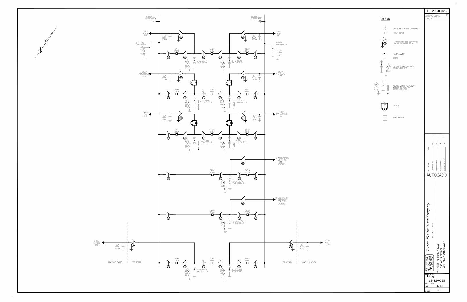
The scope of work includes the design, procurement, construction, and commissioning of a new 345 kV Switchyard facility and the necessary transmission upgrades needed to interconnect the new switchyard. The switchyard facility will consist of six (6) bays with the initial build incorporating a four (4) breaker ring bus configuration in bays two (2) and six (6). Bay Two (2) will include one (1) 345 kV circuit breaker which will act as the landing point for TEPs 345 kV Winchester-Greenlee/Phil Young transmission line. Bay Six (6) will include three (3) 345 kV circuit breakers configured in a BAAH scheme bringing in two (2) generation feeders from Power Station. Bay Three (3) will bring the TEP Springerville-Vail transmission line into the switchyard but will only pass through the switchyard at this time. Bays one, four and five (1, 4 and 5) will remain open for the initial development of Switchyard, but will be utilized in the future. Attachments E and F show the Initial and Ultimate General Arrangements respectively. TEPs Springerville-Vail and Winchester-Greenlee/Phil Young 345 kV transmission lines currently run inside an easement approximately seven hundred feet (700’) north of the proposed Switchyard site. The existing easement provides space for an
Q19
Q19Q19Q19Q19
Q19Q19
Q19
Q19
Q19
Q19
Q19
POWER ENGINEERS, INC.
PHX 128-120 127695 (08/28/2013) GG PAGE 4 REV. 7
additional 345 kV transmission line to accommodate for future growth. A new transmission line easement will be required between TEPs existing transmission easement and the new Switchyard. TEP will reroute the existing 345 kV transmission lines through Switchyard requiring the addition of new 345 kV steel support structures inside the new easement. The new easement will also need to be adequate to accommodate the additional future 345 kV transmission line which will be incorporated into Bay One (1) in the ultimate design. A System Impact Study (SIS) has been performed and was completed on July 11, 2012 to determine what impacts the addition of the 500 MW Power Station project would have on TEP’s 345 kV transmission system. Any additional generation above the 500 MW net output of generation would need to be studied to evaluate any additional impacts it may have on TEP and surrounding transmission systems. To ensure that NERC Standards and WECC System Performance Regional Business Practices are not violated, is required to mitigate any violation that the additional generation causes and participate to the level of project contribution to any existing violations. The SIS found that N-2/N-1-1 contingencies would result in transmission facility overloads. Mitigation was proposed for system improvements such as upgrading overloaded transmission lines and installing capacitors for voltage support or a Special Protection Scheme (SPS) would mitigate the issues found with the initial 500 MW of
generation.
4.1 Transmission
This project will incorporate TEPs Winchester-Greenlee/Phil Young and Springerville-Vail 345 kV transmission lines into the new Switchyard. This project will also accommodate for future development, leaving room for an additional 345 kV line running parallel to the existing two TEP lines being brought into Switchyard.
4.2 Site Survey
The Project shall secure services from a TEP approved survey company to perform site and access road surveys. Survey data will be used in grading design, soil cut-and-fill calculations and structure positioning.
4.3 Geotechnical Field Investigations and Engineering
A geotechnical investigation for the Switchyard site will be completed by a TEP approved geotechnical firm. The results of this report will be evaluated to establish the design basis for foundation and electrical grounding design.
4.4 345 kV Switchyard Site Design
will be responsible for all site preparation work, grading and drainage design at the Switchyard site with TEP approval as appropriate to meet TEP standards.
345 kV Switchyard Site – Site Preparation, Grading and Drainage Design
Q19
Q19
Q19
Q19
Q19
Q19Q19
Q19
Q19
Q19
Q19
Q19
Q19
POWER ENGINEERS, INC.
PHX 128-120 127695 (08/28/2013) GG PAGE 5 REV. 7
345 kV Switchyard Site – Civil/Structural Design All station foundations, footings, etc. shall be designed according to TEP standards. A complete ground-grid per the most recent ANSI/IEEE STD 80 using 4/0 copper will be installed. A 30x80 foot control house will be installed to contain the metering, protection, control devices, and all ancillary equipment necessary to facilitate switchyard operation. A 10x20 foot section of this building will be walled off with a dedicated outside entrance and no entrance from inside the building for non-TEP protection, communication, and automation and control equipment. Conduit will be routed between the control building and equipment via cable trench and Under Ground (UG) PVC conduits with Rigid Galvanized Steel (RGS) above ground. The transition hub at ground level will be sealed with concrete.
All equipment will be rated at 345 kV nominal with 3000A continuous and 40kA short circuit ratings. Ratings are based upon System Impact Study values and Power Station second power block having identical ratings to the first.
345 kV Switchyard Site – Electrical Design
The bus design for this new substation will use ACSR strain bus configured as a four breaker, four terminal ‘ring’ bus with an ultimate build-out of a 18 breaker, 12 terminal BAAH layout. The bays will be rated for 3000A and the main busses will be rated for 4000A. Primary station service will utilize a single phase 333kV Bus Power Potential Transformer on each main bus (A and B). Back-up station service power will be provided by a 80kW propane stand by generator. DC service will be supplied by a 63 cell, 125VDC, 720Ah battery bank. The microwave communication system will have its own 24 cell, 48VDC, 280Ah battery bank.
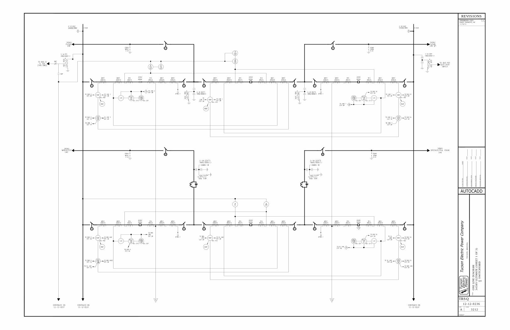
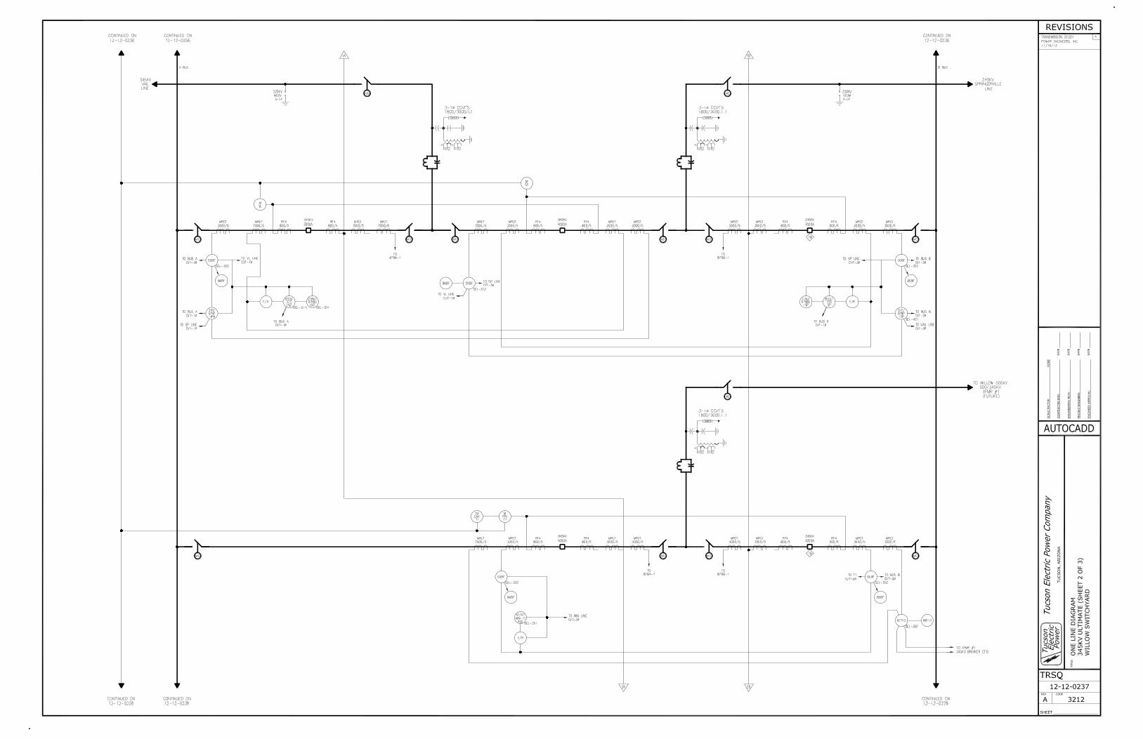
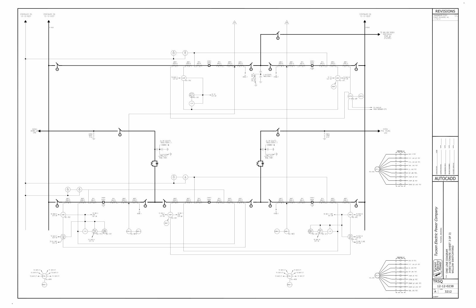
Switchyard will be protected against lightning strikes via static masts and static wires. Lightning protection will be based on the ‘Rolling Sphere’ method. To allow for re-establishment of the ‘ring’ during a line outage line disconnect switches will be installed on each terminal. All of the terminal line disconnects will have grounding switches on the line side of the disconnect switch to provide visual grounding verification and enhance personnel safety. 345 kV Switchyard Site – Protection, Metering, Automation and CommunicationsProtective relaying at Switchyard will be performed using high speed microprocessor relays and coordinated with the remote end relays at Winchester and Greenlee/Phil Young Substations and Plant Switchyard. Distance relaying and line differential relaying will incorporate the SEL-421, SEL-321 and SEL-311L respectively. Each circuit breaker will be protected by over current and breaker failure relaying using the SEL-352. Future BAAH bus protection will be performed using a current differential scheme.
Q19
Q19
Q19
Q19
Q19
Q19Q19

POWER ENGINEERS, INC.
PHX 128-120 127695 (08/28/2013) GG PAGE 6 REV. 7
Primary relay channel communication between Switchyard and the Winchester and Greenlee/Phil Young Substations will be via microwave, while secondary relay channel communications will incorporate Power Line Carrier (PLC). Preliminary design provided by the developer shows both primary and secondary relay channel communication between
Switchyard and Plant Switchyard will be implemented using two fiber optic cables in an Optical Ground Wire (OPGW). Microwave towers and ancillary microwave equipment will be installed within thirty (30’) feet of switchyard control building. The communications systems between Switchyard and the Plant Switchyard, Winchester Substation and Greenlee/Phil Young Substation will be in place to allow for the SPS option mentioned in the SIS to be implemented. Should decide to implement the SPS option opposed to the system improvement option, the SPS will be owned, operated, and maintained by the Customer. The SIS study assumed the loss of power output from the project would be made up by the Navajo generator swing bus. Meeting incremental power and/or reserve requirements are assumed to be the responsibility of the project. Metering accuracy bushing current transformers and bus potential transformers will supply the TEP ION revenue meters with 345 kV TEP transmission system power usage quantities.
will also locate primary and secondary revenue meters within Switchyard for verification. 345 kV Switchyard Site – Site Security
Switchyard security will be designed to meet TEP security specifications and North American Electric Reliability Corporation (NERC) Critical Infrastructure Protection (CIP) standards; as required.
4.5 Winchester Substation Site
345 kV Winchester Substation – Civil/Structural UpgradesConduit will be routed between control building and equipment via cable trench and Under Ground (UG) PVC conduits with Rigid Galvanized Steel (RGS) above ground. The transition hub at ground level will be sealed with concrete.
Any modifications and/or additions to the existing ground-grid located at the line terminal will be made per most recent ANSI/IEEE STD 80 using 4/0 copper and will tie to new equipment and existing grid.
Existing high speed microprocessor distance and line differential protective relays will be re-programmed to coordinate with the corresponding relays at Switchyard.
345 kV Winchester Substation – Protection, Metering, Automation and Communications Upgrades
Communication facilities will exchange protection, metering, control and communication signals between Winchester Substation and Switchyard. The primary relay channel communication will be achieved by using microwave facilities. The secondary relay channel and the remainder of communication functions will be via PLC. The existing Winchester line terminal B and C phase conductor will be upgraded with a Coupling Capacitor Voltage Transformer (CCVT) with carrier accessories and a line trap.
Q19
Q19
Q19
Q19
Q19
Q19
Q19
Q19
Q19Q19
Q19
Q19
Q19
POWER ENGINEERS, INC.
PHX 128-120 127695 (08/28/2013) GG PAGE 7 REV. 7
Nameplates will be replaced on protective relaying panel and equipment as necessary to alter line destination to Switchyard from Greenlee/Phil Young Substation.
4.6 Greenlee/Phil Young Substation Site
345 kV Greenlee/Phil Young Substation – Civil/Structural UpgradesConduit will be routed between control building and equipment via cable trench and Under Ground (UG) PVC conduits with Rigid Galvanized Steel (RGS) above ground. The transition hub at ground level will be sealed with concrete.
Any modifications and/or additions to the existing ground-grid located at the line terminal will be made per most recent ANSI/IEEE STD 80 using 4/0 copper and will tie to new equipment and existing grid.
Line Protection: Existing high speed microprocessor distance and line differential protective relays will be re-programmed to coordinate with the corresponding relays at Switchyard.
345 kV Greenlee/Phil Young – Protection, Metering, Automation and Communications Upgrades
Communication facilities will exchange protection, metering, control and communication signals between Greenlee/Phil Young Substation and Switchyard. The primary relay channel communication will be achieved by using microwave facilities. The secondary relay channel and the remainder of communication functions will be via PLC. The existing Greenlee/Phil Young line terminal B and C phase conductor will be upgraded with a Coupling Capacitor Voltage Transformer (CCVT) with carrier accessories and a line trap. Nameplates will be replaced on protective relaying panel and equipment as necessary to alter line destination to Switchyard from Winchester Substation.
4.7 Transmission System
The following Transmission Upgrades are required to connect Switchyard to TEPs 345 kV transmission system and meet mitigation impact requirements:
• The breaking of TEPs Winchester to Greenlee/Phil Young 345 kV transmission line.
• The rerouting of TEPs Springerville to Vail 345 kV transmission line. • The addition of eight (8) 90° deadend free-standing monopoles. • The addition of three (3) twin bundled 954 kcmil ACSR (Cardinal) and two static
wires between the new 90° deadend free-standing monopoles connecting existing TEP 345 kV transmission lines with Switchyard.
Q19
Q19
Q19
Q19
Q19
Q19
Q19
POWER ENGINEERS, INC.
PHX 128-120 127695 (08/28/2013) GG PAGE 8 REV. 7
5.0 ESTIMATES OF PROBABLE COST AND CONSTRUCTION TIME ESTIMATES 5.1 Estimates of Probable Cost
Project dollar amounts shown in this section are in 2013 US dollars. The cost of the Plant Switchyard equipment and construction is not included in this study. The
cost of the 345 kV double-circuit transmission line between Plant Switchyard and Switchyard are not included in this study. All costs include materials, labor, and
overheads.
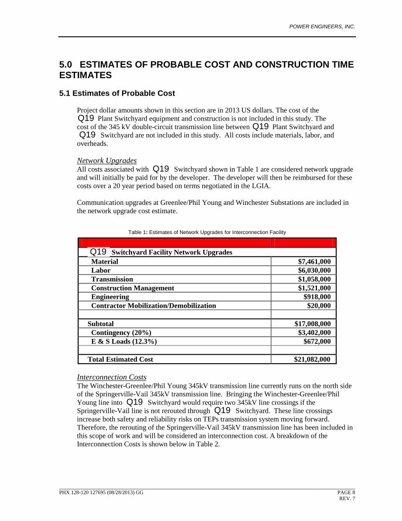
All costs associated with Switchyard shown in Table 1 are considered network upgrade and will initially be paid for by the developer. The developer will then be reimbursed for these costs over a 20 year period based on terms negotiated in the LGIA.
Network Upgrades
Communication upgrades at Greenlee/Phil Young and Winchester Substations are included in the network upgrade cost estimate.
Table 1: Estimates of Network Upgrades for Interconnection Facility
The Winchester-Greenlee/Phil Young 345kV transmission line currently runs on the north side of the Springerville-Vail 345kV transmission line. Bringing the Winchester-Greenlee/Phil Young line into Switchyard would require two 345kV line crossings if the Springerville-Vail line is not rerouted through Switchyard. These line crossings increase both safety and reliability risks on TEPs transmission system moving forward. Therefore, the rerouting of the Springerville-Vail 345kV transmission line has been included in this scope of work and will be considered an interconnection cost. A breakdown of the Interconnection Costs is shown below in Table 2.
Interconnection Costs
Element Cost Switchyard Facility Network Upgrades
Material $7,461,000 Labor $6,030,000 Transmission $1,058,000 Construction Management $1,521,000 Engineering $918,000 Contractor Mobilization/Demobilization $20,000 Subtotal $17,008,000 Contingency (20%) $3,402,000 E & S Loads (12.3%) $672,000 Total Estimated Cost $21,082,000
Q19Q19
Q19
Q19
Q19
Q19Q19

POWER ENGINEERS, INC.
PHX 128-120 127695 (08/28/2013) GG PAGE 9 REV. 7
Table 2: Estimates of Interconnection Costs for Interconnection Facility
5.2 Construction Time Estimates
Construction time estimates are based on current equipment availability and dates provided by the equipment manufacturers. These timeframes provided are estimates only and may vary due to unforeseeable circumstances.
Table 2: Construction Time Estimates
The actual construction start date will be determined by the LGIA. A construction schedule will be created with the projected completion dates for each task listed in the table above. All timeframes, other than commissioning will be coordinated in a manner to be completed at or about the same time. Commissioning will then be performed once construction has been completed.
Element Cost Switchyard Facility Interconnection Costs
Material $209,000 Labor $319,000 Transmission $1,058,000 Construction Management $66,000 Engineering $34,000 Contractor Mobilization/Demobilization $0 Subtotal $1,686,000 Contingency (20%) $337,000 E & S Loads (12.3%) $54,000 Total Estimated Cost $2,078,000
Construction Phase Due Date Equipment Procurement 46 weeks Engineering 46 weeks Site Preparation 4 weeks Site Construction 20 weeks Transmission Upgrades 12 weeks Commissioning 8 weeks
Q19
POWER ENGINEERS, INC.
PHX 128-120 127695 (08/28/2013) GG PAGE 10 REV. 7
6.0 REFERENCES
1. NFPA 70, National Electric Code, 2011 Edition. Quincy, Mass. 2. ANSI/IEEE Std. 80 (2000). IEEE Guide for Safety in AC Substation Grounding,
IEEE Society, New York. 3. Tucson Electric Power Civil/Structural Substation Design Criteria, Rev 4, February 4,
2010. 4. Tucson Electric Power Engineering Procedural Manual, Procedure SDN 1.3,
Substation Security, H. Warner, December 17, 2010. 5. Tucson Electric Power Company Rules and Regulations, Section 7-D, Raymond S.
Heyman, July 25, 2011. 6. Facility Study. J. Henning, P.E., G.Kunick, B.
Thompson, M. Flores, P.E., S. Rugel, P.E., J. Taylor, P.E. May 4, 2009.
Q19

POWER ENGINEERS, INC.
PHX 128-120 127695 (08/28/2013) GG PAGE 11 REV. 7
ATTACHMENT A: ONE LINE DIAGRAM ― 345 KV SWITCHYARD (INITIAL)
Q19

POWER ENGINEERS, INC.
PHX 128-120 127695 (08/28/2013) GG PAGE 12 REV. 7
ATTACHMENT B: ONE LINE DIAGRAM ― 345 KV SWITCHYARD (ULTIMATE)
Q19

POWER ENGINEERS, INC.
PHX 128-120 127695 (08/28/2013) GG PAGE 13 REV. 7
ATTACHMENT C: ONE LINE DIAGRAM ― 345 KV SWITCHYARD PROTECTION (INITIAL)
Q19

TIT
LE:
CODE
TU
CSO
N,
ARIZ
ON
A
SHEET
TRSQ
REV
DATE
SCALE
FACTO
R:
CO
NTRACTED
EN
G:
DATE
EN
GIN
EERIN
G T
ECH
:
PRO
JECT E
NG
INEER:
EN
GIN
EER A
PPRO
VAL:
DATE
DATE
REVISIONS
ON
E L
INE D
IAG
RAM
345KV I
NIT
IAL
SW
ITCH
YARD
12-12-0239
A 3212
NO
NE
Q19

POWER ENGINEERS, INC.
PHX 128-120 127695 (08/28/2013) GG PAGE 14 REV. 7
ATTACHMENT D: ONE LINE DIAGRAM ― 345 KV SWITCHYARD PROTECTION (ULTIMATE) SHEET 1 - 3
Q19
TIT
LE:
CODE
TU
CSO
N,
ARIZ
ON
A
SHEET
TRSQ
REV
DATE
SCALE
FACTO
R:
CO
NTRACTED
EN
G:
DATE
EN
GIN
EERIN
G T
ECH
:
PRO
JECT E
NG
INEER:
EN
GIN
EER A
PPRO
VAL:
DATE
DATE
REVISIONS
ON
E L
INE D
IAG
RAM
345KV U
LTIM
ATE (
SH
EET 1
OF
3)
SW
ITCH
YARD
12-12-0236
A 3212
NO
NE
Q19

POWER ENGINEERS, INC.
PHX 128-120 127695 (08/28/2013) GG PAGE 15 REV. 7
ATTACHMENT E: GENERAL ARRANGEMENT ― 345 KV SWITCHYARD STRAIN BUS (INITIAL)
Q19
TIT
LE:
CODE
TU
CSO
N,
ARIZ
ON
A
SHEET
TRSQ
REV
DATE
SCALE
FACTO
R:
CO
NTRACTED
EN
G:
DATE
EN
GIN
EERIN
G T
ECH
:
PRO
JECT E
NG
INEER:
EN
GIN
EER A
PPRO
VAL:
DATE
DATE
REVISIONS
GEN
ERAL
ARRAN
GEM
EN
T345KV-S
TRAIN
BU
S O
PTIO
N (
INIT
IAL)
SW
ITCH
YARD
12-12-0240
A 3212
7
NO
NE
R.
LEW
IS01/1
2/1
1
Q19
POWER ENGINEERS, INC.
PHX 128-120 127695 (08/28/2013) GG PAGE 16 REV. 7
ATTACHMENT F: GENERAL ARRANGEMENT ― 345 KV SWITCHYARD STRAIN BUS (ULTIMATE)
Q19
TIT
LE:
CODE
TU
CSO
N,
ARIZ
ON
A
SHEET
TRSQ
REV
DATE
SCALE
FACTO
R:
CO
NTRACTED
EN
G:
DATE
EN
GIN
EERIN
G T
ECH
:
PRO
JECT E
NG
INEER:
EN
GIN
EER A
PPRO
VAL:
DATE
DATE
REVISIONS
GEN
ERAL
ARRAN
GEM
EN
T345KV-S
TRIN
BU
S O
PTIO
N (
ULT
IMATE)
SW
ITCH
YARD
12-12-0241
A 3212
NO
NE
R.
LEW
IS01/1
2/1
1
Q19
POWER ENGINEERS, INC.
PHX 128-120 127695 (08/28/2013) GG PAGE 17 REV. 7
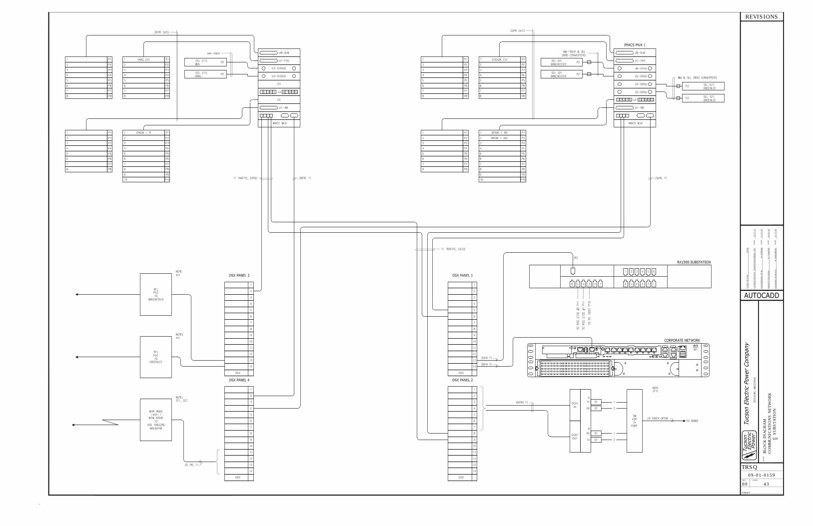
ATTACHMENT G: BLOCK DIAGRAM ― 345 KV SWITCHYARD COMMUNICATION BLOCK DIAGRAM
Q19
TIT
LE:
CODE
TU
CSO
N,
ARIZ
ON
A
SHEET
TRSQ
REV
DATE
SCALE
FACTO
R:
CO
NTRACTED
EN
G:
DATE
EN
GIN
EERIN
G T
ECH
:
PRO
JECT E
NG
INEER:
EN
GIN
EER A
PPRO
VAL:
DATE
DATE
REVISIONS
BLO
CK D
IAG
RAM
CO
MM
UN
ICATIO
NS N
ETW
ORK
SU
BSTATIO
N
09-01-0159
00 43
NO
NE
POW
ER E
NG
INEERS,
INC
12/1
7/1
2
M.
FARN
AM
01/2
7/0
9
D.
CAN
SLE
R09-0
1-0
9
B.
EH
LEN
BU
RG
01/2
7/0
9
Q19
POWER ENGINEERS, INC.
PHX 128-120 127695 (08/28/2013) GG PAGE 18 REV. 7
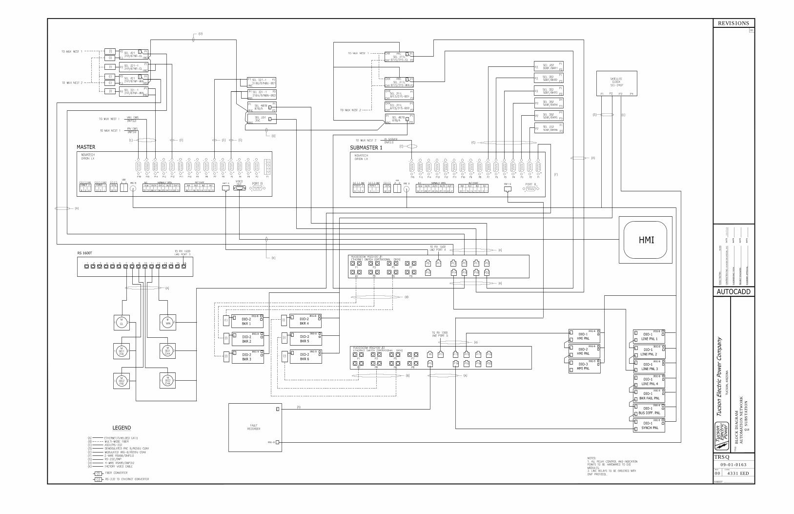
ATTACHMENT H: BLOCK DIAGRAM ― 345 KV SWITCHYARD AUTOMATION BLOCK DIAGRAM
Q19
CODE
SHEET
TRSQ
REV
REVISIONS
BLO
CK D
IAG
RAM
AU
TO
MATIO
N N
ETW
ORK
SU
BSTATIO
N
09-01-0163
00 4331 EED
NO
NE
POW
ER E
NG
INEERS,
INC
12/1
7/1
2
Q19