faarfild airport pavement design
TRANSCRIPT

8/3/2019 FAARFILD Airport Pavement Design
http://slidepdf.com/reader/full/faarfild-airport-pavement-design 1/109
FAA Pavem ent Design : AC
150/5320-6E – FAARFIELD
Presented to ACPA Southeast Chapter Workshop
October 21, 2008
Gary L. Mitchell, P.E.
Director of Airports
American Concrete Pavement Association

8/3/2019 FAARFILD Airport Pavement Design
http://slidepdf.com/reader/full/faarfild-airport-pavement-design 2/109
FAA Pavem ent Design
AC 150/5320-6E, Airport Pavement Design and
Evaluation – Com letel revised in 2008
– New design methodologies for Rigid and Flexible
pavements
– Software dependent design procedures
– Addresses modern air lane arameters

8/3/2019 FAARFILD Airport Pavement Design
http://slidepdf.com/reader/full/faarfild-airport-pavement-design 3/109
So i l Invest igat ions andva ua on

8/3/2019 FAARFILD Airport Pavement Design
http://slidepdf.com/reader/full/faarfild-airport-pavement-design 4/109
Chapt er 2
Soi l Invest igat ions and Evaluat ion
Very few significant changes
Still uses Unified Soil Classification (USC) system
50
60
GW CL
30
40
Y I N D E X ( P I )
GM OL
GC CH
SW MH
10
20
P L A S T I C
I
MH - OH
SP OH
SM PT
SC
0
0 10 20 30 40 50 60 70 80 90 100 110
LIQUID LIMIT (LL)
CL - ML ML - OH

8/3/2019 FAARFILD Airport Pavement Design
http://slidepdf.com/reader/full/faarfild-airport-pavement-design 5/109
Chapt er 2
Soi l Invest igat ions and Evaluat ion
Same minimum subsurface borin recommendations
Same soil testing recommendations
AREA Minimum spacing Minimum depth
RWY/TWY 200 ft interval 10 ft
Other areas 1 er 10,000 s ft 10 ft
Borrow areas As necessary As necessary

8/3/2019 FAARFILD Airport Pavement Design
http://slidepdf.com/reader/full/faarfild-airport-pavement-design 6/109
Chapt er 2
Soi l Invest igat ions and Evaluat ion
Continues to split soil compaction requirements
based upon 60,000 lb gross weight airplane< 60000 ASTM D 698 Standard Proctor
> 60,000 ASTM D 1557 Modified Proctor

8/3/2019 FAARFILD Airport Pavement Design
http://slidepdf.com/reader/full/faarfild-airport-pavement-design 7/109
Chapt er 2
Soi l Invest igat ions and Evaluat ion
Soil Strength Parameter for RIGID pavement
Resilient Modulus E (psi) or
Modulus of Subgrade Reaction –k-value (pci)
Design value – “conservative selection”K-value can be estimated from CBR
7788.0CBR1500×
26 ⎥⎦⎢⎣= (k in pci)

8/3/2019 FAARFILD Airport Pavement Design
http://slidepdf.com/reader/full/faarfild-airport-pavement-design 8/109
Chapt er 2
Soi l Invest igat ions and Evaluat ion
Modulus of Subgrade Reaction –k-value (pci)
• Removed the statement:“ -
estimating k will not have a large impact on rigid pavement
thickness”
Design comparisons show that FAAFIELD thickness design is
more sens ve o -vaue conver e o an e prevousWestergaard-based procedure.

8/3/2019 FAARFILD Airport Pavement Design
http://slidepdf.com/reader/full/faarfild-airport-pavement-design 9/109
Chapt er 2
Soi l Invest igat ions and Evaluat ion
Soil Strength Parameter for RIGID pavement
k-value (pci)With the 3D finite element design procedure
e sens v y o -vaue o rg esgn s
increased. Errors in selection of k-value can
generate noticeable changes in the requiredavement thickness.
20
22
e s s ( i n )
K = 200PCC = 16.14
12
14
16
P C C t h i c k
K = 150PCC = 17.38
10
0 50 100 150 200 250 300 350 400k-value
Example not indicative of all situations

8/3/2019 FAARFILD Airport Pavement Design
http://slidepdf.com/reader/full/faarfild-airport-pavement-design 10/109
Chapt er 2
Soi l Invest igat ions and Evaluat ion
Seasonal Frost
Same Frost Groups (FG-1, FG-2, FG-3 & FG-4)
Determination of Depth of Frost Penetration
i.e. local construction practice, building codes, etc.
No nomographs or programs provided

8/3/2019 FAARFILD Airport Pavement Design
http://slidepdf.com/reader/full/faarfild-airport-pavement-design 11/109
Pavem ent Design

8/3/2019 FAARFILD Airport Pavement Design
http://slidepdf.com/reader/full/faarfild-airport-pavement-design 12/109
Chapt er 3 - Pavem ent Des ign
Completely New Chapter
Covers standard pavement design procedures for both flexible andrigid pavement
Applies to pavement designed for airplanes with gross weights
exceeding 30,000 lbs
esgn proce ure requres e use o compuer program, .e.
FAARFIELD

8/3/2019 FAARFILD Airport Pavement Design
http://slidepdf.com/reader/full/faarfild-airport-pavement-design 13/109
Chapt er 3 - Pavem ent Des ign
FAARFIELD 1.0 – Sc reen Shot s
Main Window StructureWindow
OptionsWindow

8/3/2019 FAARFILD Airport Pavement Design
http://slidepdf.com/reader/full/faarfild-airport-pavement-design 14/109
Chapt er 3 - Pavem ent Des ign
Rigid Pavement Design based on 3-Dimensional Finite Element
mo e
Westergaard design procedure no longer used.
Flexible Pavement Design based on Layered Elastic design
US Corp of Engineers CBR Method no longer used
8/3/2019 FAARFILD Airport Pavement Design
http://slidepdf.com/reader/full/faarfild-airport-pavement-design 15/109
Chapt er 3 - Pavem ent Des ign
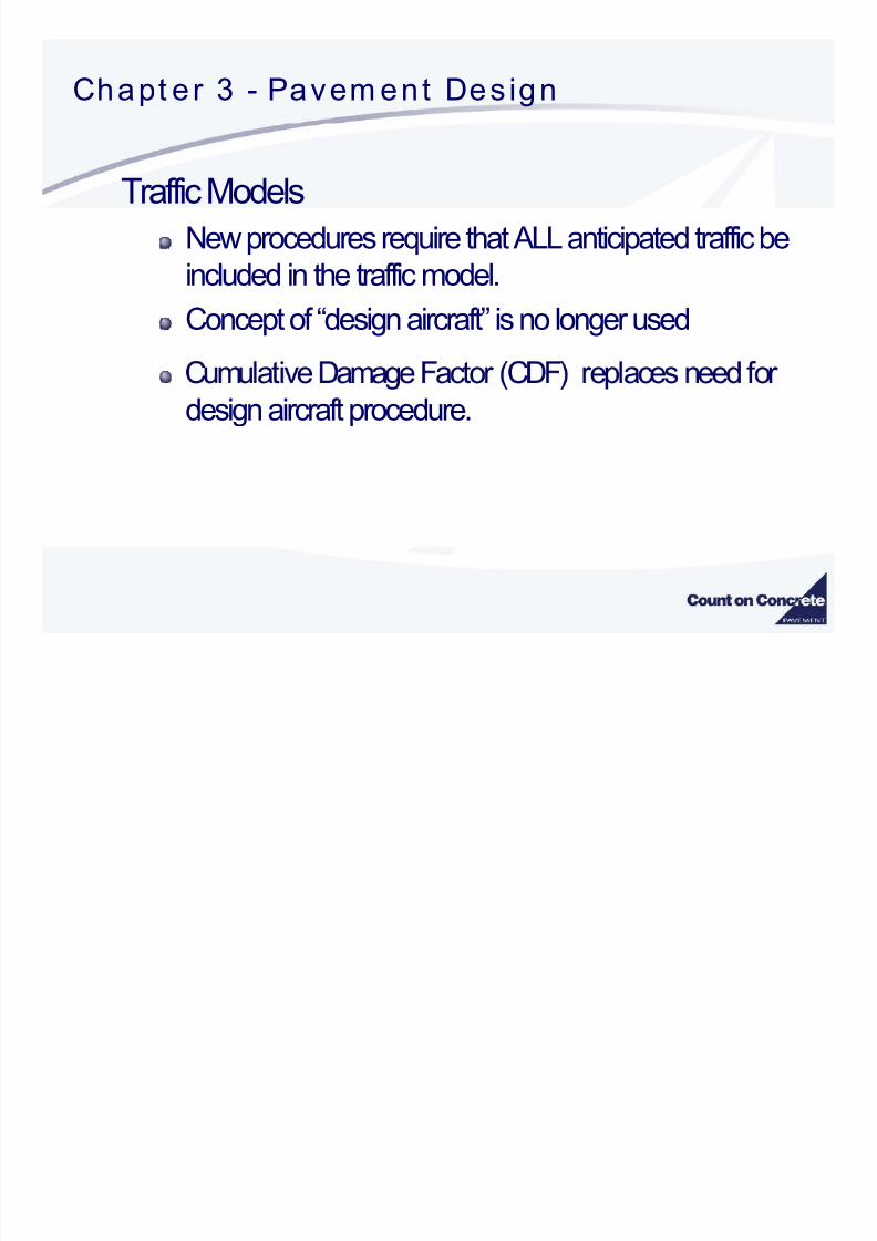
Traffic Models
New procedures require that ALL anticipated traffic beincluded in the traffic model.
Concept of “design aircraft” is no longer used
design aircraft procedure.

8/3/2019 FAARFILD Airport Pavement Design
http://slidepdf.com/reader/full/faarfild-airport-pavement-design 16/109
Chapt er 3 - Pavem ent Des ign
Traffic Model - Cumulative Dama e Facto
Sums Damage FromEach AircraftBased upon its unique pavement loading characteristics and
Location of the main gear from centerline
DOES NOT use the “design aircraft” method of condensing
all aircraft into one design model

8/3/2019 FAARFILD Airport Pavement Design
http://slidepdf.com/reader/full/faarfild-airport-pavement-design 17/109
Chapt er 3 - Pavem ent Des ign
Traffic Model - Cumulative Dama e Facto
Sums Damage FromEach Aircraft - Not From “Design Aircraft”
failuretosrepetitionallowableof number
srepetitionloadappliedof numberCDF =
When CDF = 1, Design Life is Exhausted

8/3/2019 FAARFILD Airport Pavement Design
http://slidepdf.com/reader/full/faarfild-airport-pavement-design 18/109
Chapt er 3 - Pavem ent Des ign
Traffic Model - Cumulative Dama e Facto
CDF is Calculated for each 10 inch wide strip over a total820 inch width.
Each strip treated as a 30X30 panel for analysis
Gear location and wander considered for each aircraft
Use Miner’s rule to sum damage for each strip
Must Input Traffic Mix, NOT“Design Aircraft”
8/3/2019 FAARFILD Airport Pavement Design
http://slidepdf.com/reader/full/faarfild-airport-pavement-design 19/109
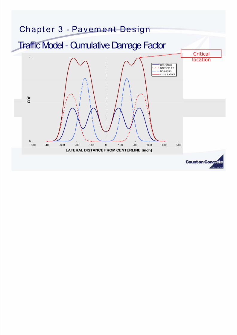
Chapt er 3 - Pavem ent Des ignTraffic Model - Cumulative Damage Factor
Critical1
B747-200BB777-200 ER
DC8-63/73
CUMULATIVE
location
D F
0
-500 -400 -300 -200 -100 0 100 200 300 400 500
LATERAL DISTANCE FROM CENTERLINE [inch]

8/3/2019 FAARFILD Airport Pavement Design
http://slidepdf.com/reader/full/faarfild-airport-pavement-design 20/109
Chapt er 3 - Pavem ent Des ignTraffic Model - Cumulative Damage Factor

8/3/2019 FAARFILD Airport Pavement Design
http://slidepdf.com/reader/full/faarfild-airport-pavement-design 21/109
Sam le A ir c ra ft T raf f i c M ix CDF Cont r ibut ion Annual CDF CDF Max
Aircraft Name Gross Weight Departures Contribution For Aircraft
Sn l Whl-30 30 000 1 200 0.00 0.00
Dual Whl-30 30,000 1,200 0.00 0.00
Dual Whl-45 45,000 1,200 0.00 0.00
RegionalJet-200 47,450 1,200 0.00 0.00
RegionalJet-700 72,500 1,200 0.00 0.00
Dual Whl-100 100,000 1,200 0.00 0.00
DC-9-51 122,000 1,200 0.02 0.02- , , . .
B-737-400 150,500 1,200 0.09 0.09
B-727 172,000 1,200 0.17 0.17
B-757 250,000 1,200 0.02 0.04
A300-B2 304,000 1,200 0.03 0.14B-767-200 335,000 1,200 0.01 0.13
A330 469,000 100 0.01 0.14
Condition specific and not a general representation of noted aircraft
- - , . .
B-777-200 537,000 500 0.00 0.14

8/3/2019 FAARFILD Airport Pavement Design
http://slidepdf.com/reader/full/faarfild-airport-pavement-design 22/109
C D
F
Condition specific and not a general representation of noted aircraft

8/3/2019 FAARFILD Airport Pavement Design
http://slidepdf.com/reader/full/faarfild-airport-pavement-design 23/109
Condition specific and not a general representation of noted aircraft

8/3/2019 FAARFILD Airport Pavement Design
http://slidepdf.com/reader/full/faarfild-airport-pavement-design 24/109
Large A i rc ra f t T ra f f ic Mix Gear Loc at ions
B-777-200
B-747-400
i n e
.
-330
B-767-200A-300-B2
B-757
y C e n t e r l B-727
B-737-400
MD-83
MD-90-30
R u n w
DC-9-50
DW 100,000
Regional Jet 700
Regional Jet 200
DW 45,000DW 30,000
SW 30,000
0 25 50 75 100 125 150 175 200 225 250 275 300 325 350 375 400
Distance From Centerline (in)

8/3/2019 FAARFILD Airport Pavement Design
http://slidepdf.com/reader/full/faarfild-airport-pavement-design 25/109
Chapt er 3 - Pavem ent Des ign
Remember
Must use the entire traffic mixture
No more “Design Aircraft”
Comparisons between new and previous design procedures using “designaircraft” for the traffic model will result in significant errors

8/3/2019 FAARFILD Airport Pavement Design
http://slidepdf.com/reader/full/faarfild-airport-pavement-design 26/109
Chapt er 3 - Pavem ent Des ign
Traffic Model –Airplane Characteristics
FAARFIELD program currently provides 198 differentaircraft models
Each model is unique with respect to gross load, load
distribution, wheel spacing, and tire pressureGear types identified in accordance with FAA Order
5300.7
Eliminates “widebody” terminolog

8/3/2019 FAARFILD Airport Pavement Design
http://slidepdf.com/reader/full/faarfild-airport-pavement-design 27/109
Chapt er 3 - Pavem ent Des ign
Traffic Model – Gear Naming Convention
# of gear types in tandem Total # of body/ belly gears(Because body/belly gear may not(A value of 1 is omitted for
Gear type, e.g. S, D, T, or Q
# of main gears in line on
e symme r ca , e gear musidentify the total number of gearspresent and a value of 1 is notomitted if only one gear exists.)
s mp c y.
one s e o e a rcra , . . , , ,
# of gear types in tandem(Assumes gear is present on bothsides. The value indicates numberof gears on one side. A value of 1is omitted for simplicity.)
(A value of 1 is omitted forsim licit .
8/3/2019 FAARFILD Airport Pavement Design
http://slidepdf.com/reader/full/faarfild-airport-pavement-design 28/109
Chapt er 3 - Pavem ent Des ign
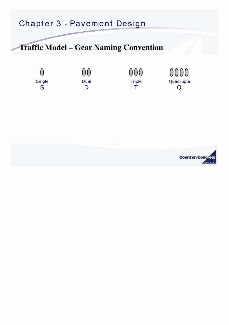
Traffic Model – Gear Naming Convention
Single
SDual
DTriple
TQuadruple
Q
8/3/2019 FAARFILD Airport Pavement Design
http://slidepdf.com/reader/full/faarfild-airport-pavement-design 29/109
Chapt er 3 - Pavem ent Des ign
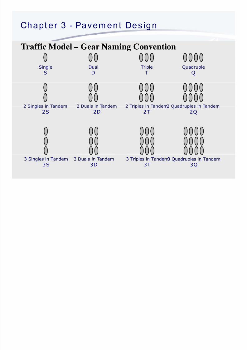
Traffic Model – Gear Naming Convention
SingleS DualD TripleT QuadrupleQ
2S
2D
2T
2Q
3 Singles in Tandem
3S3 Duals in Tandem
3D3 Triples in Tandem
3T3 Quadruples in Tandem
3Q

8/3/2019 FAARFILD Airport Pavement Design
http://slidepdf.com/reader/full/faarfild-airport-pavement-design 30/109
Chapt er 3 - Pavem ent Des ign --
Examples
2D
Single Wheel Dual WheelDual Tandem
2D/2D1A340-600
3D 2D/D1DC-10

8/3/2019 FAARFILD Airport Pavement Design
http://slidepdf.com/reader/full/faarfild-airport-pavement-design 31/109
Chapt er 3 - Pavem ent Des ign --
2D/2D2B747
2D/3D2A380
C5Lockheed C5

8/3/2019 FAARFILD Airport Pavement Design
http://slidepdf.com/reader/full/faarfild-airport-pavement-design 32/109
Chapt er 3 - Pavem ent Des ign
Traffic Model –Pass to Coverage (P/C) Ratio
Lateral movement is known as airplane wander and ismodel by statistically normal distribution.
Standard Deviation = 30.435 inches (773 mm)
(P/C) -The ratio of the number of trips (or passes)along the pavement for a specific point on the
pavement to receive one full-load application.
-6E utilizes new procedure for determining P/C

8/3/2019 FAARFILD Airport Pavement Design
http://slidepdf.com/reader/full/faarfild-airport-pavement-design 33/109
Chapt er 3 - Pavem ent Des ign
Traffic Model –Pass to Coverage (P/C) Ratio
Rigid PavementOne Coverage = One full stress application to the
bottom of the
PCC layer
Flexible Pavement
of the
subgrade layer

8/3/2019 FAARFILD Airport Pavement Design
http://slidepdf.com/reader/full/faarfild-airport-pavement-design 34/109
Chapt er 3 - Pavem ent Des ign
Traffic Model –Pass to Coverage (P/C) Ratio
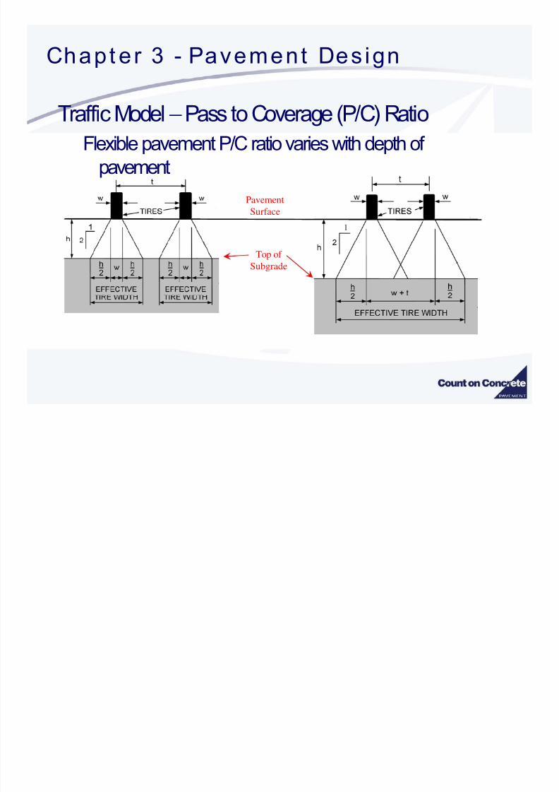
-6E (FAARFIELD) uses the concept of “Effective TireWidth”
Rigid Pavement –Effective width is defined at the
surface of the pavement (equal to tire contact patch)(same as previous P/C procedures)
Flexible Pavement Effective width is defined at thesurface of the subgrade layer
8/3/2019 FAARFILD Airport Pavement Design
http://slidepdf.com/reader/full/faarfild-airport-pavement-design 35/109
Chapt er 3 - Pavement Des ign
Traffic Model –Pass to Coverage (P/C) Ratio
Flexible pavement P/C ratio varies with depth of
pavement
Pavement
Surface
Top of
Subgrade

8/3/2019 FAARFILD Airport Pavement Design
http://slidepdf.com/reader/full/faarfild-airport-pavement-design 36/109
Chapt er 3 - Pavem ent Des ign Typic a l

8/3/2019 FAARFILD Airport Pavement Design
http://slidepdf.com/reader/full/faarfild-airport-pavement-design 37/109
Chapt er 3 Pavem ent Des ign Typic a l
Sect ions
Air ort avements are enerall constructed in
uniform, full width sections
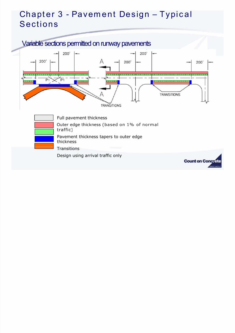
Variable sections are permitted on runway pavements
Designer should consider:Practical feasibility –complex construction operations
Economical feasibility –cost of complex construction
8/3/2019 FAARFILD Airport Pavement Design
http://slidepdf.com/reader/full/faarfild-airport-pavement-design 38/109
Chapt er 3 - Pavem ent Des ign Typic a l

8/3/2019 FAARFILD Airport Pavement Design
http://slidepdf.com/reader/full/faarfild-airport-pavement-design 39/109
Chapt er 3 Pavem ent Des ign Typic a l
Sect ions
Variable sections permitted on runway pavements
1. Minimum 12” u to 36”
2. For runways wider than
150’, this dimension willincrease.
. o apers antransitions on rigidpavements must be aneven multiple of slabs,
minimum one slab width.1
Full pavement thickness
2
3
2
uter e ge t c ness
traffic)
Pavement thickness tapers
to outer edge thickness

8/3/2019 FAARFILD Airport Pavement Design
http://slidepdf.com/reader/full/faarfild-airport-pavement-design 40/109
- ,Evaluation
–,
Chapt er 3 Sec t ion 3 Rig id Pavem ent

8/3/2019 FAARFILD Airport Pavement Design
http://slidepdf.com/reader/full/faarfild-airport-pavement-design 41/109
Chapt er 3 Sec t ion 3 Rig id Pavem ent
Design
Portland Cement Concrete (PCC)
Subbase Course **
Subgrade
** Stabilization required when airplanes exceeding 100,000 lbs are in the trafficmixture.

8/3/2019 FAARFILD Airport Pavement Design
http://slidepdf.com/reader/full/faarfild-airport-pavement-design 42/109

8/3/2019 FAARFILD Airport Pavement Design
http://slidepdf.com/reader/full/faarfild-airport-pavement-design 43/109
Chapt er 3 Sec t ion 3 – Rig id Pavement
3-Dimensional Finite Element Design
NEW procedure Ri id desi n uses 3-D finite element method 3D-FEM
for direct calculation of stress at the edge of a concrete
slab.
Predictor of pavement life
• Maximum Stress at pavement edge
• Assumed failure osition – bottom at slab ed e
Ch t 3 S t i 3 Ri id P t

8/3/2019 FAARFILD Airport Pavement Design
http://slidepdf.com/reader/full/faarfild-airport-pavement-design 44/109
Chapt er 3 Sec t ion 3 – Rig id Pavement
• Maximum stress at pavement edge
LOAD
• oa rans er to a acent s a
SubgradeMaximum Stress
Bottom of Slab
Ch t 3 S t i 3 Ri id P t

8/3/2019 FAARFILD Airport Pavement Design
http://slidepdf.com/reader/full/faarfild-airport-pavement-design 45/109
Chapt er 3 Sec t ion 3 – Rig id Pavement
• Maximum stress at pavement edge
LOAD
• oa rans er to a acent s a
SubgradeMaximum Stress
Bottom of Slab
Chapt er 3 Sec t ion 3 Rig id Pavement

8/3/2019 FAARFILD Airport Pavement Design
http://slidepdf.com/reader/full/faarfild-airport-pavement-design 46/109
Chapt er 3 Sec t ion 3 – Rig id Pavement
Desi n
TOP DOWN CRACKING DUE TO EDGE OR CORNER
• Maximum stress due to corner or edge loading condition
• -
• These conditions may need to be addressed in future procedures
Maximum Stress
LOAD
Top of Slab
Chapt er 3 Sec t ion 3 Rig id Pavement

8/3/2019 FAARFILD Airport Pavement Design
http://slidepdf.com/reader/full/faarfild-airport-pavement-design 47/109
Chapt er 3 Sec t ion 3 – Rig id Pavement

8/3/2019 FAARFILD Airport Pavement Design
http://slidepdf.com/reader/full/faarfild-airport-pavement-design 48/109
Chapt er 3 Sec t ion 3 Rig id Pavement

8/3/2019 FAARFILD Airport Pavement Design
http://slidepdf.com/reader/full/faarfild-airport-pavement-design 49/109
Chapt er 3 Sec t ion 3 – Rig id Pavement
Possible Critical Load Locations- Considering SlabCurling
-Up Crack
-Down Crack
Chapte r 3 Sec t ion 3 Rigid Pavement

8/3/2019 FAARFILD Airport Pavement Design
http://slidepdf.com/reader/full/faarfild-airport-pavement-design 50/109
Chapte r 3 Sec t ion 3 – Rigid Pavement
Pavement Structural Design Life
• e au t es gn e s or years
• Structural design life indicates pavement performance in terms of allowable load repetitions before SCI = 80.
• Structural life is determined based upon annual departures multiplied by
20 (yrs). This value may or may not correlate with calendar years
de endin u on actual avement use.
• Pavement performance in terms of surface condition and other distresses
which might affect the use of the pavement by airplanes is not directly
.
Chapter 3 Section 3

8/3/2019 FAARFILD Airport Pavement Design
http://slidepdf.com/reader/full/faarfild-airport-pavement-design 51/109
Rigid Failure Model as Implemented in
⎤⎡⎤⎡ SCI
Rigid pavement failure model in FAARFIELD
⎥⎥⎢⎢ ′+− ⎞⎛
−
+− ⎠⎝
−
+×⎥⎥⎢⎢ ′+− ⎞⎛
−
′
=bF bd
SCI
cca
C bF bd
SCI
bd F
F
DF s
s
c 1
100log
1
where:
⎦⎣⎦⎣ 100100
a = 0.5878, b = 0.2523, c = 0.7409, d = 0.2465,
C = coverages
SCI = Structural Condition Index
Fs’ = is a compensation factor that accounts for a high-stiffness(stabilized) base.
c .Note: Equation is linear in log (C ) for any value of
This is a departure from LEDFAA rigid failure model.sF ′
Chapt er 3 Sec t ion 3 Rig id Pavem ent
Design
8/3/2019 FAARFILD Airport Pavement Design
http://slidepdf.com/reader/full/faarfild-airport-pavement-design 52/109
Design
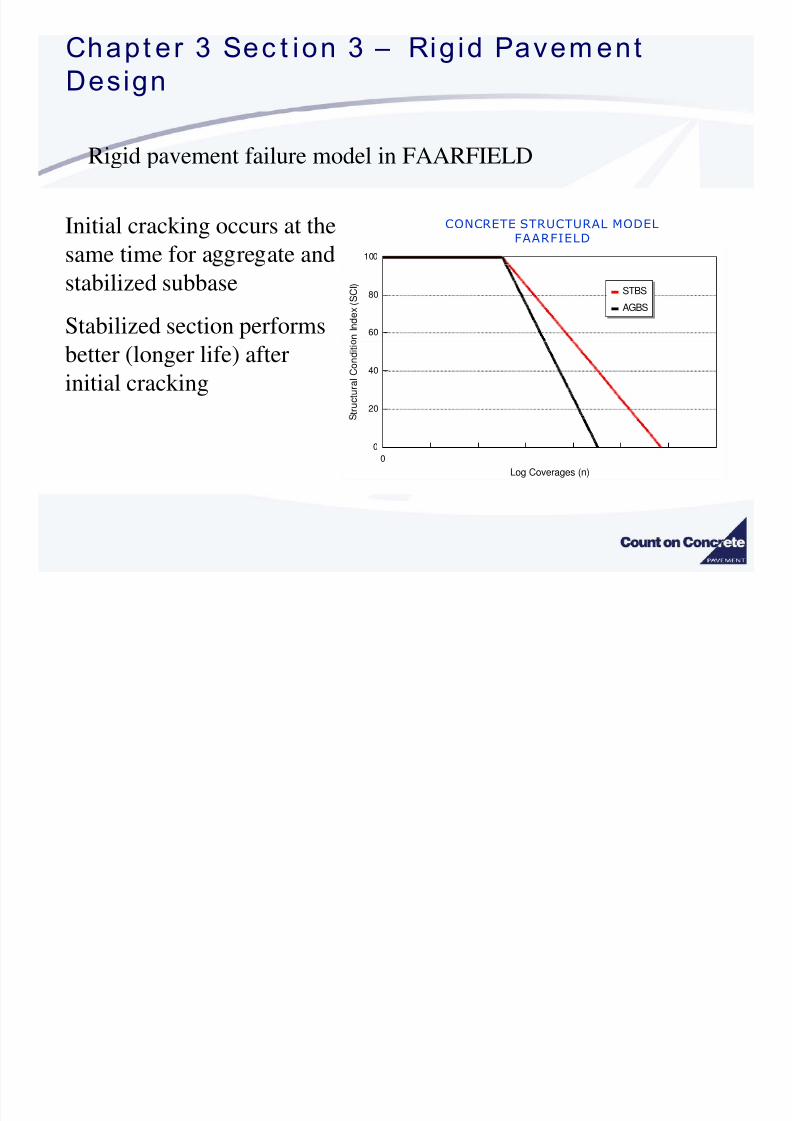
Rigid pavement failure model in FAARFIELD
Initial cracking occurs at thesame time for a re ate and 100
CONCRETE STRUCTURAL MODELFAARFIELD
stabilized subbase
Stabilized section performs 60
80
n
I n d e x ( S C I )
STBS
AGBS
better (longer life) after
initial cracking20
40
t r u c t u r a l C o n d i t i
0
0
Log Coverages (n)
Rigid Failure Model as

8/3/2019 FAARFILD Airport Pavement Design
http://slidepdf.com/reader/full/faarfild-airport-pavement-design 53/109
Rigid Failure Model as
⎤⎡′⎛ ⎤⎡ SCI
⎥⎥⎢⎢ ′+− ⎞⎛
−
− ⎠⎝
−
+×⎥⎥⎢⎢ ′+− ⎞⎛
−
′
=bF bd
SCI C bF bd
SCI
bd F
F
DF s
s
c 1
100log
1⎦⎣⎦⎣ 100100
is the calibration, or scaling, factor. It is not derived from
analysis of full-scale data, but rather from comparison of the
cF
unca ra e a ure mo e w correspon ng es gns ase on
the design chart method in AC 150/5320-6D. In FAARFIELD
1.1 has a value of 1.13.
c
F
FAARFIELD versus West ergaard

8/3/2019 FAARFILD Airport Pavement Design
http://slidepdf.com/reader/full/faarfild-airport-pavement-design 54/109
Traffic Mix #4 - MEMPHIS RWY 18R
g
25.00
.
.
R805FAA / COMFAA 2.0
LEDFAA 1.3
FAARFIELD 1.003 (Fc=1.13)
23.00
h i c k n e s s , i
19.00
.
C
C
D e s i g n
17.00
.
P 3 0 1
P 3 0 4
P 3 0 6
P 3 0 1
P 3 0 4
P 3 0 6
P 3 0 1
P 3 0 4
P 3 0 6
P 3 0 1
P 3 0 4
P 3 0 6
P 3 0 1
P 3 0 4
P 3 0 6
P 3 0 1
P 3 0 4
P 3 0 6
P 3 0 1
P 3 0 4
P 3 0 6
P 3 0 1
P 3 0 4
P 3 0 6
P 3 0 1
P 3 0 4
P 3 0 6
P 3 0 1
P 3 0 4
P 3 0 6
P 3 0 1
P 3 0 4
P 3 0 6
P 3 0 1
P 3 0 4
P 3 0 6
E = 7.5 ksi E = 15 ksi E = 25 ksi E = 7.5 ksi E = 15 ksi E = 25 ksi E = 7.5 ksi E = 15 ksi E = 25 ksi E = 7.5 ksi E = 15 ksi E = 25 ksi
MEM RWY 18R-36L - All traffic MEM RWY 18R-36L - no B777 MEM RWY 18R-36L - All traffic MEM RWY 18R-36L - no B777
= =
FAARFIELD versus West ergaard

8/3/2019 FAARFILD Airport Pavement Design
http://slidepdf.com/reader/full/faarfild-airport-pavement-design 55/109
FAARFIELD versus West ergaard
Mix 3 - IAD RWY 1L (B727 design aircraft)
27.00R805FAA / COMFAA 2.0
LEDFAA 1.3
FAARFIELD 1.003 Fc=1.13
23.00
25.00
, i n .
. .
21.00
D e s i g n T h i c k n e s s
17.00
19.00 P C C
15.00P301 P304 P306 P301 P304 P306 P301 P304 P306 P301 P304 P306 P301 P304 P306 P301 P304 P306 P301 P304 P306 P301 P304 P306 P301 P304 P306 P301 P304 P306 P301 P304 P306 P301 P304 P306
E = 7.5 ksi E = 15 ksi E = 25 ksi E = 7.5 ksi E = 15 ksi E = 25 ksi E = 7.5 ksi E = 15 ksi E = 25 ksi E = 7.5 ksi E = 15 ksi E = 25 ksi
Dulles RWY 1L - All traffic Dulles RWY 1L - No B777, A340 Dulles RWY 1L - All traffic Dulles RWY 1L - No B777
R = 500 psi R = 650 psi
Chapt er 3 - Pavement Des ign

8/3/2019 FAARFILD Airport Pavement Design
http://slidepdf.com/reader/full/faarfild-airport-pavement-design 56/109
Chapt er 3 Pavement Des ign
Westergaard FAARFIELDprocedure procedure
18.26” PCC
8” Stabilized Base
17.38” PCC
(17.61 with P401 base)
” -
SUBGRADE k = 160
Chapt er 3 - Pavement Des ign

8/3/2019 FAARFILD Airport Pavement Design
http://slidepdf.com/reader/full/faarfild-airport-pavement-design 57/109
Chapt er 3 Pavement Des ign
Westergaard FAARFIELD
procedure procedure
18.25 “ PCC
16.52 “ PCC
Effective
k=323
8” Stabilized Base
=
SUBGRADE k = 323
Chapt er 3 Sec t ion 3 – Rig id Pavement

8/3/2019 FAARFILD Airport Pavement Design
http://slidepdf.com/reader/full/faarfild-airport-pavement-design 58/109
REQUIRED INPUT VARIABLES
Subgrade support conditions
k-value or Modulus
aera proper es o eac ayeModulus for all layers (flexural strength for PCC)
Poisson’s Ratio –fixed in FAARFIELD
Traffic
Frequency of load applicationAirplane characteristics
, ,
Chapt er 3 Sec t ion 3 – Rig id Pavement

8/3/2019 FAARFILD Airport Pavement Design
http://slidepdf.com/reader/full/faarfild-airport-pavement-design 59/109
p g
Subgrade Characteristics
FAARFIELD accepts Resilient Modulus ESG or k-value
• Converts k-value to modulus
284.1
26k E =
ESG = Resilient modulus of subgrade, in psi
k = Foundation modulus of the subgrade, in pciAASHTO T 222, Nonrepetitive Static Plate Load Test of Soils and Flexible
Pavement Components, for Use in Evaluation and Design of Airport and Highwayavemen s
Chapt er 3 Sec t ion 3 Rig id Pavem ent
Design

8/3/2019 FAARFILD Airport Pavement Design
http://slidepdf.com/reader/full/faarfild-airport-pavement-design 60/109
Design
Subgrade Characteristics
k-value can be estimated from CBR value
7788.0
26 ⎥⎦
⎢⎣
=k
k = Foundation modulus of the subgrade, in pci
Allowable range of k-value in FAARFIELD – 17.2 to 361.1

8/3/2019 FAARFILD Airport Pavement Design
http://slidepdf.com/reader/full/faarfild-airport-pavement-design 61/109
Chapt er 3 Sec t ion 3 Rig id Pavem ent
Design

8/3/2019 FAARFILD Airport Pavement Design
http://slidepdf.com/reader/full/faarfild-airport-pavement-design 62/109
g
Subbase Layer Characteristics
Stabilization required with airplanes exceed 100,000 lbs
Aggregate materials - modulus dependent on thickness
Modulus calculated by FAARFIELD based on thickness
4 inch minimum thickness requirement
Chapt er 3 Sec t ion 3 Rig id Pavem ent
Design

8/3/2019 FAARFILD Airport Pavement Design
http://slidepdf.com/reader/full/faarfild-airport-pavement-design 63/109
g
Portland Cement Concrete Layer Characteristics
P-501
FAA recommends 600 –700 psi for design purposes
FAARFIELD will allow 500 –800 psiASTM C 78 Flexural Strength of Concrete (Using SimpleBeam with Third-Point Loading)
6 Inch minimum thickness requirementThickness rounded to the nearest 0.5 inch
Chapt er 3 Sec t ion 3 Rig id Pavem ent
Design

8/3/2019 FAARFILD Airport Pavement Design
http://slidepdf.com/reader/full/faarfild-airport-pavement-design 64/109
g
Design Flexural Strength versus P-501 Specification
esgn reng can e greaer an - - ay
strength e.g. - = ps en esgn a ps
Factors to Consider:
Flexural strength vs. cement content data from prior projects at the airport
Need to avoid high cement contents, which can affect concrete durability
Whether early opening requirements necessitate using a lower strength than 28-day
ASR Concerns
Chapt er 3 Sec t ion 3 – Rig id Pavement

8/3/2019 FAARFILD Airport Pavement Design
http://slidepdf.com/reader/full/faarfild-airport-pavement-design 65/109
Traffic Input for Rigid Pavement Design
Airplane characteristics
198 Airplane models currently available in FAARFIELD
ee oa etermne automatca y ase on gross
weight
Tire pressure – Internal to FAARFIELD aircraft library
Fre uenc of load a lication
Entered as annual departuresArrival traffic ignored
User determines percent of total
airport volume
Chapter 3 Section 3 – Rigid PavementDesign

8/3/2019 FAARFILD Airport Pavement Design
http://slidepdf.com/reader/full/faarfild-airport-pavement-design 66/109
Design
FAArfield – Gear Alignment on slab edge
a slab.
•FAARFIELD makes this determination.
3-D Finite Element Model

8/3/2019 FAARFILD Airport Pavement Design
http://slidepdf.com/reader/full/faarfild-airport-pavement-design 67/109
Chapt er 3 Sec t ion 3 – Rig id Pavement

8/3/2019 FAARFILD Airport Pavement Design
http://slidepdf.com/reader/full/faarfild-airport-pavement-design 68/109
Chapt er 3 Sec t ion 3 Rig id Pavement
Design
-
Correctly models rigid pavement- .
Provides the complete stress and
dis lacement fields for the anal zed domain. Handles complex load configurations easily.
or material types.
.
Chapter 3 Section 3 – Rigid Pavement

8/3/2019 FAARFILD Airport Pavement Design
http://slidepdf.com/reader/full/faarfild-airport-pavement-design 69/109
Disadvantages of 3D-FEM May require long computation times.
Pre-processing and post-processing requirements.
Solution are mesh-dependent.
• In theory, the solution can always be improved by refining the 3D mesh.
• .
Chapter 3 Section 3 – Rigid PavementDesign

8/3/2019 FAARFILD Airport Pavement Design
http://slidepdf.com/reader/full/faarfild-airport-pavement-design 70/109
Design
3D Finite Element is:
A method of structural analysis.
A licable to a wide ran e of h sical structures
boundary and loading conditions.
3D Finite Element is not:A design method or procedure.
.
Always preferable to other analysis models.
Chapter 3 Section 3 – Rigid PavementDesign

8/3/2019 FAARFILD Airport Pavement Design
http://slidepdf.com/reader/full/faarfild-airport-pavement-design 71/109
g
Structures and ModelsIn finite element analysis, it is important to distinguish:
The physical structure
The idealized model
The discretized (approximate)
model
Chapter 3 Section 3 – Rigid PavementDesign

8/3/2019 FAARFILD Airport Pavement Design
http://slidepdf.com/reader/full/faarfild-airport-pavement-design 72/109
g
Improvement in Solution Time
Approximate time for B-777 stress solution:• July 2000: 4 - 5 hours
• July 2001: 30 minutes
(single slab with infinite element foundation)
• Ma 2002: 2 - 3 minute (implement new incompatible modes elements)
• Current version implemented in FAARFIELD:
10 seconds or les

8/3/2019 FAARFILD Airport Pavement Design
http://slidepdf.com/reader/full/faarfild-airport-pavement-design 73/109
Design
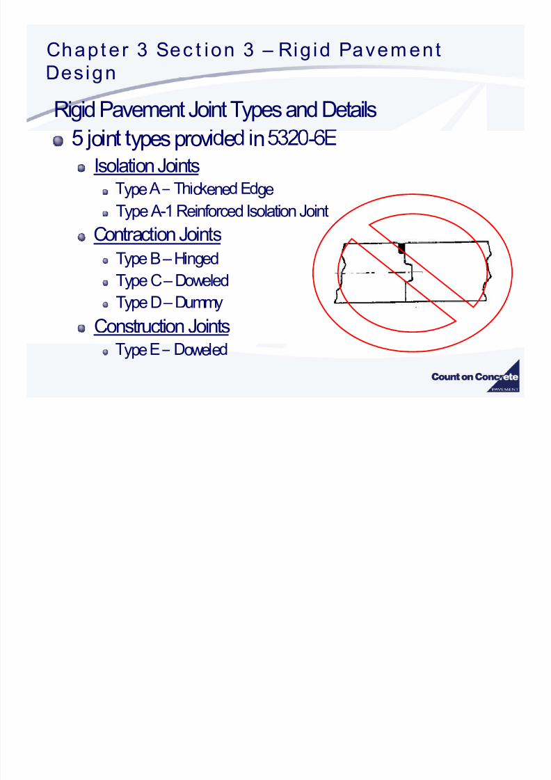
Rigid Pavement Joint Types and Details
8/3/2019 FAARFILD Airport Pavement Design
http://slidepdf.com/reader/full/faarfild-airport-pavement-design 74/109
Chapt er 3 Sec t ion 3 Rig id Pavem ent
Design

8/3/2019 FAARFILD Airport Pavement Design
http://slidepdf.com/reader/full/faarfild-airport-pavement-design 75/109
Rigid Pavement Joint Types and Details
Isolation Joints
Type A –Thickened Edge
Chapt er 3 Sec t ion 3 – Rig id Pavement

8/3/2019 FAARFILD Airport Pavement Design
http://slidepdf.com/reader/full/faarfild-airport-pavement-design 76/109
es gnRigid Pavement Joint Types and Details
Isolation Joints
Type A-1 –Reinforced
Chapt er 3 Sec t ion 3 – Rig id Pavement

8/3/2019 FAARFILD Airport Pavement Design
http://slidepdf.com/reader/full/faarfild-airport-pavement-design 77/109
Rigid Pavement Joint Types and Details
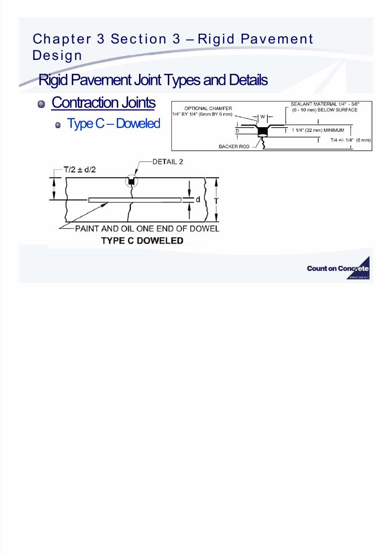
Contraction Joints
Type B –Hinged
Chapt er 3 Sec t ion 3 – Rig id Pavement
8/3/2019 FAARFILD Airport Pavement Design
http://slidepdf.com/reader/full/faarfild-airport-pavement-design 78/109
Rigid Pavement Joint Types and Details
Contraction Joints
Type C –Doweled
Chapt er 3 Sec t ion 3 – Rig id Pavem ent

8/3/2019 FAARFILD Airport Pavement Design
http://slidepdf.com/reader/full/faarfild-airport-pavement-design 79/109
Rigid Pavement Joint Types and Details
Contraction Joints
Type D –Dummy
Chapt er 3 Sec t ion 3 – Rig id Pavement

8/3/2019 FAARFILD Airport Pavement Design
http://slidepdf.com/reader/full/faarfild-airport-pavement-design 80/109
Rigid Pavement Joint Types and Details
Construction Joints
Type E –Doweled
Chapt er 3 Sec t ion 3 Rig id Pavem ent

8/3/2019 FAARFILD Airport Pavement Design
http://slidepdf.com/reader/full/faarfild-airport-pavement-design 81/109
DesignRigid Pavement Joint Types and Details
Beveled Joint Detail
Intended to reduce chipping and spalling attributed to
snow plows

8/3/2019 FAARFILD Airport Pavement Design
http://slidepdf.com/reader/full/faarfild-airport-pavement-design 82/109
Chapt er 5 –Pavem ent s For L ight Ai rc raf t

8/3/2019 FAARFILD Airport Pavement Design
http://slidepdf.com/reader/full/faarfild-airport-pavement-design 83/109
Rigid Pavement –Joint Steel For Rigid Pavement
TABLE 3-17. DIMENSIONS AND SPACING OF STEEL DOWELS
c ness o a ame er eng pac ng
6-7 in (152-178 mm) ¾ in1 (20 mm) 18 in (460 mm) 12 in (305 mm)
7.5-12 in (191-305 mm) 1 in1 (25 mm) 19 in (480 mm) 12 in (305 mm)
. - n - mm n mm n mm n mm
16.5-20 in (419-58 mm) 1 ½ in1 (40 mm) 20 in (510 mm) 18 in (460 m)
20.5-24 in (521-610 mm) 2 in1 (50 mm) 24 in (610 mm) 18 in (460 mm)
1 - -.each end with a tight-fitting plastic cap or mortar mix.

8/3/2019 FAARFILD Airport Pavement Design
http://slidepdf.com/reader/full/faarfild-airport-pavement-design 84/109
Chapt er 3 Sec t ion 3 – Rig id Pavement
8/3/2019 FAARFILD Airport Pavement Design
http://slidepdf.com/reader/full/faarfild-airport-pavement-design 85/109
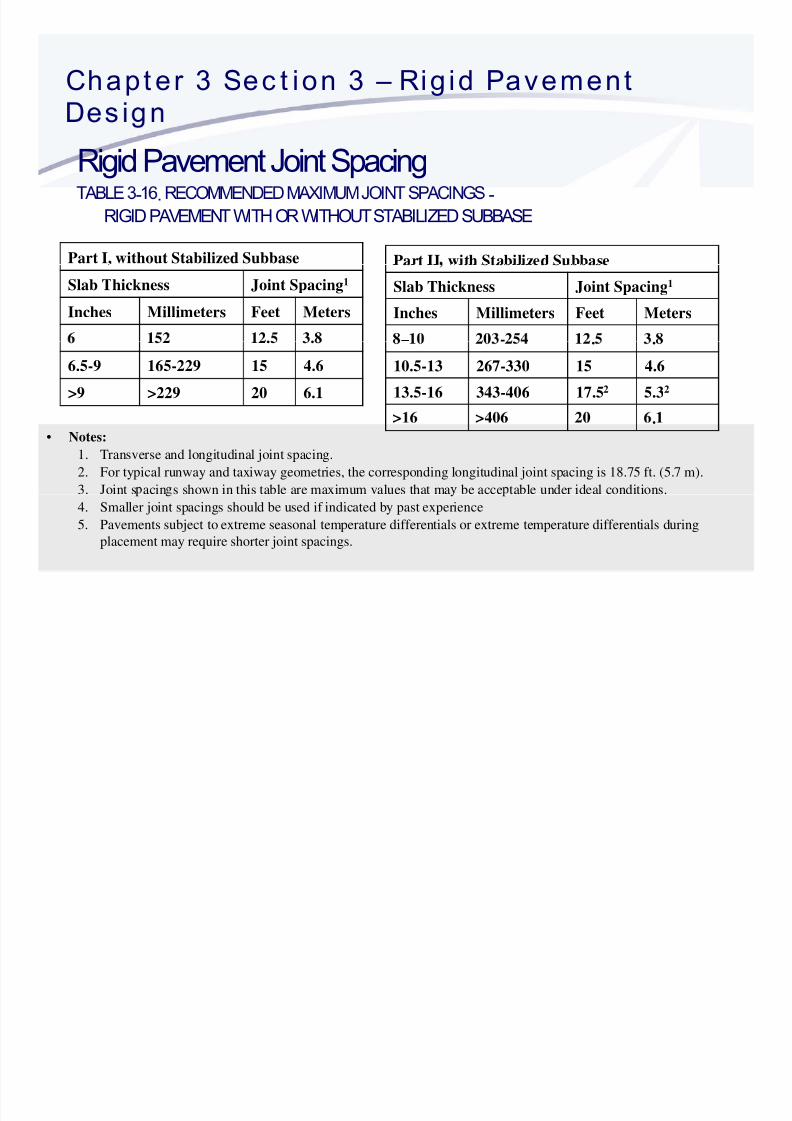
Rigid Pavement Joint Spacing- . -
RIGID PAVEMENT WITH OR WITHOUT STABILIZED SUBBASE
Part I, without Stabilized Subbase Part II with Stabilized Subbase
Slab Thickness Joint Spacing1
Inches Millimeters Feet Meters
Slab Thickness Joint Spacing1
Inches Millimeters Feet Meters
– -6.5-9 165-229 15 4.6
>9 >229 20 6.1
. .10.5-13 267-330 15 4.6
13.5-16 343-406 17.52 5.32
• Notes:
1. Transverse and longitudinal joint spacing.
2. For typical runway and taxiway geometries, the corresponding longitudinal joint spacing is 18.75 ft. (5.7 m).
3. Joint s acin s shown in this table are maximum values that ma be acce table under ideal conditions.
.
4. Smaller joint spacings should be used if indicated by past experience
5. Pavements subject to extreme seasonal temperature differentials or extreme temperature differentials during
placement may require shorter joint spacings.
Chapt er 3 Sec t ion 3 – Rig id Pavement
Desi n
8/3/2019 FAARFILD Airport Pavement Design
http://slidepdf.com/reader/full/faarfild-airport-pavement-design 86/109
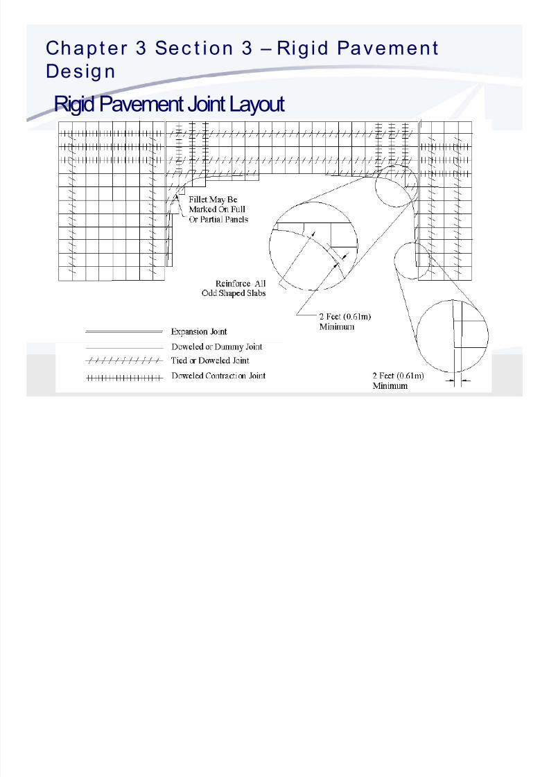
Rigid Pavement Joint Layout
CHAPTER4

8/3/2019 FAARFILD Airport Pavement Design
http://slidepdf.com/reader/full/faarfild-airport-pavement-design 87/109
CHAPTER 4
RECONSTRUCTION
Chapt er 4 – Ai rpor t Pavement Over lays .

8/3/2019 FAARFILD Airport Pavement Design
http://slidepdf.com/reader/full/faarfild-airport-pavement-design 88/109
OVERLAY TYPES
RigidPCC over existing flexible pavement (whitetopping)
PCC bonded to existing PCC
PCC unbondedto existing PCC
e e e par a y on e
xHot Mix Asphalt over existing flexible pavement
Chapt er 4 – Ai rpor t Pavement Over lays .

8/3/2019 FAARFILD Airport Pavement Design
http://slidepdf.com/reader/full/faarfild-airport-pavement-design 89/109
Overlay design requires the FAARFIELD program
Input variables include:
Existing pavement structure
Including material properties and traffic requirements
Existing pavement condition
Rigid –use Structural Condition Index (SCI)
Flexible – requires engineering judgment

8/3/2019 FAARFILD Airport Pavement Design
http://slidepdf.com/reader/full/faarfild-airport-pavement-design 90/109
Chapt er 4 – Ai rpor t Pavement Over lays .

8/3/2019 FAARFILD Airport Pavement Design
http://slidepdf.com/reader/full/faarfild-airport-pavement-design 91/109
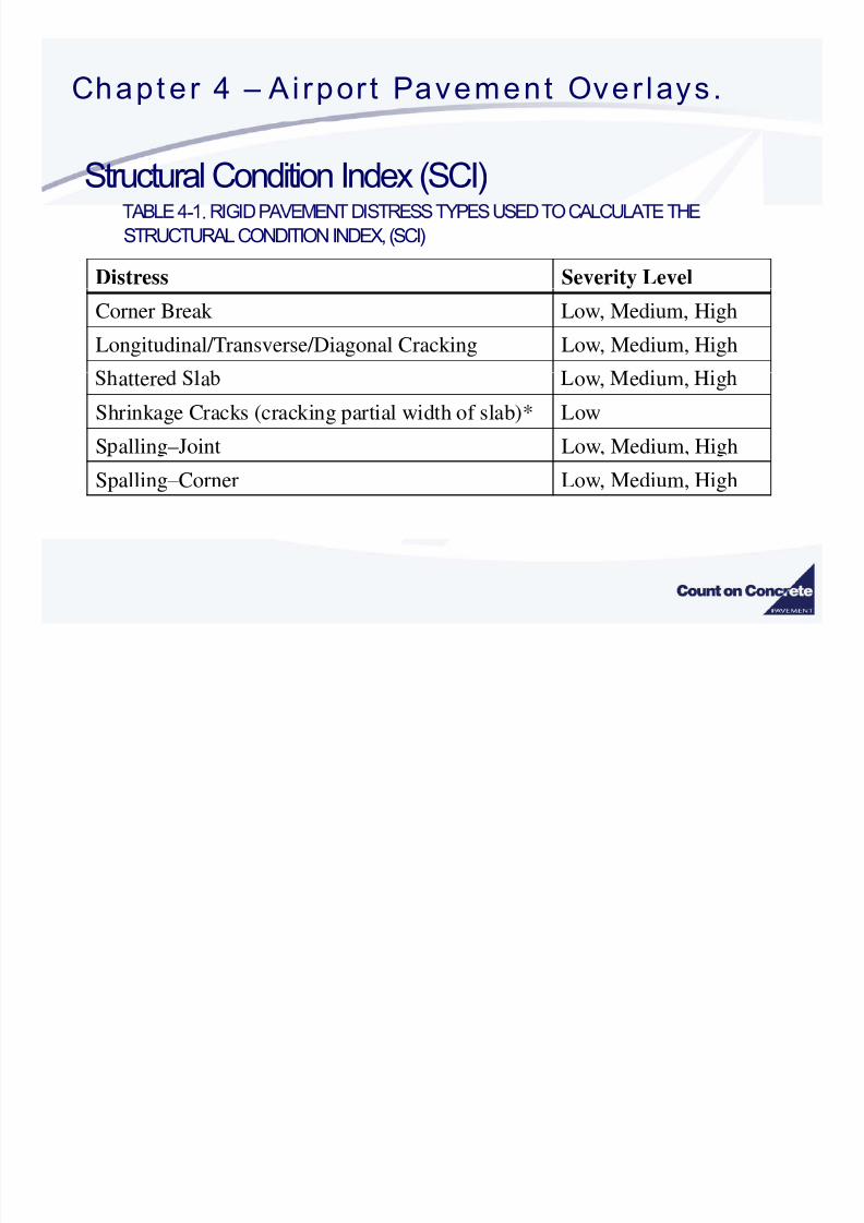
Structural Condition Index (SCI)
SCI = 80 FAA definition of structural failure
50% of slabs with structural crack
Pavement with an SCI = 80 and no durability issues
.Pavement with SCI > 80 but with durability issues can
.
8/3/2019 FAARFILD Airport Pavement Design
http://slidepdf.com/reader/full/faarfild-airport-pavement-design 92/109
Chapt er 4 – Ai rpor t Pavement Over lays .

8/3/2019 FAARFILD Airport Pavement Design
http://slidepdf.com/reader/full/faarfild-airport-pavement-design 93/109
Cumulative Damage Factor Used (CDFU)
SCI = 100 when there is no visible distress contributing
to reduction in SCI ( no structural distress types)Condition of existing pavement described by CDFU
Chapt er 4 – Ai rpor t Pavement Over lays .

8/3/2019 FAARFILD Airport Pavement Design
http://slidepdf.com/reader/full/faarfild-airport-pavement-design 94/109
Cumulative Damage Factor Used (CDFU)=
10080<SCI<100100 % CDFU
CDFU <
80
100
x ( S C I )
STBS
AGBS
I n d e x
40
60
a l C o n d i t i o n I n d distresses
(cracks)
a l
C o n d i t i o
( S C I )
0
20
S
t r u c t u
S t r u c t u
Log Coverages (n )LOG SCALE – COVERAGES
Chapt er 4 – Ai rpor t Pavement Over lays .
C l ti D F t U d(CDFU)

8/3/2019 FAARFILD Airport Pavement Design
http://slidepdf.com/reader/full/faarfild-airport-pavement-design 95/109
Cumulative Damage Factor Used (CDFU)CDFU defines amount of structural l ife used
For structures with aggregate base
LU = number of years of operation of the existing pavement until overlay
LD = design life of the existing pavement in years
mo es s re a ons p or s a ze su ase o re ecimproved performance
Chapt er 4 – Ai rpor t Pavement Over lays .

8/3/2019 FAARFILD Airport Pavement Design
http://slidepdf.com/reader/full/faarfild-airport-pavement-design 96/109
Overlay on Rubblized Concrete Pavement
Design process is similar to New PCC
Rubblized PCC layer is available in FAARFIELDRecommended modulus values 200,000 to 400,000 psi
Thinner PCC layers warrant lower modulus values
Slab Thickness (inches) Moduli (ksi)
6 to 8 100 – 135
– -
> 14 235 - 400

8/3/2019 FAARFILD Airport Pavement Design
http://slidepdf.com/reader/full/faarfild-airport-pavement-design 97/109
Chapt er 5
Pavem ent s fo r Ligh t A i rc ra f t
Chapt er 5 –Pavem ent s For L ight Ai rc raf t
P t d i f i l i hi l th 30000 lb

8/3/2019 FAARFILD Airport Pavement Design
http://slidepdf.com/reader/full/faarfild-airport-pavement-design 98/109
Pavement design for airplanes weighing less than 30,000 lbs
–
FAARFIELD
– Aggregate -Turf pavement
Chapt er 5 –Pavem ent s For L ight Ai rc raf t
1400000

8/3/2019 FAARFILD Airport Pavement Design
http://slidepdf.com/reader/full/faarfild-airport-pavement-design 99/109
1200000198 total air lanes in FAARFIELD
1000000
h t
50 airplanes < 30,000 lbs
67 airplanes < 60,000 lbs
600000
800000
r o s s W e i
79 airplanes < 100,000 lbs
400000
0
- 1 . 5 7
A - 3 2
3 5 0 P
r - 4 1 4
h l - 1 0
B 2 0 0
t - 4 0 0
h l - 2 0
V I / V I I
r - 8 0 0
- 2 1 5
h l - 4 5
L - 5 0
h l - 6 0
- 1 5 C
- G - I V
- 1 0 0
0 L P
- 5 0 0
- 1 5 0
- 7 0 0
0 E R
B B J 2
0 s t d
1 5 4 B
- 3 0 0
2 S B
3 / 7 3
0 s t d
0 E R
I L 8 6
0 o p t
B e l l y
B e l l y
0 s t d
0 E R
0 0 L R
0 s t d
B e l l y
0 E R
- 2 2 5
S W L
C h k . S i x -
M a l i b u - P A - 4 6 -
C h a n c e l l o
S n g l W
S u p e r K i n g A i r -
B e e c h J e
S n g l W
C i t a t i o n -
H a w k e
C a n a d a i r - C
S n g l W S
D u a l W
G u l f s t r e a m
D u a l T a
A d v . B 7 3 7 - 2
B 7 3
D u a l T a
B 7 3
M D 9 0 - 3
B 7 3 7
A 3 2 1 - 2
T U
B 7 5
A 3 0 0 - B
D C 8 -
A 3 0 0 - 6
B 7 6 7 - 3 0
A 3 3 0 - 3 0
A 3 4 0 - 2 0 0 s t d
D C 1 0 - 3 0 / 4 0
A 3 4 0 - 3
B 7 7 7 - 2 0
B 7 7 7 - 2
A 3 4 0 - 5
A 3 4 0 - 5 0 0 o p t
B 7 4 7 - 4 A
Aircraft in FAARFIELD Internal Library
Chapt er 5 –Pavem ent s For L ight Ai rc raf t
Ri id P t i l i hi l th 30000lb

8/3/2019 FAARFILD Airport Pavement Design
http://slidepdf.com/reader/full/faarfild-airport-pavement-design 100/109
Rigid Pavement -- airplanes weighing less than 30,000 lbs
u u
requirements
State Standards permitted for < 30,000 lbs
Minimum thickness = 5 inches < 12,500 lb6 inches 12,501 to 30,000 lbs
Maximum Slab Size
12.5 x 15.0 (ft) (3.8 x 4.6 m)
Chapt er 5 –Pavem ent s For L ight Ai rc raf t
Rigid Pavement Joint Steel For Light Duty Pavement

8/3/2019 FAARFILD Airport Pavement Design
http://slidepdf.com/reader/full/faarfild-airport-pavement-design 101/109
Rigid Pavement –Joint Steel For Light Duty Pavement
All dowels
18 inch Long (460 mm)
12 inch on center (300 mm)
All Tie Bars
No. 4 Deformed Bars
20 inch long (510 mm)
36 inch center (0.9 m)
PAVEMENTDESIGNFOR

8/3/2019 FAARFILD Airport Pavement Design
http://slidepdf.com/reader/full/faarfild-airport-pavement-design 102/109
PAVEMENT DESIGN FOR
Chapter 7 – Pavement Design For Airfield Shoulders
Shoulders are primarily intended to provide

8/3/2019 FAARFILD Airport Pavement Design
http://slidepdf.com/reader/full/faarfild-airport-pavement-design 103/109
Shoulders are primarily intended to provide
roec on rom eroson an genera on o e rs rom e as
Support for airplanes running off the primary pavement
Chapter 7 – Pavement Design For Airfield Shoulders
Shoulder must provide sufficient support for unintentional or

8/3/2019 FAARFILD Airport Pavement Design
http://slidepdf.com/reader/full/faarfild-airport-pavement-design 104/109
p pp
emergency operation of any airplane in the traffic mix.
Must also provide support for emergency and maintenance vehicle
operations
Chapter 7 – Pavement Design For Airfield Shoulders
Minimum section provided by Chapter 7 will not perform in the

8/3/2019 FAARFILD Airport Pavement Design
http://slidepdf.com/reader/full/faarfild-airport-pavement-design 105/109
Minimum section provided by Chapter 7 will not perform in the
Expect considerable movement and possible rutting
Shoulder pavement should be inspected after every
opera on.
Chapter 7 – Pavement Design For Airfield Shoulders
Shoulder Design Procedure

8/3/2019 FAARFILD Airport Pavement Design
http://slidepdf.com/reader/full/faarfild-airport-pavement-design 106/109
Shoulder Design Procedure
Uses FAARFIELD to determine “most demanding
airplane”
Evaluate proposed shoulder section for each airplane
based on 10 operations
Does not use composite traffic mixture
Chapter 7 – Pavement Design For Airfield Shoulders
Shoulder DesignProcedure –Material Requirements

8/3/2019 FAARFILD Airport Pavement Design
http://slidepdf.com/reader/full/faarfild-airport-pavement-design 107/109
Shoulder Design Procedure Material Requirements
Asphalt
P-401/403 or similar local material specifications
Minimum compaction target density –93% max theo.
density
Minimum thickness = 3 inches
P-501 or similar local material specifications
nmum exura s reng = ps
Minimum thickness = 6 inches
Chapter 7 – Pavement Design For Airfield Shoulders
Shoulder Design Procedure –Material Requirements

8/3/2019 FAARFILD Airport Pavement Design
http://slidepdf.com/reader/full/faarfild-airport-pavement-design 108/109
g q
FAA specifications or similar local material specifications
Minimum thickness = 6 inches
Ma be reduced to 4 inch minimum if as halt surface increased b 1 inch
Subbase Material
FAA specifications or similar local material specifications
Expect CBR >20Minimum thickness = 4 inches ractical construction limit

8/3/2019 FAARFILD Airport Pavement Design
http://slidepdf.com/reader/full/faarfild-airport-pavement-design 109/109