airport pavementco-asphalt.com/wp-content/uploads/2017/03/4a-faa-ac5320-6f-march...3 airport...
TRANSCRIPT

Federal AviationAdministration
Airport Pavement
Design and
Evaluation
AC 150/5320-6F
Overview of Changes
Presented by Cindy Hirsch, P.E.
Lead Civil Engineer
FAA Airport Safety & Standards
Northwest Mountain Regional Office
Prepared by Doug Johnson, P.E.
Sr. Civil Engineer - Pavement
FAA Airport Safety & Standards
Airport Engineering AAS-100

Federal AviationAdministration
Overview
• AC 150/5320-6F Airport Pavement Design and
Evaluation
– What’s Different
– FAARFIELD v1.305 vs v1.41
• All Pavement Design in Chapter 3
• Defined ‘regular’ use
• Tables for Minimum Layer Thickness
• Detail Transition Hot Mix Asphalt (HMA) to PCC
• Revised Text and Examples to FAARFIELD v1.41
• Added Appendix on Nondestructive Testing

Federal AviationAdministration
AC 150/5320-6F Organization
3
Chapter Topic
1 Airport Pavements – Their Function and Purpose
2 Soil Investigations and Evaluation
3 Airport Pavement Design
4 Pavement Rehabilitation
5 Pavement Structural Evaluation
6 Pavement Design for Shoulders
Appendix A Soil Characteristics
Appendix B Design of Structures
Appendix C Nondestructive Testing (NDT) using falling-weight type impulse load
devices
Appendix D Reinforced Isolation Joint
Appendix E Related Reading Material

Federal AviationAdministration
AC 150/5320-6F Why Change
• Updated FAARFIELD v1.41
– AC is what issues update
• Just Airport Pavement Design
– no longer a separate chapter on light duty design
since all designs require use of FAARFIELD
• Tables of minimums based upon weight
• More emphasis on evaluation
• step by step examples

Federal AviationAdministration
FAA Pavement Design
• Flexible Pavement
– Layer elastic theory
• Rigid Pavement
– Three-dimensional finite element theory
• Requires FAA computer program
FAARFIELD
– FAA Rigid and Flexible Interactive Elastic Design

Federal AviationAdministration
Selection of Pavement Type
Federal AviationAdministration
Selection of Pavement Type
Remember what you need the pavement
to do:
• Provide a surface to safely operate
aircraft
• Provide one that is smooth, durable,
FOD-free surface, properly drained
and with adequate macro / micro
texture to facilitate control of aircraft

Federal AviationAdministration
Selection of Pavement Type
• It is assumed that all alternatives
will achieve desired result
• Cost Effectiveness Analysis
following OMB A-94

Federal AviationAdministration
Typical Pavement Structure

Federal AviationAdministration
Typical Pavement Structure
• Surface: Surface courses typically include Portland
cement concrete (PCC) and Hot-Mix Asphalt (HMA).
• Base: Base courses generally fall into two classes:
unstabilized and stabilized.
– Unstabilized bases: crushed and uncrushed
aggregates.
– Stabilized bases: crushed and uncrushed
aggregates stabilized with cement or asphalt.
• Subbase: Subbase courses consist of granular
material, which may be unstabilized or stabilized.
• Subgrade: Subgrade consists of natural or modified
soils.

Federal AviationAdministration
Minimum Layer ThicknessFlexible Pavement Structures

Federal AviationAdministration
AC 150/5320-6F
•Lots of information in the footnotes
•When substituting material consider what you
need the material to do

Federal AviationAdministration
Structural Layer Thickness vs
Construction Layer Thickness
•Minimum Construction Lift Thickness
• 4-6 x nMAS
•Gradation 1 3 inches
•Gradation 2 2 inches
•Gradation 3 1-1/2 inches
•Research supports thicker lifts
perform better
Federal AviationAdministration
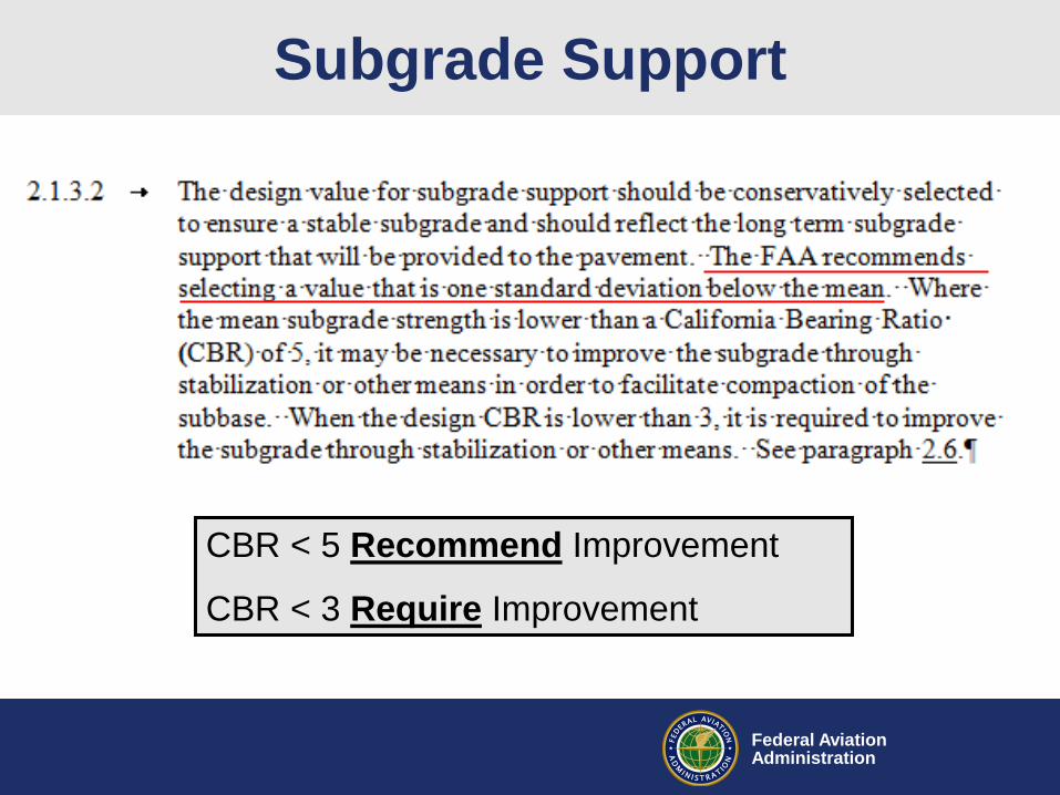
Subgrade Support
CBR < 5 Recommend Improvement
CBR < 3 Require Improvement

Federal AviationAdministration
Subgrade Drainage
•See AC 150/5320-5, Appendix G for
design guidance on subsurface drainage
•Soil k < 20 ft/day: subsurface drainage
layer recommended

Federal AviationAdministration
Chapter 3 Pavement Design
• Design Guidance for Airfield Pavements
– All pavement designs require FAARFIELD
no differentiation between light and aircraft > 30K
– Tables of Minimum Layer Thickness by weight
• Stabilized Base Course
– Full Scale Performance Tests prove that pavements
with stabilized bases have superior performance
– Exception: < 5% Traffic > 100K and < 110K
Federal AviationAdministration
Pavement Life
• Structural Life: Strength to carry loads
• Functional Life: Acceptable Service relative to:
foreign object debris (FOD), Skid Resistance or
roughness
• FAARFIELD Structural Life = Design Life
• Theoretically possible to perform for any period
• Actual Life f(airplane mix, quality of materials
and construction, routine & preventative
maintenance)

Federal AviationAdministration
Pavement LifeTypically, pavements on federally funded FAA projects are designed for a 20 year 1
structural life. Designs for longer periods may be appropriate at airfields where the 2
configuration of the airfield is not expected to change and where future traffic can be 3
forecast with relative confidence beyond 20 years. A longer design life may be 4
appropriate for a runway at a large hub airport where the future aircraft traffic can be 5
forecast and where both the location and size of the runway and taxiways is not 6
anticipated to change. However, when designing a taxiway at a smaller airport it may be 7
more prudent to design for no more than 20 years, than to try to forecast the 8
composition and frequency of future activity. Many airports have significant changes 9
planned, but whether these plans ultimately become reality depends on local economic 10
conditions, (e.g. business upturns or downturns at the fixed base operator (FBO), and the 11
number and composition of based aircraft). Typically a life cycle cost effectiveness 12
analysis is utilized to support design periods other than 20 years. However, fiscal 13
constraints (i.e. funds available) may dictate which pavement section(s) and design life 14
is considered. 15
Longer life not appropriate for all airports

Federal AviationAdministration
No Maintenance = Reduced Life
No pavement will achieve its
design life without routine and
preventative maintenance.

Federal AviationAdministration
Traffic
• In general design for
‘regularly’ using aircraft
• ‘Regular’ use 250 annual departures
(500 operations)
• Sensitivity analysis for occasional or
seasonal– Design Section
– After adjusting structure for rounding and construction
evaluate impact of all aircraft

Federal AviationAdministration
FAARFIELD 1.4 – What’s New?
FAARFIELD 1.4 has:
• Completely revised flexible and rigid failure models
based on newest full-scale test data.
• Improved, more accurate 3D finite element model.
• Completely rewritten concrete overlay design procedure.
• Support for user-defined gear configurations.
• Updated aircraft library aligned with COMFAA 3.0.
• Automated, software-based compaction criteria.
• All data files now stored in document directories.
• Automatically generates PDF design report.

Federal AviationAdministration
Automated Compaction Criteria
Computes compaction control points for rigid & flexible pavements.

Federal AviationAdministration
Compaction Tables
Percent of Max.
Dry Density
Depth from
SurfaceDepth from Top
of Subgrade
Critical Airplane
for Compaction
Modified Proctor (Heavy Load)
Subgrade Compaction Requirements NonCohesive Soil
Percent Maximum Dry Density(%) Depth of compaction
from pavement surface (in) Depth of compaction
from top of subgrade (in) Critical Airplane for Compaction
100 0 - 34 0 - 5 A380 Belly
95 34 - 105 5 - 76 A380 Belly
90 105 - 177 76 - 148 A380 Belly
Cohesive Soil
Percent Maximum Dry Density(%) Depth of compaction
from pavement surface (in) Depth of compaction
from top of subgrade (in) Critical Airplane for Compaction
95 0 - 30 0 - 1 A380 Belly
90 30 - 78 1 - 50 A380 Belly
85 78 - 127 50 - 98 A380 Belly
80 127 - 174 98 - 145 A380 Belly
Subgrade Compaction Notes:
1. Noncohesive soils, for the purpose of determining compaction control, are those with a plasticity index (PI) less than 3.
2. Tabulated values indicate depth ranges within which densities should equal or exceed the indicated percentage of the maximum
dry density as specified in item P-152.
3. Maximum dry density is determined using ASTM Method D 1557.
4. The subgrade in cut areas should have natural densities shown or should (a) be compacted from the surface to achieve the
required densities, (b) be removed and replaced at the densities shown, or (c) when economics and grades permit, be covered with
sufficient select or subbase material so that the uncompacted subgrade is at a depth where the in-place densities are satisfactory.
5. For swelling soils refer to AC 150/5320-6E paragraph 313.

Federal AviationAdministration
Aircraft Libraries
• FAARFIELD & COMFAA
aircraft libraries aligned to
the extent possible.
• All Multigear AC split into
main & belly, but linked for
weight & activity
• Included new aircraft:– A350-900 (Preliminary)
– B747-8
– B787-9
– Embraer Fleet

Federal AviationAdministration
Typical Details (new)
Note: Not shown, but good idea to seal joint
between HMA and PCC

Federal AviationAdministration
Overlay Design
• Reason for Rehabilitation
– Why is pavement ready for rehabilitation
– Structural, material distress, other
• Start with condition assessment
– Complete assessment of pavement materials and
structural integrity
– Thickness, condition, nature and strength of each
layer
• Design must correct reason for
rehabilitation

Federal AviationAdministration
Overlay
• FAARFIELD overlay design
– Layered Elastic and finite element analysis
• Four types of overlay
– HMA overlay of flexible or rigid
– PCC overlay of existing flexible or rigid
• Structural Overlay
– Minimum 3”
– Thicker overlays better long term performance
• Non-Structural Overlay
– Minimum 2”

Federal AviationAdministration
Preparation for Overlay
• Defective areas in base, subbase and
subgrade must be corrected
Federal AviationAdministration
Reporting Weight Bearing Strength
• Aircraft Classification Number /
Pavement Classification Number
(ACN/PCN)
• ICAO Standardized Method
• USA Procedure in AC 150/5335-5C
• FAA Software Program COMFAA & Excel
Spreadsheet to facilitate evaluation
• Report on FAA MasterRecord 5010

Federal AviationAdministration
Chapter 6:
Pavement Design for Shoulders
• Paved shoulders
– Required for Aircraft Group IV and higher
– Recommended Aircraft Group III
• Stabilized Shoulders
– Recommended Aircraft Group I & II
– (Turf, aggregate-turf, soil cement, lime or bituminous
stabilized soil)
• Most Demanding of
– 15 Passes of most demanding airplane or
anticipated traffic from maintenance vehicles

Federal AviationAdministration
Chapter 6:
Pavement Design for Shoulders

Federal AviationAdministration
• No change still allowed
(just rarely done)
– Keel 100% traffic
– Outer edge 1% traffic
– transitions between
Appendix E: Variable Section RW
PI
250'
[76 M]250'
[76 M]
250'
[76 M]
450'
[137 M]
450'
[137 M] A
A
30°
1.
2.
3.
4.
RUNWAY AND TAXIWAY WIDTHS, TRANSVERSE SLOPES, ETC.
SECTIONS BASED ON 150 FT [46 M] RUNWAY WIDTH.
MINIMUM 12 INCHES [30 CM] UP TO 36 INCHES [90 CM] ALLOWABLE.
(DESIGN USING 100% DEPARTURE TRAFFIC)
THICKNESS OF OUTER EDGE THICKNESS, FULL
FULL PAVEMENT THICKNESS
PAVEMENT THICKNESS TAPERS TO REDUCED
(DESIGN USING 1% DEPARTURE TRAFFIC)OUTER EDGE THICKNESS
HIGH-SPEED TAXIWAY EXITS AND SIMILAR(DESIGN USING ARRIVAL TRAFFIC)
PER AC 150/ 5300-13, AIRPORT DESIGN
5. CONSTRUCT A 1.5 INCH [4 CM] DROP BETWEEN PAVED ANDUNPAVED SURFACES.
6. WIDTH OF TAPERS AND TRANSITIONS ON RIGID PAVEMENTS TOBE AN EVEN MULTIPLE OF SLABS, MINIMUM ONE SLAB WIDTH.
PAVEMENT THICKNESS AND/OR HIGH-SPEEDTAXIWAY EXITS AND SIMILAR.
SUBBASE
SUBGRADE
BASE
RUNWAY WIDTHSEE NOTE 4 SEE NOTE 5
SECTION A-A (FOR HMA)
SURFACE, BASE, PCC, ETC. THICKNESS PER AC 150/5320-6.
SLOPESEE NOTE 5
SUBBASE
SUBGRADE
37.5' [11.4 M]
MINIMUM
BASE
NOTES:
25'
[7.6 M]
MINIMUM
25'
[7.6 M]
MINIMUM
25'
[7.6 M]
MINIMUM
25'
[7.6 M]
MINIMUM
25'
[7.6 M]
MINIMUM
25'
[7.6 M]
MINIMUM
18.75' [5.7 M]
MINIMUM
18.75' [5.7 M]
MINIMUM
37.5' [11.4 M]
MINIMUM
18.75' [5.7 M]
MINIMUM
18.75' [5.7 M]
MINIMUM
NOT TO SCALE
TYPICAL PLAN AND CROSS-SECTION FOR RUNWAY PAVEMENT
SLOPE
A-ANOT TO SCALE
LEGEND:
RUNWAY WIDTHSEE NOTE 4
SECTION (FOR PCC)

Federal AviationAdministration
Questions?
Doug Johnson, P.E.
(202) 267-4689
Greg Cline, P.E.
(202) 267-8814