experiment 4
DESCRIPTION
Experiment 4. * Operational Amplifiers * Op-Amp Circuits * Op-Amp Analysis. Operational Amplifiers. Op-Amps are possibly the most versatile linear integrated circuits used in analog electronics. The Op-Amp is not strictly an element; it contains elements, such as resistors and transistors. - PowerPoint PPT PresentationTRANSCRIPT
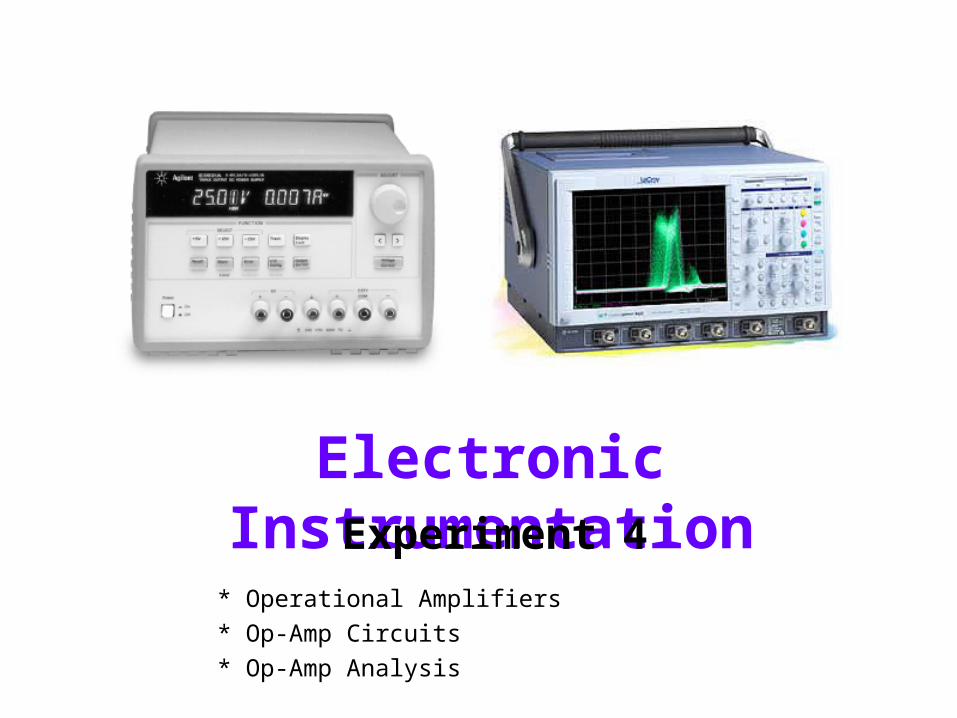
Electronic InstrumentationExperiment 4
* Operational Amplifiers* Op-Amp Circuits* Op-Amp Analysis
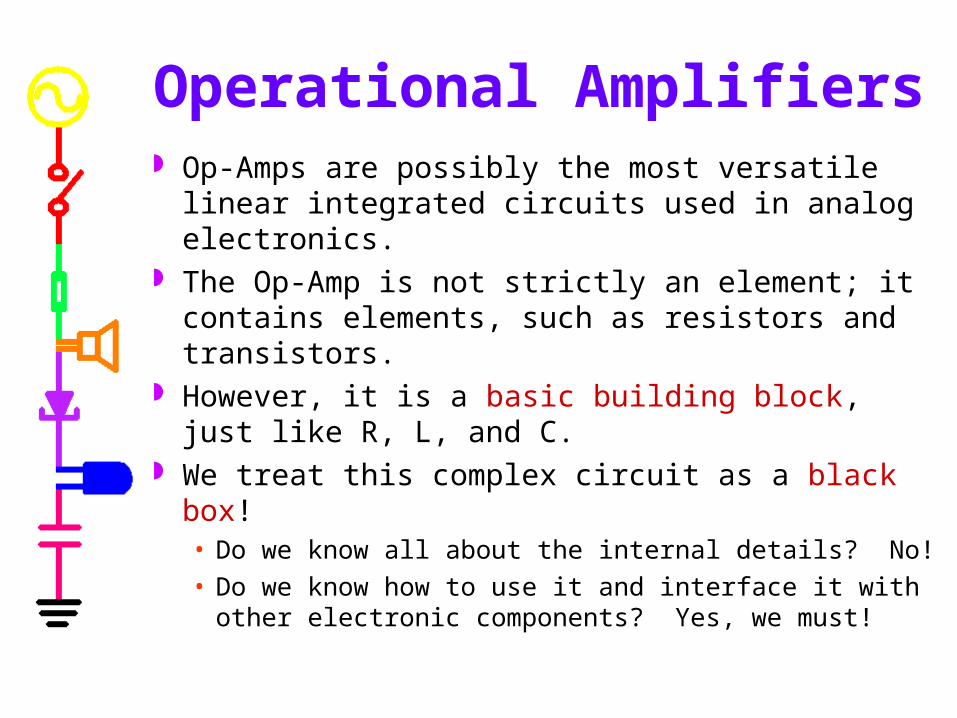
Operational Amplifiers Op-Amps are possibly the most versatile linear
integrated circuits used in analog electronics. The Op-Amp is not strictly an element; it contains
elements, such as resistors and transistors. However, it is a basic building block, just like R,
L, and C. We treat this complex circuit as a black box!
• Do we know all about the internal details? No!• Do we know how to use it and interface it with other
electronic components? Yes, we must!
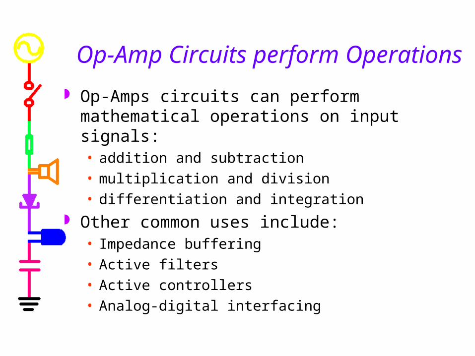
Op-Amp Circuits perform Operations Op-Amps circuits can perform mathematical
operations on input signals:• addition and subtraction• multiplication and division• differentiation and integration
Other common uses include:• Impedance buffering• Active filters• Active controllers• Analog-digital interfacing
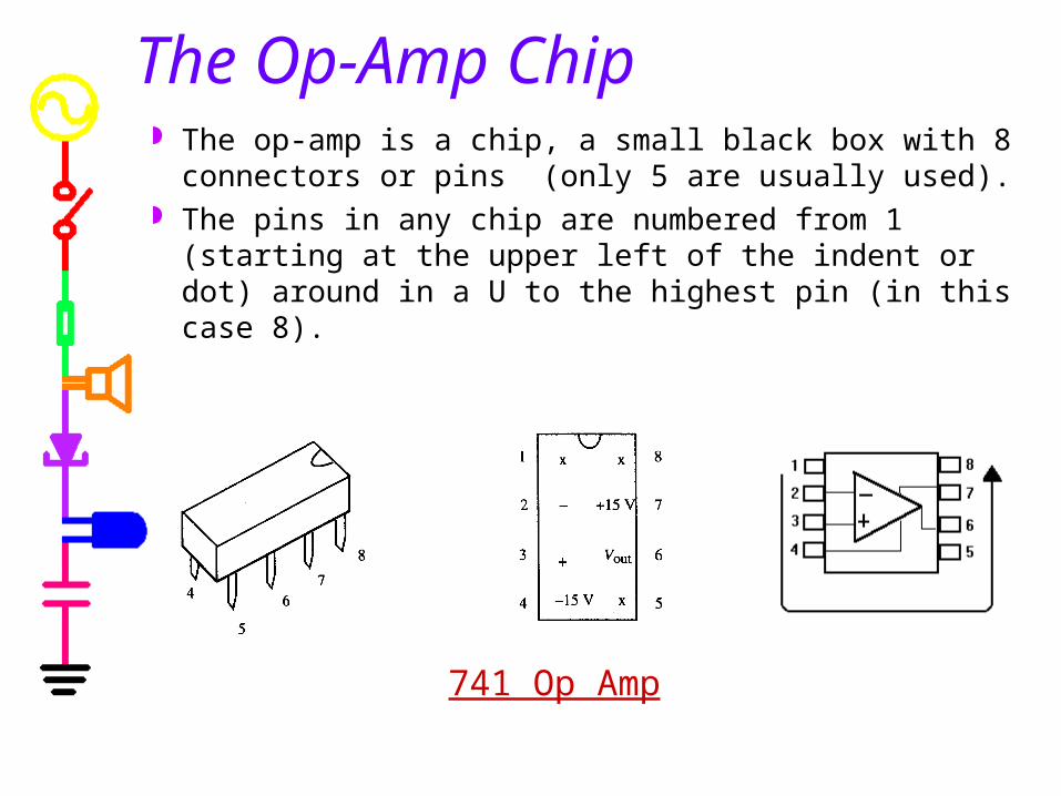
The Op-Amp Chip The op-amp is a chip, a small black box with 8
connectors or pins (only 5 are usually used). The pins in any chip are numbered from 1 (starting
at the upper left of the indent or dot) around in a U to the highest pin (in this case 8).
741 Op Amp

Op-Amp Input and Output The op-amp has two inputs, an inverting input (-) and a
non-inverting input (+), and one output. The output goes positive when the non-inverting input (+)
goes more positive than the inverting (-) input, and vice versa.
The symbols + and – do not mean that that you have to keep one positive with respect to the other; they tell you the relative phase of the output. (Vin=V1-V2)
A fraction of a millivolt between the input terminals will
swing the output over its full range.
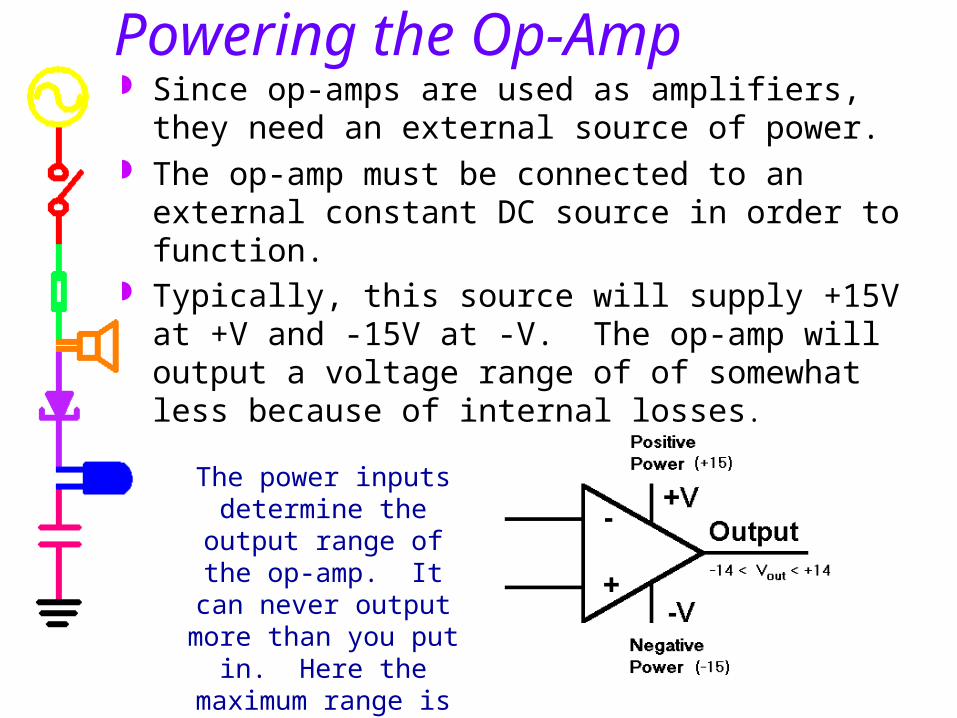
Powering the Op-Amp Since op-amps are used as amplifiers, they need an
external source of power. The op-amp must be connected to an external
constant DC source in order to function. Typically, this source will supply +15V at +V and -
15V at -V. The op-amp will output a voltage range of of somewhat less because of internal losses.
The power inputs determine the output range
of the op-amp. It can never output more than
you put in. Here the maximum range is about
28 volts.
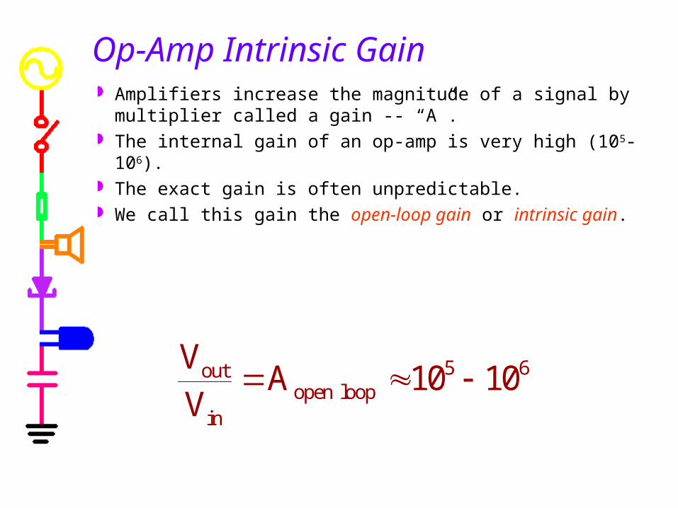
Amplifiers increase the magnitude of a signal by multiplier called a gain -- “A”.
The internal gain of an op-amp is very high (105-106). The exact gain is often unpredictable. We call this gain the open-loop gain or intrinsic gain.
Op-Amp Intrinsic Gain
5 6outopen loop
in
V A 10 10V
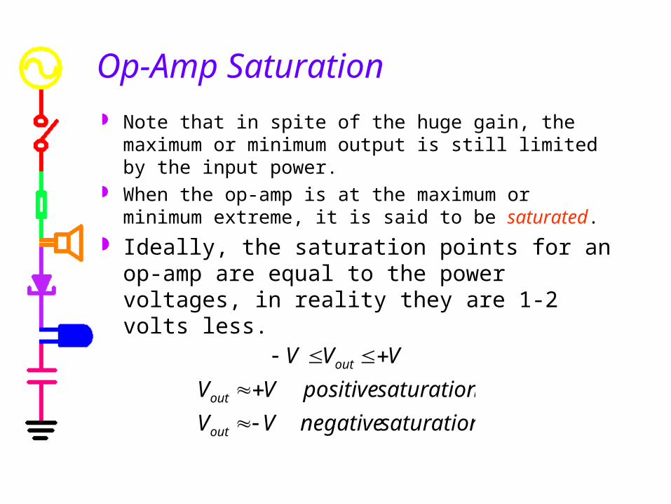
Op-Amp Saturation Note that in spite of the huge gain, the maximum or
minimum output is still limited by the input power. When the op-amp is at the maximum or minimum
extreme, it is said to be saturated. Ideally, the saturation points for an op-amp are
equal to the power voltages, in reality they are 1-2 volts less.
saturationnegativeVVsaturationpositiveVVVVV
out
out
out
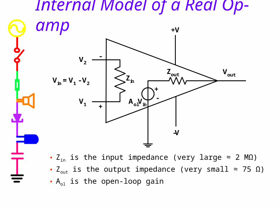
Internal Model of a Real Op-amp
• Zin is the input impedance (very large ≈ 2 MΩ)
• Zout is the output impedance (very small ≈ 75 Ω)
• Aol is the open-loop gain
Vout
V2
+V
-V
-+
V1
Vin = V1 - V2Zin
Zout
+
-
AolVin
Real Op-Amp Characteristics dc-coupled: the op amp can be used with ac and dc
input voltages differential voltage amplifier: the op amp has two
inputs (inverting and non-inverting) single-ended low-resistance output: the op amp has
one output whose voltage is measured with respect to ground. The output looks like a voltage source.
very high input resistance: the op-amp input looks like a load circuit to any circuit connected to its input (ideally 0 current; actually < 1nA)
very high voltage gain: the op-amp will saturate either positive or negative depending on the inputs
Problems using op-amps directly as amplifiers The op-amp intrinsic gain, Aol, can be relied upon to be
very large (1 to 5 million V/V ) but cannot be relied upon to be an accurate stable value.
Using op-amps, we can construct circuits whose performance depends mainly on passive components selected to have accurate and stable values.
As long as Aol is large enough, the behavior of our circuits will depend upon the values of the stable components rather than Aol
Feedback is the process of coupling the op-amp output back into one of the inputs. Understanding feedback is fundamental to understanding op-amp circuits.
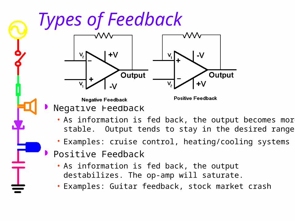
Types of Feedback
Negative Feedback• As information is fed back, the output becomes more stable. Output
tends to stay in the desired range.• Examples: cruise control, heating/cooling systems
Positive Feedback• As information is fed back, the output destabilizes. The op-amp will
saturate.• Examples: Guitar feedback, stock market crash
Op-Amp Circuits use Negative Feedback Negative feedback couples the output back in such a
way as to cancel some of the input. This lowers the amplifier’s gain, but improves:
• Freedom from distortion and nonlinearity• Flatness of frequency response or conformity to some
desired frequency response• Stability and Predictability• Insensitivity to variation in Aol
Amplifiers with negative feedback depend less and less on the open-loop gain and finally depend only on the properties of the feedback network itself.
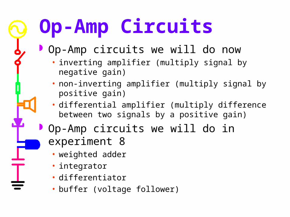
Op-Amp Circuits Op-Amp circuits we will do now
• inverting amplifier (multiply signal by negative gain)• non-inverting amplifier (multiply signal by positive gain)• differential amplifier (multiply difference between two
signals by a positive gain) Op-Amp circuits we will do in experiment 8
• weighted adder• integrator• differentiator• buffer (voltage follower)
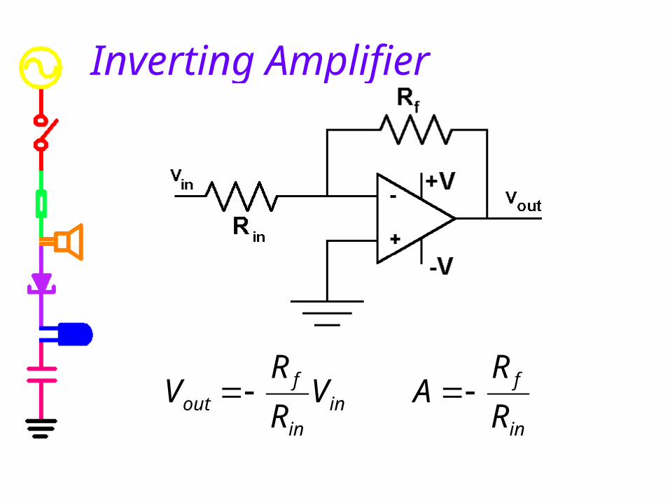
Inverting Amplifier
in
fin
in
fout R
RAV
RR
V
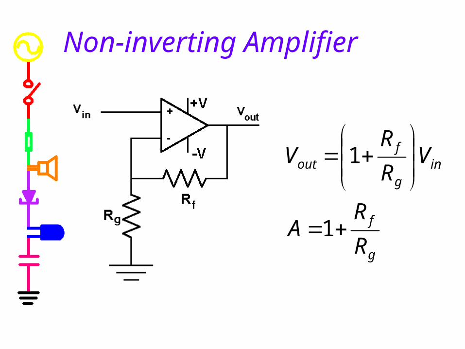
Non-inverting Amplifier
g
f
ing
fout
RR
A
VRR
V
1
1
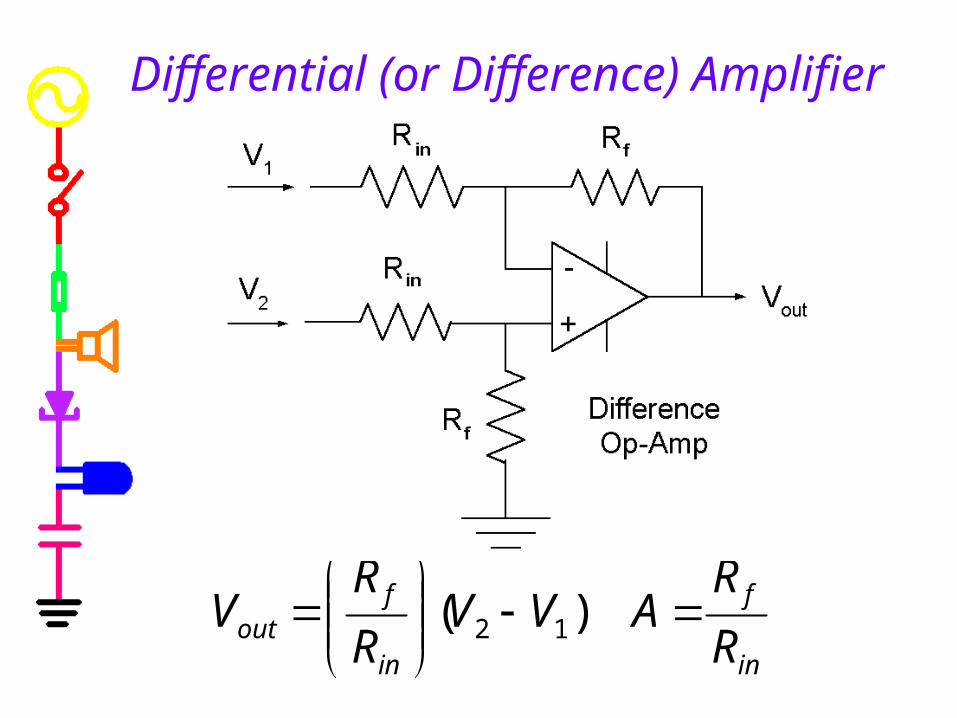
Differential (or Difference) Amplifier
in
f
in
fout R
RAVV
RR
V
)( 12
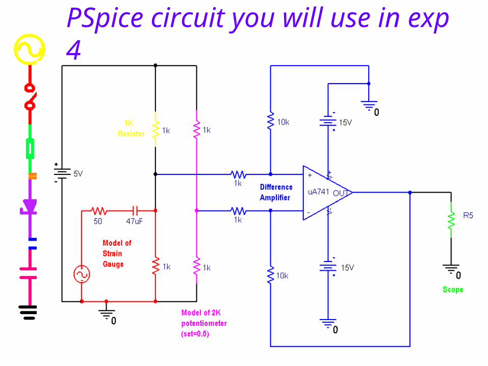
PSpice circuit you will use in exp 4
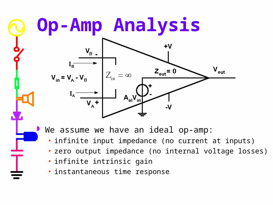
Op-Amp Analysis
We assume we have an ideal op-amp:• infinite input impedance (no current at inputs)• zero output impedance (no internal voltage losses)• infinite intrinsic gain• instantaneous time response
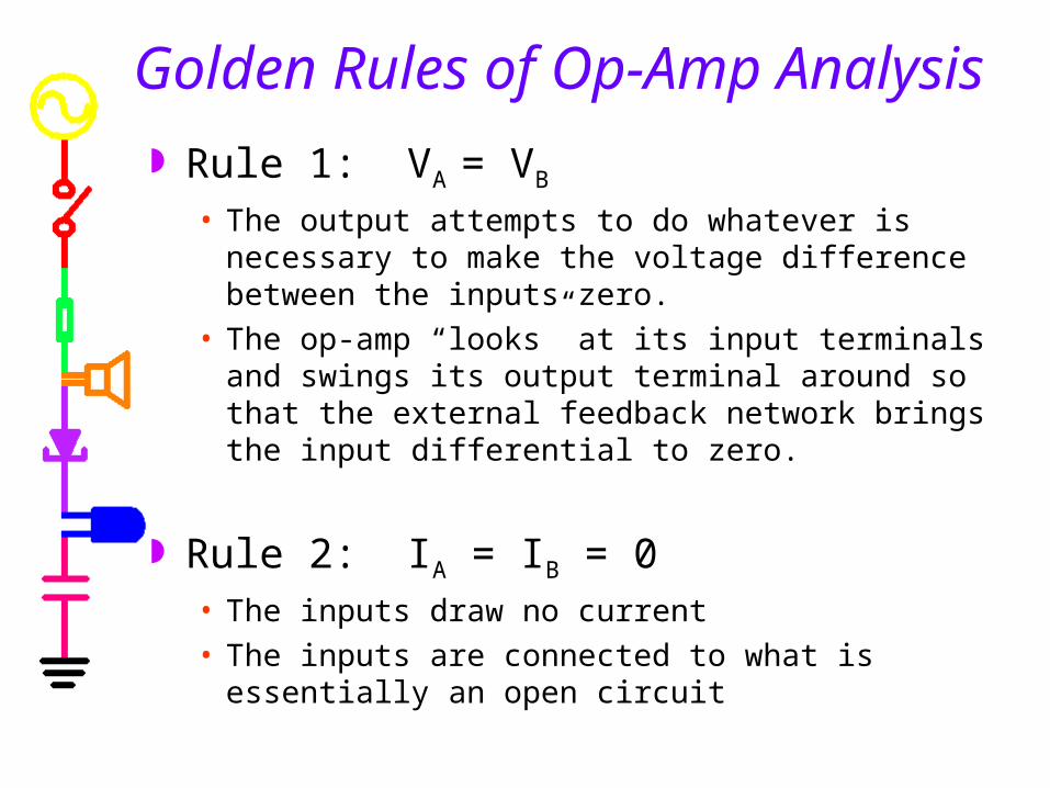
Golden Rules of Op-Amp Analysis Rule 1: VA = VB
• The output attempts to do whatever is necessary to make the voltage difference between the inputs zero.
• The op-amp “looks” at its input terminals and swings its output terminal around so that the external feedback network brings the input differential to zero.
Rule 2: IA = IB = 0• The inputs draw no current• The inputs are connected to what is essentially an
open circuit
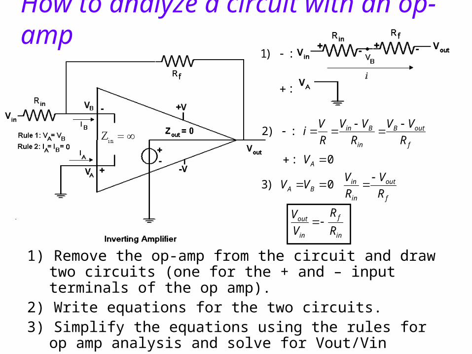
1) Remove the op-amp from the circuit and draw two circuits (one for the + and – input terminals of the op amp).
2) Write equations for the two circuits.3) Simplify the equations using the rules for op amp analysis and
solve for Vout/Vin
How to analyze a circuit with an op-amp
in
f
in
out
f
out
in
inBA
A
f
outB
in
Bin
RR
VV
RV
RVVV
V
RVV
RVV
RVi
0)3
0:
:)2
:
:)1
g
f
in
out
g
gf
in
outout
gf
ginBA
outgf
gB
inA
RR
VV
RRR
VVV
RRR
VVV
VRR
RV
VV
1
)3
:
:)2
::)1
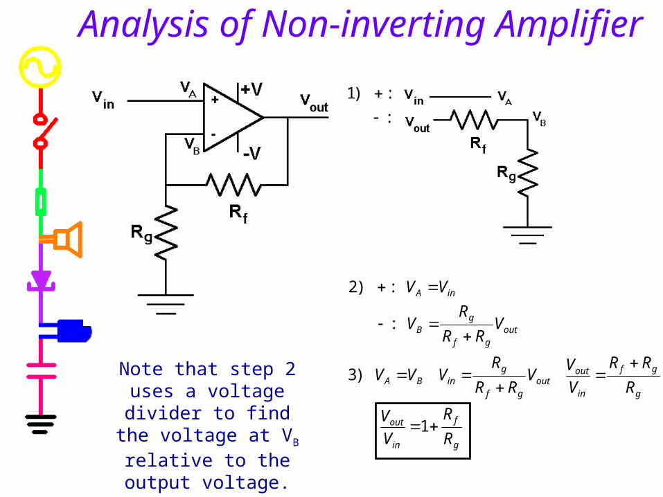
Analysis of Non-inverting Amplifier
Note that step 2 uses a voltage divider to find the voltage at VB relative to
the output voltage.
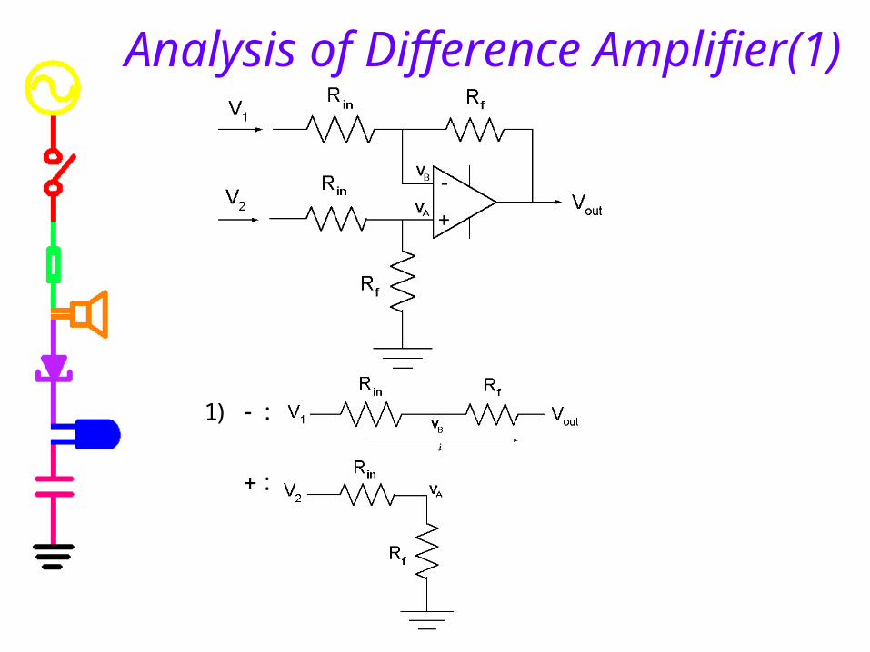
Analysis of Difference Amplifier(1)
:
:)1
in
fout
outinffoutinf
in
inf
f
fin
fBA
outinf
in
inf
fB
fin
inf
fin
outinf
B
fin
f
out
inBB
fin
fA
f
outB
in
B
RR
VVV
VRVRVRVRR
RVRR
RV
RRR
VV
VRR
RVRR
RV
RRRR
RRVRVR
V
RR
RV
RV
VVforsolve
VRR
RV
RVV
RVVi
12
1212
1
11
2
1
:
11:)3
:
:)2
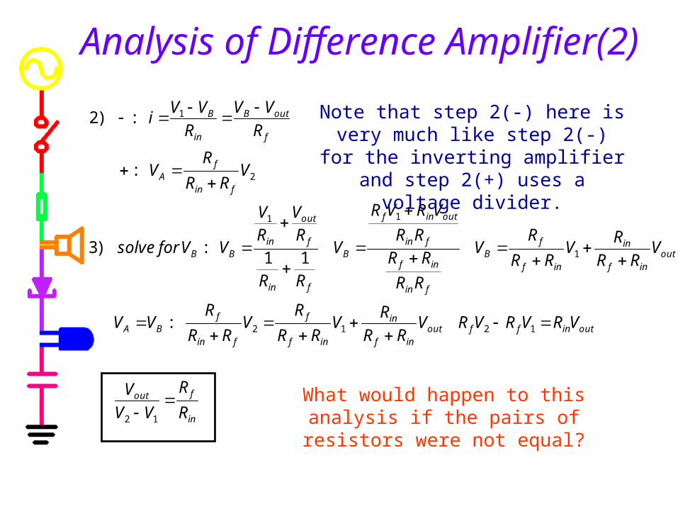
Analysis of Difference Amplifier(2)
Note that step 2(-) here is very much like step 2(-) for the inverting amplifier
and step 2(+) uses a voltage divider.
What would happen to this analysis if the pairs of resistors were not equal?
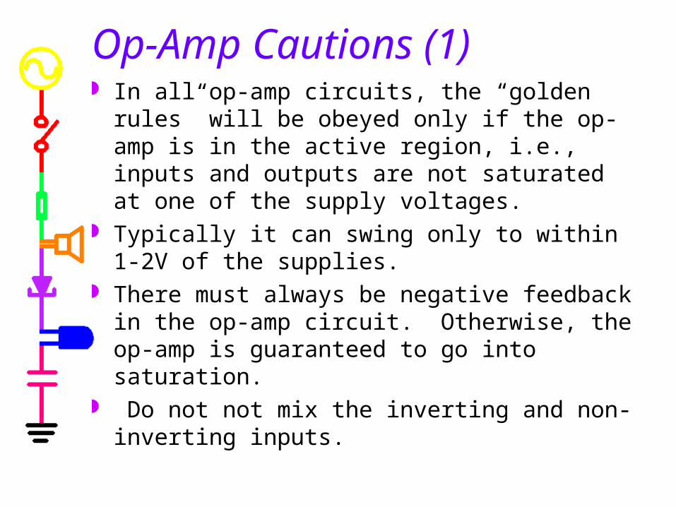
Op-Amp Cautions (1) In all op-amp circuits, the “golden rules” will be
obeyed only if the op-amp is in the active region, i.e., inputs and outputs are not saturated at one of the supply voltages.
Typically it can swing only to within 1-2V of the supplies.
There must always be negative feedback in the op-amp circuit. Otherwise, the op-amp is guaranteed to go into saturation.
Do not not mix the inverting and non-inverting inputs.
Op-Amp Cautions (2) Many op-amps have a relatively small maximum
differential input voltage limit. The maximum voltage difference between the inverting and non-inverting inputs might be limited to as little as 5 volts in either polarity. Breaking this rule will cause large currents to flow, with degradation and destruction of the op-amp.
Note that even though op-amps themselves have a high input impedance and a low output impedance, the input and output impedances of the op-amp circuits you will design are not the same as that of the op-amp.