expansion joint covers - c-sgroup.com 1 2 3 1.wallassembly...
TRANSCRIPT

1
2B
2A
1. Floor AssemblyMin 4-1/2 in. thick reinforced lightweight or normal weight (100-150 pcf ) structural concrete.2. Joint SystemMax width of joint is 4 in. The joint system shall consist of the following:
A. Forming Material* Max 11 in. width of forming material shall be folded in half and packed into joint opening as a permanentform. Forming material to be recessed from top surface of floor as required to accommodate the required thickness of fillmaterial.
BACKER RODMFG INC—ULTRA BLOCK®
B. Fill, Void or Cavity Material* Min 1/2 in. thickness of fill material applied within the joint, flush with top surface of floor.
GENERAL ELECTRIC CO
SILICONE PRODUCTS DIV— Pensil 300 or Pensil 300 S/L Sealants
SPECIFIED TECHNOLOGIES INC— Pensil 300 or Pensil 300 S/L Sealants
*Bearing the UL Classification Mark
UL SYSTEM NO. FF-S-1009
Expansion Joint Covers
To download details, specs & photos visit www.c-sgroup.comFor technical and design assistance call 800-233-8493©Copyright 2008 Construction Specialties, Inc.
Construction Specialties, Inc. reserves the right to make design changes or withdraw any design without notice.
Ultra Block® 1-4” Floor 2-Hour Rated
Assembly Rating - 2 HrJointWidth - 4 In. Max

13
2
1. Floor orWall Assembly— Reinforced lightweight or normal weight (100-150 pcf or 1600-2400 kg/m3) concrete having a min thicknessof 4-1/2 in. (114 mm) at stepped-edges receiving joint cover (Item 3).
2.Mechanical Joint Assembly* — Nom width of joint (at time of installation of joint system) is 1 in. (25mm). The joint system fire barrierconsists of a foil heat shield and an insulation block. The joint system fire barrier shall be installed in accordance with the installationinstructions accompanying the units.
CONSTRUCTION SPECIALTIES INC— RFX-1F
3. Joint Cover—Min 0.030 in. (0.76 mm) thick joint cover formed of aluminum, bronze, stainless steel or galv steel. As an alternate, wherethe linear joint opening is enclosed within a chase wall and is non load bearing, a cover consisting of a creased sheet of min 2 milstainless steel foil secured with 1 in. wide continuous galv steel washer strips along each side of the joint opening may be used. Jointcover anchored to floor slab on each side of joint opening, continuous over entire length of joint, in accordance with themanufacturer's installation instructions.
*Bearing the UL Classification Mark
UL Label †
†APPLIED TO FIRE BARRIER MATERIAL
UL SYSTEM NO. FF-D-0044
Mechanical Joint Assembliesfor Use in Joint Systems SeeUL Fire Resistance Directory
3S65
Expansion Joint Covers
To download details, specs & photos visit www.c-sgroup.comFor technical and design assistance call 800-233-8493©Copyright 2008 Construction Specialties, Inc.
Construction Specialties, Inc. reserves the right to make design changes or withdraw any design without notice.
Reflex® 1” Floor 2-Hour Rated
Assembly Rating - 2 HrNom JointWidth - 1 in.Class II and III Movement Capabilities - 50% Compression or Extension

13
2
1. Floor orWall Assembly— Reinforced lightweight or normal weight (100-150 pcf or 1600-2400 kg/m3) concrete having a min thicknessof 4-1/2 in. (114 mm) at stepped-edges receiving joint cover (Item 3).
2.Mechanical Joint Assembly* — Nom width of joint (at time of installation of joint system) is 2 in. (51mm). The joint system fire barrierconsists of a foil heat shield and an insulation block. The joint system fire barrier shall be installed in accordance with the installationinstructions accompanying the units.
CONSTRUCTION SPECIALTIES INC— RFX-2F (3-HR)
3. Joint Cover—Min 0.030 in. (0.76 mm) thick joint cover formed of aluminum, bronze, stainless steel or galv steel. As an alternate, wherethe linear joint opening is enclosed within a chase wall and is non load bearing, a cover consisting of a creased sheet of min 2 milstainless steel foil secured with 1 in. wide continuous galv steel washer strips along each side of the joint opening may be used. Jointcover anchored to floor slab on each side of joint opening, continuous over entire length of joint, in accordance with themanufacturer's installation instructions.
*Bearing the UL Classification Mark
UL Label †
†APPLIED TO FIRE BARRIER MATERIAL
UL SYSTEM NO. FF-D-0045
Mechanical Joint Assembliesfor Use in Joint Systems SeeUL Fire Resistance Directory
3S65
Expansion Joint Covers
To download details, specs & photos visit www.c-sgroup.comFor technical and design assistance call 800-233-8493©Copyright 2008 Construction Specialties, Inc.
Construction Specialties, Inc. reserves the right to make design changes or withdraw any design without notice.
Reflex® 2” Floor 2-Hour Rated
Assembly Rating - 2 HrNom JointWidth - 2 In.Class II and III Movement Capabilities - 50% Compression or Extension

1
3
2
1. Floor orWall Assembly— Reinforced lightweight or normal weight (100-150 pcf or 1600-2400 kg/m3) concrete having a min thicknessof 4-1/2 in. (114 mm) at stepped-edges receiving joint cover (Item 3).
2.Mechanical Joint Assembly* — Nom width of joint (at time of installation of joint system) is 2 in. (51mm). The joint system fire barrierconsists of a foil heat shield and an insulation block. The joint system fire barrier shall be installed in accordance with the installationinstructions accompanying the units.
` CONSTRUCTION SPECIALTIES INC— RFX-2F (3-HR)
3. Joint Cover—Min 0.030 in. (0.76 mm) thick joint cover formed of aluminum, bronze, stainless steel or galv steel. As an alternate, wherethe linear joint opening is enclosed within a chase wall and is non load bearing, a cover consisting of a creased sheet of min 2 milstainless steel foil secured with 1 in. wide continuous galv steel washer strips along each side of the joint opening may be used. Jointcover anchored to floor slab on each side of joint opening, continuous over entire length of joint, in accordance with themanufacturer's installation instructions.
*Bearing the UL Classification Mark
UL Label †
†APPLIED TO FIRE BARRIER MATERIAL
UL SYSTEM NO. FF-D-0046
Mechanical Joint Assembliesfor Use in Joint Systems SeeUL Fire Resistance Directory
3S65
Expansion Joint Covers
To download details, specs & photos visit www.c-sgroup.comFor technical and design assistance call 800-233-8493©Copyright 2008 Construction Specialties, Inc.
Construction Specialties, Inc. reserves the right to make design changes or withdraw any design without notice.
Reflex® 2” Floor 3-Hour Rated
Assembly Rating - 3 HrNom JointWidth - 2 in.Class II and III Movement Capabilities - 50% Compression or Extension

13
2
1. Floor orWall Assembly— Reinforced lightweight or normal weight (100-150 pcf or 1600-2400 kg/m3) concrete having a min thicknessof 4-1/2 in. (114 mm) at stepped-edges receiving joint cover (Item 3).
2.Mechanical Joint Assembly* — Nom width of joint (at time of installation of joint system) is 3 in. (76mm). The joint system fire barrierconsists of a foil heat shield and an insulation block. The joint system fire barrier shall be installed in accordance with the installationinstructions accompanying the units.
CONSTRUCTION SPECIALTIES INC— RFX-3F
3. Joint Cover—Min 0.030 in. (0.76 mm) thick joint cover formed of aluminum, bronze, stainless steel or galv steel. As an alternate, wherethe linear joint opening is enclosed within a chase wall and is non load bearing, a cover consisting of a creased sheet of min 2 milstainless steel foil secured with 1 in. wide continuous galv steel washer strips along each side of the joint opening may be used. Jointcover anchored to floor slab on each side of joint opening, continuous over entire length of joint, in accordance with themanufacturer's installation instructions.
*Bearing the UL Classification Mark
UL Label †
†APPLIED TO FIRE BARRIER MATERIAL
UL SYSTEM NO. FF-D-1055
Mechanical Joint Assembliesfor Use in Joint Systems SeeUL Fire Resistance Directory
3S65
Expansion Joint Covers
To download details, specs & photos visit www.c-sgroup.comFor technical and design assistance call 800-233-8493©Copyright 2008 Construction Specialties, Inc.
Construction Specialties, Inc. reserves the right to make design changes or withdraw any design without notice.
Reflex® 3” Floor 2-Hour Rated
Assembly Rating - 2 HrNom JointWidth - 3 In.Class II and III Movement Capabilities - 50% Compression or Extension

13
2
1. Floor orWall Assembly— Reinforced lightweight or normal weight (100-150 pcf or 1600-2400 kg/m3) concrete having a min thicknessof 4-1/2 in. (114 mm) at stepped-edges receiving joint cover (Item 3).
2.Mechanical Joint Assembly* — Nom width of joint (at time of installation of joint system) is 4 in. (102mm). The joint system fire barrierconsists of a foil heat shield and an insulation block. The joint system fire barrier shall be installed in accordance with the installationinstructions accompanying the units.
CONSTRUCTION SPECIALTIES INC— RFX-4F
3. Joint Cover—Min 0.030 in. (0.76 mm) thick joint cover formed of aluminum, bronze, stainless steel or galv steel. As an alternate, wherethe linear joint opening is enclosed within a chase wall and is non load bearing, a cover consisting of a creased sheet of min 2 milstainless steel foil secured with 1 in. wide continuous galv steel washer strips along each side of the joint opening may be used. Jointcover anchored to floor slab on each side of joint opening, continuous over entire length of joint, in accordance with themanufacturer's installation instructions.
*Bearing the UL Classification Mark
UL Label †
†APPLIED TO FIRE BARRIER MATERIAL
UL SYSTEM NO. FF-D-1056
Mechanical Joint Assembliesfor Use in Joint Systems SeeUL Fire Resistance Directory
3S65
Expansion Joint Covers
To download details, specs & photos visit www.c-sgroup.comFor technical and design assistance call 800-233-8493©Copyright 2008 Construction Specialties, Inc.
Construction Specialties, Inc. reserves the right to make design changes or withdraw any design without notice.
Reflex® 4” Floor 2-Hour Rated
Assembly Rating - 2 HrNom JointWidth - 4 in.Class II and III Movement Capabilities - 50% Compression or Extension

13
2
3
1.Wall Assembly—The 2 hr fire rated framed gypsum board wall assembly shall be constructed of the materials and in the mannerspecified in the individual U300 or U400 Series Wall and Partition Designs in the UL Fire Resistance Directory and shall include thefollowing construction features:
A. Studs— Steel studs to be min 3-1/2 in. (89 mm) wide and spaced max 24 in. (610 mm) OC. Wood studs to be nom 2 by 4 in.(51 by 102 mm) lumber spaced max 16 in. (406 mm) OC.
B. Gypsum Board*—Gypsum board sheets to be installed to a min total thickness of 1-1/4 in. (32 mm) on each side of wall andon each stud face within joint opening.
2.Mechanical Joint Assembly* — Nom width of joint (at time of installation of joint system) is 1 in. (25 mm). The joint system fire barrierconsists of an insulation block. The joint system fire barrier shall be installed in accordance with the installation instructionsaccompanying the units.
CONSTRUCTION SPECIALTIES INC— RFX-1W
3. Joint Cover—Min 0.030 in. thick joint cover formed of aluminum, bronze, stainless steel or galv steel. Joint covers anchored to eachside of wall on both sides of joint opening, continuous over entire length of joint, in accordance with the manufacturer's installationinstructions. As an alternate, in the area from the finished ceiling to the floor above, a cover consisting of a creased sheet of min 2 milstainless steel foil secured with 1 in. wide continuous galv steel washer strips along each side of the joint opening may be used.
*Bearing the UL Classification MarkUL Label †
†APPLIED TO FIRE BARRIER MATERIAL
UL SYSTEM NO.WW-D-0048
Mechanical Joint Assembliesfor Use in Joint Systems SeeUL Fire Resistance Directory
3S65
Expansion Joint Covers
To download details, specs & photos visit www.c-sgroup.comFor technical and design assistance call 800-233-8493©Copyright 2008 Construction Specialties, Inc.
Construction Specialties, Inc. reserves the right to make design changes or withdraw any design without notice.
Reflex® 1” Wall 2-Hour Rated
Assembly Rating - 2 HrNom JointWidth - 1 In.Class II and III Movement Capabilities - 50% Compression or Extension

13
23
1.Wall Assembly—Min 6 in. (152 mm) thick lightweight or normal weight (100-150 pcf or 1600-2400 kg/m3) reinforced structuralconcrete. Wall may also be constructed of any UL Classified Concrete Blocks*.
See Concrete Blocks (CAZT) category in the Fire Resistance Directory for names of manufacturers.
2.Mechanical Joint Assembly* — Nom width of joint (at time of installation of joint system) is 1 in. (25 mm). The joint system fire barrierconsists of an insulation block. The joint system fire barrier shall be installed in accordance with the installation instructionsaccompanying the units.
CONSTRUCTION SPECIALTIES INC— RFX-1W
3. Joint Cover—Min 0.030 in. thick joint cover formed of aluminum, bronze, stainless steel or galv steel. Joint covers anchored to eachside of wall on both sides of joint opening, continuous over entire length of joint, in accordance with the manufacturer's installationinstructions. As an alternate, in the area from the finished ceiling to the floor above, a cover consisting of a creased sheet of min 2 milstainless steel foil secured with 1 in. wide continuous galv steel washer strips along each side of the joint opening may be used.
*Bearing the UL Classification Mark
UL Label †
†APPLIED TO FIRE BARRIER MATERIAL
UL SYSTEM NO.WW-D-0049
Mechanical Joint Assembliesfor Use in Joint Systems SeeUL Fire Resistance Directory
3S65
Expansion Joint Covers
To download details, specs & photos visit www.c-sgroup.comFor technical and design assistance call 800-233-8493©Copyright 2008 Construction Specialties, Inc.
Construction Specialties, Inc. reserves the right to make design changes or withdraw any design without notice.
Reflex® 1” Wall 2-Hour Rated
Assembly Rating - 2 HrNom JointWidth - 1 in.Class II and III Movement Capabilities - 50% Compression or Extension

13
2
3
1.Wall Assembly—The 1 hr fire rated framed gypsum wallboard wall assembly shall be constructed of the materials and in the mannerspecified in the individual U300 or U400 Series Wall and Partition Designs in the UL Fire Resistance Directory and shall include thefollowing construction features:
A. Studs— Steel studs to be min 3-1/2 in. (89 mm) wide and spaced max 24 in. (610 mm) OC. Wood studs to be nom 2 by 4 in.(51 by 102 mm) lumber spaced max 16 in. (406 mm) OC.
B. Gypsum Board*—Gypsum board sheets to be installed to a min total thickness of 5/8 in. (16 mm) on each side of wall andon each stud face within joint opening.
2.Mechanical Joint Assembly* — Nom width of joint (at time of installation of joint system) is 1 in. (25 mm). The joint system fire barrierconsists of an insulation block. The joint system fire barrier shall be installed in accordance with the installation instructionsaccompanying the units.
CONSTRUCTION SPECIALTIES INC— RFX-1W
3. Joint Cover—Min 0.030 in. thick joint cover formed of aluminum, bronze, stainless steel or galv steel. Joint covers anchored to eachside of wall on both sides of joint opening, continuous over entire length of joint, in accordance with the manufacturer's installationinstructions. As an alternate, in the area from the finished ceiling to the floor above, a cover consisting of a creased sheet of min 2 milstainless steel foil secured with 1 in. wide continuous galv steel washer strips along each side of the joint opening may be used.
*Bearing the UL Classification Mark
UL Label †
†APPLIED TO FIRE BARRIER MATERIAL
UL SYSTEM NO.WW-D-0059
Mechanical Joint Assembliesfor Use in Joint Systems SeeUL Fire Resistance Directory
3S65
Expansion Joint Covers
To download details, specs & photos visit www.c-sgroup.comFor technical and design assistance call 800-233-8493©Copyright 2008 Construction Specialties, Inc.
Construction Specialties, Inc. reserves the right to make design changes or withdraw any design without notice.
Reflex® 1” Wall 1-Hour Rated
Assembly Rating - 1 HrNom JointWidth - 1 In.Class II and III Movement Capabilities - 50% Compression or Extension

13
2
3
1.Wall Assembly—Min 4-1/2 in. (114 mm) thick lightweight or normal weight (100-150 pcf or 1600-2400 kg/m3) reinforced structuralconcrete. Wall may also be constructed of any UL Classified Concrete Blocks*.
See Concrete Blocks (CAZT) category in the Fire Resistance Directory for names of manufacturers.
2.Mechanical Joint Assembly* — Nom width of joint (at time of installation of joint system) is 1 in. (25 mm). The joint system fire barrierconsists of an insulation block. The joint system fire barrier shall be installed in accordance with the installation instructionsaccompanying the units.
CONSTRUCTION SPECIALTIES INC— RFX-1W
3. Joint Cover—Min 0.030 in. thick joint cover formed of aluminum, bronze, stainless steel or galv steel. Joint covers anchored to eachside of wall on both sides of joint opening, continuous over entire length of joint, in accordance with the manufacturer's installationinstructions. As an alternate, in the area from the finished ceiling to the floor above, a cover consisting of a creased sheet of min 2 milstainless steel foil secured with 1 in. wide continuous galv steel washer strips along each side of the joint opening may be used.
*Bearing the UL Classification Mark
UL Label †
†APPLIED TO FIRE BARRIER MATERIAL
UL SYSTEM NO.WW-D-0060
Mechanical Joint Assembliesfor Use in Joint Systems SeeUL Fire Resistance Directory
3S65
Expansion Joint Covers
To download details, specs & photos visit www.c-sgroup.comFor technical and design assistance call 800-233-8493©Copyright 2008 Construction Specialties, Inc.
Construction Specialties, Inc. reserves the right to make design changes or withdraw any design without notice.
Reflex® 1” Wall 1-Hour Rated
Assembly Rating - 1 HrNom JointWidth - 1 in.Class II and III Movement Capabilities - 50% Compression or Extension

13
23
1.Wall Assembly—The 2 hr fire rated framed gypsum board wall assembly shall be constructed of the materials and in the mannerspecified in the individual U300 or U400 Series Wall and Partition Designs in the UL Fire Resistance Directory and shall include thefollowing construction features:
A. Studs— Steel studs to be min 3-1/2 in. (89 mm) wide and spaced max 24 in. (610 mm) OC. Wood studs to be nom 2 by 4 in.(51 by 102 mm) lumber spaced max 16 in. (406 mm) OC.
B. Gypsum Board*—Gypsum board sheets to be installed to a min total thickness of 1-1/4 in. (32 mm) on each side of wall andon each stud face within joint opening.
2.Mechanical Joint Assembly* — Nom width of joint (at time of installation of joint system) is 2 in. (51 mm). The joint system fire barrierconsists of an insulation block. The joint system fire barrier shall be installed in accordance with the installation instructionsaccompanying the units.
CONSTRUCTION SPECIALTIES INC— RFX-2W
3. Joint Cover—Min 0.030 in. thick joint cover formed of aluminum, bronze, stainless steel or galv steel. Joint covers anchored to eachside of wall on both sides of joint opening, continuous over entire length of joint, in accordance with the manufacturer's installationinstructions. As an alternate, in the area from the finished ceiling to the floor above, a cover consisting of a creased sheet of min 2 milstainless steel foil secured with 1 in. wide continuous galv steel washer strips along each side of the joint opening may be used.
*Bearing the UL Classification MarkUL Label †
†APPLIED TO FIRE BARRIER MATERIAL
UL SYSTEM NO.WW-D-0050
Mechanical Joint Assembliesfor Use in Joint Systems SeeUL Fire Resistance Directory
3S65
Expansion Joint Covers
To download details, specs & photos visit www.c-sgroup.comFor technical and design assistance call 800-233-8493©Copyright 2008 Construction Specialties, Inc.
Construction Specialties, Inc. reserves the right to make design changes or withdraw any design without notice.
Reflex® 2” Wall 2-Hour Rated
Assembly Rating - 2 HrNom JointWidth - 2 In.Class II and III Movement Capabilities - 50% Compression or Extension

13
23
1.Wall Assembly—Min 6 in. (152 mm) thick lightweight or normal weight (100-150 pcf or 1600-2400 kg/m3) reinforced structuralconcrete. Wall may also be constructed of any UL Classified Concrete Blocks*.
See Concrete Blocks (CAZT) category in the Fire Resistance Directory for names of manufacturers.
2.Mechanical Joint Assembly* — Nom width of joint (at time of installation of joint system) is 2 in. (51 mm). The joint system fire barrierconsists of an insulation block. The joint system fire barrier shall be installed in accordance with the installation instructionsaccompanying the units
CONSTRUCTION SPECIALTIES INC— RFX-2W
3. Joint Cover—Min 0.030 in. thick joint cover formed of aluminum, bronze, stainless steel or galv steel. Joint covers anchored to eachside of wall on both sides of joint opening, continuous over entire length of joint, in accordance with the manufacturer's installationinstructions. As an alternate, in the area from the finished ceiling to the floor above, a cover consisting of a creased sheet of min 2 milstainless steel foil secured with 1 in. wide continuous galv steel washer strips along each side of the joint opening may be used.
*Bearing the UL Classification Mark
UL Label †
†APPLIED TO FIRE BARRIER MATERIAL
UL SYSTEM NO.WW-D-0051
Mechanical Joint Assembliesfor Use in Joint Systems SeeUL Fire Resistance Directory
3S65
Expansion Joint Covers
To download details, specs & photos visit www.c-sgroup.comFor technical and design assistance call 800-233-8493©Copyright 2008 Construction Specialties, Inc.
Construction Specialties, Inc. reserves the right to make design changes or withdraw any design without notice.
Reflex® 2” Wall 2-Hour Rated
Assembly Rating - 2 HrNom JointWidth - 2 in.Class II and III Movement Capabilities - 50% Compression or Extension

13
2
3
1.Wall Assembly—The 1 hr fire rated framed gypsum wallboard wall assembly shall be constructed of the materials and in the mannerspecified in the individual U300 or U400 Series Wall and Partition Designs in the UL Fire Resistance Directory and shall include thefollowing construction features:
A. Studs— Steel studs to be min 3-1/2 in. (89 mm) wide and spaced max 24 in. (610 mm) OC. Wood studs to be nom 2 by 4 in.(51 by 102 mm) lumber spaced max 16 in. (406 mm) OC.
B. Gypsum Board*—Gypsum board sheets to be installed to a min total thickness of 5/8 in. (16 mm) on each side of wall andon each stud face within joint opening.
2.Mechanical Joint Assembly* — Nom width of joint (at time of installation of joint system) is 2 in. (51 mm). The joint system fire barrierconsists of an insulation block. The joint system fire barrier shall be installed in accordance with the installation instructionsaccompanying the units.
CONSTRUCTION SPECIALTIES INC— RFX-2W
3. Joint Cover—Min 0.030 in. thick joint cover formed of aluminum, bronze, stainless steel or galv steel. Joint covers anchored to eachside of wall on both sides of joint opening, continuous over entire length of joint, in accordance with the manufacturer's installationinstructions. As an alternate, in the area from the finished ceiling to the floor above, a cover consisting of a creased sheet of min 2 milstainless steel foil secured with 1 in. wide continuous galv steel washer strips along each side of the joint opening may be used.
*Bearing the UL Classification MarkUL Label †
†APPLIED TO FIRE BARRIER MATERIAL
UL SYSTEM NO.WW-D-0061
Mechanical Joint Assembliesfor Use in Joint Systems SeeUL Fire Resistance Directory
3S65
Expansion Joint Covers
To download details, specs & photos visit www.c-sgroup.comFor technical and design assistance call 800-233-8493©Copyright 2008 Construction Specialties, Inc.
Construction Specialties, Inc. reserves the right to make design changes or withdraw any design without notice.
Reflex® 2” Wall 1-Hour Rated
Assembly Rating - 1 HrNom JointWidth - 2 In.Class II and III Movement Capabilities - 50% Compression or Extension

13
23
1.Wall Assembly—Min 4-1/2 in. (114 mm) thick lightweight or normal weight (100-150 pcf or 1600-2400 kg/m3) reinforced structuralconcrete. Wall may also be constructed of any UL Classified Concrete Blocks*.
See Concrete Blocks (CAZT) category in the Fire Resistance Directory for names of manufacturers.
2.Mechanical Joint Assembly* — Nom width of joint (at time of installation of joint system) is 2 in. (51 mm). The joint system fire barrierconsists of an insulation block. The joint system fire barrier shall be installed in accordance with the installation instructionsaccompanying the units
CONSTRUCTION SPECIALTIES INC— RFX-2W (1h)
3. Joint Cover—Min 0.030 in. thick joint cover formed of aluminum, bronze, stainless steel or galv steel. Joint covers anchored to eachside of wall on both sides of joint opening, continuous over entire length of joint, in accordance with the manufacturer's installationinstructions. As an alternate, in the area from the finished ceiling to the floor above, a cover consisting of a creased sheet of min 2 milstainless steel foil secured with 1 in. wide continuous galv steel washer strips along each side of the joint opening may be used.
*Bearing the UL Classification Mark
UL Label †
†APPLIED TO FIRE BARRIER MATERIAL
UL SYSTEM NO.WW-D-0062
Mechanical Joint Assembliesfor Use in Joint Systems SeeUL Fire Resistance Directory
3S65
Expansion Joint Covers
To download details, specs & photos visit www.c-sgroup.comFor technical and design assistance call 800-233-8493©Copyright 2008 Construction Specialties, Inc.
Construction Specialties, Inc. reserves the right to make design changes or withdraw any design without notice.
Reflex® 2” Wall 1-Hour Rated
Assembly Rating - 1 HrNom JointWidth - 2 in.Class II and III Movement Capabilities - 50% Compression or Extension

13
23
1.Wall Assembly—The 2 hr fire rated framed gypsum board wall assembly shall be constructed of the materials and in the mannerspecified in the individual U300, U400 or V400 Series Wall and Partition Designs in the UL Fire Resistance Directory and shall include thefollowing construction features:
A. Studs— Steel studs to be min 3-1/2 in. (89 mm) wide and spaced max 24 in. (610 mm) OC. Wood studs to be nom 2 by 4 in.(51 by 102 mm) lumber spaced max 16 in. (406 mm) OC.
B. Gypsum Board*—Gypsum board sheets to be installed to a min total thickness of 1-1/4 in. (32 mm) on each side of wall andon each stud face within joint opening.
2.Mechanical Joint Assembly*—Nom width of joint (at time of installation of joint system) is 3 in. (76 mm). The joint system fire barrierconsists of an insulation block. The joint system fire barrier shall be installed in accordance with the installation instructionsaccompanying the units.
CONSTRUCTION SPECIALTIES INC— RFX-3WC
3. Joint Cover—Min 0.030 in. (0.76 mm) thick joint cover formed of aluminum, bronze, stainless steel or galv steel. Joint covers anchoredto each side of wall on both sides of joint opening, continuous over entire length of joint, in accordance with the manufacturer'sinstallation instructions. As an alternate, in the area from the finished ceiling to the floor above, a cover consisting of a creased sheet ofmin 2 mil stainless steel foil secured with 1 in. (25 mm) wide continuous galv steel washer strips along each side of the joint opening maybe used.
*Bearing the UL Classification Mark
UL Label †
†APPLIED TO FIRE BARRIER MATERIAL
UL SYSTEM NO.WW-D-1067
Mechanical Joint Assembliesfor Use in Joint Systems SeeUL Fire Resistance Directory
3S65
Expansion Joint Covers
To download details, specs & photos visit www.c-sgroup.comFor technical and design assistance call 800-233-8493©Copyright 2008 Construction Specialties, Inc.
Construction Specialties, Inc. reserves the right to make design changes or withdraw any design without notice.
Reflex® 3” Wall 2-Hour Rated
Assembly Rating - 2 HrNom JointWidth - 3 in.Class II and III Movement Capabilities - 50% Compression or Extension

13
23
1.Wall Assembly—Min 6 in. (152 mm) thick lightweight or normal weight (100-150 pcf or 1600-2400 kg/m3) reinforced structuralconcrete. Wall may also be constructed of any UL Classified Concrete Blocks*.
See Concrete Blocks (CAZT) category in the Fire Resistance Directory for names of manufacturers.
2.Mechanical Joint Assembly*—Nom width of joint (at time of installation of joint system) is 3 in. (76 mm). The joint system fire barrierconsists of an insulation block. The joint system fire barrier shall be installed in accordance with the installation instructionsaccompanying the units.
CONSTRUCTION SPECIALTIES INC— RFX-3WC
3. Joint Cover—Min 0.030 in. (0.76 mm) thick joint cover formed of aluminum, bronze, stainless steel or galv steel. Joint covers anchoredto each side of wall on both sides of joint opening, continuous over entire length of joint, in accordance with the manufacturer'sinstallation instructions. As an alternate, in the area from the finished ceiling to the floor above, a cover consisting of a creased sheet ofmin 2 mil stainless steel foil secured with 1 in. (25 mm) wide continuous galv steel washer strips along each side of the joint opening maybe used.
*Bearing the UL Classification Mark
†APPLIED TO FIRE BARRIER MATERIAL
UL SYSTEM NO.WW-D-1068
Mechanical Joint Assembliesfor Use in Joint Systems SeeUL Fire Resistance Directory
3S65
Expansion Joint Covers
To download details, specs & photos visit www.c-sgroup.comFor technical and design assistance call 800-233-8493©Copyright 2008 Construction Specialties, Inc.
Construction Specialties, Inc. reserves the right to make design changes or withdraw any design without notice.
Reflex® 3” Wall 2-Hour Rated
Assembly Rating - 2 HrNom JointWidth - 3 in.Class II and III Movement Capabilities - 50% Compression or Extension

13
23
1.Wall Assembly—The 2 hr fire rated framed gypsum board wall assembly shall be constructed of the materials and in the mannerspecified in the individual U300, U400 or V400 Series Wall and Partition Designs in the UL Fire Resistance Directory and shall include thefollowing construction features:
A. Studs— Steel studs to be min 3-1/2 in. (89 mm) wide and spaced max 24 in. (610 mm) OC. Wood studs to be nom 2 by 4 in.(51 by 102 mm) lumber spaced max 16 in. (406 mm) OC.
B. Gypsum Board*—Gypsum board sheets to be installed to a min total thickness of 1-1/4 in. (32 mm) on each side of wall andon each stud face within joint opening.
2.Mechanical Joint Assembly*—Nom width of joint (at time of installation of joint system) is 4 in. (102 mm). The joint system firebarrier consists of an insulation block. The joint system fire barrier shall be installed in accordance with the installation instructionsaccompanying the units.
CONSTRUCTION SPECIALTIES INC— RFX-4WC
3. Joint Cover—Min 0.030 in. (0.76 mm) thick joint cover formed of aluminum, bronze, stainless steel or galv steel. Joint covers anchoredto each side of wall on both sides of joint opening, continuous over entire length of joint, in accordance with the manufacturer'sinstallation instructions. As an alternate, in the area from the finished ceiling to the floor above, a cover consisting of a creased sheet ofmin 2 mil stainless steel foil secured with 1 in. (25 mm) wide continuous galv steel washer strips along each side of the joint opening maybe used.
*Bearing the UL Classification Mark
UL Label †
†APPLIED TO FIRE BARRIER MATERIAL
UL SYSTEM NO.WW-D-1071
Mechanical Joint Assembliesfor Use in Joint Systems SeeUL Fire Resistance Directory
3S65
Expansion Joint Covers
To download details, specs & photos visit www.c-sgroup.comFor technical and design assistance call 800-233-8493©Copyright 2008 Construction Specialties, Inc.
Construction Specialties, Inc. reserves the right to make design changes or withdraw any design without notice.
Reflex® 4” Wall 2-Hour Rated
Assembly Rating - 2 HrNom JointWidth - 4 in.Class II and III Movement Capabilities - 50% Compression or Extension

13
2
3
1.Wall Assembly—Min 6 in. (152 mm) thick lightweight or normal weight (100-150 pcf or 1600-2400 kg/m3) reinforced structuralconcrete. Wall may also be constructed of any UL Classified Concrete Blocks*.
See Concrete Blocks (CAZT) category in the Fire Resistance Directory for names of manufacturers.
2.Mechanical Joint Assembly*—Nom width of joint (at time of installation of joint system) is 4 in. (102 mm). The joint system firebarrier consists of an insulation block. The joint system fire barrier shall be installed in accordance with the installation instructionsaccompanying the units.
CONSTRUCTION SPECIALTIES INC— RFX-4WC
3. Joint Cover—Min 0.030 in. (0.76 mm) thick joint cover formed of aluminum, bronze, stainless steel or galv steel. Joint covers anchoredto each side of wall on both sides of joint opening, continuous over entire length of joint, in accordance with the manufacturer'sinstallation instructions. As an alternate, in the area from the finished ceiling to the floor above, a cover consisting of a creased sheet ofmin 2 mil stainless steel foil secured with 1 in. (25 mm) wide continuous galv steel washer strips along each side of the joint opening maybe used.
*Bearing the UL Classification Mark
UL Label †
†APPLIED TO FIRE BARRIER MATERIAL
UL SYSTEM NO.WW-D-1072
Mechanical Joint Assembliesfor Use in Joint Systems SeeUL Fire Resistance Directory
3S65
Expansion Joint Covers
To download details, specs & photos visit www.c-sgroup.comFor technical and design assistance call 800-233-8493©Copyright 2008 Construction Specialties, Inc.
Construction Specialties, Inc. reserves the right to make design changes or withdraw any design without notice.
Reflex® 4” Wall 2-Hour Rated
Assembly Rating - 2 HrNom JointWidth - 4 in.Class II and III Movement Capabilities - 50% Compression or Extension

12C
2B
2A
1. Floor Assembly—Min 4-1/2 in. thick reinforced lightweight or normal weight (100-150 pcf ) structural concrete.
2. Joint System—Max width of joint (at time of installation of joint system) is 1 or 2 in. The joint system is designed toaccommodate a max 50 percent compression, extension or horizontal shear from its installed width. The joint system consists ofthe following:
A.Mechanical Joint Assembly— Fire barrier material encased in corrugated metal and provided with metal flanges. Assemblyto be installed in floor in accordance with the installation instructions provide with the product. The following assemblies areto be used with the different joint sizes:
CONSTRUCTION SPECIALTIES INC
B. Retaining Angles—Min 24 gauge (or heavier) galvanized steel angles installed over metal flanges of joint assembly inaccordance with the installation instructions provided with the product. Angles to extend entire length of joint and are to beattached to floor with min 3/16 in. diam by 1-1/2 in. long masonry anchors spaced a max of 18 in. on center.
C. Joint Cover—Min 0.034 in. thick metallic cover plates secured to top side of floor, continuous over full length of joint. Coverplate attached to floor on one side of opening only with min 1-1/2 in. long masonry anchors spaced a max of 18 in. on center.
*Bearing the UL Classification MarkUL Label †
†APPLIED TO FIRE BARRIER MATERIAL*=NOM JOINTWIDTH
UL SYSTEM NO. FF-D-0051
Nom Joint Width In. Mechanical Joint Designation1 MFX-1F2 MFX-2F
R13368MFX-*F
Expansion Joint Covers
To download details, specs & photos visit www.c-sgroup.comFor technical and design assistance call 800-233-8493©Copyright 2008 Construction Specialties, Inc.
Construction Specialties, Inc. reserves the right to make design changes or withdraw any design without notice.
Multiflex® 1-2” Floor 2-Hour Rated
Assembly Rating - 2 HrNominal JointWidths - 1 and 2 In. (See Item 2A)Class II and IIIMovement Capabilities - 50%Compression, Extension orHorizontal Shear

12C
2B
2A
1. Floor Assembly—Min 4-1/2 in. thick reinforced lightweight or normal weight (100-150 pcf ) structural concrete.
2. Joint System—Max width of joint (at time of installation of joint system) is 3, 4, 5 or 6 in. The joint system is designed toaccommodate a max 50 percent compression, extension or horizontal shear from its installed width. The joint system consists ofthe following:
A.Mechanical Joint Assembly— Fire barrier material encased in corrugated metal and provided with metal flanges. Assemblyto be installed in floor in accordance with the installation instructions provide with the product. The following assemblies areto be used with the different joint sizes:
CONSTRUCTION SPECIALTIES INC
B. Retaining Angles— Stair-stepped 20 gauge (or heavier) galvanized steel angles installed over metal flanges of jointassembly in accordance with the installation instructions provide with the product. Angles to extend entire length of joint andare to be attached to floor with min 3/16 in. diam by 1-1/2 in. long masonry anchors spaced a max of 18 in. on center.
C. Joint Cover—Min 0.034 in. thick metallic cover plates secured to top side of floor, continuous over full length of joint. Coverplate attached to floor on one side of opening only with min 1-1/2 in. long masonry anchors spaced a max of 18 in. on center.
*Bearing the UL Classification MarkUL Label †
†APPLIED TO FIRE BARRIER MATERIAL*=NOM JOINTWIDTH
UL SYSTEM NO. FF-D-1066
Nom Joint Width In. Mechanical Joint Designation3 MFX-3F4 MFX-4F5 MFX-5F6 MFX-6F
R13368MFX-*F
Expansion Joint Covers
To download details, specs & photos visit www.c-sgroup.comFor technical and design assistance call 800-233-8493©Copyright 2008 Construction Specialties, Inc.
Construction Specialties, Inc. reserves the right to make design changes or withdraw any design without notice.
Multiflex® 3-6” Floor 2-Hour Rated
Assembly Rating - 2 HrNominal JointWidths - 3, 4, 5 and 6 In. (See Item 2A)Class II and IIIMovement Capabilities - 50%Compression, Extension orHorizontal Shear

1 2B
2A
1. Floor Assembly—Min 4-1/2 in. thick reinforced lightweight or normal weight (100-150 pcf ) structural concrete.
2. Joint System—Max width of joint (at time of installation of joint system) is 8, 10 or 12 in. The joint system is designed toaccommodate a max 50 percent compression, extension or horizontal shear from its installed width. The joint system consists ofthe following:
A.Mechanical Joint Assembly— Fire barrier material encased in corrugated metal and provided with integral galvanized steelangles. Angles are to be attached to floor with min 3/16 in. diam by 1-1/2 in. long masonry anchors spaced a max of 18 in. oncenter. Assembly to be installed in floor in accordance with the installation instructions provide with the product. Thefollowing assemblies are to be used with the different joint sizes:
CONSTRUCTION SPECIALTIES INC
B. Joint Cover—Min 0.034 in. thick metallic cover plates secured to top side of floor, continuous over full length of joint. Coverplate attached to floor on one side of opening only with min 1-1/2 in. long masonry anchors spaced a max of 18 in. on center.
*Bearing the UL Classification Mark
UL Label †
†APPLIED TO FIRE BARRIER MATERIAL*=NOM JOINTWIDTH
UL SYSTEM NO. FF-D-2009
Nom Joint Width In. Mechanical Joint Designation8 MFX-8F10 MFX-10F12 MFX-12F
R13368MFX-*F
Expansion Joint Covers
To download details, specs & photos visit www.c-sgroup.comFor technical and design assistance call 800-233-8493©Copyright 2008 Construction Specialties, Inc.
Construction Specialties, Inc. reserves the right to make design changes or withdraw any design without notice.
Multiflex® 8-12” Floor 2-Hour Rated
Assembly Rating - 2 HrNominal JointWidths - 8, 10 and 12 In. (See Item 2A)Class II and IIIMovement Capabilities - 50%Compression, Extension orHorizontal Shear

1 2B
2A
1. Floor Assembly—Min 4-1/2 in. thick reinforced lightweight or normal weight (100-150 pcf ) structural concrete.
2. Joint System—Max width of joint (at time of installation of joint system) is 14, 16, 18 or 20 in. The joint system is designed toaccommodate a max 50 percent compression, extension or horizontal shear from its installed width. The joint system consists ofthe following:
A.Mechanical Joint Assembly— Fire barrier material encased in corrugated metal and provided with integral galvanized steelangles. Angles are to be attached to floor with min 3/16 in. diam by 1-1/2 in. long masonry anchors spaced a max of 18 in. oncenter. Assembly to be installed in floor in accordance with the installation instructions provide with the product. The followingassemblies are to be used with the different joint sizes:
CONSTRUCTIONSPECIALTIES INC
B. Joint Cover—Min 0.034 in. thick metallic cover plates secured to top side of floor, continuous over full length of joint. Coverplate attached to floor on one side of opening only with min 1-1/2 in. long masonry anchors spaced a max of 18 in. on center.
*Bearing the UL Classification Mark
UL Label †
†APPLIED TO FIRE BARRIER MATERIAL*=NOM JOINTWIDTH
UL SYSTEM NO. FF-D-3008
Nom Joint Width In. Mechanical Joint Designation14 MFX-14F16 MFX-16F18 MFX-18F20 MFX-20F
R13368MFX-*F
Expansion Joint Covers
To download details, specs & photos visit www.c-sgroup.comFor technical and design assistance call 800-233-8493©Copyright 2008 Construction Specialties, Inc.
Construction Specialties, Inc. reserves the right to make design changes or withdraw any design without notice.
Multiflex® 14-20” Floor 2-Hour Rated
Assembly Rating - 2 HrNominal JointWidths - 14, 16, 18 and 20 In. (See Item 2A)Class II and IIIMovement Capabilities - 50%Compression, Extension orHorizontal Shear

1. Floor Assembly—Min 4-1/2 in. thick reinforced lightweight or normal weight (100-150 pcf ) structural concrete.2.Wall Assembly—Min 4-1/2 in. thick reinforced lightweight or normal weight (100-150 pcf ) structural concrete. Wall may also be
constructed of any UL Classified Concrete Blocks*.See Concrete Blocks (CAZT) category in the Fire Resistance Directory for names of manufacturers.
3. Joint System—Max width of joint (at time of installation of joint system) is 1 or 2 in. The joint system is designed toaccommodate a max 50 percent compression, extension or horizontal shear from its installed width. The joint system consists ofthe following:
A.Mechanical Joint Assembly— Fire barrier material encased in corrugated metal and provided with metal flanges. Assemblyto be installed in floor in accordance with the installation instructions provide with the product. The following assemblies areto be used with the different joint sizes: Nom Joint Width In. Mechanical Joint Designation
CONSTRUCTION SPECIALTIES INC
B. Retaining Angles—Min 24 gauge (or heavier) galvanized steel angles installed over metal flanges of joint assembly inaccordance with the installation instructions provided with the product. Angles to extend entire length of joint and are to beattached to floor with min 3/16 in. diam by 1-1/2 in. long masonry anchors spaced a max of 18 in. on center.
C. Retaining Clips—Min 24 gauge galvanized steel clips installed over metal flanges of joint assembly in accordance with theinstallation instructions provided with the product. Clips to extend length of joint and are to be attached to wall with min3/16 in. diam by 1-1/2 in. long masonry anchors spaced a max of 18 in. on center.
D. Joint Cover—Min 0.034 in. thick metallic cover plates installed on top side of floor, continuous over full length of joint.Cover plate attached only to wall with min 1-1/2 in. long masonry anchors spaced a max of 18 in. on center.
*Bearing the UL Classification Mark UL Label †
†APPLIED TO FIRE BARRIER MATERIAL*=NOM JOINTWIDTH
1
2
3A
3B
3C
3D
UL SYSTEM NO. FW-D-0040
Nom Joint Width In. Mechanical Joint Designation1 MFX-1FW2 MFX-2FW
R13368MFX-*F
Expansion Joint Covers
To download details, specs & photos visit www.c-sgroup.comFor technical and design assistance call 800-233-8493©Copyright 2008 Construction Specialties, Inc.
Construction Specialties, Inc. reserves the right to make design changes or withdraw any design without notice.
Multiflex® 1-2” Floor to Wall 2-Hour Rated
Assembly Rating - 2 HrNominal JointWidths - 1 and 2 In. (See Item 3A)Class II and IIIMovement Capabilities - 50%Compression, Extension orHorizontal Shear
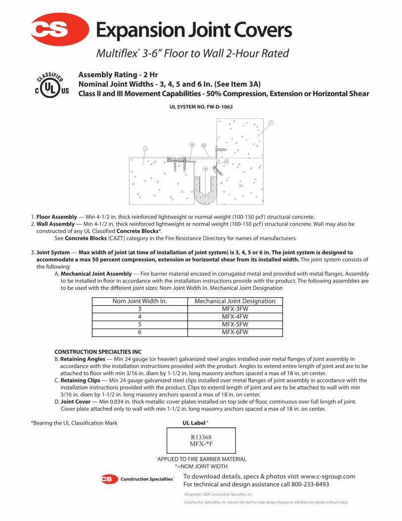
1. Floor Assembly—Min 4-1/2 in. thick reinforced lightweight or normal weight (100-150 pcf ) structural concrete.2.Wall Assembly—Min 4-1/2 in. thick reinforced lightweight or normal weight (100-150 pcf ) structural concrete. Wall may also be
constructed of any UL Classified Concrete Blocks*.See Concrete Blocks (CAZT) category in the Fire Resistance Directory for names of manufacturers.
3. Joint System—Max width of joint (at time of installation of joint system) is 3, 4, 5 or 6 in. The joint system is designed toaccommodate a max 50 percent compression, extension or horizontal shear from its installed width. The joint system consists ofthe following:
A.Mechanical Joint Assembly— Fire barrier material encased in corrugated metal and provided with metal flanges. Assemblyto be installed in floor in accordance with the installation instructions provide with the product. The following assemblies areto be used with the different joint sizes: Nom Joint Width In. Mechanical Joint Designation
CONSTRUCTION SPECIALTIES INCB. Retaining Angles—Min 24 gauge (or heavier) galvanized steel angles installed over metal flanges of joint assembly in
accordance with the installation instructions provided with the product. Angles to extend entire length of joint and are to beattached to floor with min 3/16 in. diam by 1-1/2 in. long masonry anchors spaced a max of 18 in. on center.
C. Retaining Clips—Min 24 gauge galvanized steel clips installed over metal flanges of joint assembly in accordance with theinstallation instructions provided with the product. Clips to extend length of joint and are to be attached to wall with min3/16 in. diam by 1-1/2 in. long masonry anchors spaced a max of 18 in. on center.
D. Joint Cover—Min 0.034 in. thick metallic cover plates installed on top side of floor, continuous over full length of joint.Cover plate attached only to wall with min 1-1/2 in. long masonry anchors spaced a max of 18 in. on center.
*Bearing the UL Classification Mark UL Label †
†APPLIED TO FIRE BARRIER MATERIAL*=NOM JOINTWIDTH
1
2
3A
3B
3C
3D
UL SYSTEM NO. FW-D-1062
R13368MFX-*F
Nom Joint Width In. Mechanical Joint Designation3 MFX-3FW4 MFX-4FW5 MFX-5FW6 MFX-6FW
Expansion Joint Covers
To download details, specs & photos visit www.c-sgroup.comFor technical and design assistance call 800-233-8493©Copyright 2008 Construction Specialties, Inc.
Construction Specialties, Inc. reserves the right to make design changes or withdraw any design without notice.
Multiflex® 3-6” Floor to Wall 2-Hour Rated
Assembly Rating - 2 HrNominal JointWidths - 3, 4, 5 and 6 In. (See Item 3A)Class II and IIIMovement Capabilities - 50%Compression, Extension orHorizontal Shear

1. Floor Assembly—Min 4-1/2 in. thick reinforced lightweight or normal weight (100-150 pcf ) structural concrete.2.Wall Assembly—Min 4-1/2 in. thick reinforced lightweight or normal weight (100-150 pcf ) structural concrete. Wall may also be
constructed of any UL Classified Concrete Blocks*.See Concrete Blocks (CAZT) category in the Fire Resistance Directory for names of manufacturers.
3. Joint System—Max width of joint (at time of installation of joint system) is 8, 10 or 12 in. The joint system is designed toaccommodate a max 50 percent compression, extension or horizontal shear from its installed width. The joint system consists ofthe following:
A.Mechanical Joint Assembly— Fire barrier material encased in corrugated metal and provided with metal flanges. Assemblyto be installed in floor in accordance with the installation instructions provide with the product. The following assemblies areto be used with the different joint sizes: Nom Joint Width In. Mechanical Joint Designation
CONSTRUCTION SPECIALTIES INCB. Retaining Angles—Min 24 gauge (or heavier) galvanized steel angles installed over metal flanges of joint assembly in
accordance with the installation instructions provided with the product. Angles to extend entire length of joint and are to beattached to floor with min 3/16 in. diam by 1-1/2 in. long masonry anchors spaced a max of 18 in. on center.
C. Retaining Clips—Min 24 gauge galvanized steel clips installed over metal flanges of joint assembly in accordance with theinstallation instructions provided with the product. Clips to extend length of joint and are to be attached to wall with min3/16 in. diam by 1-1/2 in. long masonry anchors spaced a max of 18 in. on center.
D. Joint Cover—Min 0.034 in. thick metallic cover plates installed on top side of floor, continuous over full length of joint.Cover plate attached only to wall with min 1-1/2 in. long masonry anchors spaced a max of 18 in. on center.
*Bearing the UL Classification MarkUL Label †
†APPLIED TO FIRE BARRIER MATERIAL*=NOM JOINTWIDTH
1
2
3A
3B
UL SYSTEM NO. FW-D-2004
R13368MFX-*F
Nom Joint Width In. Mechanical Joint Designation8 MFX-8FW10 MFX-10FW12 MFX-12FW
Expansion Joint CoversMultiflex® 8-12” Floor to Wall 2-Hour Rated
Assembly Rating - 2 HrNominal JointWidths - 8, 10 and 12 In. (See Item 3A)Class II and IIIMovement Capabilities - 50%Compression, Extension orHorizontal Shear
To download details, specs & photos visit www.c-sgroup.comFor technical and design assistance call 800-233-8493©Copyright 2008 Construction Specialties, Inc.
Construction Specialties, Inc. reserves the right to make design changes or withdraw any design without notice.

1. Floor Assembly—Min 4-1/2 in. thick reinforced lightweight or normal weight (100-150 pcf ) structural concrete.2.Wall Assembly—Min 4-1/2 in. thick reinforced lightweight or normal weight (100-150 pcf ) structural concrete. Wall may also be
constructed of any UL Classified Concrete Blocks*.See Concrete Blocks (CAZT) category in the Fire Resistance Directory for names of manufacturers.
3. Joint System—Max width of joint (at time of installation of joint system) is 14, 16, 18 or 20 in. The joint system is designed toaccommodate a max 50 percent compression, extension or horizontal shear from its installed width. The joint system consists ofthe following:
A.Mechanical Joint Assembly— Fire barrier material encased in corrugated metal and provided with metal flanges. Assemblyto be installed in floor in accordance with the installation instructions provide with the product. The following assemblies areto be used with the different joint sizes: Nom Joint Width In. Mechanical Joint Designation
CONSTRUCTION SPECIALTIES INCB. Retaining Angles—Min 24 gauge (or heavier) galvanized steel angles installed over metal flanges of joint assembly in
accordance with the installation instructions provided with the product. Angles to extend entire length of joint and are to beattached to floor with min 3/16 in. diam by 1-1/2 in. long masonry anchors spaced a max of 18 in. on center.
C. Retaining Clips—Min 24 gauge galvanized steel clips installed over metal flanges of joint assembly in accordance with theinstallation instructions provided with the product. Clips to extend length of joint and are to be attached to wall with min3/16 in. diam by 1-1/2 in. long masonry anchors spaced a max of 18 in. on center.
D. Joint Cover—Min 0.034 in. thick metallic cover plates installed on top side of floor, continuous over full length of joint.Cover plate attached only to wall with min 1-1/2 in. long masonry anchors spaced a max of 18 in. on center.
*Bearing the UL Classification MarkUL Label †
†APPLIED TO FIRE BARRIER MATERIAL*=NOM JOINTWIDTH
1
2
3A
3B
UL SYSTEM NO. FW-D-3004
R13368MFX-*F
Nom Joint Width In. Mechanical Joint Designation14 MFX-14FW16 MFX-16FW18 MFX-18FW20 MFX-20FW
Expansion Joint CoversMultiflex® 14-20” Floor to Wall 2-Hour Rated
Assembly Rating - 2 HrNominal JointWidths - 14, 16, 18 and 20 In. (See Item 3A)Class II and IIIMovement Capabilities - 50%Compression, Extension orHorizontal Shear
To download details, specs & photos visit www.c-sgroup.comFor technical and design assistance call 800-233-8493©Copyright 2008 Construction Specialties, Inc.
Construction Specialties, Inc. reserves the right to make design changes or withdraw any design without notice.

1.Wall Assembly—The 1 or 2 hr fire rated gypsum wallboard/steel stud wall assembly shall be constructed of the materials and in themanner described in the individual U300 or U400-Series Wall or Partition Design in the UL Fire Resistance Directory and shall include thefollowing construction features:
A. Studs—Wall framing may consist of either wood studs or steel channel studs. Wood studs to consist of nom 2 by 4 in. (orlarger) lumber spaced 16 in. OC. Steel studs to be min 3-5/8 in. wide and spaced max 24 in. OC.B. Gypsum Board*—Wallboard sheets to be installed to a min total thickness of 5/8 or 1-1/4 in. on each side of the wall for a 1or 2 hr rated assemblies, respectively. Additional wallboard sheets installed to a min total thickness of 5/8 or 1-1/4 in. within theopening on each side of opening for a 1 or 2 hr rated assemblies, respectively. The hourly fire rating of the joint system isdependent on the hourly fire rating of the wall.
2. Joint System— width of joint (at time of installation of joint system) is 1 or 2 in. The joint system is designed to accommodate amax 50 percent compression, extension or vertical shear from its installed width. The joint system consists of the following:
A.Mechanical Joint Assembly— Fire barrier material encased in corrugated metal and provided with metal flanges. Assemblyto be installed on either side of wall in accordance with the installation instructions provide with the product. The followingassemblies are to be used with the different joint sizes:
CONSTRUCTION SPECIALTIES INCB. Retaining Angles—Min 2 by 2-1/2 in. 20 gauge (or heavier) galvanized steel angles installed over steel flanges of joint
assembly with 2-1/2 in. leg of angle extending into joint. Angles to extend entire length of joint and are to be attached to wallassembly with min 1-3/4 in. long drywall screws spaced a max of 18 in. on center.
C. Joint Cover —Min 0.034 in. thick metallic cover plates secured to each side of wall, continuous over full height of joint. Coverplates attached to wall on one side of opening only with min 2-1/2 in. long drywall screws spaced a max of 18 in. on center.
*Bearing the UL Classification Mark
UL Label †
†APPLIED TO FIRE BARRIER MATERIAL*=NOM JOINTWIDTH
1A
2C
2A
1B2B
UL SYSTEM NO.WW-D-0052
R13368MFX-*F
Nom Joint Width In. Mechanical Joint Designation1 MFX-1W2 MFX-2W
Expansion Joint CoversMultiflex® 1-2” Wall 1 & 2-Hour Rated
Assembly Rating - 1 and 2 HrNominal JointWidths - 1 and 2 In. (See Item 2A)Class II and IIIMovement Capabilities - 50%Compression, Extension orVertical Shear
To download details, specs & photos visit www.c-sgroup.comFor technical and design assistance call 800-233-8493©Copyright 2008 Construction Specialties, Inc.
Construction Specialties, Inc. reserves the right to make design changes or withdraw any design without notice.

1.Wall Assembly—Min 4-1/2 in. thick reinforced lightweight or normal weight (100-150 pcf ) structural concrete. Wall may also beconstructed of any UL Classified Concrete Blocks*.
See Concrete Blocks (CAZT) category in the Fire Resistance Directory for names of manufacturers.
2. Joint System—Max width of joint (at time of installation of joint system) is 1 or 2 in. The joint system is designed toaccommodate a max 50 percent compression, extension or horizontal shear from its installed width. The joint system consists ofthe following:
A.Mechanical Joint Assembly— Fire barrier material encased in corrugated metal and provided with metal flanges. Assemblyto be installed in floor in accordance with the installation instructions provide with the product. The following assemblies areto be used with the different joint sizes: Nom Joint Width In. Mechanical Joint Designation
CONSTRUCTION SPECIALTIES INCB. Retaining Angles—Min 24 gauge (or heavier) galvanized steel angles installed over metal flanges of joint assembly in
accordance with the installation instructions provided with the product. Angles to extend entire length of joint and are to beattached to floor with min 3/16 in. diam by 1-1/2 in. long masonry anchors spaced a max of 18 in. on center.
C. Retaining Clips—Min 24 gauge galvanized steel clips installed over metal flanges of joint assembly in accordance with theinstallation instructions provided with the product. Clips to extend length of joint and are to be attached to wall with min3/16 in. diam by 1-1/2 in. long masonry anchors spaced a max of 18 in. on center.
D. Joint Cover—Min 0.034 in. thick metallic cover plates installed on top side of floor, continuous over full length of joint.Cover plate attached only to wall with min 1-1/2 in. long masonry anchors spaced a max of 18 in. on center.
*Bearing the UL Classification Mark
UL Label †
†APPLIED TO FIRE BARRIER MATERIAL*=NOM JOINTWIDTH
1
2C
2A
2B
UL SYSTEM NO.WW-D-0053
R13368MFX-*F
Nom Joint Width In. Mechanical Joint Designation1 MFX-1W2 MFX-2W
Expansion Joint CoversMultiflex® 1-2” Wall 2-Hour Rated
Assembly Rating - 2 HrNominal JointWidths - 1 and 2 In. (See Item 2A)Class II and IIIMovement Capabilities - 50%Compression, Extension orVertical Shear
To download details, specs & photos visit www.c-sgroup.comFor technical and design assistance call 800-233-8493©Copyright 2008 Construction Specialties, Inc.
Construction Specialties, Inc. reserves the right to make design changes or withdraw any design without notice.

1.Wall Assembly—The 1 or 2 hr fire rated gypsum wallboard/steel stud wall assembly shall be constructed of the materials and in themanner described in the individual U300 or U400-Series Wall or Partition Design in the UL Fire Resistance Directory and shall include thefollowing construction features:
A. Studs—Wall framing may consist of either wood studs or steel channel studs. Wood studs to consist of nom 2 by 4 in. (orlarger) lumber spaced 16 in. OC. Steel studs to be min 3-5/8 in. wide and spaced max 24 in. OC.B. Gypsum Board*—Wallboard sheets to be installed to a min total thickness of 5/8 or 1-1/4 in. on each side of the wall for a 1or 2 hr rated assemblies, respectively. Additional wallboard sheets installed to a min total thickness of 5/8 or 1-1/4 in. within theopening on each side of opening for a 1 or 2 hr rated assemblies, respectively. The hourly fire rating of the joint system isdependent on the hourly fire rating of the wall.
2. Joint SystemMax— width of joint (at time of installation of joint system) is 3, 4, 5 or 6 in. The joint system is designed toaccommodate a max 50 percent compression, extension or vertical shear from its installed width. The joint system consists of thefollowing:
A.Mechanical Joint Assembly— Fire barrier material encased in corrugated metal and provided with metal flanges. Assemblyto be installed on either side of wall in accordance with the installation instructions provide with the product. The followingassemblies are to be used with the different joint sizes:
CONSTRUCTION SPECIALTIES INCB. Retaining Angles—Min 2-1/2 by 2-1/2 in. 20 gauge (or heavier) galvanized steel angles installed over steel flanges of joint.
Angles to extend entire length of joint and are to be attached to wall assembly with min 1-3/4 in. long drywall screws spaceda max of 18 in. on center.
C. Joint Cover —Min 0.034 in. thick metallic cover plates secured to each side of wall, continuous over full height of joint. Coverplates attached to wall on one side of opening only with min 2-1/2 in. long drywall screws spaced a max of 18 in. on center.
*Bearing the UL Classification Mark UL Label †
†APPLIED TO FIRE BARRIER MATERIAL*=NOM JOINTWIDTH
1
1A
2A
2B2C
UL SYSTEM NO.WW-D-1056
R13368MFX-*F
Nom Joint Width In. Mechanical Joint Designation3 MFX-3W4 MFX-4W5 MFX-5W6 MFX-6W
Expansion Joint CoversMultiflex® 3-6” Wall 1 & 2-Hour Rated
Assembly Rating - 1 and 2 HrNominal JointWidths - 3, 4, 5 and 6 In. (See Item 2A)Class II and IIIMovement Capabilities - 50%Compression, Extension orVertical Shear
To download details, specs & photos visit www.c-sgroup.comFor technical and design assistance call 800-233-8493©Copyright 2008 Construction Specialties, Inc.
Construction Specialties, Inc. reserves the right to make design changes or withdraw any design without notice.

1.Wall Assembly—Min 4-1/2 in. thick reinforced lightweight or normal weight (100-150 pcf ) structural concrete. Wall may also beconstructed of any UL Classified Concrete Blocks*.
See Concrete Blocks (CAZT) category in the Fire Resistance Directory for names of manufacturers.
2. Joint SystemMax— width of joint (at time of installation of joint system) is 3, 4, 5 or 6 in. The joint system is designed toaccommodate a max 50 percent compression, extension or vertical shear from its installed width. The joint system consists of thefollowing:
A.Mechanical Joint Assembly— Fire barrier material encased in corrugated metal and provided with metal flanges. Assemblyto be installed on either side of wall in accordance with the installation instructions provide with the product. The followingassemblies are to be used with the different joint sizes:
CONSTRUCTION SPECIALTIES INCB. Retaining Angles—Min 2-1/2 by 2-1/2 in. 20 gauge (or heavier) galvanized steel angles installed over steel flanges of joint.
Angles to extend entire length of joint and are to be attached to wall assembly with min 1/4 in. diam by 1-1/2 in. longmasonry anchors spaced a max of 18 in. on center.
C. Joint Cover —Min 0.034 in. thick metallic cover plates secured to each side of wall, continuous over full height of joint. Coverplates attached to wall on one side of opening only with min 1/4 in. diam by 1-1/2 in. long masonry anchors spaced a max of18 in. on center.
*Bearing the UL Classification MarkUL Label †
†APPLIED TO FIRE BARRIER MATERIAL*=NOM JOINTWIDTH
1
2A
2B2C
UL SYSTEM NO.WW-D-1057
R13368MFX-*F
Nom Joint Width In. Mechanical Joint Designation3 MFX-3W4 MFX-4W5 MFX-5W6 MFX-6W
Expansion Joint CoversMultiflex® 3-6” Wall 2-Hour Rated
Assembly Rating - 2 HrNominal JointWidths - 3, 4, 5 and 6 In. (See Item 2A)Class II and IIIMovement Capabilities - 50%Compression, Extension orVertical Shear
To download details, specs & photos visit www.c-sgroup.comFor technical and design assistance call 800-233-8493©Copyright 2008 Construction Specialties, Inc.
Construction Specialties, Inc. reserves the right to make design changes or withdraw any design without notice.

1.Wall Assembly—The 1 or 2 hr fire rated gypsum wallboard/steel stud wall assembly shall be constructed of the materials and in themanner described in the individual U300 or U400-Series Wall or Partition Design in the UL Fire Resistance Directory and shall include thefollowing construction features:
A. Studs—Wall framing may consist of either wood studs or steel channel studs. Wood studs to consist of nom 2 by 4 in. (orlarger) lumber spaced 16 in. OC. Steel studs to be min 3-5/8 in. wide and spaced max 24 in. OC.B. Gypsum Board*—Wallboard sheets to be installed to a min total thickness of 5/8 or 1-1/4 in. on each side of the wall for a 1or 2 hr rated assemblies, respectively. Additional wallboard sheets installed to a min total thickness of 5/8 or 1-1/4 in. within theopening on each side of opening for a 1 or 2 hr rated assemblies, respectively. The hourly fire rating of the joint system isdependent on the hourly fire rating of the wall.
2. Joint SystemMax—width of joint (at time of installation of joint system) is 8, 10 or 12 in. The joint system is designed toaccommodate a max 50 percent compression, extension or vertical shear from its installed width. The joint system consists of thefollowing:
A.Mechanical Joint Assembly— Fire barrier material encased in corrugated metal and provided with integral galvanized steelangles. Angles are to be attached to wall assembly with min 1-3/4 in. long drywall screws spaced a max of 18 in. on center.Assembly to be installed on either side of wall in accordance with the installation instructions provide with the product. Thefollowing assemblies are to be used with the different joint sizes:
CONSTRUCTION SPECIALTIES INCB. Joint Cover —Min 0.034 in. thick metallic cover plates secured to each side of wall, continuous over full height of joint. Cover
plates attached to wall on one side of opening only with min 2-1/2 in. long drywall screws spaced a max of 18 in. on center.
*Bearing the UL Classification MarkUL Label †
†APPLIED TO FIRE BARRIER MATERIAL*=NOM JOINTWIDTH
1
1A
2A
2B
UL SYSTEM NO.WW-D-2011
R13368MFX-*F
Nom Joint Width In. Mechanical Joint Designation8 MFX-8W10 MFX-10W12 MFX-12W
Expansion Joint CoversMultiflex® 8-12” Wall 1 & 2-Hour Rated
Assembly Rating - 1 and 2 HrNominal JointWidths - 8, 10 and 12 In. (See Item 2A)Class II and IIIMovement Capabilities - 50%Compression, Extension orVertical Shear
To download details, specs & photos visit www.c-sgroup.comFor technical and design assistance call 800-233-8493©Copyright 2008 Construction Specialties, Inc.
Construction Specialties, Inc. reserves the right to make design changes or withdraw any design without notice.

1.Wall Assembly—Min 4-1/2 in. thick reinforced lightweight or normal weight (100-150 pcf ) structural concrete. Wall may also beconstructed of any UL Classified Concrete Blocks*.
See Concrete Blocks (CAZT) category in the Fire Resistance Directory for names of manufacturers.
2. Joint SystemMax— width of joint (at time of installation of joint system) is 8, 10 or 12 in. The joint system is designed toaccommodate a max 50 percent compression, extension or vertical shear from its installed width. The joint system consists of thefollowing:
A.Mechanical Joint Assembly— Fire barrier material encased in corrugated metal and provided with integral galvanized steelangles. Angles are to be attached to floor with min 1/4 in. diam by 1-1/2 in. long masonry anchors spaced a max of 18 in. oncenter. Assembly to be installed on either side of wall in accordance with the installation instructions provide with the product.The following assemblies are to be used with the different joint sizes:
CONSTRUCTION SPECIALTIES INCB Joint Cover —Min. 0.034 in. thick metallic cover plates secured to each side of wall, continuous over full length of joint. Coverplates attached to wall on one side of Cpening only with min 1/4 in. diam by 1-1/2 in. long mansonry anchors spaced a max of18 in. on center.
*Bearing the UL Classification MarkUL Label †
†APPLIED TO FIRE BARRIER MATERIAL*=NOM JOINTWIDTH
1
2A
2B
UL SYSTEM NO.WW-D-2012
R13368MFX-*F
Nom Joint Width In. Mechanical Joint Designation8 MFX-8W10 MFX-10W12 MFX-12W
Expansion Joint CoversMultiflex® 8-12” Wall 2-Hour Rated
Assembly Rating - 2 HrNominal JointWidths - 8, 10 and 12 In. (See Item 2A)Class II and IIIMovement Capabilities - 50%Compression, Extension orVertical Shear
To download details, specs & photos visit www.c-sgroup.comFor technical and design assistance call 800-233-8493©Copyright 2008 Construction Specialties, Inc.
Construction Specialties, Inc. reserves the right to make design changes or withdraw any design without notice.

1.Wall Assembly—The 1 or 2 hr fire rated gypsum wallboard/steel stud wall assembly shall be constructed of the materials and in themanner described in the individual U300 or U400-Series Wall or Partition Design in the UL Fire Resistance Directory and shall include thefollowing construction features:
A. Studs—Wall framing may consist of either wood studs or steel channel studs. Wood studs to consist of nom 2 by 4 in. (orlarger) lumber spaced 16 in. OC. Steel studs to be min 3-5/8 in. wide and spaced max 24 in. OC.B. Gypsum Board*—Wallboard sheets to be installed to a min total thickness of 5/8 or 1-1/4 in. on each side of the wall for a 1or 2 hr rated assemblies, respectively. Additional wallboard sheets installed to a min total thickness of 5/8 or 1-1/4 in. within theopening on each side of opening for a 1 or 2 hr rated assemblies, respectively. The hourly fire rating of the joint system isdependent on the hourly fire rating of the wall.
2. Joint SystemMax—width of joint (at time of installation of joint system) is 14, 16, 18 or 20 in. The joint system is designed toaccommodate a max 50 percent compression, extension or horizontal shear from its installed width. The joint system consists ofthe following:
A.Mechanical Joint Assembly— Fire barrier material encased in corrugated metal and provided with integral galvanized steelangles. Angles are to be attached to wall assembly with min 1-3/4 in. long drywall screws spaced a max of 18 in. on center. Twoseparate fire barrier assemblies to be installed in floor in accordance with the installation instructions provide with the product.Assembly to be installed on either side of wall in accordance with the installation instructions provide with the product. The firebarrier assemblies' designations are provided with a T or a B to indicate the assemblies' intended position with in the opening.Assemblies with suffix B are installed within the opening first and assemblies with suffix T are installed within the opening overthe B assembly. The following assemblies are to be used with the different joint sizes:
CONSTRUCTION SPECIALTIES INCB. Joint Cover —Min 0.034 in. thick metallic cover plates secured to each side of wall, continuous over full height of joint. Cover
plates attached to wall on one side of opening only with min 2-1/2 in. long drywall screws spaced a max of 18 in. on center.*Bearing the UL Classification Mark
UL Label †
†APPLIED TO FIRE BARRIER MATERIAL*=NOM JOINTWIDTH
1B
1A2A
2B
UL SYSTEM NO.WW-D-3010
R13368MFX-*F
Nom Joint Width In. Mechanical Joint Designation14 MFX-14W16 MFX-16W18 MFX-18W20 MFX-20W
Expansion Joint CoversMultiflex® 14-20” Wall 1 & 2-Hour Rated
Assembly Rating - 1 and 2 HrNominal JointWidths - 14, 16, 18 and 20 In. (See Item 2A)Class II and IIIMovement Capabilities - 50%Compression, Extension orVertical Shear
To download details, specs & photos visit www.c-sgroup.comFor technical and design assistance call 800-233-8493©Copyright 2008 Construction Specialties, Inc.
Construction Specialties, Inc. reserves the right to make design changes or withdraw any design without notice.

1.Wall Assembly—Min 4-1/2 in. thick reinforced lightweight or normal weight (100-150 pcf ) structural concrete. Wall may also beconstructed of any UL Classified Concrete Blocks*.
See Concrete Blocks (CAZT) category in the Fire Resistance Directory for names of manufacturers.
2. Joint SystemMax—width of joint (at time of installation of joint system) is 14, 16, 18 or 20 in. The joint system is designed toaccommodate a max 50 percent compression, extension or horizontal shear from its installed width. The joint system consists ofthe following:
A.Mechanical Joint Assembly— Fire barrier material encased in corrugated metal and provided with integral galvanized steelangles. Angles are to be attached to floor with min 1/4 in. diam by 1-1/2 in. long masonry anchors spaced a max of 18 in. oncenter. Two separate fire barrier assemblies to be installed in floor in accordance with the installation instructions provide withthe product. Assembly to be installed on either side of wall in accordance with the installation instructions provide with theproduct. The fire barrier assemblies' designations are provided with a T or a B to indicate the assemblies' intended position within the opening. Assemblies with suffix B are installed within the opening first and assemblies with suffix T are installed withinthe opening over the B assembly. The following assemblies are to be used with the different joint sizes:
CONSTRUCTIONSPECIALTIES INC
B Joint Cover —Min. 0.034 in. thick metallic cover plates secured to each side of wall, continuous over full length of joint. Coverplates attached to wall on one side of Cpening only with min 1/4 in. diam by 1-1/2 in. long mansonry anchors spaced a max of18 in. on center.
*Bearing the UL Classification MarkUL Label †
†APPLIED TO FIRE BARRIER MATERIAL*=NOM JOINTWIDTH
1
2A
2B
UL SYSTEM NO.WW-D-3011
R13368MFX-*F
Nom Joint Width In. Mechanical Joint Designation14 MFX-14W16 MFX-16W18 MFX-18W20 MFX-20W
Expansion Joint CoversMultiflex® 14-20” Wall 2-Hour Rated
Assembly Rating - 2 HrNominal JointWidths - 14, 16, 18 and 20 In. (See Item 2A)Class II and IIIMovement Capabilities - 50%Compression, Extension orVertical Shear
To download details, specs & photos visit www.c-sgroup.comFor technical and design assistance call 800-233-8493©Copyright 2008 Construction Specialties, Inc.
Construction Specialties, Inc. reserves the right to make design changes or withdraw any design without notice.