evaluation of wearable sensing in mixed reality for …
TRANSCRIPT
EVALUATION OF WEARABLE SENSING IN MIXED REALITY
FOR MOBILE TELEOPERATION
by
Guanhao Fu
A thesis submitted to Johns Hopkins University in conformity with the requirements for
the degree of Master of Science
Baltimore, Maryland
August, 2021
Ⓒ 2021 Guanhao Fu
All rights reserved
ii
Abstract
Teleoperation platforms often require the user to be situated at a fixed location to both visualize
and control the movement of the robot and thus do not provide the operator with much mobility.
One example of such systems is in existing robotic surgery solutions that require the surgeons to
be away from the patient, attached to consoles where their heads must be fixed and their arms
can only move in a limited space. This creates a barrier between physicians and patients that
does not exist in normal surgery. To address this issue, we propose a mobile telesurgery solution
where the surgeons are no longer mechanically limited to control consoles and are able to
teleoperate the robots from the patient bedside, using their arms equipped with wireless sensors
and viewing the endoscope video via optical see-through HMDs. In this work, we develop and
evaluate a mobile telesurgery system based on a Microsoft HoloLens HMD and using three
Inertial Measurement Units (IMUs) mounted on the user's arm. Two IMUs are strapped to the
upper arm and forearm, with the third IMU in a hand-held device. We perform experiments to
compare the proposed system to a conventional telesurgery platform based on the master console
of a da Vinci surgical system.
Primary Reader and Advisor: Peter Kazanzides
Second Reader: Jeremy D. Brown

iii
Contents
Abstract .................................................................................................................................... ii
List of Tables ........................................................................................................................... iv
List of Figures............................................................................................................................v
I. Introduction ...........................................................................................................................1
II. System Description ...............................................................................................................3 A. IMU System Kinematic Model .........................................................................................5 B. User’s Arm Length Calibration .......................................................................................6
III. Experiments ........................................................................................................................7 A. Teleoperation Performance .............................................................................................7
IV. Results ............................................................................................................................... 10 A. Teleoperation results ..................................................................................................... 10
V. Discussion and Conclusions ............................................................................................... 14
Bibliography ............................................................................................................................ 16

iv
List of Tables
Table 1: Completion times for tasks, in seconds 11
Table 2: Mean position errors for tasks, in millimeters 11
Table 3: Mean orientation errors for tasks, in degrees 11
Table 4: Non-collision percentage for straight wire task 11
Table 5: Non-collision percentage for piece-wise wire task 12
Table 6: Performance increase for S-shaped wire task (average across 2 users) 12

v
List of Figures
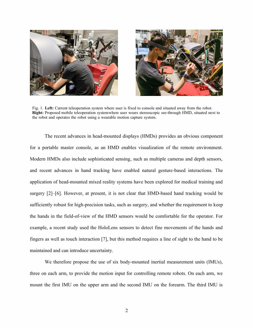
Fig. 1. Left: Current teleoperation system where user is fixed to console and situated away from the robot.
Right: Proposed mobile teleoperation system where user wears stereoscopic see-through HMD, situated next to
the robot and operates the robot using a wearable motion capture system. 2
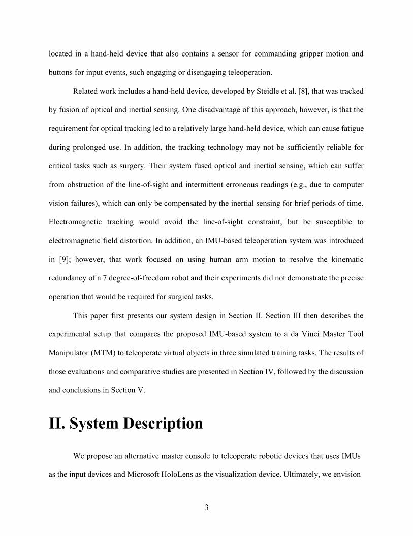
Fig. 2. Experimental Setup: Two wireless IMUs are attached to the upper arm and the forearm. A third IMU
is in a device held by the user (not shown). 5
Fig. 3. Simplified ball joint representation of human arm 6
Fig. 4. Unity scene setup: Steady hand task with straight and piece-wise wire 8
Fig. 5. Unity scene setup: Steady hand task with S-shaped wire 9
Fig. 6. Experimental Setup: User performing the tasks using proposed system (Left) and da Vinci
MTM (Right) 9
Fig. 7. Result of straight wire teleoperation task for User1 12
Fig. 8. Accuracy comparison of both users performing three tasks 13
Fig. 9. System performance comparison before and after HMD implementation for straight wire 13
Fig. 10. System performance comparison before and after HMD implementation for S-shaped wire task
14
1
I. Introduction
Teleoperation is used in many applications where human presence must be extended to
otherwise inaccessible areas, such as remote or dangerous locations (e.g., undersea, in space, or
geographically distant) or small spaces (e.g., inside the patient’s body during minimally-invasive
surgery). At a minimum, these systems require a master console for the human operator to view
camera images of the remote environment and then send motion commands to the remote
robot(s). An example of a more complex master console is provided by the da Vinci Surgical
System (Intuitive Surgical, Sunnyvale CA) [1], shown in Fig. 1-left, where the primary surgeon
sits at the master console, views stereo video on two displays (one for each eye), and controls the
position of the remote robotic instruments using two Master Tool Manipulators (MTMs), which
are 7 degree-of-freedom (dof) motorized mechanical linkages with an encoded passive gripper.
In this scenario, the surgeon is not scrubbed (not sterile) and is located away from the patient,
thereby requiring an assistant to be present at the patient bedside.
The da Vinci provides one motivating example for a portable master console, as shown in
Fig. 1-right, because it would enable the surgeon to sit at the bedside, scrubbed, and be able to
directly interact with the patient when necessary. Clinically, this would enable “solo” surgeries,
where the primary surgeon is able to perform the complete procedure, without a bedside
assistant. More generally, however, the existence of a portable console would provide
advantages in other telerobotic scenarios, such as disaster response, bomb disposal, or remote
assistance for the disabled or elderly.
2
Fig. 1. Left: Current teleoperation system where user is fixed to console and situated away from the robot. Right: Proposed mobile teleoperation system where user wears stereoscopic see-through HMD, situated next to the robot and operates the robot using a wearable motion capture system.
The recent advances in head-mounted displays (HMDs) provides an obvious component
for a portable master console, as an HMD enables visualization of the remote environment.
Modern HMDs also include sophisticated sensing, such as multiple cameras and depth sensors,
and recent advances in hand tracking have enabled natural gesture-based interactions. The
application of head-mounted mixed reality systems have been explored for medical training and
surgery [2]–[6]. However, at present, it is not clear that HMD-based hand tracking would be
sufficiently robust for high-precision tasks, such as surgery, and whether the requirement to keep
the hands in the field-of-view of the HMD sensors would be comfortable for the operator. For
example, a recent study used the HoloLens sensors to detect fine movements of the hands and
fingers as well as touch interaction [7], but this method requires a line of sight to the hand to be
maintained and can introduce uncertainty.
We therefore propose the use of six body-mounted inertial measurement units (IMUs),
three on each arm, to provide the motion input for controlling remote robots. On each arm, we
mount the first IMU on the upper arm and the second IMU on the forearm. The third IMU is
3
located in a hand-held device that also contains a sensor for commanding gripper motion and
buttons for input events, such engaging or disengaging teleoperation.
Related work includes a hand-held device, developed by Steidle et al. [8], that was tracked
by fusion of optical and inertial sensing. One disadvantage of this approach, however, is that the
requirement for optical tracking led to a relatively large hand-held device, which can cause fatigue
during prolonged use. In addition, the tracking technology may not be sufficiently reliable for
critical tasks such as surgery. Their system fused optical and inertial sensing, which can suffer
from obstruction of the line-of-sight and intermittent erroneous readings (e.g., due to computer
vision failures), which can only be compensated by the inertial sensing for brief periods of time.
Electromagnetic tracking would avoid the line-of-sight constraint, but be susceptible to
electromagnetic field distortion. In addition, an IMU-based teleoperation system was introduced
in [9]; however, that work focused on using human arm motion to resolve the kinematic
redundancy of a 7 degree-of-freedom robot and their experiments did not demonstrate the precise
operation that would be required for surgical tasks.
This paper first presents our system design in Section II. Section III then describes the
experimental setup that compares the proposed IMU-based system to a da Vinci Master Tool
Manipulator (MTM) to teleoperate virtual objects in three simulated training tasks. The results of
those evaluations and comparative studies are presented in Section IV, followed by the discussion
and conclusions in Section V.
II. System Description
We propose an alternative master console to teleoperate robotic devices that uses IMUs
as the input devices and Microsoft HoloLens as the visualization device. Ultimately, we envision

4
a 6 IMU system that has 3 IMUs for each arm of the user, which provides 6 dof Cartesian space
control of robotic devices. Additionally, robotic instrument actuation will be addressed by a hand-
held gripper device.
In a published paper [10], we evaluated the use of two arm- mounted IMUs as an input
device, where the IMUs sensed joint angles, with forward kinematics to calculate the Cartesian
motion command. We also presented a fast calibration method for estimating the link lengths
used in the kinematic model. After the work is done in the published paper, we extend the system
by adding a third IMU, located in a hand-held device, and using a Microsoft HoloLens for
visualization in a head-mounted mixed reality system. Ultimately, we propose a 6 IMU system
that has 3 IMUs for each arm of the user, which provides Cartesian space control of robotic
devices.
Based on our prior experience with inertial sensing [11]–[13], we realize that it is
challenging to obtain accurate orientation. First, all inertial sensors (accelerometer, gyroscope,
magnetometer) are subject to drift. Second, while a magnetometer (digital compass) provides an
absolute measurement of heading, it is subject to magnetic field distortion. The alternative is to
integrate the gyroscope reading, which is inaccurate due to drift (bias). In this particular
application, however, the operator is controlling the position of a remote robotic end-effector
with real-time visual feedback of the end-effector position. We hypothesize that this human
visual-feedback loop would be tolerant of measurement drift because it would compensate for
the induced error. The goal of our experiments is to provide evidence to support this hypothesis.
5
Fig. 2. Experimental Setup: Two wireless IMUs are attached to the upper arm and the forearm. A third IMU is in a device held by the user (not shown).
A. IMU System Kinematic Model
Two IMUs (LPMS-B2, LP-Research Inc., Japan) are strapped onto the user’s forearm
and upper-arm (see Fig. 2). A third IMU (LPMS-CURS2 TTL, LP-Research Inc., Japan) is
placed in a hand-held device to add the wrist dexterity, which also contains digital sensors
(buttons) for input events and a proximity sensor (VCNL4010 board, Adafruit Industries, LLC,
New York, USA) for measuring finger pinching motion. The orientation outputs of the IMUs
after fusing the raw data from accelerometer and gyroscope are used to estimate the joint angles
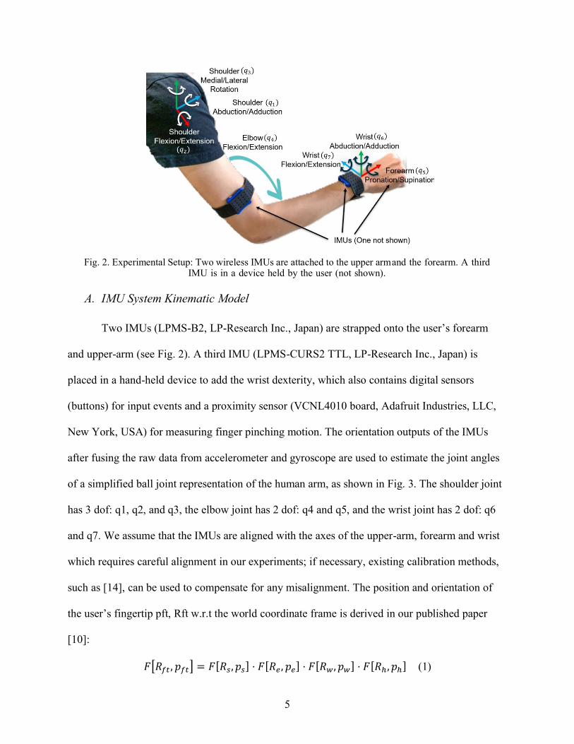
of a simplified ball joint representation of the human arm, as shown in Fig. 3. The shoulder joint
has 3 dof: q1, q2, and q3, the elbow joint has 2 dof: q4 and q5, and the wrist joint has 2 dof: q6
and q7. We assume that the IMUs are aligned with the axes of the upper-arm, forearm and wrist
which requires careful alignment in our experiments; if necessary, existing calibration methods,
such as [14], can be used to compensate for any misalignment. The position and orientation of
the user’s fingertip pft, Rft w.r.t the world coordinate frame is derived in our published paper
[10]:
𝐹[𝑅𝑓𝑡 , 𝑝𝑓𝑡] = 𝐹[𝑅𝑠, 𝑝𝑠] ⋅ 𝐹[𝑅𝑒, 𝑝𝑒] ⋅ 𝐹[𝑅𝑤 , 𝑝𝑤] ⋅ 𝐹[𝑅ℎ , 𝑝ℎ] (1)
6
The hand-held device uses the same spring-loaded mechanism as a staple remover, which
gives the user a realistic haptic feeling when using it to actuate the gripper function on the
teleoperated robot. In addition, the buttons serve as the clutch function with safety mechanism
built in: while the user is not touching the device, the system is in the inactive state which
prevents accidental and unwanted movements that could cause detrimental failures. In the
current work, however, we do not evaluate the digital sensors or proximity sensor in the hand-
held device.
Fig. 3. Simplified ball joint representation of human arm
B. User’s Arm Length Calibration
The developed calibration method requires users to touch at least 4 of the 9 different points
shown in Fig. 4, which can be printed or shown on any flat surface, as long as the physical
distances between the points can be accurately measured. Users should not rotate their hip or
torso during the calibration procedure because the current 2 IMU system assumes that the user’s
shoulder joint is fixed in position and orientation. More importantly, the user needs to touch
different points with fully extended index finger, and without rotating the wrist, then record the
orientation of the 2 IMUs R1 and R2 at each calibration point on the object. The reason that we
7
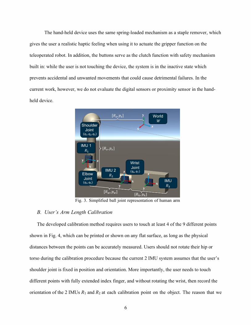
chose to use the user’s extended index finger is because it is a relatively intuitive way for users
to touch designated points on an object.
When the user touches a calibration point 𝑖 on the calibration object, the fingertip
position 𝑝𝑓𝑡(𝑖) is recorded. Then, we compute the distance between where the user’s fingertip
touches points i and j, where 𝑖 ≠ 𝑗, and denote it as the distance from the forward kinematics:
𝑑𝐹𝐾(𝑖, 𝑗) = |𝑝𝑓𝑡(𝑖) − 𝑝𝑓𝑡(𝑗)|, 𝑖 ≠ 𝑗, 𝑖, 𝑗 ∈ [1,2, … , 9] (2)
Similarly, we denote the true physical distance between the same two calibration points as:
𝑑𝑡𝑟(𝑖, 𝑗) = |𝑝𝑡𝑟(𝑖) − 𝑝𝑡𝑟(𝑗)|, 𝑖 ≠ 𝑗, 𝑖, 𝑗 ∈ [1,2, … , 9] (3)
We used the Matlab fmincon optimizer to find the 𝑙𝑢 and 𝑙𝑓 that minimizes:
∑ ‖𝑑𝐹𝐾(𝑖, 𝑗) − 𝑑𝑡𝑟(𝑖, 𝑗)‖𝑖,𝑗 (4)
III. Experiments
The following sections present the experiments performed to compare the teleoperation
performance of our IMU-based system to the Master Tool Manipulator (MTM) from the da
Vinci Research Kit (dVRK), an open-source research platform based on the first-generation da
Vinci surgical robot [15]. In both cases we used visualization in mixed reality on Microsoft
HoloLens.
A. Teleoperation Performance
After calibrating the user’s arm lengths, we evaluate the performance of our system
compared to the MTM from the dVRK, as seen in Fig. 6. To capture the performance of our
proposed system, we designed three tasks with different levels of required dexterity. We
measured both accuracy in position and orientation as well as task completion time.
8
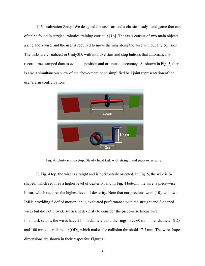
1) Visualization Setup: We designed the tasks around a classic steady-hand game that can
often be found in surgical robotics training curricula [16]. The tasks consist of two main objects,
a ring and a wire, and the user is required to move the ring along the wire without any collision.
The tasks are visualized in Unity3D, with intuitive start and stop buttons that automatically
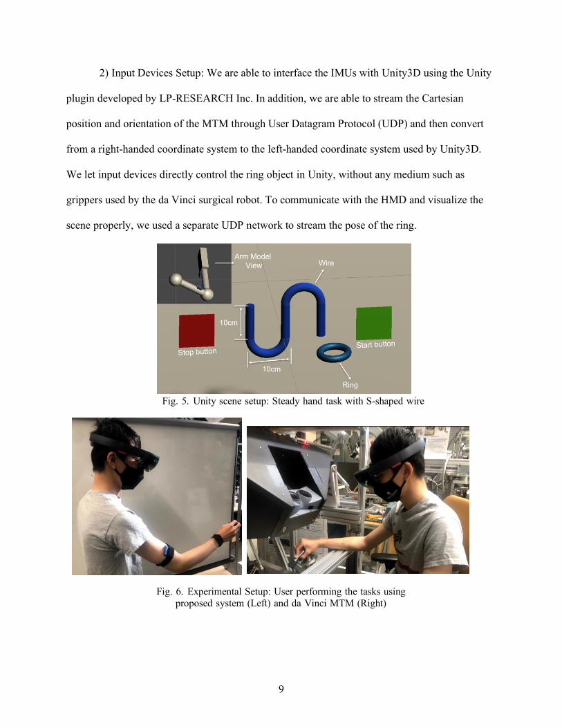
record time stamped data to evaluate position and orientation accuracy. As shown in Fig. 5, there
is also a simultaneous view of the above-mentioned simplified ball joint representation of the
user’s arm configuration.
Fig. 4. Unity scene setup: Steady hand task with straight and piece-wise wire
In Fig. 4 top, the wire is straight and is horizontally oriented. In Fig. 5, the wire is S-
shaped, which requires a higher level of dexterity, and in Fig. 4 bottom, the wire is piece-wise
linear, which requires the highest level of dexterity. Note that our previous work [10], with two
IMUs providing 5 dof of motion input, evaluated performance with the straight and S-shaped
wires but did not provide sufficient dexterity to consider the piece-wise linear wire.
In all task setups, the wires have 25 mm diameter, and the rings have 60 mm inner diameter (ID)
and 100 mm outer diameter (OD), which makes the collision threshold 17.5 mm. The wire shape
dimensions are shown in their respective Figures.
9
2) Input Devices Setup: We are able to interface the IMUs with Unity3D using the Unity
plugin developed by LP-RESEARCH Inc. In addition, we are able to stream the Cartesian
position and orientation of the MTM through User Datagram Protocol (UDP) and then convert
from a right-handed coordinate system to the left-handed coordinate system used by Unity3D.
We let input devices directly control the ring object in Unity, without any medium such as
grippers used by the da Vinci surgical robot. To communicate with the HMD and visualize the
scene properly, we used a separate UDP network to stream the pose of the ring.
Fig. 5. Unity scene setup: Steady hand task with S-shaped wire
Fig. 6. Experimental Setup: User performing the tasks using
proposed system (Left) and da Vinci MTM (Right)
10
IV. Results
A. Teleoperation results
Two users performed each task three times. (Due to the circumstances caused by the
pandemic, we were not allowed to recruit more participants). User1 was familiar with the IMU
system, but had little prior experience with the MTM, while User2 was a novice with the IMU
but had some experience with the MTM. We evaluated the position and orientation accuracy
[17] of both our system and the dVRK while performing the three tasks described above. The
position accuracy, at each point on the motion trajectory, is defined as the distance between 𝑐𝑟𝑖𝑛𝑔
and 𝑐𝑤𝑖𝑟𝑒:
𝑑𝑖𝑠𝑡𝑎𝑛𝑐𝑒(𝑐𝑤𝑖𝑟𝑒, 𝑐𝑟𝑖𝑛𝑔) (5)
where cring is the ring center, and cwire is the point on the wire center-line that is closest to cring.
The orientation accuracy is defined as the angle between the ring orientation vring and the wire
tangent line vwire:
𝑎 = cos−1 𝑣𝑤𝑖𝑟𝑒⋅𝑣𝑟𝑖𝑛𝑔
||𝑣𝑤𝑖𝑟𝑒||⋅||𝑣𝑟𝑖𝑛𝑔|| (6)
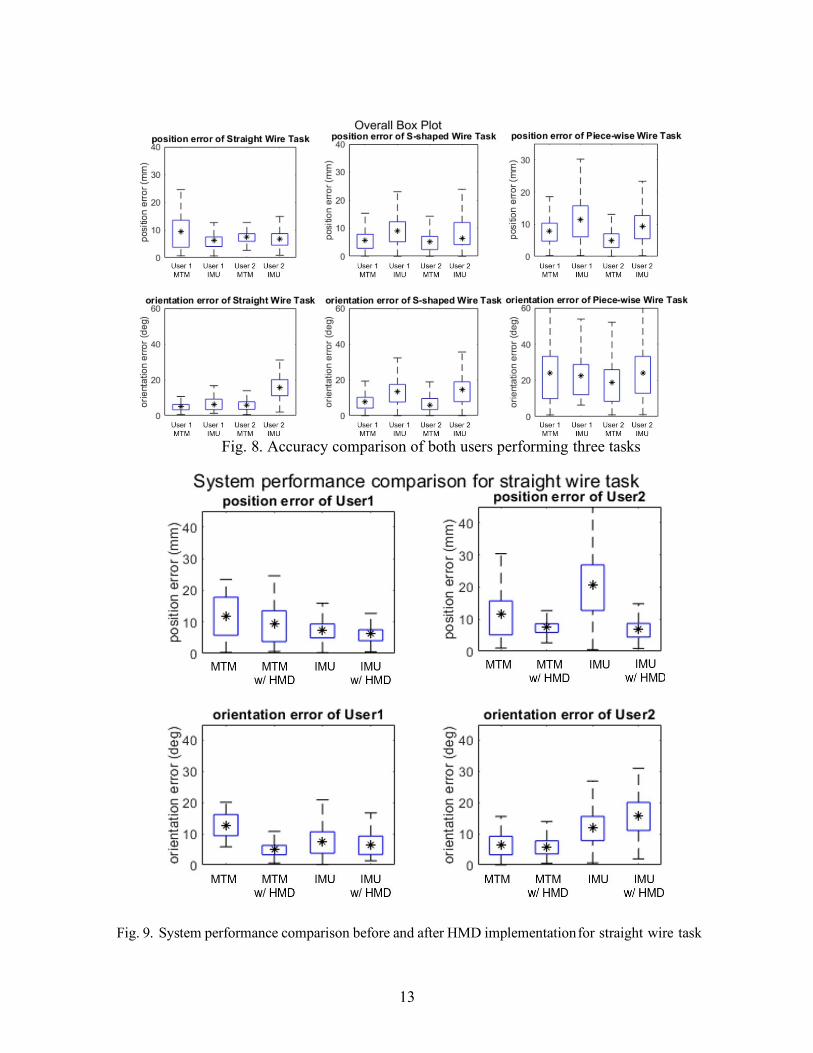
The variation for position and orientation errors with time are presented only for the straight line
task for User1 in Fig. 7. The results for the three tasks performed by both users are summarized
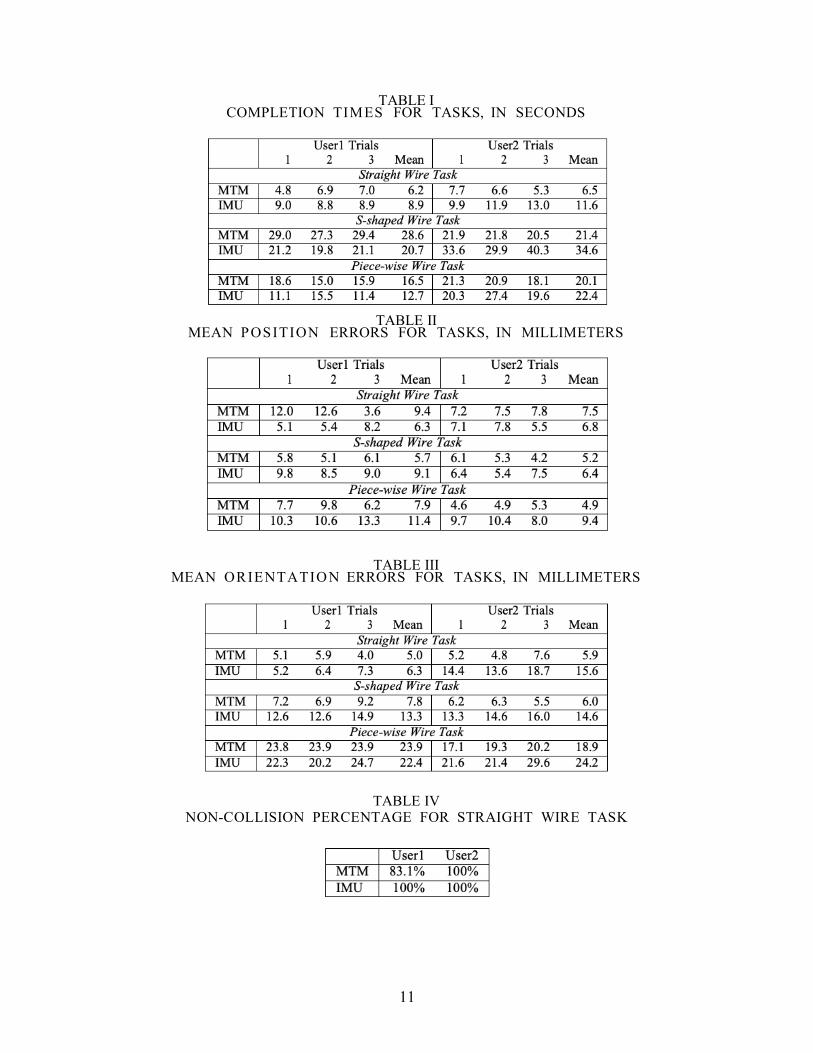
in Fig. 8. Task completion times for the three tasks are provided in Table I. The result shows that
it took longer for User2 to complete the task with an exception of S-shpaed wire tasks using
MTM. Table II and Table III depict the mean position and orientation error for the tasks.
When comparing the performance for the same task and the same user across different input
devices, as represented in Fig. 8 and Tables II, and III, we observe that both users performs
similarly with both systems.
11
TABLE I COMPLETION TIMES FOR TASKS, IN SECONDS
TABLE II
MEAN POSITION ERRORS FOR TASKS, IN MILLIMETERS
TABLE III MEAN ORIENTATION ERRORS FOR TASKS, IN MILLIMETERS
TABLE IV NON-COLLISION PERCENTAGE FOR STRAIGHT WIRE TASK
12
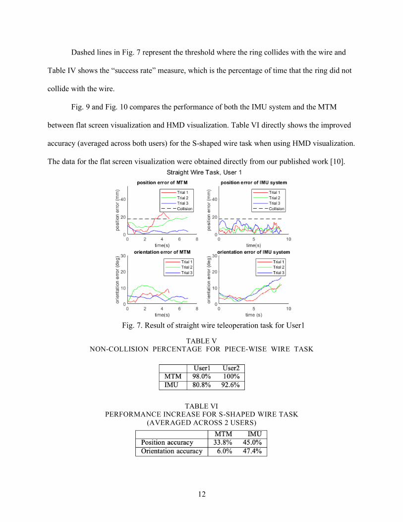
Dashed lines in Fig. 7 represent the threshold where the ring collides with the wire and
Table IV shows the “success rate” measure, which is the percentage of time that the ring did not
collide with the wire.
Fig. 9 and Fig. 10 compares the performance of both the IMU system and the MTM
between flat screen visualization and HMD visualization. Table VI directly shows the improved
accuracy (averaged across both users) for the S-shaped wire task when using HMD visualization.
The data for the flat screen visualization were obtained directly from our published work [10].
Fig. 7. Result of straight wire teleoperation task for User1
TABLE V NON-COLLISION PERCENTAGE FOR PIECE-WISE WIRE TASK
TABLE VI PERFORMANCE INCREASE FOR S-SHAPED WIRE TASK
(AVERAGED ACROSS 2 USERS)
13
Fig. 8. Accuracy comparison of both users performing three tasks
Fig. 9. System performance comparison before and after HMD implementation for straight wire task
14
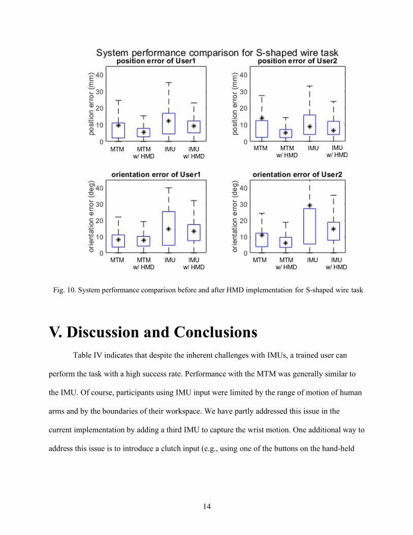
Fig. 10. System performance comparison before and after HMD implementation for S-shaped wire task
V. Discussion and Conclusions
Table IV indicates that despite the inherent challenges with IMUs, a trained user can
perform the task with a high success rate. Performance with the MTM was generally similar to
the IMU. Of course, participants using IMU input were limited by the range of motion of human
arms and by the boundaries of their workspace. We have partly addressed this issue in the
current implementation by adding a third IMU to capture the wrist motion. One additional way to
address this issue is to introduce a clutch input (e.g., using one of the buttons on the hand-held
15
device) so that when users reach the workspace limit, they can clutch and reorient themselves in
a neutral location to have room to continue the task.
Fig. 9, Fig. 10 and Table VI shows that the implementation of the HMD improves the
accuracy of both straight wire and S-shaped tasks, with an exception of the orientation error
when User 2 was doing the straight wire task using the IMU. This further suggests that mixed
reality visualization in the proposed system enhances perception and provides a benefit for
teleoperation. It is also important to note that with the current visualization the gap in
performance between our mobile system and the existing master console is reduced.
While the proposed IMU-based system provided compa- rable performance to the MTM
in terms of allowing the user to specify the motion of the remote object, unlike the mechanically-
grounded MTM, it cannot provide haptic feedback. One possible solution is to include
vibrotactile actuators, for example, mounted on the IMUs. Other possible solutions include
sensory substitution (e.g., graphical overlays [18] or audio cues [19], [20] to indicate measured
force) or force feedback to some other part of the body, such as the forearm or wrist [21].
In summary, this thesis study evaluated the feasibility of mobile teleoperation, using a
head-mounted mixed-reality system and wireless IMUs mounted on the user’s arm, by
comparing the efficiency of the system against a standard mechanical input device used for
robotic surgery. The results show that our proposed solution is a trade-off that adds considerable
mobility while introducing some inaccuracy, though the inaccuracy may be mitigated by user
training. This study provides evidence that although an IMU-based input device is subject to
drift, it can effectively be used in teleoperation scenarios where the operator is closing the
control loop based on visual feedback. A clutch function to address the workspace limitation is
implemented, however needs further refinement for future studies.

16
Bibliography
[1] G. Guthart and J. K. Salisbury Jr, “The Intuitive™ telesurgery system: Overview and application.” in IEEE Intl. Conf. on Robotics and Automation (ICRA), 2000, pp. 618–621.
[2] E. Azimi, A. Winkler, E. Tucker, L. Qian, J. Doswell, N. Navab, and P. Kazanzides, “Can mixed-reality improve the training of medical procedures?” in IEEE Engin. in Medicine and Biology Conf. (EMBC), 7 2018, pp. 112–116.
[3] E. Azimi, J. Doswell, and P. Kazanzides, “Augmented reality goggles with an integrated tracking system for navigation in neurosurgery,” in Virtual Reality Short Papers and Posters (VRW). IEEE, 2012, pp. 123–124.
[4] E. Azimi, Z. Niu, M. Stiber, N. Greene, R. Liu, C. Molina, J. Huang, C.-M. Huang, and P. Kazanzides, “An interactive mixed reality platform for bedside surgical procedures,” in Medical Image Computing and Computer-Assisted Intervention (MICCAI), Oct. 2020, pp. 65–75.
[5] T. Song, C. Yang, O. Dianat, and E. Azimi, “Endodontic guided treatment using augmented reality on a head-mounted display system,” Healthcare Technology Letters, vol. 5, no. 5, pp. 201–207, 2018.
[6] R. T. Azuma, “A survey of augmented reality,” Presence: Teleoperators and virtual environments, vol. 6, no. 4, pp. 355–385, 1997.
[7] R. Xiao, J. Schwarz, N. Throm, A. D. Wilson, and H. Benko, “MRTouch: Adding touch input to head-mounted mixed reality,” IEEE Transactions on Visualization and Computer Graphics, vol. 24, no. 4, pp. 1653–1660, April 2018.
[8] F. Steidle, A. Tobergte, and A. Albu-Scha ffer, “Optical-inertial tracking of an input device for real-time robot control,” in IEEE Intl. Conf. on Robotics and Automation (ICRA), Stockholm, Sweden, May 2016, pp. 742–749.
[9] A. Noccaro, F. Cordella, L. Zollo, G. Di Pino, E. Guglielmelli, and D. Formica, “A teleoperated control approach for anthropomorphic manipulator using magneto-inertial sensors,” RO-MAN 2017 - 26th IEEE International Symposium on Robot and Human Interactive Communica- tion, vol. 2017-January, pp. 156–161, 2017.
[10] G. Fu, E. Azimi, and P. Kazanzides, “Mobile Teleoperation : Feasibility of Wireless Wearable Sensing of the Operator’s Arm Motion,” IROS 2021.
[11] H. Ren, D. Rank, M. Merdes, J. Stallkamp, and P. Kazanzides, “Multisensor data fusion in an integrated tracking system for endoscopic surgery,” IEEE Trans. on Info. Tech. in Biomed., vol. 16, no. 1, pp. 106–111, Jan 2012.
[12] H. Ren and P. Kazanzides, “Investigation of attitude tracking using an integrated inertial and magnetic navigation system for hand-held surgical instruments,” IEEE/ASME Trans. on Mechatronics, vol. 17, no. 2, pp. 210–217, Apr 2012.
[13] C. He, P. Kazanzides, H. T. Sen, S. Kim, and Y. Liu, “An inertial and optical sensor fusion approach for six degree-of-freedom pose estimation,” Sensors, vol. 15, no. 7, pp. 16 448–16 465, Jul 2015.
[14] P. Mueller, M.-A. Begin, T. Schauer, and T. Seel, “Alignment-free, self- calibrating elbow angles measurement using inertial sensors,” IEEE Journal of Biomedical and Health Informatics, vol. 21, no. 2, pp. 312– 319, March 2017.
[15] P. Kazanzides, Z. Chen, A. Deguet, G. S. Fischer, R. H. Taylor, and S. P. DiMaio, “An open-source research kit for the da Vinci® surgical system,” in IEEE Intl. Conf. on Robotics and Auto. (ICRA), Hong Kong, China, Jun 2014, pp. 6434–6439.
[16] A. Mariani, E. Pellegrini, N. Enayati, P. Kazanzides, M. Vidotto, and
[17] E. De Momi, “Design and Evaluation of a Performance-based Adaptive Curriculum for Robotic Surgical Training: A Pilot Study,” Proceedings of the Annual International Conference of the IEEE Engineering in Medicine and Biology Society, EMBS, vol. 2018-July, pp. 2162–2165, 2018.
[18] N. Enayati, A. M. Okamura, A. Mariani, E. Pellegrini, M. M. Coad,
[19] G. Ferrigno, and E. De Momi, “Robotic Assistance-as-Needed for Enhanced Visuomotor Learning in Surgical Robotics Training: An Experimental Study,” Proceedings - IEEE International Conference on Robotics and Automation, pp. 6631–6636, 2018.
17
[20] T. Akinbiyi, C. E. Reiley, S. Saha, D. Burschka, C. J. Hasser, D. D. Yuh, and A. M. Okamura, “Dynamic augmented reality for sensory substitution in robot-assisted surgical systems,” in IEEE Engin. in Medicine and Biology Conf. (EMBC), 2006, pp. 567–570.
[21] M. Balicki, A. Uneri, I. Iordachita, J. Handa, P. Gehlbach, and
[22] R. Taylor, “Micro-force sensing in robot assisted membrane peeling for vitreoretinal surgery,” in Medical Image Computing and Computer- Assisted Intervention (MICCAI), 2010, pp. 303–310.
[23] N. Cutler, M. Balicki, M. Finkelstein, J. Wang, P. Gehlbach, J. McGready,
[24] Iordachita, R. Taylor, and J. T. Handa, “Auditory force feedback substitution improves surgical precision during simulated ophthalmic surgery,” Investigative Ophthalmology & Visual Science, vol. 54, no. 2, pp. 1316–1324, Feb. 2013.
[25] G. Ng, P. Barralon, G. Dumont, S. K. W. Schwarz, and J. M. Ansermino, “Optimizing the tactile display of physiological information: Vibro-tactile vs. electro-tactile stimulation, and forearm or wrist location,” in IEEE Engin. in Medicine and Biology Conf. (EMBC), Aug. 2007, pp. 4202– 4205.