evaluation of adhesion/cohesion bond strength of the thick plasma
TRANSCRIPT

Tribology International 44 (2011) 1281–1288
Contents lists available at ScienceDirect
Tribology International
0301-67
doi:10.1
$The
(WTC IVn Corr
E-m
saioa.ar
gregory
miki@in
vpopov
journal homepage: www.elsevier.com/locate/triboint
Evaluation of adhesion/cohesion bond strength of the thick plasma spraycoatings by scratch testing on coatings cross-sections$
Aleksandar Vencl a,n, Saioa Arostegui b, Gregory Favaro b, Fatima Zivic c, Mihailo Mrdak d,Slobodan Mitrovic c, Vladimir Popovic a
a Mechanical Engineering Faculty, University of Belgrade, Kraljice Marije 16, 11120 Belgrade 35, Serbiab CSM Instruments SA, Rue de la Gare 4, CH-2034 Peseux, Switzerlandc Mechanical Engineering Faculty, University of Kragujevac, Sestre Janjic 6, 34000 Kragujevac, Serbiad IMTEL Microwaves Inc., Bulevar Mihaila Pupina 165b, 11070 Belgrade, Serbia
a r t i c l e i n f o
Article history:
Received 2 February 2011
Received in revised form
1 April 2011
Accepted 4 April 2011Available online 12 April 2011
Keywords:
Plasma spray coating
Bond strength
Scratch test
Tensile test
9X/$ - see front matter & 2011 Elsevier Ltd. A
016/j.triboint.2011.04.002
paper was originally presented at the Wor
) Kyoto, Japan, 6th–11th September 2009.
esponding author. Tel.: þ381 11 33 02 291; f
ail addresses: [email protected] (A. Vencl),
[email protected] (S. Arostegui),
[email protected] (G. Favaro), ziv
simtel.com (M. Mrdak), [email protected] (S. M
[email protected] (V. Popovic).
a b s t r a c t
The possibility of adhesion/cohesion bond strength evaluation of thick plasma spray coatings with
scratch tester, according to the ISO working draft (ISO/WD 27307), was analyzed and compared with
the standard test method (ASTM C 633). Four different coatings deposited with atmospheric plasma
spraying were used. The results showed that scratch testing could be used as an efficient method for
evaluation of thick plasma spray coatings cohesion. It is a relatively easy and quick test method, and for
practical application it could be also used as a supplement of some standard test method as a coating
characterization and quality control technique.
& 2011 Elsevier Ltd. All rights reserved.
1. Introduction
Plasma spraying is a well established and versatile technique,and has been widely applied in modifying surface properties ofmetal components. Plasma spray coatings could have variousfunctions such as improving wear resistance and thermal orchemical resistance. It may also improve special electrical, mag-netic or decorative properties of the substrate. This type ofcoatings finds applications in many industries [1,2], e.g. thickcoatings are applied in many industrial areas to restore or attaindesired work piece dimensions and specifications.
Plasma spray coating characteristics are very dependent onspray parameters. According to some researchers [3] there aremore than 50 macroscopic parameters that influence the qualityof the coating. Depending on the application of plasma spraycoating, different characteristics are important but there are somecharacteristics that are the same for all applications: thickness,porosity, microstructure, presence of unmelted particles, cracks
ll rights reserved.
ld Tribology Congress 2009
ax: þ381 11 33 70 364.
[email protected] (F. Zivic),
itrovic),
and oxides, microhardness and bond strength. The poor bondingbetween splats and the imperfections in the form of pores orthermal cracks cause the mechanical property values of plasmaspray coatings to be considerably lower than those of thecorresponding monolithic materials [4]. Evidently the quality ofa thermal spray coating is, to a large extent, determined by thequality of its adhesion between the coating and the underlyingsubstrate as well as its cohesion among splats, i.e. adhesion/cohesion bond strength [1,5,6]. Adhesion bond strength primarilydetermines the quality of a coating while the cohesion bondstrength indicates coating wear behavior.
There are a large range of available laboratory test methods forthe evaluation of the thin or thick coatings adhesion/cohesionbond strength [1,5,7,8]. However none of them may be regardedas ideal, and all of them have certain advantages and disadvan-tages. Moreover, the results obtained are hard to be compared.Compared to other methods, the scratch test is fairly reliable,simple to use and no special specimen shape or preparation isrequired [9]. In addition, scratch testing is very useful foroptimization of plasma spraying parameters [10]. The scratchtest has been used for many years to provide a measure ofcoating/substrate adhesion [11], and determination of adhesiveand other mechanical failure modes of thin coatings (up to20 mm) by scratching the coatings surface has already beenstandardized [12].
Recently there have been attempts to determine the adhesionof thermal spray coatings by using scratch tests for thick coatings

A. Vencl et al. / Tribology International 44 (2011) 1281–12881282
in the same manner as in the thin coatings, i.e. scratching on thetop surface of the coating with constant or increasing load.However, due to a much higher thickness and surface roughnessof thermal spray coatings the method has been found to beunsatisfactory [13]. In order to solve this problem a new methodfirst introduced by Lopez et al. [14] that consists of running aconstant load scratch test on a cross-section of the coating wasproposed by ISO [15].
This paper analyzes the possibility of adhesion/cohesion bondstrength evaluation of the thick plasma spray coatings by scratchtesting on coatings cross-sections, according to the ISO workingdraft (ISO/WD 27307), and compares it to the most commonlyapplied standard tensile test method for adhesion or cohesionstrength of thermal spray coatings (ASTM C 633). Both testsbelong to the mechanical methods group [5] in which theadhesion is determined by the application of a force to thecoating/substrate system. Materials used in the tests were fourdifferent plasma spray coatings whose bond strengths weremeasured by both test methods, compared and discussed.
Table 2Selected APS spray parameters values used for coatings deposition.
Spray parameter Coating
4052 92F 505 34F
Primary plasma gas, Ar (l/min) 100 80 47 47
Secondary plasma gas, H2 (l/min) 5 15 10 12
Electric current (A) 500 500 500 500
Powder carrier gas, Ar (l/min) 37 37 5 4
Powder feed rate (kg/h) 2 4.5 2.4 1.8
Spray distance (mm) 150 75 130 125
2. Experimental details
2.1. Materials
Four spray powders were used in the experiment: two ferrousbased powders (Sulzer Metco 4052 and Metco 92F), one molyb-denum based powder (Metco 505) and one tungsten carbide–cobalt based powder (Metco 34F). The chemical compositions ofthe powders are shown in Table 1.
The Sulzer Metco 4052 powder is made of slightly alloyed steel,processed by gas atomization. It shows fine spherical morphologywith particle granulation �38/þ15 mm. Metco 92F is a fine grade ofhigh carbon iron powder, processed by water atomization, whichshows irregular morphology with particle granulation –53/þ10 mm.The Metco 505 powder is a blend of molybdenum and nickel–chrome self-fluxing alloy. The share of the individual powder in theblend was 75 wt% of molybdenum and 25 wt% of nickel–chromeself-fluxing alloy. This spray powder blend shows spherical mor-phology with particle granulation –90/þ15 mm. The Metco 34Fpowder is composed of a fine tungsten carbide–cobalt powderblended with a fine nickel–chrome self-fluxing alloy powder. Itcontains 50 wt% of tungsten carbide–cobalt and 50 wt% of nickel–chrome self-fluxing alloy. Particle granulation of this spray powderblend was �53/þ15 mm.
The substrate material for the first two ferrous based coatingswas a Al–Si alloy (EN AlSi10Mg), which was produced using sandcasting followed by solution annealing at 540 1C with 35 1C/h,water quenching and artificial ageing at 16075 1C for 6 h. Thesubstrate material for the other two coatings (molybdenum basedand tungsten carbide–cobalt based) was a stainless steel (ENX15Cr13). This substrate material was used without any heattreatment. For the convenience, coatings attained using SulzerMetco 4052, Metco 92F, Metco 505 and Metco 34F powders arehereafter referred to as 4052, 92F, 505 and 34F, respectively.
Table 1Chemical composition of used powders in wt%.
Powdera C Mn Mo WC12Co
Sulzer Metco 4052 1.2 1.5 – –
Metco 92F 3.5 0.35 – –
Metco 505 0.2 – 75 –
Metco 34F 0.5 – – 50
a Commercial brand names of Sulzer Metco Inc. and Metco Inc.
A deposition of all coatings was done by atmospheric plasmaspraying (APS) process. Coatings 4052 and 92F were depositedwith a Metco 7MB plasma spray gun, while coatings 505 and 34Fwere deposited with a Plasmadyne SG-100 plasma spray gun. Inboth cases specimen holder was rotated at constant speed of500 mm/s while the traverse speed of a spraying gun wasmaintained constant at 4 mm/s. Before the spraying process, thesurface of the substrate was activated and preheated. Activation(roughening) was done with an appropriate abrasive. The targetcoating thickness for all specimens was 350–400 mm. The selectedspray parameters are given in Table 2.
2.2. Microstructure analysis and indentation tests
Metallographic samples were prepared in a standard wayapplying grinding and polishing with no etching, where thecoatings were sectioned perpendicular to the coated surface.The microstructure of the coatings and presence of the crackswere analyzed with an optical microscope (OM) and a scanningelectron microscope (SEM). Characterization was done accordingto the Pratt & Whitney standard [16].
Indentation tests of the obtained coatings included hardness,modulus of elasticity and plasticity measurements and measure-ments were made on the cross-sectional surface of the coatings(perpendicular to the coated surface). These tests were carried outusing a CSM micro-indentation tester and applying the Instru-mented indentation technique [17,18]. The Instrumented inden-tation technique is described in detail in the appropriate ISO14577 standard.
The micro-indentation tester uses an already establishedmethod where an indenter tip with a known geometry is driveninto the specific site of the material to be tested, by applying anincreasing normal load. When reaching the pre-set maximumvalue, the normal load is reduced until partial or completerelaxation occurs. At each stage of the experiment the positionof the indenter relative to the sample surface is preciselymonitored with a differential capacitive sensor. With the constantmulticycle mode, which is used in tests, indents are repeated inthe same place several times (cycles) in order to provide informa-tion about the fatigue behavior of the coating. This procedure wasperformed in ambient air, at the temperature of 23 1C and
Ni Cr B Si Fe
0.3 1.3 – – Balance
– – – – Balance
Balance 4.25 0.8 1.0 1.0
33 9 2.0 2.0 3.5

Fig. 2. OM images of the cone fracture area and nomenclature.
A. Vencl et al. / Tribology International 44 (2011) 1281–1288 1283
humidity of 40%. The following indentation parameters were usedto produce two multicycle indents on each sample: indenterVickers; contact load 10 mN; constant loading rate 5 N/s; max-imum load 15 N; reduced load (unload value) 5 N and number ofcycles 100 cycles (see Fig. 5).
The indentation hardness, HIT, is defined as the mean contactpressure and is given by
HIT ¼Fmax
ApðMPaÞ,
where Fmax is the maximum normal load (Fig. 1) and Ap is theprojected contact area at that load. For better comparison of theresults indentation hardness was converted to the Vickers hard-ness, HV. For a Vickers indenter the angle between the axis ofdiamond pyramid and its faces is a¼681, so we have the followingrelation:
HV ¼ 0:0945HIT :
The indentation modulus, EIT, is calculated from the slope ofthe tangent of the unloading curve (Fig. 1)
EIT ¼1�n2
s
ð1=ErÞ�ð1�n2i =EiÞ
ðGPaÞ,
where Ei is the elastic modulus of the indenter (1141 GPa fordiamond), ni is Poisson’s ratio of the indenter (0.07 for diamond)and ns is Poisson’s ratio of the tested sample. Determination ofelasticity modulus was done under the assumption that all testedmaterials have Poisson’s ratio of 0.3. The reduced modulus, Er,which is calculated from the indentation data, is defined as
Er ¼
ffiffiffiffiffiffiffiffiffiffiffiffiffiffiffiffipS
2bffiffiffiffiffiffiAp
ps
ðGPaÞ,
where S is the contact stiffness (S¼dF/d Pd, Fig. 1) and b is ageometric factor depending on the diamond shape, which in ourcase was square (b¼1.012). In order to compare the elasticproperties of all samples, the parameter plasticity was definedand calculated from the following equation:
plasticity¼Pdmax�Pd1
Pdmax,%,
where Pd1 is penetration depth of first indent and Pdmax ismaximal penetration depth (Fig. 1).
Fig. 1. Typical load vs. penetration depth curve for the Instrumented indentation
technique constant multicycle mode.
2.3. Adhesion/cohesion bond strength—tensile bond strength test
(ASTM)
Tensile bond strength tests on the coatings were performedaccording to the ASTM C 633 standard. These tests were carried outusing an Instron M 1185 hydraulic tensile test machine, applyingcross-head velocities of 0.5 mm/min (coatings 4052 and 92F) and1 mm/min (coatings 505 and 34F). The geometry of the specimenswas cylindrical, Ø25�50 mm2. Two specimens in pair were used,and the coating was deposited only on one of them. Specimenswere bonded by glue and kept pressed against each other in afurnace. The bond strength was calculated by dividing the max-imum (failure) load by the cross-sectional area of the specimen.The presented results of the coatings tensile bond strength testsrepresent an average value of a larger number of tests.
2.4. Adhesion/cohesion bond strength—scratch bond strength test (ISO)
Scratch bond strength tests on the coatings were performedaccording to the ISO/WD 27307 working draft. These tests werecarried out using a CSM micro-scratch tester in ambient air, at thetemperature of 23 1C and humidity of 40%. The following testparameters were used to produce three identical scratches on eachspecimen: indenter (stylus) type Rockwell diamond; stylus radius50 mm; constant normal load 4 N; scratch length 0.7 mm andstylus velocity 1.4 mm/min. Specimens were embedded in resinand then polished in a standard way as metallographic samples.The scratch tests were carried out on cross-sections of the coatingsand the stylus was slided from substrate towards the coatings.
During scratch bond strength tests, several data were measuredand recorded such as normal, friction and critical force, coefficientof friction, and penetration and residual depth of the stylus. Afterthe tests, the geometric values of the resulting cone-shapedfracture were also measured: cone length (Lx), width (2yLy),and angle (a), and projected cone area (Acn¼LxLy; Fig. 2). Basedon some other research [17] the projected cone area (Acn) waschosen as the most characteristic factor for comparison, since itshowed only a monotonic relationship to the scratching load.
3. Results
3.1. Microstructure and indentation tests results
The microstructures of the investigated coatings are shown inFigs. 3 and 4. The microstructures of all coatings were typical for
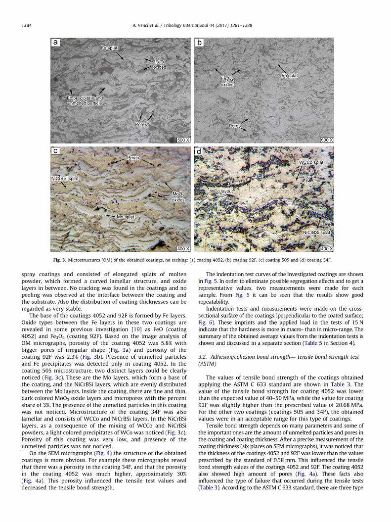
Fig. 3. Microstructures (OM) of the obtained coatings, no etching: (a) coating 4052, (b) coating 92F, (c) coating 505 and (d) coating 34F.
A. Vencl et al. / Tribology International 44 (2011) 1281–12881284
spray coatings and consisted of elongated splats of moltenpowder, which formed a curved lamellar structure, and oxidelayers in between. No cracking was found in the coatings and nopeeling was observed at the interface between the coating andthe substrate. Also the distribution of coating thicknesses can beregarded as very stable.
The base of the coatings 4052 and 92F is formed by Fe layers.Oxide types between the Fe layers in these two coatings arerevealed in some previous investigation [19] as FeO (coating4052) and Fe3O4 (coating 92F). Based on the image analysis ofOM micrographs, porosity of the coating 4052 was 5.8% withbigger pores of irregular shape (Fig. 3a) and porosity of thecoating 92F was 2.3% (Fig. 3b). Presence of unmelted particlesand Fe precipitates was detected only in coating 4052. In thecoating 505 microstructure, two distinct layers could be clearlynoticed (Fig. 3c). These are the Mo layers, which form a base ofthe coating, and the NiCrBSi layers, which are evenly distributedbetween the Mo layers. Inside the coating, there are fine and thin,dark colored MoO3 oxide layers and micropores with the percentshare of 3%. The presence of the unmelted particles in this coatingwas not noticed. Microstructure of the coating 34F was alsolamellar and consists of WCCo and NiCrBSi layers. In the NiCrBSilayers, as a consequence of the mixing of WCCo and NiCrBSipowders, a light colored precipitates of WCo was noticed (Fig. 3c).Porosity of this coating was very low, and presence of theunmelted particles was not noticed.
On the SEM micrographs (Fig. 4) the structure of the obtainedcoatings is more obvious. For example these micrographs revealthat there was a porosity in the coating 34F, and that the porosityin the coating 4052 was much higher, approximately 30%(Fig. 4a). This porosity influenced the tensile test values anddecreased the tensile bond strength.
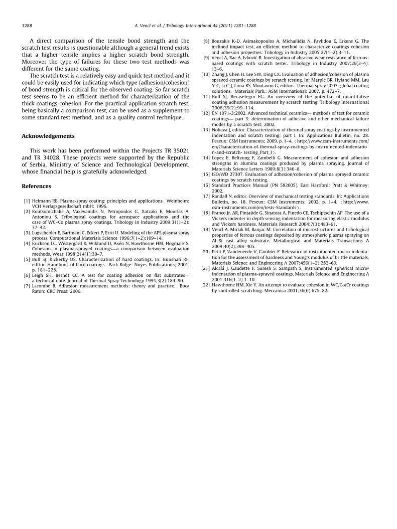
The indentation test curves of the investigated coatings are shownin Fig. 5. In order to eliminate possible segregation effects and to get arepresentative values, two measurements were made for eachsample. From Fig. 5 it can be seen that the results show goodrepeatability.
Indentation tests and measurements were made on the cross-sectional surface of the coatings (perpendicular to the coated surface;Fig. 6). These imprints and the applied load in the tests of 15 Nindicate that the hardness is more in macro- than in micro-range. Thesummary of the obtained average values from the indentation tests isshown and discussed in a separate section (Table 5 in Section 4).
3.2. Adhesion/cohesion bond strength— tensile bond strength test
(ASTM)
The values of tensile bond strength of the coatings obtainedapplying the ASTM C 633 standard are shown in Table 3. Thevalue of the tensile bond strength for coating 4052 was lowerthan the expected value of 40–50 MPa, while the value for coating92F was slightly higher than the prescribed value of 20.68 MPa.For the other two coatings (coatings 505 and 34F), the obtainedvalues were in an acceptable range for this type of coatings.
Tensile bond strength depends on many parameters and some ofthe important ones are the amount of unmelted particles and pores inthe coating and coating thickness. After a precise measurement of thecoating thickness (six places on SEM micrographs), it was noticed thatthe thickness of the coatings 4052 and 92F was lower than the valuesprescribed by the standard of 0.38 mm. This influenced the tensilebond strength values of the coatings 4052 and 92F. The coating 4052also showed high amount of pores (Fig. 4a). These facts alsoinfluenced the type of failure that occurred during the tensile tests(Table 3). According to the ASTM C 633 standard, there are three type
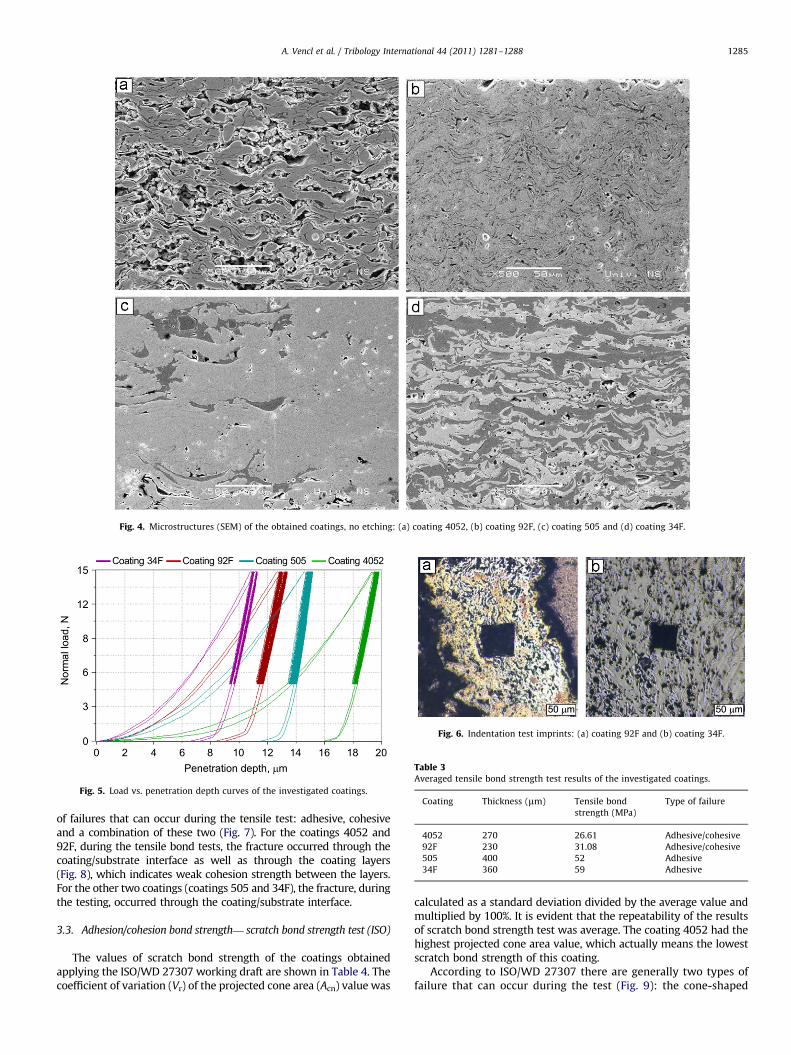
Fig. 5. Load vs. penetration depth curves of the investigated coatings.
Fig. 6. Indentation test imprints: (a) coating 92F and (b) coating 34F.
Fig. 4. Microstructures (SEM) of the obtained coatings, no etching: (a) coating 4052, (b) coating 92F, (c) coating 505 and (d) coating 34F.
Table 3Averaged tensile bond strength test results of the investigated coatings.
Coating Thickness (mm) Tensile bond
strength (MPa)
Type of failure
4052 270 26.61 Adhesive/cohesive
92F 230 31.08 Adhesive/cohesive
505 400 52 Adhesive
34F 360 59 Adhesive
A. Vencl et al. / Tribology International 44 (2011) 1281–1288 1285
of failures that can occur during the tensile test: adhesive, cohesiveand a combination of these two (Fig. 7). For the coatings 4052 and92F, during the tensile bond tests, the fracture occurred through thecoating/substrate interface as well as through the coating layers(Fig. 8), which indicates weak cohesion strength between the layers.For the other two coatings (coatings 505 and 34F), the fracture, duringthe testing, occurred through the coating/substrate interface.
3.3. Adhesion/cohesion bond strength— scratch bond strength test (ISO)
The values of scratch bond strength of the coatings obtainedapplying the ISO/WD 27307 working draft are shown in Table 4. Thecoefficient of variation (Vr) of the projected cone area (Acn) value was
calculated as a standard deviation divided by the average value andmultiplied by 100%. It is evident that the repeatability of the resultsof scratch bond strength test was average. The coating 4052 had thehighest projected cone area value, which actually means the lowestscratch bond strength of this coating.
According to ISO/WD 27307 there are generally two types offailure that can occur during the test (Fig. 9): the cone-shaped

Table 4Averaged scratch bond strength test results of the investigated coatings.
Coating Cone
length Lx
(mm)
Cone
width 2Ly
(mm)
Projected cone
area Acn�10�3
(mm2)
Coefficient of
variation Vr
(%)
Type of
failure
4052 71.00 177.46 6.32 19.73 Cohesive
92F 51.03 117.48 3.00 16.63 Cohesive
505 30.45 89.83 1.37 18.27 Cohesive
34F 17.17 72.52 0.63 26.57 Cohesive
Fig. 9. Classification of the failure location for the scratch bond strength test.
Fig. 10. Cone-shaped fracture occurring during the scratch bond str
Fig. 7. Nomenclature of specimen components and classification of failure
location for the tensile bond strength test.
Fig. 8. Example of two types of failure for the tensile bond strength test (coating
4052): (a) adhesive and (b) cohesive.
A. Vencl et al. / Tribology International 44 (2011) 1281–12881286
fracture at the substrate/coating interface (indication of thecoating adhesion) and the cone-shaped fracture in the coating(indication of the coating cohesion). As expected the cone-shapedfracture occurred on all the examined coatings (Fig. 10). Using theOM images after the scratch test it is very easy to indicate whichtype (adhesion/cohesion) of bond strength is critical for theobserved coating. For all coatings the cone-shaped fracture occursjust inside the coatings, which reveals that the failure is due to aproblem of cohesion within the coating itself (Table 4). Only oncoating 505 small cracks were observed around the scratch,which decreased the values of the cohesive strength. These cracksare more obvious on the SEM image of the coating 505 scratchpath (Fig. 11).
4. Correlation of the results and discussion
Four different thick plasma spray coatings were investigated inorder to investigate the possibility of the adhesion/cohesion bondstrength evaluation with scratch tester, by comparing it to thestandard tensile test method. Since the higher projected cone areavalue actually means lower scratch bond strength of the coating,the parameter of inverted projected cone was used for thecorrelation of the two bond strength test results. The results ofboth tests, as well as the results of mechanical characteristics, aresummarized in Table 5. For validation of the results, repeatabilityof the scratch bond strength test results must be considered sinceit was not the best one.
There have been some questions regarding the estimation ofthe brittle materials hardness using the Instrumented micro-indentation technique [20] but authors proved that if certainconditions (surface polishing, rigidity of samples and avoidanceof cracks) are taken into consideration, it is possible to use this
ength test: (a) coating 92F, (b) coating 505 and (c) coating 34F.
Fig. 11. Observed cracks around the scratch on the coating 505 (SEM).

Table 5Mechanical characteristics and bond strength tests results of the investigated coatings.
Coating Mechanical characteristics Tensile test (ASTM) Scratch test (ISO)
Hardness
HV 1.5
Modulus of
elasticity (GPa)
Plasticity (%) Tensile bond
strength (MPa)
Type of failure Projected cone area
invert value (mm�2)
Type of
failure
4052 175 65.5 1.52 26.61 Adhesive/cohesive 158.19 Cohesive
92F 445 99 2.50 31.08 Adhesive/cohesive 333.61 Cohesive
505 299 118 3.31 52 Adhesive 730.65 Cohesive
34F 645 127 1.57 59 Adhesive 1592.90 Cohesive
Fig. 12. Graphical correlation of the two bond strength tests and influencing parameters effects.
A. Vencl et al. / Tribology International 44 (2011) 1281–1288 1287
technique efficiently in characterization of brittle materials.One of the main requests imposed on the test is to applyindentation load lower than the value that produces cracks onimprints. Alcala et al. [21] also emphasized that it is important tochoose the indentation load in such a way as to avoid occurrenceof microcracking at corners of the imprint. Since there were nocracks on the indentation test imprints (Fig. 6), it is obvious thatthe obtained values of hardness and elasticity modulus can beconsidered as appropriate for further analysis.
The first feature is that the hardness of the coating is not incorrelation with either tensile or scratch bond strength values.This suggests that, for this type of materials, the Instrumentedindentation hardness is not the best property for predicting theadhesion/cohesion bond strength. On the other hand, the mod-ulus of elasticity was in correlation with the bond strength valuesof both test methods, i.e. higher modulus of elasticity implieshigher tensile bond strength and higher scratch bond strength(Table 5). According to Hawthorne and Xie [22] the cohesivestrength of plasma spray coatings includes many factors.Although some of these factors are difficult to measure individu-ally, the cohesive strength of a material is closely linked to itsresistance to contact deformation and its ability to deform with-out fracture [22]. This is in correlation with the obtained resultssince, for example, the coating 34F showed the highest values ofelasticity modulus, i.e. resistance to contact deformation, and thehighest values of the bond strength in both test methods as well.The plasticity for all coatings was very low, which is expected forbrittle materials. There was a general trend between the tensile andscratch bond strength that coatings with higher tensile bondstrength had higher scratch bond strength, but a direct comparisonof the tensile and the scratch test results is questionable. A graphicalinterpretation of the relationship between two bond strength testresults is shown in Fig. 12. It could be noticed that the relationship is
more exponential than linear. There are small deviations of themeasured values from the theoretical exponentional curve, first ofall due to the coating deposition process parameters and secondlydue to the observed failures during the tests.
Porosity generally decreases tensile test values since a pore ofcritical size can induce a macroscopic failure with tensile stressapplied, while with compressive stress (scratch test) it is lessinfluential. That is why the values of the cohesive tensile bondstrength for coating 34F, and especially for coating 4052 (highporosity), are lower than expected (Fig. 12). Together with coatingthickness smaller than the standard prescribed values, porositycould also increase the values of tensile bond strength since thereis a possibility for glue to penetrate through the coating. Havingthis in mind and the fact that the thickness of coatings 4052 and92F was smaller than it should be, it is possible that the tensiletest values for these coatings are increased.
Microcracks, similar to the pores, can induce macroscopicfailure when load of appropriate value is applied. Small cracksaround the scratch path, observed after the test on the coating505, decreased scratch test cohesive strength. For better correla-tion of the results more coatings should be tested while tribolo-gical tests (in dry and lubricated conditions) could also help inconfirmation of the scratch test results (cohesion of the coatings).
5. Conclusions
After the characterization of the four different thick plasmaspray coatings and examinations with scratch tester and withtensile test machine, some regularities could be established. Firstof all, it is confirmed that for this type of material, hardness is notthe best property for predicting the adhesive/cohesive bondstrength, which was expected.
A. Vencl et al. / Tribology International 44 (2011) 1281–12881288
A direct comparison of the tensile bond strength and thescratch test results is questionable although a general trend existsthat a higher tensile implies a higher scratch bond strength.Moreover the type of failures for these two test methods wasdifferent for the same coating.
The scratch test is a relatively easy and quick test method and itcould be easily used for indicating which type (adhesion/cohesion)of bond strength is critical for the observed coating. So far scratchtest seems to be an efficient method for characterization of thethick coatings cohesion. For the practical application scratch test,being basically a comparison test, can be used as a supplement tosome standard test method, and as a quality control technique.
Acknowledgements
This work has been performed within the Projects TR 35021and TR 34028. These projects were supported by the Republicof Serbia, Ministry of Science and Technological Development,whose financial help is gratefully acknowledged.
References
[1] Heimann RB. Plasma-spray coating: principles and applications. Weinheim:VCH Verlagsgesellschaft mbH; 1996.
[2] Koutsomichalis A, Vaxevanidis N, Petropoulos G, Xatzaki E, Mourlas A,Antoniou S. Tribological coatings for aerospace applications and thecase of WC–Co plasma spray coatings. Tribology in Industry 2009;31(1–2):37–42.
[3] Lugscheider E, Barimani C, Eckert P, Eritt U. Modeling of the APS plasma sprayprocess. Computational Materials Science 1996;7(1–2):109–14.
[4] Erickson LC, Westergard R, Wiklund U, Axen N, Hawthorne HM, Hogmark S.Cohesion in plasma-sprayed coatings—a comparison between evaluationmethods. Wear 1998;214(1):30–7.
[5] Bull SJ, Rickerby DS. Characterization of hard coatings. In: Bunshah RF,editor. Handbook of hard coatings. Park Ridge: Noyes Publications; 2001.p. 181–228.
[6] Leigh SH, Berndt CC. A test for coating adhesion on flat substrates—
a technical note. Journal of Thermal Spray Technology 1994;3(2):184–90.[7] Lacombe R. Adhesion measurement methods: theory and practice. Boca
Raton: CRC Press; 2006.
[8] Bouzakis K-D, Asimakopoulos A, Michailidis N, Pavlidou E, Erkens G. Theinclined impact test, an efficient method to characterize coatings cohesionand adhesion properties. Tribology in Industry 2005;27(1–2):3–11.
[9] Vencl A, Rac A, Ivkovic B. Investigation of abrasive wear resistance of ferrous-based coatings with scratch tester. Tribology in Industry 2007;29(3–4):
13–6.[10] Zhang J, Chen H, Lee SW, Ding CX. Evaluation of adhesion/cohesion of plasma
sprayed ceramic coatings by scratch testing. In: Marple BR, Hyland MM, LauY-C, Li C-J, Lima RS, Montavon G, editors. Thermal spray 2007: global coatingsolutions. Materials Park,: ASM International; 2007. p. 472–7.
[11] Bull SJ, Berasetegui EG. An overview of the potential of quantitativecoating adhesion measurement by scratch testing. Tribology International
2006;39(2):99–114.[12] EN 1071-3:2002. Advanced technical ceramics— methods of test for ceramic
coatings— part 3: determination of adhesive and other mechanical failuremodes by a scratch test; 2002.
[13] Nohava J, editor. Characterization of thermal spray coatings by instrumentedindentation and scratch testing: part I. In: Applications Bulletin, no. 28.Peseux: CSM Instruments; 2009. p. 1–4. /http://www.csm-instruments.com/
en/Characterization-of-thermal-spray-coatings-by-instrumented-indentation-and-scratch- testing_Part_IS.
[14] Lopez E, Beltzung F, Zambelli G. Measurement of cohesion and adhesionstrengths in alumina coatings produced by plasma spraying. Journal ofMaterials Science Letters 1989;8(3):346–8.
[15] ISO/WD 27307. Evaluation of adhesion/cohesion of plasma sprayed ceramiccoatings by scratch testing.
[16] Standard Practices Manual (PN 582005). East Hartford: Pratt & Whitney;2002.
[17] Randall N, editor. Overview of mechanical testing standards. In: ApplicationsBulletin, no. 18. Peseux: CSM Instruments; 2002. p. 1–4. /http://www.
csm-instruments.com/en/tests-StandardsS.[18] Franco Jr. AR, Pintaude G, Sinatora A, Pinedo CE, Tschiptschin AP. The use of a
Vickers indenter in depth sensing indentation for measuring elastic modulusand Vickers hardness. Materials Research 2004;7(3):483–91.
[19] Vencl A, Mrdak M, Banjac M. Correlation of microstructures and tribological
properties of ferrous coatings deposited by atmospheric plasma spraying onAl–Si cast alloy substrate. Metallurgical and Materials Transactions A
2009;40(2):398–405.[20] Petit F, Vandeneede V, Cambier F. Relevance of instrumented micro-indenta-
tion for the assessment of hardness and Young’s modulus of brittle materials.Materials Science and Engineering A 2007;456(1–2):252–60.
[21] Alcala J, Gaudette F, Suresh S, Sampath S. Instrumented spherical micro-
indentation of plasma-sprayed coatings. Materials Science and Engineering A2001;316(1–2):1–10.
[22] Hawthorne HM, Xie Y. An attempt to evaluate cohesion in WC/Co/Cr coatingsby controlled scratching. Meccanica 2001;36(6):675–82.