module design, materials, & packaging research … · currents, internal resistance ... depend...
TRANSCRIPT
Module Design, Materials, & Packaging Research• T. J. McMahon (1.0)• Steve Glick (1.0)• Gary Jorgensen (0.85)• Mike Kempe (1.0)• John Pern (0.5)• Kent Terwilliger (0.5)
FY 06 Total 4.85 FTEs
FY 07 Total 4.00 FTEs
Purpose of this Task
• Confirm reliability of new photovoltaic packaging materials and strategies to insure a 30-year module life. Usually Industrial collaborations.
• Give special attention to module reliability problems with developing technologies.
• Measurement techniques developed/acquired for module failure diagnostics: usually one technique developed each year.
Collaborations and Inquiries
• AKT• Bucyk Glass• AVA• GE• Plextronics• Sol Focus• TruSeal• Madico• Miasolé• STR
• Fraunhofer Institute• InnoSense LLC• Solar Roofing Systems• Planar Systems, Inc. • Deerfield Urethane • Pilkington Glass • Dow Chemical • Silicon Valley Solar• Applied Films• Saint Gobain
• Dow Corning• Gen 3 Solar• Sealed Air• First Solar• Siemens• Prime Star• DuPont• PPG• BRP• Global Solar
Team Capabilities • Characterization
– Adhesion, cohesion, and toughness; peel, butt and lap shear strength, and torque vs angle
– Electrical conductivity; surface and bulk– WVTR; water transmission, solubility, diffusion– Rheology; modulus
• Accelerated tests– UV, temperature, damp heat, acceleration factors
• Module and cell diagnostics– IR imaging, individual cell shunt, coring , transient
currents, internal resistance• SiONC barrier coatings
– Sputtering and PECVD– characterization
• Modeling– Moisture ingress and egress– Cell-to-frame leakage current– Device(AMPS) and Module(PSpice)
Task Activities and Direction:
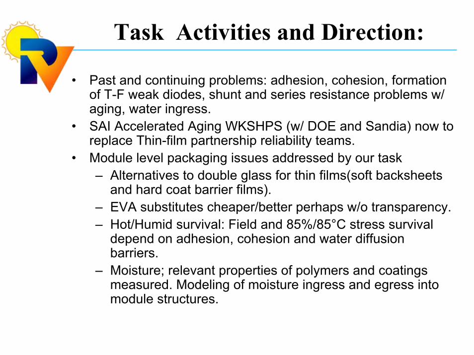
• Past and continuing problems: adhesion, cohesion, formation of T-F weak diodes, shunt and series resistance problems w/ aging, water ingress.
• SAI Accelerated Aging WKSHPS (w/ DOE and Sandia) now to replace Thin-film partnership reliability teams.
• Module level packaging issues addressed by our task– Alternatives to double glass for thin films(soft backsheets
and hard coat barrier films).– EVA substitutes cheaper/better perhaps w/o transparency.– Hot/Humid survival: Field and 85%/85°C stress survival
depend on adhesion, cohesion and water diffusion barriers.
– Moisture; relevant properties of polymers and coatings measured. Modeling of moisture ingress and egress into module structures.
PV Packaging:
• 90% of the field returns * ^• 50% of the PV module cost
* Includes cell interconnects.^ Failure rate and cause depend on how mature the
technology is, e.g. BP Silicon is 1/4200 module year; Newbee modules are 1/10 - 1/100.
Budget / FTEs
$1,413,000 4.85 FTE FY 06
$1,218,000 4.00 FTE FY 07
Talk Outline
Standard adhesion results
Coring/Torque vs Angle Procedure for Adhesion, Cohesion, and Toughness(see Gary Jorgensen’s poster)
DOE outdoor to Accelerated Aging correlation study.
Infrared (3-5 micron) cell and module diagnostics.
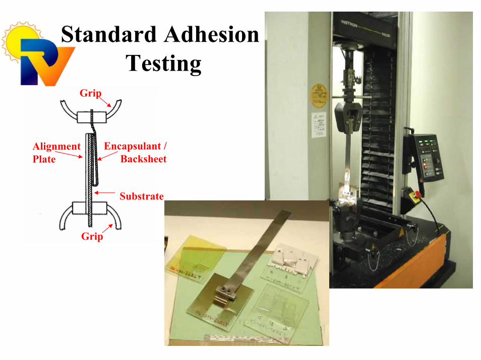
Standard AdhesionTesting
AlignmentPlate
Substrate
Grip
Encapsulant /Backsheet
Grip

Peel Adhesion Testing“Adhesion And Thin-Film Module Reliability,” T.J. McMahon and G.J. Jorgensen, IEEE
Photovoltaic Specialist Conference, May, 2006
• Interface peel strength values of various T-F module technologies. Damp heat stress reduces starting values of 7 N/mm to as little as 0.6 N/mm. Extended UV exposure can also reduce strength.
• Adhesion at higher T’s is greatly reduced: 7 N/mm @ 25° C > 1.1 N/mm @ 60°C >> 0.05 N/mm @ 80° C
– Require a minimum adhesion strength perhaps at higher T and RH.
– The softening of EVA near 85 °C can lead to failure.
• Achieve highest adhesion possible for corrosion and water ingress reduction.
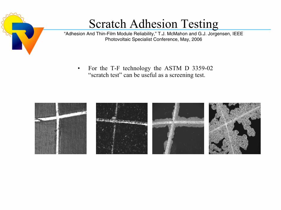
Scratch Adhesion Testing“Adhesion And Thin-Film Module Reliability,” T.J. McMahon and G.J. Jorgensen, IEEE
Photovoltaic Specialist Conference, May, 2006
• For the T-F technology the ASTM D 3359-02 “scratch test” can be useful as a screening test.
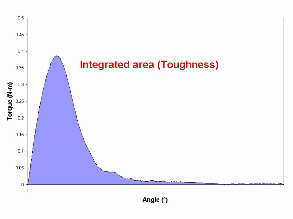
Shear Strength and Toughness
DOE sponsored meeting on “Accelerated Aging Testing in Photovoltaics” Feb 2006
A key recommendation by the attendees was to study a major failure mode and demonstrate that meaningful correlations between field data and accelerated test results could be derived.
Interfaces and layers of weathered PV modules
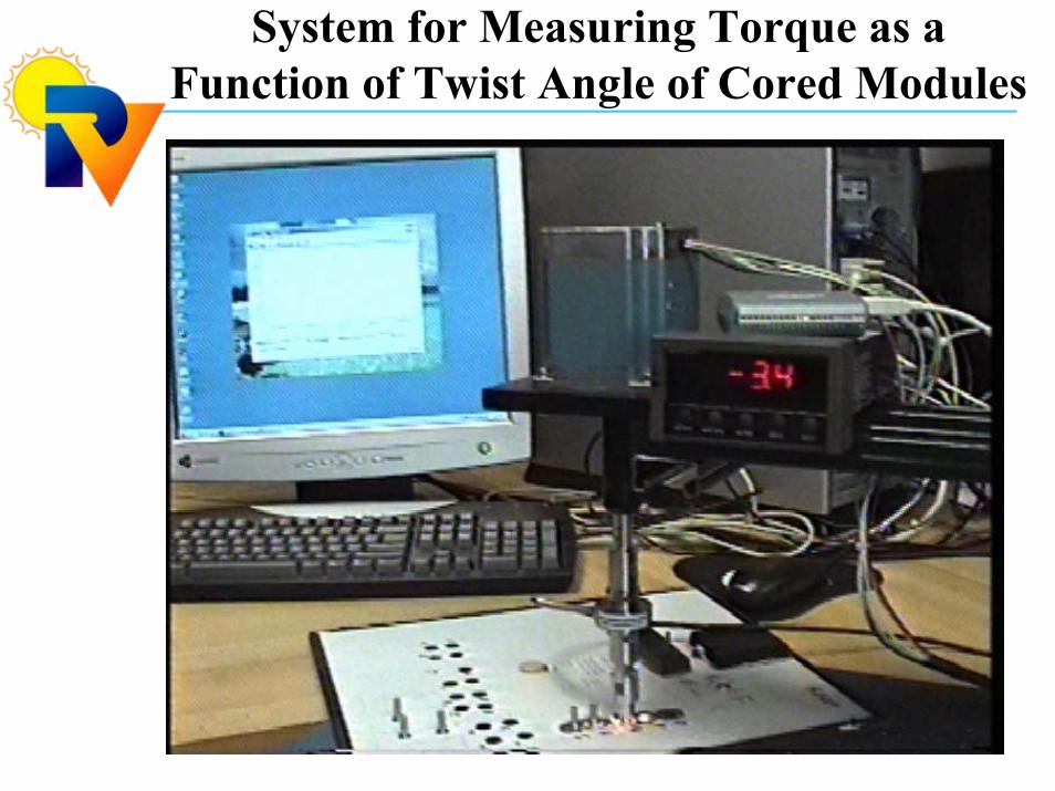
System for Measuring Torque as a Function of Twist Angle of Cored Modules
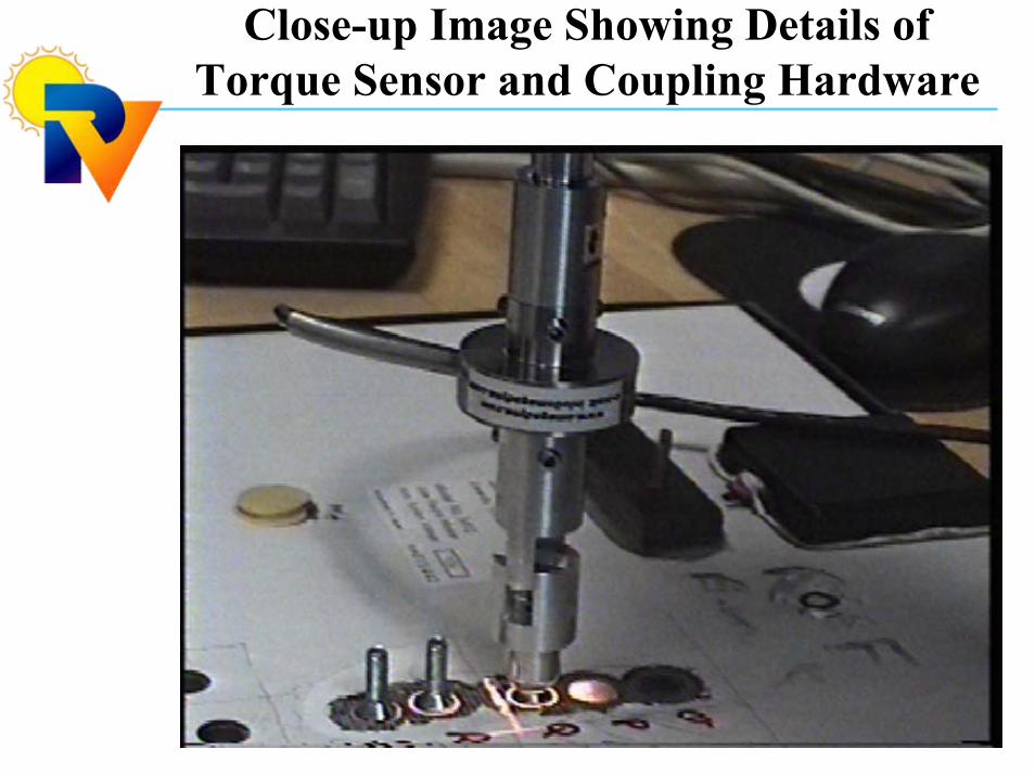
Close-up Image Showing Details of Torque Sensor and Coupling Hardware
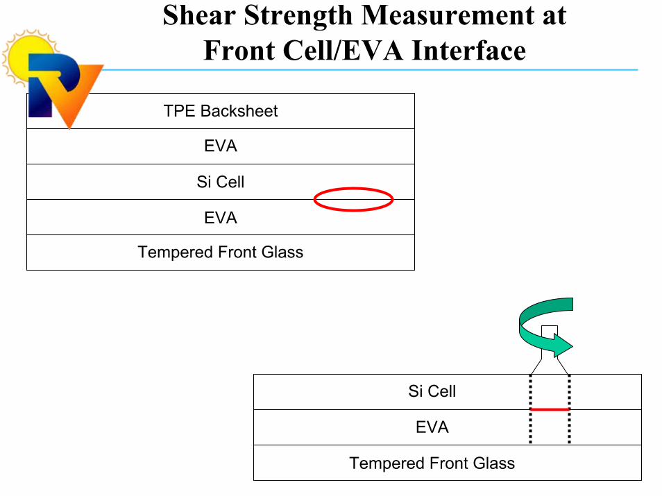
Shear Strength Measurement at Front Cell/EVA Interface
Tempered Front Glass
EVA
Si Cell
EVA
TPE Backsheet
Tempered Front Glass
EVA
Si Cell
Tempered Front Glass
EVA
Si Cell
EVA
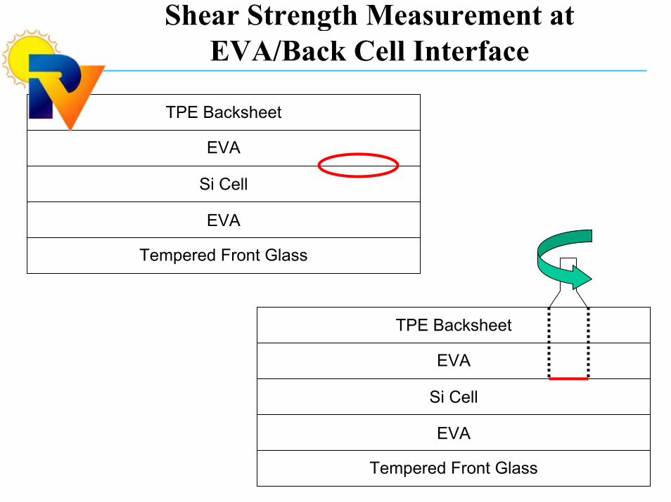
TPE Backsheet
Tempered Front Glass
EVA
Si Cell
EVA
TPE Backsheet
Shear Strength Measurement at EVA/Back Cell Interface

Details of the Cell Coring Process
0
0.1
0.2
0.3
0.4
0.5
0 10 20 30 40
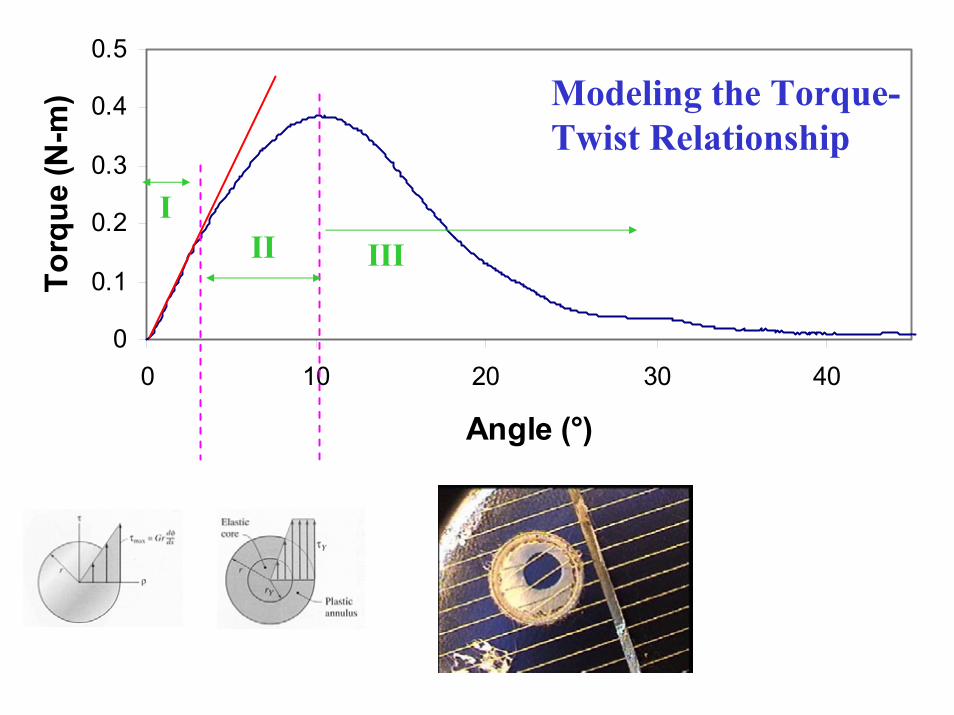
Angle (°)
Torq
ue (N
-m)
III
Modeling the Torque-Twist Relationship
III
C:\Documents and ttings\gjorgens\My D
0
0.1
0.2
0.3
0.4
0.5
0.6
0.7
0 5 10 15 20 25 30 35 40 45
Angle (°)
Torq
ue (N
-m)
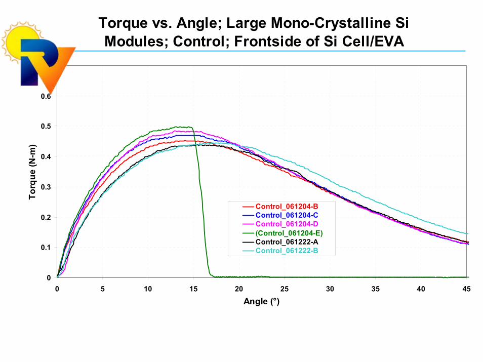
Control_061204-BControl_061204-CControl_061204-D(Control_061204-E)Control_061222-AControl_061222-B
Torque vs. Angle; Large Mono-Crystalline Si Modules; Control; Frontside of Si Cell/EVA
0.00
0.05
0.10
0.15
0.20
0.25
0.30To
ughn
ess
(J-r
ad)
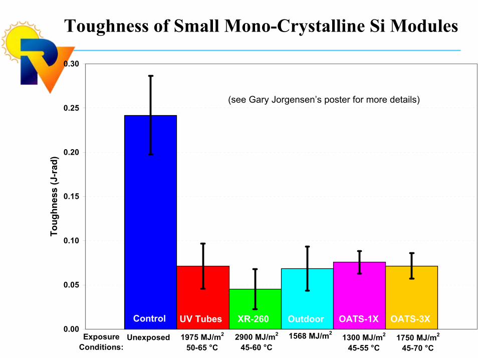
Control UV Tubes XR-260 Outdoor OATS-1X OATS-3X
1975 MJ/m2
50-65 °C2900 MJ/m2
45-60 °C1568 MJ/m2
1300 MJ/m2
45-55 °C1750 MJ/m2
45-70 °CUnexposedExposure
Conditions:
Toughness of Small Mono-Crystalline Si Modules
(see Gary Jorgensen’s poster for more details)
Talk Outline
Standard adhesion results
Coring/Torque vs Angle Procedure for Adhesion, Cohesion, and Toughness(see Gary Jorgensen’s poster)
DOE outdoor to Accelerated Aging correlation study.
Infrared (3-5 micron) cell and module diagnostics.
I-R Image of Cells and Modules
CdTe cell weak diodes(WD).
CIGS module weak diodes, shunts, and series resistance.
CdTe cell WD: IR and IVs
-0.025
-0.02
-0.015
-0.01
-0.005
0
0.005
0.01
0.015
0.02
0.025
-0.2 0 0.2 0.4 0.6 0.8 1
V(volts)
2)
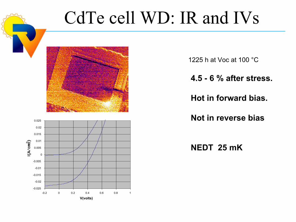
1225 h at Voc at 100 °C
4.5 - 6 % after stress.
Hot in forward bias.
Not in reverse bias
NEDT 25 mK
CdTe cell WD removal
-0.025
-0.02
-0.015
-0.01
-0.005
0
0.005
0.01
0.015
0.02
0.025
-0.2 0 0.2 0.4 0.6 0.8 1
V(volts)
2)
-0.025
-0.02
-0.015
-0.01
-0.005
0
0.005
0.01
0.015
0.02
0.025
-0.2 0 0.2 0.4 0.6 0.8 1
V(volts)
2)
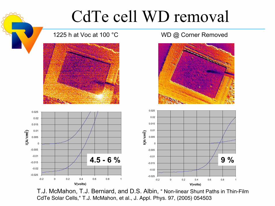
1225 h at Voc at 100 °C WD @ Corner Removed
T.J. McMahon, T.J. Berniard, and D.S. Albin, " Non-linear Shunt Paths in Thin-Film CdTe Solar Cells," T.J. McMahon, et al., J. Appl. Phys. 97, (2005) 054503
9 %4.5 - 6 %
IR images; forward bias
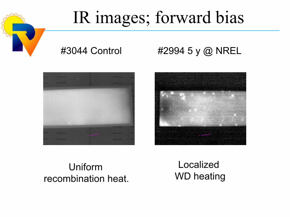
#3044 Control #2994 5 y @ NREL
Uniform recombination heat.
Localized WD heating
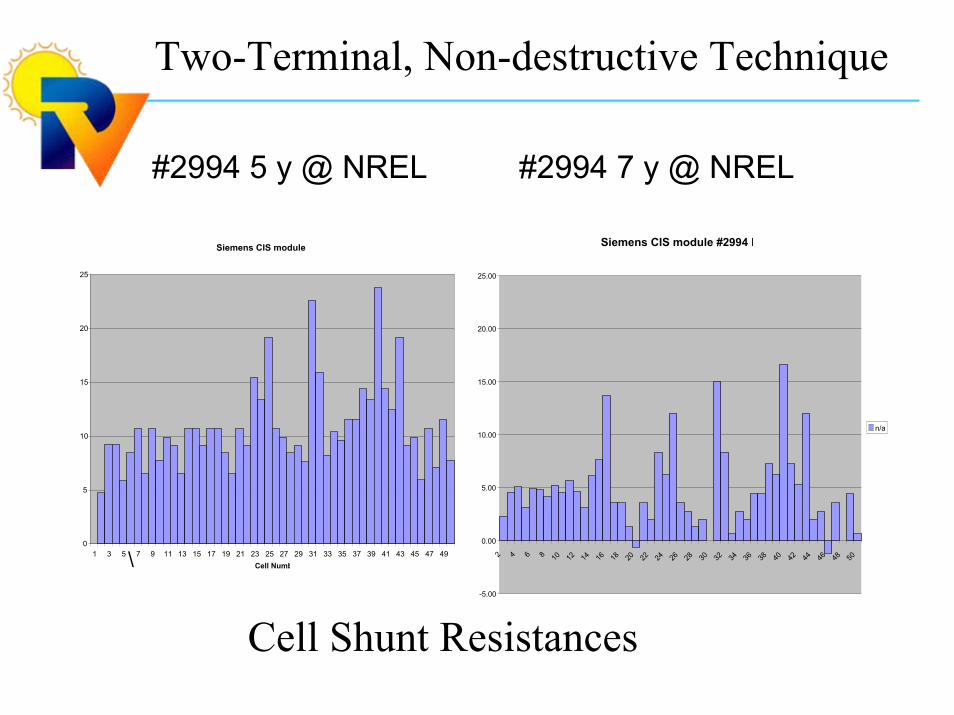
Two-Terminal, Non-destructive Technique
#2994 5 y @ NREL #2994 7 y @ NREL
\
Siemens CIS module #2994 F
-5.00
0.00
5.00
10.00
15.00
20.00
25.00
2 4 6 8 10 12 14 16 18 20 22 24 26 28 30 32 34 36 38 40 42 44 46 48 50
n/a
Siemens CIS module
0
5
10
15
20
25
1 3 5 7 9 11 13 15 17 19 21 23 25 27 29 31 33 35 37 39 41 43 45 47 49Cell Numb
Cell Shunt Resistances
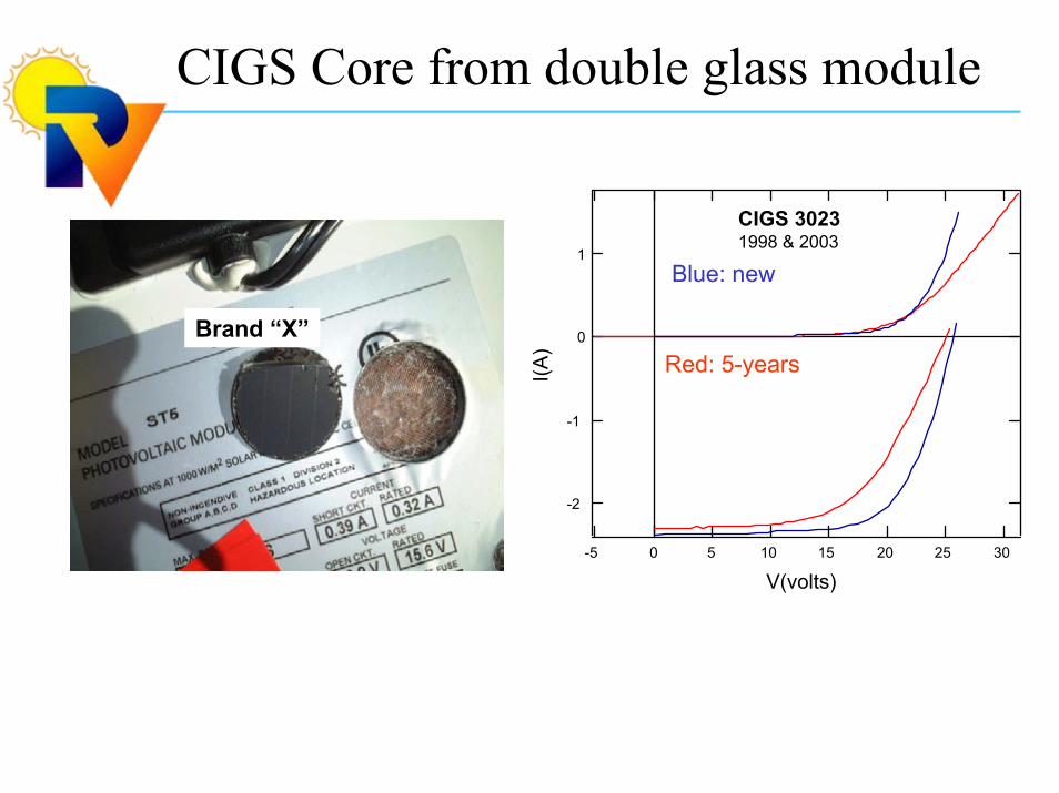
CIGS Core from double glass module
-2
-1
0
1
I(A)
302520151050-5
V(volts)
CIGS 30231998 & 2003
Red: 5-years
Blue: new
Brand “X”
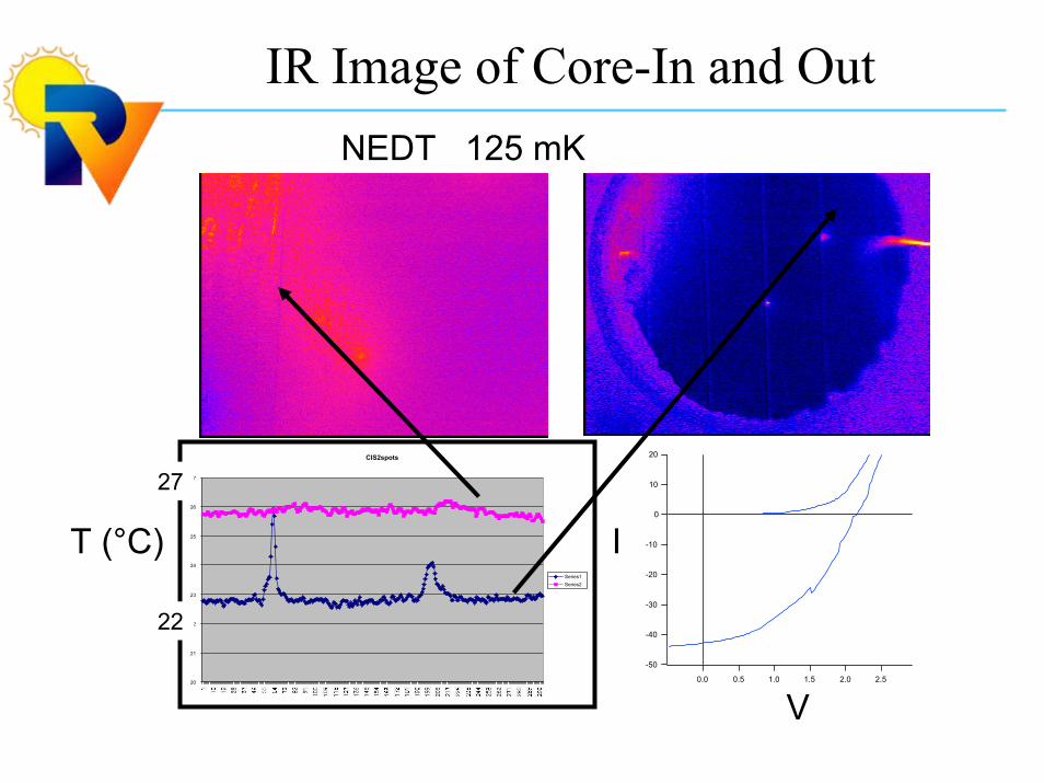
IR Image of Core-In and Out
CIS2spots
20
21
22
23
24
25
26
27
Series1Series2
-50
-40
-30
-20
-10
0
10
20
2.52.01.51.00.50.0
T (°C) I
V
22
27
NEDT 125 mK
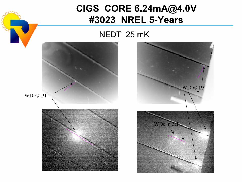
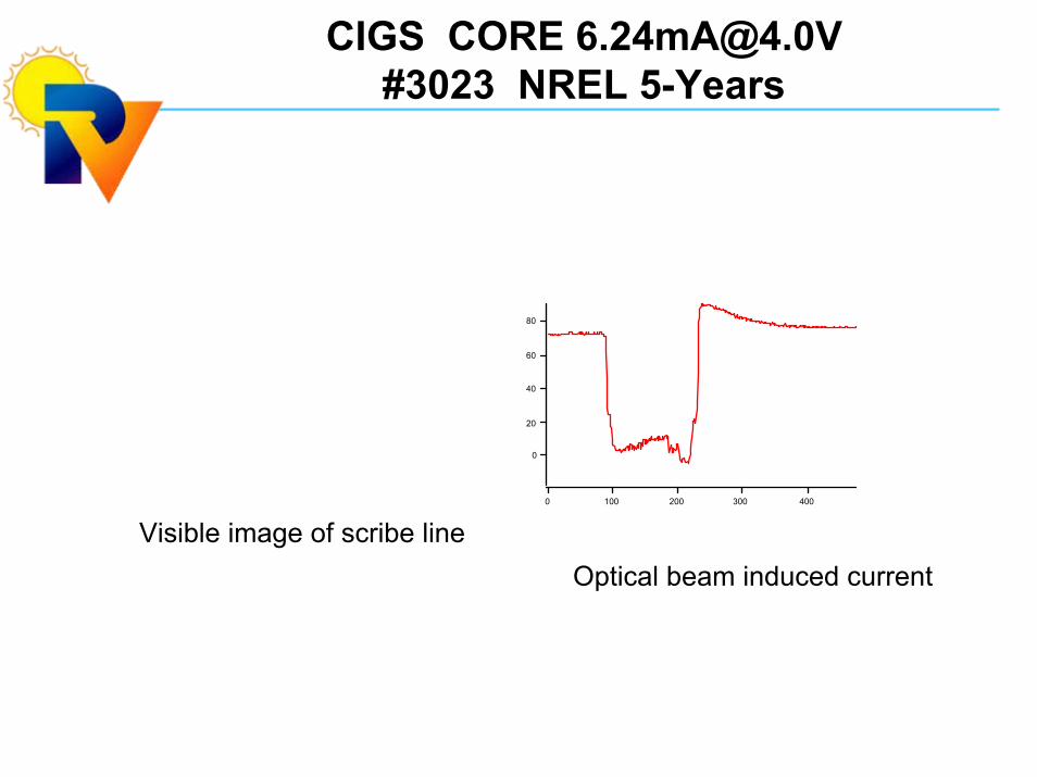
CIGS CORE [email protected]#3023 NREL 5-Years
80
60
40
20
0
4003002001000
Visible image of scribe lineOptical beam induced current

30FS90mA(2mA)@+(-)9.6V20s-zeroDry 85°C, 2280 h
B:Weak-Diodes A:Shunts C:Recom. Area
Forward Bias Reverse Bias

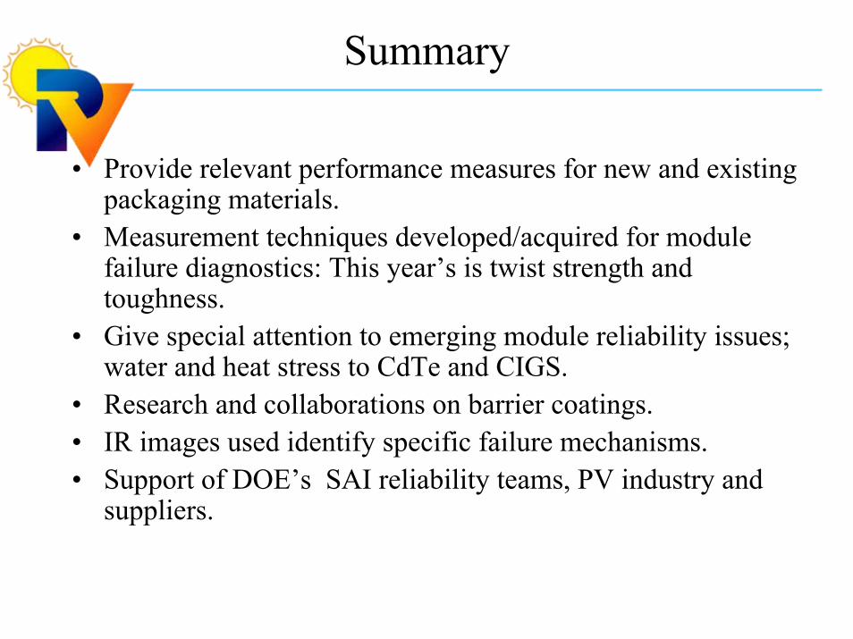
Summary
• Provide relevant performance measures for new and existing packaging materials.
• Measurement techniques developed/acquired for module failure diagnostics: This year’s is twist strength and toughness.
• Give special attention to emerging module reliability issues; water and heat stress to CdTe and CIGS.
• Research and collaborations on barrier coatings.• IR images used identify specific failure mechanisms.• Support of DOE’s SAI reliability teams, PV industry and
suppliers.