ev13, evhp with twido plc and optional thinc … ev13hp manual.pdf · ev13, evhp with twido plc and...
TRANSCRIPT
. P/N: MAN-EV001TC
HIGH PRESSURE/HIGH VOLUME COOLANT SYSTEMS
EV13, EVHP with TWIDO PLC and OPTIONAL THINC® INTERFACE
VARIABLE VOLUME MODELS HIGH PRESSURE / HIGH VOLUME COOLANT DELIVERY SYSTEM
THESE MODELS ARE PROTECTED UNDER UNITED STATES PATENT
NUMBER 5,951,216
INSTALLATION, OPERATION and SERVICE MANUAL ChipBLASTER, Inc. 13605 South Mosiertown Road Meadville, PA 16335 USA www.chipblaster.com Telephone 814-724-6278 Fax 814-724-6287 For your records please list serial number from nameplate ______________ REV C
ChipBLASTER, Inc.
2
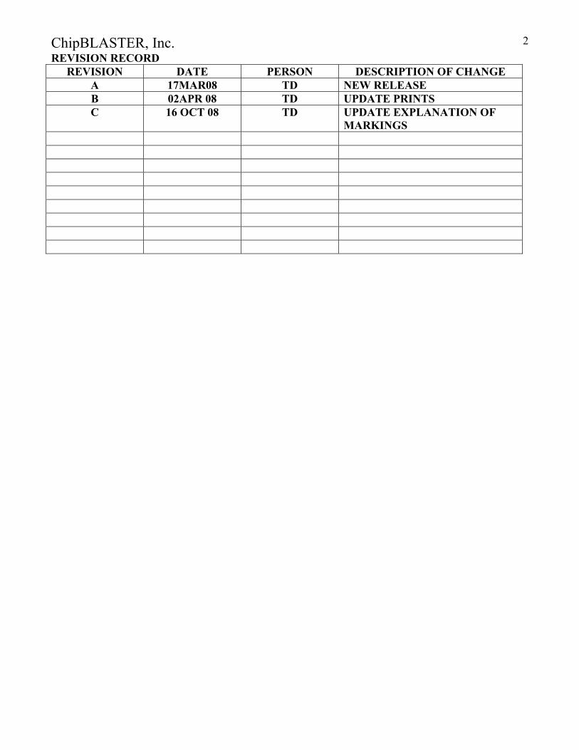
REVISION RECORD REVISION DATE PERSON DESCRIPTION OF CHANGE
A 17MAR08 TD NEW RELEASE B 02APR 08 TD UPDATE PRINTS C 16 OCT 08 TD UPDATE EXPLANATION OF
MARKINGS
ChipBLASTER, Inc.
3
GENERAL:
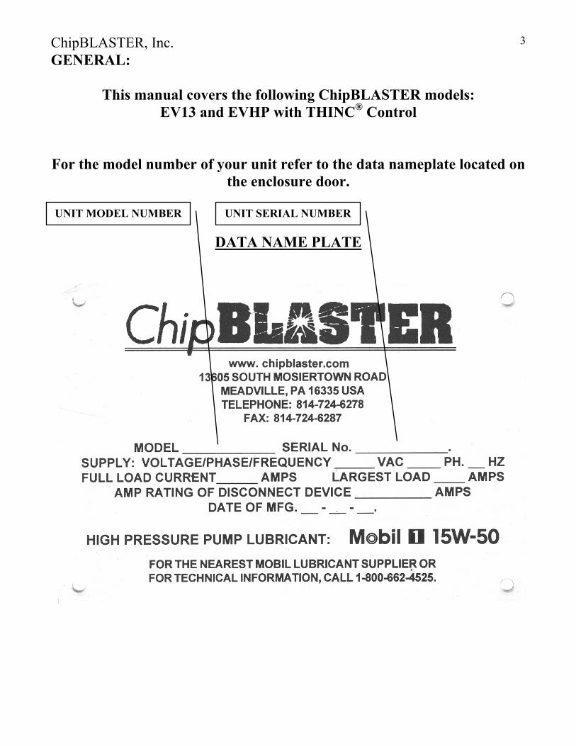
This manual covers the following ChipBLASTER models: EV13 and EVHP with THINC® Control
For the model number of your unit refer to the data nameplate located on the enclosure door.
DATA NAME PLATE
UNIT MODEL NUMBER UNIT SERIAL NUMBER
ChipBLASTER, Inc.
4
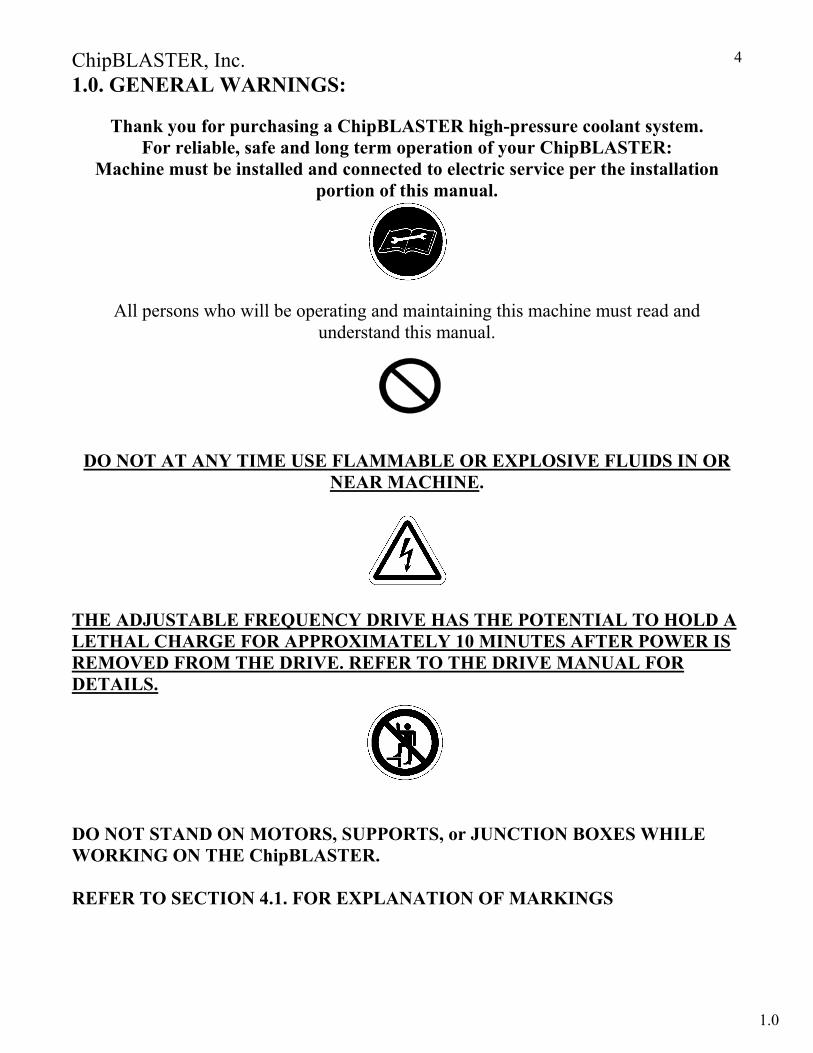
1.0. GENERAL WARNINGS:
Thank you for purchasing a ChipBLASTER high-pressure coolant system. For reliable, safe and long term operation of your ChipBLASTER:
Machine must be installed and connected to electric service per the installation portion of this manual.
All persons who will be operating and maintaining this machine must read and understand this manual.
DO NOT AT ANY TIME USE FLAMMABLE OR EXPLOSIVE FLUIDS IN OR NEAR MACHINE.
THE ADJUSTABLE FREQUENCY DRIVE HAS THE POTENTIAL TO HOLD A LETHAL CHARGE FOR APPROXIMATELY 10 MINUTES AFTER POWER IS REMOVED FROM THE DRIVE. REFER TO THE DRIVE MANUAL FOR DETAILS.
DO NOT STAND ON MOTORS, SUPPORTS, or JUNCTION BOXES WHILE WORKING ON THE ChipBLASTER. REFER TO SECTION 4.1. FOR EXPLANATION OF MARKINGS
1.0

ChipBLASTER, Inc.
5
2.0. TABLE OF CONTENTS: General Page 3
General warnings Section 1.0 Page 4 Table of contents Section 2.0 Page 5 Specifications Section 3.0 Page 9 Safety precautions Section 4.0 Page 11
Explanation of markings Section 4.1 Page 11 Storage Section 5.0 Page 16 Moving machine Section 6.0 Page 16 Placing a ChipBLASTER Section 7.0 Page 17 Mechanical installation Section 8.0 Page 19 Electrical installation Section 9.0 Page 19 Control interface Section 9.1 Page 20 Power connections Section 9.3 Page 20 Start up Section 10.0 Page 20 System air purge Section 11.0 Page 21 Single filter Section 11.1 Page 21 Dual filter Section 11.2 Page 21 Autocross Section 11.3 Page 22 Operation Section 12.0 Page 23
Electrical operation Section 12.1 Page 23 Coolant flow Section 12.2 Page 23 Theory of operation auto cross option Section 12.3 Page 26
Alarms Section 13.0 Page 27 Preventive maintenance Section 14.0 Page 28
Maintenance schedule chart Section 14.1 Page 28 High pressure pump check oil Section 14.2 Page 29
High pressure pump change oil Section 14.3 Page 30 High pressure pump check belt Section 14.4 Page 33 High pressure pump check for leaks Section 14.5 Page 33 High pressure pump rebuild Section 14.6 Page 33 Filter pump - check for leaks Section 14.9 Page 33 Bag filter unit - check pressure gauges Section 14.12 Page 33 Bag filter unit - change filter single filter unit Section 14.13.1 Page 34 Bag filter unit – change filter dual filter-unit shut down Section 14.14 Page 35
2.0

ChipBLASTER, Inc.
6
2.0. TABLE OF CONTENTS (Cont.): Bag filter unit - dual filter unit operating Section 14.15 Page 36
Bag filter unit – autocross unit operating Section 14.16 Page 37 Filter replacement form Section 14.16.13 Page 38
Bag filter unit change filter check for leaks Section 14.17 Page 39 Post filter - changing Section 14.18 Page 39 Sock filter - changing Section 14.19 Page 39 Float switch – cleaning Section 14.23 Page 39
Tank - cleaning Section 14.25 Page 40 Pump mounting bolts – checking Section 14.27 Page 40
Return (transfer) pump – check flow rate Section 14.29 Page 40 Return (transfer) pump – check for leaks Section 14.30 Page 40
Return (transfer) pump – check inlet/outlet Section 14.31 Page 40 LDENS sample line filter - changing Section 14.34 Page 41
Equipment cooling fans – cleaning Section 14.37 Page 41 Troubleshooting Section 15.0 Page 42
Troubleshooting chart Section 15.1 Page 42 Transducer voltage Section 15.2 Page 44 Troubleshooting flow chart Section 15.3 Page 45 Drive error codes – ALTIVAR 31 Drive Section 15.4 Page 46 Drive as set parameters 230 VAC Section 15.8 Page 50 Drive as set parameters 460 VAC Section 15.9 Page 53
Pressure adjustment procedure Section 16.0 Page 56 High pressure pump replacement (single pump) Section 17.0 Page 59 Belt installation Section 18.0 Page 61 Align sprockets Section 18.1 Page 61
Install belt Section 18.2 Page 61 Belt tensioning – General method Section 18.3 Page 61 Belt tensioning – Force deflection method Section 18.4 Page 62 Deflection and force chart Section 18.5 Page 63 System contamination purging procedure Section 19.0 Page 64
Electrical drawings Section 20.0 Page 67 Power wiring schematic Section 20.1 Page 67
Control wiring schematic Section 20.3 Page 68 PLC input wiring Section 20.5 Page 69 PLC output wiring Section 20.7 Page 70
Drive control and power wiring Section 20.9 Page 71 Power and Mistblaster Interface Section 20.13 Page 72
Interface Cable Wiring Section 20.15 Page 73
2.0
ChipBLASTER, Inc.
7
2.0. TABLE OF CONTENTS (Cont.): EV Sub panel layout Section 20.23 Page 74
Schematic piping drawings Section 21.0 Page 75 EV Piping schematic single filter Section 21.1 Page 75 EV Piping schematic dual filters Section 21.2 Page 76 EV Piping schematic autocross filters Section 21.3 Page 77 Mechanical assembly Section 22.0 Page 78 EV Gauge panel side Section 22.1 Page 78 EV Filter side Section 22.6 Page 79 EV Control panel side Section 22.11 Page 80
EV Filter assembly Section 22.16 Page 81 EV Manifold block Section 22.17 Page 82
EV Sub plate plan view Section 22.22 Page 83 EV Oil level site gauge Section 22.27 Page 84 EV Tank plan view
w/ screens and baffles Section 22.28 Page 85 EV Ship loose items Section 22.33 Page 86 EV Spare parts Section 22.38 Page 87 Footprint drawings Section 23.0 Page 88 EV Footprint Section 23.1 Page 88 Warranty Section 24.0 Page 89
Warranty (limited) – New equipment Section 24.1 Page 89 Warranty (limited) – Used equipment Section 24.2 Page 91 Warranty (limited) – Retrofits Section 24.3 Page 93 Warranty claim form Section 24.4 Page 95 Warranty registration card Section 24.5 Page 96 Warranty validation card Section 24.6 Page 97
Optional Equipment Section 27.0 Page 98 Magelis Human machine interface unit Section 27.1 Page 98
Oil skimmer for model without MistBLASTER Section 27.15 Page 101
Magnetic separator Section 27.17 Page 103 Hydrocyclonic filter insert Section 27.18 Page 104 Multiple preset pressures Section 27.19 Page 105 Low pressure wash down option Section 27.20 Page 106
Optional drop in chiller Section 27.21 Page 107
2.0
ChipBLASTER, Inc.
8
2.0. TABLE OF CONTENTS (Cont.): Supplement Data Section 28.0 Page 118
Program revision using EEPROM chip Section 28.1 Page 118 1000 PSI orifice chart Section 28.2 Page 119 1500 PSI orifice chart Section 28.3 Page 120 2000 PSI orifice chart Section 28.4 Page 121
2500 PSI orifice chart Section 28.5 Page 122 3000 PSI orifice chart Section 28.6 Page 123
5000 PSI orifice chart Section 28.7 Page 123
2.0

ChipBLASTER, Inc.
9
3.0. EV13, EVHP SPECIFICATIONS:
3.0
ChipBLASTER, Inc.
10
3.0. SPECIFICATIONS: (Cont.): FCC REGULATIONS: THIS DEVICE COMPLIES WITH PART 15 OF THE FCC RULES. OPERATION IS SUBJECT TO THE FOLLOWING TWO CONDITIONS: (1) THIS DEVICE MAY NOT CAUSE HARMFUL INTERFERENCE, AND (2) THIS DEVICE MUST ACCEPT ANY INTERFERENCE RECEIVED, INCLUDING INTERFERENCE THAT MAY CAUSE UNDESIRED OPERATION. **ALL SPECIFICATIONS, INSTRUCTION, PICTURES, AND ILLUSTRATIONS IN THIS MANUAL ARE BELIEVED TO BE ACCURATE AND MAY CONTAIN CHIPBLASTER INC. PROPRIETARY INFORMATION, WHICH IS PRIVILEGED, CONFIDENTIAL, OR SUBJECT TO COPYRIGHT / PATENT BELONGING TO CHIPBLASTER INC. THIS MANUAL IS INTENDED FOR THE OPERATION AND MAINTENANCE OF YOUR CHIPBLASTER UNIT. YOU ARE HEREBY NOTIFIED THAT ANY DISSEMINATION, DISTRIBUTION, COPYING, OR ACTION TAKEN IN REGARD TO THE CONTENT OF THIS MANUAL IS STRICTLY PROHIBITED AND MAY BE UNLAWFUL. CHIPBLASTER INC. ALSO RESERVES THE RIGHT TO CHANGE THE CONTENTS OF THIS MANUAL WITHOUT NOTICE. IF YOU HAVE ANY QUESTIONS PLEASE CONTACT CHIPBLASTER INC. AT (814) 724-6278.
3.0

ChipBLASTER, Inc.
11
4.0. SAFETY PRECAUTIONS: The items described in these instructions are a very important, so that you can use the ChipBLASTER safely, prevent injury to yourself and other people around you as well as prevent damage to property in the area. Thoroughly familiarize yourself with the symbols and indications shown below and then continue to read the manual. Make sure that you observe all warnings given.
4.1. EXPLANATION of MARKINGS:
Symbols Meaning of Symbols
DANGER
Indicates that error in operation may lead to death or serious injury.
WARNING Indicates that error in operation may lead to injury (*1) to people or that these errors may cause damage to physical property. (*2) *(1) Such things as injury, burns or shock that will require hospitalization or long periods of outpatient treatment. *(2) Physical property damage refers to wide-ranging damage to assets and materials.
PROHIBITED Indicates prohibition (Don’t do it). What is prohibited will be described in or near the symbol in either text or picture form.
!
4.0 - 4.1
ChipBLASTER, Inc.
12
4.1. EXPLANATION of MARKINGS (Cont.):
Symbols (Cont.) Meaning of Symbols
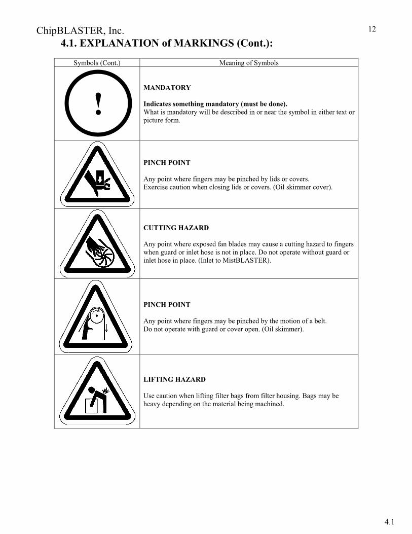
MANDATORY Indicates something mandatory (must be done). What is mandatory will be described in or near the symbol in either text or picture form.
PINCH POINT Any point where fingers may be pinched by lids or covers. Exercise caution when closing lids or covers. (Oil skimmer cover).
CUTTING HAZARD Any point where exposed fan blades may cause a cutting hazard to fingers when guard or inlet hose is not in place. Do not operate without guard or inlet hose in place. (Inlet to MistBLASTER).
PINCH POINT Any point where fingers may be pinched by the motion of a belt. Do not operate with guard or cover open. (Oil skimmer).
LIFTING HAZARD Use caution when lifting filter bags from filter housing. Bags may be heavy depending on the material being machined.
!
4.1
ChipBLASTER, Inc.
13
4.1. EXPLANATION of MARKINGS (Cont.):
Symbols
Meaning of Symbols
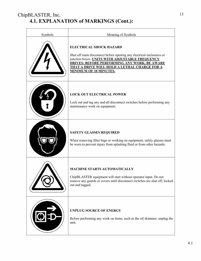
ELECTRICAL SHOCK HAZARD Shut off main disconnect before opening any electrical enclosures or junction boxes. UNITS WITH ADJUSTABLE FREQUENCY DRIVES: BEFORE PERFORMING ANY WORK, BE AWARE THAT A DRIVE WILL HOLD A LETHAL CHARGE FOR A MINIMUM OF 10 MINUTES.
LOCK OUT ELECTRICAL POWER Lock out and tag any and all disconnect switches before performing any maintenance work on equipment.
SAFETY GLASSES REQUIRED When removing filter bags or working on equipment, safety glasses must be worn to prevent injury from splashing fluid or from other hazards.
MACHINE STARTS AUTOMATICALLY ChipBLASTER equipment will start without operator input. Do not remove any guards or covers until disconnect switches are shut off, locked out and tagged.
UNPLUG SOURCE OF ENERGY Before performing any work on items, such as the oil skimmer, unplug the unit.
4.1
ChipBLASTER, Inc.
14
4.1. EXPLANATION of MARKINGS (Cont.):
Symbols (Cont.) Meaning of Symbols (Cont.)
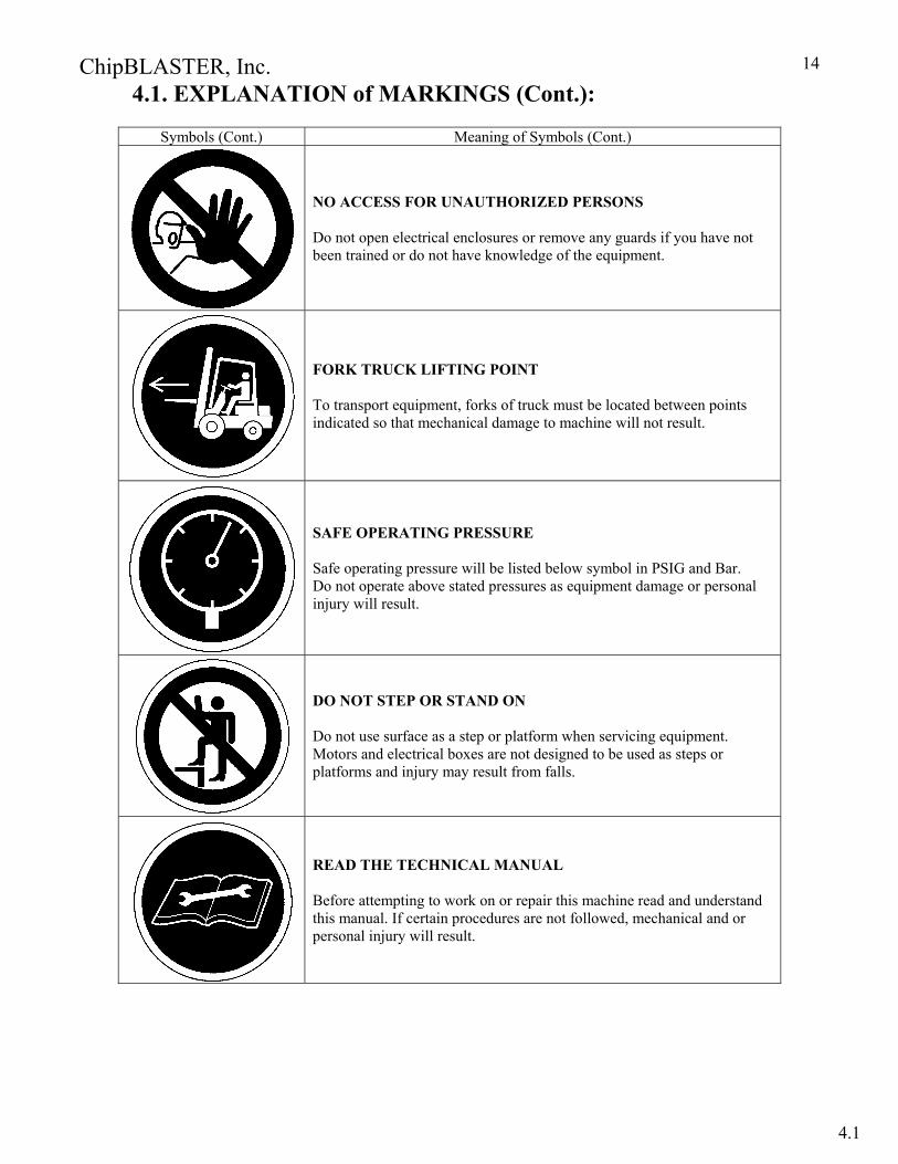
NO ACCESS FOR UNAUTHORIZED PERSONS Do not open electrical enclosures or remove any guards if you have not been trained or do not have knowledge of the equipment.
FORK TRUCK LIFTING POINT To transport equipment, forks of truck must be located between points indicated so that mechanical damage to machine will not result.
SAFE OPERATING PRESSURE Safe operating pressure will be listed below symbol in PSIG and Bar. Do not operate above stated pressures as equipment damage or personal injury will result.
DO NOT STEP OR STAND ON Do not use surface as a step or platform when servicing equipment. Motors and electrical boxes are not designed to be used as steps or platforms and injury may result from falls.
READ THE TECHNICAL MANUAL Before attempting to work on or repair this machine read and understand this manual. If certain procedures are not followed, mechanical and or personal injury will result.
4.1
ChipBLASTER, Inc.
15
4.1. EXPLANATION of MARKINGS (Cont.):
Symbols (Cont.) Meaning of Symbols (Cont.)
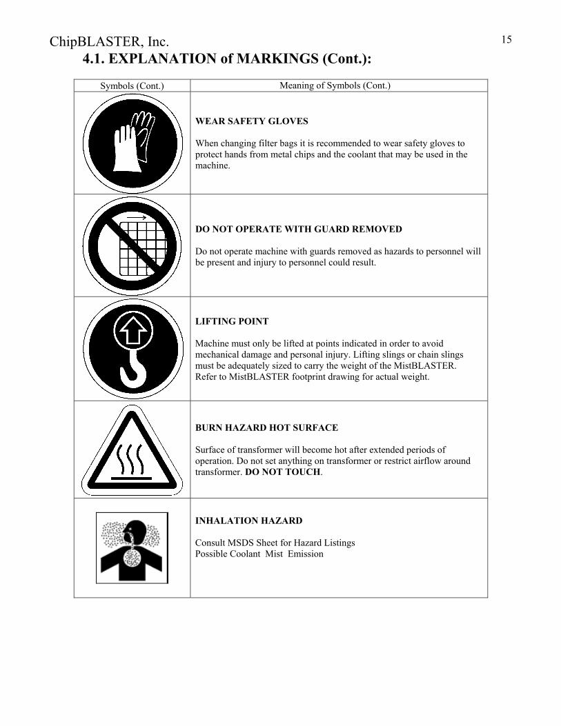
WEAR SAFETY GLOVES When changing filter bags it is recommended to wear safety gloves to protect hands from metal chips and the coolant that may be used in the machine.
DO NOT OPERATE WITH GUARD REMOVED Do not operate machine with guards removed as hazards to personnel will be present and injury to personnel could result.
LIFTING POINT Machine must only be lifted at points indicated in order to avoid mechanical damage and personal injury. Lifting slings or chain slings must be adequately sized to carry the weight of the MistBLASTER. Refer to MistBLASTER footprint drawing for actual weight.
BURN HAZARD HOT SURFACE Surface of transformer will become hot after extended periods of operation. Do not set anything on transformer or restrict airflow around transformer. DO NOT TOUCH.
INHALATION HAZARD Consult MSDS Sheet for Hazard Listings Possible Coolant Mist Emission

ChipBLASTER, Inc.
16
5.0. STORAGE:
5.1. If the ChipBLASTER is to be stored for any period of time it must be keep in an area that is protected from freezing. Freezing temperatures will damage the pumps and the valves. Keep ChipBLASTER covered until ready to move to site. If MistBLASTER is also supplied keep covered.
6.0. MOVING MACHINE:
6.1. When moving the ChipBLASTER to the final site the following must be adhered to: 6.1.1. Lift ChipBLASTER only from the opposite end of the electrical enclosure. Forks must extend the full distance under ChipBLASTER. 6.1.2. The fork truck lifting capacity must be sufficent to safely lift the ChipBLASTER without tipping. Refer to footprint drawing (Section 23) for machine dry weight.
MOVE SLOWLY AS NOT TO DROP THE ChipBLASTER.
DO NOT TRY TO MOVE ChipBLASTER WITH FLUID IN TANK.
DO NOT STAND UNDER ChipBLASTER AT ANY TIME.
If MistBLASTER is supplied with ChipBLASTER: 6.2. When lifting or moving the MistBLASTER, lift only at the eye bolts provided on the top. 6.3. Sling must be of sufficent capacity to safely lift the MistBLASTER.
DO NOT STAND UNDER MistBLASTER AT ANY TIME.
DO NOT MOVE A ChipBLASTER WITH A MistBLASTER MOUNTED ON TOP.
!
!
!
!
!
!
4.1
5.0 - 6.0
!

ChipBLASTER, Inc.
17
7.0. PLACING A ChipBLASTER: 7.1. After you receive your new ChipBLASTER unit the first thing you need to do is prepare
the site where you would like to place the unit. INSTALLATION SITE MUST BE FLAT AND LEVEL.
7.1.1. You need to keep the unit within 10’ of the machining center that you are connecting the ChipBLASTER to. 7.1.2. Locate the unit so the ChipBLASTER’s electrical cabinet is within 15’ of the machining center’s electrical cabinet. 7.1.3. Make sure you place the unit so maintenance can easily get to the filter housing and electrical cabinet on the ChipBLASTER unit. Refer to footprint drawing (Section 23) for recommended clearances.
7.2. After you have the site cleared for the ChipBLASTER unit you are ready to prepare the ChipBLASTER.
7.2.1. Remove the lumber that is used to hold the unit in place during transporation using a phillips screw driver or an electric screw gun. 7.2.2. Before you remove the ChipBLASTER from the skid take a moment and remove the lid from the top of the ChipBLASTER unit. Remove the bag containing the leveling feet. 7.2.3. When removing the ChipBLASTER only from the opposite end of the electrical enclosure. 7.2.4. Insure the forks extend completely under the ChipBLASTER unit to the support.
DO NOT AT ANY TIME REACH UNDER THE ChipBLASTER UNIT OR STAND UNDER THE ChipBLASTER UNIT WHILE IT IS SUPPORTED BY A FORK TRUCK. IF YOU MUST REACH UNDER THE MACHINE BLOCK IT UP FOR SAFETY. 7.2.5. The EV units are shipped from the factory with leveling feet as shown in figure 1a. The leveling feet must be installed when setting up the ChipBLASTER. 7.2.8. After you remove the ChipBLASTER from the skid take the set of four feet and install the studs of the leveling feet through the holes in the legs. Block unit while installing feet for safety. Reference; top of foot to the bottom of second nut (1”). The feet have two functions the first being to level the ChipBLASTER unit and the second being to help eliminate the transfer of noise. Refer to figure 1. 7.2.9. After you have the feet in place proceed with moving the ChipBLASTER into place.
!
!
7 0
ChipBLASTER, Inc.
18
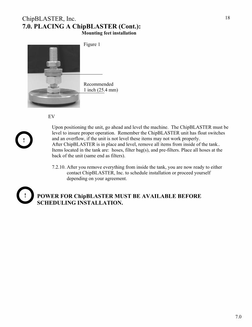
7.0. PLACING A ChipBLASTER (Cont.): Mounting feet installation
Figure 1
Recommended 1 inch (25.4 mm)
EV
Upon positioning the unit, go ahead and level the machine. The ChipBLASTER must be level to insure proper operation. Remember the ChipBLASTER unit has float switches and an overflow, if the unit is not level these items may not work properly. After ChipBLASTER is in place and level, remove all items from inside of the tank.. Items located in the tank are: hoses, filter bag(s), and pre-filters. Place all hoses at the back of the unit (same end as filters). 7.2.10. After you remove everything from inside the tank, you are now ready to either contact ChipBLASTER, Inc. to schedule installation or proceed yourself depending on your agreement.
POWER FOR ChipBLASTER MUST BE AVAILABLE BEFORE SCHEDULING INSTALLATION.
!
!
7.0

ChipBLASTER, Inc.
19
8.0. MECHANICAL INSTALLATION: 8.1. PLUMBING INSTALLATION:
8.1.1. When you are ready to start the installation of the ChipBLASTER unit you first must locate the high-pressure hoses that ChipBLASTER Inc. has provided. Connect the female end to the ChipBLASTER outlet 1 and 2 hoses located on the filter side lower right, then connect the other ends to the machining center (spindle, turret or other designated tool/orifice).
8.1.2. Next you will want to find the 1” clear hose, this will be for the return line. For units that do not have a ChipBLASTER supplied return/transfer pump, connect the 1” clear hose to the 1” inlet on the ChipBLASTER reservoir tank. The other end will connect either to the existing machining center coolant pump. For units that are supplied with a return/transfer pump, connect the 1” clear hose to the inlet of the return/transfer pump and connect the other end to the 1” hose barb of the standpipe assembly after installation on the machine tool sump.
8.1.3. For best use, the inlet of the 1” clear hose in the machining center coolant sump should be approximately 1” from the bottom of the coolant Sump. If using the standpipe assembly position the suction pipe (pipe with 45 degree taper) 1” from bottom of machine tool sump, this should be connected to the inlet of the return/transfer pump.
8.1.4. Connect the 1 1/2” hose to the overflow outlet barb on the side of the ChipBLASTER tank. The other end of this hose should go to the machining center coolant tank. If using the standpipe assembly connect the 1 1/2” to the hose barb.
THE RETURN PUMP MUST BE WITHING 12 FEET OF THE
MACHINING CENTER COOLANT TANK. 9.0. ELECTRICAL INSTALLATION:
INSTALLER MUST COMPLY WITH ALL LOCAL AND NATIONAL ELECTRICAL CODES AND SAFETY GUIDELINES WHEN MAKING ELECTRICAL CONNECTIONS TO THE ChipBLASTER.
REFER TO THE ELECTRICAL DRAWING(S) (SECTION 20) DURING ELECTRICAL INSTALLATION. ALSO REFER TO THE FOOTPRINT DRAWING (SECTION 23) FOR RECOMMENDED WORK CLEARANCE.
BEFORE OPENING THE MACHINING CENTER CABINET DISCONNECT AND LOCKOUT / TAGOUT ALL ELECTRICAL ENERGY SOURCES.
*NOTE-The ChipBLASTER is equipped to accept control interface voltages of 115vac or 24vdc. Please make sure the appropriate control voltage relays are installed in CR1 through CR4. Before applying control power to the unit. The unit is shipped from the factory with 115vac relays installed in CR1, CR2, CR3, CR4. We also include the 24vdc relays loose in the electrical cabinet for interfacing convenience to 24vdc machines.
!
!
!
8.0 – 9.0

ChipBLASTER, Inc.
20
9.0. ELECTRICAL INSTALLATION (Cont.): 9.1. CONTROL INTERFACE EV For Control Interface instructions please refer to The Chipblaster with THINC® Control Installation Procedure received with the Chipblaster. 9.3. POWER SUPPLY CONNECTIONS:
REFER TO ChipBLASTER DATA NAMEPLATE FOR CORRECT SUPPLY VOLTAGE. DO NOT EXCEED AMP RATING OF MACHINING CENTER BREAKER IF CONNECTING TO LOAD SIDE. IF CONNECTING TO A MAIN DROP, SIZE DISCONNECT AND WIRE BASED ON INFORMATION SUPPLIED ON THE ChipBLASTER NAMEPLATE. 9.3.1. The EV is supplied from the factory with a 12 pin plug and receptacle. If the receptacle is not used wire L1, L2 and L3 to the line (top) of the main circuit breaker (1CB). Wire the PE from the machining center to the ground terminal in the ChipBLASTER control panel, otherwise connecL1 to terminal 1, L2 to terminal 2 and L3 to terminal 3. Connect PE to the ground terminal of the receptacle.
10.0. START – UP: 10.1. Fill the ChipBLASTER reservoir with clean coolant to within 3” (76 mm) of top. DO NOT
OVERFILL. 10.1. If machine tool sump is not full, top off as required. DO NOT OVERFILL. 10.2. If ChipBLASTER’s optional return (transfer) pump is used; the pump must be primed. 10.3.1. Remove the fill line form the inlet of the ChipBLASTER tank. 10.3.2. Fill line with clean coolant.
10.3.3. Manually energize return (transfer) pump motor starter (MR3). 10.3.4. The return (transfer) pump should now pull from machine tool sump. 10.3.5. If pump does not pull fluid from machine tool sump repeat the above steps.
CHECK MOTOR ROTATIONS. PLEASE REFER TO BELOW.
CHECK FILTER PUMP ROTATION. ROTATION IS CLOCKWISE VIEWED FROM FAN END
CHECK MAIN PUMP ROTATION. ROTATION IS COUNTER CLOCKWISE VIEWED FROM THE SHAFT END.
CHECK RETURN PUMP ROTATION (IF USED). ROTATION IS CLOCKWISE VIEWED FROM FAN END.
!
!
!
!
!
9.3 – 9.4
9.7 – 9.8
ChipBLASTER, Inc.
21
11.0. SYSTEM AIR PURGE: 11.1. SINGLE FILTER
11.1.1. Open the 1/4” petcock located on both the filter and post filter, so that trapped air can escape both filters. 11.1.2. Press the (RESET / AIR PURGE) push button, to remove the air from the filters. When all of the air has escaped, close the petcocks. This will lower the
tank level and start the return (transfer) pump and lower the sump level. Depending on the capacity of the machine tool sump, the lower level will allow the ChipBLASTER high pressure to fill the sump without overflowing the machine tool sump. Unless the sump is completely emptied DO NOT REFILL MACHINE TOOL SUMP.
11.1.3. Start the ChipBLASTER and check for any coolant leaks. 11.1.4. Insure that all electrical circuits are operating correctly. 11.1.5. The coolant outlet pressure is factory preset to run at 1000 PSIG (69 bar), or a
customer specified pressure. Refer to Pressure Adjustment Procedure. (Section 16.0).11.0. SYSTEM AIR PURGE (Cont.):
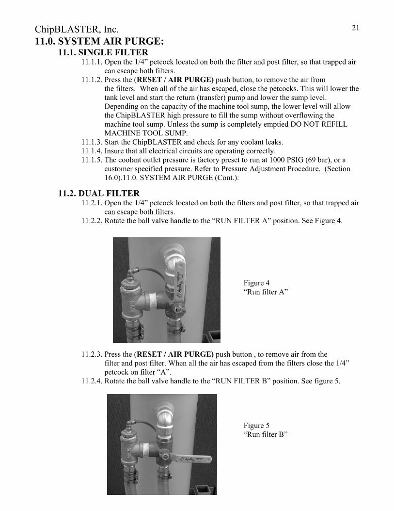
11.2. DUAL FILTER 11.2.1. Open the 1/4” petcock located on both the filters and post filter, so that trapped air
can escape both filters. 11.2.2. Rotate the ball valve handle to the “RUN FILTER A” position. See Figure 4. Figure 4 “Run filter A”
11.2.3. Press the (RESET / AIR PURGE) push button , to remove air from the
filter and post filter. When all the air has escaped from the filters close the 1/4” petcock on filter “A”.
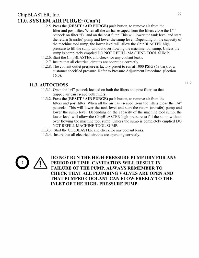
11.2.4. Rotate the ball valve handle to the “RUN FILTER B” position. See figure 5. Figure 5 “Run filter B”
ChipBLASTER, Inc.
22
11.0. SYSTEM AIR PURGE: (Con’t) 11.2.5. Press the (RESET / AIR PURGE) push button, to remove air from the
filter and post filter. When all the air has escaped from the filters close the 1/4” petcock on filter “B” and on the post filter. This will lower the tank level and start the return (transfer) pump and lower the sump level. Depending on the capacity of the machine tool sump, the lower level will allow the ChipBLASTER high pressure to fill the sump without over flowing the machine tool sump. Unless the sump is completely emptied DO NOT REFILL MACHINE TOOL SUMP.
11.2.6. Start the ChipBLASTER and check for any coolant leaks. 11.2.7. Insure that all electrical circuits are operating correctly. 11.2.8. The coolant outlet pressure is factory preset to run at 1000 PSIG (69 bar), or a
customer specified pressure. Refer to Pressure Adjustment Procedure. (Section 16.0).
11.3. AUTOCROSS
11.3.1. Open the 1/4” petcock located on both the filters and post filter, so that trapped air can escape both filters.
11.3.2. Press the (RESET / AIR PURGE) push button, to remove air from the filters and post filter. When all the air has escaped from the filters close the 1/4” petcocks. This will lower the tank level and start the return (transfer) pump and lower the sump level. Depending on the capacity of the machine tool sump, the lower level will allow the ChipBLASTER high pressure to fill the sump without over flowing the machine tool sump. Unless the sump is completely emptied DO NOT REFILL MACHINE TOOL SUMP.
11.3.3. Start the ChipBLASTER and check for any coolant leaks. 11.3.4. Insure that all electrical circuits are operating correctly.
DO NOT RUN THE HIGH-PRESSURE PUMP DRY FOR ANY PERIOD OF TIME. CAVITATION WILL RESULT IN FAILURE OF THE PUMP. ALWAYS REMEMBER TO
CHECK THAT ALL PLUMBING VALVES ARE OPEN AND THAT PUMPED COOLANT CAN FLOW FREELY TO THE INLET OF THE HIGH- PRESSURE PUMP.
!
11.2
ChipBLASTER, Inc.
23
12.0. OPERATION:
12.1. ELECTRICAL OPERATION: 12.1.1. Energizing CR1 will start the automatic operation on the coolant system and
provide coolant out of solenoid #1. At this time the filter pump and the main drive will come on line.
12.1.2. Energizing CR3 (index#1) will stop coolant flow out of solenoid #1 and place the unit into an idle condition. This state is primarily used for tool changes on turning
center applications. 12.1.3. De-energizing CR3 will return the unit to normal operation.
12.1.2. The coolant systems return pump will run automatically and independent of CR1. This pump is controlled through the PLC via the tank level switch.
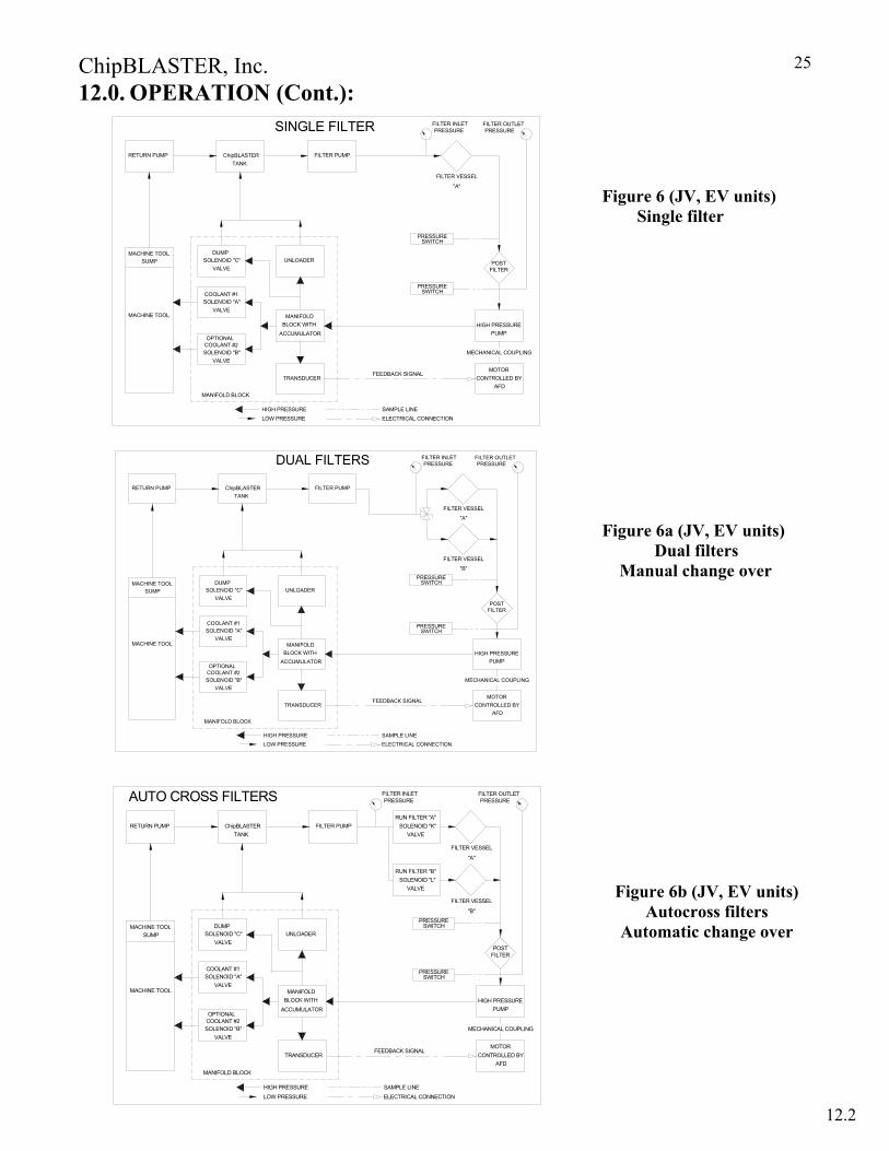
12.2. COOLANT FLOW (Refer to figures 6 through 6b) 12.2.1. Coolant flow is divided into two groups, High-pressure and Low-pressure.
Low- pressure is the flow of coolant from the fourth compartment of the ChipBLASTER’s tank to the high-pressure pump. High-pressure is the flow of
coolant from the high-pressure pump to the nozzle outlet or tool, at the machining center. 12.2.2. LOW-PRESSURE – Low-pressure leaves the fourth compartment of the
ChipBLASTER’s coolant tank and goes to the filter pump. The filter pump pumps the coolant into a large filter where it will be filtered to 5 micron. If a post-filter is used, it will be in series with the larger filter. If the filters gets dirty a flashing red lamp will give an alarm. After filtration, the coolant is then sent through a post filter which is used to protect the high pressure pump in the event the bag filter was incorrectly changed. A steady red light will indicate a dirty post filter. The coolant is sent to the high pressure pump.
12.2.3. HIGH-PRESSURE - High-pressure coolant leaving the pressure pump goes to the manifold block, which consists of an unloader, 3000-psi (206 Bar) pressure gauge, solenoids, transducer, pulsation dampener and a pressure switch (optional). The unloader is adjustable to blow off coolant at 200 psi (13.7 Bar) above the normal running pressure to prevent any over pressure in the high-pressure coolant system. The blow off coolant is then returned to the first compartment in the ChipBLASTER’s tank through a check valve. The dampener unit is installed to dampen the fast changes in coolant pressure. A pressure gauge is installed to read the overall pressure between the high-pressure pump and the nozzle's outlet at the machining center. The transducer reads the overall pressure and produces an error voltage that is fed back to control the speed of the variable drive(1AFD). The optional pressure which is only used to produce an error signal if there is a reduction of pressure below 300 psi (20.6 Bar). The solenoids are used for diverting the coolant for different machine operations. The high-pressure coolant leaves the manifold block and flows through the machining center to the tool being used.
12.1 – 12.2

ChipBLASTER, Inc.
24
12.0. OPERATION (Cont.):
12.2.4. The RETURN (TRANSFER) PUMP is a separate system but is very important. It must maintain the levels of the coolant in the ChipBLASTER’s coolant tank
and the machining center’s coolant tank. The return pump returns coolant from the machining center’s sump to the ChipBLASTER’s coolant tank. The float assembly in the ChipBLASTER’s coolant tank will maintain all coolant levels including the machining center’s sump.
12.2.5. If the ChipBLASTER is to operated from a CENTRAL COOLANT SUPPLY the ChipBLASTER will be supplied with a fill solenoid valve and regulator in place of a return pump. The fill solenoid will operate based on the float assembly in the ChipBLASTER’s coolant tank and will maintain the tank coolant level. The central supply system must be capable of supplying at least 1.5 times the flow rate of the ChipBLASTER model being used. The supply pressure should be in the range of 20 to 30 PSIG (1.4 to 2 bar) The maximum particle size should not exceed 100 micron.
12.2.6. LOW PRESSURE FLOOD is a factory installed feature. It is designed to be used to supply filtered coolant at 5 gpm (18.9 liters/minute) 35 psig (2.4bar) maximum. The flow and pressure is dependent on orifice diameter. The low pressure flood is controlled by a separate maintained “M” code from the machine tool. The low pressure, as supplied from the factory, is available at coolant outlet number 1 and/or 2, depending on ChipBLASTER model. The low pressure flood is used to flush parts, tool plates and general chip clearing. NOTE: If the low pressure flood coolant is in use; high pressure coolant is not available.
12.2.7. HIGH / LOW PRESSURE is available as a factory option if high pressure coolant is required from one coolant outlet and low pressure flood coolant is required from the other coolant outlet at the same time. The low pressure coolant as supplied from the factory is available, as standard, on coolant outlet number 1. NOTE: If HIGH/LOW PRESSURE is required for both coolant outlets a second HIGH/LOW PRESSURE option must be purchased. The low pressure is designed to be used to supply filtered coolant at 5 gpm (18.9 liters/minute) 35 psig (2.4bar) maximum. The flow and pressure is dependent on orifice diameter. The low pressure flood is controlled by a separate maintained “M” code from the machine tool.
12.2.8. LOW PRESSURE HOSE WASH DOWN is also available as an option to provide low pressure filtered coolant through a 20’-0” (6 meter)“garden” hose. Refer to SECTION 27.19 for a complete description of this option.
12.2
ChipBLASTER, Inc.
25
12.0. OPERATION (Cont.): Figure 6 (JV, EV units) Single filter
Figure 6a (JV, EV units) Dual filters Manual change over
Figure Figure 6b (JV, EV units) Autocross filters
Automatic change over
SAMPLE LINEELECTRICAL CONNECTION
FEEDBACK SIGNAL
RETURN PUMP
SUMPMACHINE TOOL
MACHINE TOOL
LOW PRESSUREHIGH PRESSURE
VALVE
OPTIONALCOOLANT #2SOLENOID "B"
MANIFOLD BLOCK
VALVE
SOLENOID "C"
COOLANT #1SOLENOID "A"
VALVE
DUMP
TANKChipBLASTER
ACCUMULATOR
TRANSDUCER
MANIFOLDBLOCK WITH
FILTER PUMP
UNLOADER
MECHANICAL COUPLING
PUMP
MOTORCONTROLLED BY
HIGH PRESSURE
AFD
FILTER VESSEL
SWITCHPRESSURE
"A"
POSTFILTER
SWITCHPRESSURE
SINGLE FILTER FILTER INLET PRESSURE
FILTER OUTLET PRESSURE
MECHANICAL COUPLING
SOLENOID "A"COOLANT #1
SOLENOID "C"
MANIFOLD BLOCK
SOLENOID "B"COOLANT #2
MACHINE TOOL
VALVE
OPTIONAL
MACHINE TOOLSUMP
VALVE
DUMP
VALVE
HIGH PRESSURE
LOW PRESSURE ELECTRICAL CONNECTION
SAMPLE LINE
MANIFOLDBLOCK WITH
TRANSDUCER
ACCUMULATOR
UNLOADER
FEEDBACK SIGNAL
SWITCHPRESSURE
PRESSURESWITCH
ChipBLASTERTANK
RETURN PUMP FILTER PUMP
"A"
FILTER VESSEL
AFDCONTROLLED BY
MOTOR
HIGH PRESSUREPUMP
POSTFILTER
FILTER VESSEL
"B"
DUAL FILTERS FILTER OUTLET PRESSURE
FILTER INLET PRESSURE
POSTFILTER
PUMPHIGH PRESSURE
MOTORCONTROLLED BY
MECHANICAL COUPLING
FILTER VESSEL
MACHINE TOOL
MACHINE TOOL
VALVE
MANIFOLD BLOCK
OPTIONALCOOLANT #2SOLENOID "B"
SUMP
VALVE
COOLANT #1SOLENOID "A"
VALVE
DUMPSOLENOID "C"
LOW PRESSURE
HIGH PRESSURE
ELECTRICAL CONNECTION
SAMPLE LINE
FEEDBACK SIGNAL
MANIFOLD
ACCUMULATOR
TRANSDUCER
BLOCK WITH
UNLOADERSWITCH
PRESSURE
PRESSURESWITCH
"B"
ChipBLASTERRETURN PUMPTANK
FILTER PUMP
FILTER VESSEL
"A"
AFD
RUN FILTER "B"SOLENOID "L"
VALVE
SOLENOID "K"VALVE
RUN FILTER "A"
AUTO CROSS FILTERS FILTER OUTLET PRESSURE
FILTER INLET PRESSURE
12.2
ChipBLASTER, Inc.
26
12.0. OPERATION: (Cont.): 12.3. THEORY OF OPERATION AUTO CROSS OPTION:
12.3.1. The ChipBLASTER is designed to operate with two (2) filters. The ChipBLASTER will typically start on filter A and run until this filter becomes clogged (dirty). When the filter becomes clogged (dirty) the flow will be switched to filter B automatically. The red tower light will begin to flash indicating a clogged (dirty) filter A. The ChipBLASTER will continue to operate.
12.3.2. While the ChipBLASTER is running on filter B, filter A can be changed. (refer to Section 14.9 for procedure) 12.3.3. When the ChipBLASTER is running on filter B and it becomes clogged
(dirty) the ChipBLASTER will go to an emergency stop condition after the “call for coolant” is shut off. This will prevent damage to the high pressure pump.
12.3.4. It should be noted the filter bag A or B is monitored when the ChipBLASTER is operating. The post filter is also monitored when the ChipBLASTER is operating. If the post filter becomes dirty the red tower light will turn on steady.
The reason the post filter can become dirty is do to improper changing of the filter bags. Improper changing will allow chips or contaminates into the bottom of the filter housing which than pass to the post filter. The post filter is designed to prevent chips or contaminates from going through the high pressure pump and damaging the seals. The post filter also prevents chips or contaminates from damaging solenoid vales and pressure switches.
12.3.5. Refer to figure 6b section 12.2 for flow diagram 12.3.6. The autocross units are also equipped to change from filter “A” to “B” after a
timed period. This prevents coolant in filter “B” from becoming stagnate and allowing algae to grow. The ChipBLASTER will start out on filter “A” and after one (1) hour of accumulated run time the flow will be diverted through filter “B”. Filter “B” will be used for twenty (20) minutes and than change back to filter “A”. This cycle will repeat until a filter becomes dirty at which time the timed change over will be stopped until the filters are changed. During the timed change over the filters will still be monitored.
DO NOT ALLOW CHIPS OR CONTAMINATES TO FALL OUT OF FILTER BAGS INTO FILTER HOUSING WHEN CHANGING BAGS.
DO NOT POUR COOLANT FROM BAG INTO FILTER HOUSING, POUR INTO MACHINE TOOL SUMP.
DO NOT POKE HOLES IN BAG WHEN LIFTING OUT OF FILTER HOUSING.
DO REFER TO SECTION 14.9 FOR CORRECT PROCEDURE
FOR CHANGING FILTER BAGS.
DO NOT REUSE DIRTY FILTER BAG.
12.3
12.2

ChipBLASTER, Inc.
27
13.0. ALARMS: 13.1. THE FOLLOWING ERRORS WILL STOP THE OPERATION ON
THE COOLANT SYSTEM AND CAUSE THE ES RELAY TO CHANGE STATES:
13.1.1. Main drive fault. 13.1.2. Filter pump overload. 13.1.3. Return pump overload. 13.1.4. Monitored circuit breaker trip. 13.1.5. Dirty “A” filter at end of cycle. De-energize “call for coolant”.
(Single filter unit). 13.1.6. Dirty “B” filter at end of cycle. De-energize “call for coolant”.
(Auto cross over option). 13.1.7. Dirty post filter at end of cycle. De-energize “call for coolant”.
13.1.8. Low coolant level in the ChipBLASTER coolant tank 13.1.9. High pressure to the machining center is below 300 PSI (20.6 Bar) - (with no
alarm). This requires an optional pressure switch to be purchased with ChipBLASTER.
13.2 . THE FOLLOWING ERRORS WILL CAUSE THE ALARM TO
SOUND: 13.1.1. Any motor overload (constant blast). 13.1.2. Monitored circuit breaker trip (constant blast). 13.1.3. Low coolant limit (intermittent blast). 13.1.4. Post filter for one (1) hour without de-energizing “call for coolant”. 13.1.5. Flow rate of coolant from the machining center’s coolant tank sump to the ChipBLASTER tank is less than 8 GPM [30.2 l/min] (intermittent blast/warning only). SLOW COOLANT RETURN.
13.3. THE FOLLOWING ERROR WILL CAUSE THE ERROR LIGHT TO
FLASH: 13.3.1. Dirty “A” filter either a single, dual or autocross filter system.
13.4. THE FOLLOWING WILL CAUSE THE ERROR LIGHT TO TURN ON STEADY:
13.4.1. Post filter dirty.
13.5. TO RESET A FAULT: 13.5.1. Determine the cause of the fault and correct. Press RESET / AIR PURGE push button on enclosure door. Re-energize the required “M” code to start the ChipBLASTER.
13.0

ChipBLASTER, Inc.
28
14.0. PREVENTATIVE MAINTENANCE: 14.1. PREVENTATIVE MAINTENANCE SCHEDULE:
14.1
ChipBLASTER, Inc.
29
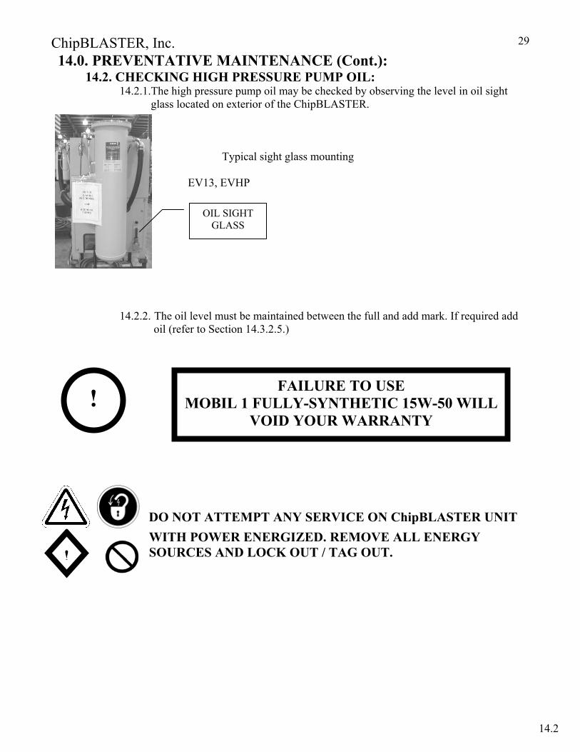
14.0. PREVENTATIVE MAINTENANCE (Cont.): 14.2. CHECKING HIGH PRESSURE PUMP OIL: 14.2.1.The high pressure pump oil may be checked by observing the level in oil sight
glass located on exterior of the ChipBLASTER. Typical sight glass mounting EV13, EVHP
14.2.2. The oil level must be maintained between the full and add mark. If required add oil (refer to Section 14.3.2.5.)
DO NOT ATTEMPT ANY SERVICE ON ChipBLASTER UNIT WITH POWER ENERGIZED. REMOVE ALL ENERGY SOURCES AND LOCK OUT / TAG OUT.
OIL SIGHT GLASS
! FAILURE TO USE MOBIL 1 FULLY-SYNTHETIC 15W-50 WILL
VOID YOUR WARRANTY
!
14.2

ChipBLASTER, Inc.
30
14.0. PREVENTATIVE MAINTENANCE (Cont.): 14.3. OIL CHANGE PROCEDURE:
IT IS EXTREMELY IMPORTANT TO DISCONNECT AND LOCKOUT ANY AND ALL POWER SOURCES BEFORE ANY WORK IS TO BE PERFORMED ON the ChipBLASTER UNIT.
14.3.1. ChipBLASTER High-Pressure Pump: Change the crankcase oil every 2000 hours.
USE: For ChipBLASTER Inc. pump 2106 - Mobil 1 fully-synthetic 15W-50.
Other Pumps and Motors: All have sealed bearings, no lubrication is necessary. 14.3.2. Oil Change Procedure.
14. 3.2.1 ChipBlaster High Pressure pump: Change the crankcase oil every 2000 hrs.
14.3.2.2. Remove accesses panel (use 6mm hex wrench).
Typical access panel
14.3.2.3. Locate OIL SIGHT GAUGE ASSEMBLY and remove plug. (use 8mm hex wrench). Allow to drain into a container. For a single pump unit there will be 32 ounces (0.9 liters) for a two pump unit there will be 64 ounces (1.9 liters). NOTE: In a two pump unit both pumps will be drained at the same time.
FAILURE TO USE MOBIL 1 FULLY-SYNTHETIC 15W-50 WILL
VOID YOUR WARRANTY
!
DRAIN PLUG LOCATION
14.3
ChipBLASTER, Inc.
31
14.0. PREVENTATIVE MAINTENANCE (Cont.): 14.3.2. OIL CHANGE PROCEDURE (Cont.):
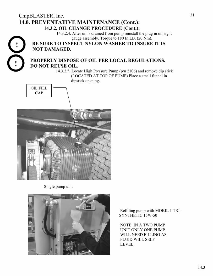
14.3.2.4. After oil is drained from pump reinstall the plug in oil sight gauge assembly. Torque to 180 In LB. (20 Nm). BE SURE TO INSPECT NYLON WASHER TO INSURE IT IS NOT DAMAGED. PROPERLY DISPOSE OF OIL PER LOCAL REGULATIONS. DO NOT REUSE OIL. 14.3.2.5. Locate High Pressure Pump (p/n 2106) and remove dip stick
(LOCATED AT TOP OF PUMP) Place a small funnel in dipstick opening.
Single pump unit
Refilling pump with MOBIL 1 TRI-SYNTHETIC 15W-50 NOTE: IN A TWO PUMP UNIT ONLY ONE PUMP WILL NEED FILLING AS FLUID WILL SELF LEVEL.
!
OIL FILL CAP
!
14.3
ChipBLASTER, Inc.
32
14.0. PREVENTATIVE MAINTENANCE (Cont.): 14.3.2. OIL CHANGE PROCEDURE (Cont.):
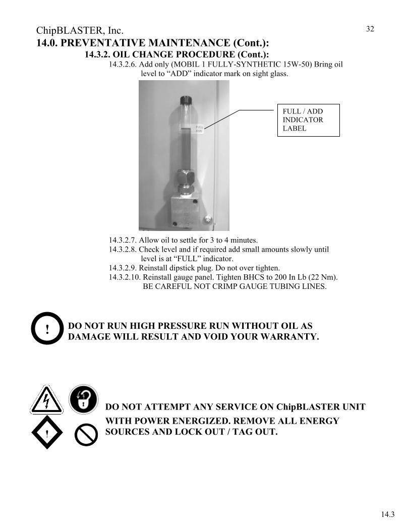
14.3.2.6. Add only (MOBIL 1 FULLY-SYNTHETIC 15W-50) Bring oil level to “ADD” indicator mark on sight glass.
14.3.2.7. Allow oil to settle for 3 to 4 minutes. 14.3.2.8. Check level and if required add small amounts slowly until level is at “FULL” indicator. 14.3.2.9. Reinstall dipstick plug. Do not over tighten.
14.3.2.10. Reinstall gauge panel. Tighten BHCS to 200 In Lb (22 Nm). BE CAREFUL NOT CRIMP GAUGE TUBING LINES.
DO NOT RUN HIGH PRESSURE RUN WITHOUT OIL AS DAMAGE WILL RESULT AND VOID YOUR WARRANTY.
DO NOT ATTEMPT ANY SERVICE ON ChipBLASTER UNIT WITH POWER ENERGIZED. REMOVE ALL ENERGY SOURCES AND LOCK OUT / TAG OUT.
FULL / ADD INDICATOR LABEL
!
!
14.3
ChipBLASTER, Inc.
33
14.0. PREVENTATIVE MAINTENANCE (Cont.): 14.4. HIGH PRESSURE PUMP – CHECK BELT(s):
14.4.1. To check the high pressure pump drive belt, the panel to the left of the gauge panel will need to be removed, using a 6 mm hex wrench.
14.4.2. Check belt tension. Refer to SECTION 18.0. 14.4.3. To adjust motor to pump drive belt turn the adjustment bolt on the pump
mounting base using a 9/16” socket. To tighten belt turn the adjustment screw counter clockwise, to loosen belt, turn the adjustment screw clockwise.
14.4.4. Replace panel before operating the ChipBLASTER.
14.5. HIGH PRESSURE PUMP – CHECK FOR LEAKS: 14.5.1. Remove the panel to the left of the gauge panel using a 6 mm hex wrench. 14.5.2. Check for leaks around pump head and on sub plate. 14.5.3. Verify the fluid is not coming from a fitting or hose. If a hose is leaking shut down the
ChipBLASTER unit and replace hose. If a fitting is leaking, check tightness of fitting. 14.5.4. If fluid is noticed the high pressure pump will require replacement. Contact
ChipBLASTER service department. 14.5.5. Replace gauge panel before operating the ChipBLASTER unit.
14.6. HIGH PRESURE PUMP – REBUILD: 14.6.1. Due to the manufacturing tolerances required for the internal parts of the high
pressure pump, rebuilding the high pressure it is not recommended. A new replacement pump can be purchased from ChipBLASTER. When ordering a new pump from the ChipBLASTER service department, advise the contact person that you wish to receive an RGA number for the pump to be replaced.
14.6.2. When the old pump is received at ChipBLASTER, the pump will be inspected for any damage. If no damage is noted a core charge credit will be issued.
14.9. FILTER PUMP – CHECK FOR LEAKS:
14.9.1. Remove the panel to the left of the gauge panel using a 6 mm hex wrench. 14.9.2. Check for leaks around pump head and on sub plate. 14.9.3. Verify the fluid is not coming from a fitting or hose. If a hose is leaking shut down the
ChipBLASTER unit and replace hose. If a fitting is leaking, check tightness of fitting.
14.12. BAG FILTER UNIT(s): - CHECK PRESSURE GAUGES: 14.12. The inlet and outlet pressure gauges should read within 15 PSI (1 Bar) of each other. If the outlet filter gauge reads less than the inlet gauge this will be an indication of the bag filter becoming clogged. The JV units will indicate a dirty or clogged filter with a flashing red light.
14.4-14.12

ChipBLASTER, Inc.
34
14.0. PREVENTATIVE MAINTENANCE (Cont.): 14.13. FILTER CHANGING PROCEDURE:
USE CARE WHEN CHANGING FILTER BAGS AS THEY MAY BE HEAVY DEPENDING ON MATERIAL BEING MACHINED. THE USE OF GLOVES AND SAFETY GLASSES IS STRONGLY RECOMMENDED DO TO THE CHIPS THAT MAY BE IN THE FILTERS.
DO NOT POKE HOLES IN FILTER BAG WHEN CHANGING. DO NOT DUMP COOLANT FROM FILTER BAGS INTO ChipBLASTER TANK – DUMP COOLANT INTO MACHINE TOOL SUMP. DO NOT REUSE DIRTY FILTER BAGS.
14.0. PREVENTATIVE MAINTENANCE (Cont.): 14.13.1. SINGLE FILTER:
14.13.1.1. A flashing red light will indicate when the bag filter is dirty.
WHEN RUNNING A SINGLE FILTER THE SYSTEM MUST BE TURNED OFF BEFORE CHANGING THE FILTER.
14.13.1.2. Open the air bleed valve to remove any pressure from the filter housing. Then remove the filter lid.
14.13.1.3. Remove lid and inspect for damage. Be careful not to damage filter hold down plate, seal or springs. Set lid aside.
14.13.1.4. Remove optional hydrocyclonic filter (if used) from center of filter bag. 14.13.1.5. Pull the filter bag out of the housing. 14.13.1.6. Install the new filter bag in the housing insure it is all the way down. 14.13.1.6.Install optional hydrocyclonic filter (if used) into the center of filter
bag. 14.13.1.7. Inspect the O-ring for cracks or tears, replace if damaged. 14.13.1.8. Inspect filter hold down seal for cracks or tears, replace if damaged. 14.13.1.9. Make sure the O-ring is in the proper groove before replacing the lid.
Replace the filter lid by setting straight down so that the filter hold down plate will contact filter bag.
14.13.1.10. Torque filter lid cap screws to 30 FT LB (41Nm) in a star pattern. 14.13.1.11. Refer to SECTION 11 START UP FOR FILTER PURGE.
!
14.13
ChipBLASTER, Inc.
35
14.0. PREVENTATIVE MAINTENANCE (Cont.): 14.14. DUAL MANUAL FILTER: (CHIPBLASTER SHUT DOWN) The preferred method is to shut down the ChipBLASTER.
14.14.1. A flashing red light will indicate when the bag filter is dirty. 14.14.2. Open the air bleed valve to remove any pressure from the housing.
Then remove the filter lid. 14.14.3. Remove lid and inspect for damage. Be careful not to damage
filter hold down plate, seal or springs. Set lid aside. 14.14.4. Remove optional hydrocyclonic filter (if used) from center of bag. 14.14.5. Pull the filter bag out of the housing. 14.14.6. Install the new filter bag in the housing insure it is all the way
down. 14.14.7. Replace the optional hydrocyclonic filter (if used). 14.14.8. Inspect the O-ring for cracks or tears, replace if damaged. 14.14.9. Inspect filter hold down seal for cracks or tears, replace if damaged. 14.14.10. Replace the filter lid. Make sure the O-ring is in the proper groove
before replacing the lid. Replace the filter lid by setting straight down so that the filter hold down plate will contact filter bag.
14.14.11. Torque filter lid cap screws to 30 FT LB (41Nm) in a star pattern. 14.14.12. Refer to SECTION 11 START UP FOR FILTER PURGE.
DO NOT POKE HOLES IN FILTER BAG WHEN CHANGING. DO NOT DUMP COOLANT FROM FILTER BAGS INTO ChipBLASTER TANK – DUMP COOLANT INTO MACHINE TOOL SUMP. DO NOT REUSE DIRTY FILTER BAGS.
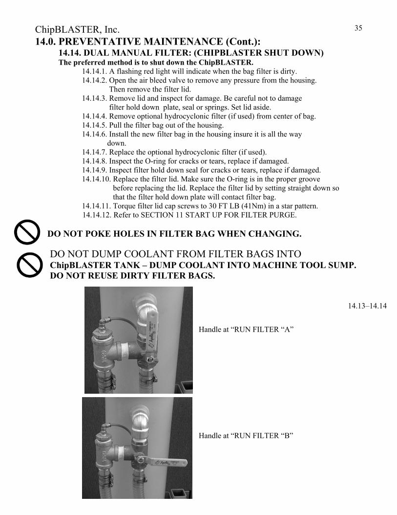
Handle at “RUN FILTER “A” Handle at “RUN FILTER “B”
14.13–14.14
ChipBLASTER, Inc.
36
14.0. PREVENTATIVE MAINTENANCE (Cont.):
14.15. DUAL MANUAL FILTER: (CHIPBLASTER OPERATING) USE EXTREME CAUTION WHEN CHANGING THE FILTER BAG WHILE THE MACHINE IS IN OPERATION.
MAKE SURE TO LOCK OUT THE BALL VALVE TO PREVENT COOLANT FROM COMING THROUGH THE FILTER THAT IS BEING SERVICED. IF THE BALL VALVE IS POSITIONED TO DIRECT FLOW WHILE THE LID IS OFF POTENTIAL PERSONAL INJURY COULD RESULT.
14.15.1. Check the handle of the filter ball valve. If the handle is in the horizontal position (running "B" filter) than it is safe to change filter "A". 14.15.2. If the filter ball valve is in the vertical position (running "A" filter)
then it is safe to change filter "B". 14.15.3. Make sure the air bleed petcocks are opened before changing the filter bag. 14.15.4. Remove lid and inspect for damage. Be careful not to damage filter
hold down plate, seal or springs. Set lid aside. 14.15.5. Remove optional hydrocyclonic filter (if used) from center of bag. 14.15.6. Pull the filter bag out of the housing. 14.15.7. Install the new filter bag in the housing. 14.15.8. Replace the optional hydrocyclonic filter (if used). 14.15.9. Inspect the O-ring for cracks or tears, replace if damaged. 14.15.10. Inspect filter hold down seal for cracks or tears, replace if damaged. 14.15.11. Replace the filter lid. Make sure the O-ring is in the proper groove before
replacing the lid. Replace the filter lid by setting straight down so that the filter hold down plate will contact filter bag.
14.15.12. Torque filter lid cap screws to 30 FT LB (41Nm) in a star pattern. 14.15.13. Refer to SECTION 11 START UP FOR FILTER PURGE.
!
!
14.15
ChipBLASTER, Inc.
37
14.0. PREVENTATIVE MAINTENANCE (Cont.):
14.16. AUTO CROSS OVER: ("A" filter change while unit is in operation).
14.16.1. Change the filter only when the "CHANGE FILTER LIGHT" is flashing.
14.16.2. Place the "CHANGE FILTER" key switch in the change filter position. Remove the key.
14.16.3. Open the "A" filter petcock to make sure there is no pressure coming out of the filter housing.
14.16.4. If air or coolant is coming out of this valve. DO NOT PROCEED, PLEASE CALL THE FACTORY FOR ASSISTANCE.
14.16.5. Remove lid and inspect for damage. Be careful not to damage filter hold down plate, seal or springs. Set lid aside.
14.16.6. Remove optional hydrocyclonic filter (if used) from center of bag. 14.16.7. Pull the filter bag out of the housing. Close the filter air purge petcock. 14.16.8. Install the new filter bag in the housing. 14.16.9. Replace the optional hydrocyclonic filter (if used). 14.16.10. Inspect the O-ring for cracks or tears, replace if damaged. 14.16.11. Inspect filter hold down seal for cracks or tears, replace if damaged. 14.16.12. Replace the filter lid. Make sure the O-ring is in the proper groove before
replacing the lid. Replace the filter lid by setting straight down so that the filter hold down plate will contact filter bag.
14.16.13. Torque filter lid cap screws to 30 FT LB (41Nm) in a star pattern. 14.16.14. Refer to SECTION 11 START UP FOR FILTER PURGE.
DO NOT CHANGE THE "B" FILTER WHILE THE UNIT IS RUNNING. THE "B" FILTER IS USED ONLY AS A BACKUP FILTER TANK TO CHANGE THE "A" FILTER WHILE THE UNIT IS RUNNING.
14.16.11. Both filters can be changed while the unit is shut off. 14.16.12. Refer to SECTION 11 START UP FOR FILTER PURGE after the
filter(s) have been changed.
ChipBLASTER, Inc.
38
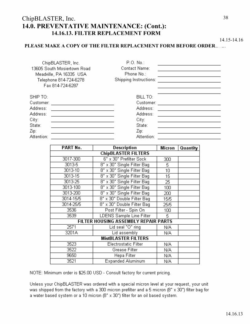
14.0. PREVENTATIVE MAINTENANCE: (Cont.): 14.16.13. FILTER REPLACEMENT FORM
PLEASE MAKE A COPY OF THE FILTER REPLACEMENT FORM BEFORE ORDERING.
14.16.13
14.15-14.16
ChipBLASTER, Inc.
39
14.0. PREVENTATIVE MAINTENANCE: (Cont.): 14.17. FILTER BAG ASSEMBLIES – CHECK FOR LEAKS:
14.17.1. Check inlet and outlet hoses for leaks especially at hose clamps. If leaks are found replace hoses. THE ChipBLASTER MUST BE SHUT DOWN.
14.18. POST FILTER - CHANGING: THIS CAN ONLY BE REPLACED WHEN THE ChipBLASTER IS SHUT DOWN.
14.18.1. Change post filter when the filter light is on steady. 14.18.2. Unscrew and remove the post filter when dirty, 14.18.3. Remove gasket if it does not come off with filter. 14.18.4. Fill the new filter with clean coolant before replacing. This will speed up the
purge time. USE THE SUPPLIED GASKET, install in groove in the post filter mounting base. Screw the filter into place being careful not to cross thread the filter. If the post filter is equipped with a petcock, open the petcock, and press the air purge button, (on the electrical panel), to remove air from
the filter. When all of the air is purged from the filter, close the petcock. 14.19. SOCK FILTER - CHANGING:
14.19.1. This can only be replaced when the ChipBLASTER is shut down. 14.19.2. To remove, cut or untie the cord holding sock filter in place. 14.19.3. Slide the replacement sock filter in place over the fitting and tie securely. 14.19.4. To reorder sock pre-filters refer to form in SCTION 14.16.13.
14.23. FLOAT SWITCH - CLEANING:
14.23.1. Check float switch rod for build up of particulate material, BE CAREFUL NOT TO BEND THE ROD.
14.23.2. If float switch barrel has dirt build up inside it will be necessary to disassemble the switch assembly. 14.23.2.1. Remove the plug from the top using a 3/16” hex key. 14.23.2.2. Unscrew the float bulb from the brass rod. 14.23.2.3. Push the brass rod and magnetic carrier up until the
magnetic carrier can be pulled out of the housing. 14.23.2.4. Clean the barrel of the housing with a round soft bristle
brush. DO NOT LUBRICATE THE FLOAT ASSEMBLY AS THIS WILL CAUSE IMPROPER OPERATION.
14.23.3. Re-assemble float switch. BE CAREFUL NOT TO BEND THE
ROD. 14.23.4. Clean the float bulb also. 14.23.5. After cleaning insure the rod moves up and down freely without
any binding. NOTE: FLOAT STEM CLEANING MAY REQUIRE MORE FREQUENT
CLEANING IF LARGE AMOUNTS OF TRAMP OIL IS PRESENT IN COOLANT RESERVOIR OR CUTTING OILS ARE USED.
!
!
ChipBLASTER, Inc.
40
14.0. PREVENTATIVE MAINTENANCE: (Cont.): 14.25. TANK - CLEANING:
14.25.1. Coolant in the tank should be drained yearly so that the tank may be properly cleaned. 14.25.2. Dispose of fluid per local regulations. 14.25.3. Clean all baffles and replace. 14.25.4. After tank has been cleaned, all filters should be replaced. 14.25.5. The ChipBLASTER should be stated as a new unit. Refer to SECTION 10.0.
14.27. PUMP MOUNTING BOLTS – CHECK: 14.27.1. The filter pump mounting bolts should be checked for tightnes. The
recommended torque is 210 IN LB (24 Newton-meters). 14.27.2. The bolts for the main high pressure prussure pump to mounting rails should be
torqued to 200 IN LB (23 Newton-meters). 14.29. RETURN PUMP (ChipBLASTER supplied) – CHECK FLOW RATE:
14.29.1. This pump should be checked every six months to insure the correct flow rate. If the flow rate has decreased, the pump should be rebuilt or replaced.
14.29.2. An indication the return pump may be clogged will be constant “SLOW COOLANT RETURN” warnings.
14.29.3. The ChipBLASTER must be powered down and the disconnect placed in the OFF position and locked out.
14.29.4. Remove the inlet and outlet hoses by loosening the hose clamps. Inspect the inlet and outlet for chips that may have accumulated, remove chips as required.
14.29.5. Remove the four (4) bolts using a 7/16” wrench that hold the casting in place. 14.29.6. Clean all chips from the casting and impeller. Be careful not to damage the back
of the casting where it mates to the adapter as this is a metal to metal seal. 14.29.7. Re-assemble the casting and replace the four (4) bolts. Insure the casting is
snugly in place. Check the shaft to insure it rotates freely. (Use the screwdriver slot in the motor to turn the shaft).
14.29.8. Re-install the inlet and outlet hoses and tighten the hose clamps securely. 14.29.9. Re-power the ChipBLASTER unit and check for leaks. 14.30. RETURN PUMP (ChipBLASTER supplied) – CHECK FOR LEAKS: 14.30.1. Check for leaks around the casting where it mates with the adapter. 14.30.2. If pump is leaking around casting, tighten the four (4) bolts. DO NOT OVER TIGHTEN. 14.31. RETURN PUMP (ChipBLASTER supplied) – INLET and OUTLET: 14.31.1. Check for leaks around the inlet and outlet connections. 14.31.2. If the hoses are cracked or cut replace hoses.
14.17-14.23
ChipBLASTER, Inc.
41
14.0. PREVENTATIVE MAINTENANCE: (Cont.): 14.34. LDENS SAMPLE LINE FILTER (Used with optional Auto
Concentrate Monitor and Adjust) - CHANGING: THIS CAN ONLY BE REPLACED WHEN THE CHIPBLASTER IS SHUT DOWN. The LDENS filter is not monitored because of the very low flow rate. The cartridge filter should be changed every 30 days under normal conditions. If there is a high volume of way oil (in the case of lathes) the filter should be changed more often. The tell tail signs of a dirty filter cartridge are:
• Erratic density readings (large fluctuations between readings). • A large difference between the percent of concentrate read on a refractometer and the
percentage shown on the HMI. If a large amount of way oil is present in the coolant a good refractometer reading may be difficult.
14.34.1. Power down ChipBLASTER unit. 14.34.2. Depress pressure release button to relieve pressure in filter housing. 14.34.3. Unscrew housing using spanner wrench.
NOTE: When opening filter housing to change cartridge, it is common for o- ring/Gasket to lift out of housing and stick to cap. Remove used cartridge and discard. Rinse out housing and fill about 1/3 full with clean premixed coolant. NOTE: Make sure the o-ring is seated level in the groove (or gasket is on rim of sump). CAUTION: If a ring gasket appears damaged or crimped it should be replaced at this time. Contact ChipBLASTER service for replacement parts.
14.34.4. Insert a new cartridge into the sump making sure that it slips down over the sump standpipe. 14.34.5. Screw the sump onto the cap and hand tighten. DO NOT OVER-TIGHTEN.
Make sure cartridge slips over the cap standpipe. 14.34.6. Turn on power to the ChipBLASTER and energized a call for coolant. Allow the ChipBLASTER to run until the “DELAY BEFORE SAMPLE” timer in the PLC times out and a coolant sample is diverted through the filter. Check for any leaks. The ChipBLASTER may require several samples before the filter housing
and sample line is purged of air. 14.37. EQUIPMENT COOLAING FANS - CLEANING: 14.37.1.To clean the equipment cooling fans, first power down the ChipBLASTER unit
by turning off the main disconnect and locking it out. 14.37.2. Use a soft bristle brush to clean the fan blades. If dirt is caked on it may be
necessary to remove the fan guard to clean, use a mild soap and water with stiff bristle brush to clean the fan blades. Be careful not to damage the fan blades. Replace the fan guards before returning the ChipBLASTER to service.
DO NOT USE COMPRESSED AIR TO CLEAN EQUIPMENT COOLING FANS.
!
14.34-14.37

ChipBLASTER, Inc.
42
15.0. TROUBLESHOOTING: 15.1. TROUBLESHOOTING CHART:
FAULT SYMPTOMS CURE
Chipblaster Has No Power
Disconnect Switch Is Off Turn On Main Power.
Machine Tool Off Turn On Disconnect.
Turn On Machine Tool Overload Tripped Correct Problem, Reset Overload
CR1 Or CR3 Not Energized
No Command Voltage From Machining Center Check Command Voltage
Faulty Relay Replace Relay
High Pressure Motor Not Operating With "CALL FOR COOLANT" (CR1 And Or CR3) Energized
Faulty Transducer Changes Transducer
Faulty Solenoid Change Solenoid
CR1 Or CR7 Not Working Check Circuits
ES Relay De-Energized Correct Problem And Press Reset/Air Purge Pushbutton.
High Pressure Motor Running Slow
CR8 Not Working Check CR8 Circuit
Faulty Transducer Replace Transducer
Faulty Solenoid (Sol A Or B) Replace Solenoid
High Pressure Motor Running Fast
Nozzle To Large Replace Nozzle
Leak In Pressure Line Repair Leak Faulty Transducer Replace Transducer Faulty Solenoid Replace Solenoid Faulty Unloader Check Unloader Faulty AFD Repair AFD
Cannot Achieve Required Outlet Pressure
Pump Seals Are Bad Replace Seals
Faulty Solenoid Replace Solenoid
Faulty Unloader Check Unloader
Incorrect Nozzle Size Replace Nozzle With A Recommended Standard Size.
Unloader Not Set Properly Adjust Unloader Faulty AFD Repair AFD Plugged Or Kinked Hose Replace Coil

ChipBLASTER, Inc.
43
Fault Systems Cure
No Coolant Flowing When High Pressure Is Operating
Solenoid Valve Is Sticking Replace Solenoid
Solenoid Coil Is Faulty Replace Coil
Coolant Is Pulsating From High Pressure Nozzle
High Pressure Pump Valve Is Sticking Clean Or Replace The Valve
Hose Plugged Replace Hose
Coolant Continues To Flow During Tool Changes(Lathes Only)
CR3 Or CR4 Not Working Check Circuit
Solenoid (SOL A Or B) Sticking Change Solenoid
Return Pump Not Operating
MR3 Motor Protector Tripped Or Not Turned On
Reset Breaker
Turn On MR3
Return Pump Coolant Flow Rate Is Slow
Center Float Sticking Free Up Float
Plugged Inlet Clean Inlet
Low On Coolant Add Coolant Chips Stuck Inside Pump Vane Clean Chips From Inside Pump
Motor Wired In Reverse Change Motor Rotation
Coolant Is Foaming Incorrect Coolant Use Coolant With Anti-Foaming Agents For High Pressure
High Pressure Pump Shuts Down After 5 Seconds
Faulty Optional Low Pressure Detect Switch
Replace Low Pressure Detect Switch
Seals Bad In High Pressure Pump
Change High Pressure Pump
Check For Leaks And Repair
ES Relay Not Energized
Motor Overload Trip Reset Motor Overload
AFD Trip Reset Power To AFD
Low Limit Coolant Add Coolant
Circuit Breaker Trip Reset Circuit Breaker
System Won't Operate Loss Of 120VAC Check Transformer, Reset 3CB And Or 4CB
ChipBLASTER, Inc.
44
BEFORE RESETTING AN AFD, CIRCUIT BREAKER OR MOTOR STARTER OVERLOAD – DETERMINE THE CAUSE AND CORRECT FIRST!
IF THE “ES” RELAY TURNS OFF, THE SYSTEM MUST BE RESET.
AFTER THE ERROR IS CLEARED PRESS THE RESET / PURGE PUSHBUTTON ON THE ENCLOSURE DOOR. FOR ADDITIONAL INFORMATION PLEASE CONTACT ChipBLASTER SERVICE DEPARTMENT AT (814) 724-6278. WHEN CONTACTING ChipBLASTER SERVICE DEPARTMENT PLEASE HAVE MODEL AND SERIAL NUMBER OF YOUR ChipBLASTER UNIT. 15.2. TRANSDUCER VOLTAGE:
15.2.1. If calling we would like to know the transducer’s feedback voltage. The information displayed on the digital read-out of the AFD, (Motor Drive), and what the high pressure gauge reading is on the ChipBLASTER’s panel.
15.2.2. ALTIVAR 31 DRIVE To check the Transducer’s feedback voltage, use your meter in the DC mode. Remove the drive control cover. Start the machine and place your Neg lead on The COM terminal. Place your Pos lead on the AI2 terminal and record the reading.
NOTE: Electrical troubleshooting can be done over the phone if you have a qualified
person.
USE EXTREME CAUTION WHEN WORKING INSIDE THE ELECTRICAL ENCLOSURE.
!
!
15.1
!

ChipBLASTER, Inc.
45
15.0. TROUBLESHOOTING (Cont.): 15.3. Troubleshooting Flow Chart
Figure 7
DO YOU HAVE CORRECT PRESSURE AT THE MACHINE TOOL?
YES NODO YOU HAVE PRESSUREON ChipBLASTER's HIGH PRESSURE GAUGE?
YES NO
ChipBLASTER IS OKAY
HIGH PRESSURE GAUGE NOT WORKING
DO YOU HAVE ANYPRESSURE ON ChipBLASTER's HIGH PRESSURE GAUGE?
IS PRESSUREHIGHER OR LOWERTHAN NORMAL?
FAULTY UNLOADER,BYPASS SOLENOIDNOT WORKING, BROKEN BELT
YES NO
LOWERHIGHER
N/C SOLENOID NOTWORKING, NOZZLE PLUGGED WITH CHIPS, NOZZLE TOO SMALL
IS HIGH PRESSUREPUMP RUNNING?
YES NO
NOZZLE OPENING TOO LARGE, LEAKAGE BETWEENChipBLASTER ANDMACHINE TOOL NOZZLE
AFD DRIVE TRIPPED,CR7 NOT ENERGIZED,FAULTY AFD DRIVE,FAULTY MOTOR
TROUBLE SHOOTING FLOW CHART
15.3
ChipBLASTER, Inc.
46
15.0. TROUBLESHOOTING (Cont.): 15.4. ALTIVAR 31 DRIVE (1 AFD) ERROR CODES:
FOR DETAILED INFORMATION ON DRIVE AND / OR FAULTS REFER TO THE SQUARE D ALTIVAR 31 MANUAL
15.4.1. The drive controller can be unlocked after a fault by the following methods:
15.4.1.1. Removing power from the drive controller until the display clears. 15.4.1.2. Automatically, if the automatic restart function is enabled
(PARAMETER Atr IS SET TO YES, SEE PAGE 75 OF THE Altivar31 PROGRAMMING MANUAL).
15.4.1.2. By a logic input, if a logic input is assigned to the fault reset Function. (PARAMETER rSF ASSIGNED TO LI., (SEE PAGE 75 OF THE Altivar31 PROGRAMMING MANUAL).
DO NOT RESET THE INVERTER WHEN TRIPPED BECAUSE OF A FAULT OR ERROR BEFORE ELIMINATING THE PROBLEM THAT CAUSED THE FAULT OR TRIP.
15.4.2 Faults which cannot be automatically reset: 15.4.2.1. Faults which cannot be automatically reset are listed in the table on next page, to clear these faults:
15.4.2.2. Remove power from the drive controller. 15.4.2.3. Wait for the display to go off completely. 15.4.2.4. Determine the cause of the fault and correct it. 15.4.2.5. Reapply power.
bLF, CrF, OCF, SOF, AND tnF CAN ALSO BE RESET REMOTELY VIA A LOGIC INPUT. REFER TO THE RSF PARAMETER ON PAGE 75 OF THE PROGRAMMING MANUAL.
15.4
ChipBLASTER, Inc.
47
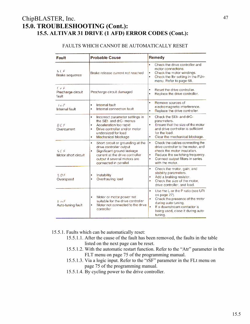
15.0. TROUBLESHOOTING (Cont.): 15.5. ALTIVAR 31 DRIVE (1 AFD) ERROR CODES (Cont.):
FAULTS WHICH CANNOT BE AUTOMATICALLY RESET
15.5.1. Faults which can be automatically reset: 15.5.1.1. After the cause of the fault has been removed, the faults in the table
listed on the next page can be reset. 15.5.1.2. With the automatic restart function. Refer to the “Atr” parameter in the
FLT menu on page 75 of the programming manual. 15.5.1.3. Via a logic input. Refer to the “rSF” parameter in the FLt menu on
page 75 of the programming manual. 15.5.1.4. By cycling power to the drive controller.
15.5

ChipBLASTER, Inc.
48
15.0. TROUBLESHOOTING (Cont.): 15.6. ALTIVAR 31 DRIVE (1 AFD) ERROR CODES (Cont.):
FAULTS WHICH CAN BE AUTOMATICALLY RESET
15.6

ChipBLASTER, Inc.
49
15.0. TROUBLESHOOTING (Cont.): 15.7. ALTIVAR 31 DRIVE (1 AFD) ERROR CODES (Cont.):
FAULTS THAT RESET WHEN THE FAULT IS CLEARED
TURNING THE INVERTER POWER OFF AND THEN ON AGAIN RESETS THE INVERTER IMMEDIATELY. THIS OPERATION MAY DAMAGE THE SYSTEM OR THE MOTOR IF REPEATED.
15.7
ChipBLASTER, Inc.
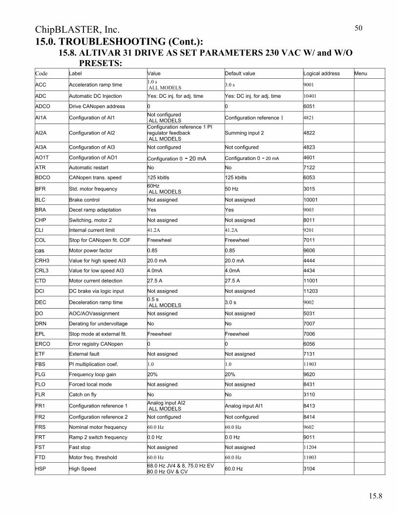
50
15.0. TROUBLESHOOTING (Cont.): 15.8. ALTIVAR 31 DRIVE AS SET PARAMETERS 230 VAC W/ and W/O PRESETS:
Code Label Value Default value Logical address Menu
ACC Acceleration ramp time 1.0 s ALL MODELS 3.0 s 9001
ADC Automatic DC Injection Yes: DC inj. for adj. time Yes: DC inj. for adj. time 10401
ADCO Drive CANopen address 0 0 6051
AI1A Configuration of AI1 Not configured ALL MODELS Configuration reference 1 4821
AI2A Configuration of AI2 Configuration reference 1 PI regulator feedback ALL MODELS
Summing input 2 4822
AI3A Configuration of AI3 Not configured Not configured 4823
AO1T Configuration of AO1 Configuration 0 - 20 mA Configuration 0 - 20 mA 4601
ATR Automatic restart No No 7122
BDCO CANopen trans. speed 125 kbitls 125 kbitls 6053
BFR Std. motor frequency 60Hz ALL MODELS 50 Hz 3015
BLC Brake control Not assigned Not assigned 10001
BRA Decel ramp adaptation Yes Yes 9003
CHP Switching, motor 2 Not assigned Not assigned 8011
CLI Internal current limit 41.2A 41.2A 9201
COL Stop for CANopen fit. COF Freewheel Freewheel 7011
cas Motor power factor 0.85 0.85 9606
CRH3 Value for high speed AI3 20.0 mA 20.0 mA 4444
CRL3 Value for low speed AI3 4.0mA 4.0mA 4434
CTD Motor current detection 27.5 A 27.5 A 11001
DCI DC brake via logic input Not assigned Not assigned 11203
DEC Deceleration ramp time 0.5 s ALL MODELS 3.0 s 9002
DO AOC/AOVassignment Not assigned Not assigned 5031
DRN Derating for undervoltage No No 7007
EPL Stop mode at external fit. Freewheel Freewheel 7006
ERCO Error registry CANopen 0 0 6056
ETF External fault Not assigned Not assigned 7131
FBS PI multiplication coef. 1.0 1.0 11903
FLG Frequency loop gain 20% 20% 9620
FLO Forced local mode Not assigned Not assigned 8431
FLR Catch on fly No No 3110
FR1 Configuration reference 1 Analog input AI2 ALL MODELS Analog input AI1 8413
FR2 Configuration reference 2 Not configured Not configured 8414
FRS Nominal motor frequency 60.0 Hz 60.0 Hz 9602
FRT Ramp 2 switch frequency 0.0 Hz 0.0 Hz 9011
FST Fast stop Not assigned Not assigned 11204
FTD Motor freq. threshold 60.0 Hz 60.0 Hz 11003
HSP High Speed 68.0 Hz JV4 & 8, 75.0 Hz EV 80.0 Hz GV & CV 60.0 Hz 3104
15.8
ChipBLASTER, Inc.
51
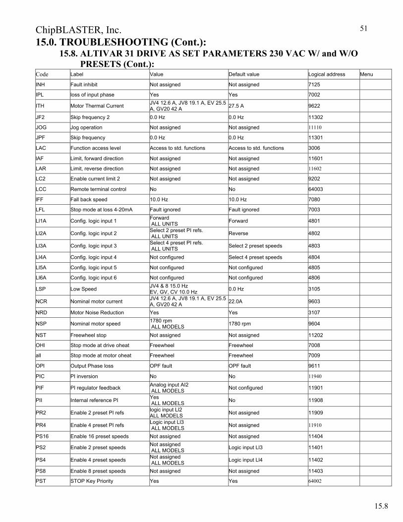
15.0. TROUBLESHOOTING (Cont.): 15.8. ALTIVAR 31 DRIVE AS SET PARAMETERS 230 VAC W/ and W/O PRESETS (Cont.):
Code Label Value Default value Logical address Menu
INH Fault inhibit Not assigned Not assigned 7125
IPL loss of input phase Yes Yes 7002
ITH Motor Thermal Current JV4 12.6 A, JV8 19.1 A, EV 25.5 A, GV20 42 A 27.5 A 9622
JF2 Skip frequency 2 0.0 Hz 0.0 Hz 11302
JOG Jog operation Not assigned Not assigned 11110
JPF Skip frequency 0.0 Hz 0.0 Hz 11301
LAC Function access level Access to std. functions Access to std. functions 3006
lAF Limit, forward direction Not assigned Not assigned 11601
LAR Limit, reverse direction Not assigned Not assigned 11602
LC2 Enable current limit 2 Not assigned Not assigned 9202
LCC Remote terminal control No No 64003
lFF Fall back speed 10.0 Hz 10.0 Hz 7080
LFL Stop mode at loss 4-20mA Fault ignored Fault ignored 7003
Ll1A Config. logic input 1 Forward ALL UNITS Forward 4801
Ll2A Config. logic input 2 Select 2 preset PI refs. ALL UNITS Reverse 4802
Ll3A Config. logic input 3 Select 4 preset PI refs. ALL UNITS Select 2 preset speeds 4803
Ll4A Config. logic input 4 Not configured Select 4 preset speeds 4804
Ll5A Config. logic input 5 Not configured Not configured 4805
Ll6A Config. logic input 6 Not configured Not configured 4806
LSP Low Speed JV4 & 8 15.0 Hz EV, GV, CV 10.0 Hz 0.0 Hz 3105
NCR Nominal motor current JV4 12.6 A, JV8 19.1 A, EV 25.5 A, GV20 42 A 22.0A 9603
NRD Motor Noise Reduction Yes Yes 3107
NSP Nominal motor speed 1780 rpm ALL MODELS 1780 rpm 9604
NST Freewheel stop Not assigned Not assigned 11202
OHl Stop mode at drive oheat Freewheel Freewheel 7008
all Stop mode at motor oheat Freewheel Freewheel 7009
OPl Output Phase loss OPF fault OPF fault 9611
PIC PI inversion No No 11940
PIF PI regulator feedback Analog input AI2 ALL MODELS Not configured 11901
PII Internal reference PI Yes ALL MODELS No 11908
PR2 Enable 2 preset PI refs logic input Ll2 ALL MODELS Not assigned 11909
PR4 Enable 4 preset PI refs Logic input Ll3 ALL MODELS Not assigned 11910
PS16 Enable 16 preset speeds Not assigned Not assigned 11404
PS2 Enable 2 preset speeds Not assigned ALL MODELS Logic input Ll3 11401
PS4 Enable 4 preset speeds Not assigned ALL MODELS Logic input Ll4 11402
PS8 Enable 8 preset speeds Not assigned Not assigned 11403
PST STOP Key Priority Yes Yes 64002
15.8
ChipBLASTER, Inc.
52
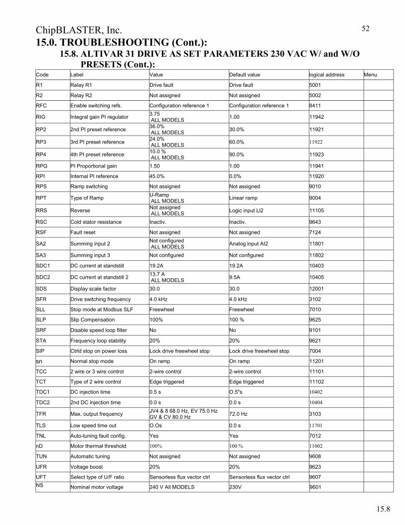
15.0. TROUBLESHOOTING (Cont.): 15.8. ALTIVAR 31 DRIVE AS SET PARAMETERS 230 VAC W/ and W/O PRESETS (Cont.):
Code Label Value Default value logical address Menu
R1 Relay R1 Drive fault Drive fault 5001
R2 Relay R2 Not assigned Not assigned 5002
RFC Enable switching refs. Configuration reference 1 Configuration reference 1 8411
RIG Integral gain PI regulator 3.75 ALL MODELS 1.00 11942
RP2 2nd PI preset reference 36.0% ALL MODELS 30.0% 11921
RP3 3rd PI preset reference 24.0% ALL MODELS 60.0% 11922
RP4 4th PI preset reference 10.0 % ALL MODELS 90.0% 11923
RPG PI Proportional gain 1.50 1.00 11941
RPI Internal PI reference 45.0% 0.0% 11920
RPS Ramp switching Not assigned Not assigned 9010
RPT Type of Ramp U-Ramp ALL MODELS Linear ramp 9004
RRS Reverse Not assigned ALL MODELS Logic input Ll2 11105
RSC Cold stator resistance Inactiv. Inactiv. 9643
RSF Fault reset Not assigned Not assigned 7124
SA2 Summing input 2 Not configured ALL MODELS Analog input AI2 11801
SA3 Summing input 3 Not configured Not configured 11802
SDC1 DC current at standstill 19.2A 19.2A 10403
SDC2 DC current at standstill 2 13.7 A ALL MODELS 9.5A 10405
SDS Display scale factor 30.0 30.0 12001
SFR Drive switching frequency 4.0 kHz 4.0 kHz 3102
SLL Stop mode at Modbus SLF Freewheel Freewheel 7010
SLP Slip Compensation 100% 100 % 9625
SRF Disable speed loop filter No No 9101
STA Frequency loop stability 20% 20% 9621
SIP Ctrld stop on power loss Lock drive freewheel stop Lock drive freewheel stop 7004
sn Normal stop mode On ramp On ramp 11201
TCC 2 wire or 3 wire control 2-wire control 2-wire control 11101
TCT Type of 2 wire control Edge triggered Edge triggered 11102
TDC1 DC injection time 0.5 s O.5"s 10402
TDC2 2nd DC injection time 0.0 s 0.0 s 10404
TFR Max. output frequency JV4 & 8 68.0 Hz, EV 75.0 Hz GV & CV 80.0 Hz 72.0 Hz 3103
TLS Low speed time out O.Os 0.0 s 11701
TNL Auto-tuning fault config. Yes Yes 7012
nD Motor thermal threshold 100% 100 % 11002
TUN Automatic tuning Not assigned Not assigned 9608
UFR Voltage boost 20% 20% 9623
UFT Select type of U/F ratio Sensorless flux vector ctrl Sensorless flux vector ctrl 9607 NS Nominal motor voltage 240 V All MODELS 230V 9601
15.8
ChipBLASTER, Inc.
53
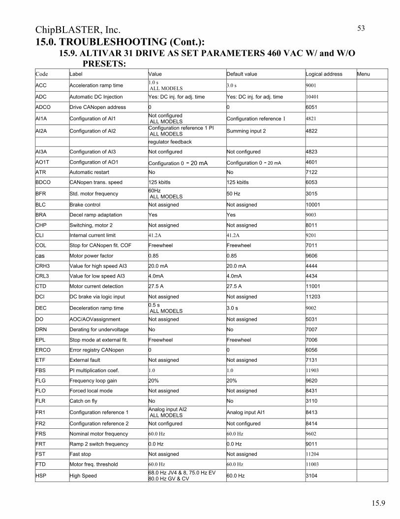
15.0. TROUBLESHOOTING (Cont.): 15.9. ALTIVAR 31 DRIVE AS SET PARAMETERS 460 VAC W/ and W/O
PRESETS: Code Label Value Default value Logical address Menu
ACC Acceleration ramp time 1.0 s ALL MODELS 3.0 s 9001
ADC Automatic DC Injection Yes: DC inj. for adj. time Yes: DC inj. for adj. time 10401
ADCO Drive CANopen address 0 0 6051
AI1A Configuration of AI1 Not configured ALL MODELS Configuration reference 1 4821
AI2A Configuration of AI2 Configuration reference 1 PI ALL MODELS Summing input 2 4822
regulator feedback
AI3A Configuration of AI3 Not configured Not configured 4823
AO1T Configuration of AO1 Configuration 0 - 20 mA Configuration 0 - 20 mA 4601
ATR Automatic restart No No 7122
BDCO CANopen trans. speed 125 kbitls 125 kbitls 6053
BFR Std. motor frequency 60Hz ALL MODELS 50 Hz 3015
BLC Brake control Not assigned Not assigned 10001
BRA Decel ramp adaptation Yes Yes 9003
CHP Switching, motor 2 Not assigned Not assigned 8011
CLI Internal current limit 41.2A 41.2A 9201
COL Stop for CANopen fit. COF Freewheel Freewheel 7011
cas Motor power factor 0.85 0.85 9606
CRH3 Value for high speed AI3 20.0 mA 20.0 mA 4444
CRL3 Value for low speed AI3 4.0mA 4.0mA 4434
CTD Motor current detection 27.5 A 27.5 A 11001
DCI DC brake via logic input Not assigned Not assigned 11203
DEC Deceleration ramp time 0.5 s ALL MODELS 3.0 s 9002
DO AOC/AOVassignment Not assigned Not assigned 5031
DRN Derating for undervoltage No No 7007
EPL Stop mode at external fit. Freewheel Freewheel 7006
ERCO Error registry CANopen 0 0 6056
ETF External fault Not assigned Not assigned 7131
FBS PI multiplication coef. 1.0 1.0 11903
FLG Frequency loop gain 20% 20% 9620
FLO Forced local mode Not assigned Not assigned 8431
FLR Catch on fly No No 3110
FR1 Configuration reference 1 Analog input AI2 ALL MODELS Analog input AI1 8413
FR2 Configuration reference 2 Not configured Not configured 8414
FRS Nominal motor frequency 60.0 Hz 60.0 Hz 9602
FRT Ramp 2 switch frequency 0.0 Hz 0.0 Hz 9011
FST Fast stop Not assigned Not assigned 11204
FTD Motor freq. threshold 60.0 Hz 60.0 Hz 11003
HSP High Speed 68.0 Hz JV4 & 8, 75.0 Hz EV 80.0 Hz GV & CV 60.0 Hz 3104
15.9

ChipBLASTER, Inc.
54
15.0. TROUBLESHOOTING (Cont.): 15.9. ALTIVAR 31 DRIVE AS SET PARAMETERS 460 VAC W/ and W/O
PRESETS (Cont.): Code Label Value Default value Logical address Menu
INH Fault inhibit Not assigned Not assigned 7125
IPL loss of input phase Yes Yes 7002
ITH Motor Thermal Current JV4 12.6 A, JV8 19.1 A, EV 25.5 A, GV20 42 A 27.5 A 9622
JF2 Skip frequency 2 0.0 Hz 0.0 Hz 11302
JOG Jog operation Not assigned Not assigned 11110
JPF Skip frequency 0.0 Hz 0.0 Hz 11301
LAC Function access level Access to std. functions Access to std. functions 3006
lAF Limit, forward direction Not assigned Not assigned 11601
LAR Limit, reverse direction Not assigned Not assigned 11602
LC2 Enable current limit 2 Not assigned Not assigned 9202
LCC Remote terminal control No No 64003
lFF Fall back speed 10.0 Hz 10.0 Hz 7080
LFL Stop mode at loss 4-20mA Fault ignored Fault ignored 7003
Ll1A Config. logic input 1 Forward ALL UNITS Forward 4801
Ll2A Config. logic input 2 Select 2 preset PI refs. ALL UNITS Reverse 4802
Ll3A Config. logic input 3 Select 4 preset PI refs. ALL UNITS Select 2 preset speeds 4803
Ll4A Config. logic input 4 Not configured Select 4 preset speeds 4804
Ll5A Config. logic input 5 Not configured Not configured 4805
Ll6A Config. logic input 6 Not configured Not configured 4806
LSP Low Speed JV4 & 8 15.0 Hz EV, GV, CV 10.0 Hz 0.0 Hz 3105
NCR Nominal motor current JV4 12.6 A, JV8 19.1 A, EV 25.5 A, GV20 42 A 22.0A 9603
NRD Motor Noise Reduction Yes Yes 3107
NSP Nominal motor speed 1780 rpm ALL MODELS 1780 rpm 9604
NST Freewheel stop Not assigned Not assigned 11202
OHl Stop mode at drive oheat Freewheel Freewheel 7008
all Stop mode at motor oheat Freewheel Freewheel 7009
OPl Output Phase loss OPF fault OPF fault 9611
PIC PI inversion No No 11940
PIF PI regulator feedback Analog input AI2 ALL MODELS Not configured 11901
PII Internal reference PI Yes ALL MODELS No 11908
PR2 Enable 2 preset PI refs logic input Ll2 ALL MODELS Not assigned 11909
PR4 Enable 4 preset PI refs Logic input Ll3 ALL MODELS Not assigned 11910
PS16 Enable 16 preset speeds Not assigned Not assigned 11404
PS2 Enable 2 preset speeds Not assigned ALL MODELS Logic input Ll3 11401
PS4 Enable 4 preset speeds Not assigned ALL MODELS Logic input Ll4 11402
PS8 Enable 8 preset speeds Not assigned Not assigned 11403
PST STOP Key Priority Yes Yes 64002
15.9
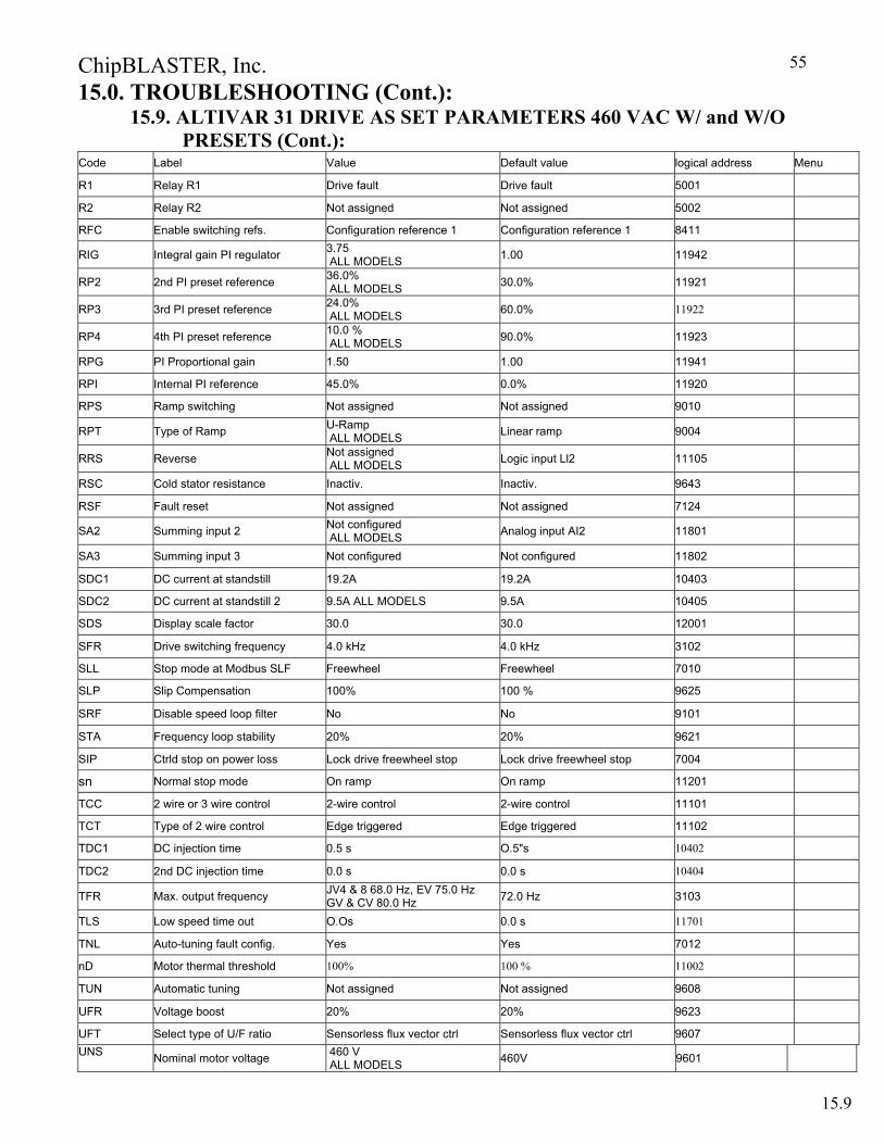
ChipBLASTER, Inc.
55
15.0. TROUBLESHOOTING (Cont.): 15.9. ALTIVAR 31 DRIVE AS SET PARAMETERS 460 VAC W/ and W/O
PRESETS (Cont.): Code Label Value Default value logical address Menu
R1 Relay R1 Drive fault Drive fault 5001
R2 Relay R2 Not assigned Not assigned 5002
RFC Enable switching refs. Configuration reference 1 Configuration reference 1 8411
RIG Integral gain PI regulator 3.75 ALL MODELS 1.00 11942
RP2 2nd PI preset reference 36.0% ALL MODELS 30.0% 11921
RP3 3rd PI preset reference 24.0% ALL MODELS 60.0% 11922
RP4 4th PI preset reference 10.0 % ALL MODELS 90.0% 11923
RPG PI Proportional gain 1.50 1.00 11941
RPI Internal PI reference 45.0% 0.0% 11920
RPS Ramp switching Not assigned Not assigned 9010
RPT Type of Ramp U-Ramp ALL MODELS Linear ramp 9004
RRS Reverse Not assigned ALL MODELS Logic input Ll2 11105
RSC Cold stator resistance Inactiv. Inactiv. 9643
RSF Fault reset Not assigned Not assigned 7124
SA2 Summing input 2 Not configured ALL MODELS Analog input AI2 11801
SA3 Summing input 3 Not configured Not configured 11802
SDC1 DC current at standstill 19.2A 19.2A 10403
SDC2 DC current at standstill 2 9.5A ALL MODELS 9.5A 10405
SDS Display scale factor 30.0 30.0 12001
SFR Drive switching frequency 4.0 kHz 4.0 kHz 3102
SLL Stop mode at Modbus SLF Freewheel Freewheel 7010
SLP Slip Compensation 100% 100 % 9625
SRF Disable speed loop filter No No 9101
STA Frequency loop stability 20% 20% 9621
SIP Ctrld stop on power loss Lock drive freewheel stop Lock drive freewheel stop 7004
sn Normal stop mode On ramp On ramp 11201
TCC 2 wire or 3 wire control 2-wire control 2-wire control 11101
TCT Type of 2 wire control Edge triggered Edge triggered 11102
TDC1 DC injection time 0.5 s O.5"s 10402
TDC2 2nd DC injection time 0.0 s 0.0 s 10404
TFR Max. output frequency JV4 & 8 68.0 Hz, EV 75.0 Hz GV & CV 80.0 Hz 72.0 Hz 3103
TLS Low speed time out O.Os 0.0 s 11701
TNL Auto-tuning fault config. Yes Yes 7012
nD Motor thermal threshold 100% 100 % 11002
TUN Automatic tuning Not assigned Not assigned 9608
UFR Voltage boost 20% 20% 9623
UFT Select type of U/F ratio Sensorless flux vector ctrl Sensorless flux vector ctrl 9607 UNS Nominal motor voltage 460 V
ALL MODELS 460V 9601
15.9
ChipBLASTER, Inc.
56
16.0. PRESSURE ADJUSTMENT PROCEDURE ALTIVAR 31 DRIVES:
This procedure is to be used to adjust the output pressure of the ChipBLASTER high-pressure unit. Please be aware that you must have working knowledge of the complete ChipBLASTER system before making any pressure adjustments. All ChipBLASTER units are shipped out of the factory pre-set at a working pressure of 1000 psi, (68.9 Bar) unless otherwise specified by the end user. This pressure can be read from the high pressure gauge located on the side of the ChipBLASTER unit. Check the machine tool specifications for a maximum operating pressure before proceeding with this procedure.
DO NOT EXCEED THE MANUFACTURERS MAXIMUM OPERATING PRESSURE.
Procedure:
16.0.1. Shut off power to the ChipBLASTER unit. 16.0.2. Locate the Coolant Manifold Assembly under the ChipBLASTER’s coolant tank.
This Manifold Assembly will need to be accessible during this procedure for achieving settings over 1000 psi (68.9 Bar).
16.0.3. Locate coolant outlet #1 (SOL A), and coolant outlet #2 (SOL B), disconnect the solenoid din connector from each solenoid coil.
16.0.4. Repower the ChipBLASTER unit. USE EXTREME CAUTION WHEN WORKING ON LIVE EQUIPMENT. 16.0.5. Energize call for coolant on the machining center.
16.0.6. Locate and adjust the high-pressure unloader using the high-pressure gauge to view the pressure setting. Set the high-pressure unloader 200-psi (13.7 Bar) over the desired working pressure. After the correct adjustment has been made, tighten the lock nut to secure the setting.
TURNING THE UNLOADER ADJUSTMENT ROD (CLOCKWISE) INCREASES THE PRESSURE SETTING OF THE UNLOADER. TURNING THE UNLOADER ADJUSTMENT ROD (COUNTER-CLOCKWISE) DECREASES THE PRESSURE SETTING OF THE UNLOADER.
16.0.7 Turn off high-pressure coolant and power down the ChipBLASTER unit. 16.0.8. Locate coolant outlet #1 (SOL A), and coolant outlet#2 (SOL B), re-connect the
solenoid din connector from each solenoid coil. 16.0.9. Open the enclosure door and locate the adjustable frequency drive (located in the lower left corner of the enclosure).
16.0

ChipBLASTER, Inc.
57
16.0. PRESSURE ADJUSTMENT PROCEDURE ALTIVAR 31 DRIVES: (Cont.)
16.0.10. Turn the main disconnect on to repower the ChipBLASTER unit to alter the
program pressure setting changes to the AFD (Adjustable Frequency Drive).
USE EXTREME CAUTION WHEN WORKING ON LIVE EQUIPMENT.
16.0.11. FOR ALTIVAR 31 DRIVES without setpoints - Adjust the PID setpoint as
follows: 16.0.11.1. At the rdY promp on the display PRESS ENT. SEt will be displayed. 16.0.11.2.Press ENT. rPI will be displayed. 16.0.11.3.Press ENT, 50.0 will be displayed. 16.0.11.4. Press the up or down arrow keys as required to change hertz setting
of the drive. Decreasing the hertz setting will reduce the output pressure like wise increasing the hertz setting will increase the output pressure. Do not exceed the maximum pressure rating of the machine tool.
16.0.11.5. When the revised pressure setting is reached (indicated on the high pressure gauge) PRESS ENT.
16.0.11.6. PRESS ESC three times to return to the rdy screen. NOTE: -Lowering the setpoint will decrease the output pressure.
-Raising the setpoint will increase the output pressure. To view the load on the motor:
With display showing rdY. Press ENT display will show Set. Press the “DOWN” arrow three times until SUP is displayed. Display will show FrH. Press the “DOWN” arrow key four times until LCr is displayed.
This will display the motor current in amps. To return to the rdY display press ESC. DO NOT PRESS ENT.
16.0.11.7. Test run the machine and check the output pressure on the high - pressure gauge and make the necessary adjustments to achieve the
desired working pressure.
16.0
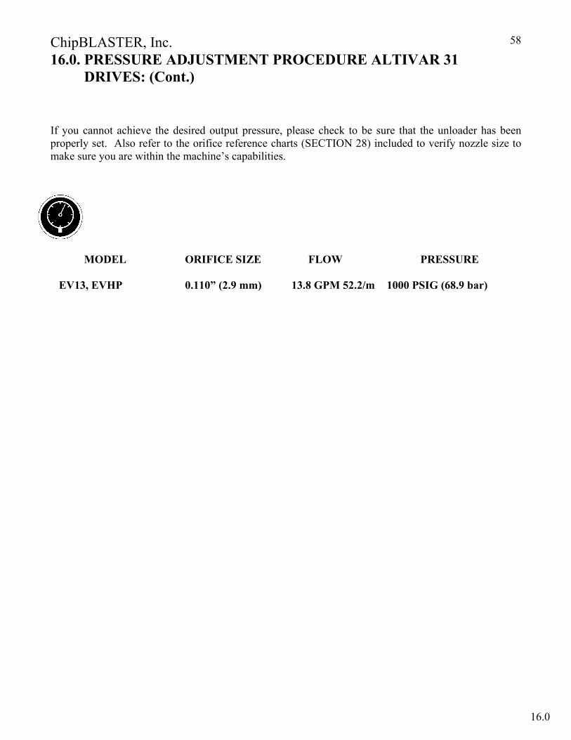
ChipBLASTER, Inc.
58
16.0. PRESSURE ADJUSTMENT PROCEDURE ALTIVAR 31 DRIVES: (Cont.)
If you cannot achieve the desired output pressure, please check to be sure that the unloader has been properly set. Also refer to the orifice reference charts (SECTION 28) included to verify nozzle size to make sure you are within the machine’s capabilities.
MODEL ORIFICE SIZE FLOW PRESSURE EV13, EVHP 0.110” (2.9 mm) 13.8 GPM 52.2/m 1000 PSIG (68.9 bar)
16.0
ChipBLASTER, Inc.
59
17.0. HIGH PRESSURE PUMP REPLACEMENT (SINGLE PUMP):
IT IS EXTREMELY IMPORTANT TO DISCONNECT AND LOCKOUT ANY AND ALL POWER SOURCES BEFORE ANY WORK IS TO BE PERFORMED ON THE
ChipBLASTER UNIT!
17.1. LUBRICATION 17.1.2. After pump replacement procedure, check to insure that the replacement pump crankcase contains oil, and is at the proper level.
Use synthetic Mobil One 15w-50 oil only. Refer to SECTION 14.3.2. for oil filling instructions.
17.2. HYDRAULIC CONNECTIONS AND DRIVE BELT REMOVAL: 17.2.1. Loosen the four mounting bolts, located on the high pressure pump, to allow for
high pressure pump adjustment or drive belt removal. To remove the drive belt, release the belt tension by advancing the high pressure pump forward. Turning the high pressure pump mount adjustment idler counter-clockwise will advance the high pressure pump forward, towards the driven pulley.
17.2.2. Tools required for pump replacement: 17.2.2.1. Pump mounting bolts – 9/16” wrench. 17.2.2.2. Pump mount adjustment idler – 9/16” wrench. 17.2.2.3. Motor drive pulley – 7/16” wrench. 17.2.2.4. JV10, JVHP, GV20, GVHP high pressure fittings – 7/8” wrench. 17.2.2.5. EV13, EVHP high pressure fittings – 1 1/8” wrench. 17.2.2.6. JV10, JVHP, EV13, EVHP, GV20, GVHP low pressure fittings – pipe
wrench. 17.2.2.7. Pump bracket bolts – 5/16” hex key.
DO NOT PRY OR FORCE THE DRIVE BELT OFF OF THE PULLEYS, THIS MAY RESULT IN PERMANENT DAMAGE TO THE PULLEY OR BELT.
ONCE THE DRIVE BELT HAS BEEN REMOVED, VISUALLY INSPECT IT FOR ABNORMAL WEAR AND TOOTH SHEAR. REPLACE THE BELT AS NECESSARY.
!
!
17.0
ChipBLASTER, Inc.
60
17.0. HIGH PRESSURE PUMP REPLACEMENT (SINGLE PUMP): (Cont.):
17.3. THE REPLACEMENT PUMP: 17.3.1. Remove the low pressure hose, high pressure hose, oil line hose, black
drain line lines and the pulley from the defective pump. Remove the 4 bolts that secure the pump to the rails and remove the defective pump.
17.3.2. Install the replacement pump on the rails using the hardware removed in step 17.3.1. above.
17.3.3. Install the pulley (DO NOT TIGHTEN), low pressure hose, high pressure hose, oil line hose, black drain line on the replacement pump. NOTE: The upper port is the high pressure port and the lower port is the low pressure port.
17.3.4. Torque all of the hex and square plumbing fittings to 36ft/lbs. (48.8 Nm). Using a straightedge to line up the pulleys on the pump and motor. Tighten pulley set screws.
17.3.5. Torque bushing bolts to 108 in lb (12.2 Nm).
17.0
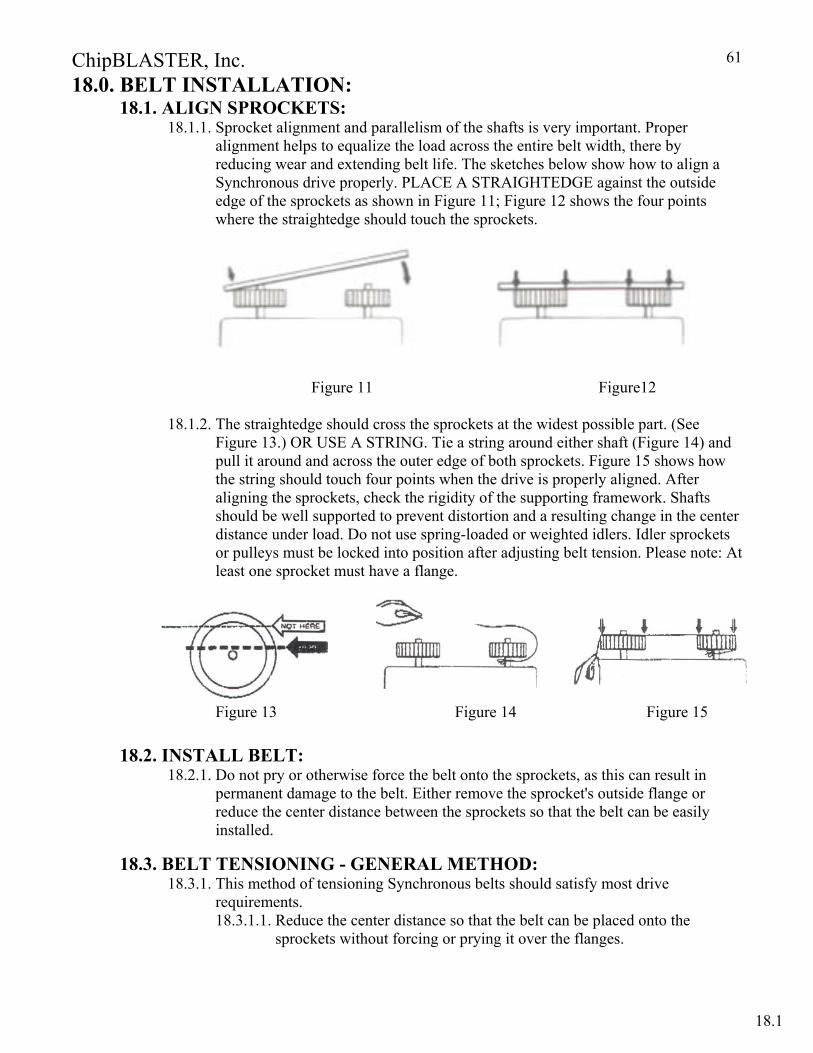
ChipBLASTER, Inc.
61
18.0. BELT INSTALLATION: 18.1. ALIGN SPROCKETS:
18.1.1. Sprocket alignment and parallelism of the shafts is very important. Proper alignment helps to equalize the load across the entire belt width, there by reducing wear and extending belt life. The sketches below show how to align a Synchronous drive properly. PLACE A STRAIGHTEDGE against the outside edge of the sprockets as shown in Figure 11; Figure 12 shows the four points where the straightedge should touch the sprockets.
Figure 11 Figure12
18.1.2. The straightedge should cross the sprockets at the widest possible part. (See
Figure 13.) OR USE A STRING. Tie a string around either shaft (Figure 14) and pull it around and across the outer edge of both sprockets. Figure 15 shows how the string should touch four points when the drive is properly aligned. After aligning the sprockets, check the rigidity of the supporting framework. Shafts should be well supported to prevent distortion and a resulting change in the center distance under load. Do not use spring-loaded or weighted idlers. Idler sprockets or pulleys must be locked into position after adjusting belt tension. Please note: At least one sprocket must have a flange.
Figure 13 Figure 14 Figure 15
18.2. INSTALL BELT: 18.2.1. Do not pry or otherwise force the belt onto the sprockets, as this can result in
permanent damage to the belt. Either remove the sprocket's outside flange or reduce the center distance between the sprockets so that the belt can be easily installed.
18.3. BELT TENSIONING - GENERAL METHOD: 18.3.1. This method of tensioning Synchronous belts should satisfy most drive
requirements. 18.3.1.1. Reduce the center distance so that the belt can be placed onto the
sprockets without forcing or prying it over the flanges.
18.1
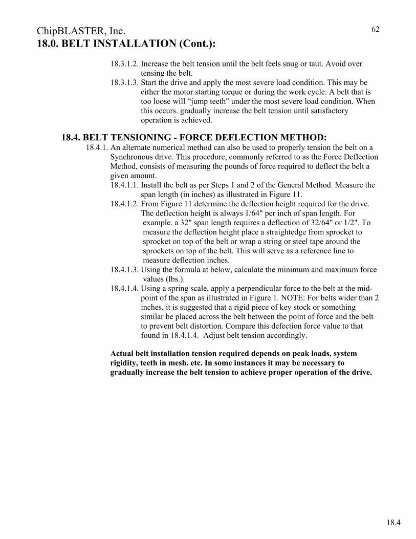
ChipBLASTER, Inc.
62
18.0. BELT INSTALLATION (Cont.):
18.3.1.2. Increase the belt tension until the belt feels snug or taut. Avoid over tensing the belt.
18.3.1.3. Start the drive and apply the most severe load condition. This may be either the motor starting torque or during the work cycle. A belt that is too loose will “jump teeth" under the most severe load condition. When this occurs. gradually increase the belt tension until satisfactory operation is achieved.
18.4. BELT TENSIONING - FORCE DEFLECTION METHOD: 18.4.1. An alternate numerical method can also be used to properly tension the belt on a
Synchronous drive. This procedure, commonly referred to as the Force Deflection Method, consists of measuring the pounds of force required to deflect the belt a given amount. 18.4.1.1. Install the belt as per Steps 1 and 2 of the General Method. Measure the
span length (in inches) as illustrated in Figure 11. 18.4.1.2. From Figure 11 determine the deflection height required for the drive.
The deflection height is always 1/64" per inch of span length. For example. a 32" span length requires a deflection of 32/64" or 1/2". To measure the deflection height place a straightedge from sprocket to sprocket on top of the belt or wrap a string or steel tape around the sprockets on top of the belt. This will serve as a reference line to measure deflection inches.
18.4.1.3. Using the formula at below, calculate the minimum and maximum force values (lbs.).
18.4.1.4. Using a spring scale, apply a perpendicular force to the belt at the mid- point of the span as illustrated in Figure 1. NOTE: For belts wider than 2 inches, it is suggested that a rigid piece of key stock or something similar be placed across the belt between the point of force and the belt to prevent belt distortion. Compare this defection force value to that found in 18.4.1.4. Adjust belt tension accordingly.
Actual belt installation tension required depends on peak loads, system rigidity, teeth in mesh. etc. In some instances it may be necessary to gradually increase the belt tension to achieve proper operation of the drive.
18.4
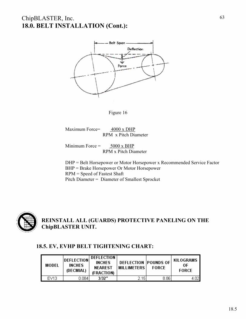
ChipBLASTER, Inc.
63
18.0. BELT INSTALLATION (Cont.):
Figure 16
Maximum Force= 4000 x DHP
RPM x Pitch Diameter Minimum Force = 5000 x BHP
RPM x Pitch Diameter
DHP = Belt Horsepower or Motor Horsepower x Recommended Service Factor BHP = Brake Horsepower Or Motor Horsepower RPM = Speed of Fastest Shaft Pitch Diameter = Diameter of Smallest Sprocket
REINSTALL ALL (GUARDS) PROTECTIVE PANELING ON THE ChipBLASTER UNIT.
18.5. EV, EVHP BELT TIGHTENING CHART:
18.5
ChipBLASTER, Inc.
64
19.0. SYSTEM CONTAMINATION PURGING PROCEDURE:
19.1. Tools Required: 19.1.1. 6mm Hex Head Wrench 19.1.2. 7/8” Wrench (For Unit Without Pressure Switch Option) 19.1.3. 1-1/4” Wrench (For Unit With Pressure Switch Option) 19.1.4. 5 Gallon Fluid Container 19.1.5. Section of Low Pressure Hose 19.1.6. Adapter Fitting ( ½” SAE to Hose Connection) 19.1.7. Small Phillips Screw Driver (For Unit With Pressure Switch Option)
19.2. Change Filter Bag: 19.2.1. Shut off all power to machine.
19.2.2. Open the Air Bleeder Valves located on the upper portion of the filter and on post filter to release any pressure on filter housing. 19.2.3 Visually check filter inlet and outlet pressure gauges for zero pressure.
IF THERE IS PRESSURE PRESENT DO NOT OPEN FILTER HOUSING
SEEK ASSISTANCE FROM QUALIFIED MAINTENANCE PERSONNEL TO RELIEVE PRESSURE.
19.2.4. Remove Filter Housing Lid. 19.2.5. Remove and inspect the “O-ring. 19.2.6. Remove Filter Displacement Device or Optional Hydrocyclonic Filter. 19.2.7. Remove and discard old filter.
DO NOT POUR REMAINING COOLANT FROM FILTER BAG BACK IN THE VESSEL OR CONTAMINATES WILL ENTER THE SYSTEM. 19.2.8 Replace with a new filter bag, making sure that it is seated firmly against
the top of the Filter Basket. 19.2.9 Replace Filter Displacement Device or Optional Hydrocyclonic Filter. 19.2.10 Fill filter housing with coolant. 19.2.11 Replace the “O-ring, making sure it is properly seated in the rim of the Filter Body. 19.2.10 Replace the lid, being careful not to displace “O-ring. 19.2.11 Torque all Filter Lid fasteners to 360-480 in-lbs.(40.6 – 54.2 Nm)
19.3 Remove access panel: 19.3.1. Remove rear access panel from ChipBLASTER unit (Panel opposite to the Gauge Panel).
19.4 For units without pressure switch: 19.4.1. Remove SAE pipe plug fitting from the high-pressure manifold. This
fitting is located on the lower right side of the high-pressure manifold. See Figure 8.
!
19.0 19.0

ChipBLASTER, Inc.
65
19.0. SYSTEM CONTAMINATION PURGING PROCEDURE (Cont.):
19.4. For units without pressure switch: Refer to Figure 17.
Figure 17 19.4.1. Install Hose Adapter Fitting and attach low-pressure hose.
ATTACH DISCHARGE TO FLUID CONTAINER TO ELIMINATE FLUID SPILLING.
19.5. For units with pressure switch: Refer to Figure 18.
Figure 18.
19.5.1. Remove electrical din connection from pressure switch. 19.5.2. Remove pressure switch. 19.5.3. Remove ½”x 1/8” reducing bushing. See Figure 18.
!
19.4
SOLENOID “A” P/N 4002
SOLENOID “B” P/N 4001
PLUG P/N 4156
FITTING NOT SHOWN FOR
CLARITY
REGULATOR (UNLOADER)
P/N 4546
SOLENOID “A” P/N 4002
SOLENOID “B” P/N 4001
PRESSURE SWITCH CORD
ASSEMBLY P/N
PRESSURE SWITCH P/N 9498
REDUCING BUSHING P/N 4620
FITTING NOT SHOWN FOR
CLARITY
REGULATOR (UNLOADER)
P/N 4546
ChipBLASTER, Inc.
66
19.0. SYSTEM CONTAMINATION PURGING PROCEDURE (Cont.):
19.5.4. Install hose adapter fitting and attach low-pressure hose.
NOTE: ATTACH DISCHARGE TUBE TO FLUID CONTAINER TO ELIMINATE FLUID SPILLING.
19.6. FLUSHING CYCLE
19.6.1. Press the AIR PURGE / RESET pushbutton located on the front of ChipBLASTER’s electrical enclosure.
19.6.2. Continue pressing the AIR PURGE /RESET pushbutton until 5 gallon container is full. 19.6.3. Close the Air Bleeder Valves located on the upper portion of the filter. 19.6.4. Press the AIR PURGE /RESET pushbutton again to continue flushing cycle. Fill
the 5-gallon container an addition (3) times to complete the flushing cycle.
19.7. REPLACE ALL PLUMBING FITTINGS AND PANELS TO THEIR ORIGINAL CONFIGURATION.
REPLACE ALL GUARDS BEFORE OPERATING ChipBLASTER
Any questions on the Contamination Purging Procedures, please contact the ChipBLASTER Service Department at (814) 724-6278. Have the model and serial number of your ChipBLASTER unit.
!
19.6
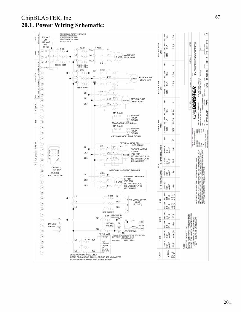
ChipBLASTER, Inc.
67
1.8
A
460
VAC
F
LA
POWER PLUG REFER TO DRAWINGT31-0006 OR T31-0006 T31-0006A OR T31-0006AT31-0006B OR T31-0006C AS REQUIRED.
230 VAC OR460 VAC 3 Ø 60 HZ
Chip
THIS
PR
INT
IS T
HE
PR
OPE
RTY
OF
Chi
pBLA
STE
R.
THIS
DO
CU
ME
NT
CO
NTA
INS
PR
OP
RIE
TAR
Y IN
FOR
MA
TIO
N A
ND
SU
CH
INFO
RM
ATI
ON
MAY
NO
T B
E D
ISC
LOSE
D T
O O
THE
RS
FOR
AN
YP
UR
PO
SE
OR
US
ED
FO
R M
AN
UFA
CTU
RIN
G P
UR
PO
SES
WIT
HO
UT
WR
ITTE
N P
ER
MIS
SIO
N F
RO
M C
hipB
LAS
TER
.
Tole
ranc
es
0.00
05
0.01
0.00
5
1/32
BR
EAK
ALL
SH
ARP
ED
GE
S
(NO
NA
CC
UM
ULA
TIVE
)
X.X
X
RE
MO
VE
ALL
BU
RR
S &
X.X
BLA
STER
X.X
XXX
X.X
XX
Chip
UN
IT:
SIZ
E: C
QTY
.
CU
STO
MER
:
AP
PR
OV
ED B
Y:
FAX:
(814
)724
-628
7P
HO
NE
: (81
4)72
4-62
78
BLASTER
ww
w.c
hipb
last
er.c
omD
RA
WN
BY
:D
ATE
:
TITL
E:
IT.
DR
AW
ING
NU
MBE
R:
OF
SH
EET
:R
EV:
MA
T'L:
PA
RT
No.
REV
DES
CR
IPTI
ON
DA
TE
SC
ALE
:
NO
TES
DE
SC
RIP
TIO
N
1360
5 S
. MO
SIE
RTO
WN
RO
AD
ME
AD
VIL
LE, P
A 1
6335
US
A
NA
ME
EV
13, E
VH
P
EV
PO
WE
R W
IRN
G S
CH
EM
ATI
C
WP
A15
AU
G 0
7TI
31E
V-1
STD
17
CN
TS
RETURN PUMP SEE CHART
RETURN PUMPSIGNAL
OPTIONAL MAGNETIC SKIMMER
MAGNETIC SKIMMER0.17 HP1725 RPM230 VAC 3Ø FLA 1.2460 VAC 3Ø FLA 0.642CZ FRAME
OPTIONAL MORI PUMP SIGNAL
RETURN PUMPSIGNAL
COOLER MOTOR0.25 HP1700 RPM230 VAC 3Ø FLA 1.0460 VAC 3Ø FLA 0.5IEC 63 FRAME
OPTIONAL COOLERSEE BELOW
UNIT
100
(IF USED)
PRIMARY TRANSFORMER TAP CONNECTION230V INPUT CONNECT H1,H3 CONNECT H2,H4460V INPUT CONNECT H2,H3
TO MISTBLASTER
137
136
134
135
133
131
132
130
129
127
128
126
4L1
4L3
20A 230VAC PN #7590 ONLYNOTE: FOR A DROP IN CHILLER FOR 460 VAC A STEP DOWN TRANSFORMER WILL BE REQUIRED.
H3
460 VACWIRING
1L3
1L1 24 CB
H4
1L3
H2
H1
1L2
1L1
X1H34 CB
SEE CHART
1L3500 VA 6 AMPS
1000 VA 10 AMPS1 TXH4
500VA USE (2)1000VA USE (3)
SEE CHART
1L1
230 VACWIRING
3 CB
9 CB
9L3
X2H1
H2COM
3
9L2
9L1
2
1
COOLER RECTEPTACLE
4
125
124
123
122
120
121
11956
117
118
116
115
113
114
112
UPD
ATED
460
V 1,
2 &
9C
B's
& 4
CB
B
110
111
109
108
106
107
105
2
GND103
104
L2
L3102
101
3
WP
A04
SE
P 0
7
L1100 1
MR 3 AUX
1
KEYING PIN TYP.
23
2L2
2L3
2L1
2L3
2L2
2L1
4T3
4T2
MR 5
5T2
5T3
5T1
4T3
4T2
5 MTR
4 MTR
3
2
14
22
4T1
MR 3 AUXSTANDARD PUMP SIGNAL
MR 44T1
6
1
1TB
21
13
5
1TB
5
6
2L1
2L3
2L2
2L1
2L3
2L2
SEE CHART
1L3
1L2
2
SEE CHART
3
1 CB1
1AL2
2CB1L1
1AL3
1AL1
3T1
3T2
3T3
3T1
3T3
3T2
MR 3
2T3
2T2
1
3 MTR
3
2
FILTER PUMP SEE CHART2 MTR
1T2T2L2
MR 2
L3 T3GND
2T1
1T3
1 AFDL1 T1 1T1
MAIN PUMPSEE CHART1 MTR
1 H
P M
ISTB
LAST
ER
230
VAC
3
Ø60
HZ
230
VAC
3
Ø60
HZ
200
63 A
230
VAC
3
Ø60
HZ
MO
DEL
CH
AR
T
EV
13E
VH
P
460
VA
C
3 Ø
60 H
Z
1 C
B 40 A
(1)
200
8 A
(3)
5 A
(2)
230
VAC
3
Ø60
HZ
460
VAC
3
Ø60
HZ
2 C
B 15 A
16 A
460
VA
C
3 Ø
60 H
Z
3 C
B 4 A
(3)
2 A
(2)
NO
TE:
(1) S
ET
IR C
OM
P TO
0.8
(2) U
SE F
OR
500
VA
TRAN
SFO
RM
ER(3
) USE
FO
R 1
000
VA T
RA
NS
FOR
ME
R
[U
SE
100
0 VA
TR
AN
SFO
RM
ER
W
ITH
6 O
UTL
ET
UN
ITS
ON
LY]
12.8
A
460
VAC
F
LA
15 A
3 H
P M
ISTB
LAST
ER
460
VA
C
3 Ø
60 H
Z
9CB
460
VAC
3
Ø60
HZ
16 A
15 A
230
VAC
3
Ø60
HZ
20 A
MAI
N P
UM
P
215T
FRA
ME
SIZ
EH
P
10
230
VAC
FL
A
1MTR
25.5
A1.
8 A
460
VAC
F
LA
FILT
ER
PU
MP
FRA
ME
SIZ
EH
P
1
230
VA
C
FLA
2MTR
3.1
A
RE
TUR
N P
UM
P
FRA
ME
SIZ
EH
P
1
230
VAC
FL
A
3MTR
3.1
A
L1
GND
L2
OPTIONALCHILLERUNIT230 V 1Ø8000 BTU
4
3
2
1
1L3
1L1
1L2
1ACB
230V - 40 A460V - 20 A
115 VAC
3CB
(500
VA)
WA
S 4A
CR
B4
DEC
07
20.1. Power Wiring Schematic:
20.1
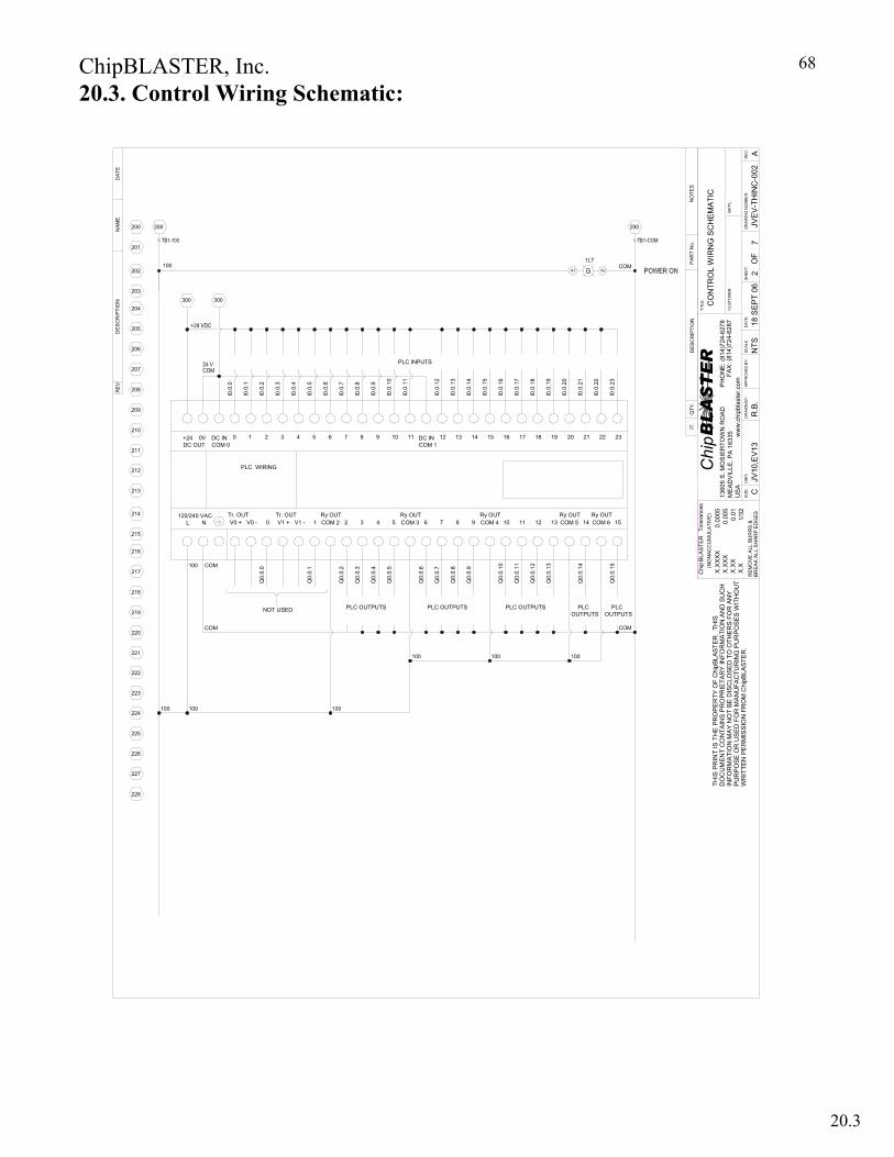
ChipBLASTER, Inc.
68
PLC INPUTS
I0.0
.11
COM 3Ry OUT
Q0.
0.5
Q0.
0.4
Q0.
0.3
Q0.
0.2
Q0.
0.1
Q0.
0.0
223
224
225
100 100
220
221
222
218
219
COM
100
NOT USED PLC OUTPUTS
PLC WIRING
V0 -120/240 VAC214
215
217
216
212
213
Tr. OUT
COM100
NL V0 +
DC OUT+24
209
210
211
206
207
208
DC INCOM 0
0V 10
I0.0
.0
I0.0
.1
Ry OUTCOM 2
Tr. OUTV1 +0 1V1 - 32 54
632 4 5
I0.0
.4
I0.0
.3
I0.0
.2
I0.0
.6
I0.0
.5
87 109
I0.0
.8
I0.0
.7
I0.0
.10
I0.0
.9
Q0.
0.15
Q0.
0.14
Q0.
0.13
Q0.
0.12
Q0.
0.11
Q0.
0.10
Q0.
0.9
Q0.
0.8
Q0.
0.7
Q0.
0.6
100
PLC OUTPUTS
100
PLC OUTPUTS
COM
PLCOUTPUTS
100
PLCOUTPUTS
I0.0
.19
76 8 9Ry OUT
10COM 4 1211
1412DC INCOM 1
11 13I0
.0.1
2
I0.0
.14
I0.0
.13
1615 1817
I0.0
.17
I0.0
.16
I0.0
.15
I0.0
.18
Ry OUTRy OUT14COM 513 15COM 6
212019 2322
I0.0
.21
I0.0
.20
I0.0
.23
I0.0
.22
300203
204
205
200
201
202100
200
300
COM1LT
A1 A2
200
226
228
227
Chip
THIS
PR
INT
IS T
HE
PR
OP
ER
TY O
F C
hipB
LAST
ER
. TH
ISD
OC
UM
EN
T C
ON
TAIN
S P
RO
PRIE
TAR
Y IN
FOR
MA
TIO
N A
ND
SU
CH
INFO
RM
ATI
ON
MA
Y N
OT
BE
DIS
CLO
SED
TO
OTH
ERS
FO
R A
NY
PU
RP
OS
E O
R U
SED
FO
R M
ANU
FAC
TUR
ING
PU
RPO
SES
WIT
HO
UT
WR
ITTE
N P
ER
MIS
SIO
N F
RO
M C
hipB
LAS
TER
.
Tole
ranc
es
0.00
05
0.01
0.00
5
1/32
BR
EAK
ALL
SH
ARP
ED
GES
(NO
NAC
CU
MU
LATI
VE)
X.X
X
RE
MO
VE A
LL B
UR
RS
&
X.X
BLA
STER
X.X
XXX
X.X
XX
Chip
UN
IT:
SIZ
E: C
QTY
.
CU
STO
ME
R:
AP
PR
OVE
D B
Y:
FAX
: (81
4)72
4-62
87P
HO
NE
: (81
4)72
4-62
78
BLASTER
ww
w.c
hipb
last
er.c
omD
RA
WN
BY
:D
ATE
:
TITL
E:
IT.
DR
AW
ING
NU
MB
ER
:
OF
SH
EE
T:R
EV
:
MA
T'L:
PA
RT
No.
REV
DE
SCR
IPTI
ON
DA
TE
SC
ALE
:
NO
TES
DES
CR
IPTI
ON
1360
5 S
. MO
SIE
RTO
WN
RO
AD
ME
AD
VIL
LE, P
A 1
6335
US
A
NA
ME
JV10
,EV
13
CO
NTR
OL
WIR
NG
SC
HE
MA
TIC
R.B
.18
SE
PT 0
6JV
EV-
THIN
C-0
022
7A
NTS
20.3. Control Wiring Schematic:
20.3
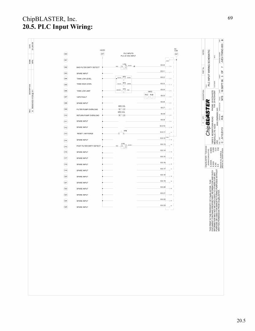
ChipBLASTER, Inc.
69
SPARE INPUT
SPARE INPUT
SPARE INPUT
SPARE INPUT
SPARE INPUT
SPARE INPUT
SPARE INPUT
SPARE INPUT
1AFD FAULT
POST FILTER DIRTY DETECT
RETURN PUMP OVERLOAD
FILTER PUMP OVERLOAD
TANK LOW LIMIT
TANK HIGH LEVEL
TANK LOW LEVEL
SPARE INPUT
I0.0.8
3 PSCOMRED
BLACKNO
NC
I0.0.22
I0.0.23 23
22
I0.0.15
I0.0.21
I0.0.19
I0.0.20
I0.0.17
I0.0.18
I0.0.16
I0.0.14
I0.0.12
I0.0.13
I0.0.10
I0.0.11
I0.0.9
20
21
19
17
18
16
15
14
12
13
10
11
9
8
207
MR3 3OL
MR2 2OL
2FS
1FS
3FS
96
96
BROWN
BLACK
BLACK
95
95
WHITE
GREEN
RED
PLC 24 VDC INPUTPLC INPUTS
I0.0.1
I0.0.7
I0.0.5
I0.0.6
I0.0.3
I0.0.4
I0.0.2
I0.0.0
6
7
5
.3
4
1
2
0
207
1 PSCOMRED
BLACKNC
NOØBAG FILTER DIRTY DETECT
SPARE INPUT
SPARE INPUT
SPARE INPUT
SPARE INPUT
314
320
323
325
324
322
321
317
319
318
316
315
311
313
312
310
309
308
307
306
305
304
303
302
301
300
COM 0
COM 1
Chip
THIS
PR
INT
IS T
HE
PR
OP
ER
TY O
F C
hipB
LAS
TER
. TH
ISD
OC
UM
EN
T C
ON
TAIN
S P
RO
PR
IETA
RY
INFO
RM
ATI
ON
AN
D S
UC
HIN
FOR
MA
TIO
N M
AY
NO
T B
E D
ISC
LOS
ED
TO
OTH
ERS
FO
R A
NY
PU
RP
OSE
OR
US
ED
FO
R M
AN
UFA
CTU
RIN
G P
UR
POS
ES
WIT
HO
UT
WR
ITTE
N P
ER
MIS
SIO
N F
RO
M C
hipB
LAST
ER
.
Tole
ranc
es
0.00
05
0.01
0.00
5
1/32
BR
EA
K A
LL S
HA
RP
ED
GE
S
(NO
NA
CC
UM
ULA
TIV
E)
X.X
X
REM
OV
E A
LL B
UR
RS
&
X.X
BLA
STE
R
X.X
XXX
X.X
XX
Chip
UN
IT:
SIZ
E: C
QTY
.
CU
STO
MER
:
APP
RO
VED
BY:
FAX:
(814
)724
-628
7P
HO
NE
: (81
4)72
4-62
78
BLASTER
ww
w.c
hipb
last
er.c
omD
RA
WN
BY:
DAT
E:
TITL
E:
IT.
DR
AW
ING
NU
MBE
R:
OF
SH
EET
:R
EV:
MA
T'L:
PA
RT
No.
RE
VD
ES
CR
IPTI
ON
DA
TE
SCAL
E:
NO
TES
DE
SC
RIP
TIO
N
1360
5 S
. MO
SIE
RTO
WN
RO
AD
M
EA
DV
ILLE
, PA
163
35U
SA
NA
ME
JV10
,EV1
3
PLC
INP
UT
WIR
ING
SC
HE
MA
TIC
R.B
.18
SE
PT
06JV
EV-
THIN
C-0
033
7B
NTS
SPARE INPUT
R1BR1C
1AFD
3
1PB4RESET / AIR PURGE
SPARE INPUT
B R
EMO
VED
41C
B @
311
WPA
25 J
AN 0
8
20.5. PLC Input Wiring:
20.5
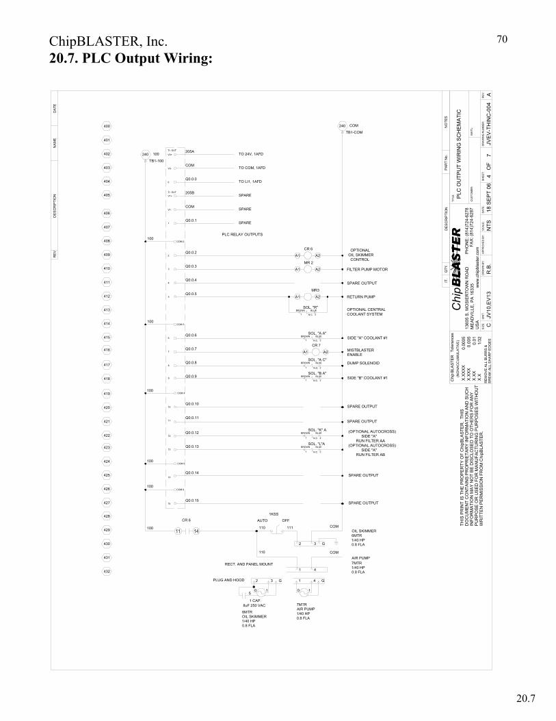
ChipBLASTER, Inc.
70
SOL. "A C"Q0.0.8
430
432
431
428
427
429
424
425
426
421
422
423
419
420
418
415
416
417
COM 5
COM 6
15
14
13
Q0.0.15
Q0.0.14
Q0.0.13
COM 4
10
12
11
8
9
Q0.0.10
Q0.0.12
Q0.0.11
Q0.0.9
MR3
A1 A2
BROWN BLUE
N.O. 21
412
414
413
409
410
411
406
100
407
408
404
405
Q0.0.4
COM 3
7
6
5
4
Q0.0.6
Q0.0.7
Q0.0.5
COM 2
2
3
V1-
1
Q0.0.2
Q0.0.3
Q0.0.1
TB1-100
401
402
403
400
240 100
V0-
0
V1+
V0+
Q0.0.0
BROWN BLUESOL. "A A"
2N.C.1
A1
MR 2
A2 FILTER PUMP MOTOR
TB1-COM
COM240
SPARE OUTPUT
PLC RELAY OUTPUTS
SPARE OUTPUT
SPARE OUTPUT
BROWNSOL. "K" A
BLUE
N.C.1 2
(OPTIONAL AUTOCROSS) SIDE "A" RUN FILTER AA
BROWNSOL. "L"A
21 N.C.
BLUE (OPTIONAL AUTOCROSS) SIDE "A" RUN FILTER AB
A1
CR 6
A2 OPTIONAL OIL SKIMMER CONTROL
RETURN PUMP
DUMP SOLENOID
SIDE "A" COOLANT #1
SOL. "B A"BLUE
1 N.C. 2
BROWN SIDE "B" COOLANT #1
SPARE OUTPUT
COM
COM
PLUG AND HOOD
RECT. AND PANEL MOUNT
CR 6
6MTROIL SKIMMER1/40 HP 0.8 FLA
1 CAP.8uF 250 VAC
2
50
G
1
3
7MTRAIR PUMP1/40 HP 0.8 FLA
0
1 4
1
G
OFF
110
AUTO
1KSS
1
2 G
4
3
7MTR1/40 HP 0.8 FLA
6MTR1/40 HP 0.8 FLA
AIR PUMP
OIL SKIMMER110 111
Chip
THIS
PR
INT
IS T
HE
PR
OPE
RTY
OF
Chi
pBLA
STE
R.
THIS
DO
CU
MEN
T C
ON
TAIN
S P
RO
PR
IETA
RY
INFO
RM
ATI
ON
AN
D S
UC
HIN
FOR
MA
TIO
N M
AY
NO
T B
E D
ISC
LOS
ED
TO
OTH
ER
S FO
R A
NY
PU
RP
OS
E O
R U
SE
D F
OR
MAN
UFA
CTU
RIN
G P
UR
PO
SE
S W
ITH
OU
TW
RIT
TEN
PE
RM
ISS
ION
FR
OM
Chi
pBLA
STE
R.
Tole
ranc
es
0.00
05
0.01
0.00
5
1/32
BRE
AK A
LL S
HA
RP
ED
GES
(NO
NA
CC
UM
ULA
TIVE
)
X.X
X
REM
OV
E AL
L BU
RR
S &
X.X
BLA
STE
R
X.X
XX
XX
.XX
X
Chip
UN
IT:
SIZ
E: C
QTY
.
CU
STO
MER
:
AP
PRO
VE
D B
Y:
FAX:
(814
)724
-628
7P
HO
NE:
(814
)724
-627
8
BLASTER
ww
w.c
hipb
last
er.c
omD
RAW
N B
Y:D
ATE:
TITL
E:
IT.
DR
AW
ING
NU
MBE
R:
OF
SH
EET:
RE
V:
MAT
'L:
PA
RT
No.
REV
DES
CR
IPTI
ON
DAT
E
SC
ALE
:
NO
TES
DES
CR
IPTI
ON
1360
5 S
. MO
SIE
RTO
WN
RO
AD
M
EA
DV
ILLE
, PA
163
35U
SA
NAM
E
JV10
,EV1
3
PLC
OU
TPU
T W
IRIN
G S
CH
EM
ATI
C
R.B
.18
SEP
T 06
JVE
V-T
HIN
C-0
044
7A
NTS
Tr. OUT
Tr. OUT
TO COM, 1AFD
TO 24V, 1AFD
TO LI1, 1AFD
SPARE
COM
205A
205B
COM
MISTBLASTERENABLE
SPARE OUTPUT
A1
CR 7
A2
SPARE
SPARE
100
100
100
100
100
N.C.
SOL. "R"BROWN
1 2
BLUE OPTIONAL CENTRALCOOLANT SYSTEM
20.7. PLC Output Wiring:
20.6 20.7
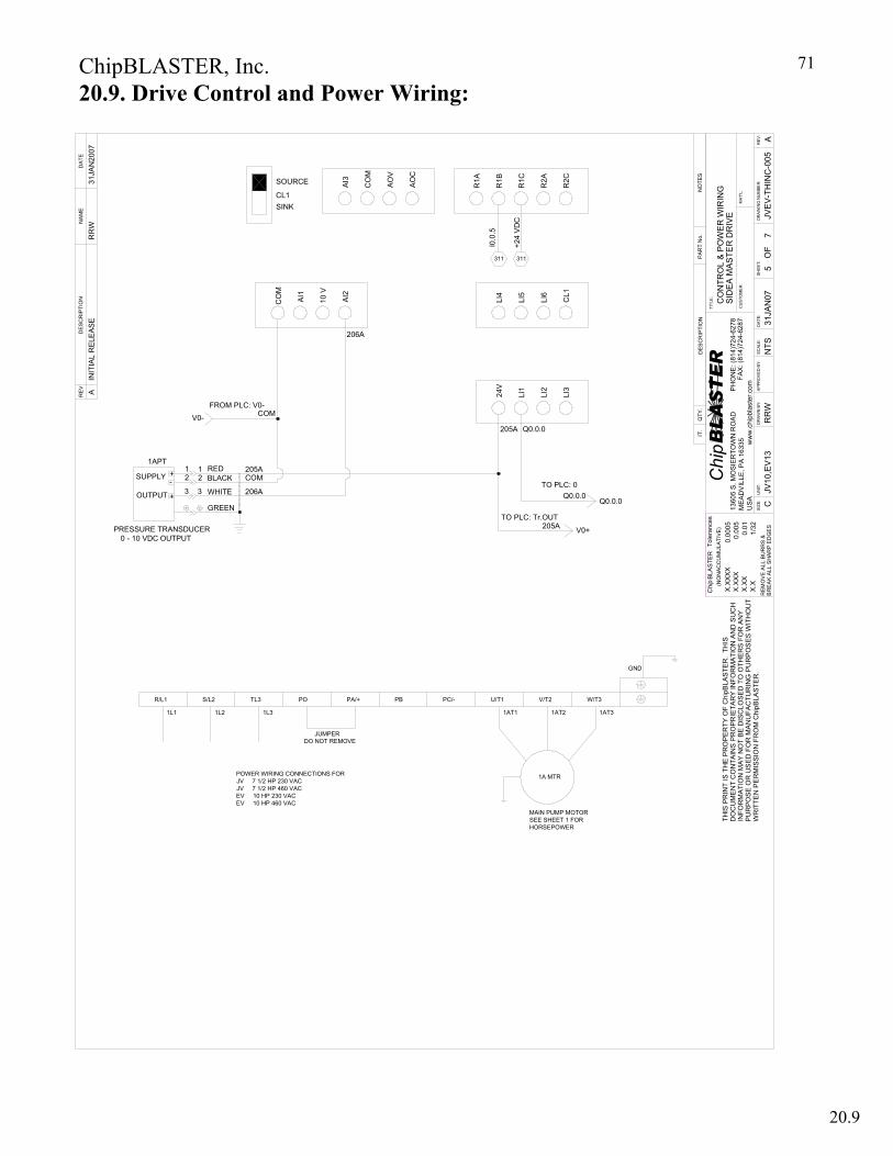
ChipBLASTER, Inc.
71
Chip
THIS
PR
INT
IS T
HE
PR
OP
ER
TY O
F C
hipB
LAS
TER
. TH
ISD
OC
UM
EN
T C
ON
TAIN
S P
RO
PR
IETA
RY
INFO
RM
ATIO
N A
ND
SU
CH
INFO
RM
ATI
ON
MAY
NO
T BE
DIS
CLO
SED
TO
OTH
ER
S FO
R A
NY
PUR
POS
E O
R U
SED
FO
R M
AN
UFA
CTU
RIN
G P
UR
PO
SES
WIT
HO
UT
WR
ITTE
N P
ERM
ISSI
ON
FR
OM
Chi
pBLA
STE
R.
Tole
ranc
es
0.00
05
0.01
0.00
5
1/32
BR
EA
K A
LL S
HA
RP
ED
GES
(NO
NA
CC
UM
ULA
TIVE
)
X.XX
REM
OV
E A
LL B
UR
RS
&
X.X
BLA
STE
R
X.XX
XXX.
XXX
Chip
UN
IT:
SIZ
E: C
QTY
.
CU
STO
ME
R:
APP
RO
VE
D B
Y:
FAX
: (81
4)72
4-62
87PH
ON
E: (
814)
724-
6278
BLASTER
ww
w.c
hipb
last
er.c
omD
RA
WN
BY:
DAT
E:
TITL
E:
IT.
DR
AW
ING
NU
MBE
R:
OF
SH
EET:
RE
V:
MAT
'L:
PAR
T N
o.
RE
VD
ES
CR
IPTI
ON
DAT
E
SC
ALE:
NO
TES
DES
CR
IPTI
ON
1360
5 S.
MO
SIER
TOW
N R
OAD
M
EAD
VIL
LE, P
A 16
335
USA
NAM
E
JV10
,EV
13
SID
EA
MA
STE
R D
RIV
EC
ON
TRO
L &
PO
WE
R W
IRIN
G
RR
W31
JAN
07JV
EV-
THIN
C-0
055
7A
NTS
PRESSURE TRANSDUCER 0 - 10 VDC OUTPUT
PO
JUMPERDO NOT REMOVE
POWER WIRING CONNECTIONS FORJV 7 1/2 HP 230 VACJV 7 1/2 HP 460 VACEV 10 HP 230 VACEV 10 HP 460 VAC
1L21L1
R/L1 S/L2 TL3
1L3
PA/+ PB PC/-
MAIN PUMP MOTORSEE SHEET 1 FOR HORSEPOWER
1A MTR
1AT1
U/T1 V/T2
1AT2 1AT3
W/T3
GND
R1AAO
C
AO
V
AI3
CO
M
SOURCE
REDBLACK
GREEN
WHITE
SUPPLY +-
+OUTPUT
1APT1 1
2
3
2
3
COM205A
206A
AI1
CO
M
SINKCL1
AI2
10 V
206A
R2C
R1B
R1C
R2A
LI3
Q0.0.0205A
LI1
24V
LI2
CL1
LI5
LI4
LI6
INIT
IAL
REL
EAS
EA
RR
W31
JAN
2007
TO PLC: Tr.OUT
V0+
FROM PLC: V0-COMV0-
TO PLC: 0
205A
Q0.0.0Q0.0.0
+24
VD
C
311
I0.0
.5
311
20.9. Drive Control and Power Wiring:
20.9

ChipBLASTER, Inc.
72
Chip
THIS
PR
INT
IS T
HE
PR
OP
ER
TY O
F C
hipB
LAST
ER
. TH
ISD
OC
UM
ENT
CO
NTA
INS
PR
OPR
IETA
RY
INFO
RM
ATI
ON
AN
D S
UC
HIN
FOR
MA
TIO
N M
AY N
OT
BE
DIS
CLO
SED
TO
OTH
ER
S FO
R A
NY
PU
RPO
SE O
R U
SE
D F
OR
MAN
UFA
CTU
RIN
G P
UR
PO
SES
WIT
HO
UT
WR
ITTE
N P
ERM
ISS
ION
FR
OM
Chi
pBLA
STER
.
Tole
ranc
es
0.00
05
0.01
0.00
5
1/32
BR
EAK
ALL
SH
AR
P E
DG
ES
(NO
NA
CC
UM
ULA
TIV
E)
X.X
X
RE
MO
VE
ALL
BU
RR
S &
X.X
BLA
STE
R
X.X
XXX
X.X
XX
Chip
UN
IT:
SIZ
E: D
QTY
.
CU
STO
MER
:
APP
RO
VED
BY:
FAX
: (81
4)72
4-62
87P
HO
NE
: (81
4)72
4-62
78
BLASTER
ww
w.c
hipb
last
er.c
omD
RA
WN
BY:
DAT
E:
TITL
E:
IT.
DR
AW
ING
NU
MBE
R:
OF
SHEE
T:R
EV:
MAT
'L:
PA
RT
No.
REV
DE
SC
RIP
TIO
ND
ATE
SCAL
E:
NO
TES
DE
SC
RIP
TIO
N
1360
5 S.
MO
SIER
TOW
N R
OAD
M
EA
DV
ILLE
, PA
163
35U
SA
NA
ME
JV10
,EV1
3
PO
WER
PLU
G W
IRIN
G D
IAG
RAM
PO
WER
AN
D M
ISTB
LAST
ER
RR
W31
JAN
2007
JVEV
-TH
INC
-006
67
AN
TS
L33
3 PHASE SUPPLY INPUT REFER TOPOWER WIRING FOR CURRENT DRAW. GND
ChipBLASTER
POWER INTERFACE P/N 9484 PLUG (12 PIN)
MACHINING CENTER1CB
1 L1
L22
COMMONCOM6COM
9L3
9L2
STD. 1 HP MTR OPT. 3 HP MTR. 240 V 16 A 240 V 20 A 480 V 16 A 480 V 16 A
VFD L1
L3
L2
GND
1
3
2
9L19 CB
OPTIONALChipBLASTER TO MISTBLASTER INTERFACE PLUG (6 PIN)
CHIPBLASTER
TERMINAL BLOCK
115VAC SUPPLY100
MISTBLASTER
TERMINAL BLOCK
101
INTERFACE PLUG
45
100101
START SIGNALCR7
INIT
IAL
RE
LEAS
EA
21 24
RR
W31
JAN
2007
CONTROL INTERFACE ETHERNET CABLE (5171 CABLE 1 METER)
20.13. Power and Mistblaster Interface:
20.10 20.13 20.13
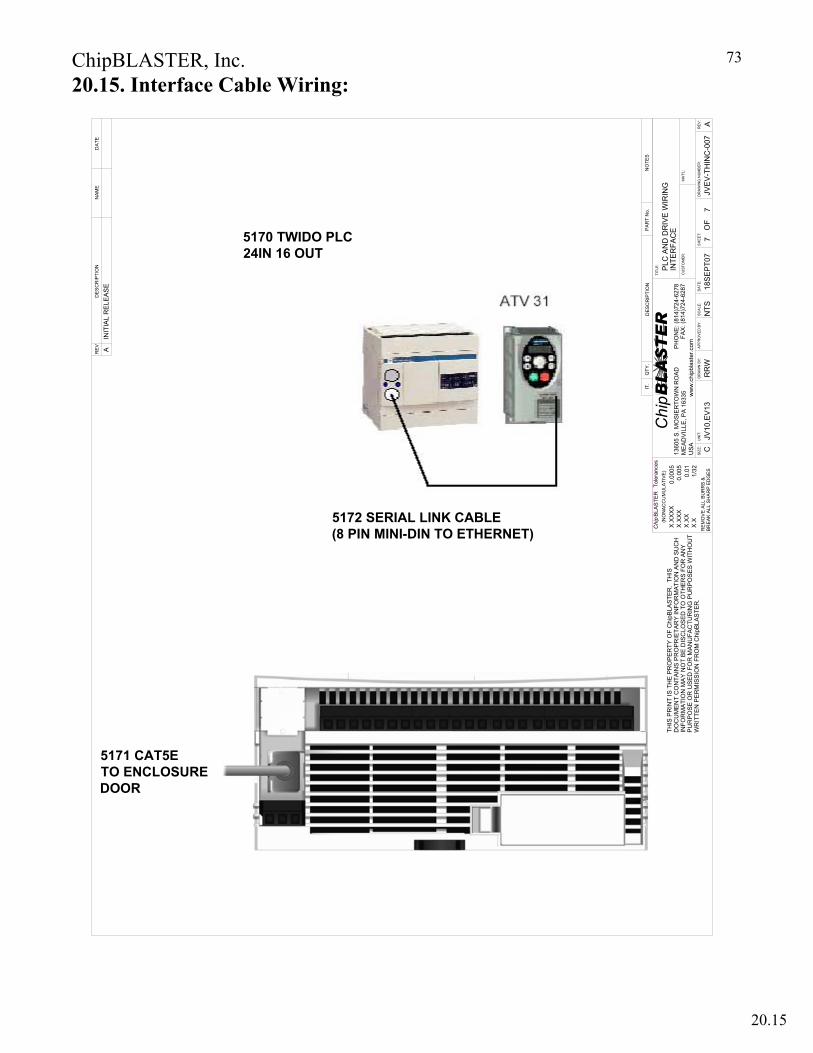
ChipBLASTER, Inc.
73
Chip
THIS
PR
INT
IS T
HE
PR
OP
ER
TY O
F C
hipB
LAST
ER.
THIS
DO
CU
ME
NT
CO
NTA
INS
PR
OP
RIE
TAR
Y IN
FOR
MAT
ION
AN
D S
UC
HIN
FOR
MA
TIO
N M
AY
NO
T B
E D
ISC
LOSE
D T
O O
THE
RS
FOR
AN
YP
UR
PO
SE
OR
US
ED
FO
R M
AN
UFA
CTU
RIN
G P
UR
POSE
S W
ITH
OU
TW
RIT
TEN
PE
RM
ISS
ION
FR
OM
Chi
pBLA
STE
R.
Tole
ranc
es
0.00
05
0.01
0.00
5
1/32
BRE
AK A
LL S
HA
RP
EDG
ES
(NO
NAC
CU
MU
LATI
VE)
X.X
X
RE
MO
VE
ALL
BU
RR
S &
X.X
BLA
STE
R
X.X
XXX
X.X
XX
Chip
UN
IT:
SIZ
E: C
QTY
.
CU
STO
MER
:
APP
RO
VED
BY
:
FAX
: (81
4)72
4-62
87P
HO
NE
: (81
4)72
4-62
78
BLASTER
ww
w.c
hipb
last
er.c
omD
RA
WN
BY:
DAT
E:
TITL
E:
IT.
DR
AW
ING
NU
MBE
R:
OF
SH
EET
:R
EV:
MA
T'L:
PAR
T N
o.
REV
DES
CR
IPTI
ON
DAT
E
SC
ALE
:
NO
TES
DES
CR
IPTI
ON
1360
5 S
. MO
SIE
RTO
WN
RO
AD
M
EA
DV
ILLE
, PA
163
35U
SA
NA
ME
JV10
,EV1
3
INTE
RFA
CE
PLC
AN
D D
RIV
E W
IRIN
G
RR
W18
SE
PT07
JVE
V-T
HIN
C-0
077
7A
NTS
INIT
IAL
RE
LEAS
EA
5170 TWIDO PLC24IN 16 OUT
5172 SERIAL LINK CABLE(8 PIN MINI-DIN TO ETHERNET)
5171 CAT5ETO ENCLOSUREDOOR
20.15. Interface Cable Wiring:
20.15
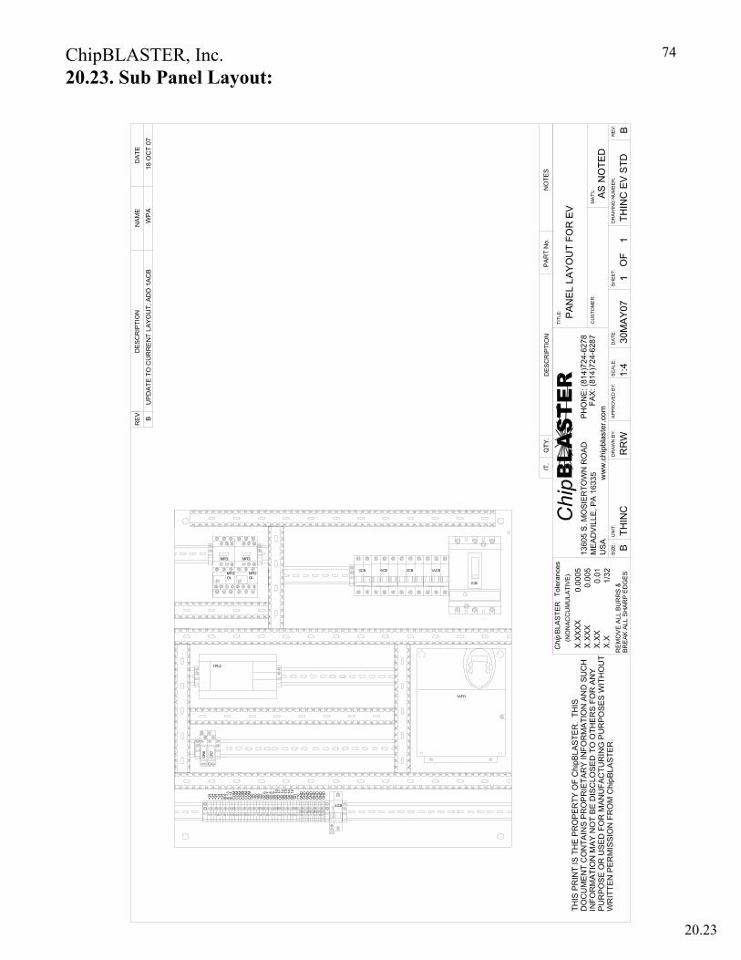
ChipBLASTER, Inc.
74
THIN
C
PAN
EL L
AYO
UT
FOR
EV
RR
W30
MA
Y07
THIN
C E
V ST
D1
1
AS
NO
TED
B1:
4
MR3OL
MR3
MR2OL
MR2
1ACB
WP
A18
OC
T 07
1PLC
CR
7
CR
6
101
+24
+24
100
100
CO
M
I0.1
3I0
.14
CO
MC
OM
CO
MC
OM
+24
+24
+24
I0.0
CO
M
Q0.
9Q
0.10
Q0.
11Q
0.12
Q0.
13Q
0.14
100
100
Q0.
6Q
0.7
Q0.
8
Q0.
15
4CB
GN
DG
ND
110
GN
DG
ND
GN
DG
ND
GN
DG
ND
9CB
1AFD
UP
DA
TE T
O C
UR
RE
NT
LAY
OU
T, A
DD
1AC
B
2CB
1CB
B
3CB
20.23. Sub Panel Layout:
20.16 20.17 20.20 20.23

ChipBLASTER, Inc.
75
EV
13, E
VHP
SIN
GLE
FIL
TER
EV
13, E
VH
P P
IPIN
G S
CH
EMA
TIC
R.B
.22
SE
PT
06T3
1EV
-1 S
F1
1B
NTS
WAS
H D
OW
N
HO
SE
OP
TIO
NA
LC
OO
LER
(Q0.
0.1)
HIG
H P
RE
SSU
RE
G
AU
GE
1/4"
BLU
EQ
1.3
WA
SH
DO
WN
S
OL
AA
FILT
ER
INLE
T
GA
UG
E
1"
INLE
T FI
LTE
R S
OC
K
300
MIC
RO
N
1/4"
RE
D
PO
STFI
LTE
R
DIR
TY
BA
GFI
LTER
D
IRTY
1"
I0.0
.12
3PS
I0.0
.12P
S
5 M
ICR
ON
FIL
TER
FILT
ER
PU
MP
1"1"
149
MIC
RO
N
FILT
ER
N.O
.Q
0.0.
12M
TR
1"
M B
AG
FILT
ER
PO
STFI
LTER
1"
Q1.
3W
AS
H
DO
WN
SO
L B
B
N.C
.
OPT
ION
AL
DR
OP
IN
CH
ILLE
R MA
NIF
OLD
BLO
CK
HIG
H P
RE
SS
UR
E U
NIT
RE
SE
RV
OIR
LOW
LE
VE
L I0
.0.2
HIG
H L
EV
EL
I0.0
.3
1/4"
CLE
AR
1-1/
2"
1/4"
CLE
AR
1/4"
BLA
CK
1/2"
L OW
LIM
IT I0
.0. 4
RE
SER
VO
IR
DR
AIN
FILT
ER
OU
TLE
T
G
AU
GE
OV
ER
FLO
W
Q0.
0.5
CO
OLA
NT
1
SO
L A
Q0.
0.7
DU
MP
SO
L C
Q
0.0.
6C
OO
LAN
T 2
S
OL
B
BLO
WO
FF
RE
GU
LATE
RQ
0.0.
81M
TR
HIG
H P
RE
SSU
RE
P
UM
P
M
3/4"
1/4" P
ULS
ATI
ON
DA
MP
ER
(AC
CU
MU
LATO
R)
1/4"
CLE
AR
1/4"
CLE
AR
1/4"
BLA
CK
1PT
PR
ES
SU
RE
TRA
NS
DU
CE
R
PT
N.O
.N
.C.
N.C
.
1PT
PR
ES
SUR
ETR
AN
SDU
CE
R
PU
LSA
TIO
N D
AM
PEN
ER
(A
CC
UM
ULA
TOR
)
DU
MP
SO
L. S
OL.
"C"
OP
TIO
NAL
CO
OLA
NT
# 3
OU
TLE
T
Q
0.Q
1.2
CO
OLA
NT
3
SO
L D
CO
OLA
NT
#1 S
OL.
"A"
N.C
.
MA
CH
INE
TO
OL
SUM
P
M
RET
UR
N (T
RA
NS
FER
) PU
MP
(OP
TIO
NAL
)
Q0.
0.9
3M
TR
1"
CO
OLA
NT
No.
3 (
OPT
ION
AL
EV 1
3)
CO
OLA
NT
No.
1
TOO
LIN
G O
RFI
CE
OV
ER
FLO
W F
RO
M C
HIP
BLA
STE
R
CO
OLA
NT
No.
2
MA
CH
INE
TO
OL
1/2"
1/2"
1/2"
1-1/
2"
NO
TES
:1.
TH
IS D
RA
WIN
G IS
A S
CH
EM
ATI
C O
NLY
OF
P
IPIN
G A
ND
DO
ES
NO
T R
EP
RE
SEN
T AN
AC
TUAL
N
UM
BE
R O
F FI
TTIN
GS
RE
QU
IRED
TO
PLU
MB
M
AC
HIN
E.
CO
OLA
NT
#2 S
OL.
"B"
NO
TE: S
TAN
DA
RD
JV
10 H
AS
C
OO
LAN
T #1
ON
LY.
#20
MES
H
STR
AIN
ER
B11
SE
P 0
7W
PA
AD
DE
D S
TRA
INE
R &
CH
EC
K V
ALV
ES
TO
RE
T. L
INE
21.1. Single Filter Schematic Piping:
21.1 20.25 20.26 20.27 20.28 21.1

ChipBLASTER, Inc.
76
Q1.
3W
AS
HD
OW
N
SO
L A
A
1P
T P
RE
SSU
RE
TRA
NSD
UC
ER
PU
LSA
TIO
N
D
AM
PER
(AC
CU
MU
LATO
R)
FILT
ER
"B
"
EV
13, E
VHP
DU
AL
FILT
ERS
EV
13, E
VH
P P
IPIN
G S
CH
EMA
TIC
R.B
.22
SE
PT
06T3
1EV
-1 D
F1
1B
NTS
OP
TIO
NA
LC
OO
LER
(Q0.
0.1)
1/4"
BLU
E
INLE
T FI
LTE
R S
OC
K
300
MIC
RO
N
1"
1"1"
BA
GFI
LTER
"A
"
Q0.
0.1
2MTR
PO
ST
FILT
ER
1/4"
RE
D
FILT
ER
INLE
T
GA
UG
E
1"
BAG
FILT
ER
DIR
TY
PO
ST
FILT
ER
D
IRTY
I0.0
.12
3PS
I0.0
.12P
S
FILT
ER
PU
MP
M
1"
5 M
ICR
ON
FIL
TER
149
MIC
RO
N
FILT
ER
N.O
.
1"
OP
TIO
NA
L D
RO
P
IN C
HIL
LER
1-1/
2"
LOW
LIM
IT I0
.0.4
HIG
H L
EV
EL
I0.0
.3
LOW
LE
VE
L I0
.0.2
1/4"
CLE
AR
1/4"
CLE
AR1/
4" C
LEAR
1/4"
BLA
CK
OV
ER
FLO
W
HIG
H P
RE
SSU
RE
UN
IT R
ES
ER
VOIR
MA
NIF
OLD
BLO
CK
Q0.
0.8
1MTR
BLO
WO
FF
RE
GU
LATE
R
FILT
ER
OU
TLET
GA
UG
E
RES
ER
VOIR
D
RA
IN
HIG
H P
RE
SSU
RE
PU
MP
1/2"
NO
TE 2
M
HIG
H P
RE
SSU
RE
G
AU
GE
1/4"
PT
N.C
.N
.C.
N.O
.
Q0.
0.5
CO
OLA
NT
1
SO
L A
Q0.
0.7
DU
MP
SO
L C
Q
0.0.
6C
OO
LAN
T 2
S
OL
B
N.C
.
OPT
ION
AL
CO
OLA
NT
# 3
OU
TLET
Q1.
3W
AS
H D
OW
NS
OL
BB
5 M
ICR
ON
FIL
TER
Q0.
0.9
3M
TR
RE
TUR
N (T
RA
NS
FER
) PU
MP
(OP
TIO
NA
L)WAS
H D
OW
N
HO
SE
N.C
. MC
OO
LAN
T N
o. 3
(O
PTI
ON
AL E
V 1
3)
OVE
RFL
OW
FR
OM
CH
IPB
LAS
TER
1/4"
CLE
AR
1/4"
BLA
CK
1/4"
CLE
AR
1/4"
CLE
AR
MA
CH
INE
TO
OL
TOO
LIN
G O
RFI
CE
CO
OLA
NT
No.
2
CO
OLA
NT
No.
1
1"
MAC
HIN
E T
OO
L S
UM
P
1-1/
2"
1/2"
1/2"
1/2"
NO
TES
:1.
TH
IS D
RA
WIN
G IS
A S
CH
EM
ATI
C O
NLY
OF
P
IPIN
G A
ND
DO
ES
NO
T R
EP
RE
SEN
T AN
AC
TUAL
N
UM
BE
R O
F FI
TTIN
GS
RE
QU
IRED
TO
PLU
MB
M
AC
HIN
E.
DU
MP
SO
L. S
OL.
"C"
1PT
PR
ES
SUR
ETR
AN
SDU
CE
R
PU
LSA
TIO
N D
AM
PEN
ER
(A
CC
UM
ULA
TOR
)
CO
OLA
NT
#1 S
OL.
"A"
CO
OLA
NT
#2 S
OL.
"B"
NO
TE: S
TAN
DA
RD
JV
10 H
AS
C
OO
LAN
T #1
ON
LY.
#20
MES
H
STR
AIN
ER
AD
DE
D S
TRA
INE
R &
CH
EC
K V
ALV
ES
TO
RE
T. L
INE
B11
SE
P 0
7W
PA
21.2. Dual Filter Schematic Piping:
21.2
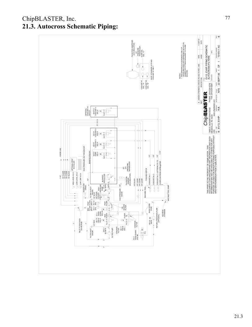
ChipBLASTER, Inc.
77
WA
SH
DO
WN
H
OS
E
RET
UR
N (T
RA
NS
FER
) PU
MP
(OP
TIO
NAL
)
Q1.
3W
AS
H D
OW
NS
OL
BB5
MIC
RO
N F
ILTE
R
N.C
.
5 M
ICR
ON
FIL
TER
Q0.
1.1
RU
N B
SO
L L
149
MIC
RO
NFI
LTE
RFI
LTE
R
"B"
EV
13, E
VHP
AU
TOC
RO
SS
FIL
TER
SE
V13
, EV
HP
PIP
ING
SC
HEM
ATI
C
R.B
.22
SE
PT
06T3
1EV
-1 A
C1
1B
NTS
PO
STFI
LTER
I0.0
.12
3PS
PO
STFI
LTE
R
DIR
TY
1"
FILT
ER
INLE
T
GA
UG
E
BAG
FILT
ER
D
IRTY
1"1"
INLE
T FI
LTE
R S
OC
K
300
MIC
RO
N
N.C
.
1/4"
RE
D
Q0.
0.1
2MTR
1"
1/2"
NO
TE 2
BLO
WO
FF
RE
GU
LATE
RQ
1.0
1MTR
H
IGH
PR
ESS
UR
E
PU
MP
OP
TIO
NA
LC
OO
LER
(Q0.
0.1)
1/4"
BLU
E
1"
M
CO
OLA
NT
No.
3 (
OP
TIO
NA
L E
V 13
)
1PT
PR
ESS
UR
ETR
AN
SD
UC
ER
1/4"
BLA
CK
1/4" P
ULS
ATI
ON
DAM
PE
R(A
CC
UM
ULA
TOR
)
HIG
H P
RES
SU
RE
G
AU
GE
PT
CO
OLA
NT
No.
2
CO
OLA
NT
No.
1
1/4"
CLE
AR
1/4"
CLE
AR
1/4"
CLE
AR
MAC
HIN
E T
OO
L
M
Q0.
0.9
3M
TR
N.C
.
MA
NIF
OLD
BLO
CK
N.C
.
Q0.
0.5
CO
OLA
NT
1
SO
L A
N.O
.Q0.
0.7
DU
MP
SO
L C
N.C
.
Q
0.0.
6C
OO
LAN
T 2
S
OL
B
OPT
ION
ALC
OO
LAN
T #
3O
UTL
ET
Q
0.Q
1.2
CO
OLA
NT
3
SO
L D
N.C
.
1"
TOO
LIN
G O
RFI
CE
1/2"
1/2"
1/2"
OV
ER
FLO
W F
RO
M C
HIP
BLA
STE
R
MAC
HIN
E T
OO
L SU
MP
1-1/
2"
NO
TES
:1.
TH
IS D
RA
WIN
G IS
A S
CH
EM
ATI
C O
NLY
OF
P
IPIN
G A
ND
DO
ES
NO
T R
EP
RE
SEN
T AN
AC
TUAL
N
UM
BE
R O
F FI
TTIN
GS
RE
QU
IRED
TO
PLU
MB
M
AC
HIN
E.
DU
MP
SO
L. S
OL.
"C"
1PT
PR
ES
SUR
ETR
AN
SDU
CE
R
PU
LSA
TIO
N D
AM
PEN
ER
(A
CC
UM
ULA
TOR
)
CO
OLA
NT
#1 S
OL.
"A"
CO
OLA
NT
#2 S
OL.
"B"
NO
TE: S
TAN
DA
RD
JV
10 H
AS
C
OO
LAN
T #1
ON
LY.
#20
ME
SH
S
TRA
INE
R
B A
DD
ED
STR
AIN
ER
& C
HE
CK
VA
LVE
S T
O R
ET.
LIN
EW
PA
11 S
EP
07
N.O
.
1/4"
CLE
AR
1/4"
BLA
CK
1/4"
CLE
AR
1/4"
CLE
AR
1-1/
2"O
VER
FLO
W
OPT
ION
AL
DR
OP
IN
CH
ILLE
R
HIG
H P
RE
SSU
RE
UN
IT R
ES
ER
VOIR
FILT
ER
OU
TLE
T
G
AU
GE
LOW
LIM
IT I0
.0. 4
HIG
H L
EV
EL
I0.0
.3
LOW
LE
VE
L I0
.0.2
RE
SER
VO
IR
DR
AIN
FILT
ER
PU
MP
M
1"
Q1.
3W
AS
HD
OW
N
SO
L A
A
Q0.
1.0
RU
N A
SO
L K
I0.0
.12P
S
BA
GFI
LTE
R
21.3. Autocross Schematic Piping:
21.3
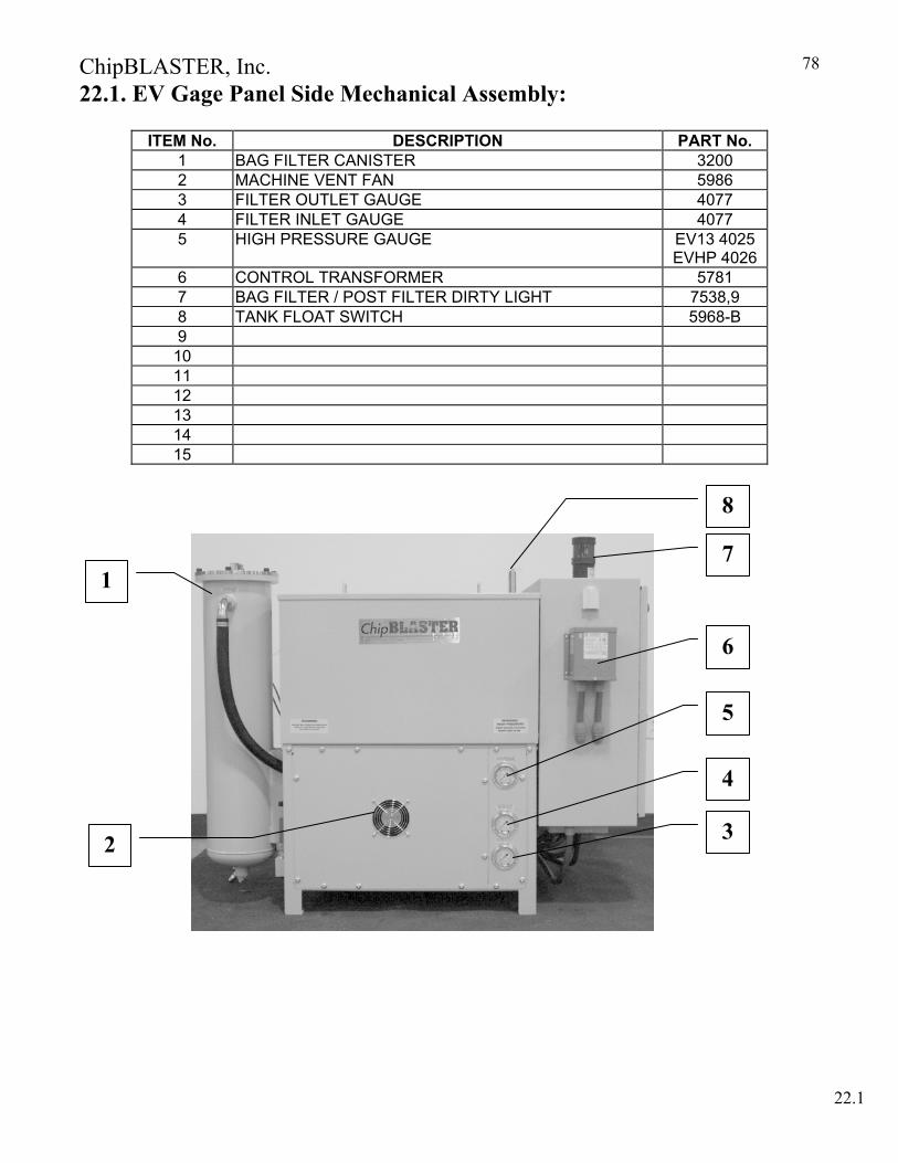
ChipBLASTER, Inc.
78
22.1. EV Gage Panel Side Mechanical Assembly:
ITEM No. DESCRIPTION PART No. 1 BAG FILTER CANISTER 3200 2 MACHINE VENT FAN 5986 3 FILTER OUTLET GAUGE 4077 4 FILTER INLET GAUGE 4077 5 HIGH PRESSURE GAUGE EV13 4025
EVHP 4026 6 CONTROL TRANSFORMER 5781 7 BAG FILTER / POST FILTER DIRTY LIGHT 7538,9 8 TANK FLOAT SWITCH 5968-B 9
10 11 12 13 14 15
1
2 3
4
5
6
22.1
8
7
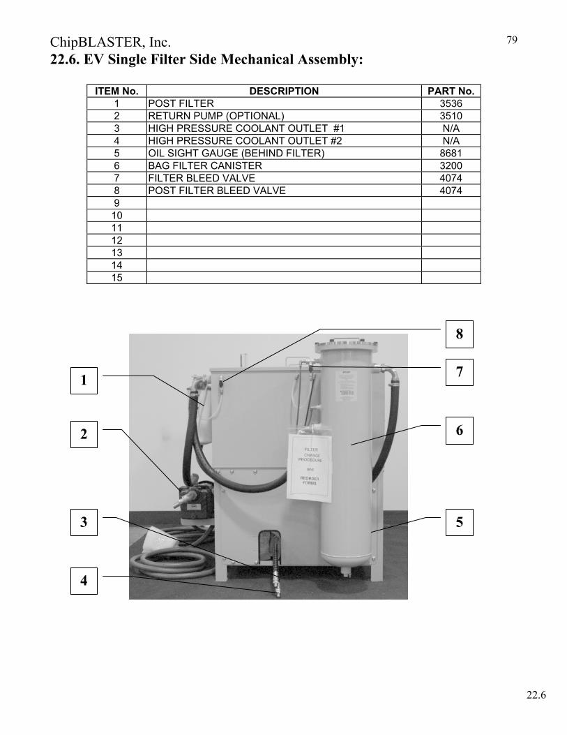
ChipBLASTER, Inc.
79
22.6. EV Single Filter Side Mechanical Assembly:
ITEM No. DESCRIPTION PART No. 1 POST FILTER 3536 2 RETURN PUMP (OPTIONAL) 3510 3 HIGH PRESSURE COOLANT OUTLET #1 N/A 4 HIGH PRESSURE COOLANT OUTLET #2 N/A 5 OIL SIGHT GAUGE (BEHIND FILTER) 8681 6 BAG FILTER CANISTER 3200 7 FILTER BLEED VALVE 4074 8 POST FILTER BLEED VALVE 4074 9
10 11 12 13 14 15
1
2
3
4
5
6
7
8
22.6
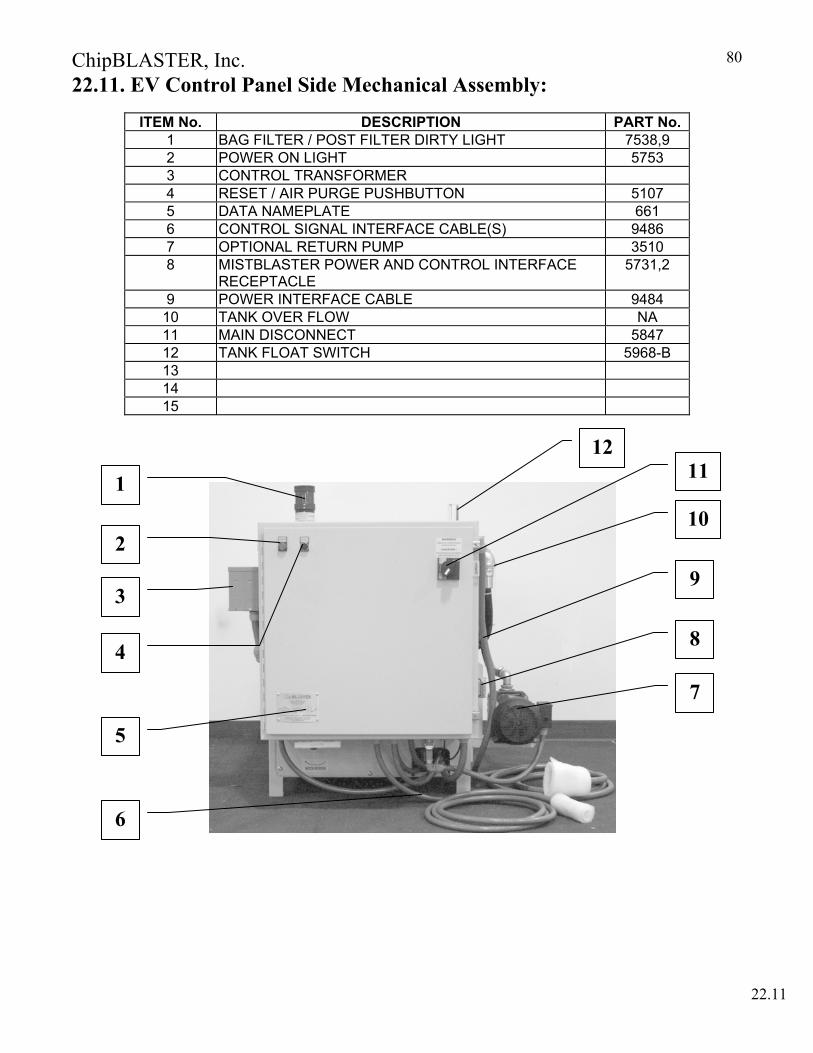
ChipBLASTER, Inc.
80
22.11. EV Control Panel Side Mechanical Assembly:
ITEM No. DESCRIPTION PART No.1 BAG FILTER / POST FILTER DIRTY LIGHT 7538,9 2 POWER ON LIGHT 5753 3 CONTROL TRANSFORMER 4 RESET / AIR PURGE PUSHBUTTON 5107 5 DATA NAMEPLATE 661 6 CONTROL SIGNAL INTERFACE CABLE(S) 9486 7 OPTIONAL RETURN PUMP 3510 8 MISTBLASTER POWER AND CONTROL INTERFACE
RECEPTACLE 5731,2
9 POWER INTERFACE CABLE 9484 10 TANK OVER FLOW NA 11 MAIN DISCONNECT 5847 12 TANK FLOAT SWITCH 5968-B 13 14 15
1
2
3
4
5
7
6
22.11
8
9
10
1112

ChipBLASTER, Inc.
81
22.16. EV Filter Mechanical Assembly:
ITEM No. DESCRIPTION PART No.1 FILTER LID WITH BAG HOLD DOWN 3201A “O” RING SEAL 8” (NOT SHOWN) 2571
2 FILTER BAG 8” x 30” (5 Micron) 3013-5 3 BASKET SCREEN 8” 3024-R2 4 FILTER HOUSING JV and EV 3200 5 FLUID OUTLET N/A 6 FILTER DRAIN N/A 7 FILTER MOUNTING BRACKET 8700-17 8 FLUID INLET N/A 9 GAUGE PORT (USED ON “J” UNITS ONLY) N/A
10 FILTER BLEED (AIR PURGE) USED ON JV,EV,GV,CV N/A
22.16
1
2
3
4
5
9
6
7
8
10
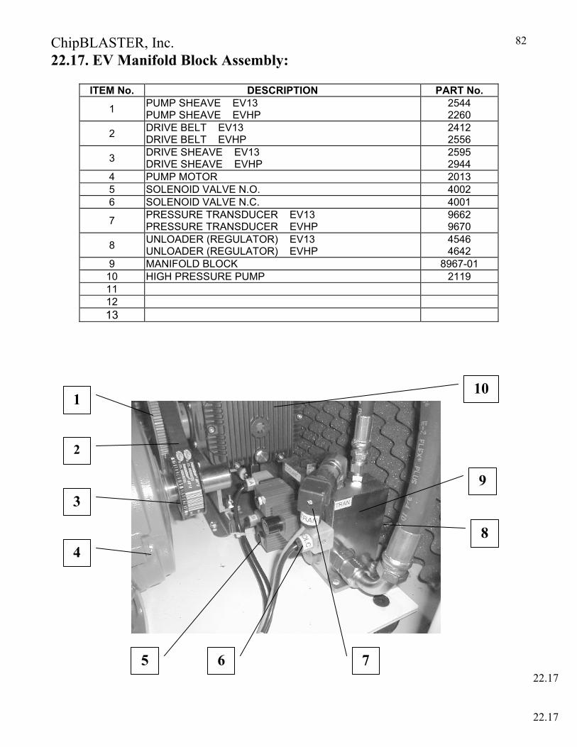
ChipBLASTER, Inc.
82
22.17. EV Manifold Block Assembly: ITEM No. DESCRIPTION PART No.
1 PUMP SHEAVE EV13 PUMP SHEAVE EVHP
2544 2260
2 DRIVE BELT EV13 DRIVE BELT EVHP
2412 2556
3 DRIVE SHEAVE EV13 DRIVE SHEAVE EVHP
2595 2944
4 PUMP MOTOR 2013 5 SOLENOID VALVE N.O. 4002 6 SOLENOID VALVE N.C. 4001
7 PRESSURE TRANSDUCER EV13 PRESSURE TRANSDUCER EVHP
9662 9670
8 UNLOADER (REGULATOR) EV13 UNLOADER (REGULATOR) EVHP
4546 4642
9 MANIFOLD BLOCK 8967-01 10 HIGH PRESSURE PUMP 2119 11 12 13
7 6
2
3
1
8
5
22.17
4
9
10
22.17
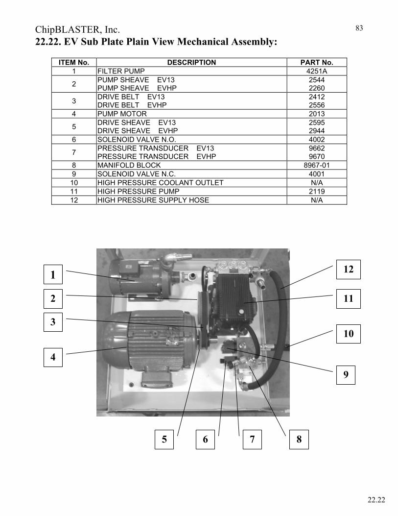
ChipBLASTER, Inc.
83
22.22. EV Sub Plate Plain View Mechanical Assembly: ITEM No. DESCRIPTION PART No.
1 FILTER PUMP 4251A
2 PUMP SHEAVE EV13 PUMP SHEAVE EVHP
2544 2260
3 DRIVE BELT EV13 DRIVE BELT EVHP
2412 2556
4 PUMP MOTOR 2013
5 DRIVE SHEAVE EV13 DRIVE SHEAVE EVHP
2595 2944
6 SOLENOID VALVE N.O. 4002
7 PRESSURE TRANSDUCER EV13 PRESSURE TRANSDUCER EVHP
9662 9670
8 MANIFOLD BLOCK 8967-01 9 SOLENOID VALVE N.C. 4001
10 HIGH PRESSURE COOLANT OUTLET N/A 11 HIGH PRESSURE PUMP 2119 12 HIGH PRESSURE SUPPLY HOSE N/A
6
1
2
8 7 5
4
3
9
10
11
12
22.22

ChipBLASTER, Inc.
84
22.27. EV Oil Level Sight Mechanical Assembly:
ITEM No. DESCRIPTION PART No.1 OIL SIGHT GAUGE ASSEMBLY 8681 2 3 4 5 6 7 8 9
10
1
22.27
OIL LEVEL LABEL
OIL DRAIN PLUG
22.27
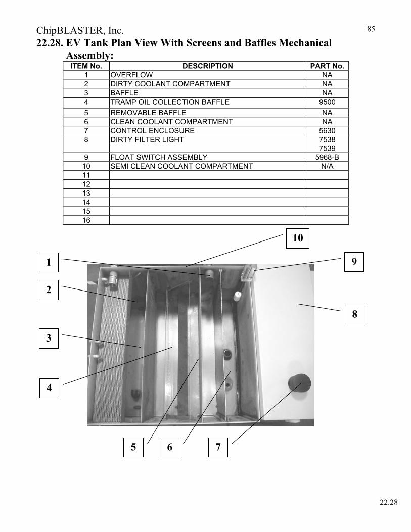
ChipBLASTER, Inc.
85
22.28. EV Tank Plan View With Screens and Baffles Mechanical Assembly:
ITEM No. DESCRIPTION PART No.1 OVERFLOW NA 2 DIRTY COOLANT COMPARTMENT NA 3 BAFFLE NA 4 TRAMP OIL COLLECTION BAFFLE 9500 5 REMOVABLE BAFFLE NA 6 CLEAN COOLANT COMPARTMENT NA 7 CONTROL ENCLOSURE 5630 8 DIRTY FILTER LIGHT 7538
7539 9 FLOAT SWITCH ASSEMBLY 5968-B
10 SEMI CLEAN COOLANT COMPARTMENT N/A 11 12 13 14 15 16
1
2
4
3
8
9
22.28
5 6 7
10
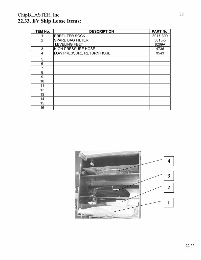
ChipBLASTER, Inc.
86
22.33. EV Ship Loose Items:
ITEM No. DESCRIPTION PART No.1 PREFILTER SOCK 3017-300 2 SPARE BAG FILTER
LEVELING FEET 3013-5 8269A
3 HIGH PRESSURE HOSE 4736 4 LOW PRESSURE RETURN HOSE 9543
5 6 7 8 9
10 11 12 13 14 15 16
22.33
1
3
2
4

ChipBLASTER, Inc.
87
ITEMNo. DESCRIPTION PART No.
EVKIT PART
NO.
EVHPKIT PART
NO.30017 30017HP
QT'Y. / KIT QT'Y. / KIT
1 SOLENOID VALVEN.O. 4002 1 1
2 SOLENOID VALVEN.C. 4001 1 1
3 UNLOADER(REGULATOR)3000 PSIG 4546 1 1
4 UNLOADER(REGULATOR)5000 PSIG 4642 0 1
5 TRANSDUCER 0 - 2000 PSIG 9662 1 06 TRANSDUCER 0 - 5000 PSIG 9670 0 1
7
HIGH PRESSURE PUMPNOT INCLUDED IN SPARE PARTS KIT
FOR REFERENCE ONLY
2119 1 1
8 MAIN DRIVE BELT 2412 1 09 MAIN DRIVE BELT 2611 0 010 MAIN DRIVE BELT 2621 0 011 MAIN DRIVE BELT 2556 0 112 MAIN DRIVE BELT 2938 0 013 PRESSURE SWITCH 9668 1 1
SPARE PARTS
22.38 EV13, EVHP Spare Parts (Recommended) Listing:
22.13 22.35 22.38
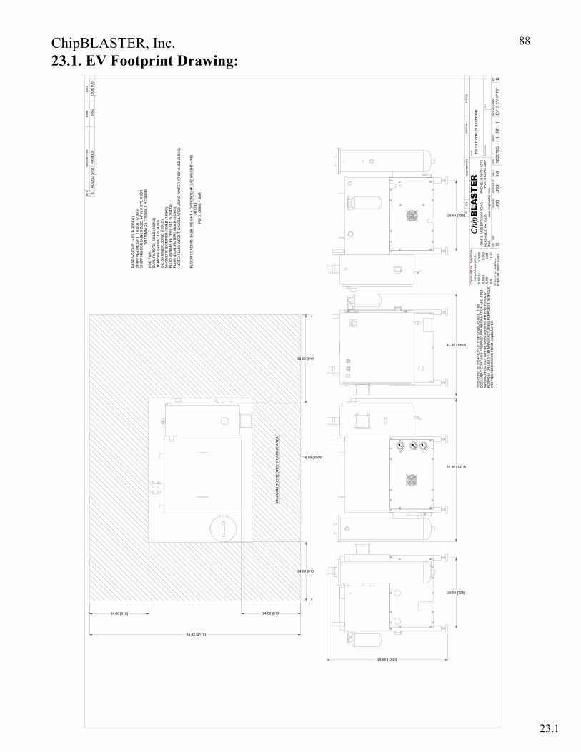
ChipBLASTER, Inc.
88
23.1. EV Footprint Drawing:
23.1
28.56 [725]
41.45 [1053]
28.56 [725]
57.98 [1473]
EV1
3 EV
HP
FO
OTP
RIN
T
JRG
JRG
12O
CT0
5EV
13 E
VH
P FP
11
B1:
8
48.80 [1240]
MIN
IMU
M S
UG
GE
STED
WO
RKI
NG
AR
EA
116.09 [2949]
24.00 [610]
36.00 [914]
85.42 [2170]
24.00 [610] 24.00 [610]
BA
SE W
EIG
HT:
140
0LB
(635
KG)
SH
IPP
ING
WE
IGH
T: 1
700L
B (7
71KG
)S
HIP
PIN
G C
ON
TAIN
ER
SIZ
E: 4
8"W
X 6
7"L
X 5
3"H
W12
19M
M X
L17
02M
M X
H13
46M
MA
DD
FO
R:
DU
AL
FILT
ERS
: 220
LB (1
00KG
)TR
AN
SFE
R P
UM
P: 1
00 (4
5KG
)O
IL S
KIM
ME
R: 3
00LB
(136
KG)
MA
GN
ETIC
SK
IMM
ER
: 300
LB (1
36KG
)FL
UID
(SIN
GLE
FIL
TER
): 58
1LB
(264
KG)
FLU
ID (D
UA
L FI
LTE
R):
664L
B (3
02KG
) N
OTE
: FLU
ID W
EG
HT
CAL
CU
LATE
D U
SIN
G W
ATER
AT
68° 8
.3LB
(3.8
KG)
FLO
OR
LO
AD
ING
: BA
SE W
EIG
HT
+ O
PTIO
N(S
) +FL
UID
WEI
GH
T =
PSI
28.
2744
P
SI X
.068
95 =
BAR
BA
DD
ED S
PLIT
PA
NE
LSJR
G12
OC
T05

ChipBLASTER, Inc.
89
24.0. WARRANTY: 24.1. WARRANTY (LIMITED) – NEW EQUIPMENT ChipBLASTER, Inc. Limited Warranty - New Equipment
Limited Warranty. ChipBLASTER, Inc. warrants its ChipBLASTER™ high-pressure coolant systems to be free from defects in materials and workmanship for the lesser of one year or 4160 hours of operation from the date of original installation, subject to the conditions set forth below. During this warranty period, ChipBLASTER will repair or replace, at its sole option, defective products or parts without charge to the purchaser. Limited Warranty Conditions:
24.1.1 Limited warranty applies only to new ChipBLASTER equipment, and is solely for the benefit of and applicable to the end user.
24.1.2 This limited warranty does not apply to any damage, failure, defect or loss caused by any or all of the following circumstances or conditions: failure to follow instructions or observe cautions and warnings relating to installation, operation, applications, inspection and “regular maintenance” 1, as specified in this warranty and/or any ChipBLASTER manual, quotation, acknowledgment, spec. sheet or installation instructions (all of which shall hereinafter be referred to as “applicable literature”); use of ChipBLASTER equipment outside the parameters of “normal usage” including, but not limited to, misapplication, misuse, failure to follow directions and instructions provided by ChipBLASTER applicable literature; any damage or loss to products or parts which results from the alteration, repair, modification, faulty installation, or service (other than regular maintenance) by any one other than an authorized ChipBLASTER service technician; the use of any add-ons, parts, accessories or components not obtained from ChipBLASTER or an authorized ChipBLASTER supplier or approved in writing by ChipBLASTER; damage to products or parts caused by accident, abuse or misuse; replacement of filters1; normal wear and tear; damage which occurs in shipment or as a result of an act of God, such as lightening, or electrical failures such as line surges or brownouts.
24.1.3. Any replacement equipment or parts provided to the purchaser in fulfilling this warranty are warranted for the un-expired portion of the original warranty.
24.1.4. If any ChipBLASTER products are found upon ChipBLASTER’s examination in response to a warranty claim to have defects in material or workmanship, ChipBLASTER will either replace or repair the product, at its sole option.
24.1.5. ChipBLASTER expects that warranty repairs will be completed at the purchaser’s location; however, if requested by ChipBLASTER, purchaser shall return the alleged defective product to ChipBLASTER for examination, at ChipBLASTER’s direction. ChipBLASTER will reimburse the purchaser for the expense incurred in returning any product to ChipBLASTER if ChipBLASTER has provided prior written authorization to the purchaser and the problem is covered by this warranty. In the event the problem is not covered by this limited warranty, ChipBLASTER will not be responsible for payment of shipping expense.
24.1.6. Other than the obligations imposed upon ChipBLASTER under this limited warranty, ChipBLASTER shall not be liable for any other costs, expenses or losses that the purchaser incurs to remedy any defect.
1 Regular maintenance includes the minor normal maintenance required to be performed by buyer, at buyer’s expense as set forth in the maintenance schedule included with this warranty as Exhibit A and posted on the outside panel of the ChipBLASTER. Use of filters other than ChipBLASTER will void warranty coverage for any filtration related damage or failures.
24.1
ChipBLASTER, Inc.
90
24.0. WARRANTY (Cont.): 24.1.7. Repairs of defects in material or workmanship during the limited warranty period
shall be performed only by ChipBLASTER approved service technicians; the cost of repairs performed by others will not be reimbursed by ChipBLASTER unless prior approval is received in writing from ChipBLASTER.
24.1.8. This limited warranty shall cover alleged defects in materials and workmanship
about which ChipBLASTER receives notice within thirty (30) days of either the discovery of the alleged defect or the expiration of the limited warranty period, whichever is earlier. Any claim not made within this time shall be conclusively deemed to having been waived by the purchaser.
24.1.9. Failure of the purchaser to maintain the equipment by completing all of the scheduled maintenance tasks set forth in Exhibit A to this limited warranty entitled “ChipBLASTER Maintenance Schedule” will void this limited warranty, and release ChipBLASTER from any liability hereunder. ChipBLASTER may require purchaser to provide evidence of timely completion of the scheduled maintenance tasks set forth in Exhibit A.
24.1.10. ChipBLASTER warranty card must be completed by purchaser and returned to ChipBLASTER within 30 days after installation of ChipBLASTER equipment to validate this limited warranty.
Procedures for Obtaining Technical Service or Warranty Service. Repair or replacement under this limited warranty can only be obtained by registering a warranty claim directly with ChipBLASTER. To enable ChipBLASTER to respond to a request for technical assistance or a request for warranty service, the purchaser must provide, at a minimum, the following information during the initial telephone call: model number, serial number and information regarding any optional ChipBLASTER™ components; the date of purchase; the dealer or supplier from whom the equipment was purchased and the nature of the problem or difficulty. A warranty claim form can be obtained by contacting ChipBLASTER at 800-241-3163. Limitation of Liability. ChipBLASTER’s liability under this warranty is limited as set forth herein. This limited warranty and the remedies set forth herein constitute the sole and exclusive remedy available to the purchaser of ChipBLASTER™ equipment covered by this limited warranty, and are in lieu of any or all other remedies, whether based on statements or promises which are oral, written, express or implied, and whether in contract, tort, equity or otherwise. ChipBLASTER neither extends nor provides any warranty, expressed or implied, on any products not manufactured by or sold by ChipBLASTER. Problems caused to ChipBLASTER™ equipment or other equipment by products used in conjunction with ChipBLASTER™ equipment which are not either manufactured by ChipBLASTER or manufactured to design specifications provided by ChipBLASTER and specifically approved by ChipBLASTER in writing are not the responsibility of ChipBLASTER, either under this warranty, or otherwise. This warranty excludes all implied warranties of merchantability or fitness for particular purpose or any purpose. This warranty specifically excludes reimbursement or liability for “downtime,” loss of income and/or consequential damages. In no event will ChipBLASTER’s liability to the purchaser resulting from any claim or loss arising out of a purchaser’s purchase of ChipBLASTER™ equipment or the operation thereof exceed the purchase price of the product manufactured or sold by ChipBLASTER.
24.1

ChipBLASTER, Inc.
91
24.0. WARRANTY (Cont.): 24.2 WARRANTY (LIMITED) – USED EQUIPMENT ChipBLASTER, Inc. Limited Warranty - Used Equipment
Limited Warranty. ChipBLASTER, Inc. warrants the used ChipBLASTER™ high-pressure coolant systems to be free from defects in materials and workmanship for the lesser of 90 days or 1040 hours from the date of installation, subject to the conditions set forth below. During this warranty period, ChipBLASTER will repair or replace, at its sole option, defective products or parts without charge to the purchaser. Limited Warranty Conditions:
24.2.1 Limited warranty applies only to used ChipBLASTER equipment, and is solely for the benefit of and applicable to initial purchaser.
24.2.2 This limited warranty does not apply to any damage, failure, defect or loss caused by any or all the following circumstances or conditions: failure to follow instructions or observe cautions and warnings relating to installation, operation, applications, inspection and regular maintenance2, as specified in this manual and/or any ChipBLASTER manual, quotation, acknowledgment, sales literature, spec sheet or installation instructions (all of which shall hereinafter be referred to as “applicable literature”); use of ChipBLASTER equipment outside the parameters of “normal usage” including, but not limited to misapplication, misuse, failure to follow directions and instructions provided by ChipBLASTER applicable literature; any damage or loss to products or parts which results from the alteration, repair, modification, faulty installation, or service (other than regular maintenance) by any one other than an authorized ChipBLASTER service technician and the use of any add-ons, parts, accessories or components not obtained from ChipBLASTER or an authorized ChipBLASTER supplier or approved in writing by ChipBLASTER; damage to products or parts caused by accident, abuse or misuse; replacement of filters1; normal wear and tear; damage which occurs in shipment or as a result of an act of God, such as lightening, or electrical failures such as line surges or brownouts.
24.2.3. Any replacement equipment or parts provided to the purchaser in fulfilling this warranty are warranted for the un-expired portion of the original warranty.
24.2.4. If any ChipBLASTER products are found upon ChipBLASTER’s examination in response to a warranty claim to have defects in material or workmanship, ChipBLASTER will either replace or repair the product, at its sole option.
24.2.5. ChipBLASTER expects that warranty repairs will be completed at the purchaser’s location; however, if requested by ChipBLASTER, purchaser shall return the alleged defective product to ChipBLASTER for examination, at ChipBLASTER’s direction. ChipBLASTER will reimburse the purchaser for the expense incurred in returning any product to ChipBLASTER if ChipBLASTER has provided prior written authorization to the purchaser and the problem is covered by this warranty. In the event the problem is not covered by this limited warranty, ChipBLASTER will not be responsible for payment of shipping expense.
2Regular maintenance includes the minor normal maintenance required to be performed by buyer, at buyer’s expense as set forth in the maintenance schedule included with this warranty as Exhibit A and posted on the outside panel of the ChipBLASTER. Use of filters other than ChipBLASTER will void warranty coverage for any filtration related damage or failures.
24.2
ChipBLASTER, Inc.
92
24.0. WARRANTY (Cont.):
24.2.6. Other than the obligations imposed upon ChipBLASTER under this limited warranty, ChipBLASTER shall not be liable for any other costs, expenses or losses that the purchaser incurs to remedy any defect.
24.2.7. Repairs of defects in material or workmanship during the limited warranty period
shall be performed only by ChipBLASTER approved service technicians; the cost of repairs performed by others will not be reimbursed by ChipBLASTER unless prior approval is received in writing from ChipBLASTER.
24.2.8. This limited warranty shall cover alleged defects in materials and workmanship about which ChipBLASTER receives notice within thirty (30) days of either the discovery of the alleged defect or the expiration of the limited warranty period, whichever is earlier. Any claim not made within this time shall be conclusively deemed to have been waived by the purchaser.
24.2.9. Failure of the purchaser to maintain the equipment by completing all of the scheduled maintenance tasks set forth in Exhibit A to this limited warranty entitled “ChipBLASTER Maintenance Schedule” will void this limited warranty, and release ChipBLASTER from any liability hereunder. ChipBLASTER may require purchaser to provide evidence of timely completion of the scheduled maintenance tasks set forth in Exhibit A.
24.2.10. ChipBLASTER warranty card must be completed by purchaser and returned to ChipBLASTER within 30 days after installation of ChipBLASTER equipment to validate this limited warranty.
Procedures for Obtaining Technical Service or Warranty Service. Repair or replacement under this limited warranty can only be obtained by registering a warranty claim directly with ChipBLASTER. To enable ChipBLASTER to respond to a request for technical assistance or a request for warranty service, the purchaser must provide, at a minimum, the following information during the initial telephone call: model number, serial number and information regarding any optional ChipBLASTER™ components; the date of purchase; the dealer or supplier from whom the equipment was purchased; the nature of the problem or difficulty. A warranty claim form can be obtained by contacting ChipBLASTER at 800-241-3163. Limitation of Liability. ChipBLASTER’s liability under this warranty is limited as set forth herein. This limited warranty and the remedies set forth herein constitute the sole and exclusive remedy available to the purchaser of ChipBLASTER™ equipment covered by this limited warranty, and are in lieu of any or all other remedies, whether based on statements or promises which are oral, written, express or implied, and whether in contract, tort, equity or otherwise. ChipBLASTER neither extends nor provides any warranty, expressed or implied, on any products not manufactured by or sold by ChipBLASTER. Problems caused to ChipBLASTER™ equipment or other equipment by products used in conjunction with ChipBLASTER™ equipment which are not either manufactured by ChipBLASTER or manufactured to design specifications provided by ChipBLASTER and specifically approved by ChipBLASTER in writing are not the responsibility of ChipBLASTER, either under this warranty, or otherwise. This warranty excludes all implied warranties of merchantability or fitness for particular purpose or any purpose. This warranty specifically excludes reimbursement or liability for “downtime,” loss of income and/or consequential damages. In no event will ChipBLASTER’s liability to the purchaser resulting from any claim or loss arising out of a purchaser’s purchase of ChipBLASTER™ equipment or the operation thereof exceed the purchase price of the product manufactured or sold by ChipBLASTER.
24.2

ChipBLASTER, Inc.
93
24.0. WARRANTY (Cont.): 24.3. WARRANTY (LIMITED) – RETROFITS ChipBLASTER, Inc. Limited Warranty - High Pressure Retrofits
Limited Warranty. ChipBLASTER, Inc. warrants its ChipBLASTER™ high-pressure retrofits to be free from defects in materials and workmanship for the lesser of one year or 4160 operating hours from the date of delivery to the original user, subject to the conditions set forth below. During this warranty period, ChipBLASTER will repair or replace, at its sole option, defective products or parts without charge to the purchaser. ChipBLASTER, Inc. further warrants that its ChipBLASTER™ high-pressure retrofit systems will not adversely affect or damage the cutting equipment on which ChipBLASTER installs such systems. Limited Warranty Conditions:
24.3.1. Warranty applies only to new ChipBLASTER retrofits. 24.3.2. This limited warranty does not apply to any damage, failure, defect or loss
caused by any or all the following circumstances or conditions: failure to follow instructions or observe cautions and warnings relating to installation, operation, applications, inspection and regular3 maintenance, as specified in any ChipBLASTER manual, quotation, acknowledgment, sales literature, spec sheet or installation instructions (all of which shall hereinafter be referred to as “applicable literature”); use of ChipBLASTER retrofits outside the parameters of “normal usage” including, but not limited to misapplication, misuse, failure to follow directions and instructions provided by ChipBLASTER applicable literature; any damage or loss to products or parts which results from the alteration, repair, modification, faulty installation, or service (other than regular maintenance) by any one other than an authorized ChipBLASTER service technician and the use of any add-ons, parts, accessories or components not obtained from ChipBLASTER or an authorized ChipBLASTER supplier or approved in writing by ChipBLASTER; damage to products or parts caused by accident, abuse or misuse; normal wear and tear; damage which occurs in shipment or as a result of an act of God, such as lightening, or electrical failures such as line surges or brownouts.
24.3.3. Any replacement equipment or parts provided to the purchaser in fulfilling this warranty are warranted for the un-expired portion of the original warranty.
24.3.4. If any ChipBLASTER products are found upon ChipBLASTER’s examination in response to a warranty claim to have defects in material or workmanship, ChipBLASTER will either replace or repair the product, at its sole option.
24.3.5. Warranty repairs will be completed at the purchaser’s location. 24.3.6. Other than the obligations imposed upon ChipBLASTER under this limited
warranty, ChipBLASTER shall not be liable for any other costs, expenses or losses that the purchaser incurs to remedy any defect.
24.3.7. Repairs of defects in material or workmanship during the limited warranty period shall be performed only by ChipBLASTER approved service technicians; the cost of repairs performed by others will not be reimbursed by ChipBLASTER unless prior approval is received in writing from ChipBLASTER.
3 Regular maintenance includes the minor normal maintenance required to be performed by buyer, at buyer’s expense as set forth in the maintenance schedule included with this warranty as Exhibit A and posted on the outside panel of the ChipBLASTER. Use of filters other than ChipBLASTER will void warranty coverage for any filtration related damage or failures.
24.3

ChipBLASTER, Inc.
94
24.0. WARRANTY (Cont.):
24.3.8. This limited warranty shall cover alleged defects in materials and workmanship about which ChipBLASTER receives notice within thirty (30) days of either the discovery of the alleged defect or the expiration of the limited warranty period, whichever is earlier. Any claim not made within this time shall be conclusively deemed to have been waived by the purchaser.
24.3.9. ChipBLASTER warranty card must be completed by purchaser and returned to ChipBLASTER within 30 days after installation of ChipBLASTER retrofits.
Procedures for Obtaining Technical Service or Warranty Service. Repair or replacement under this limited warranty can only be obtained by registering a warranty claim directly with ChipBLASTER. To enable ChipBLASTER to respond to a request for technical assistance or a request for warranty service, the purchaser must provide, at a minimum, the following information during the initial telephone call: model and serial number of the equipment on which the ChipBLASTER retrofit was installed; information regarding the installed ChipBLASTER retrofit; the date of purchase; the dealer or supplier from whom the equipment was purchased; the nature of the problem or difficulty. A warranty claim form can be obtained by contacting ChipBLASTER at 800-241-3163. Limitation of Liability. ChipBLASTER’s liability under this warranty is limited as set forth herein. This limited warranty and the remedies set forth herein constitute the sole and exclusive remedy available to the purchaser of ChipBLASTER™ retrofits covered by this limited warranty, and are in lieu of any or all other remedies, whether based on statements or promises which are oral, written, express or implied, and whether in contract, tort, equity or otherwise. ChipBLASTER neither extends nor provides any warranty, expressed or implied, on any products not manufactured by or sold by ChipBLASTER. Problems caused to ChipBLASTER™ retrofits used in conjunction with ChipBLASTER™ equipment which are not either manufactured by ChipBLASTER or manufactured to design specifications provided by ChipBLASTER and specifically approved by ChipBLASTER in writing are not the responsibility of ChipBLASTER, either under this warranty, or otherwise. This warranty excludes all implied warranties of merchantability or fitness for particular purpose or any purpose. This warranty specifically excludes liability of ChipBLASTER for, “downtime,” loss of income and/or consequential damages. In no event will ChipBLASTER’s liability to the purchaser resulting from any claim or loss arising out of a purchaser’s purchase of ChipBLASTER™ retrofits or the operation thereof exceed the purchase price of the product manufactured or sold by ChipBLASTER.
24.3
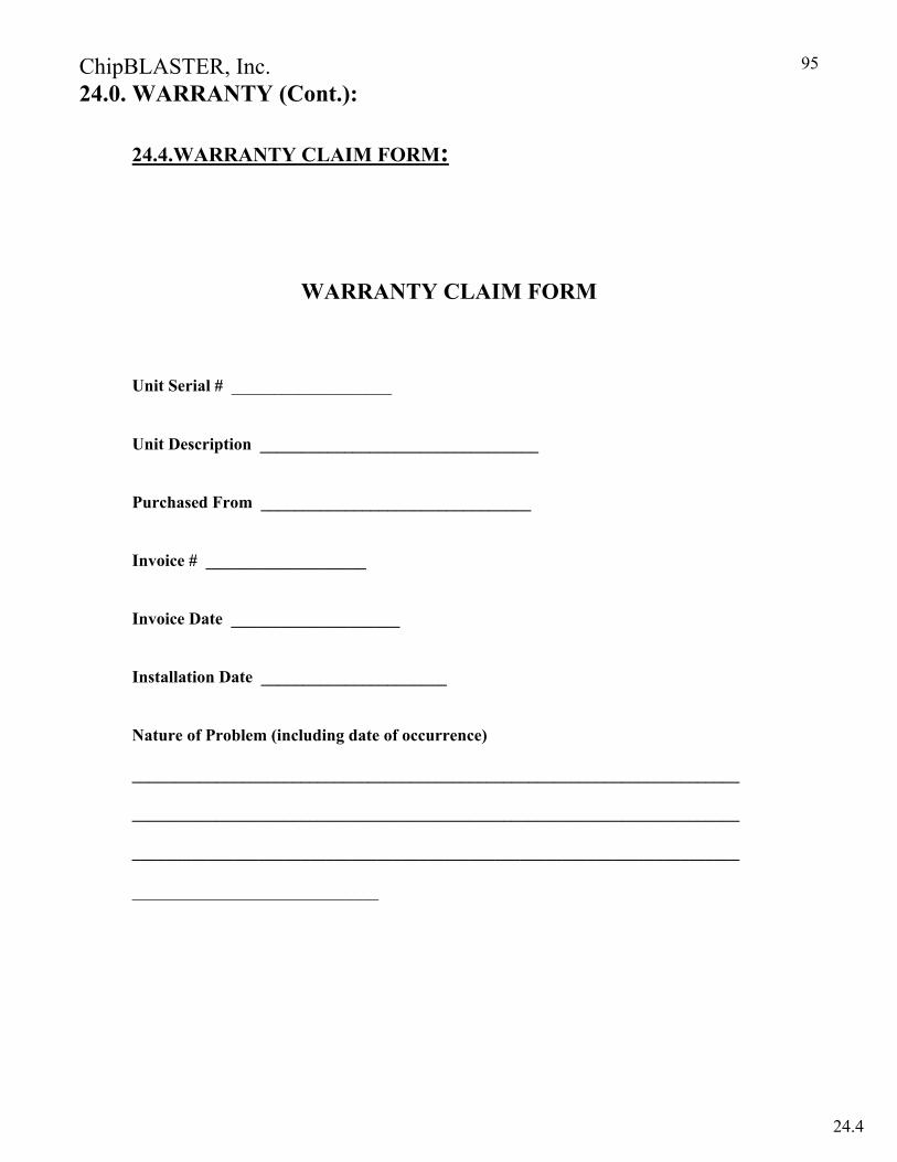
ChipBLASTER, Inc.
95
24.0. WARRANTY (Cont.):
24.4.WARRANTY CLAIM FORM:
WARRANTY CLAIM FORM
Unit Serial # ___________________
Unit Description _________________________________
Purchased From ________________________________
Invoice # ___________________
Invoice Date ____________________
Installation Date ______________________
Nature of Problem (including date of occurrence)
________________________________________________________________________
________________________________________________________________________
________________________________________________________________________
____________________________
24.4
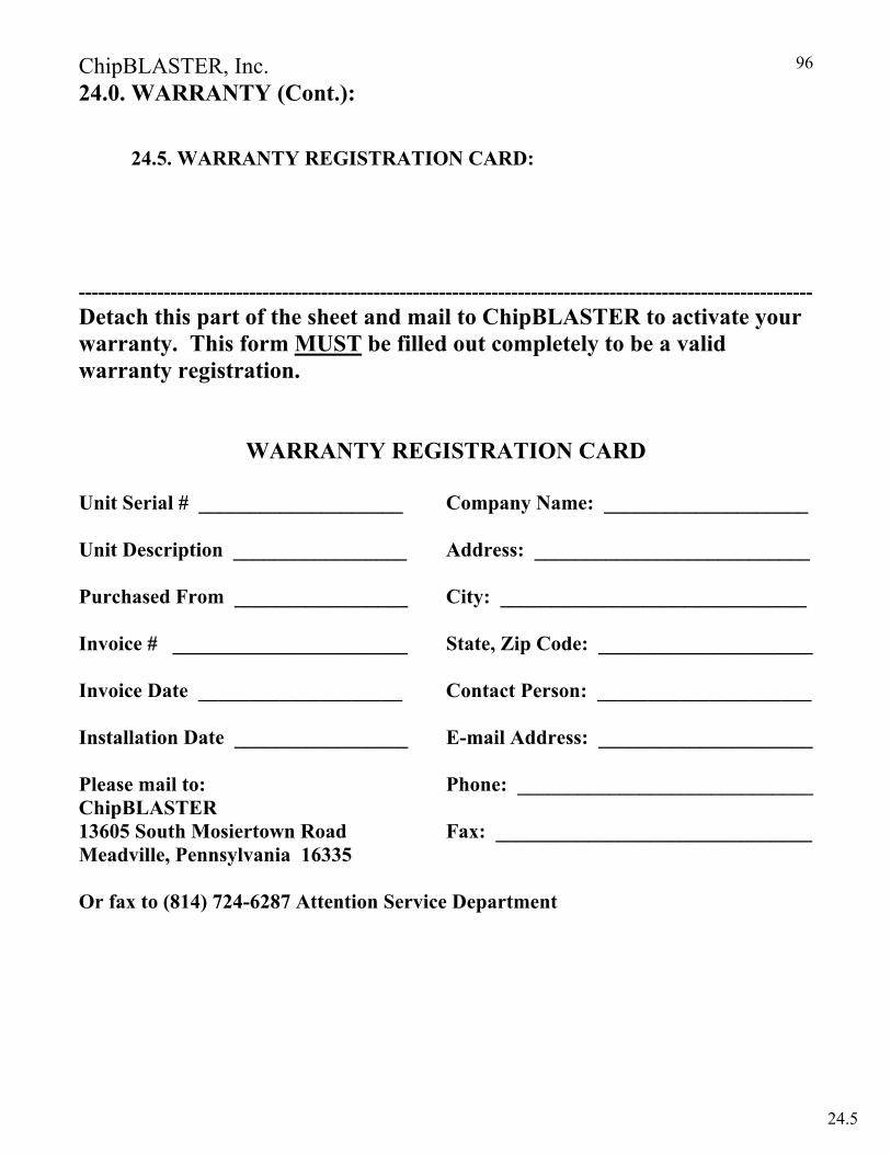
ChipBLASTER, Inc.
96
24.0. WARRANTY (Cont.):
24.5. WARRANTY REGISTRATION CARD:
---------------------------------------------------------------------------------------------------------------- Detach this part of the sheet and mail to ChipBLASTER to activate your warranty. This form MUST be filled out completely to be a valid warranty registration.
WARRANTY REGISTRATION CARD
Unit Serial # ____________________ Company Name: ____________________ Unit Description _________________ Address: ___________________________ Purchased From _________________ City: ______________________________ Invoice # _______________________ State, Zip Code: _____________________ Invoice Date ____________________ Contact Person: _____________________ Installation Date _________________ E-mail Address: _____________________ Please mail to: Phone: _____________________________ ChipBLASTER 13605 South Mosiertown Road Fax: _______________________________ Meadville, Pennsylvania 16335 Or fax to (814) 724-6287 Attention Service Department
24.5

ChipBLASTER, Inc.
97
24.0. WARRANTY (Cont.):
24.6. WARRANTY VALIDATION CARD:
WARRANTY VALIDATION CARD UNIT SERIAL # ___________ Unit Description ___________________________ Installation Date_________________ Purchased From____________________________ Invoice # ___________________ Invoice Date ________________ I _____________________________ on _____________ hereby declare the ChipBlaster Signature date high pressure coolant system has been installed on ______________________ according machine model to ChipBlaster procedures (Note: ChipBlaster Standard Warranty will commence with the above signed date if all conditions of the procedures are met). SEND TO: ChipBLASTER (Office Use Only) 13605 South Mosiertown Road Date Warranty Registration Received __________ Meadville, PA 16335 Attn: Warranty Dept.
24.6

ChipBLASTER, Inc.
98
27.0. OPTIONAL EQUIPMENT: 27.1 Magelis Human machine interface Unit (HMI)
27.1.1 Used to display in plain English, operating status, and faults. 27.1.2 During normal operation the status of the of the coolant system
will be displayed on the operator interface unit. The following information will be displayed: 27.1.2.1.Coolant No. 1 ON ( Will show filter being used [A or B] when autocross option is being used). 27.1.2.2. Coolant No. 2 ON ( Will show filter being used [A or B] when
autocross option is being used). 27.1.2.3. Coolant No. 1 and 2 ( Will show filter being used [A or B] when autocross option is being used). 27.1.2.4. Index No. 1 ON ( Will show filter being used [A or B] when
autocross option is being used). 27.1.2.5. Index No. 2 ON ( Will show filter being used [A or B] when
autocross option is being used). 27.1.2.6. Index No. 1 and 2 ON ( Will show filter being used [A or B] when
autocross option is being used). 27.1.3. Faults that will be displayed are:
27.1.3.1. Filter dirty (single filter system). 27.1.3.2. Filter “A” dirty (autocross system).
27.1.3.3. Filter “B” dirty (autocross system). 27.1.3.4. Post filter dirty.
27.1.3.5. Drive Fault. 27.1.3.6. Slow coolant return. 27.1.3.7. Low pressure lockout (Optional Pressure Switch Required). 27.1.3.8. Low coolant limit. 27.1.3.9 Circuit breaker or Overload trip.
27.1.4. Available as part of the operator interface is a provision to view the last eight (8) faults. To view the past eight (8) faults press the DOWN ARROW key while the coolant system is stopped and not in a fault condition. The display uses a last in last out sequence that is the last fault that occurred will be the first fault displayed. Each press of the DOWN ARROW key will display a fault until the pass eight have been stepped through at which time the display will revert to the start up screen. If there is no fault stored in any of the past eight (8) storage locations a message will indicate “NO FAULT STORED IN LOCATION No. x. At any time the main screen may be recalled by pressing the ESC key, stepping through all eight (8) fault storage areas or when a “Call for coolant” is requested.
27.1.5. Included also are screens to display the total number of faults and the total time (in minutes) that the coolant system was in a fault condition. To step through these screens press the RIGHT ARROW key. Each press will step to the next screen until each has been displayed at which time the display will revert to start up screen. At any time the main screen may be recalled by pressing the ESC key, stepping through all eight (8) screens or when a “Call for coolant” is requested. The first screen that will be displayed will be the coolant system total run time. The total run time is displayed in years, hours and minutes. NOTE: the years displayed is based on shift of operation (2080 hours).
27.1
ChipBLASTER, Inc.
99
27.0. OPTIONAL EQUIPMENT (Cont.): 27.1. Magelis Human Interface Unit (HMI) (Cont.)
27.1.6. The order of screens are: 27.1.6.1. Machine run time. 27.1.6.2. Circuit breaker or overload trip. 27.1.5.3.Pressure below 300 PSIG (requires optional pressure switch). 27.1.5.4.Tank low limit. 27.1.5.5.Drive fault. 27.1.5.6.Filter “A” dirty. 27.1.5.7.Filter “B” dirty. 27.1.5.8.Post filter dirty.
27.1.7. Also included as part of the HMI programming is the “Super Users Group” In this screens it possible to modify certain control parameters. The parameters are: 27.1.7.1. Coolant #1 off delay set point adjustable from 0 to 2.5 seconds (default
is 2.5 seconds). 27.1.7.2. Coolant #2 off delay set point adjustable from 0 to 2.5 seconds (default
is 2.5 seconds). 27.1.7.3. Skimmer off set point adjustable from 5 to 30 minutes (default is 10
minutes). 27.1.7.4. Skimmer on set point adjustable from 1 to 20 minutes (default is 5
minutes). 27.1.7.5. Slow coolant return delay before warning set point adjustable from 2 to
4 minutes (default is 2 minutes). 27.1.7.6. Low pressure switch enable. This will enable the use of an optional
pressure switch to monitor outlet number 1. An alarm will be sounded if the pressure falls below 300 PSIG (20.6 bar).
27.1.7.7. Autocross enable. This will enable automatic change over from filter A to filter B when filter A becomes dirty. This requires factory installed filters, solenoid valves and additional inputs/outputs from the PLC. THIS NOT A RECOMMENDED FIELD MODIFICATION.
27.1.7.8. Run relay enable. This option sets the ChipBLASTER to run continuous with high pressure controlled by the “Call for coolants” only. This option would be used for machine tools that have multiple fast tool changes with short cycle times.
27.1.7.9. Pulsed “M” code enable. This option sets the ChipBLASTER to operate using a pulsed “M” code in lieu of a maintained “M” code. When this option is enabled a “FIN” / “ACH” signal is available as an output to machine tool. Also available is a input to the ChipBLASTER for a machine tool door open switch.
27.1.7.10. Low pressure hose wash down enable. This option allows the use of a “garden” style hose to be used to with low pressure filtered coolant to wash off the mill table or tomb stone during a part change.
THIS NOT A RECOMMENDED FIELD MODIFICATION. 27.1.7.11. Low pressure flood coolant enable. This will enable the
ChipBLASTER to supply low pressure filtered coolant through coolant number 1 outlet to the machine tool. THIS NOT A RECOMMENDED FIELD MODIFICATION.
27.1
ChipBLASTER, Inc.
100
27.0. OPTIONAL EQUIPMENT (Cont.): 27.1. Magelis Human Interface Unit (HMI) (Cont.)
27.1.7.12. To access the “Super Users Group” press the RIGHT ARROW key and the FAULT RESET/PURGE pushbutton at the same time. 27.1.8. Pass fault memory clear and pass fault counter timer clear.
27.1.8.1. The past fault data may be cleared by pressing the DOWN ARROW key and the FAULT RESET/PURGE pushbutton at the same time. NOTE: this will only clear the fault memory not the machine run timer data.
27.1.9. The Magelis HMI may be field installed by cutting the mounting hole in the door of the control enclosure, mounting the HMI, plugging in the communication adapter module to the PLC , plugging in the communications cable into the PLC and the HMI. PLEASE CONTACT ChipBLASTER to order the preprogrammed HMI and associated components.
NOTE: IF THE COOLANT SYSTEM IS STARTED WHILE IN EITHER OF THE PASS
FAULT SCREEN OR TOTAL FAULTS SCREEN THE SCREEN BEING DISPLAYED WILL CHANGE TO ONE OF THE RUN STATUS SCREENS DEPENDING ON THE ACTUAL OPERATING CONDITION.
At this time the LEFT ARROW and UP ARROW keys are not used.
27.1
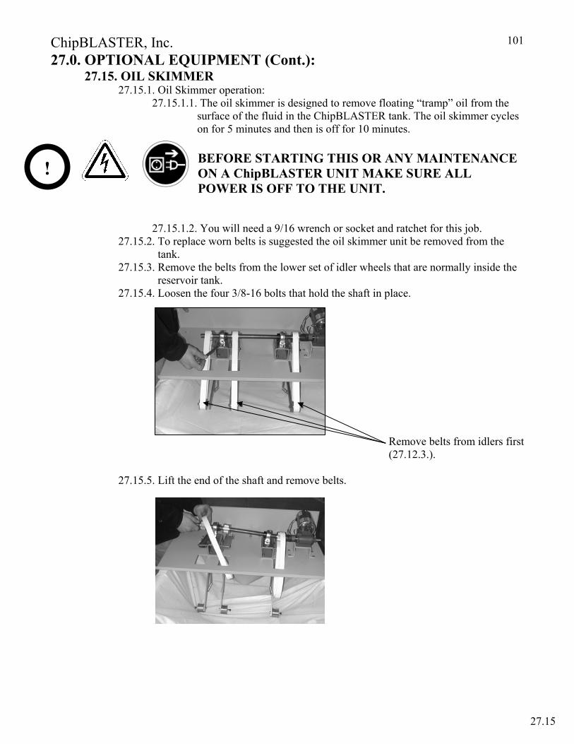
ChipBLASTER, Inc.
101
27.0. OPTIONAL EQUIPMENT (Cont.): 27.15. OIL SKIMMER 27.15.1. Oil Skimmer operation: 27.15.1.1. The oil skimmer is designed to remove floating “tramp” oil from the surface of the fluid in the ChipBLASTER tank. The oil skimmer cycles on for 5 minutes and then is off for 10 minutes.
BEFORE STARTING THIS OR ANY MAINTENANCE ON A ChipBLASTER UNIT MAKE SURE ALL POWER IS OFF TO THE UNIT.
27.15.1.2. You will need a 9/16 wrench or socket and ratchet for this job. 27.15.2. To replace worn belts is suggested the oil skimmer unit be removed from the
tank. 27.15.3. Remove the belts from the lower set of idler wheels that are normally inside the reservoir tank. 27.15.4. Loosen the four 3/8-16 bolts that hold the shaft in place.
Remove belts from idlers first (27.12.3.).
27.15.5. Lift the end of the shaft and remove belts.
!
27.15
ChipBLASTER, Inc.
102
27.0. OPTIONAL EQUIPMENT (Cont.): 27 15. OIL SKIMMER (Cont.)
27.15.6. Inspect the wheels and make sure they are clean and still have grooves to grip the belt.
Note: If the wheels on the shaft are smooth they will not grip the belts! 27.15.7. After you inspect the wheels replace the new belts on the shaft. 27.15.8. Put the bolts back in place and tighten the bolts. 27.15.9. Place the belts back on the wheels in the reservoir tank. 27.15.10. Re-install the oil skimmer unit back on tank. 27.15.11. Plug oil skimmer in and turn power on and inspect when the oil skimmer turns
on. 27.15.12. Close lid and install locking fastener.
DO NOT OPERATE OIL SKIMMER OUTSIDE TANK.
REPLACE ALL PANELS (GUARDS) BEFORE RETURNING THE ChipBLASTER TO PRODUCTION STATUS.
27.15
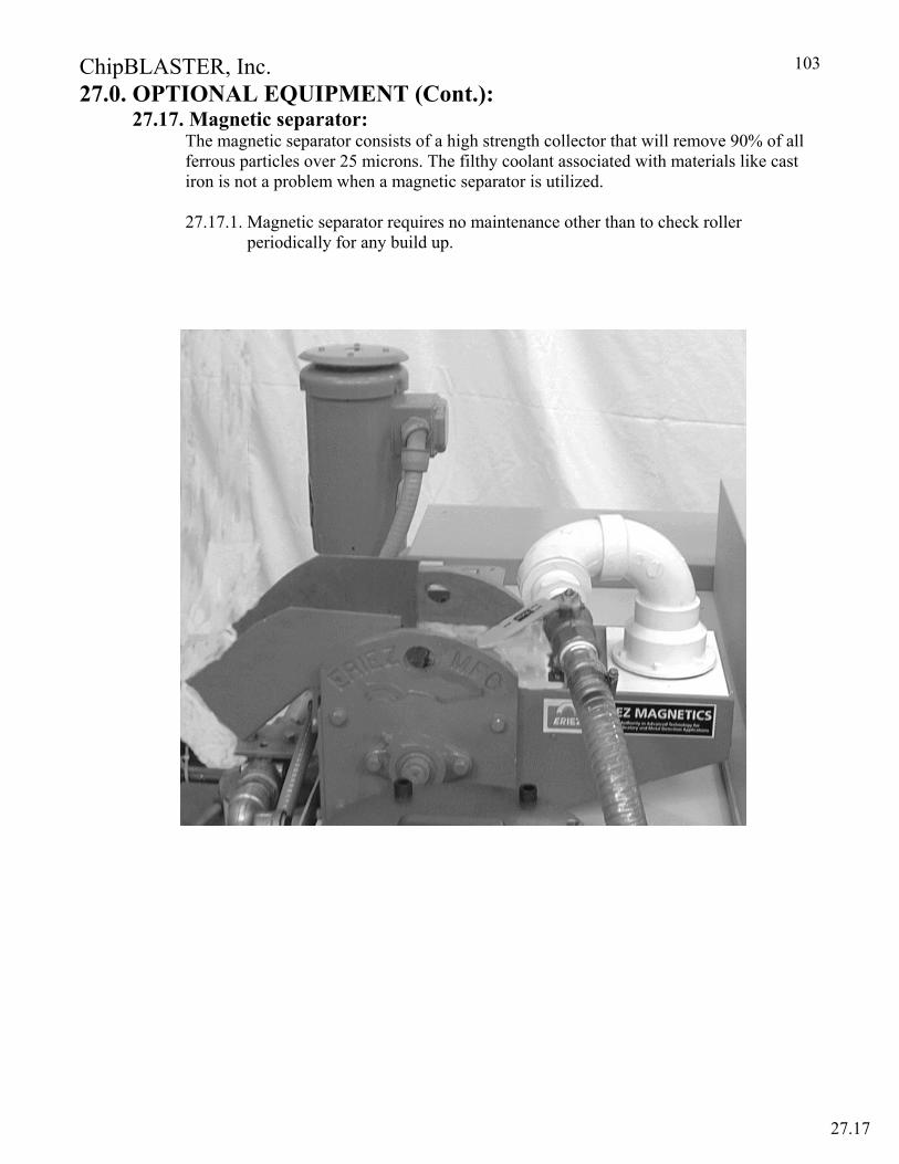
ChipBLASTER, Inc.
103
27.0. OPTIONAL EQUIPMENT (Cont.): 27.17. Magnetic separator: The magnetic separator consists of a high strength collector that will remove 90% of all ferrous particles over 25 microns. The filthy coolant associated with materials like cast iron is not a problem when a magnetic separator is utilized. 27.17.1. Magnetic separator requires no maintenance other than to check roller periodically for any build up.
27.17
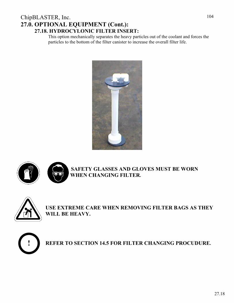
ChipBLASTER, Inc.
104
27.0. OPTIONAL EQUIPMENT (Cont.): 27.18. HYDROCYLONIC FILTER INSERT: This option mechanically separates the heavy particles out of the coolant and forces the particles to the bottom of the filter canister to increase the overall filter life.
SAFETY GLASSES AND GLOVES MUST BE WORN WHEN CHANGING FILTER.
USE EXTREME CARE WHEN REMOVING FILTER BAGS AS THEY WILL BE HEAVY.
REFER TO SECTION 14.5 FOR FILTER CHANGING PROCUDURE.
!
27.18
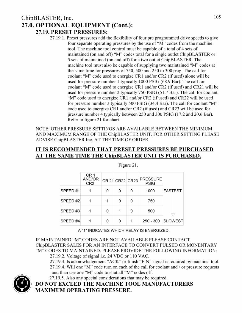
ChipBLASTER, Inc.
105
27.0. OPTIONAL EQUIPMENT (Cont.): 27.19. PRESET PRESSURES: 27.19.1. Preset pressures add the flexibility of four pre programmed drive speeds to give
four separate operating pressures by the use of “M” codes from the machine tool. The machine tool control must be capable of a total of 4 sets of maintained (on and off) “M” codes total for a single outlet ChipBLASTER or 5 sets of maintained (on and off) for a two outlet ChipBLASTER. The machine tool must also be capable of supplying two maintained “M” codes at the same time for pressures of 750, 500 and 250 to 300 psig. The call for coolant “M” code used to energize CR1 and/or CR2 (if used) alone will be used for pressure number 1 typically 1000 PSIG (68.9 Bar). The call for coolant “M” code used to energize CR1 and/or CR2 (if used) and CR21 will be used for pressure number 2 typically 750 PSIG (51.7 Bar). The call for coolant “M” code used to energize CR1 and/or CR2 (if used) and CR22 will be used for pressure number 3 typically 500 PSIG (34.4 Bar). The call for coolant “M” code used to energize CR1 and/or CR2 (if used) and CR23 will be used for pressure number 4 typically between 250 and 300 PSIG (17.2 and 20.6 Bar). Refer to figure 21 for chart.
NOTE: OTHER PRESSURE SETTINGS ARE AVAILABLE BETWEEN THE MINIMUM AND MAXIMUM RANGE OF THE ChipBLASTER UNIT. FOR OTHER SETTING PLEASE ADVISE ChipBLASTER Inc. AT THE TIME OF ORDER.
IT IS RECOMMENDED THAT PRESET PRESSURES BE PURCHASED AT THE SAME TIME THE ChipBLASTER UNIT IS PURCHASED.
Figure 21. IF MAINTAINED “M” CODES ARE NOT AVAILABLE PLEASE CONTACT ChipBLASTER SALES FOR AN INTERFACE TO CONVERT PULSED OR MONENTARY “M” CODES TO MAINTAINED. PLEASE PROVIDE THE FOLLOWING INFORMATION:
27.19.2. Voltage of signal i.e. 24 VDC or 110 VAC. 27.19.3. Is acknowledgement “ACK” or finish “FIN” signal is required by machine tool. 27.19.4. Will one “M” code turn on each of the call for coolant and / or pressure requests and than use one “M” code to shut all “M” codes off. 27.19.5. Also any special considerations that may be required.
DO NOT EXCEED THE MACHINE TOOL MANUFACTURERS MAXIMUM OPERATING PRESSURE.
A "1" INDICATES WHICH RELAY IS ENERGIZED.
CR 1CR23CR22CR 21
500
250 - 3001SPEED #4 0 10
1SPEED #3 1 00
SLOWEST
1000
7501SPEED #2 0 01
1SPEED #1 000 FASTEST
CR2AND/OR PRESSURE
PSIG
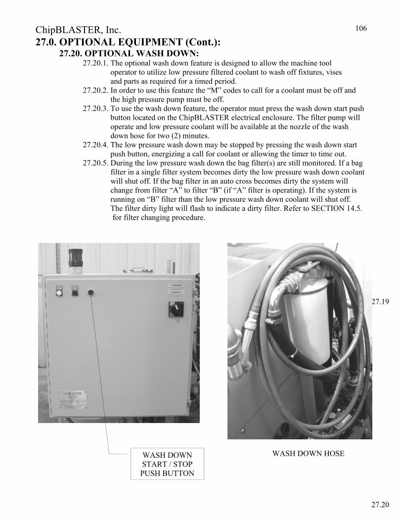
ChipBLASTER, Inc.
106
27.0. OPTIONAL EQUIPMENT (Cont.): 27.20. OPTIONAL WASH DOWN:
27.20.1. The optional wash down feature is designed to allow the machine tool operator to utilize low pressure filtered coolant to wash off fixtures, vises and parts as required for a timed period.
27.20.2. In order to use this feature the “M” codes to call for a coolant must be off and the high pressure pump must be off.
27.20.3. To use the wash down feature, the operator must press the wash down start push button located on the ChipBLASTER electrical enclosure. The filter pump will operate and low pressure coolant will be available at the nozzle of the wash down hose for two (2) minutes.
27.20.4. The low pressure wash down may be stopped by pressing the wash down start push button, energizing a call for coolant or allowing the timer to time out.
27.20.5. During the low pressure wash down the bag filter(s) are still monitored. If a bag filter in a single filter system becomes dirty the low pressure wash down coolant will shut off. If the bag filter in an auto cross becomes dirty the system will change from filter “A” to filter “B” (if “A” filter is operating). If the system is running on “B” filter than the low pressure wash down coolant will shut off. The filter dirty light will flash to indicate a dirty filter. Refer to SECTION 14.5. for filter changing procedure.
WASH DOWN HOSE
27.19
27.20
WASH DOWN START / STOP PUSH BUTTON

ChipBLASTER, Inc.
107
27.0. OPTIONAL EQUIPMENT (Cont.): 27.21. OPTIONAL DROP IN CHILLER:
TURMOIL WEST SWANZEY, NH 03469
603-352-0053
INSTALLATION, MAINTENANCE and OPERATION MANUAL
MODEL OC - 75 DI CTC/ATC
TABLE OF CONTENTS Description Page Uncrating & Inspection Section 27.21.1 120 Cooler Placement Section 27.21.2 120 Electrical Hook-up Section 27.21.3 120
Temperature Controller Section 27.21.4 121 Start-up Section 27.21.5 121 Operation Section 27.21.6 121
Safety Interlocks Section 27.21.7 121 Maintenance Section 27.21.8 121 Trouble Shooting Section 27.21.9 122 Parts List Section 27.21.10 123 ATC/CTC Temperature Controller Setup Section 27.21.11 124 Electrical Schematic Section 27.21.12 127 Dimensional Prints Section 27.21.13 128
27.21
ChipBLASTER, Inc.
108
27.0. OPTIONAL EQUIPMENT (Cont.): 27.21. OPTIONAL DROP IN CHILLER (Cont.):
WARNING DO NOT ATTEMPT TO START UP THIS COOLER UNTIL YOU HAVE READ THROUGH THE
INSTRUCTIONS COMPLETELY. IMPROPER START-UP WILL VOID THE COOLER WARRANTY AND DAMAGE THE MACHINE.
27.21.1. UNCRATING & INSPECTION 27.21.1.1. Rough handling during shipment may cause obvious and / or concealed
damage. Upon arrival, the cooler should be inspected carefully and claims for damage must be filed immediately with the trucker.
27.21.1.2. When uncrating the cooler, inspect it thoroughly for signs of concealed damage. Coolers that have been dropped or shipped on their side may not show external damage. If damages are found, a claim must be filed with the carrier within thirty days of delivery.
27.21.2. COOLER PLACEMENT 27.21.2.1.The cooler is designed to be mounted on top of a tank with the stainless
steel evaporator coils fully immersed. Tank liquid level should be maintained within 8” of the top of the tank. Lower liquid level will reduce the cooling capacity or damage the compressor. The cooler should never be operated without the stainless steel evaporator coils completely immersed in liquid.
27.21.2.2. The cooler is provided with an air intake filter that must be kept clean. The cooler will draw air in through the air filter on the front panel and exhale air through the top. It is imperative that these vents remain open to permit the free movement of air. Lack of adequate cool air will cause a reduction in cooling capacity and/or completely shutdown the refrigeration compressor.
(Two feet of open space on air intake and discharge). 27.21.2.3. The cooler is provided with two lifting eyebolts. Use these two
eyebolts to lift the cooler and place it in position on the sump tank. The cooler cabinet should be securely fastened to the sump top.
27.21.3. ELECTRICAL HOOK-UP 27.21.3.1. See Electrical diagram attached. The cooler is wired for 230 Volt /60 Hertz /1 Phase. Check name plate to verify the proper voltage, hertz
and phase. The supply voltage must be within 10% of the rated voltage on the tag. Make ground connection to the grounding screw provided. Check for loose wires. The power connection should be made to the terminals tagged L1 and L2 on the terminal strip in the junction box on the right side panel.
27.21.3.2. Terminals #10 and #11 are wired to a HIGH TEMPERATURE interlock switch. This switch opens when coolant temperature exceeds a high temperature setting (See attached temperature controller instructions on adjusting this setting).
27.21
ChipBLASTER, Inc.
109
27.0. OPTIONAL EQUIPMENT (Cont.): 27.21. OPTIONAL DROP IN CHILLER (Cont.):
27.21.4. TEMPERATURE CONTROLLER 27.21.4.1. This unit is supplied with a digital temperature controller mounted on the front panel. See the attached instruction sheet for operating this
controller. A selector switch on the front panel tagged ATC/CTC sets the controller to respond as an Ambient Tracking Controller (ATC) or as Set-point Temperature Controller (CTC).
27.21.4.2. The ATC setting works to maintain the coolant at a adjustable temperature differential relative to a fluctuating ambient temperature. The AIR (ambient) sensor is mounted under the temperature controller on the front panel. The coolant sensor is mounted in a dry well close to the evaporator coils. The controller will alternate flashing the ambient temperature and the coolant temperature.
27.21.4.3. The CTC setting works to maintain the coolant temperature within 0.5° F of the adjustable set-point. The controller will alternate flashing the
set point temperature (S) and the actual temperature (F) 27.21.5. START - UP
27.21.5.1. Once the cooler has been installed and the proper electrical connections have been made, it can be started by pressing the ON/OFF switch on
the front panel to the ON position. When the switch is pressed to the ON position, an internal green light will energize and the compressor and fan will start if the controller is calling for cooling (after a one minute delay). Do not operate the cooler if the evaporator coils are not completely submersed in coolant.
27.21.6. OPERATION 27.21.6.1. When the ON/OFF switch is pressed to the ON position, an internal
green light will energize and the compressor and fan will start if the controller is calling for cooling (after a one minute delay). Set the controller to the desired temperature.
27.21.6.2. When the controller calls for cooling, the compressor and condenser fan come on after a one minute delay. Refrigerant is pumped by the compressor through the expansion valve to absorb heat as it evaporates in the evaporator/heat exchanger. When the controller calls for heating, the compressor and fan shut down. The cooler should now be ready for continuous operation.
27.21.7. SAFETY INTERLOCKS 27.21.7.1. HIGH TEMPERATURE INTERLOCK
27.21.7.1.1. This cooler has a HIGH TEMPERATURE interlock warning built into the temperature controller. See ATC/CTC controller
instructions attached. If the coolant temperature exceeds the high temperature setting the cooler will continue to run but contacts across terminals #10 and #11 will open.
27.21.8. MAINTENANCE 27.21.8.1. Every Turmoil cooler is carefully assembled from the finest
components by skilled craftsmen. Each cooler is thoroughly tested and inspected before it leaves the factory. However, in order to obtain efficient service and long life from this cooler, it must be given proper care as with any other piece of mechanical equipment
27.21
ChipBLASTER, Inc.
110
27.0. OPTIONAL EQUIPMENT (Cont.): 27.21. OPTIONAL DROP IN CHILLER (Cont.):
27.21.8.2. AIR FILTER: Keep Clean 27.21.8.3. CONDENSER: Condenser fins should be cleaned of dust and dirt
regularly. 27.21.8.4. PUMP: See attached pump instructions.
27.21.9. TROUBLE SHOOTING PROBLEM CAUSE SOLUTION Cooler operative A. Low Coolant Level Add Coolant but not cooling B. Dirty Air Filter Clean C. Blocked Air Flow Remove Blockage D. Condenser Clogged Clean E. Faulty Controller Repair/Replace F. Low Refrigerant Charge Repair * G. Faulty Compressor Repair/Replace * H. Faulty Solenoid Valve/ Replace * Coil I. Incorrect Expansion Adjust Expansion Valve to proper setting * Valve setting Cooler inoperative A. Faulty Power Source Check & Correct or does not start B. Cooler OFF on Low Check for: Pressure Low Coolant Level No Coolant Flow across the coils Low Ambient Wrong Setting on Pressure Switch Low or Lost Refrigerant Charge * Incorrect Expansion Valve Setting * • Actions designated with * should only be done by a Qualified Refrigeration Service Person. check with factory for proper settings.
27.21
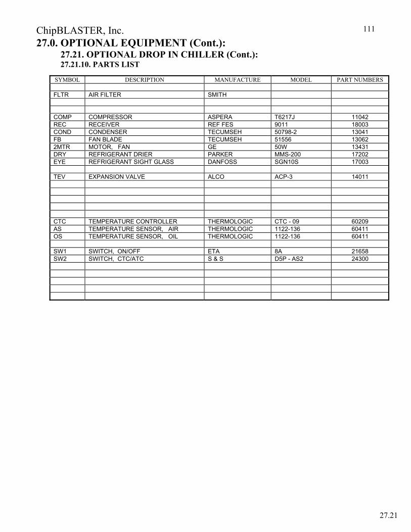
ChipBLASTER, Inc.
111
27.0. OPTIONAL EQUIPMENT (Cont.): 27.21. OPTIONAL DROP IN CHILLER (Cont.):
27.21.10. PARTS LIST
SYMBOL DESCRIPTION MANUFACTURE MODEL PART NUMBERS FLTR AIR FILTER SMITH COMP COMPRESSOR ASPERA T6217J 11042 REC RECEIVER REF FES 9011 18003 COND CONDENSER TECUMSEH 50798-2 13041 FB FAN BLADE TECUMSEH 51556 13062 2MTR MOTOR, FAN GE 50W 13431 DRY REFRIGERANT DRIER PARKER MMS-200 17202 EYE REFRIGERANT SIGHT GLASS DANFOSS SGN10S 17003 TEV EXPANSION VALVE ALCO ACP-3 14011 CTC TEMPERATURE CONTROLLER THERMOLOGIC CTC - 09 60209 AS TEMPERATURE SENSOR, AIR THERMOLOGIC 1122-136 60411 OS TEMPERATURE SENSOR, OIL THERMOLOGIC 1122-136 60411 SW1 SWITCH, ON/OFF ETA 8A 21658 SW2 SWITCH, CTC/ATC S & S D5P - AS2 24300
27.21
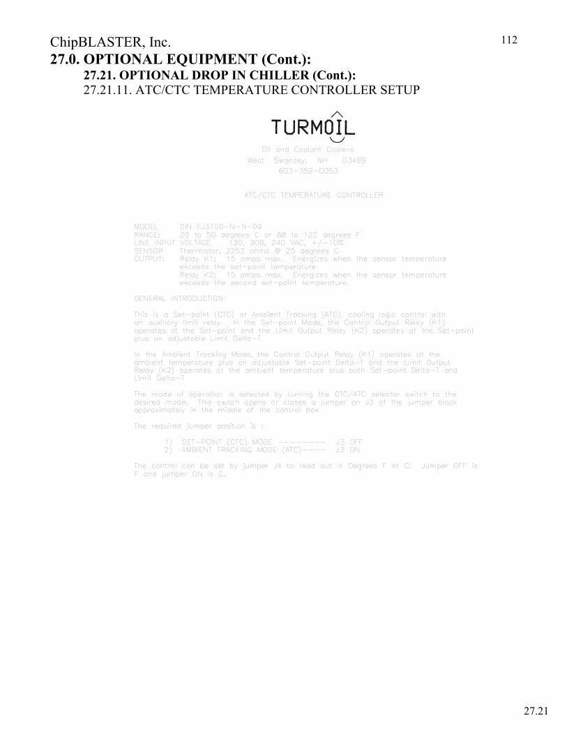
ChipBLASTER, Inc.
112
27.0. OPTIONAL EQUIPMENT (Cont.): 27.21. OPTIONAL DROP IN CHILLER (Cont.):
27.21.11. ATC/CTC TEMPERATURE CONTROLLER SETUP
27.21
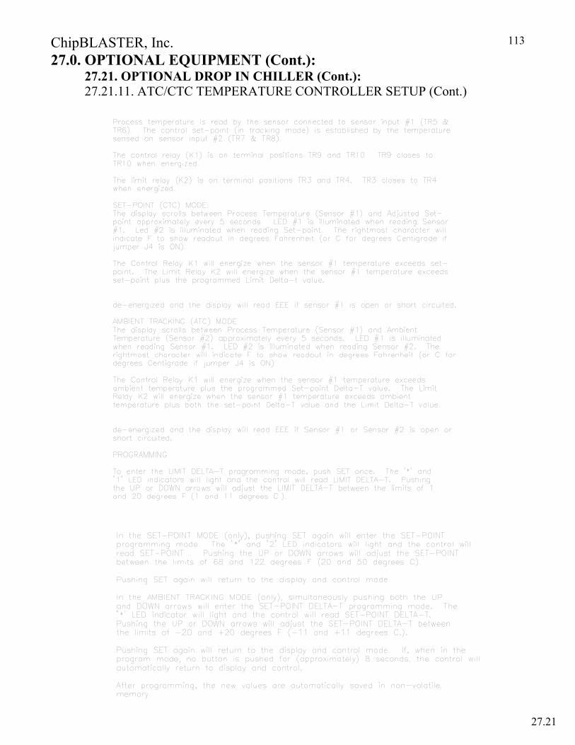
ChipBLASTER, Inc.
113
27.0. OPTIONAL EQUIPMENT (Cont.): 27.21. OPTIONAL DROP IN CHILLER (Cont.):
27.21.11. ATC/CTC TEMPERATURE CONTROLLER SETUP (Cont.)
27.21
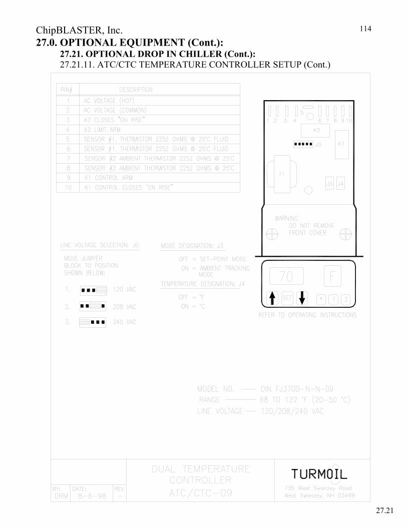
ChipBLASTER, Inc.
114
27.0. OPTIONAL EQUIPMENT (Cont.): 27.21. OPTIONAL DROP IN CHILLER (Cont.):
27.21.11. ATC/CTC TEMPERATURE CONTROLLER SETUP (Cont.)
27.21
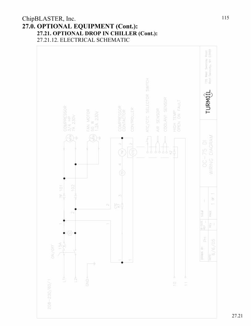
ChipBLASTER, Inc.
115
27.0. OPTIONAL EQUIPMENT (Cont.): 27.21. OPTIONAL DROP IN CHILLER (Cont.): 27.21.12. ELECTRICAL SCHEMATIC
27.21
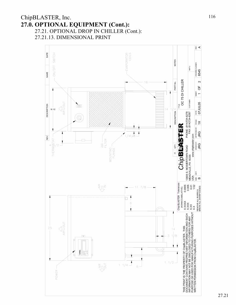
ChipBLASTER, Inc.
116
27.0. OPTIONAL EQUIPMENT (Cont.): 27.21. OPTIONAL DROP IN CHILLER (Cont.):
27.21.13. DIMENSIONAL PRINT
OC
75
DI C
HIL
LER
JRG
JRG
07JU
L05
8545
12
A1X
16 1/2
27.21
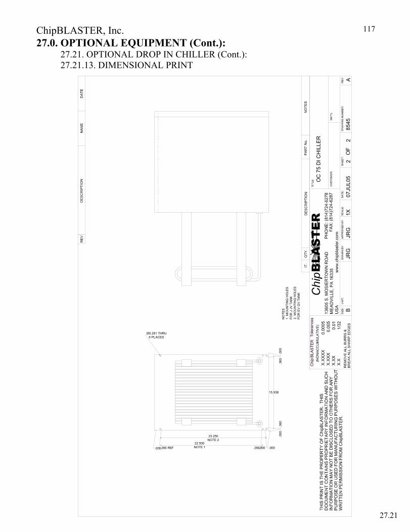
ChipBLASTER, Inc.
117
27.0. OPTIONAL EQUIPMENT (Cont.): 27.21. OPTIONAL DROP IN CHILLER (Cont.): 27.21.13. DIMENSIONAL PRINT
27.21
OC
75
DI C
HIL
LER
JRG
JRG
07JU
L05
8545
22
A1X
.266 REF
23.250NOTE 2
.000
.000.266.266 22.500NOTE 1
NO
TES
1. M
OU
NTI
NG
HO
LES
FOR
J J
V TA
NK
2. M
OU
NTI
NG
HO
LES
FOR
EV
GV
TAN
K
.360
.360
.000
15.938
.000
Ø0.281 THRU6 PLACES
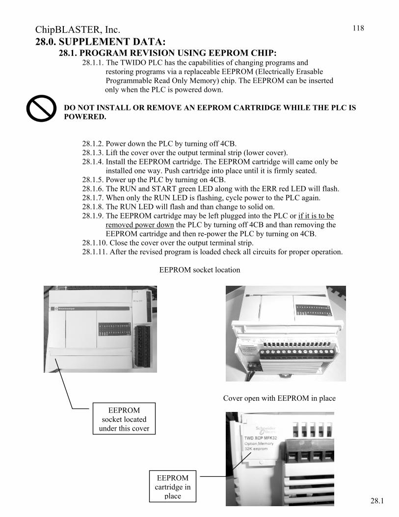
ChipBLASTER, Inc.
118
28.0. SUPPLEMENT DATA: 28.1. PROGRAM REVISION USING EEPROM CHIP:
28.1.1. The TWIDO PLC has the capabilities of changing programs and restoring programs via a replaceable EEPROM (Electrically Erasable
Programmable Read Only Memory) chip. The EEPROM can be inserted only when the PLC is powered down. DO NOT INSTALL OR REMOVE AN EEPROM CARTRIDGE WHILE THE PLC IS POWERED.
28.1.2. Power down the PLC by turning off 4CB. 28.1.3. Lift the cover over the output terminal strip (lower cover). 28.1.4. Install the EEPROM cartridge. The EEPROM cartridge will came only be
installed one way. Push cartridge into place until it is firmly seated. 28.1.5. Power up the PLC by turning on 4CB. 28.1.6. The RUN and START green LED along with the ERR red LED will flash. 28.1.7. When only the RUN LED is flashing, cycle power to the PLC again. 28.1.8. The RUN LED will flash and than change to solid on. 28.1.9. The EEPROM cartridge may be left plugged into the PLC or if it is to be
removed power down the PLC by turning off 4CB and than removing the EEPROM cartridge and then re-power the PLC by turning on 4CB.
28.1.10. Close the cover over the output terminal strip. 28.1.11. After the revised program is loaded check all circuits for proper operation.
EEPROM socket location
Cover open with EEPROM in place
EEPROM socket located
under this cover
EEPROM cartridge in
place 28.1

ChipBLASTER, Inc.
119
28.0. SUPPLEMENT DATA (CONT.): 28.2. Orifice Reference Chart for 1000 PSI
Orifice Dia. Outlet Area (Sq. Inches)
PSI Velocity (Ft./Sec.) Volume (GPM)
Horsepower Required
Machine maximum outputs
0.010 0.0001 1000 465 0.1 0.1 0.015 0.0002 1000 465 0.3 0.2 0.020 0.0003 1000 465 0.5 0.3 0.025 0.0005 1000 465 0.7 0.5 0.030 0.0007 1000 465 1.0 0.7
0.035 0.0010 1000 465 1.4 1.0
0.040 0.0013 1000 465 1.8 1.2 0.045 0.0016 1000 465 2.3 1.6 0.050 0.0020 1000 465 2.8 1.9 0.055 0.0024 1000 465 3.4 2.4
Nozzle #XX54 0.0024 1000 465 3.6 2.4 0.060 0.0028 1000 465 4.1 2.8
Nozzle #XX55 0.0028 1000 465 4.1 2.8 J4 - 1000 0.065 0.0033 1000 465 4.8 3.3 0.070 0.0038 1000 465 5.6 3.8 0.075 0.0044 1000 465 6.4 4.4
Nozzle #XX56 0.0049 1000 465 7.1 4.9 0.080 0.0050 1000 465 7.8 5.1 J8 - 1000 0.085 0.0057 1000 465 8.2 5.6 JV8 - 1000 0.090 0.0064 1000 465 9.2 6.3
Nozzle #XX57 0.0069 1000 465 10.0 6.8 0.095 0.0071 1000 465 10.3 7.0 0.100 0.0079 1000 465 11.4 7.8 0.105 0.0087 465 12.5 8.6 0.110 0.0095 1000 465 13.8 9.4 EV2000 0.115 0.0104 1000 465 15.0 10.3 0.120 0.0113 1000 465 16.4 11.2 CV16 0.125 0.0123 1000 465 17.8 12.2 0.130 0.0133 1000 465 19.2 13.2
Nozzle #XX58 0.0138 1000 465 20.0 13.7 0.135 0.0143 1000 465 20.7 14.2 0.140 0.0154 1000 465 22.3 15.3 0.145 0.0165 1000 465 23.9 16.4 0.150 0.0177 1000 465 25.6 17.5 CV26 0.155 0.0189 1000 465 27.3 18.7 0.160 0.0201 1000 465 29.1 19.9 0.165 0.0214 1000 465 31.0 21.2 0.170 0.0227 1000 465 32.9 22.5 0.175 0.0241 1000 465 34.8 23.9 0.180 0.0254 1000 465 36.9 25.2 CV36 0.185 0.0269 1000 465 38.9 26.7 0.190 0.0284 1000 465 41.1 28.1 0.195 0.0299 1000 465 43.3 29.6 0.200 0.0314 1000 465 45.5 31.2 0.205 0.0330 1000 465 47.8 32.7 0.210 0.0346 1000 465 50.2 34.4 0.215 0.0363 1000 465 52.6 36.0 0.220 0.0380 1000 465 55.1 37.7 0.245 0.0471 1000 465 68.3 46.8 0.250 0.0491 1000 465 71.1 48.7 0.255 0.0511 1000 465 74.0 50.7 0.265 0.0552 1000 465 79.9 54.7 MV-1000
28.2
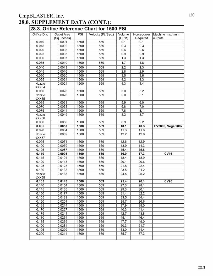
ChipBLASTER, Inc.
120
28.0. SUPPLEMENT DATA (CONT.): 28.3. Orifice Reference Chart for 1500 PSI
Orifice Dia. Outlet Area (Sq. Inches)
PSI Velocity (Ft./Sec.) Volume (GPM)
Horsepower Required
Machine maximum outputs
0.010 0.0001 1500 569 0.1 0.1 0.015 0.0002 1500 569 0.3 0.3 0.020 0.0003 1500 569 0.6 0.6 0.025 0.0005 1500 569 0.9 0.9 0.030 0.0007 1500 569 1.3 1.3 0.035 0.0010 1500 569 1.7 1.8 0.040 0.0013 1500 569 2.2 2.3 0.045 0.0016 1500 569 2.8 2.9 0.050 0.0020 1500 569 3.5 3.6 0.055 0.0024 1500 569 4.2 4.3 Nozzle #XX54
0.0024 1500 569 4.3 4.4
0.060 0.0028 1500 569 5.0 5.2 Nozzle #XX55
0.0028 1500 569 5.0 5.1
0.065 0.0033 1500 569 5.9 6.0 0.070 0.0038 1500 569 6.8 7.0 0.075 0.0044 1500 569 7.8 8.1 Nozzle #XX56
0.0049 1500 569 8.3 8.7
0.080 0.0050 1500 569 8.9 9.2 0.085 0.0057 1500 569 10.1 10.3 EV2000, Vega 20020.090 0.0064 1500 569 11.3 11.6 Nozzle #XX57
0.0069 1500 569 12.2 12.6
0.095 0.0071 1500 569 12.6 12.9 0.100 0.0079 1500 569 13.9 14.3 0.105 0.0087 1500 569 15.4 15.8 0.110 0.0095 1500 569 16.9 17.3 CV160.115 0.0104 1500 569 18.4 18.9 0.120 0.0113 1500 569 20.1 20.6 0.125 0.0123 1500 569 21.8 22.4 0.130 0.0133 1500 569 23.5 24.2 Nozzle #XX58
0.0138 1500 569 24.5 25.2
0.135 0.0143 1500 569 25.4 26.1 CV260.140 0.0154 1500 569 27.3 28.1 0.145 0.0165 1500 569 29.3 30.1 0.150 0.0177 1500 569 31.4 32.2 0.155 0.0189 1500 569 33.5 34.4 0.160 0.0201 1500 569 35.7 36.6 0.165 0.0214 1500 569 37.9 39.0 0.170 0.0227 1500 569 40.3 41.4 0.175 0.0241 1500 569 42.7 43.8 0.180 0.0254 1500 569 45.1 46.4 0.185 0.0269 1500 569 47.7 49.0 0.190 0.0284 1500 569 50.3 51.7 0.195 0.0299 1500 569 53.0 54.4 0.200 0.0314 1500 569 55.7 57.3
28.3

ChipBLASTER, Inc.
121
28.0. SUPPLEMENT DATA (CONT.): 28.4. Orifice Reference Chart for 2000 PSI
Orifice Dia. Outlet Area (Sq.
Inches)
PSI Velocity (Ft./Sec.)
Volume (GPM)
Horsepower Required
Machine maximum outputs
0.010 0.0001 2000 657 0.2 0.2 0.015 0.0002 2000 657 0.4 0.5 0.020 0.0003 2000 657 0.6 0.9 0.025 0.0005 2000 657 1.0 1.4 0.030 0.0007 2000 657 1.4 2.0 0.035 0.0010 2000 657 2.0 2.7 0.040 0.0013 2000 657 2.6 3.5 0.045 0.0016 2000 657 3.3 4.5 0.050 0.0020 2000 657 4.0 5.5 0.055 0.0024 2000 657 4.9 6.7
Nozzle #XX54 0.0024 2000 657 5.0 6.8 0.060 0.0028 2000 657 5.8 7.9
Nozzle #XX55 0.0028 2000 657 5.7 7.9 0.065 0.0033 2000 657 6.8 9.3 0.070 0.0038 2000 657 7.9 10.8 EV2000, Vega 20020.075 0.0044 2000 657 9.1 12.4
Nozzle #XX56 0.0049 2000 657 10.0 13.7 0.080 0.0050 2000 657 10.3 14.1 0.085 0.0057 2000 657 11.6 15.9 0.090 0.0064 2000 657 13.0 17.9
Nozzle #XX57 0.0069 2000 657 14.1 19.4 0.095 0.0071 2000 657 14.5 19.9 0.100 0.0079 2000 657 16.1 22.0 CV160.105 0.0087 2000 657 17.7 24.3 0.110 0.0095 2000 657 19.5 26.7 0.115 0.0104 2000 657 21.3 29.1 CV260.120 0.0113 2000 657 23.2 31.7 0.125 0.0123 2000 657 25.1 34.4 0.130 0.0133 2000 657 27.2 37.2
Nozzle #XX58 0.0138 2000 657 28.3 38.7 0.135 0.0143 2000 657 29.3 40.2 0.140 0.0154 2000 657 31.5 43.2 0.145 0.0165 2000 657 33.8 46.3 0.150 0.0177 2000 657 36.2 49.6 0.155 0.0189 2000 657 38.7 53.0 0.160 0.0201 2000 657 41.2 56.4 0.165 0.0214 2000 657 43.8 60.0 0.170 0.0227 2000 657 46.5 63.7 0.175 0.0241 2000 657 49.3 67.5 0.180 0.0254 2000 657 52.1 71.4 0.185 0.0269 2000 657 55.1 75.4 0.190 0.0284 2000 657 58.1 79.6 0.195 0.0299 2000 657 61.2 83.8 0.200 0.0314 2000 657 64.4 88.2
28.4
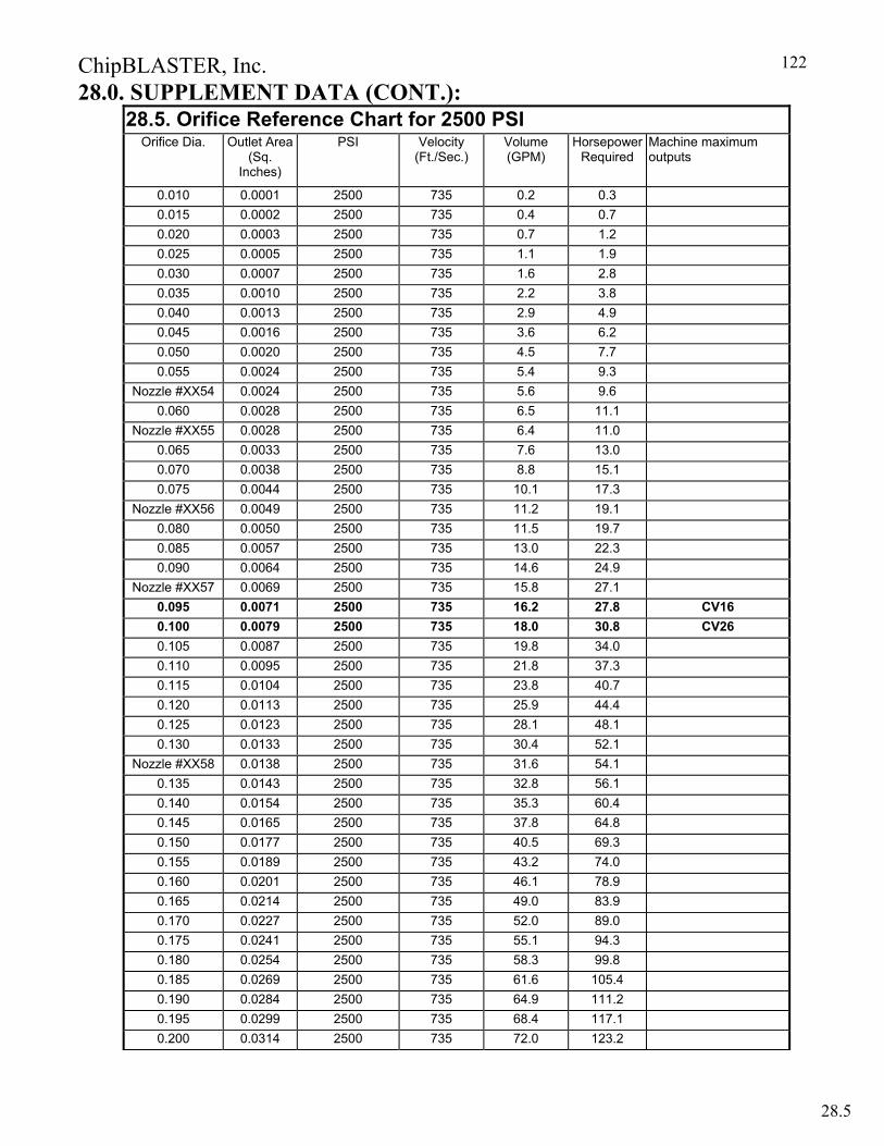
ChipBLASTER, Inc.
122
28.0. SUPPLEMENT DATA (CONT.): 28.5. Orifice Reference Chart for 2500 PSI
Orifice Dia. Outlet Area (Sq.
Inches)
PSI Velocity (Ft./Sec.)
Volume (GPM)
Horsepower Required
Machine maximum outputs
0.010 0.0001 2500 735 0.2 0.3 0.015 0.0002 2500 735 0.4 0.7 0.020 0.0003 2500 735 0.7 1.2 0.025 0.0005 2500 735 1.1 1.9 0.030 0.0007 2500 735 1.6 2.8 0.035 0.0010 2500 735 2.2 3.8 0.040 0.0013 2500 735 2.9 4.9 0.045 0.0016 2500 735 3.6 6.2 0.050 0.0020 2500 735 4.5 7.7 0.055 0.0024 2500 735 5.4 9.3
Nozzle #XX54 0.0024 2500 735 5.6 9.6 0.060 0.0028 2500 735 6.5 11.1
Nozzle #XX55 0.0028 2500 735 6.4 11.0 0.065 0.0033 2500 735 7.6 13.0 0.070 0.0038 2500 735 8.8 15.1 0.075 0.0044 2500 735 10.1 17.3
Nozzle #XX56 0.0049 2500 735 11.2 19.1 0.080 0.0050 2500 735 11.5 19.7 0.085 0.0057 2500 735 13.0 22.3 0.090 0.0064 2500 735 14.6 24.9
Nozzle #XX57 0.0069 2500 735 15.8 27.1 0.095 0.0071 2500 735 16.2 27.8 CV160.100 0.0079 2500 735 18.0 30.8 CV260.105 0.0087 2500 735 19.8 34.0 0.110 0.0095 2500 735 21.8 37.3 0.115 0.0104 2500 735 23.8 40.7 0.120 0.0113 2500 735 25.9 44.4 0.125 0.0123 2500 735 28.1 48.1 0.130 0.0133 2500 735 30.4 52.1
Nozzle #XX58 0.0138 2500 735 31.6 54.1 0.135 0.0143 2500 735 32.8 56.1 0.140 0.0154 2500 735 35.3 60.4 0.145 0.0165 2500 735 37.8 64.8 0.150 0.0177 2500 735 40.5 69.3 0.155 0.0189 2500 735 43.2 74.0 0.160 0.0201 2500 735 46.1 78.9 0.165 0.0214 2500 735 49.0 83.9 0.170 0.0227 2500 735 52.0 89.0 0.175 0.0241 2500 735 55.1 94.3 0.180 0.0254 2500 735 58.3 99.8 0.185 0.0269 2500 735 61.6 105.4 0.190 0.0284 2500 735 64.9 111.2 0.195 0.0299 2500 735 68.4 117.1 0.200 0.0314 2500 735 72.0 123.2
28.5
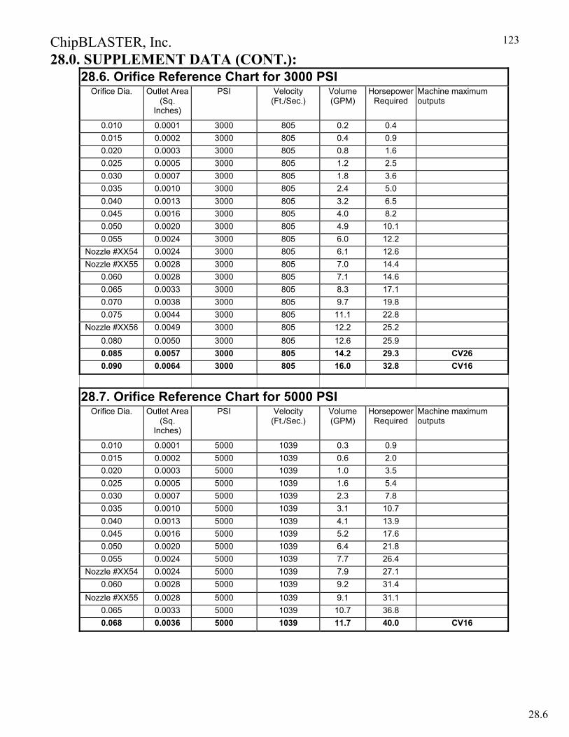
ChipBLASTER, Inc.
123
28.0. SUPPLEMENT DATA (CONT.): 28.6. Orifice Reference Chart for 3000 PSI
Orifice Dia. Outlet Area (Sq.
Inches)
PSI Velocity (Ft./Sec.)
Volume (GPM)
Horsepower Required
Machine maximum outputs
0.010 0.0001 3000 805 0.2 0.4 0.015 0.0002 3000 805 0.4 0.9 0.020 0.0003 3000 805 0.8 1.6 0.025 0.0005 3000 805 1.2 2.5 0.030 0.0007 3000 805 1.8 3.6 0.035 0.0010 3000 805 2.4 5.0 0.040 0.0013 3000 805 3.2 6.5 0.045 0.0016 3000 805 4.0 8.2 0.050 0.0020 3000 805 4.9 10.1 0.055 0.0024 3000 805 6.0 12.2
Nozzle #XX54 0.0024 3000 805 6.1 12.6 Nozzle #XX55 0.0028 3000 805 7.0 14.4
0.060 0.0028 3000 805 7.1 14.6 0.065 0.0033 3000 805 8.3 17.1 0.070 0.0038 3000 805 9.7 19.8 0.075 0.0044 3000 805 11.1 22.8
Nozzle #XX56 0.0049 3000 805 12.2 25.2 0.080 0.0050 3000 805 12.6 25.9 0.085 0.0057 3000 805 14.2 29.3 CV260.090 0.0064 3000 805 16.0 32.8 CV16
28.7. Orifice Reference Chart for 5000 PSI Orifice Dia. Outlet Area
(Sq. Inches)
PSI Velocity (Ft./Sec.)
Volume (GPM)
Horsepower Required
Machine maximum outputs
0.010 0.0001 5000 1039 0.3 0.9 0.015 0.0002 5000 1039 0.6 2.0 0.020 0.0003 5000 1039 1.0 3.5 0.025 0.0005 5000 1039 1.6 5.4 0.030 0.0007 5000 1039 2.3 7.8 0.035 0.0010 5000 1039 3.1 10.7 0.040 0.0013 5000 1039 4.1 13.9 0.045 0.0016 5000 1039 5.2 17.6 0.050 0.0020 5000 1039 6.4 21.8 0.055 0.0024 5000 1039 7.7 26.4
Nozzle #XX54 0.0024 5000 1039 7.9 27.1 0.060 0.0028 5000 1039 9.2 31.4
Nozzle #XX55 0.0028 5000 1039 9.1 31.1 0.065 0.0033 5000 1039 10.7 36.8 0.068 0.0036 5000 1039 11.7 40.0 CV16
28.6