european energy storage technology development … · draft – for public consultation joint...
TRANSCRIPT
DRAFT – FOR PUBLIC CONSULTATION
Joint EASE-EERA Recommendations for a
EUROPEAN ENERGY STORAGE TECHNOLOGY
DEVELOPMENT ROADMAP TOWARDS 2030 –
UPDATE

DRAFT – FOR PUBLIC CONSULTATION
2
EASE/EERA European Energy Storage Technology Development Roadmap
The European Association for Storage of
Energy (EASE) is the voice of the energy
storage community, actively promoting the
use of energy storage in Europe and
worldwide. Since its establishment in 2011,
EASE has supported the deployment of
energy storage as an indispensable
instrument to support Europe’s ambitious
clean energy and climate policies. EASE’s
members come from all sectors of the
energy storage value chain who are
committed to supporting the transition
towards a sustainable, flexible, and stable
energy system in Europe.
For further information, please visit
www.ease-storage.eu.
EERA, the European Energy Research
Alliance, is an alliance of leading
organisations in the field of energy
research. EERA aims to strengthen, expand,
and optimise EU energy research
capabilities through the sharing of world-
class national facilities in Europe and the
joint realisation of pan-European research
programmes (EERA Joint Programmes). The
primary focus of EERA is to accelerate the
development of energy technologies to the
point where they can be embedded in
industry-driven research. In order to
achieve this goal, EERA streamlines and
coordinates national and European energy
R&D programmes.
For further information, please visit www.eera-set.eu.
DRAFT – FOR PUBLIC CONSULTATION
3
EASE/EERA European Energy Storage Technology Development Roadmap
Acknowledgments
EASE and EERA would like to extend a warm thank you to the contributors to this
Roadmap, without whom this effort would not have been possible. EASE and EERA
also thank their members for their valuable support.
Contributing authors: Myriam Elisa Gil Bardajií (KIT; EERA JP Energy Storage); Dan
Bauer (DLR); Thomas Bauer (DLR); Brittney Becker (EASE); Laurent Bedel (CEA);
Christian Bergins (MHPSE); Robert Bubeck (Bosch); Torsten Buddenberg (MHPSE); Mark
Byrne (Gaelectric); Patrick Clerens (EASE), Giorgio Crugnola (FIAMM); Giovanna
Cavazzini (U Padova); Mario Conte (ENEA); Yulong Ding (U Birmingham); Raymond
Dorney (Gaelectric); Jean-Michel Durand (EASE); Jan Ernst (Maxwell Technologies);
Maximilian Fichtner (KIT HIU); Edouard de Frescheville (GE); Victoria Gerus (EASE);
Duncan Gibb (DLR); Adelbert Goede (DIFFER); Fedor Gömöry (IEE SAS); Xavier
Granados (CSIC); Peter Hall (U Sheffield); Atle Harby (SINTEF); Joris Koornneef (TNO);
Marcos Lafoz (CIEMAT); Michael Lippert (Saft); Marc Linder (DLR); Cristina Luengo (CIC
Energigune); Francesco Lufrano (CNR); Rowena McCappin (GlenDimplex); Kim
McGrath (Maxwell Technologies); Fernando Morales (Highview Power); Lionel Nadau
(ENGIE); Mathias Noe (KIT; EERA JP Energy Storage); Jesús Palma (IMDEA); Xiaodong
Peng (U Birmingham); Joao Murta Pina (FCT UNL); Allan Schrøder Pedersen (DTU);
Adriano Sciacovelli (U Birmingham); Edel Sheridan (SINTEF); Denis Thomas
(Hydrogenics); Andrea Vecchi (U Birmingham); Jihong Wang (U Warwick); Antje
Wörner (DLR); Stefan Zunft, DLR
Editor: Michela Bortolotti (EASE)
We thank the following stakeholders for their comments and support: Emilie Bekaert
(CIC Energigune); Silvia Bodoardo (POLITO); Marine Delhommeau (EASE); Abdessamak
Faik (CIC Energigune); Eider Goikolea (CIC Energigune); Olivier Guillon (FZJ); Martin
Kirkengen (IFE); Andreas Küppers (GFZ); Oscar Miguel (IK4 CIDETEC); Javier Rodriguez
(CIC Energigune); Ruben Duran (Cobra Energía); Pieter Vanysek (Brno); Carlos Ziebert
(KIT).
DRAFT – FOR PUBLIC CONSULTATION
4
EASE/EERA European Energy Storage Technology Development Roadmap
Table of Contents 1. Summary .......................................................................................................... 6
2. Methodology and Overview ............................................................................... 8
3. Mission and Objectives of the Roadmap .......................................................... 10
4. European and Global Policy as a Driver for Energy Storage Demand ................ 11
4.1 The Policy Framework ............................................................................... 11
4.2 Perspectives for the Future Energy System in Europe ................................ 13
4.3 Role of Energy Storage.............................................................................. 13
4.4 Industrial opportunities for European Energy Storage ............................... 14
4.5 Conclusions .............................................................................................. 15
5. The Need for Energy Storage, Applications, and Potentials in Europe .............. 16
5.1 The Need for Energy Storage .................................................................... 16
5.2 Energy Storage Applications – Electricity Sector ........................................ 17
5.3 Energy Storage Applications – Sector Coupling ......................................... 23
5.4 Introduction to Energy Storage Technologies ............................................ 23
5.5 European Competences in Energy Storage ................................................ 25
6. Energy Storage Technologies .......................................................................... 33
6.1 Chemical Energy Storage .......................................................................... 33
6.2 Electrochemical Energy Storage ................................................................ 40
6.3 Electrical Energy Storage ........................................................................... 51
Supercapacitors .............................................................................................. 51
Superconducting Magnetic Energy Storage (SMES) ........................................... 56
6.4 Mechanical Energy Storage ....................................................................... 63
Compressed Air Energy Storage ...................................................................... 63
Flywheel Energy Storage ................................................................................. 69
Liquid Air Energy Storage ................................................................................ 73
Pumped Hydro Storage ................................................................................... 79
6.5 Thermal Energy Storage ............................................................................ 86
Sensible Heat Storage ..................................................................................... 87
Latent Heat Storage ........................................................................................ 94
Thermochemical Heat Storage......................................................................... 98

DRAFT – FOR PUBLIC CONSULTATION
5
EASE/EERA European Energy Storage Technology Development Roadmap
7. Market Design and Policy Recommendations ................................................. 103
7.1 Policy Recommendations ........................................................................ 103
7.2 Conclusions ............................................................................................ 106
8. Recommendations and Proposed Timeline for Activities ................................ 108
8.1 Identification of Energy Storage R&D Priorities ........................................ 108
8.2 Recommendations and Timeline ............................................................. 109
DRAFT – FOR PUBLIC CONSULTATION
6
EASE/EERA European Energy Storage Technology Development Roadmap
1. Summary The first joint EASE/EERA technology development roadmap on energy storage1 was
published in 2013 with the goal of identifying the most pressing technology
development priorities for the European energy storage industry. Given the many
technological developments in the energy storage sector – and, indeed, the energy
sector as a whole – over the past several years, EASE and EERA have joined forces
once more to draft a significant update to the 2013 roadmap.
The roadmap is a joint effort between the European Association for Storage of Energy
(EASE) and the Joint Programme on Energy Storage (JP ES) under the European Energy
Research Alliance (EERA). The bulk of the work was completed between July and
December 2016 by a core working group composed of EASE and EERA members, with
coordination and support from the EASE and EERA JP ES secretariats. Together, EASE
and EERA members provide a strong foundation of industrial and research expertise,
which allows for a deep and multifaceted insight into the European energy storage
sector.
This updated roadmap provides a comprehensive overview of the energy storage
technologies being developed in Europe today, with a stronger focus on applications,
and identifies the RD&D needs for energy storage in the coming decades. On this
basis, the roadmap provides recommendations for R&D policies and regulatory
changes needed to support the development and large-scale deployment of energy
storage technologies. The aim is to inform policymaking for research, innovation, and
demonstration in the energy storage sector in order to further strengthen Europe’s
research and industrial competitiveness in the energy storage industry.
More information about the methodology used to elaborate this roadmap is contained
in chapter 2. Chapter 3 lists the mission and objectives of this effort. Chapter 4
explains the European and global policy developments affecting the energy system
in Europe and the role foreseen for energy storage. Chapter 5 describes the future
needs for energy storage, explains the key energy storage applications for the
electrical system and for sector coupling, provides an overview of the energy storage
technologies, and outlines the European competences in energy storage.
EASE and EERA consider that a wide range of energy storage technologies will be
needed to address the challenges of the energy transition. Chapter 6, the bulk of this
roadmap, therefore covers the five families of energy storage technologies in detail:
chemical energy storage, electrochemical energy storage, electrical energy storage
(including both supercapacitors and superconducting magnetic energy storage),
mechanical energy storage (covering compressed air energy storage, flywheels, liquid
1 EASE/EERA European Energy Storage Technology Development Roadmap, 2013. http://ease-
storage.eu/wp-content/uploads/2015/10/EASE-EERA-recommendations-Roadmap-LR.pdf
DRAFT – FOR PUBLIC CONSULTATION
7
EASE/EERA European Energy Storage Technology Development Roadmap
air energy storage, and pumped hydro storage), and thermal energy storage (broken
down into sensible heat storage, latent heat storage, and thermochemical heat
storage). For each of these technologies, there is a description of its technical
maturity, applications, R&D targets, an identification of gaps between the present
status and these targets, a list of research priorities, and recommendations for
research funding, infrastructures, and incentives.
Chapter 7 provides market design and policy recommendations aimed at reducing
the barriers to energy storage deployment in Europe. This is important since
ambitious R&D policy and funding alone will not be enough to achieve the energy
storage capacity needed to support the EU’s decarbonisation goals.
In chapter 8, we summarise the R&D priorities we consider most pressing for the
industry as a whole. We situate these along a rough timeline, based on an assessment
of the most immediate needs and of which efforts are likely to yield the most
promising returns for the energy system.

DRAFT – FOR PUBLIC CONSULTATION
8
EASE/EERA European Energy Storage Technology Development Roadmap
2. Methodology and Overview
The first joint EASE/EERA technology development roadmap on energy storage2 (ES)
was published in 2013 with the goal of describing Europe’s future needs for energy
storage (by 2020-2030). The roadmap also contained recommendations on which
technological developments would be required to meet those needs.
Since 2013, there have been significant developments in energy storage
technologies, such as the installation of the world’s largest Liquid Air Energy Storage
(LAES) demonstration plant in the UK3, the construction of Europe’s first hybrid
flywheel plant in Ireland4, and the rapidly declining costs of batteries5 to name a few.
Moreover, there have been significant changes in the market and regulatory
framework. In response to these important developments, an update of the roadmap
and recommendations was needed to adjust and redefine long-term storage targets
(with a timeframe of 2030-2050 in mind).
The vast majority of reports describing future scenarios of the European energy
landscape agree that energy storage will be one of the main tools to support the
energy transition. They are often supported by quantitative modelling work assessing
the generation profile of a society powered (almost) entirely by renewable energy
sources (RES). The quantitative analyses unambiguously point to a significant future
need for energy storage capacity in Europe, the size of which will naturally depend
on many aspects of the energy system such as penetration of RES, electricity
transmission capacity across Europe, penetration of demand-side management and
alternative back-up power availability (e.g. biomass or acceptance of limited use of
fossils in short time intervals).
Given this clear demand for energy storage capacity and services to respond to the
challenges of an RES-dominated energy system, there is also a need to identify the
energy storage technologies with the most promising potential for economic and
technical development over the next 10 to 30 years. In this roadmap, the members
of EASE and EERA’s Joint Programme Energy Storage (EERA JP ES) have sought to
2 EASE/EERA European Energy Storage Technology Development Roadmap, 2013. http://ease-
storage.eu/wp-content/uploads/2015/10/EASE-EERA-recommendations-Roadmap-LR.pdf
3 Yasmin Ali: Cryogenic storage offers hope for renewable energy, BBC News, 10 December 2016.
http://www.bbc.com/news/science-environment-37902773
4 Schwungrad Energie: Schwungrad Energie’s official opening of its Hybrid flywheel-battery pilot, 11
November 2015. http://schwungrad-energie.com/schwungrad-energies-official-opening-hybrid-
flywheel-battery-pilot/
5 Prices for Li-ion batteries have declined by more than 50% since 2010, according to Moody’s Investor
Service: Declining battery prices could lead to commercial and industrial customer adoption in 3-5 years,
24 September 2015. https://www.moodys.com/research/Moodys-Declining-battery-prices-could-
lead-to-commercial-and-industrial--PR_335274

DRAFT – FOR PUBLIC CONSULTATION
9
EASE/EERA European Energy Storage Technology Development Roadmap
identify these technologies based on their significant industrial and research
expertise. In identifying the most promising storage technologies, the present state
of European competences in industry and research has been taken into account as
well as knowledge and assessments of the future requirements in Europe.
The roadmap recommendations have been prepared in close collaboration between
EASE and EERA JP ES. For practical reasons the bulk of the roadmap was drafted by a
joint core working group made up of representatives from both organisations. EASE
members from all technology “families” came forward to contribute their expertise.
From EERA, the subprogramme leaders and other members attended the working
group. Finally all EASE and EERA members had the opportunity to comment on the
document and make suggestions for corrections. Thus, the present document reflects
the consolidated opinions and viewpoints of EASE and EERA members.
In addition, both EASE and EERA have drawn on broad stakeholder participation, as
we consider this fundamental to the roadmap’s success. Following the principles of
transparency and openness, we invited a group of relevant stakeholders to contribute
to this joint EASE/EERA roadmap. The stakeholders had different possibilities to
provide feedback along the process: by sending written comments on the first draft
and by discussing this input in more detail during a stakeholder’s workshop
organised by EASE and EERA.
The final document gives a short introduction to the topics of relevance as well as a
brief description of the mission and objectives of the roadmap. The energy storage
technologies are divided according to their families, allowing for a thorough focus on
each area. Since technological development will not be the only driver for market
uptake, each of these sections includes potential applications as well as the most
obvious market opportunities. For each family of technologies, current performance
is contrasted with targets for the coming 10-30 years. These targets are based on
those listed in the SET-Plan Materials Roadmap on Enabling Low Carbon Energy
Technologies6. However, since that Roadmap stems from 2011, in many cases the
targets have been updated to reflect technological developments.
Lastly, the roadmap gives recommendations – both for the market design/EU policies
and for R&D activities – to make the required developments become a reality. The
recommendations address all relevant stakeholders, from European industry and
researchers to European policymakers.
6 Commission Staff Working Paper: Materials Roadmap Enabling Low Carbon Energy Technologies, 2011.
http://setis.ec.europa.eu/activities/materials-roadmap/Materials_Roadmap_EN.pdf/view
DRAFT – FOR PUBLIC CONSULTATION
10
EASE/EERA European Energy Storage Technology Development Roadmap
3. Mission and Objectives of the Roadmap
The purpose of this Energy Storage Technology Development Roadmap is to:
Provide recommendations for research, development and demonstration
(RD&D) actions on energy storage for the Horizon 2020 and post-Horizon
2020 research frameworks, in line with the Energy Union goals. These
actions will support the integration of RES in Europe while at the same time
supporting the continued growth and competitiveness of the European
energy storage industry.
Present an overview covering the most discussed energy storage
technologies, including their applications and research needs, based on the
joint views of industry and research centres.
Identify critical needs for each energy storage technology and/or
technology gaps that must be filled to meet technology performance and
cost targets.
Set up milestones for the development of energy storage technologies over
the coming 10-20 year period.
Establish a dialogue at European level among all stakeholders involved in
energy storage research and development (R&D) and provide a framework
to plan and coordinate technology developments within the broader
European energy storage community.
Identify ways to leverage R&D investments through coordination of
research activities.
Advise policy makers by identifying regulatory hurdles and market failures
hampering the business case for energy storage.

DRAFT – FOR PUBLIC CONSULTATION
11
EASE/EERA European Energy Storage Technology Development Roadmap
4. European and Global Policy as a Driver for
Energy Storage Demand
For many years, energy storage was not considered a priority for the energy system,
in part because the technologies were not yet economically viable and in part because
the benefits of storage were valued less in a centralised fossil fuel-based energy
system. However, this situation is rapidly changing due to the cost-performance
improvements in energy storage technology and the public policy commitment to
decarbonisation, leading to a significant increase in RES as a share of electricity
generation. This chapter outlines the developing energy and climate policy framework
of the European Union (EU) and how it is a driver of demand for energy storage with
the integration of RES and the transition to a low-carbon energy system.
4.1 The Policy Framework
The EU’s energy and climate policies have become increasingly ambitious over the
years. Since the Climate and Energy Package, with its ‘20-20-20’ targets7, was agreed
in 2007, the EU has issued a host of strategies and policies to support the
development of a low-carbon energy system.
In October 2014, EU Member States agreed on ambitious EU-wide climate and energy
targets for 2030: a 40% cut in greenhouse gas emissions compared to 1990 levels;
at least a 27% share of renewable energy consumption; and at least 27% energy
savings compared with the business-as-usual scenario. The Paris Agreement8, which
was approved at the Conferences of the Parties (COP21) in December 2015 and
became legally binding in November 2016 following its ratification, requires the EU
to further strengthen its 2030 energy and climate framework through legislative
action. It also steers the entire global community on a path to decarbonisation, which
will increase the global need for low-carbon energy generation and therefore also for
low-carbon balancing and flexibility means.
The energy sector is at the heart of discussions about addressing the threat of climate
change, which is why EU policymakers closely link climate and energy policies. In
February 2015, the European Commission proposed the Energy Union strategy,
whose main goal is to ensure a secure, sustainable, competitive, and affordable
energy supply in Europe. The EU integrates different policies areas – energy security,
7 The package set three key targets: 20% cut in greenhouse gas emissions (from 1990 levels), 20% of EU
energy from renewables and 20% improvement in energy efficiency. European Commission: 2020
Climate & Energy Package, 2007. http://ec.europa.eu/clima/policies/strategies/2020/index_en.htm
8 United Nations Framework Convention on Climate Change: Paris Agreement, 2015.
http://unfccc.int/paris_agreement/items/9485.php

DRAFT – FOR PUBLIC CONSULTATION
12
EASE/EERA European Energy Storage Technology Development Roadmap
internal energy market, energy efficiency, decarbonisation of the economy, and
research, innovation and competitiveness - into one cohesive strategy. To implement
the goals of the Energy Union and to advance the energy transition, the EU issued the
“Clean Energy for all Europeans” package in November 20169. This includes several
key pieces of legislation: the important amendments to the Third Energy Package
known as Energy Market Design; the Accelerating Clean Energy Innovation
communication; the new Renewable Energy Directive; the Directive on the EU
Emissions Trading System; and the Directive on Energy Efficiency.
Energy research and innovation also play an important role in the EU’s strategy to
transition to a low-carbon energy system. The 2015 Energy Union Communication
stated that the EU “is committed to becoming the world leader in renewable energy,
the global hub for developing the next generation of technically advanced and
competitive renewable energies”10. One pillar of the Energy Union is the Strategic
Energy Technology Plan (SET-Plan), which focuses on accelerating the development
and deployment of technologies with the greatest impact on the decarbonisation of
the energy system. The implementation of Horizon 2020, the €80 billion EU
Framework Programme for Research and Innovation, will also contribute to the
objectives of the Energy Union.
The communication on Accelerating Clean Energy Innovation identifies “Developing
affordable and integrated energy storage solutions” as one of four priority R&I
areas.11 In this communication, the Commission also announces that it intends to
deploy more than €2 billion from the Horizon 2020 work programme for 2018-2020
to support research and innovation projects in these four priority areas12. This
represents a 35% budget increase in annual terms from 2014-2015 levels in these
areas. This financial support, guided by clear strategic objectives, will play a
significant role in accelerating the development of the secure, clean and efficient
energy technologies necessary to achieve the EU’s decarbonisation goals.
9 European Commission: Commission proposes new rules for consumer centred clean energy transition,
2016. https://ec.europa.eu/energy/en/news/commission-proposes-new-rules-consumer-centred-
clean-energy-transition
10 European Commission: A Framework Strategy For A Resilient Energy Union With A Forward-Looking
Climate Change Policy, 2015. http://eur-lex.europa.eu/legal-
content/en/TXT/?uri=COM%3A2015%3A80%3AFIN
11 European Commission: Communication on Accelerating Clean Energy Innovation, 2016.
http://ec.europa.eu/energy/sites/ener/files/documents/1_en_act_part1_v6_0.pdf
12 The priority areas are: (1) Decarbonising the EU building stock by 2050: from nearly-zero energy
buildings to energy-plus districts; (2) Strengthening EU leadership on renewables (RES); (3) Developing
affordable and integrated energy storage solutions; and (4) Electro-mobility and a more integrated urban
transport system.
DRAFT – FOR PUBLIC CONSULTATION
13
EASE/EERA European Energy Storage Technology Development Roadmap
4.2 Perspectives for the Future Energy System in
Europe
Driven by the above policies, significant changes are expected in the European energy
system by 2050. According to the International Energy Agency (IEA), the increasing
electrification of many sectors, such as transport and heating and cooling, means
that the globally installed capacity would have to more than double by 2040.
Electricity demand is expected to rise by more than a third by 2050 compared to
2000 levels. Meanwhile, in the EU, the share of RES in electricity generation is
expected to reach 24% in 2030 and 56% by 205013.
Achieving a significant level of decarbonisation already in 2030 will require the power
generation system to undergo significant structural changes. There will be a
fundamental shift from a centralised energy system based on fossil fuels to a
distributed generation system supported by a range of flexibility options. In a system
with a high proportion of variable RES generation, it will be challenging to ensure that
electricity supply and demand are balanced across time and space. In addition,
voltages and frequency of grid electricity will have to remain within required ranges.
The implementation of these changes necessitates significant investments for the
development and large-scale deployment of low-carbon energy technologies. The
European Commission estimates that cumulative grid investments costs alone could
amount to between €1.5 and €2.2 trillion between 2011 and 205014, with the higher
range corresponding to greater investment in RES. This investment is not only
required for RES but also for the technologies that can support an increased share of
RES in the system, including energy storage, interconnections, and smart grids.
4.3 Role of Energy Storage
Alongside other flexibility options, energy storage will play a crucial role in the
transition to a low-carbon energy system. The IEA estimates that limiting global
warming to below 2°C will necessitate globally installed energy storage capacity to
increase from 140 GW in 2014 to 450 GW in 205015. This threefold increase is
necessary because, as the European Commission underlines, “energy storage can
support the EU's plans for Energy Union by helping to ensure energy security, a well-
functioning internal market and helping to bring more carbon-cutting renewables
13 International Energy Agency: Energy Technology Perspectives, 2014.
www.iea.org/publications/freepublications/publication/EnergyTechnologyPerspectives_ES.pdf 14 European Commission: Energy Roadmap 2050, 2011.
http://eur-lex.europa.eu/legal-content/en/ALL/?uri=CELEX%3A52011DC0885
15 International Energy Agency: Technology Roadmap Energy Storage, 2014.
https://www.iea.org/publications/freepublications/publication/TechnologyRoadmapEnergystorage.pdf

DRAFT – FOR PUBLIC CONSULTATION
14
EASE/EERA European Energy Storage Technology Development Roadmap
online. By using more energy storage, the EU can decrease its energy imports,
improve the efficiency of the energy system and keep prices low by better integrating
variable renewable energy sources” 16. Chapter 6 of this roadmap provides further
details about the full range of applications and services that can be met by energy
storage and are driving its demand.
Although the European Commission17 and European Parliament18 recognise the
importance of energy storage, the regulatory framework has not yet evolved to
support the cost-efficient deployment of energy storage. For instance, the lack of a
definition of energy storage at EU level leads to uncertainty about how energy storage
devices should be treated under current regulations. Fortunately, this issue is
addressed in the recast Electricity Directive19 issued by the Commission in November
2016. Onerous requirements in the network codes also constitute barriers to energy
storage deployment. These barriers, as well as suggested policy recommendations to
address them, will be discussed in more detail in chapter 8.
4.4 Industrial opportunities for European Energy
Storage
Energy storage will clearly play an increasingly vital role in a decarbonised global
energy system, as CO2-free balancing and flexibility means are a prerequisite for a
decarbonised future. Also, the EU’s costly dependence on fossil fuel imports – the EU
currently imports 53% of all the energy it consumes at a cost of more than €1 billion
per day20 - provides a clear incentive to increase generation on the basis of (variable)
indigenous energy resources in Europe.
This means that the energy storage market will see rapid expansion in the next years
and decades: the global market is forecast to grow to at least $250 billion by 204021.
With this massive growth comes a unique opportunity for the European energy
16 European Commission: Energy Storage, 2016.
https://ec.europa.eu/energy/en/topics/technology-and-innovation/energy-storage
17 European Commission: Energy Storage – Proposed policy principles and definition, 2016.
https://ec.europa.eu/energy/sites/ener/files/documents/Proposed%20definition%20and%20principles
%20for%20energy%20storage.pdf
18 See European Parliament: Energy Storage: Which Market Designs and Regulatory Incentives are
Needed?, 2015. www.europarl.europa.eu/RegData/etudes/STUD/.../IPOL_STU(2015)563469_EN.pdf
and European Parliament Report “Towards a New Energy Market Design”, 2015/2322(INI)
19 European Commission: Directive on common rules for the internal market in electricity, 2016.
http://ec.europa.eu/energy/sites/ener/files/documents/1_en_act_part1_v7_864.pdf
20 European Commission: Imports and secure supplies: Diverse, affordable, and reliable energy from
abroad, 2016. https://ec.europa.eu/energy/en/topics/imports-and-secure-supplies
21 Bloomberg New Energy Finance: New Energy Outlook 2016.
https://www.bloomberg.com/company/new-energy-outlook/

DRAFT – FOR PUBLIC CONSULTATION
15
EASE/EERA European Energy Storage Technology Development Roadmap
storage industry to ramp up the production of technologies and provision of
associated services in Europe and abroad. In doing so, the energy storage industry
could contribute to re-industrialising Europe, contributing to long-term growth for
European citizens while supporting the EU’s ambition to make Europe the world
number one in renewables.
However, achieving this industrial growth will require support from policy makers, on
par with efforts being made by governments of other countries. For some energy
storage technologies, European industry has a strong leadership position. For others,
European companies are competing fiercely for global market share. Chapter 5.4
provides a more detailed picture of European Competences in Energy Storage. Only a
courageous level of political support for research, development and demonstration
in the promising energy storage will allow European industry to play a leading role
on global markets.
4.5 Conclusions
Energy storage already plays an important role in the energy system. The EU’s pursuit
of ambitious climate and energy policies, as well as global climate agreements, will
drastically increase the need for effective energy storage technologies. This presents
a promising opportunity for European companies, but a challenge for policy makers.
The rapid development and deployment of energy storage technologies and
applications must be supported through ambitious RD&D programmes coupled with
regulatory change and an ambitious industrial policy.
DRAFT – FOR PUBLIC CONSULTATION
16
EASE/EERA European Energy Storage Technology Development Roadmap
5. The Need for Energy Storage, Applications, and
Potentials in Europe
5.1 The Need for Energy Storage
A massive increase in renewable energy generation and expanding electric vehicle
networks are accelerating the need for efficient, reliable, and economical energy
storage solutions.
An increased demand for energy storage will also be driven by the following factors:
There will be a significant increase in variable renewable energy in Europe
and all around the world. Energy storage will provide an effective solution
to bridge fluctuations at different time-scales in supply and demand.
In recent years, we already observe a considerable increase in renewable
energy curtailment. Energy storage could strongly reduce this level of
curtailment, thereby reducing carbon dioxide (CO2) emissions, decreasing
import dependency on fossil fuels, and improving the return on renewable
energy generation investments.
There is a need to further increase energy efficiency and to reduce CO2
emissions. Energy storage will, for example, contribute to a higher
efficiency for energy-intensive industrial processes and more flexibility for
conventional power plants.
In an energy system based on renewable energy, there is a need for
improved links between different energy carriers (e.g. electricity, gaseous
fuels, liquid fuels, and heat) to absorb surplus electricity generation and
decarbonise sectors that are still heavily reliant on fossil fuels. Energy
storage provides an effective means to establish effective links between
different energy carriers.
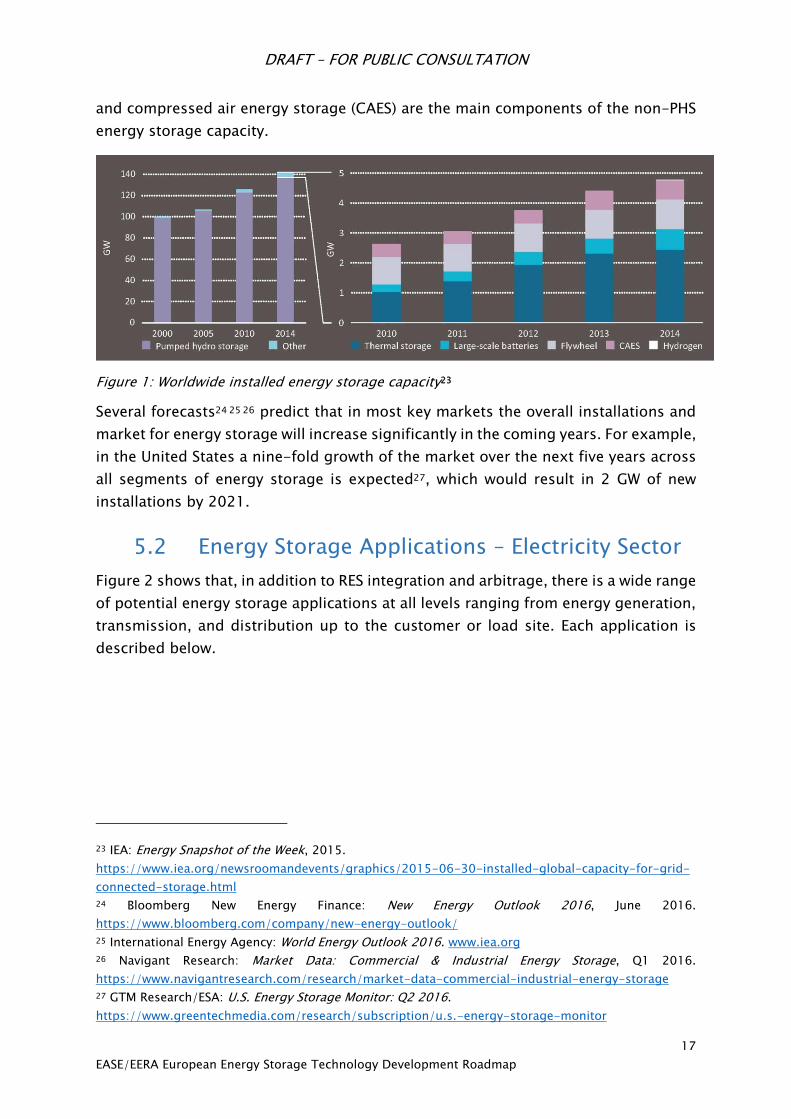
In 2015, installed large-scale energy storage capacity world-wide was estimated at
150 GW with approximately 96% of this capacity consisting of pumped hydro storage
(PHS).22 More than 70% of new installations completed in 2014 are still PHS. The
development of worldwide installed energy storage capacity in recent years is shown
in Figure 1. It shows that thermal energy storage, large-scale batteries, flywheels,
22 IEA: Tracking Clean Energy Progress, 2016.
https://www.iea.org/publications/freepublications/publication/tracking-clean-energy-progress-
2016.html
DRAFT – FOR PUBLIC CONSULTATION
17
EASE/EERA European Energy Storage Technology Development Roadmap
and compressed air energy storage (CAES) are the main components of the non-PHS
energy storage capacity.
Figure 1: Worldwide installed energy storage capacity23
Several forecasts24
25
26 predict that in most key markets the overall installations and
market for energy storage will increase significantly in the coming years. For example,
in the United States a nine-fold growth of the market over the next five years across
all segments of energy storage is expected27, which would result in 2 GW of new
installations by 2021.
5.2 Energy Storage Applications – Electricity Sector
Figure 2 shows that, in addition to RES integration and arbitrage, there is a wide range
of potential energy storage applications at all levels ranging from energy generation,
transmission, and distribution up to the customer or load site. Each application is
described below.
23 IEA: Energy Snapshot of the Week, 2015.
https://www.iea.org/newsroomandevents/graphics/2015-06-30-installed-global-capacity-for-grid-
connected-storage.html
24 Bloomberg New Energy Finance: New Energy Outlook 2016, June 2016.
https://www.bloomberg.com/company/new-energy-outlook/
25 International Energy Agency: World Energy Outlook 2016. www.iea.org
26 Navigant Research: Market Data: Commercial & Industrial Energy Storage, Q1 2016.
https://www.navigantresearch.com/research/market-data-commercial-industrial-energy-storage
27 GTM Research/ESA: U.S. Energy Storage Monitor: Q2 2016.
https://www.greentechmedia.com/research/subscription/u.s.-energy-storage-monitor

DRAFT – FOR PUBLIC CONSULTATION
18
EASE/EERA European Energy Storage Technology Development Roadmap
Generation/Bulk
Services
Ancillary
Services
Transmission
Infrastructure
Services
Distribution
Infrastructure
Services
Customer
Energy
Management
Services
Arbitrage Primary frequency
control
Transmission
investment
deferral
Capacity support End-user peak
shaving
Electric supply
capacity
Secondary
frequency control
Angular stability Contingency grid
support
Time-of-use
energy cost
management
Support to
conventional
generation
Tertiary
frequency control
Transmission
support
Distribution
investment
deferral
Particular
requirements in
power quality
Ancillary services
RES support
Frequency
stability of weak
grids
Distribution
power quality
Maximising self-
production &
self-consumption
of electricity
Capacity firming Black start Dynamic, local
voltage control
Demand charge
management
Curtailment
minimisation
Voltage support Intentional
islanding
Continuity of
energy supply
Limitation of
upstream
disturbances
New ancillary
services
Limitation of
upstream
disturbances
Limitation of
upstream
disturbances
Reactive power
compensation
Reactive power
compensation
EV integration
Figure 2: Overview of energy storage applications. Source: EASE
Generation/Bulk Services
Arbitrage is the practice of taking advantage of an electricity price difference
in the wholesale electricity market. It is the use of storage to buy energy at a
low price and sell it at a higher price.
Electric supply capacity is the use of energy storage in place of a combustion
turbine to provide the system with peak generation capacity.
Support to conventional generation is related to the optimisation of their
operation:
Generator bridging: consists in the ability of energy storage systems
(ESS) to pick up a generator load while the generator is stopping, until
DRAFT – FOR PUBLIC CONSULTATION
19
EASE/EERA European Energy Storage Technology Development Roadmap
a new generator starts up or the same generator is restarted. ESS can
also avoid stopping the unit (and the associated starting costs) by
charging in moments of low load.
Generator ramping: consists in the ability of ESS to pick up strong and
fast load variations, giving enough time for a given generator to ramp-
up/-down its production level according to the optimal technical
recommendations to meet load variation at stake.
Hedging imbalance: charges due to deviations of final physical
notifications.
Ancillary services RES support is the use of energy storage to help intermittent
renewable generation to contribute to ancillary services by keeping some
reserve power, thus “wasting” a part of the down regulation of non-
dispatchable RES.
Capacity firming is the use of energy storage to make variable RES output more
constant during a given period of time. Energy storage is used to store variable
energy production (wind or solar) during hours of peak production regardless
of demand. This energy is then discharged to supplement generation when the
variable energy unexpectedly reduces its output. This application also includes
RES smoothing, i.e. balancing short duration intermittency from wind
generation caused by variation of wind speed and from photovoltaic (PV)
generation due to shading caused by terrestrial obstructions such as clouds or
trees.
Curtailment minimisation: use of energy storage to absorb variable RES (wind
or solar) that cannot be injected into the electricity grid and to either deliver it
to the electricity grid when needed or convert it into another energy vector
(gas, fuel or heat) to be delivered to the relevant grid.
Limitation of upstream disturbances: energy storage is used to limit the
disturbances caused by the distributed variable RES generators (wind or PV):
Short duration:
• Reduce output volatility related to short-duration variation of
wind or PV generation output, lasting seconds to a few minutes.
• Improve power quality: reactive power, harmonics, voltage
flicker, transmission line protection, transient stability, dynamic
stability, and system voltage stability.
Long duration:
• Reduce output variability related to natural wind speed variability
over durations of several minutes to a few hours.
• Transmission congestion relief.
• Backup for unexpected wind/PV generation shortfall.

DRAFT – FOR PUBLIC CONSULTATION
20
EASE/EERA European Energy Storage Technology Development Roadmap
• Reduce minimum load violations.
Ancillary Services
Primary frequency control has as its objective to maintain a balance between
generation and consumption (demand) within the Synchronous Area. It aims
to stabilise the system frequency at a stationary value after a disturbance or
incident in the time-frame of seconds, but without restoring the system
frequency and the power exchanges to their reference values. Traditionally,
the providers of this service have 30 seconds to deploy to full power. Some
energy storage technologies can be deployed within a fraction of a second.
Secondary frequency control is a centralised automatic control that adjusts the
active power production of the generating units to restore the frequency and
the interchanges with other systems to their target values following an
imbalance. While primary control limits and stops frequency excursions,
secondary control brings the frequency back to its target value.
Tertiary frequency control is used to restore the primary and secondary
frequency control reserves, to manage congestions in the transmission
network, and to bring the frequency and the interchanges back to their target
value when the secondary frequency control is unable to perform this last task.
Frequency stability of weak grids is a service that aims to maintain the
frequency stability by helping avoid load shedding on islands due to the very
prompt response of distributed energy storage systems.
Black start is the use of energy storage to restore the system or a power plant
after a black-out, as some electricity is needed which cannot be drawn from
the grid.
Voltage support serves to maintain voltage through injecting or absorbing
reactive power by means of synchronous or static compensation. Different
kinds of voltage control are implemented by individual TSOs, based on their
own policies:
Primary voltage control is a local automatic control that maintains the
voltage at a given bus at its set point.
Secondary voltage control is a centralised automatic control that
coordinates the actions of local regulators in order to manage the
injection of reactive power within a regional voltage zone.
Tertiary voltage control refers to the manual optimisation of the reactive
power flows across the power system.
New ancillary services dedicated to RES integration at high RES levels include
synchronous inertia, ramping margin, fast frequency response, dynamic
reactive response, etc.
DRAFT – FOR PUBLIC CONSULTATION
21
EASE/EERA European Energy Storage Technology Development Roadmap
Transmission
Transmission investment deferral is the use of energy storage to defer any
transmission infrastructure upgrade and so to solve transmission congestion
issues.
Angular stability refers to the use of energy storage to charge and discharge
high levels of energy in short periods when an accident occurs.
Transmission support is the use of energy storage to improve the performance
of the transmission system by compensating for electrical anomalies and
disturbances such as voltage sag, unstable voltage, and sub-synchronous
resonance.
Distribution
Capacity support is the use of an energy storage unit to shift load from peak
to base load periods to reduce maximum currents flowing though constrained
grid assets. This supports the integration of renewable electricity sources.
Contingency grid support is the use of energy storage to support the grid
capacity and voltage to reduce the impacts of the loss of a major grid
component. Energy storage might also be useful in emergency situations, for
example after the loss of a major component of the distribution grid.
Distribution investment deferral is the use of energy storage to defer
distribution infrastructure upgrades.
Distribution power quality refers to the use of energy storage by the
distribution system operator (DSO) to maintain the voltage profile within
acceptable limits, which increases the quality of supply (less probability of
black out or interruptions).
Dynamic local voltage control aims to maintain the voltage profile within
admissible contractual or regulatory limits. In distribution grids, voltage
support can rely both on reactive power and active power modulations.
Intentional islanding refers to of an intentional or unintentional islanding of a
distribution grid, whereby energy storage can be used to improve system
reliability by energising a feeder during an outage.
Limitation of upstream disturbances relates to the fact that DSOs have a
network access contract with one or more TSOs which requires them to limit
the disturbances they cause on upstream high voltage grids to contractual
values. If these limits are exceeded, some types of energy storage systems can
help comply with these commitments by performing active filtering.
DRAFT – FOR PUBLIC CONSULTATION
22
EASE/EERA European Energy Storage Technology Development Roadmap
Reactive power compensation is the contribution of energy storage to reactive
power compensation by reducing the amount of reactive energy drawn from
the transmission system and charged by the transmission system operator to
the distribution system operator.
Customer Energy Management Services
End-user peak shaving is the use of energy storage devices by customers such
as industrials for peak shaving, or smoothing of own peak demand, to
minimise the part of their invoice that varies according to their highest power
demand.
Time-of-use energy cost management is the use of energy storage to be
charged when the rates are low and to be consumed during peak times, with
the aim of reducing the invoice of final users.
Particular requirements in power quality has as its objective to use energy
storage to provide a high level of power quality above and beyond what the
system offers (e.g. critical load) to some customers.
Maximising self-production & self-consumption is the use of energy storage
in markets with high energy costs to increase self-consumption in
combination with a renewable energy source. A common example is the
combination of batteries and photovoltaics.
Demand charge management is the use of energy storage to reduce the overall
customer costs for electric service by reducing demand charges during peak
periods specified by the utility.
Continuity of energy supply relates to the ability of an energy storage device
to substitute the network in case of interruption, thereby reducing the damage
for industry and households in case of blackout. These devices are often called
uninterruptable power supply (UPS) units.
Limitation of upstream disturbances is the use of energy storage for the
limitation of disturbances transmitted at upper levels.
Compensation of the reactive power refers to the ability of energy storage
devices connected via a power electronics converter to locally compensate the
reactive power and thereby influence mainly voltage.
Electric Vehicles (EV) Integration is the use of EVs or plug-in hybrid electric
vehicles (PHEV) to provide vehicle to grid (V2G) functions to contribute to grid
balancing.

DRAFT – FOR PUBLIC CONSULTATION
23
EASE/EERA European Energy Storage Technology Development Roadmap
5.3 Energy Storage Applications – Sector Coupling
In addition to the electrical applications outlined above, energy storage is able to
provide additional services to the energy system that can loosely be grouped under
the “sector coupling” heading. These are services that can help provide competitive
flexibility to the EU electricity system by integrating the electricity, heating & cooling,
and transport sectors.
These applications include:
Large-scale, long-term (weekly, monthly or seasonal) energy storage of
renewable electricity, which can be provided by chemical energy storage or
thermal energy storage. Underground Thermal Energy Storage (UTES), for
example, can provide a solution for regions that have a clear seasonal dip and
peak in heating demand, since it allows for the storage of surplus heat in the
summertime for use in the winter.
Waste heat recovery for power plants and industrial processes. In industrial
processes, waste heat is often generated at completely different locations and
temperature levels, which hampers the integration of this energy into the
system. Thermal energy storage (TES) can solve the mismatch by recovering
waste heat and storing it for a later use. This can lead to a decrease in CO2
emissions as well as economic and energy savings28.
5.4 Introduction to Energy Storage Technologies
Energy storage technologies are commonly classified according to their type, or
family, as seen in Figure 3. There are five energy storage families. The members of a
family may change in accordance with technological evolutions, but the five
categories reflect the five storage principles. Therefore, the examples in each
category should not be seen as an exhaustive list of potential family members.
28 Laia Miró, Jaume Gasia, Luisa F. Cabeza: Thermal energy storage (TES) for industrial waste
heat (IWH) recovery: A review. Applied Energy Volume 179, 1 October 2016, Pages 284–30.
DRAFT – FOR PUBLIC CONSULTATION
24
EASE/EERA European Energy Storage Technology Development Roadmap
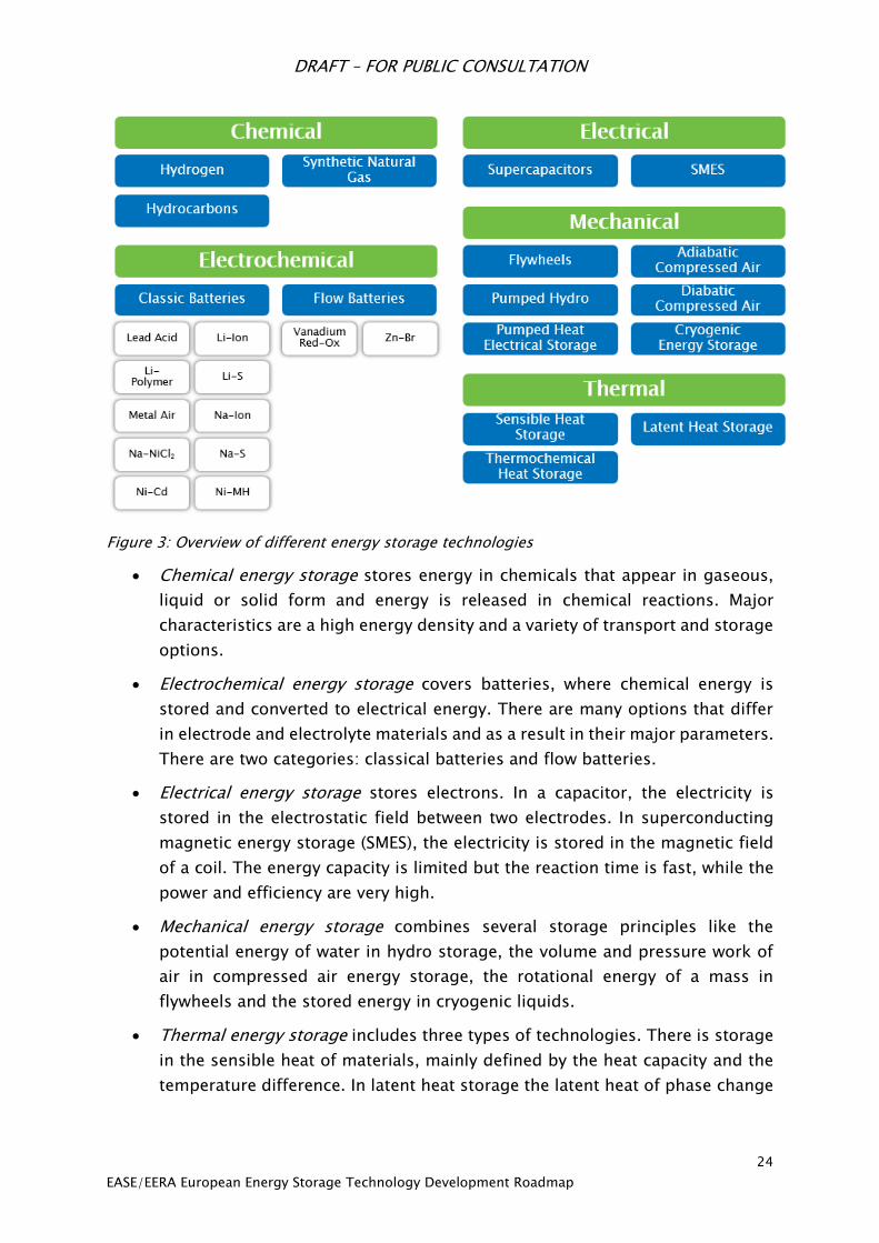
Figure 3: Overview of different energy storage technologies
Chemical energy storage stores energy in chemicals that appear in gaseous,
liquid or solid form and energy is released in chemical reactions. Major
characteristics are a high energy density and a variety of transport and storage
options.
Electrochemical energy storage covers batteries, where chemical energy is
stored and converted to electrical energy. There are many options that differ
in electrode and electrolyte materials and as a result in their major parameters.
There are two categories: classical batteries and flow batteries.
Electrical energy storage stores electrons. In a capacitor, the electricity is
stored in the electrostatic field between two electrodes. In superconducting
magnetic energy storage (SMES), the electricity is stored in the magnetic field
of a coil. The energy capacity is limited but the reaction time is fast, while the
power and efficiency are very high.
Mechanical energy storage combines several storage principles like the
potential energy of water in hydro storage, the volume and pressure work of
air in compressed air energy storage, the rotational energy of a mass in
flywheels and the stored energy in cryogenic liquids.
Thermal energy storage includes three types of technologies. There is storage
in the sensible heat of materials, mainly defined by the heat capacity and the
temperature difference. In latent heat storage the latent heat of phase change
DRAFT – FOR PUBLIC CONSULTATION
25
EASE/EERA European Energy Storage Technology Development Roadmap
of materials is used and thermochemical reactions are a further option for
thermal energy storage.
A detailed explanation of each kind of energy storage is given in chapter 6.
5.5 European Competences in Energy Storage
Chemical Storage
Chemical storage is an area that has shown rapid development in Europe in recent
years. Considerable funding from both the EU and Member States has created a
vibrant research community in the production, storage, and conversion of hydrogen,
which can be re-electrified via fuel cells. As with batteries, new innovative materials
and devices have created a range of technological options for exploitation for
industry. Many projects in power-to-gas are emerging in Germany and other
European countries. Indeed, the majority of hydrogen storage projects worldwide are
currently installed in Europe29. Most demonstration projects envisage the use of
hydrogen for mobility purposes or wholesale via gas grid, but only a few of them
include large-scale storage and electrification in their scope. Chemical storage is well
suited to facilitate the integration of a large share of RES, which will play an
increasingly important role in Europe. The European chemical storage industry is
therefore expected to grow significantly.
Electrochemical Storage
The European industry’s position is strong in the most mature electrochemical
storage technologies, such as Lead-Acid30 & Ni-Cd batteries. The situation is
different for the Li-ion batteries segment, which is currently dominated by Asian
actors (chiefly located in Japan, Korea, and China)31 because of its wide use in
products such as mobile phones and portable computers. With the increasing use of
Li-ion batteries in both automotive and grid applications, Europe will need to develop
its own production capacity in this field. Li-ion batteries are excellent for both
cyclability and weight, and are rapidly declining in cost. While many other chemistries
are proposed as future options, continuous improvement of Li-ion batteries may be
one of the main drivers for electrochemical energy storage for many years.
29 US Department of Energy: Global Energy Storage Database, 2016.
http://www.energystorageexchange.org/projects
30 European Commisison: SET‐Plan ACTION n°7 –Declaration of Intent: "Become competitive in the global
battery sector to drive e‐mobility forward", 12 July 2016.
https://setis.ec.europa.eu/system/files/action7_declaration_of_intent_0.pdf
31 Freedonia: World Lithium, 2015. http://www.freedoniagroup.com/industry-study/world-lithium-
3331.htm

DRAFT – FOR PUBLIC CONSULTATION
26
EASE/EERA European Energy Storage Technology Development Roadmap
Some NaS battery projects have been set up in France, Germany and UK, although
most of these projects are located in Japan and the United States. M-Air is considered
as a valuable candidate to substitute the Li-Ion batteries in the upcoming 10-15 years
because of expected developments in performance. Na-Ion batteries are also
considered a possible successor for Li-ion batteries due to significant cost reductions
expected in the coming years. Although it was first developed in the United States,
Li-S technology is also considered as one of the applicants to replace Li-Ion in the
upcoming 5-10 years in Europe, thanks to its larger energy density and the
employment of low cost materials. Nonetheless, all of these materials will need
significant improvements in cyclability before they will be viable candidates to
compete with Li-ion. In the meantime, Li-ion will continue to improve in performance,
supported by a huge market, making it more difficult for the competition.
Likewise, Na/NiCI2 is mainly used in public transport and is manufactured in the EU
(first) since 1999 and then in the United States. Finally, flow batteries are a mature
technology: they have been produced since the early 1970s in the United States, then
in Asia and Australia. In Europe, the research is chiefly focused on small devices and
on developing cost-effective new membranes and increasing the power density of
the cell. There are only a few companies worldwide offering redox flow batteries to
the market, all of which are located in Europe32.
The joint development of the European battery market for transport and stationary
applications represents a big opportunity for strong industrial suppliers, supported
by a strong European R&D network to be able to compete against the Asian industrials
in a sector where European competences are rapidly increasing. Additionally, Europe
is a leader in system integration of renewables and, increasingly, storage devices and
further efforts are expected in the coming years.
Electrical Storage
Ultracapacitors
The first discoveries in this field were made in 1957. Since the early 1980s niche uses
have been seen and a broader deployment of Electrochemical Capacitors (ECs) has
accelerated over the last 20 years. Ultracapacitors have been in commercial use for
decades in both transportation and grid back up applications such as wind pitch
control systems, demonstrating the lowest cost of ownership in high power/low
energy and rapid cycling applications. Their long cycle life (~1 million cycles) and
calendar life (10-25 years) coupled with a wide operating temperature range (-40-
65°C) are well matched with existing grid assets. The deployment of ultracapacitors
32 European Parliament: Energy Storage: Which Market Designs and Regulatory Incentives are Needed?,
2015. www.europarl.europa.eu/RegData/etudes/STUD/.../IPOL_STU(2015)563469_EN.pdf
DRAFT – FOR PUBLIC CONSULTATION
27
EASE/EERA European Energy Storage Technology Development Roadmap
in grid energy storage systems – as a stand-alone energy storage technology or
hybridised with batteries – is rapidly growing.
Future research and development activities are focused towards improving energy
density of the core technology, and power electronics that support the control and
management of ultracapacitors combined with batteries or another secondary
storage technology. In Europe the main producers of ultracapacitors are based in
Germany and France; however, the larger producers are located in Asian countries.
Superconducting Magnetic Energy Storage (SMES)
In recent years, several successful R&D projects on SMES have been carried out in
Europe but there is currently no European commercial supplier of SMES. The main
competences are within R&D institutes, which have successfully developed several
demonstrators and prototypes. Within a R&D project in France, the Centre National
de la Recherche Scientifique (CNRS) developed one of the first high-temperature
superconducting SMES with a capacity of 800 kJ and 400 kJ and Bi2212 material
operating at 20 K33. At the Karlsruhe Institute of Technology (KIT) in Germany, a
hybrid concept with a SMES, in combination with hydrogen, has been studied in
detail34 and a first small MgB2 superconducting coil has been built and tested. This
combines the fast SMES operation with bulk hydrogen storage and seems interesting
for large capacities with liquid hydrogen storage. The Institut de Ciència de Materials
de Barcelona (ICMAB) in Spain also developed SMES applications and built a
demonstrator. Additionally, very recently, a new SMES project was launched in Italy
with Columbus, ENEA, RES35, SPIN and the University Bologna to setup a 300 kJ,
100 kW SMES prototype system with MgB2 for a pioneering application in electricity
systems. This last SMES application seems promising because studies have shown
that a combination of SMES and battery systems could yield cost reductions and a
significant increase in the lifetime of the battery system.
Mechanical Storage
Compressed Air
This energy storage system is differentiated between two technologies: Adiabatic
Compressed Air Energy Storage (A-CAES) and Diabatic Compressed Air Energy
Storage (D-CAES). Both systems are based on air compression and air storage in
33 A. Badel, P. Tixador, K. Berger and M. Deleglise, “Design and preliminary tests of a twin coil HTS SMES
for pulse power operation” Supercond. Sci. Technol. 24 (2011) 055010, doi:10.1088/0953-
2048/24/5/055010.
34 M. Sander, R. Gehring and H. Neumann, „LIQHYSMES—A 48 GJ Toroidal MgB2-SMES for Buffering
Minute and Second Fluctuations”, IEEE Transactions on Applied Superconductivity, Vol. 23, No. 3, June
2013.
35 Reliable Environmental Solutions.
DRAFT – FOR PUBLIC CONSULTATION
28
EASE/EERA European Energy Storage Technology Development Roadmap
geological underground voids (mainly salt caverns). A-CAES systems are in the
process of demonstration and are not yet commercially available. In recent years,
several advanced projects, such as ADELE36 in Germany and AA-CAES37 in the UK,
have been set up. In the future, A-CAES systems have the potential to provide a large
part of the necessary European storage capacity, but this will depend on some
geological characteristics in order to build underground storage capacity.
On the other hand, D-CAES systems are already deployed. There are two existing
plants: one in Huntorf, Germany and one in McIntosh, Alabama, USA. The first R&D
project started in Germany in 1978, after which the United States took the lead on D-
CAES development. Currently, research is much more focused on upgrading D-CAES
with a Thermal Energy Storage device, which can make deployment achievable within
the coming years. This system is envisaged to increase variable renewable energy in
the generation mix by 2030. Therefore, D-CAES is the only recognised and proven
bulk storage technology other than PHS currently available on a commercial scale in
Europe.
Flywheel
Kinetic energy storage based on flywheels is characterised by a fast response, high
power and energy density, as well as the possibility to decouple power and energy in
the design stage. Flywheel is a mature technology completely introduced in the
industrial market. More than 20 manufacturers have been identified and many
research centres are focused on this technology as well. However, some technological
aspects need to be improved. The industry for this sector is located mainly in the
United States, as are the majority of R&D centres focused on flywheels.
In Europe, there flywheel projects are installed in in France, United Kingdom,
Germany, Spain, the Portuguese islands, and, in particular, in Ireland where a hybrid
flywheel plant was built in 201538. The Irish project (promoted by Schwungrad
Energie39) is attracting interest from national grids across Europe, which plan to
36 Adiabatic Compressed Air Energy Storage for Electricity Supply (ADELE): Compressed air instead of a
pumped-storage power plant, 18 October 2015. http://forschung-
energiespeicher.info/en/projektschau/gesamtliste/projekt-
einzelansicht//Druckluft_statt_Pumpspeicher/
37 CORDIS: Advanced adiabatic compressed air energy storage (AA-CAES) 2005.
http://cordis.europa.eu/project/rcn/67580_en.html
38 The hybrid flywheel is a disruptive innovation with the potential to revolutionise the system services
market, decoupling its provision from electricity generation by delivering energy-less system services
39 Company website: http://schwungrad-energie.com/
DRAFT – FOR PUBLIC CONSULTATION
29
EASE/EERA European Energy Storage Technology Development Roadmap
increase their renewable energy penetration in the years ahead4041. The flywheel
project has received funding from both the European Commission and the Irish
government.
Liquid Air
Liquid Air Energy Storage (LAES), also referred to as cryogenic energy storage, uses
liquid air as an energy vector. LAES technologies have been primarily developed by
two British universities: the University of Newcastle upon Tyne and the University of
Leeds. The former developed the LAES concept for peak shaving in 1977. The
University of Leeds has carried out more research on LAES in collaboration with the
British company Highview Power Storage and the Japanese company Mitsubishi Heavy
Industries and Hitachi. Europe, and more particularly the UK, was thus at the forefront
of the development of LAES technologies.
Today, the UK remains a world leader in LAES technologies. Highview Power Storage
is building one of the first pre-commercial LAES technology demonstrators.
Supported by UK government funding of more than £8 million, this 5 MW LAES
technology system is expected to begin operations in 2017.42 Thus, the combined
work of technology and innovation centres, growth-hungry companies with
government support enabled the UK and thus Europe to become the world leader in
term of LAES.
Pumped Hydro Storage (PHS)
PHS is the largest storage technology in Europe (and indeed, worldwide). Currently,
more than 50 GW net pumped hydro storage capacity43 (around 30% of global
capacity) is in operation in the EU, representing 12% of total net electrical installed
capacity in the EU44. By 2020, installed PHS capacity in Europe is expected to reach
47.8 GW, a rise of almost 16 % in 10 years45, since PHS is the most mature and cost-
effective large-scale storage solution available in Europe today. The European
40 Arthur Neslen: New energy storage plant could 'revolutionise' renewable sector, The Guardian, 8 April
2015. https://www.theguardian.com/environment/2015/apr/08/new-energy-storage-plant-could-
revolutionise-renewable-sector
41 Schwungrad: First Hybrid-Flywheel Energy Storage Plant in Europe announced in Ireland, 2015.
http://schwungrad-energie.com/hybrid-flywheel-energy-storage-plant-europe-announced-ireland/
42 Highview Power: Pre-Commercial LAES Technology Demonstrator, 2017. http://www.highview-
power.com/pre-commercial-laes-technology-demonstrator/
43 European Parliament: Energy Storage: Which Market Designs and Regulatory Incentives are Needed?,
2015. www.europarl.europa.eu/RegData/etudes/STUD/.../IPOL_STU(2015)563469_EN.pdf
44 U.S. Energy Information Administration (EIA): Total Electricity Installed Capacity 2014.
http://www.eia.gov/cfapps/ipdbproject/IEDIndex3.cfm?tid=2&pid=2&aid=7
45 eSTORAGE: Potential for conversion of classical PSP to variable speed units in EU15, Norway and
Switzerland, April 2016. http://www.estorage-project.eu/wp-content/uploads/2013/06/EXTRACT-of-
eStorage-D4.1-Potential-for-conversion-of-classical-PSP-to-variable-speed-units.pdf
DRAFT – FOR PUBLIC CONSULTATION
30
EASE/EERA European Energy Storage Technology Development Roadmap
hydropower sector has a technology leadership role, as European equipment
manufacturers account for two-thirds of the world market. In addition, three current
global leaders accounting for more than 50% of the global hydropower equipment
market are European companies46.
Despite the large amount of capacity installed today, there is a huge potential for new
expansion and development. The eStorage project estimates that 2291 GWh of
development-ready sites with existing reservoirs for new pumped hydro energy
storage plants exist in the EU-15, Norway, and Switzerland47. Industry and R&D
opportunities in PHS are focused on mountainous regions in Switzerland, Austria,
Germany, Spain, and Portugal. Since conventional PHS plants can only regulate their
power in generation mode, their operation in pumping mode is less flexible.
Therefore, new technologies are being developed to enhance the operational
flexibility of PHS plants48.
Thermal Storage
Sensible Heat
The most common way of thermal energy storage (TES) is sensible heat. Underground
TES are commonly used in Denmark, Sweden, the Netherlands, Norway and Germany
for the sake of seasonal storage of heat in centralised and distributed energy
systems49. In these countries underground TES (UTES) is applied together with
renewable solar or geothermal heat and electricity from photovoltaic, in combination
with district heating, whereas in other European countries UTES systems are still on
a demonstration and pilot level.
R&D is focused on the system and material level in order to achieve SET-Plan Targets
on storage density (in general sensible heat storage requires large volumes because
of its low energy density). Several developers in Germany, Slovenia, Japan, Russia,
and the Netherlands are working on new materials and techniques for TES systems,
including their integration into building walls and transportation of thermal energy
46 DNV GL: Hydropower: Part of the Renewable Family, 10 June 2015. http://www.thehea.org/macro-
economic-study-on-hydropower/ 47 eStorage: eStorage Study Shows Huge Potential Capacity of Exploitable Pumped Hydro Energy Storage
Sites in Europe, 28 April 2016. http://www.estorage-project.eu/wp-
content/uploads/2013/06/eStorage-D4.2-press-release-FINAL.pdf
48 eSTORAGE: Potential for conversion of classical PSP to variable speed units in EU15, Norway and
Switzerland, April 2016. http://www.estorage-project.eu/wp-content/uploads/2013/06/EXTRACT-of-
eStorage-D4.1-Potential-for-conversion-of-classical-PSP-to-variable-speed-units.pdf
49 IRENA publication: https://www.irena.org/DocumentDownloads/Publications/IRENA-
ETSAP%20Tech%20Brief%20E17%20Thermal%20Energy%20Storage.pdf

DRAFT – FOR PUBLIC CONSULTATION
31
EASE/EERA European Energy Storage Technology Development Roadmap
from one place to another. These new applications are now being commercialised,
and their cost, performance, and reliability will be verified50.
Latent Heat
This type of TES could be a new useful device, suitable for grid applications. Its high
heat capacity and the melting temperature of silicon made it ideal for storing a large
amount of energy. Over the last four years, there has been a strong development in
the sector and a year from now a prototype will start to operate. Australia has a
burgeoning latent heat storage industry51 supported by the Australian government52.
In Europe there are some ongoing research programs such as the one in Belgium, led
by the EnergyVille research Centre of KU Leuven, which is trying to find better
solutions for latent heat technology in terms of material improvements53. Moreover,
in Germany, Fraunhofer ISE has two research projects concentrated on Phase Change
Materials54.
Thermochemical storage
Thermochemical storage (TCS) is the third category of TES and is considered as the
least investigated storage technology though it can potentially store more energy
than sensible and latent heat55. TCS is a very promising storage field because it could
offer a higher energy density and even more important minor energy losses compared
to the other TES56.
Europe has been a pioneer in terms of thermochemical storage studies. The first TCS
studies were published in the 1970s by Swedish and Swiss researchers57 and a first
practical TCS application – the ADAM-EVA project – was launched in Germany in the
50 IRENA: Thermal Energy Storage Technology Brief, 2013.
https://www.irena.org/DocumentDownloads/Publications/IRENA-
ETSAP%20Tech%20Brief%20E17%20Thermal%20Energy%20Storage.pdf
51 1414 Degrees website: http://www.latent-heat.com/
52 Andrew Spence: Sandy Solution for Renewable Energy Storage, Renewable Energy World, 12 November
2015. http://www.renewableenergyworld.com/articles/2015/11/sandy-solution-for-renewable-
energy-storage.html
53 EnergyVille: Latent Heat Storage in Phase Changing Materials, 2016.
http://www.energyville.be/en/sheet/latent-heat-storage-phase-changing-materials
54 Fraunhofer ISE: Latent Heat Storage Projects, 2016. https://www.ise.fraunhofer.de/en/admin-
folder/business-areas-old/storage-technologies/research-topics/latent-heat-storage/projects
55 Sarada Kuravi et al.: Thermal energy storage technologies and systems for concentrating solar power
Plants, Progress in Energy and Combustion Science 39 (2013) 285-319.
http://research.fit.edu/nhc/documents/PECS.pdf
56 Yate Ding and S.B. Riffat: Thermochemical energy storage technologies for building applications: a
state-of-the-art review, Int. J. Low-Carbon Tech. (2013) 8 (2): 106-116. doi: 10.1093/ijlct/cts004
57 Wettermark G, Carlsson B, Stymne H.: Storage of Heat: A Survey of Efforts and Possibilities. Swedish
Council for Building Research, 1979.

DRAFT – FOR PUBLIC CONSULTATION
32
EASE/EERA European Energy Storage Technology Development Roadmap
early 1980s58. In 2016, thermochemical heat storages remain largely at an
experimental stage. With respect to systems based on chemical reactions, 95% of
installed systems are in R&D. Sorption storage systems are slightly more developed
with the exception of sorption heat pumps which have been fully commercialised.
The EU-financed TCSPower project and the CWS project, both German, are two
examples of recent TCS R&D projects.
58 Yate Ding and S.B. Riffat: Thermochemical energy storage technologies for building applications: a
state-of-the-art review, Int. J. Low-Carbon Tech. (2013) 8 (2): 106-116. doi: 10.1093/ijlct/cts004
DRAFT – FOR PUBLIC CONSULTATION
33
EASE/EERA European Energy Storage Technology Development Roadmap
6. Energy Storage Technologies
6.1 Chemical Energy Storage
Introduction
Chemical energy storage is based on the transformation of electrical energy into the
energy of chemical bonds. It allows an exchange of energy between different vectors
of the energy system, establishing cross-sectorial links of the power sector with the
gas, fuel and chemical sectors. The heading Power-to-X (P2X) groups a range of
generic technologies that convert renewable electricity into hydrogen, with the
possibility to combine it with CO2 to synthesise valuable gases (Power-to-Gas) and
liquids (Power-to-Liquid) which can be used as fuels or chemicals.
a) Hydrogen
Electrolyser technology uses electricity to split water (H2O) into hydrogen (H2)
and oxygen (O2). Alkaline electrolyser technology is well known and has been
utilised for about a century. Higher power density and efficiency is obtained
with proton exchange membrane (PEM) cells. Recent developments include
high temperature ceramic electrolysers based on solid oxide technology,
which can make use of CO2 and produce syngas or synfuels and plasma-
chemical conversion or plasmolysis to split CO2 or water through vibrational
excitation of the molecules in thermal non-equilibrium.
Hydrogen plays a central role in chemical energy storage59. However, its low
volumetric energy density requires compression of usually between 200 and
700 bar or liquefaction. Hydrogen has an extended versatility of use: it can be
reconverted to electrical energy for stationary applications (power and heat
generation) or mobile applications (transport) giving only water vapour as a
reaction product, transmitted in dedicated pipelines to connect production
sites with consumer sites, admixed into the existing natural gas grid to a
certain limit, converted to others fuels (methane, methanol) or used in the
chemical industry.
b) Other chemical energy carriers:
In order to increase volumetric energy density and make use of existing
infrastructure, other energy carriers and chemicals using hydrogen, carbon
dioxide or nitrogen can be used either as fuels or basis material for chemical
59 Indeed, hydrogen is the only realistic chemical storage option (except perhaps ammonia) to avoid CO2
emissions for all end users. Other chemical carriers should therefore be considered primarily for systems
including CO2 capture and storage.
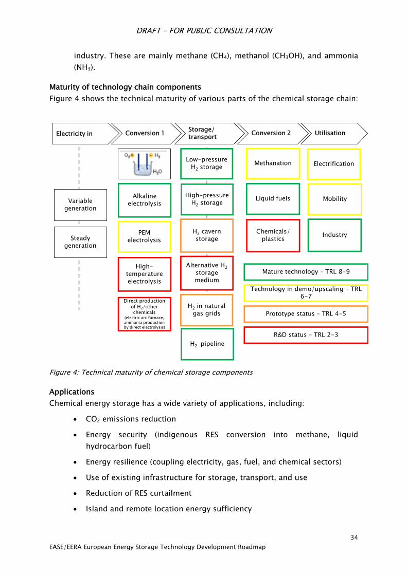
DRAFT – FOR PUBLIC CONSULTATION
34
EASE/EERA European Energy Storage Technology Development Roadmap
industry. These are mainly methane (CH4), methanol (CH3OH), and ammonia
(NH3).
Maturity of technology chain components
Figure 4 shows the technical maturity of various parts of the chemical storage chain:
Conversion 1Storage/ transport
Conversion 2 UtilisationElectricity in
Variable generation
Steady generation
PEM electrolysis
Alkaline electrolysis
High-temperature electrolysis
Low-pressure H2 storage
High-pressure H2 storage
H2 cavern storage
Alternative H2
storage medium
H2 pipeline
Methanation
Liquid fuels
Chemicals/plastics
Electrification
Mobility
Industry
H2 in natural gas grids
Direct production of H2/other chemicals
(electric arc furnace, ammonia production by direct electrolysis)
Mature technology – TRL 8-9
Technology in demo/upscaling – TRL 6-7
Prototype status – TRL 4-5
R&D status – TRL 2-3
Figure 4: Technical maturity of chemical storage components
Applications
Chemical energy storage has a wide variety of applications, including:
CO2 emissions reduction
Energy security (indigenous RES conversion into methane, liquid
hydrocarbon fuel)
Energy resilience (coupling electricity, gas, fuel, and chemical sectors)
Use of existing infrastructure for storage, transport, and use
Reduction of RES curtailment
Island and remote location energy sufficiency

DRAFT – FOR PUBLIC CONSULTATION
35
EASE/EERA European Energy Storage Technology Development Roadmap
Grid services (voltage, frequency stability): very fast reacting devices
balancing variable renewable energy sources
Energy arbitrage
Seasonal energy storage (GWh to TWh scale)
Electrification in the chemical industry by providing hydrogen carriers (H2,
NH3) or C1 building blocks (methane, methanol)
Indirect electrification of aviation, marine sector and transport by cars and
trucks by synthetic fuels based on electricity
SET Plan targets60 for electrolysis and hydrogen storage technologies towards 2030
and beyond
Table 1: SET Plan targets Alkaline Technology
Property State-of-the-art Target 2020-2030 Ultimate goal
Operating current density (A/cm2) 0.2–0.5 0.1–1 0–2
Operating temperature (°C) ambient – 120 ambient - 150 ambient - >150
Operating pressure (bars) 1-200 1-350 1-700
Durability (h) 105 > 105 > 105
Cyclability poor improved high
Production capacity of electrolysis units 1-100 kg/hour
(≈ 10-1000
Nm3/hour)
> 100 kg/hour
(≈ 1000 Nm3/hour)
> 1000 kg/hour
(≈ 10 000 Nm3/hour)
Non-energy cost (€/kg H2) <5 2 1
Table 2: SET Plan targets PEM Technology
Property State-of-the-art Target 2020-2030 Ultimate goal
Operating current density (A/cm2) 0 – 2 0 – 2 0 – 5
Operating temperature (°C) 50-80 80-120 100-150
Operating pressure (bar) 1-50 1-350 1-700
Durability (h) 104 104 – 5·104 > 105
Production capacity of electrolysis units 1-30 kg/hour
(≈ 10-300 Nm3/hour)
> 30 kg/hour
(≈ 300 Nm3/hour)
> 100 kg/hour
(≈ 1000 Nm3/hour)
Energy efficiency (kWh/kg H2 at 80°C, 1
A.cm-2) 56 < 50 48
Non-energy cost (€/kg H2) 5 2 1
60 Commission Staff Working Paper: Materials Roadmap Enabling Low Carbon Energy Technologies,
2011. http://setis.ec.europa.eu/activities/materials-roadmap/Materials_Roadmap_EN.pdf/view

DRAFT – FOR PUBLIC CONSULTATION
36
EASE/EERA European Energy Storage Technology Development Roadmap
Table 3: SET Plan targets Solid Oxide Technology
Property State-of-the-art Target 2020-2030 Ultimate goal
Operating temperature (°C) 800-950 700-800 600-700
Operating pressure (bars) 1-5 1-30 1-100
Operating current density (A/cm2) 0–0.5 0–1 0–2
Area Specific Resistance (Ω.cm2) 0.3-0.6 0.2–0.3
Enthalpic efficiency 100% at 0.5 A/cm2 100% at 1 A/cm2 100% at 2 A/cm2
Durability (h) 103 104 105
Electrical modulation Unknown 0-100 0-100
Load cycles Unknown 10,000 > 10,000
Start-up time (h) 12 1-6 < 1-6
Production capacity of electrolysis units <1 kg/hour
(≈ 10 Nm3/hour)
10 kg/hour
(≈ 100 Nm3/hour)
100 kg/hour
(≈ 1000 Nm3/hour) Non-energy cost (€/kg H2) 5 2 1
Table 4: SET Plan targets Plasmology CO2
Property State-of-the-art Target 2020-2030 Ultimate goal
Power density (W/cm3) 10 100 1000
Enthalpic Efficiency (Enthalpy/power in) 50% 70% 80%
Operating temperature (°C) ambient ambient - 150 ambient - >150
Operating pressure (bars) 0.2-0.5 0.5 - 1 1 – 1.2
Durability (h) 105 > 105 > 105
Separation effluent gases in constituents poor improved high
Use of scarce materials None None None
Production capacity (kg/hr) 1 10 > 100
Non-energy cost (€/kg CO) <1 0.1 0.05
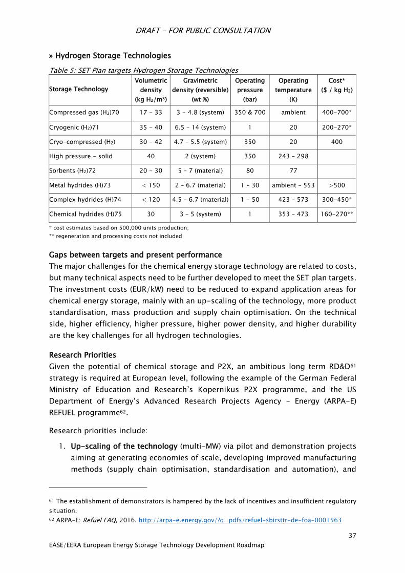
DRAFT – FOR PUBLIC CONSULTATION
37
EASE/EERA European Energy Storage Technology Development Roadmap
» Hydrogen Storage Technologies
Table 5: SET Plan targets Hydrogen Storage Technologies
Storage Technology
Volumetric
density
(kg H2/m3)
Gravimetric
density (reversible)
(wt %)
Operating
pressure
(bar)
Operating
temperature
(K)
Cost*
($ / kg H2)
Compressed gas (H2)70 17 - 33 3 - 4.8 (system) 350 & 700 ambient 400-700*
Cryogenic (H2)71 35 - 40 6.5 – 14 (system) 1 20 200-270*
Cryo-compressed (H2) 30 - 42 4.7 – 5.5 (system) 350 20 400
High pressure - solid 40 2 (system) 350 243 – 298
Sorbents (H2)72 20 - 30 5 – 7 (material) 80 77
Metal hydrides (H)73 < 150 2 – 6.7 (material) 1 – 30 ambient – 553 >500
Complex hydrides (H)74 < 120 4.5 – 6.7 (material) 1 - 50 423 – 573 300-450*
Chemical hydrides (H)75 30 3 – 5 (system) 1 353 – 473 160-270**
* cost estimates based on 500,000 units production;
** regeneration and processing costs not included
Gaps between targets and present performance
The major challenges for the chemical energy storage technology are related to costs,
but many technical aspects need to be further developed to meet the SET plan targets.
The investment costs (EUR/kW) need to be reduced to expand application areas for
chemical energy storage, mainly with an up-scaling of the technology, more product
standardisation, mass production and supply chain optimisation. On the technical
side, higher efficiency, higher pressure, higher power density, and higher durability
are the key challenges for all hydrogen technologies.
Research Priorities
Given the potential of chemical storage and P2X, an ambitious long term RD&D61
strategy is required at European level, following the example of the German Federal
Ministry of Education and Research’s Kopernikus P2X programme, and the US
Department of Energy’s Advanced Research Projects Agency - Energy (ARPA-E)
REFUEL programme62.
Research priorities include:
1. Up-scaling of the technology (multi-MW) via pilot and demonstration projects
aiming at generating economies of scale, developing improved manufacturing
methods (supply chain optimisation, standardisation and automation), and
61 The establishment of demonstrators is hampered by the lack of incentives and insufficient regulatory
situation.
62 ARPA-E: Refuel FAQ, 2016. http://arpa-e.energy.gov/?q=pdfs/refuel-sbirsttr-de-foa-0001563
DRAFT – FOR PUBLIC CONSULTATION
38
EASE/EERA European Energy Storage Technology Development Roadmap
better integrating electrolyser technology with downstream processes with the
overall objective of decreasing the total cost and improving efficiency.
2. Materials and electrochemical process research and development to decrease
the total cost of the technology: use of low cost material, new designs and
manufacturing methods, high current densities, large area cells, gas separation
membranes, improved durability of the equipment, decreased use of noble
metals, reduction of the service and maintenance needs, and increased energy
density in hydrogen storage.
3. Materials and electrochemical process research and development to improve
the overall performance of the technology: increase system efficiency, going to
higher temperature, improve catalysts, high pressure electrolysis, improved
interfacing between the various technologies and improved design of single
equipment and the overall system.
4. Research, demonstration and industrial optimisation of:
a. Catalytic formation processes for chemical fuels (gas or liquids) by
conversion of hydrogen, nitrogen and CO2 to: ammonia, methane,
methanol, dimethyl-ether (DME), oxy-methylene ether (OME), synthetic
kerosene, formic acid, and other chemicals;
b. The integration of these processes with upstream (renewables,
electrolysers, CO2 streams) and downstream processes (industrial
processes, distribution networks);
c. The applications using these chemical fuels: fuel cells, combustion engines,
gas turbines.
5. Knowledge build up for health and safety, environmental compatibility
(emissions, emission control), reduction of risk of pipeline leakage and
corrosion due to hydrogen admixture, existing legal boundary conditions and
their further development concerning: production of chemical energy carriers,
storage, transport, handling and use, economy, sustainability of overall
solutions.
Recommendations for Research Funding, Infrastructure, and Incentives
In the short term, R&D projects should continue to be supported via direct incentives
to allow the up-scaling of technology, cost reductions, and a better integration of the
various technologies. This requires general support for the entire chain including
electrolysers, plasmolysers, compression and storage technologies, catalytic
conversion technologies, and re-conversion technologies.
At EU level, we advise the creation of a 10-year R&D programme similar to the
Kopernikus Power-to-X programme of the German Federal Ministry of Education and

DRAFT – FOR PUBLIC CONSULTATION
39
EASE/EERA European Energy Storage Technology Development Roadmap
Research (BMBF). As part of this programme, a national research platform is being
established to focus on the development of key P2X technologies over the next ten
years, with the support of a wide range of research institutions, industry players, and
civil society organisations. The aim is to bring P2X solutions from the research or
prototype stage to the deployment stage. One unique aspect of the programme is
that it combines a long-term project structure with a flexible steering mechanism to
adapt to the rapidly changing environment. The project is jointly funded by the BMBF
and industry partners.
In the medium term (2020), direct incentives should be progressively replaced by
market based incentives to recompense the renewable (or low-carbon) characteristics
of the end product in the overall decarbonisation on the EU energy system comprising
the power, gas, mobility and industrial sectors. Also on the regulatory side, a number
of barriers preventing the competitiveness and deployment of chemical energy
storage (e.g., high cost burdens from grid fees or other levies) must be removed.
DRAFT – FOR PUBLIC CONSULTATION
40
EASE/EERA European Energy Storage Technology Development Roadmap
6.2 Electrochemical Energy Storage
Batteries are electrochemical energy storage devices based on different specific
chemical systems that are tailored to a variety of applications.
Until recently, the secondary (rechargeable) battery market could be divided into
three segments:
1. Portable batteries (capacity < 6 Ah) used as a convenient power source for
consumer devices (e.g., mobile phones or laptops): segment dominated
mainly by the lithium-based batteries with the use of the nickel-based
batteries in some specific niches.
2. Industrial batteries (capacity ≥ 6 Ah) used as a convenient power source
for industrial devices either for stationary applications (e.g., UPS) or for
mobile applications (e.g. forklifts): segment mainly dominated by the lead-
based batteries with the use of nickel-based and sodium-based batteries
in some specific niches.
3. Starting-Lighting-Ignition (SLI) batteries used for automobile devices:
segment dominated by Lead-based batteries.
In recent years, decarbonisation policies have led to the development of two new
battery segments:
1. Mobility batteries used for “Clean Vehicles”:
Electric Vehicles (EV) and Plug-in Hybrid Vehicles (PHEV): dominated by
lithium-based batteries
Hybrid Vehicles (HEV): lithium-based and Ni-MH batteries
Micro-Hybrid Vehicles: advanced lead-acid batteries with the use of
lithium-based batteries for some niches
2. Storage batteries used to provide flexibility to the electrical grid: different
battery technologies (lithium-based, sodium-based, lead-based, flow
batteries, etc.) are used according to the battery location and the services
provided. There is also a need for large-scale storage batteries to facilitate
the integration of increasing shares of RES.
Batteries are based on single electrochemical cells, each having voltages ranging from
below 1 V up to 4.1 – 4.2 V. The cells can be combined in series to yield very high
voltages if required and the series cells are assembled in parallel to achieve the
required power. Batteries hold highly attractive power densities and their round cycle
efficiency (electrical energy out over electrical energy in) is generally high – in the
range up to 70-95 %, depending on charge and discharge conditions. Because of the
basic electrochemical cells of batteries, they are highly modular and can be
manufactured for very high capacities and/or power requirements.
Electrochemical batteries consist of two or more electrochemical cells, which use
chemical reactions to create a flow of electrons – electric current. Primary elements
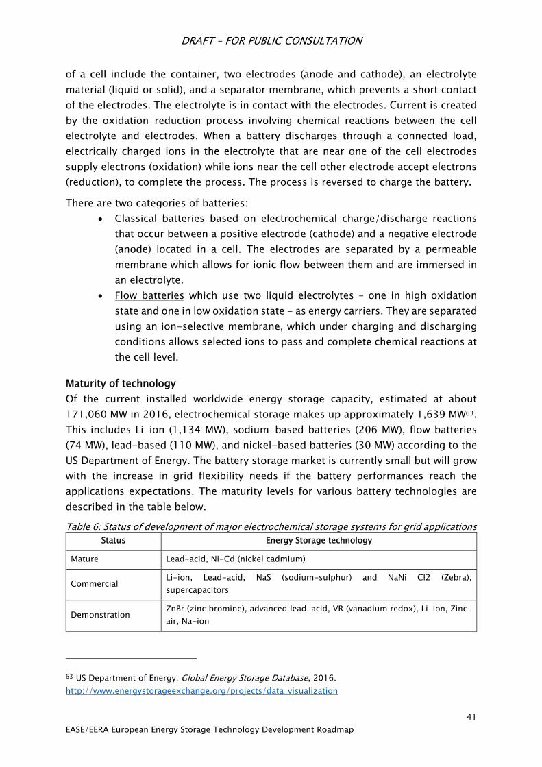
DRAFT – FOR PUBLIC CONSULTATION
41
EASE/EERA European Energy Storage Technology Development Roadmap
of a cell include the container, two electrodes (anode and cathode), an electrolyte
material (liquid or solid), and a separator membrane, which prevents a short contact
of the electrodes. The electrolyte is in contact with the electrodes. Current is created
by the oxidation-reduction process involving chemical reactions between the cell
electrolyte and electrodes. When a battery discharges through a connected load,
electrically charged ions in the electrolyte that are near one of the cell electrodes
supply electrons (oxidation) while ions near the cell other electrode accept electrons
(reduction), to complete the process. The process is reversed to charge the battery.
There are two categories of batteries:
Classical batteries based on electrochemical charge/discharge reactions
that occur between a positive electrode (cathode) and a negative electrode
(anode) located in a cell. The electrodes are separated by a permeable
membrane which allows for ionic flow between them and are immersed in
an electrolyte.
Flow batteries which use two liquid electrolytes – one in high oxidation
state and one in low oxidation state - as energy carriers. They are separated
using an ion-selective membrane, which under charging and discharging
conditions allows selected ions to pass and complete chemical reactions at
the cell level.
Maturity of technology
Of the current installed worldwide energy storage capacity, estimated at about
171,060 MW in 2016, electrochemical storage makes up approximately 1,639 MW63.
This includes Li-ion (1,134 MW), sodium-based batteries (206 MW), flow batteries
(74 MW), lead-based (110 MW), and nickel-based batteries (30 MW) according to the
US Department of Energy. The battery storage market is currently small but will grow
with the increase in grid flexibility needs if the battery performances reach the
applications expectations. The maturity levels for various battery technologies are
described in the table below.
Table 6: Status of development of major electrochemical storage systems for grid applications
Status Energy Storage technology
Mature Lead-acid, Ni-Cd (nickel cadmium)
Commercial Li-ion, Lead-acid, NaS (sodium-sulphur) and NaNi Cl2 (Zebra),
supercapacitors
Demonstration ZnBr (zinc bromine), advanced lead-acid, VR (vanadium redox), Li-ion, Zinc-
air, Na-ion
63 US Department of Energy: Global Energy Storage Database, 2016.
http://www.energystorageexchange.org/projects/data_visualization
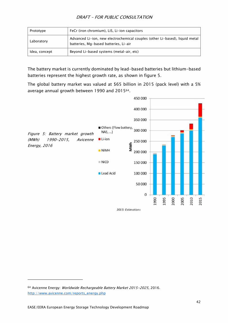
DRAFT – FOR PUBLIC CONSULTATION
42
EASE/EERA European Energy Storage Technology Development Roadmap
Prototype FeCr (iron chromium), LiS, Li-ion capacitors
Laboratory Advanced Li-ion, new electrochemical couples (other Li-based), liquid metal
batteries, Mg-based batteries, Li-air
Idea, concept Beyond Li-based systems (metal-air, etc)
The battery market is currently dominated by lead-based batteries but lithium-based
batteries represent the highest growth rate, as shown in figure 5.
The global battery market was valued at $65 billion in 2015 (pack level) with a 5%
average annual growth between 1990 and 201564.
Figure 5: Battery market growth
(MWh) 1990-2015, Avicenne
Energy, 2016
64 Avicenne Energy: Worldwide Rechargeable Battery Market 2015-2025, 2016.
http://www.avicenne.com/reports_energy.php

DRAFT – FOR PUBLIC CONSULTATION
43
EASE/EERA European Energy Storage Technology Development Roadmap
Energy storage represents a different market for batteries with a specific value chain,
as seen in the below figure:
Figure 6: compilation by EMIRI, EUROBAT, EASE, and Technofi, 2016
This complex value chain requires collaboration between five categories of suppliers
at global level:
Raw materials suppliers (metals, additives and solvents), which can be located
in large chemical companies
Advanced materials and component suppliers (anode material, cathode
material, electrolyte, separators, binders, additives, cell housing) which can be
located in large chemical companies or divisions of manufacturing companies
Cell manufacturers
Battery pack suppliers
Storage integrators which, when considering grid applications, are located in
each of major power system integrators
R&D efforts are important at all of these stages, not only at the electrochemical stage.
In particular, R&D efforts supporting developments in the system integration of
battery storage are particularly valuable for the European battery industry.
Batteries will require strong R&D efforts in order for them to be able to compete
against other flexibility solutions such as flexible generation, grid upgrade,
interconnections or demand response. Although some lithium-based solutions are
already available and are already marketed for some grid storage applications, a
significant decrease in the Levelised Cost of Stored Energy (LCOSE) is needed for the
battery storage market to continue its rapid growth.

DRAFT – FOR PUBLIC CONSULTATION
44
EASE/EERA European Energy Storage Technology Development Roadmap
Some battery technologies, such as Li-ion, are expected to benefit from the R&D and
industrial investments made for the automotive sector. The rapidly decreasing costs
for EV battery packs (as seen in figure 7) are expected to have an impact on the energy
storage batteries sector as a whole.
Figure 7: Cost estimates and future projections for electric vehicle battery packs, measured
in US $ per kilowatt hour of capacity. Each mark on the chart represents a documented
estimate reviewed by the study. Source: Nykvist et al. (2015)65
Applications
Electrochemical storage systems are considered one of the key energy storage
technologies enabling the transition from the current mostly centralised electricity
generation networks to distributed ones with increasing penetration of variable and
non-programmable renewable energy sources (e.g., wind and photovoltaic) and more
“intelligent” management of the energy flows (with smart grids and “prosumers”, i.e.
end-users with a more active role in the electricity market).
The different energy storage applications can be segmented according to the
discharge time, as shown in figure 8.
65 Björn Nykvist and Måns Nilsson: Rapidly falling costs of battery packs for electric vehicles, Nature
Climate Change 5, p 329–332, 2015.
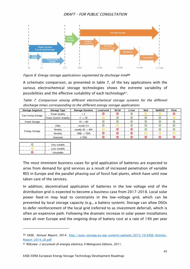
DRAFT – FOR PUBLIC CONSULTATION
45
EASE/EERA European Energy Storage Technology Development Roadmap
Figure 8: Energy storage applications segmented by discharge time66
A schematic comparison, as presented in table 7, of the key applications with the
various electrochemical storage technologies shows the extreme variability of
possibilities and the effective suitability of each technology67.
Table 7: Comparison among different electrochemical storage systems for the different
discharge times corresponding to the different energy storage applications
The most imminent business cases for grid application of batteries are expected to
arise from demand for grid services as a result of increased penetration of variable
RES in Europe and the parallel phasing out of fossil fuel plants, which have until now
taken care of the services.
In addition, decentralised application of batteries in the low voltage end of the
distribution grid is expected to become a business case from 2017–2018. Local solar
power feed-in may lead to constraints in the low-voltage grid, which can be
prevented by local storage capacity (e.g., a battery system). Storage can allow DSOs
to defer reinforcement of the local grid (referred to as investment deferral), which is
often an expensive path. Following the dramatic increase in solar power installations
seen all over Europe and the ongoing drop of battery cost at a rate of 14% per year
66 EASE: Annual Report, 2014. http://ease-storage.eu/wp-content/uploads/2015/10/EASE-Activity-
Report-2014_LR.pdf
67 RSEview: L’accumulo di energia elettrica, Il Melograno Editore, 2011.
Storage Segment Storage Type Storage Duration Lead-acid Ni-Cd Li-ion NaS NaNiCl2 Flow
Power Quality < 1' L L J K K L
Power System Stability 1' → 15' K J J J J K
Power Storage 15' → 60' J J J J J J
Daily usualy 6 h J K J J J J
Weekly usually 30 → 40h K L L J J J
Monthly 168h → 720h L L L K K K
Seasonal ≥ 720h L L L L L L
J Very suitable
K Less suitable
L Unsuitable
Fast Acting Storage
Energy Storage
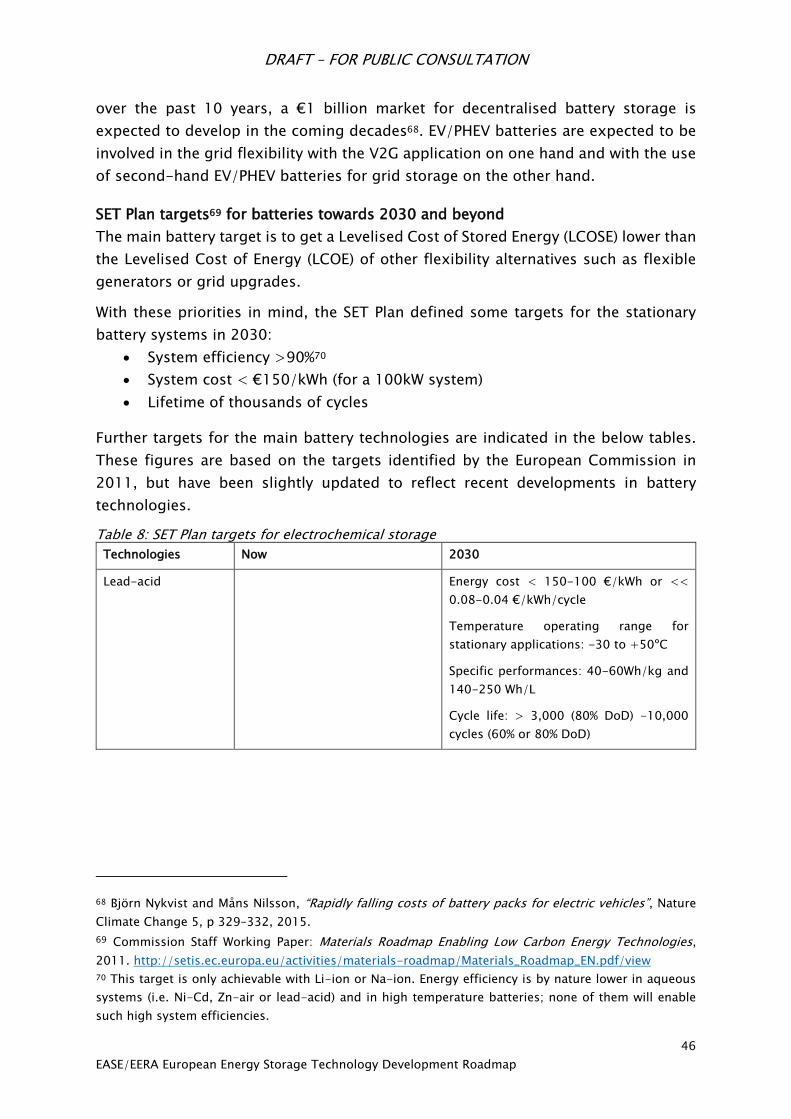
DRAFT – FOR PUBLIC CONSULTATION
46
EASE/EERA European Energy Storage Technology Development Roadmap
over the past 10 years, a €1 billion market for decentralised battery storage is
expected to develop in the coming decades68. EV/PHEV batteries are expected to be
involved in the grid flexibility with the V2G application on one hand and with the use
of second-hand EV/PHEV batteries for grid storage on the other hand.
SET Plan targets69 for batteries towards 2030 and beyond
The main battery target is to get a Levelised Cost of Stored Energy (LCOSE) lower than
the Levelised Cost of Energy (LCOE) of other flexibility alternatives such as flexible
generators or grid upgrades.
With these priorities in mind, the SET Plan defined some targets for the stationary
battery systems in 2030:
System efficiency >90%70
System cost < €150/kWh (for a 100kW system)
Lifetime of thousands of cycles
Further targets for the main battery technologies are indicated in the below tables.
These figures are based on the targets identified by the European Commission in
2011, but have been slightly updated to reflect recent developments in battery
technologies.
Table 8: SET Plan targets for electrochemical storage
Technologies Now 2030
Lead-acid Energy cost < 150-100 €/kWh or <<
0.08-0.04 €/kWh/cycle
Temperature operating range for
stationary applications: -30 to +50ºC
Specific performances: 40-60Wh/kg and
140-250 Wh/L
Cycle life: > 3,000 (80% DoD) -10,000
cycles (60% or 80% DoD)
68 Björn Nykvist and Måns Nilsson, “Rapidly falling costs of battery packs for electric vehicles”, Nature
Climate Change 5, p 329–332, 2015.
69 Commission Staff Working Paper: Materials Roadmap Enabling Low Carbon Energy Technologies,
2011. http://setis.ec.europa.eu/activities/materials-roadmap/Materials_Roadmap_EN.pdf/view
70 This target is only achievable with Li-ion or Na-ion. Energy efficiency is by nature lower in aqueous
systems (i.e. Ni-Cd, Zn-air or lead-acid) and in high temperature batteries; none of them will enable
such high system efficiencies.

DRAFT – FOR PUBLIC CONSULTATION
47
EASE/EERA European Energy Storage Technology Development Roadmap
Li-ion (cell level)
Specific energy:
Energy density:
Cost:
Power:
Life time
Safety:
274 Wh/kg 71
700 Wh/l
250 €/KWh
3 000 W/kg
5000 cycles (C anode)
High stability
320 Wh/kg
800 Wh/l
150 €/kWh
10 000 W/kg
10 000 cycles (C anode), 60,000 cycles
(Li-ion titanate)
No Hazard
Flow Batteries:
Energy cost
Power cost
120 €/kWh
250 €/kW
High temperature:
(Sodium-based)
Energy Cost
Cycle life cost:
X/kWh
3 000 €/kW
$0.04–$0.75/kWh/cycle
Y/kWh
1 500 €/kW
$0.01–$0.08/kWh/cycle
Na-Ion
Specific Energy
Energy cost
90 Wh/kg (Aquion)
S 250/kWh (Aquion)
110 Wh/kg
130 $/kWh max
Metal-air Systems:
Zn-Air:
Li-air:
$ 160/200/KWh for a
1MW/4MWH system (EOS)
700Wh/kg (Li air Polyplus)
150 cycles72
?
>500Wh/kg, 300-500€/kWh
3000 cycles
Li-S:
Specific Energy:
Energy cost
120 Wh/kg, 1 400 cycles at
system level (48V/3 kWh: Oxis) or
350 Wh/Kg, 100 cycles at cell
level (Oxis)
400 Wh/kg , 3000 cycles at cell level
150 €/kWh
71 Achieved for consumer cells (18650) with limited cycle life time. Industrial cells achieve about 170
Wh/kg today.
72 In air with 17% humidity. Source: J. Amici et al: O2 selective membranes based on a dextrin-
nanosponge (NS) in a PVDF-HFP polymer matrix for Li–air cells, Chem. Commun., 2016, 52.
DRAFT – FOR PUBLIC CONSULTATION
48
EASE/EERA European Energy Storage Technology Development Roadmap
When looking at the above targets, one should keep in mind that it can be difficult or
impossible to achieve all performance criteria for a given technology concurrently
(e.g. life time versus energy density). Furthermore, some performance parameters
strongly depend on use conditions (e.g. cycle life depending on frequency of fast
charge).
Gaps between targets and present performance
Lead-acid technology: there is a need to improve its cycle life time and operation
at partial state of charge without increasing investment costs (€/kWh).
High temperature battery technology (sodium based): it must simultaneously
improve its life time (cycle life time and calendar life time) and decrease its
investment costs (€/kW).
Li-ion technology: although Li-ion batteries are commercially available in large
systems and offer considerable advantages already today, there are still
significant potential for improvements both in performance and in cost. A further
reduction of LCOSE will broaden the spectrum of grid applications that are
becoming economically viable with storage. The decrease in LCOSE is expected to
be reached by improvements in production technology, value chain restructuring,
the use of low cost materials, the increase of the specific energy, and the increase
in life duration (cycle life and calendar life). Another possibility will be the use of
second hand batteries provided by the transport sector. A clearer standardisation
into three segments (power/hybridisation battery, lowest cost option, range
option) can be expected. Appreciable gains in terms of performance are expected
from all-solid-state batteries, including those still in early development stage.
Li-S technology: it must improve both its cycle and calendar life time, increase its
energy density using less electrolytes, and reduce its high level of self-discharge.
The use of metallic lithium as anode can lead to improvements in safety.
M-air technology: only Zn-air batteries are currently available for demonstration
purposes. This technology must improve its round-trip efficiency and its power-
to-energy ratio. Li-air are at prototype level and must improve their cycle life and
energy density (tested in air and not only in pure oxygen).
Na-ion technology: only Na-ion batteries based on a neutral pH aqueous based
electrolyte are available for demonstration purposes. No suitable cathode
materials exist today at industrial scale. This technology must improve its specific
energy, energy density, and power capability. Similarly to Li-ion batteries, solid-
state concepts should increase these values. Na-ion technology will also require
sufficient cost reductions in order to displace Li-ion.
Flow battery technology: the two key strengths of flow batteries for grid scale
storage are related to long lifetimes with a proven capability to operate over more

DRAFT – FOR PUBLIC CONSULTATION
49
EASE/EERA European Energy Storage Technology Development Roadmap
than ten thousand charges and the ability to decouple power and energy. This
offers flexibility for a wide range of applications requiring either high power or
high energy. However, key challenges in two main R&D areas should be addressed:
substantial cost reduction of the flow battery systems (membrane and materials),
better life time of the membrane, and possibly improvements in power and energy
density.
Research Priorities
The main priority for R&D efforts is to decrease the LCOSE of the batteries for each
relevant energy storage application or aggregate of relevant energy storage
applications. The following focus areas are proposed for research in electrochemical
energy storage:
1. Immediate priorities are improvements to the cycle life and overall calendar life
as well as the safety and the fast charging ability of all battery technologies
addressing the relevant degradation mechanisms.
2. Intensive research focused on materials and their processing (e.g. local tailoring
of materials properties or electrode architectures with thin film, plasma or laser
technology) for the most attractive battery technologies will be required for
substantial breakthroughs and increased applicability for batteries to grid
applications. Each technology has the potential for significant further technical
improvement, and all can provide distinctive and important functions to grid
operators. However, Li-ion technologies are particularly promising, and research
on Si-based and LTO-based anodes for their respective niches, as well as high
voltage cathodes, would be valuable areas of research.
3. It is essential to develop mechanical system designs with light structural materials,
as well as efficient and low cost thermal management systems. Battery operating
system weight and thermal management are important areas for system
improvements sometimes easier to achieve than electrochemical improvements.
4. Research should be directed both at improving performances at the battery cell
level, and battery system design level (connectors, battery management system,
interaction with the grid, etc.). Research on the chemistry itself has also high
potential as it has not been carried out sufficiently for these new functionalities.
Research should also focus on intelligent battery management, including the
electronics and systems for quality control and battery “smartness”.
5. Exploratory research, using for instance combinatorial materials approaches, is
strongly recommended on novel materials for completely new electrochemical
systems (e.g., metal-air, liquid batteries, all-solid-state batteries, Mg-based
batteries, organic batteries, fluoride-ion, chloride-ion, other conversion-based
systems, battery cells up to 5V) with the additional targets for the 2020-2030
DRAFT – FOR PUBLIC CONSULTATION
50
EASE/EERA European Energy Storage Technology Development Roadmap
period to further reduce the battery cost by more than 40%. Particular attention
should be paid to utilising raw materials which will not be foreseen as scarce or
environmentally problematic. In general, the targeted technical and economical
performances of the emerging electrochemical technologies may be estimated to
be in the Horizon 2020-2030: more than 500 Wh/kg, more than 3000 complete
charge/discharge cycles and a cell cost below 350 €/kWh.
6. Intensive research efforts should be carried out at the grid integration level in
order to decrease storage system costs and to facilitate the aggregation of
different applications.
7. There is also a need for intensive research on synthesis and new manufacturing
processes in order to decrease the battery cost at both the cell and system level.
8. Research and demonstration on the use of second hand batteries (mainly Li-ion
batteries) provided by the transport sector for stationary storage could yield
valuable insights into ageing processes and their correlation safety. Also, research
and demonstration is needed for the V2G concept, particularly with regards to the
impact of dual applications on battery life.
Recommendations for Research Funding, Infrastructure, and Incentives
A predominantly research-directed effort on improved or brand-new electrochemical
storage systems is required. Funding of at least 50-70 M€ per year would be
necessary to reach significant electrochemical improvements. The most effective
approach will be to focus on research yielding continuous improvements and cost
reductions. It will also be important to support research laboratories focused on basic
and applied materials research and electrochemical development, with advanced
research infrastructure and modelling tools, complete investigation of safety and
degradation mechanisms, up to complete engineering and full-scale demonstration.
Moreover a well-coordinated European network of joint research between industry,
academia, and large research centres on electrochemical energy storage should be
established, as it is urgently needed to reach a low-carbon future, cement European
leadership, and support the creation of new jobs.

DRAFT – FOR PUBLIC CONSULTATION
51
EASE/EERA European Energy Storage Technology Development Roadmap
6.3 Electrical Energy Storage
Supercapacitors
Introduction
Electrochemical capacitors (ECs), also referred to as “supercapacitors” or
“ultracapacitors,” store electrical charge in an electric double layer at the interface
between a high-surface-area carbon electrode and a liquid electrolyte. Consequently,
they are also referred to as electric double layer capacitors (EDLC). Since this
mechanism is highly reversible, ECs, exactly like conventional capacitors, can be
charged and discharged at high power rates thousands of times with low capacitance
fade. The electrode surface area in capacitors determines the capacitance and thus,
the energy storage capability of the device. The amount of energy stored by ECs is
very large compared to conventional capacitors because of the use of a porous
carbon-based electrode material of high surface area.
While supercapacitors have very high specific power (10-20kW/kg) relative to
batteries, they have a low specific and volumetric energy density (<8Wh/kg). One
related chemistry that seeks to improve the energy density of supercapacitors while
maintaining high power capability, cyclability, and lifetime is the lithium-ion
capacitor (LCAP). The LCAP features a positive electrode similar to a supercapacitor
electrode, while the negative electrode contains partially intercalated lithium. State-
of-the-art technology indicates a two- to three-fold increase in energy density
relative to a supercapacitor, with a similar discharge profile and cycling capability.
Maturity of technology
Supercapacitors have a short history dating back to their first discovery in 1957.
Niche uses have been seen since the early 1980s and a broader use of ECs has
accelerated over the last 15 years in particular. Supercapacitors are now widely
commercialised in hybrid bus, rail, and automotive applications, as well as back-up
power applications such as wind pitch control systems and uninterrupted power
supplies. They are in the demonstration/piloting phase for grid energy storage
systems as a stand-alone technology or hybridised with a second, low-cost high
energy density technology, such as flow batteries and high energy Li-ion batteries.
LCAP technology has been in development for nearly a decade and piloting is
anticipated over the next several years in both transportation and grid energy storage
applications.

DRAFT – FOR PUBLIC CONSULTATION
52
EASE/EERA European Energy Storage Technology Development Roadmap
Applications
ECs are very suitable for high-power applications and are therefore witnessing
growing interest from electric utilities, which are looking to these devices for
performance improvement and reliability in a variety of areas, with much higher
power levels and with transmission voltages up to 12kV and distribution voltages up
to 1500V. The key features of ECs are extremely appealing for a variety of
applications in electricity grids: fast response time in milliseconds, high energy
efficiency (more than 95%), high power density, and long calendar and cycle life. A
number of valuable functions can be performed by EC devices in electric grids, such
as:
1. Transmission line stability: the stability of a transmission system can be
improved by adding energy storage. This serves to dampen oscillation through
the successive generation and absorption of real (as opposed to reactive)
power. There is also transient stability – the stability required after a utility
event (loss of substation or major line). During a transient event, achieving
stability requires a substantial capability to absorb energy quickly. This is
somewhat analogous to “dynamic braking” because generator turbines must
be slowed. A typical specification is 100 MW with 500 MJ (< 5 s).
2. Spinning reserve: this is the generation capacity that a utility holds in reserve
to prevent service interruptions if a generator fails. An ultracapacitor system
can be built to supply power during the interruption, until quick-start diesels
begin to supply power. A typical specification is 20MW to 100MW and 300 MJ
to 1500 MJ.
3. Area and frequency control: the mismatch between electrical energy
production and energy consumption (including losses) appears as a frequency
variation. EC systems, thanks to their fast response time, would be
considerably more effective than a generating plant in supplying frequency
regulation. A system based on EC can absorb or supply energy as required,
freeing other generation sources from frequency regulation or tie-line control
duties. A typical specification is 100 MW to 1000 MW and 0.1 MWh to 10 MWh.
4. Renewables intermittency smoothing: power output from a renewable source
such as solar can fluctuate by over 50% on a second-by-second basis.
Ultracapacitors can rapidly inject power into a grid or microgrid to stabilise
power output. A typical specification is 1- 500 MW and 0.1 to 5 MWh.

DRAFT – FOR PUBLIC CONSULTATION
53
EASE/EERA European Energy Storage Technology Development Roadmap
SET-Plan Targets73
Table 9: SET Plan targets for supercapacitor* technologies towards 2030 and beyond
Current performance Target 2020-2025 Target 2030 Target 2050
48 Wh/kg EDLCs
1015 Wh/kg for Li-ion
capacitors
10-20kW/kg (1-5s)
(500k – 1M cycles
depending on systems)
Low T °C (-20°C)
High T ( 65°C)
>20-30Wh/kg
Voltage stability ca.
3.54V
ca. 0.10.5 c€/F
Low T °C (-40°C)
High T ( 85°C)
50Wh/kg
Voltage stability
ca. > 4V
ca. 0.1 c€/F
Electrolyte stability ca.
4.5-5V
ca. 3000m2g active
area
ca. 600F/g
Energy close to power
batteries (50Wh/kg)
*Supercapacitors (EDLC, Li-ion capacitors, Pseudo capacitors, hybrid, symmetric and asymmetric systems)
Table 10: Economic SET Plan targets for supercapacitor technology towards 2030
Current performance Target 2020-2030 * Target 2050
>7Wh/kg
10-20kW/kg (1-5s)
ca. 1500-2000m2g
>10000 500,000 -
1,000,000 cycles
(depending on
application)
Low °C (-40°C)
High T ( 65°C)
€0,3/W (cell basis)
10-30 Wh/kg
15-25kW/kg (1-5s)
500,000 - 1,000,000
cycles (depending on
application)
Low °C (-40°C)
High T ( 85°C)
€0,2/W (cell basis)
Electrolyte stability ca. 4.5-5V
ca. 3000m2g active area
ca. 600F/g
Energy close to power
batteries (50Wh/kg)
€0,05/W (cell basis)
Gaps between targets and present performance
ECs are interesting for their capacity to store very high power in a small volume and
weight with high stability over a long period time. The storage system round-trip
efficiency is extremely high, at around 95%.
Driven by economies of scale and advancements in manufacturing, the cost of
supercapacitors has decreased dramatically for their deployment in grid energy
storage systems. At present, fully installed costs are estimated to be $1000/kW and
are expected to decrease to $517/kW by 202174. Given this customer value
improvement and the ability to pair with batteries to “stack” grid services and improve
battery lifetime, supercapacitors are now being piloted in systems across the globe.
73 Commission Staff Working Paper: Materials Roadmap Enabling Low Carbon Energy Technologies,
2011. http://setis.ec.europa.eu/activities/materials-roadmap/Materials_Roadmap_EN.pdf/view
74 Navigant Research, May 2016
DRAFT – FOR PUBLIC CONSULTATION
54
EASE/EERA European Energy Storage Technology Development Roadmap
Research Priorities
The following topics are key research priorities for ECs over the next decades:
1. Finding electrolytes capable of voltages beyond 3.0 V, preferably with less
toxicity. One route to achieve this will be the development of ionic liquids and
new conducting salts for higher voltage ranges with wide operational
temperature ranges and high conductivity. Ionic liquids-solvent mixtures with
high voltage solvents as developed in Li ion batteries (additives/new solvents).
2. Proof of concept of asymmetric LCAP systems: improve life cycle and improve
symmetry of charge-discharge rates to achieve 20-30 Wh/kg in synergy with
high power Li-ion batteries; proof of concept of ceramic EC with dielectric or
insulator with very high permittivity.
3. Basic and applied research on aqueous hybrid systems for very low cost and
low environmental impact using activated carbons.
4. There are extraordinary opportunities that may come from the use of pseudo
capacitive charge storage materials, which can lead to much higher levels of
charge storage than ECs because of redox reactions. Improved understanding
of charge transfer processes in pseudo capacitance is a critical step that will
lead to the design of new materials and multifunctional architectures offering
substantially higher energy density and at high discharge/charge rates. Novel
transition metal oxides of lower cost, eco-friendly (e.g. MnO2) and better
performances need to be explored for EC applications because of their layered
structure and ability to adopt a wide variety of oxidation states.
Further interesting research issues are to reduce component and finished electrode
material manufacturing costs and to increase the capacitance of electrodes by
enlarging the surface area and tailoring the pore size and shape. Figure 99
summarises the roadmap of ECs with projections towards 2030, in which are
evidenced the future visions on development of new high performance materials for
electrodes and electrolytes.

DRAFT – FOR PUBLIC CONSULTATION
55
EASE/EERA European Energy Storage Technology Development Roadmap
Figure 9: Tentative Roadmap for supercapacitors with vision to 2030 (prepared by CNR-ITAE
from75).
Recommendations for Research Funding, Infrastructure, and Incentives
A predominantly research-directed effort on new supercapacitive systems is
required. Funding in the range of at least €10-15 million per year would be necessary
to reach significant EC improvements. As indicated, this effort is anticipated in
research laboratories, while European industry is expected to contribute with only a
minor part. In particular, research should focus on (large-scale) demonstration
projects because for grid applications the most common use of supercapacitors in
Uninterruptible Power Systems (UPS) has been complemented by few demonstration
projects.
Research infrastructure should enable clustering of research groups in Europe as well
as organisation and effective distribution of efforts between electrochemical research
centres in Europe. The full benefit of European electrochemical storage potential can
only be reached by integrating and complementing current national and European
research programs and projects for optimal utilisation of resources and efforts, as is
underway in EERA collaborations. A stronger and more intelligent coordination of
resources (both central EU resources and national resources in member states) will
improve the overall outcome to the benefit of the European population.
75 P. Staiti, A. Arenillas, F. Lufrano, J.A. Menendez, J. Power Sources 214 (2012) 137; Q. Gao, et al., Energy
Environ. Sci. 5 (2012) 9611 ; S. Makino, et al., RSC Advances, 2 (2012) 12144 ; K. Naoi, et al. Energy
Environ. Sci. 5 (2012) 9363.
Symmetric organic high power
Material
Electrodes
Material
Electrolytes
R & D
Devices
Configuration
High
energy,
Long life
High
power,
Low cost
Safety
Activated carbon - high surface area 3000 m2/g
AC, CNFs, Carbon gels, graphene, 2D/3D materials, CDCs, hard & template carbons
MnO2, RuO2, MXenes, ECPs, NiO, Ni(OH)2, Nb2O5, Co3O4 materials
T0 + 4 T0 + 12T0 + 8T0 T0 + 16
Ionic liquids & conducting salts (ILs) 3.0 3.2 V PILs, ILs, salts 3.5 4.0 V
Aqueous/polymer salts 1.5 2.0 V polymer/salts 2.2 3.0 V
Organic 2.7 2.85 V 3.0 3.3 V 3.2 3.6 V
Symmetric organic high energy
Asymmetric for high power and high energy – eco-friendly low costs
Hybrid Li-ion caps 3.5 4.0V hybrid LiC 4 5V
Symmetric organic high energy
Asymmetric aqueous/organic for high energy
Hybrid for high voltage and high energy
Asymmetric aqueous/organic for high power
Hybrid for high voltage, power and high energy
Energy ca. 30-50 Wh kg-1
Power ca. 10-30 kW kg-1
HyECs > 200.000 cycles
Low self-discharge
Low cost
Safety
Eco-friendly
DRAFT – FOR PUBLIC CONSULTATION
56
EASE/EERA European Energy Storage Technology Development Roadmap
Superconducting Magnetic Energy Storage (SMES)
Introduction
SMES has been of scientific interest for years76,77,78,79,80 and still requires a
considerable development effort to demonstrate its economic potential. Long-term
rather basic R&D efforts are required, but these will likely pay off since the technology
may hold considerable potential.
In SMES systems, the energy is stored in the magnetic field of superconducting coils,
thereby exploiting the ultra-low losses of superconductors which allows a very fast
delivery of high power (ms) at high cycle efficiency (>95 %), even if the cooling is
accounted for. Other key issues are a high robustness, full charging and discharging,
and a long lifetime with a virtually unlimited number of cycles.
To date, the cost for the cryogenic infrastructure has prevented a broader utilisation
of SMES, but the new superconductors which can be operated at higher temperatures,
the so called High-Temperature Superconductors (HTS), now provide a concrete
perspective for new engineering designs. In addition, a combination of SMES with
large-scale storage systems (such as electrochemical storage systems, Compressed
Air Energy Storage (CAES) or cryogenic storage), can provide the robustness, high-
speed, high peak power, high efficiency, and long life characteristics for achieving a
complete storage system capable of complementing the lower speed response and
protecting against sudden power demands. The high flexibility of such a robust,
powerful, fast, and efficient buffer allows a better dimensioning of the long-term
energy storage systems. Typical applications could be found at the customer level
76 Boenig H.J., Hauer J.F., Commisioning Tests of the Bonneville Power Administration 30 MJ
Superconducting Magnetic Energy Storage Unit, IEEE Trans. Power Apparatus and Systems, vol. PAS-104,
No 2, February 1985, DOI: 10.1109/TPAS.1985.319044
77 P. Esteban ; A. Bautista ; J.L. Gutierrez-Iglesias ; J.M. Rodriguez ; E. Urretavizcaya, SMES systems
applications to improve quality service, Electricity Distribution. Part 1: Contributions. CIRED. 14th
International Conference and Exhibition on (IEE Conf. Publ. No. 438), DOI: 10.1049/cp:19970481.
78 A. Bautista ; P. Esteban ; L. Garcia-Tabares ; C. Peon ; E. Martinez ; J. Sese ; A. Camon ; C. Rillo ; R.
Iturbe, Design, manufacturing and cold test of a superconducting coil and its cryostat for SMES
applications, IEEE Transactions on Applied Superconductivity Volume: 7, Issue: 2, June 1997, DOI:
10.1109/77.614637.
79 H. Salbert ; D. Krischel ; A. Hobl ; M. Schillo ; N. Blacha ; A. Tromm ; W. Roesgen, 2 MJ SMES for an
uninterruptible power supply, IEEE Transactions on Applied Superconductivity, Volume: 10, Issue: 1,
March 2000 , DOI: 10.1109/77.828346
80 T. Katagiri ; H. Nakabayashi ; Y. Nijo ; T. Tamada ; T. Noda ; N. Hirano ; T. Nagata ; S. Nagaya ; M.
Yamane ; Y. Ishii ; T. Nitta, Field Test Result of 10MVA/20MJ SMES for Load Fluctuation Compensation,
IEEE Transactions on Applied Superconductivity, Volume: 19, Issue: 3, June 2009, DOI:
10.1109/TASC.2009.2018479.
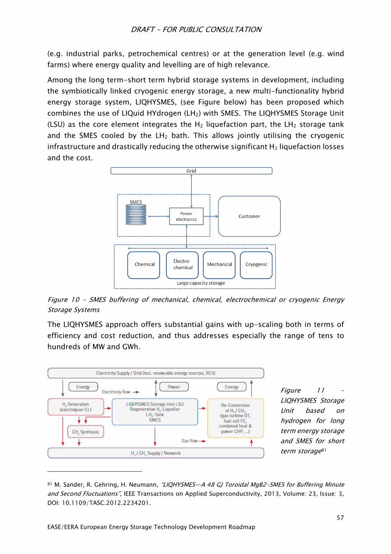
DRAFT – FOR PUBLIC CONSULTATION
57
EASE/EERA European Energy Storage Technology Development Roadmap
(e.g. industrial parks, petrochemical centres) or at the generation level (e.g. wind
farms) where energy quality and levelling are of high relevance.
Among the long term-short term hybrid storage systems in development, including
the symbiotically linked cryogenic energy storage, a new multi-functionality hybrid
energy storage system, LIQHYSMES, (see Figure below) has been proposed which
combines the use of LIQuid HYdrogen (LH2) with SMES. The LIQHYSMES Storage Unit
(LSU) as the core element integrates the H2 liquefaction part, the LH2 storage tank
and the SMES cooled by the LH2 bath. This allows jointly utilising the cryogenic
infrastructure and drastically reducing the otherwise significant H2 liquefaction losses
and the cost.
Figure 10 - SMES buffering of mechanical, chemical, electrochemical or cryogenic Energy
Storage Systems
The LIQHYSMES approach offers substantial gains with up-scaling both in terms of
efficiency and cost reduction, and thus addresses especially the range of tens to
hundreds of MW and GWh.
Figure 11 -
LIQHYSMES Storage
Unit based on
hydrogen for long
term energy storage
and SMES for short
term storage81
81 M. Sander, R. Gehring, H. Neumann, “LIQHYSMES—A 48 GJ Toroidal MgB2-SMES for Buffering Minute
and Second Fluctuations”, IEEE Transactions on Applied Superconductivity, 2013, Volume: 23, Issue: 3,
DOI: 10.1109/TASC.2012.2234201.
DRAFT – FOR PUBLIC CONSULTATION
58
EASE/EERA European Energy Storage Technology Development Roadmap
Maturity of technology
SMES based on Low Temperature Superconductors (LTS) have been built up to a power
of 10 MW and a capacity of 20 MWs82. Qualified LTS SMES systems have proven in
several long-term field tests that they can fulfil all technical requirements. Several
companies have started to offer LTS SMES commercially. Since 2011, three LTS SMES
units with deliverable power of 10 MW have been in operation in Japan for bridging
instantaneous voltage dips of critical industrial customers.83 Due to the relatively high
system cost, however, LTS SMES has not been able to find a wider market up to now.
The maturity of LTS SMES has reached Technology Readiness Level (TRL) 8, meaning
that several systems were completed and qualified through testing and
demonstration.
The discovery of high-temperature superconducting (HTS) materials and the ongoing
development of the 2G superconducting wires, known as coated conductors, open a
window for a new class of HTS SMES to work at higher temperatures (up to 50 K),
higher magnetic flux densities (up to 20 T), and even higher efficiencies. The success
in the production of HTS wires and tapes with an increasing number of producers and
a decreasing cost performance ratio envisages that a modular MW class HTS SMES
could be an attractive device. To date, 2.5 MW HTS SMES have been designed84 which
means that a TRL of 5 to 6 has been reached. Further improvements towards larger
magnetic flux density systems, coil manufacturing, HTS winding cable, and cooling
simplification are ongoing.
A hybrid energy storage based on a SMES in combination with other storage
technologies has been studied85,86 for different combinations but not more than a
proof of concept and small laboratory experiments on a TRL of 3 have been
82 T. Katagiri, H. Nakabayashi, Y. Nijo, T. Tamada, T. Noda, N. Hirano, T. Nagata, S. Nagaya, M. Yamane,
Y. Ishii, and T. Nitta, “Field Test Result of 10MVA/20MJ SMES for Load Fluctuation Compensation”, IEEE
Transactions on Applied Superconductivity, 2009, Volume: 19, Issue: 3, Pages: 1993 - 1998, DOI:
10.1109/TASC.2009.2018479. 83 Shigeo Nagaya, Naoki Hirano, Toshio Katagiri, Tsutomu Tamada, Koji Shikimachi, Yu Iwatani, Fusao
Saito, Yusuke Ishii, The state of the art of the development of SMES for bridging instantaneous voltage
dips in Japan, Cryogenics, Volume 52, Issue 12, December 2012, Pages 708-712 84 Lee, S; Yi, KP ; Park, SH ; Lee, JK ; Kim, WS; Park, C; Bae, JH; Seong, KC; Park, I; Choi, et al, Design of
HTS Toroidal Magnets for a 5 MJ SMES, IEEE Transactions on Applied Superconductivity, Volume: 22,
Issue 3, DOI: 10.1109/TASC.2011.2175871 85 Li, J., Zhang, M., Yang, Q., Zhang, Z. and Yuan, W., 2016. SMES/battery hybrid energy storage system
for electric buses. IEEE Transactions on Applied Superconductivity, 26 (4), 7403905, DOI:
10.1109/TASC.2016.2527730
86 Jianwei Li , Anthony M. Gee, Min Zhang, Weijia Yuan, Analysis of battery lifetime extension in a SMES-
battery hybrid energy storage system using a novel battery lifetime model, Energy 86 (2015) 175-185,
DOI: 10.1016/j.energy.2015.03.132.

DRAFT – FOR PUBLIC CONSULTATION
59
EASE/EERA European Energy Storage Technology Development Roadmap
performed. Nevertheless, this seems attractive because it combines the benefits of
SMES with a large storage capacity.
Applications
Since SMES provide high power in a short time and are rather limited in their energy
storage capacity, they are suitable to enable pulsed power supply (e.g. accelerators),
to improve power quality at the customer or generator side, to contribute to voltage
control and reactive power compensation, to improve transient stability, and to
provide Uninterruptable Power Supply (UPS). Given its ability to withstand a practically
unlimited number of cycles, SMES is also suitable where fast and continuous
charge/discharge operation is required.
SMES plants do not depend on specific geological formations, they can be positioned
everywhere, and consequently markets should be addressable everywhere in the
world where these applications are needed.
Highly industrialised regions characterised by a high level of digitisation and
particular needs for high quality supply would then particularly benefit from the
ancillary services of the SMES. Potentially attractive locations in the electricity network
might be those where the SMES plants can be combined with other existing or
foreseen grid components, e.g. with reactive power control, AC-DC / DC-AC
conversion, transformers or circuit breakers.
Hybrid energy storage systems, consisting of SMES in combination with
electrochemical energy storage, can be attractive for providing both high power and
high energy capacity with extended lifetime and reduced overall costs. Potentially
attractive locations for a LIQHYSMES in a future H2 supply network might be those
where the LIQHYSMES plant can be combined with the production, storage, and
distribution of H2.
SET-Plan Targets
The SET Plan targets taken for the material development roadmap are given in table
11. Due to the rapid development of 2G HTS wires and tapes, these targets seem
outdated. Therefore, new targets for SMES materials, SMES technology, and SMES
systems are proposed in table 12.
Table 11 - Targets for SMES materials towards 2030 and beyond87
Current performance Target 2020-2030 Target 2050
Highly efficient >95 % Increasing critical T° of the
superconductors
Cost reduction >5-10%
ca. 100 €/kW (200€/kWh)
87 Commission Staff Working Paper: Materials Roadmap Enabling Low Carbon Energy Technologies,
2011. http://setis.ec.europa.eu/activities/materials-roadmap/Materials_Roadmap_EN.pdf/view

DRAFT – FOR PUBLIC CONSULTATION
60
EASE/EERA European Energy Storage Technology Development Roadmap
For short duration storage
(electricity stored in
magnetic field)
Superconducting coil
cooled below its critical T°
Second HTS generation:
>current density at high
magnetic field (i.e. >10m; >50
A)
Enhance performances at high
magnetic fields and reduce the
cost of YBCO coated
conductors
Table 12: Targets for SMES materials, technology and systems towards 2030 and beyond
Current performance Target 2020-2030 Target 2050
Highly efficient >95 %
For short duration storage
(electricity stored in
magnetic field)
Superconducting coil
cooled below its critical T°
Enhance performance and
decrease cost of MgB2 and 2 G
wires and tapes by a factor of
five
Standardise SMES technology
(cryostat, current leads,
cooling)
Improve the multi-physics
designing tools
Improve electronic control and
coil protection
Demonstrate HTS SMES in
hybrid or stand-alone
applications
Enhance performance and
decrease cost of MgB2 and 2 G
wires and tapes by a factor of
ten
Reduce cost and loss of SMES
technology (cryostat, current
leads, cooling) by a factor of
two
Apply SMES in commercial
applications
Gaps between targets and present performance
Challenges exist both in the field of new superconducting materials and adapted
novel designs and systems essentially based on modularity. The main gap is between
the present and envisaged cost/performance ratio of the superconductors and the
economy and maintenance of the cooling systems. The gap in the cost/performance
ratio of the superconductor can be closed by further R&D resulting in increased wire
performance and by introducing industrial production methods to further reduce the
wire cost. A further gap is that HTS SMES have not proven operation in long-term
field tests where it can be demonstrated that all user requirements can be fulfilled.
Hybridation with external cryogen sources should be complemented with cooling
machines able to work between the intermediate temperature of industrial liquid
cryogenic gases as LN2 or LCH4 and the superconducting requirements. Enhancing
the power of the existing low temperature rejection cryocoolers to the level of 100's
of W is needed for filling the gap for this type of machines, as they allow for greatly
increasing the cooling efficiency and capacity and while strongly diminishing the
required power.

DRAFT – FOR PUBLIC CONSULTATION
61
EASE/EERA European Energy Storage Technology Development Roadmap
Research Priorities
To achieve the SMES targets given in table 12, R&D efforts are required in the
following areas:
1. Improve critical material properties of HTS conductors and MgB2 tapes. This
includes higher in-field current densities, lower AC and ramping losses,
optimised wire architectures, longer lengths of high-quality, high-amperage
conductors, and cost reduction.
2. Develop SMES related system technology with a focus on new concepts in
magnet design, standardised components for cooling systems, cryostats, and
low loss current leads and power electronics.
3. Develop robust and self-stabilised HTS SMES magnets including high
performance electrical insulation with low-cost manufacturing and winding
methods. Modular approaches and methods for up-scaling have to be taken
into account.
4. Demonstrate HTS SMES system performance in attractive applications with
long-term field tests. Business cases need to be further developed and first
niche markets need to be addressed.
5. Develop low temperature heat rejection cryocoolers for working between the
interval 120-30K with cooling power in the range of 100's of W, able to work
with cryogens at 120K or 77K as high temperature, allowing so the use of
LCH4, LN2 or LO2 as the first cooling step.
6. Explore the opportunities of hybrid SMES systems at different TRLs depending
on the maturity of the hybrid system. This could range from system studies up
to first demonstrations.
SMES Recommendations for Research Funding, Infrastructure, and Incentives
Research funding should be focused on closing gaps towards commercialisation and
on the research priorities listed above. As an example, improving the cost-
performance ratio of HTS material would improve the economic viability of SMES and
support the fast rising commercialisation of HTS materials. It is also important to
demonstrate SMES performance in lighthouse demonstration applications. This could
be for example in a large scale hybrid energy storage demonstrator. Synergies can
be exploited by using existing energy infrastructure to integrate a SMES
demonstration system like the Energy Lab2.0 at KIT or comparable infrastructure.
Research infrastructure should be expanded and further supported and should
enable clustering of research groups in Europe. Furthermore, an effective distribution
of efforts between SMES research centres in Europe should be supported, as well as
networking between the different disciplines.

DRAFT – FOR PUBLIC CONSULTATION
62
EASE/EERA European Energy Storage Technology Development Roadmap
DRAFT – FOR PUBLIC CONSULTATION
63
EASE/EERA European Energy Storage Technology Development Roadmap
6.4 Mechanical Energy Storage
Compressed Air Energy Storage
Introduction
Compressed Air Energy Storage (CAES) refers to a process in which energy is stored
in the form of high pressure compressed air. A CAES system can be built to have
power scales from a few kilowatts to over a few hundred megawatts and energy
charge and discharge durations from a few minutes to a few days with moderate
response time and good partial-load performance. Any CAES installation refers to the
establishment of a system integrating different interacting components, devices, and
processes. The common components of a CAES system must include compressors,
expanders, and an air storage reservoir. The rest of the system components depend
on the system structure and operation principles.
Successful CAES implementation derives from the mid-20th century. In 1949, S. Laval
obtained a patent on using air to store power inside an underground air-storage
cavern, which marked a new era of CAES applications88. The world’s first utility-scale
CAES plant was installed and commissioned to operation by “Asea Brown Boveri (ABB)”
at Huntorf, Germany, in 197889. It has a rated power generation of 290 MW90. As an
available option for peak load shifting in power grid operation and due to its relatively
low cost compared to oil and gas prices through the 1980s to 1990s, CAES
technology development and its industrial applications have remained attractive. In
1991, another large-scale CAES plant commenced operation in McIntosh, Alabama,
US91. The 110 MW plant, with a storage capacity of 2,700 MWh, is capable of
continuously delivering its full power output for up to 26 hours. The plant is used to
store off-peak power, generate peak power, and provide spinning reserves.92 The
common feature of these two CAES plants is that they all involve burning a fossil fuel
– natural gas – in their electricity generation process.
88 B. J. Davidson, et al., “Large-scale electrical energy storage”, Physical Science, Measurement and
Instrumentation, Management and Education Reviews, IEE Proceedings A, vol. 127, no. 6, pp. 345–385,
1980.
89 B. J. Davidson, et al., “Large-scale electrical energy storage”
90 Ibid.
S. Succar, R.H. Williams, “Compressed air energy storage: theory, resources, and applications for wind
power”, technical report, Energy Systems Analysis Group, Princeton Environmental Institute, Princeton
University, 2008.
91 Ibid.
92 S. Succar, R.H. Williams, “Compressed air energy storage: theory, resources, and applications for wind
power” H. Chen, T. N. Cong, W. Yang, C. Tan, Y. Li, and Y. Ding, “Progress in electrical energy storage
systems: A critical review”, Progress in Natural Science, vol. 19, no. 3, pp. 291–312, 2009.
DRAFT – FOR PUBLIC CONSULTATION
64
EASE/EERA European Energy Storage Technology Development Roadmap
Maturity of technology
The Huntorf and McIntosh CAES power plants demonstrate the maturity of the first
and second generation CAES technology. The current development focuses on the
third generation CAES technology which aims to avoid involving fossil fuel by using
the heat generated through the compressing process93.
In 2010, RWE Power, General Electric, Züblin and the German Aerospace Centre (DLR)
started working on the world’s first large-scale Advanced Adiabatic (AA-CAES)
demonstration plant project, in which the heat generated in the compression stage is
stored in a thermal storage medium and used at the expansion process94. However,
this project was put on hold due to the lack of clarity about its economic and business
viability. Meanwhile, some R&D work in small-scale CAES has attempted to use CAES
to replace chemical batteries in some applications. US-based LightSail Energy Ltd.
patented and developed a CAES technology which came very close to achieving
isothermal compression and expansion (I-CAES) and which captures the heat from
the compression process by spraying water (with water drop sizes at the nano-scale)
for efficient heat absorption and storage. The stored heat is then added to the
compressed air during expansion using the same technology95.
A number of demonstration projects are currently on-going, indicating that the
technology for CAES with no fossil fuel is available. However, widespread deployment
requires market maturity and improvement in round trip efficiency.
Applications
In addition to the existing uses of CAES in Huntorf and Alabama, CAES can also
provide a wide range of attractive system services owing primarily to the impressive
ramp rates associated with the technology. CAES is capable of providing system
services such as, but not limited to, inertial response (in both compression and
expansion), operating reserve (primary, secondary and tertiary), fast frequency
response, fast post fault active power recovery, dynamic reactive response, and
steady state reactive power. CAES’ ability to provide such services will be a key
enabler for permitting higher levels of renewable energy and reduce wind power
curtailment while maintaining power system stability. A wide range of applications of
CAES is outlined in Table 13.
93 X. Luo, J. Wang, M. Dooner, J. Clarke and C. Krupke, “Overview of current development in compressed
air energy storage technology”, Energy Procedia, Vol. 62. pp.603-611, 2014. 94 RWE power, ADELE – Adiabatic compressed-air energy storage (CAES) for electricity supply, ADELE
Brochure, 2016. https://www.rwe.com/web/cms/mediablob/en/391748/data/364260/1/rwe-power-
ag/innovations/Brochure-ADELE.pdf
95 Lightsail Energy Ltd, 2016. http://www.lightsail.com

DRAFT – FOR PUBLIC CONSULTATION
65
EASE/EERA European Energy Storage Technology Development Roadmap
Table 13 Application potentials of CAES related technology96
96 X. Luo, J. Wang, “Overview of the current development on compressed air energy storage”, EERA
Report, 2016. http://integratedenergystorage.org. Not all characteristics outlined in this reference have
been included in the table. These are not the only characteristics CAES is capable of providing, as the
characteristics are dependent on the system operators’ requirements. Examples have been added to the
table.
Application
area
Characteristics
( [18, 50, 61 ~ 65])
Suitable or potential CAES related
technology
Power quality
<1MW, response time (milliseconds,
<1/4 cycle), discharge duration
(milliseconds to seconds)
Hybrid systems with small-scale
CAES and battery or supercapacitor
or other EES technologies with fast
response
Energy
management
Large-scale (>100 MW),
medium/small-scale (<100 MW),
response time (minutes), discharge
duration (up to days)
Large-scale energy management
(large-scale CAES); Small-scale
energy management (small-scale
CAES, LAES)
Renewable
back-up power
100 kW-40 MW, response time
(seconds to minutes), discharge
duration (up to days)*
Multi-scale CAES, hybrid systems
with CAES and capacitor or others
with fast response may need,
possible LAES
Emergency
back-up power
Up to 1 MW, response time
(milliseconds to minutes),
discharge duration (up to ~24 hours)*
Possible small-scale CAES, hybrid
systems with small-scale CAES and
other technologies with fast
response
Time shifting
1 MW-100 MW and even more,
response time (minutes), discharge
duration (3-12 hours)
Multi-scale CAES and LAES
Peak shaving
100 kW-100 MW and even more,
response time (minutes), discharge
duration (hour level, <10hours)
Multi-scale CAES and LAES
Load levelling
up to several hundreds of MW,
response time (minutes), discharge
duration (up to ~ 12hours and even
more)
Multi-scale CAES, possible LAES
Black Start Up to rated output (depending on
stored energy) response time minutes
Multi- scale CAES
Inertial
Response
Provided in both compression and
expansion
Multi- scale CAES
Frequency
Response
XX MW – XX MW, range dependent on
system operator response
requirements
Multi- scale CAES
DRAFT – FOR PUBLIC CONSULTATION
66
EASE/EERA European Energy Storage Technology Development Roadmap
*Note that the limits can vary significantly depending on individual system operators’ reserve response times and
requirements.
SET-Plan targets
Table 14 lists the theoretically highest achievable efficiency for all the major
segments in a CAES system. From the table, it can be seen that the highest efficiency
that can be achieved theoretically is 81.9% to date.
Table 14. The theoretical values of the maximum energy efficiency
Efficiency System
Efficiency
Compression
Efficiency
Heat
storage
Efficiency
Cold
storage
efficiency
Storage
efficiency
Expansion
Efficiency
Theoretical
value
81.9% 91% 99% 99% 99.8% 92%
The target should be to achieve the following efficiency by 2030:
2016 - 2020 2020 – 2030
Achieving system efficiency of 60 – 65% Achieving system efficiency around 70%
Gaps between targets and present performance
As described above, the main weakness of CAES is its relatively low energy efficiency.
From the current large scale CAES (> 1 MW) reported, the best round-trip efficiency
achieved is around 53%. The main target for CAES technology development is to
improve the CAES system efficiency to reduce the gap between the practical system
efficiency and the theoretically achievable efficiency.
Research Priorities
To further the development of CAES technology, the following research challenges
need to be addressed, in the order of priority from high to low:
1. Innovation in turbo machinery design and manufacturing: technical
innovations and technology breakthroughs are essential, especially for high-
pressure compressor and turbine technologies, such as developing improved
sealing methods for compression and expansion machinery to suppress
internal leakage and discovering approaches to minimise losses associated
with secondary flows in compressors and turbines.
Reactive Power
Response
XX MVar – XX MVar, range dependent
on system operator response
requirements
Multi- scale CAES
Operating
Reserve
XX MW – XX MW, range dependent on
system operator response
requirements
Multi- scale CAES

DRAFT – FOR PUBLIC CONSULTATION
67
EASE/EERA European Energy Storage Technology Development Roadmap
2. Formation of salt caverns: salt caverns for compressed air storage can be
developed through solution mining techniques which can provide a low cost
and reliable methodology. To make the process economically viable, the
process should maximise the size/volume of the caverns for each salt mining
well drill. Costs related to the location of the energy source relative to the
storage site(s) need to be examined in the techno-economic analysis.
3. Aboveground manufactured reservoir: above ground CAES is possible in steel
pipes. However, these systems are currently prohibitively expensive. New
materials for these reservoirs, such as carbon fibre or glass fibre, could be the
next breakthrough technology which could allow aboveground CAES to
compete with the costs of underground CAES. To make this happen, more
understanding of fibre meshing or weaving is needed to improve efficiency
and reduce costs.
4. Thermal storage for improvement of round trip efficiency: the low efficiency of
CAES results from the heat losses in the compression and expansion modes,
air leakage throughout the whole CAES system, and internal energy losses due
to the air compressibility. To improve CAES round trip efficiency, the following
research is required:
i. suitable thermal storage procedure and facility design to maximise the
utilisation of thermal energy stored, such as high-pressure thermal
storage;
ii. the individual components or devices working at their optimal status do
not mean the whole system is in its optimal status due to complicated
coupling effects.
5. Integrated technologies: integrated utilisation of energy through the whole
process, e.g. through the coupling of CAES with waste heat or district heating
and cooling, can increase the round trip efficiency as the energy losses can be
recovered via the integrated process.
Recommendations for research funding, infrastructure and incentives
Research Funding: the priority should be given to turbo machinery research; that is,
efficient large scale compressor and expander technologies as well as high efficient
low cost thermal storage technologies. In addition, funding will be required for
prefeasibility/feasibility studies to identify optimal locations, plant configuration,
system requirements, and business models for CAES facilities.

DRAFT – FOR PUBLIC CONSULTATION
68
EASE/EERA European Energy Storage Technology Development Roadmap
Infrastructure: it is urgent to provide the essential financial support to complete
building CAES plants or to complete projects like the ADELE97 one in Germany, so that
essential knowledge and experience can be gained from CAES plants construction
and operation.
Incentives: favourable policy needs to be in place to ensure that newly built CAES
plants are able to maintain their operations. Appropriate regulatory treatment needs
to be put in place to ensure that revenues are sufficient to incentivise investment in
CAES technology and deployment of CAES facilities.
97 RWE power, ADELE – Adiabatic compressed-air energy storage (CAES) for electricity supply, ADELE
Brochure, 2016. https://www.rwe.com/web/cms/mediablob/en/391748/data/364260/1/rwe-power-
ag/innovations/Brochure-ADELE.pdf
DRAFT – FOR PUBLIC CONSULTATION
69
EASE/EERA European Energy Storage Technology Development Roadmap
Flywheel Energy Storage
Introduction
This kinetic energy storage system is composed of a flywheel driven by an electrical
machine (different types of technologies are considered, mainly permanent magnets
and reluctance machines), able to work as a motor or a generator, and some power
electronics to drive the machine, connecting to the electric grid or the load. When the
electric machine (acting as a motor) exerts a positive torque T to the flywheel with
moment of inertia J, it increases its rotation speed at a rate of T/J, until it reaches
maximum velocity, storing a given kinetic energy and getting power from the grid or
the load through the power electronics converter. At this stage the energy can be
maintained constant at the flywheel by supplying the idle losses in the machine. To
release the energy, the electrical machine (acting as a generator) applies a negative
torque –T to the flywheel, braking it at a rate – (T/J) and pumping the energy back to
the grid or the load to which it is connected.
Two main groups of technologies are being developed for flywheels: metallic and
compound materials. The first are relatively slow (below 10,000 rpm). The wheel is
metallic and often has magnetic levitation systems which offset its weight. These slow
storage systems are, in theory, simpler in a technological sense. Their main use is in
stationary applications, where their weight is not an obstacle.
There is also another family of flywheels: rapid flywheels whose velocity can achieve
50,000 rpm and which use wheels made of composite materials, such as carbon
fibres, which offer high levels of mechanical resistance and low density. The elevated
cost of the wheel and the difficulty of manufacture mean that its use is restricted in
general to applications of limited energy in which the system price is not a critical
issue. The greater densities per mass unit are achieved using compound materials
(ideally carbon fibre). But if the concern is to achieve energy per volume unit, metals
such as steel can be as effective as fibres, while remaining much more economical.
Flywheels are a fast-reacting energy storage technology characterised by high power
and energy density, the possibility to decouple power and energy in the design stage,
a large number of life-cycles, the possibility to be installed in any location (even on
board applications are being considered), and high power but usually low energy
compared with some other energy storage devices. Moreover, the operation of
flywheels is less dependent on the external temperature than other storage
technologies (e.g., batteries). State of charge (SoC) is also easy to determine since it
is directly related to the rotational speed. Finally, the dynamic response is fast and
not temperature dependent.

DRAFT – FOR PUBLIC CONSULTATION
70
EASE/EERA European Energy Storage Technology Development Roadmap
Maturity of technology
Flywheel is a mature technology, which is completely introduced in the industrial
market. More than 20 manufacturers have been identified and many research centres
are focused on this technology as well developing prototypes. However, some
technological aspects need to be improved both in manufacturing and equipment
cost in order to be competitive with other energy storage solutions. Technology
Readiness Level (TRL) has reached the maximum level of 9 in some commercial
products. However, many alternative solutions or prototypes are situated in the TRL
range between 3 and 8.
Applications
Flywheels are suited to a number of applications, including:
1. Transportation, which can help reduce CO2 emissions, increase the efficiency,
reduce the power consumption peaks, enable energy savings, and contribute
power line voltage stabilisation. Flywheels can be applied in electric and hybrid
automobiles (both in electric cars and buses), light trains, underground
transportation, and ferries.
2. Supporting the integration of renewable energy generation by contributing to
grid stability, frequency regulation, and voltage support.
3. Industry applications, to ensure power supply or increase the efficiency.
Flywheels can be applied for cranes and elevators and can serve as a UPS.
A continuous study of the potential applications could reveal new and interesting
uses, increasing the industrial market for companies developing flywheels. Moreover,
recent research studies have demonstrated that the use of flywheels not substituting
but completing the operation of other energy storage technologies, such as batteries,
can increase their life cycle (hybrid energy storage).
Table 15: SET-Plan targets
Current performance Target 2030 Target 2050
High cycle life >100000 cycles
Power: 100 – 1500 kW
Energy: 0,5 – 50 kWh
Roundtrip efficiency: 80-90 %
Cost: 500-3000 €/kWh and
1000-2000€/kW (depending on
the power and energy levels)
Reduced friction, higher rotation
speed for higher energy storage
(>10kWh)
Stronger materials (composite)
Rotor manufacturing cost
reduction <3000 €/kWh
Large scale demonstration sites
Development of competitive
magnetic bearings
Higher energy storage density
>100Wh/kg
Cost reduction < 350€/kWh

DRAFT – FOR PUBLIC CONSULTATION
71
EASE/EERA European Energy Storage Technology Development Roadmap
Gaps between targets and present performance
The gaps between the SET-Plan targets and present performance can be broken down
across the different parts of the device:
Flywheel disc: developing flywheels with a higher energy density at a lower
cost by improving the manufacturing procedure (especially carbon composite
and glass fibre flywheels but also metallic) is imperative.
Electrical machines: there is a need for economically reliable manufacturing, a
high-quality torque to reduce the bearings requirements, and low machine
losses to ensure continuous operation with a simple cooling system.
Bearings: since the system is usually rotating at a very high speed (10,000 rpm)
while supporting a high axial force, conventional bearings are not always
suitable for use. Magnetic bearing is a widespread technology for high speed
systems but more research is still required to ensure robustness and stable
operation for use in flywheels.
Power electronics: the speed range of the flywheel is quite large and the
machine has to be capable of supplying and absorbing a certain amount of
power. A power electronic converter manages the power behaviour of the
system, both towards the machine and the electric grid or the load, with a high
performance and low witching and conduction losses. Moreover, there are
additional advantages through using a power converter since it can be used as
STATCOM or any other type of grid support, with a minor increase in the
complexity and cost.
Digital control and communications: digital control provides a powerful
platform to achieve a high performance in fast energy storage systems
together with power electronics, enabling the implementation of complex
control strategies and a high performance drive.
Security case or frame: the safety conditions of the flywheel must be closely
studied, particularly regarding the design of the external case.
Research Priorities
Solving the gaps implies advances for each above-mentioned component:
1. Flywheel disc: research on better materials for carbon and glass fibre
composite flywheels (high density) should be carried out to reduce the total
cost and increase energy density.
2. Electrical machines: high performance machines are required to be used in
these devices and although permanent magnet machines seemed to be the
best option, the high cost of the magnets has redirected the research towards
new machine concepts with fewer magnets.

DRAFT – FOR PUBLIC CONSULTATION
72
EASE/EERA European Energy Storage Technology Development Roadmap
3. Bearings: faster control systems are being developed to improve the bearings
response and more efficient actuators are being used to increase the
performance of the complete system. Magnetic and superconducting bearings
need to be studied as a solution for high speed flywheels. The lower
complexity and energy losses of the superconducting bearings allow a time
decay of the stored energy in the range of a 20% in 200 hours. Improvements
in the reliability of the cryogenics will lead to a more competitive system98.
4. Power electronics: increase the added value of the power electronics in an
energy storage system, ensuring the robustness and reliability and leading to
a higher roundtrip efficiency.
5. Digital control and communications: digital control and fast communication
improvements permit operating the system with guarantees of robustness,
being able to analyse a lot of variables, maintaining a complete diagnosis of
the application from anywhere, and facilitating integration with other
subsystems.
Recommendations for research funding, infrastructure and incentives
Funding programmes and incentives should be focused on researching particular
technologies involved in flywheels, as well as how to integrate these technologies and
test their reliability. Demonstration tests are essential for further investments in the
technology. Devices should be tested in demonstration sites where the operation is
close to the final application. Programmes and institutions should favour
experimental tests in sites such as electric grid areas. Finally, a better knowledge and
wider experience in prototypes would reduce the security costs. Research centres and
companies should work together to integrate flywheels in facilities where fast energy
storage is required in order to test its reliability.
98 George Roe, Boeing Flywheel Energy Storage Technology, 2012.

DRAFT – FOR PUBLIC CONSULTATION
73
EASE/EERA European Energy Storage Technology Development Roadmap
Liquid Air Energy Storage
Introduction
Liquid Air Energy Storage (LAES), not to be confused with CAES, is an energy storage
technology that uses liquid air as an energy vector. The technology benefits from
mature supply chains and processes, reducing technology risk. In addition, the
technology does not use scarce or toxic components, has a long cycle life, and is well
suited for long duration applications.
A LAES system comprises a charging system; up to three energy stores (a main liquid
air store, an optional compression heat store, and an optional cold store for high
grade cold recovery); and a discharging system. The charging system is an industrial
air liquefaction plant where electrical energy is used to reject heat from ambient air
drawn from the environment, generating liquid air (“cryogen”). The liquid air is stored
in an insulated tank at low pressure, which functions as the main energy store. When
power is required, liquid air is drawn from the tank, pumped to high pressure, and
evaporated. This produces gaseous air that can be used to drive a piston engine or
turbine to do valuable work that can be used to generate electricity. The stored
compression heat can be used to increase the work output. Alternatively, (waste) heat
from an industrial process, a gas turbine or other conventional power station can be
used to heat up the air before expansion. The stored cold can be used to reduce the
power consumption of the liquefaction process.
Figure 12: LAES mode of operation

DRAFT – FOR PUBLIC CONSULTATION
74
EASE/EERA European Energy Storage Technology Development Roadmap
Maturity of technology
The LAES technology concept was first proposed by researchers at the University of
Newcastle upon Tyne (UK) in 1977 for peak shaving of electricity grids99. This work
led to subsequent development of the technology particularly by Mitsubishi Heavy
Industries and Hitachi (Japan) and Highview Power Storage in collaboration with the
University of Leeds (UK). The world’s first demonstration plant (350 kW/2.5 MWh) was
built by Highview Power Storage and is currently located at the University of
Birmingham Campus and it is the only one that has an actual liquefier for liquid air
production (about 30 tons/day capacity). The overall process has been demonstrated
by Mitsubishi Heavy Industries Ltd and Highview Power Storage in two pilot scale
plants.
Mitsubishi Heavy Industries demonstrated the LAES technology in the late 1990s in a
pilot scale with roughly 2 MW power output with an integrated gas turbine system100.
Mitsubishi Hitachi Power Systems Europe and the Linde Group have been jointly
developing the LAES technology since 2012. They have successfully developed a
“generation 1” system based on commercially available components, thus avoiding
the need for lengthy product development, which can be built today. The system can
be a stand-alone plant with integrated heat storage or it can be retrofitted to an
existing simple cycle gas turbine power plant. The gas turbine can still be operated
as a separate open cycle unit without the charging/discharging operation. In this case
the plant functions as a pure peaking unit101. There is also significant integration
potential into industrial processes, such as utilisation of waste heat or waste cold to
increase the plant efficiency and the flexibility of the industrial process.
Meanwhile, Highview has developed a 5 MW/15 MWh pre-commercial demonstrator
connected at distribution level. The plant is located alongside a landfill gas generation
plant in greater Manchester and is expected to be commissioned in the second half
of 2016. In addition to providing energy storage, the plant will convert low-grade
waste heat to power. The project will demonstrate the LAES technology, providing
balancing services and supporting the local grid during the winter peaks. The
completion of this project will take the technology’s TRL from 7 to 9 as the system
will be proven to work in an operational environment.
99 E.M. Smith, BSc, PhD, CEng, MIMechE, “Storage of Electrical Energy Using Supercritical Liquid Air.
Proceedings of the Institution of Mechanical Engineers”, June 1977, 191: 289-298.
100 K. Kishimoto, K. Hasegawa, T. Asano, “Development of Generator of Liquid Air Storage Energy
System”, Mitsubishi Heavy Industries Ltd., Technical Review Vol. 35 No. 3 (1998), 117-20.
101 B. Stöver, A. Alekseev, C. Stiller, “Liquid Air Energy Storage (LAES) - Development Status and
Benchmarking with other Energy Storage Technologies”, Power Gen Europe 2014, Cologne.
S. Wu, C. Bergins, B. Stöver, J. Naumovitz, C. Stiller, A. Alekseev, “Liquid Air Energy Storage – A Flexible
Solution for Grid Scale Applications”, Power Gen Internationel 2014, Orlando.

DRAFT – FOR PUBLIC CONSULTATION
75
EASE/EERA European Energy Storage Technology Development Roadmap
Additionally, the Birmingham Centre for Cryogenic Energy Storage at the University
of Birmingham is currently working to further improve the round trip efficiency of
LAES. The main research areas are: development of novel materials for high
performance heat and cold storage, development of novel thermodynamic cycles and
generation processes, systems integration, control, and optimisation for LAES.
Applications
LAES is suitable for many applications, including:
Renewables integration: LAES can support renewables integration by
absorbing excess energy, thereby reducing curtailment.
Network reinforcement deferral: LAES can be installed near demand
centres, reducing the need to deploy additional cables to serve local peak
demand. Storage can act as an alternative or supplement to new
transmission and distribution capacity. Using LAES in this application would
optimise network asset utilisation as the storage system would charge for
most of the night using the network transport capacity when it is less
congested, and it would alleviate grid congestion at peak times by
providing power at local level.
Daily/weekly balancing: LAES can be used to optimise electricity bills by
charging at times of low prices and discharging when prices are high.
Security of supply (capacity provision): LAES provides flexible peaking
capacity. Long duration systems, such as LAES, are able to contribute to
security of supply to a greater extent than short-duration storage devices.
Frequency control, reserve and other ancillary services: LAES can contribute
to grid stability by responding to imbalances in electrical energy production
and consumption. In addition, LAES can provide natural system inertia.
Black start: a LAES system can provide capacity and energy after a system
failure (blackout).
Improve energy efficiency in LNG regasification terminals: LAES can harness
waste cold from the regasification of liquid natural gas to produce liquid
air which is then used to produce electricity, enhancing overall energy
efficiency.
LAES can be used to increase the flexibility of conventional power plants by
lowering the minimal load and increasing the maximal load due to
connections between the thermodynamic processes.
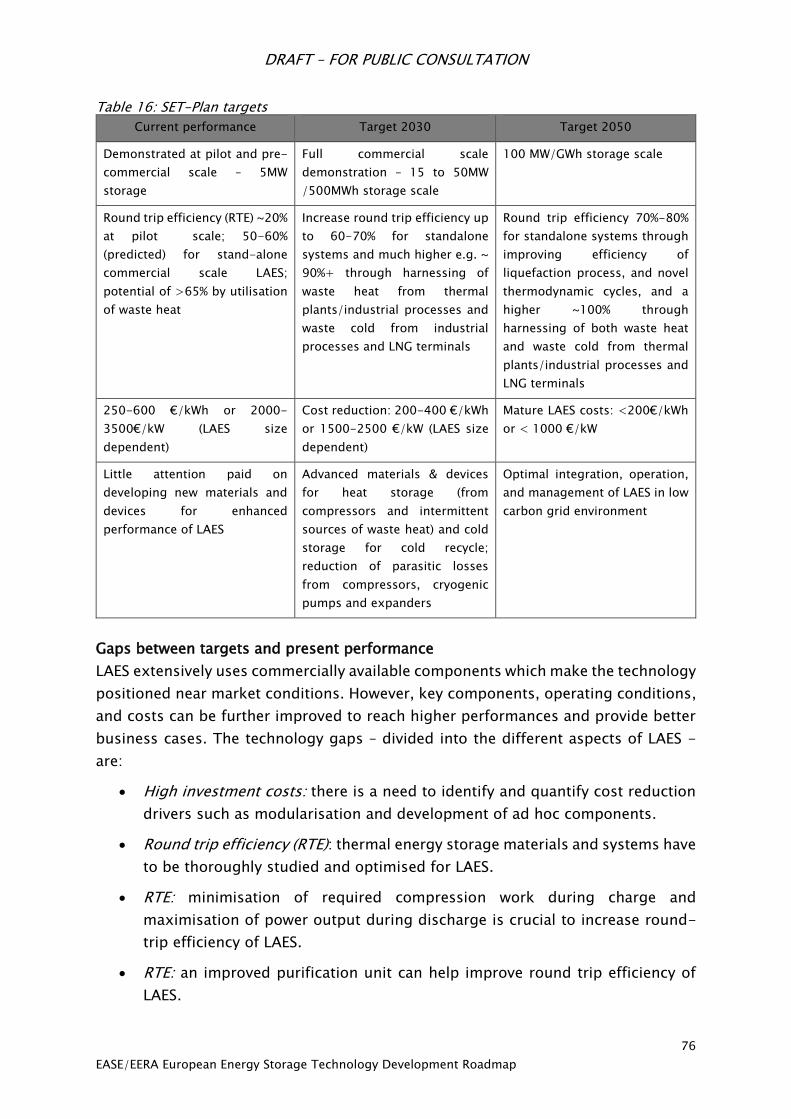
DRAFT – FOR PUBLIC CONSULTATION
76
EASE/EERA European Energy Storage Technology Development Roadmap
Table 16: SET-Plan targets
Current performance Target 2030 Target 2050
Demonstrated at pilot and pre-
commercial scale – 5MW
storage
Full commercial scale
demonstration – 15 to 50MW
/500MWh storage scale
100 MW/GWh storage scale
Round trip efficiency (RTE) ~20%
at pilot scale; 50-60%
(predicted) for stand-alone
commercial scale LAES;
potential of >65% by utilisation
of waste heat
Increase round trip efficiency up
to 60-70% for standalone
systems and much higher e.g. ~
90%+ through harnessing of
waste heat from thermal
plants/industrial processes and
waste cold from industrial
processes and LNG terminals
Round trip efficiency 70%-80%
for standalone systems through
improving efficiency of
liquefaction process, and novel
thermodynamic cycles, and a
higher ~100% through
harnessing of both waste heat
and waste cold from thermal
plants/industrial processes and
LNG terminals
250-600 €/kWh or 2000-
3500€/kW (LAES size
dependent)
Cost reduction: 200-400 €/kWh
or 1500-2500 €/kW (LAES size
dependent)
Mature LAES costs: <200€/kWh
or < 1000 €/kW
Little attention paid on
developing new materials and
devices for enhanced
performance of LAES
Advanced materials & devices
for heat storage (from
compressors and intermittent
sources of waste heat) and cold
storage for cold recycle;
reduction of parasitic losses
from compressors, cryogenic
pumps and expanders
Optimal integration, operation,
and management of LAES in low
carbon grid environment
Gaps between targets and present performance
LAES extensively uses commercially available components which make the technology
positioned near market conditions. However, key components, operating conditions,
and costs can be further improved to reach higher performances and provide better
business cases. The technology gaps – divided into the different aspects of LAES -
are:
High investment costs: there is a need to identify and quantify cost reduction
drivers such as modularisation and development of ad hoc components.
Round trip efficiency (RTE): thermal energy storage materials and systems have
to be thoroughly studied and optimised for LAES.
RTE: minimisation of required compression work during charge and
maximisation of power output during discharge is crucial to increase round-
trip efficiency of LAES.
RTE: an improved purification unit can help improve round trip efficiency of
LAES.

DRAFT – FOR PUBLIC CONSULTATION
77
EASE/EERA European Energy Storage Technology Development Roadmap
RTE: integration of LAES with conventional plants, as it has the potential to
increase overall efficiency. Comprehensive integration studies and full scale
demonstration should be implemented.
Missing optimal operation and dispatching of LAES plants: complete system
analyses and optimal integration with the grid are needed to achieve the best
technological benefit, maximise revenues, and improve business cases for
LAES.
Research Priorities
The following research priorities will be key to support the development of cost-
effective LAES technologies:
1. Intense thermal energy storage (TES) materials, devices and systems research
will be necessary to achieve substantial improvements in storing heat and cold
during charge and discharge processes of LAES. Research should be directed
at improving cycling operation of TES systems, increasing energy storage
density, and minimising costs.
2. Research should be conducted to maximise performance of cryogenic pumps
and compressors for LAES. Cryo-pumps that can achieve optimal pressure for
the LAES discharge process should be sought while solutions for removal and
storage of heat of compression should be developed for the compression
stages.
3. Exploratory research on advanced air purification units is recommended.
Removal of CO2, humidity, Argon, etc. by adsorption phenomena could
represent an extra source of heat/cold storage in LAES. However, novel cost
effective materials and design should be developed to exploit this opportunity.
4. Development of novel cycles for the discharge process. Currently liquid air is
directly expanded through turbomachinery to generate power output. Novel
indirect combined cycles have the potential of increasing LAES round trip
efficiency. In particular, Indirect Rankine cycles with cryogenic fluids such as
CO2, CH4 and C3H8 should be investigated and demonstrated at pilot scale.
5. Detailed integrated LAES-conventional plants design should be developed.
LAES has the potential to exploit streams of waste heat from conventional
power plants and industrial processes. Detailed studies and full-scale
demonstration for coal plants, open cycle gas turbines, and diesel generators
should be conducted to fully show LAES’s potential and provide business
cases.
6. Best operation and dispatching strategies for LAES plants should be
researched. Optimal integration of LAES into the grid will strongly depend on
installation locations, the market framework, and regulation. A lack of tailored
DRAFT – FOR PUBLIC CONSULTATION
78
EASE/EERA European Energy Storage Technology Development Roadmap
operational strategy could potentially lead to missed revenues and missed
technical benefits for the energy system. Thus, a range of operation strategies
should be developed for current and future market scenarios anticipating the
role of LAES in low carbon grids. Particular attention should be given to the
mutual interactions which may arise when LAES integrates with other
conventional power plants; as off-design conditions may arise, optimal
operations should be sought to achieve maximum benefit from the integrated
power generation system. The enhancement of LAES response time through
the integration of spin-gen technology could also be studied.
Recommendations for research funding, infrastructure and incentives
LAES requires support and industrial uptake for further technical development and to
enhance the market readiness level. Industrial-academic consortiums should be
supported to design, implement, and operate full-scale LAES demonstrators in
multiple technical/economic environments. Strong support for academic research in
new materials, components and devices, and novel system configurations will be
required to maximise LAES performance and reduce overall costs. Similarly, adequate
regulatory aspects and sound market conditions are necessary for the large-scale
industrial uptake of LAES.

DRAFT – FOR PUBLIC CONSULTATION
79
EASE/EERA European Energy Storage Technology Development Roadmap
Pumped Hydro Storage
Introduction
Pumped Hydro energy storage (PHS) is among the most efficient and flexible large-
scale means of storing energy
available today. This proven
technology allows not only to
produce electric energy, as
hydropower plants do, but also
to store it in the form of
gravitational potential energy
of the water. During periods
with high demand or energy
high prices, the water, stored in
an upper reservoir, is released
through turbines to a lower
reservoir in order to produce
electricity. During periods with
low demand or energy prices, the
water is pumped back from the
lower reservoir to the upper reservoir to store it.
PHS plants require very specific site conditions to be feasible and viable, including
proper ground conformation, difference in elevation between the reservoirs, and
water availability. The reservoirs are generally located above ground, but some
unconventional applications adopt the sea as lower reservoir (seawater pumped hydro
energy storage) or underground caverns as lower or, less often, upper reservoir
(underground pumped hydro energy storage).
In recent years, pump-turbines have been also operated with variable-speed motor-
generators (variable-speed pump-turbines), which enables operation over a wider
range of operating conditions by varying the pump-turbine rotation in speed (at the
time being ±10 % of the nominal speed). While in generating mode, the variable-
speed technology has allowed to reach an operating range comparable to ternary set,
while in pumping mode the ternary type still remains more flexible102. This also
increases both the flexibility and response time of PHS plants.
102 Electric Power Research Institute (EPRI), “Quantifying the Value of Hydropower in the Electric Grid:
Final Report”, Palo Alto, CA, 2013. 1023144.
Figure 13: Principle of a Pumped Hydro Storage plant

DRAFT – FOR PUBLIC CONSULTATION
80
EASE/EERA European Energy Storage Technology Development Roadmap
Maturity of technology
PHS is undoubtedly the most mature large-scale energy storage technology. Today,
in Europe, this technology represents 99 % of the on-grid electricity storage103. PHS
has long been the standard solution for peak shifting in Western Europe, where
inexpensive nuclear power is used to supply base load demand and to pump water
to the upper reservoir of PHS plants during periods of low demand. It is now becoming
increasingly common to manage the fluctuations variable RES supply in North Western
Europe using PHS104.
PHS plants are equipped with hydraulic, mechanical, electrical, and in some cases
power electronics equipment, most of which have already reached a TRL of 9 (actual
system proven in operational investment). The power of PHS plants ranges from
approximately 20 to 500 MW. The most typical values are between 200 and 350 MW,
with a storage capacity of 4 to 24 hours at full load for closed-loop PHS and
depending on the upper reservoir dimensions for open-loop PHS. PHS plants are
generally installed in mountainous or hilly areas where heads of 75-1500 metres can
be obtained. PHS holds excellent grid connection properties, as illustrated in table 17
and figure 14, below.
Table 17 – PHS features (VS = variable-speed, TS = Ternary Set)
General
Performances
50 to 500 MW
200 to 350 MW
Output/Input
Most Typical values
>> 8 hours full load Storage capacity
75 to 1500 m
~100 to ~600m
Head Range
Single stage reversible pump-turbine
> 80% Cycle efficiency
Reaction Time ~15 s 50% to 100% Generation
< 2 min 0% to 100% Generation
~ 1 min (TS) / ~4 min (VS) 0% to 100% Pumping
~ 1 min (TS) / ~8 min (VS) 100% Generation to 100% Pumping
Ancillary Services 15% (TS) / 25% (VS) to 100% Production adjustment range
~0% (TS) / 70% (VS) to 100% Pumping power adjustment range
Reactive power, Primary frequency response, Black start capability
103 Electric Power Research Institute (EPRI), “Electric Energy Storage Technology Options: A White Paper
Primer on Applications, Costs and Benefits”, Palo Alto, CA, 2010.
104 eSTORAGE: Potential for conversion of classical PSP to variable speed units in EU15, Norway and
Switzerland, April 2016. http://www.estorage-project.eu/wp-content/uploads/2013/06/EXTRACT-of-
eStorage-D4.1-Potential-for-conversion-of-classical-PSP-to-variable-speed-units.pdf
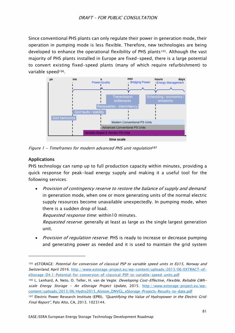
DRAFT – FOR PUBLIC CONSULTATION
81
EASE/EERA European Energy Storage Technology Development Roadmap
Since conventional PHS plants can only regulate their power in generation mode, their
operation in pumping mode is less flexible. Therefore, new technologies are being
developed to enhance the operational flexibility of PHS plants105. Although the vast
majority of PHS plants installed in Europe are fixed-speed, there is a large potential
to convert existing fixed-speed plants (many of which require refurbishment) to
variable speed106.
Figure 1 - Timeframes for modern advanced PHS unit regulation107
Applications
PHS technology can ramp up to full production capacity within minutes, providing a
quick response for peak-load energy supply and making it a useful tool for the
following services:
Provision of contingency reserve to restore the balance of supply and demand:
in generation mode, when one or more generating units of the normal electric
supply resources become unavailable unexpectedly. In pumping mode, when
there is a sudden drop of load.
Requested response time: within10 minutes.
Requested reserve: generally at least as large as the single largest generation
unit.
Provision of regulation reserve: PHS is ready to increase or decrease pumping
and generating power as needed and it is used to maintain the grid system
105 eSTORAGE: Potential for conversion of classical PSP to variable speed units in EU15, Norway and
Switzerland, April 2016. http://www.estorage-project.eu/wp-content/uploads/2013/06/EXTRACT-of-
eStorage-D4.1-Potential-for-conversion-of-classical-PSP-to-variable-speed-units.pdf
106 L. Lenhard, A. Neto, O. Teller, H. van de Vegte: Developing Cost-Effective, Flexible, Reliable GWh-
scale Energy Storage – An eStorage Project Update, 2015. http://www.estorage-project.eu/wp-
content/uploads/2013/06/Hydro2015_Alstom_DNVGL_eStorage-Projects-Results-to-date.pdf
107 Electric Power Research Institute (EPRI), “Quantifying the Value of Hydropower in the Electric Grid:
Final Report”, Palo Alto, CA, 2013. 1023144.

DRAFT – FOR PUBLIC CONSULTATION
82
EASE/EERA European Energy Storage Technology Development Roadmap
frequency at a narrow band around the nominal value by balancing supply and
demand. Frequency response is very similar to regulation but it requires a
shorter response time. Since frequency containment or primary control reserve
has to be capable of being activated within seconds, normally pumped storage
plants cannot be applied unless they are already in operation or they are
specifically designed for fast activation times.
Requested response time: seconds to a few minutes.
Load following: the PHS provides fast ramping capacity in order to respond to
a rapid or randomly fluctuating load profile.
Expected up- and down-ramp rate: MW/minute.
Timeframe: minutes.
Load shifting (energy arbitrage): the PHS increases the efficiency of system
operation by increasing the generation of base load units and decreasing the
operation of expensive peaking units.
Black start: the PHS provides an active reserve of power and energy within the
grid. It can be used to energise transmission and distribution lines and to
provide station power to bring power plants on line after a catastrophic failure
of the grid.
Voltage support: the PHS can generate reactive power to maintain grid voltage
within specific limits so as to operate the transmission system in a stable
manner.
SET-Plan targets
Table 18 - SET Plan targets for hydro energy storage technologies towards 2030 and beyond
Current performance Target 2020-2030 Target 2050
GW storage
Low cycle cost high capital
cost
$500/kW to $2000/kW (350
to 1500€/kW)
Round trip efficiency 70-80%
Primary regulation capacity
Materials radical
redesign & research on
power electronic
components
Turbine efficiency
improvement
Increase regulation
capacity in pumping
mode
Efficiency improvement
Cost reduction
Expand possibilities of PHS
installations
Ultrafast regulation

DRAFT – FOR PUBLIC CONSULTATION
83
EASE/EERA European Energy Storage Technology Development Roadmap
Increase pump-turbine
stability in pumping
mode
New concepts for
underground PHS
Studies for first Implementation of
new underground PHS
Gaps between targets and present performance
The way to operate PHS has changed dramatically following the integration of a large
amount of variable generation with an increasing need to provide frequency
regulation and therefore for PHS to be operated over a wider range of power and with
the shortest possible reaction time. The need for increased flexibility is therefore one
key area for development.
Pump turbines must be optimised to provide a wide range of power in generation
mode. Variable speed technology needs to be further developed (from ±10% to
±100%) in order to increase the regulation capacity in pumping mode. This will also
necessitate developing a new concept of pump turbines able to provide the full
benefit of regulation in pumping mode.
In the long term, the introduction of large high voltage DC (HVDC) electric highways
combined with the development of a large quantity of generation assets connected
through power electronics will create new needs for ultra-fast regulation, requiring
PHS units to operate as flywheels, delivering power regulation within milliseconds.
The other major gap between needs and present performance is to reduce the
inherent limitation that is PHS’s dependence on geography. Equipping very high head
(above ~700m) and very low head (below ~100m) sites remains challenging due to
different problems: current multi-stage reversible pump-turbines (RPTs) used above
1000m head do not provide power regulation in generating mode; in low-head sites,
the pump-turbine behaviour at part load is affected by too low efficiency in both
modes and by unstable operating conditions in pumping mode.
Therefore, very high head pumped storage power plants would require new,
economically viable solutions to provide the much needed flexibility: technologies
such as variable speed or multiple stages regulated RPT need further developments.
This should foster developments for equipment for higher and lower head sites and
for upgrading conventional hydro into PHP as well as for new energy storage plant
concepts.
Research priorities
Some of the main research priorities for PHS are the following:
1. Increasing PHS flexibility by:
Developing a full range variable-speed motor generator (±100%) to allow
secondary regulation in pumping mode (suggested target for 2030) and, in
DRAFT – FOR PUBLIC CONSULTATION
84
EASE/EERA European Energy Storage Technology Development Roadmap
the long term, to allow the PHS units to operate as flywheels and deliver
power regulation in milliseconds (suggested target for 2050). Possible
synergies between PHS technology and HVDC technology to develop large
variable speed solutions with power electronics on the stator should be
investigated;
Increasing the pump-turbine stability during transition between operating
modes and at part loads in pumping mode in order to shorten start-up and
transition times (from seconds to few minutes) and to favour the
exploitation of low-head site. The development of new design criteria for
pump-turbines will be necessary (suggested 2030 target).
2. Expanding possibilities for installation of PHS by:
Developing pump-turbines allowing the upgrading of conventional hydro
power plants into PHS while keeping the existing powerhouses to minimise
costs and environmental impacts. This will require a new pump-turbine
design particularly focusing on the cavitation behaviour to overcome the
problems related with the general need of lower foundations in pumping
mode (2030 target);
Studying the development of PHS adopting the sea as a lower reservoir or
underground cavern as a lower or, less often, upper reservoir (2050 target);
For various types of new underground PHS, the development of a standard
geology based site selection scheme, including identification and
evaluation processes for the different public and industrial stakeholders, is
essential. It has to be coupled with a new specialised multi-modal safety
operation monitoring concept (2030 target);
Expanding possibilities to equip more complex sites: going to very high
head with the development of multiple stage solutions and very low head
with other types of turbines (Deriaz or bulb). Particular application of a low
head PHS to investigate will be the Energy Island concept with a reservoir
in the sea (2050 target).
3. In a long-term perspective it will be extremely useful to support research on
new PHS concepts (e.g. by moving solid mass like soil, gravity power, and
bladder reservoir).
4. In order to increase turbine and pump-turbine lifetime, a better understanding
of the fluid-structure interactions to limit vibrations coming from hydraulic
“turbulences” will be required.
5. Developing standardised mini/micro cost-competitive PHP applications as well
as hybrid PHS-wind/photovoltaic applications for centralised/decentralised
solutions should be supported.
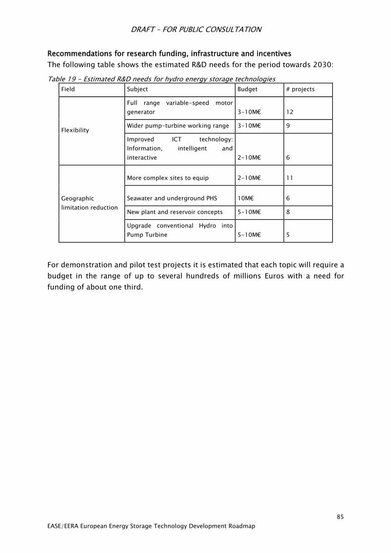
DRAFT – FOR PUBLIC CONSULTATION
85
EASE/EERA European Energy Storage Technology Development Roadmap
Recommendations for research funding, infrastructure and incentives
The following table shows the estimated R&D needs for the period towards 2030:
Table 19 - Estimated R&D needs for hydro energy storage technologies
Field Subject Budget # projects
Flexibility
Full range variable-speed motor
generator 3-10M€ 12
Wider pump-turbine working range 3-10M€ 9
Improved ICT technology:
Information, intelligent and
interactive 2-10M€ 6
Geographic
limitation reduction
More complex sites to equip 2-10M€ 11
Seawater and underground PHS 10M€ 6
New plant and reservoir concepts 5-10M€ 8
Upgrade conventional Hydro into
Pump Turbine 5-10M€ 5
For demonstration and pilot test projects it is estimated that each topic will require a
budget in the range of up to several hundreds of millions Euros with a need for
funding of about one third.
DRAFT – FOR PUBLIC CONSULTATION
86
EASE/EERA European Energy Storage Technology Development Roadmap
6.5 Thermal Energy Storage
Thermal energy storage (TES) can be divided into three distinct storage principles:
sensible heat storage, latent heat storage, and thermochemical heat storage. These
three principles differ in the fundamental way they store thermal energy.
Sensible heat storages (SHS) raise and lower the temperature of a liquid or
solid storage medium (e.g. water, sand, molten salts, rocks, with water being
the cheapest option) in order to store and release thermal energy for low-
temperature applications. This is the most common form of thermal energy
storage and has found commercial success on residential and industrial scales.
Latent heat storage (LHS) takes advantage of the energy absorbed or released
at constant temperature during a phase change of the material. In most cases,
solid/liquid phase change is utilised, with melting used to store heat and
solidification used to release heat.
Thermochemical heat storage (TCS) operates in two ways: chemical reactions
and sorption processes. In the former, energy is stored as the heat of reaction
of reversible reactions. The latter stores thermal energy either through
adsorption (physical bonding) or absorption (uptake/dissolution of a material).
In general, thermal energy storage is a cross-cutting technology that will contribute
manifold to a future energy system by:
increasing the share of renewable, low carbon energies, especially for solar
thermal technologies and with power-to-heat concepts;
adding operational flexibility to (fossil fuel) power plants and industrial
processes,
enabling waste heat recovery in industrial processes, and
increasing energy efficiency in industrial processes and in buildings.
Table 20, below, portrays the complex picture of possibilities for integration of
thermal energy storages in different applications. It is important to note that there is
no simple 1-to-1 match for technology and application and so far only selected
examples of commercially available thermal energy storage technologies are to be
found. The definition and values of key performance indicators for TES are highly
dependent on the specific application and process benefit could vary from case to
case. The following chapters cover each storage principle independently.

DRAFT – FOR PUBLIC CONSULTATION
87
EASE/EERA European Energy Storage Technology Development Roadmap
Table 20: Applicability of thermal storage technologies for different applications
Sensible Latent TCS
Use and Integration
of Low Carbon
Energy for
Heat Generation
Demand-driven/stabilising heat supply from local and district heating
+ 0 0
Demand-driven/stabilising heat supply
from solar process heat + + +
Demand-driven/stabilising heat deployment from solar thermal power plants
+ + 0
Decarbonisation of the residential heating sector using intermittent renewable energy (e.g wind, solar PV)
+ + 0
Utilisation of Power-to-Heat concepts + + 0
Combined solar systems + 0 0
Increasing Energy
Efficiency in
Industrial Processes
Use of industrial waste heat + + +
Decoupling of power, heat and cold generation in cogeneration plants
+ + 0
Increasing Energy
Efficiency in
Buildings
Balancing heat and cold demand + + +
Decoupling of power, heat and cold
generation in micro-cogen plants + + 0
Balancing daily demand + + +
Balancing seasonal demand + 0 +
* PLUS (+) Typical/favourable application
** NEUTRAL (0) Possible application
Sensible Heat Storage
Introduction
Sensible heat storages are the most commonly deployed type of TES. From small
residential water tanks to massive molten salt storages in concentrating solar power
(CSP) plants or Cowper storages for blast furnaces, all systems operate by the same
fundamental principle: increasing or decreasing the
temperature of a solid or liquid substance with high
heat capacity to store or release thermal energy,
transferring the heat directly or indirectly to the
process.
Water is a very cost-effective, non-toxic storage
medium used at temperatures below 120°C. In
combination with solar thermal heating, small, well-
insulated storages are commonly built as
Figure 15: Crescent Dunes molten salt storage tank
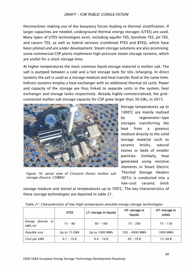
DRAFT – FOR PUBLIC CONSULTATION
88
EASE/EERA European Energy Storage Technology Development Roadmap
thermoclines making use of the buoyancy forces leading to thermal stratification. If
larger capacities are needed, underground thermal energy storages (UTES) are used.
Many types of UTES technologies exist, including aquifer TES, borehole TES, pit TES,
and cavern TES, as well as hybrid versions (combined PTES and BTES), which have
been piloted and are under development. Steam storage solutions are also promising:
some commercial CSP plants implement high pressure steam storage systems, which
are useful for a short storage time.
At higher temperatures the most common liquid storage material is molten salt. The
salt is pumped between a cold and a hot storage tank for (dis-)charging. In direct
systems the salt is used as a storage medium and heat transfer fluid at the same time.
Indirect systems employ a heat exchanger with an additional thermal oil cycle. Power
and capacity of the storage are thus linked to separate units in the system, heat
exchanger and storage tanks respectively. Already highly commercialised, the grid-
connected molten salt storage capacity for CSP grew larger than 30 GWth in 2015.
Storage temperatures up to
1000°C are mainly realised
by regenerator-type
storages transferring the
heat from a gaseous
medium directly to the solid
storage material such as
ceramic bricks, natural
stones or beds of smaller
particles. Similarly, heat
generated using resistive
elements in Smart Electric
Thermal Storage Heaters
(SETs) is conducted into a
low-cost ceramic brick
storage medium and stored at temperatures up to 700°C. The key characteristics of
these storage technologies are depicted in table 21.
Table 21: Characteristics of low/high temperature sensible energy storage technologies
UTES LT-storage in liquids HT-storage in
liquids
HT-storage in
solids
Energy density in
kWh/m3 15 - 80 60 - 100 75 – 200 75 – 150
Feasible size Up to 15 GWh Up to 1000 MWh 350 – 4000 MWh 1000 MWh
Cost per kWh 0.1 – 10 € 0.4 – 10 € 20 – 70 € 15-40 €
Figure 16: aerial view of Crescent Dunes molten salt storage (Source: COBRA)

DRAFT – FOR PUBLIC CONSULTATION
89
EASE/EERA European Energy Storage Technology Development Roadmap
Maturity of Technology
Many sensible heat storage technologies have been in development for decades. This
is especially true for low temperature water storages whereby small-scale, single-
home storages for solar thermal heat are commercially available products (TRL 9).
Larger storages for district heating are on a demonstration level or industrially used
for heating plants (TRL 8-9). Underground thermal energy storages are commonly
used in Denmark, Sweden, The Netherlands, and Norway for seasonal storage of heat
in centralised and distributed energy systems. In these countries UTES is applied
together with renewable solar or geothermal heat and electricity from photovoltaics
in combination with district heating (TRL 9), whereas in other European countries they
are still on a demonstration and pilot level.
Far fewer examples are available of thermal energy storages at higher temperature
levels. Molten salt storages have become the standard solution for dispatchable solar
thermal electricity generation and have reached high TRL levels for this application
(TRL 9). However, in other industrial applications they are not yet commercially
available (TRL 4-6). The same is true for regenerator-type storages which are
commercially deployed in steel and glass industries for waste heat recovery. Usage in
power plant engineering is underway but pre-commercial (TRL 6-7).
In contrast, thermal energy has been stored within ceramic bricks at temperatures up
to 70°C in residential storage heaters since the mid-20th century. Modern versions
of these appliances, SETs, are commercially available and are being used to store vast
amounts of thermal energy across tens of thousands of residential properties. With
their advanced ICT and communication networks, these SETs are also delivering
services, such as demand side management and frequency response, to the electricity
industry, enabling it to increase the penetration of low carbon energy sources (e.g.
Wind and PV) at both a local and national level. The advanced ICT in SETs is also
enabling them to learn their environment and adapt their levels of stored thermal
energy for maximum efficiency.
Applications
Sensible heat storage applications include:
District heating: TES systems providing balancing demand and supply services on
an hourly, daily or seasonal basis. Technologies applied are UTES, tank, and pit
storages.
Single-home storage systems: low-temperature solar heat of up to 40 m3 for high
solar shares.
Concentrating solar power: molten salt technologies have been extensively
deployed in CSP applications for storage of thermal energy prior to steam or
electricity generation. This usage allows CSP plants to generate highly
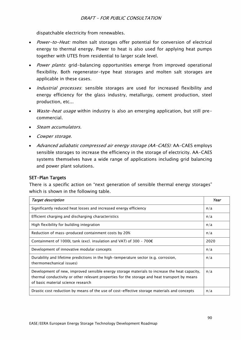
DRAFT – FOR PUBLIC CONSULTATION
90
EASE/EERA European Energy Storage Technology Development Roadmap
dispatchable electricity from renewables.
Power-to-Heat: molten salt storages offer potential for conversion of electrical
energy to thermal energy. Power to heat is also used for applying heat pumps
together with UTES from residential to larger scale level.
Power plants: grid-balancing opportunities emerge from improved operational
flexibility. Both regenerator-type heat storages and molten salt storages are
applicable in these cases.
Industrial processes: sensible storages are used for increased flexibility and
energy efficiency for the glass industry, metallurgy, cement production, steel
production, etc...
Waste-heat usage within industry is also an emerging application, but still pre-
commercial.
Steam accumulators.
Cowper storage.
Advanced adiabatic compressed air energy storage (AA-CAES): AA-CAES employs
sensible storages to increase the efficiency in the storage of electricity. AA-CAES
systems themselves have a wide range of applications including grid balancing
and power plant solutions.
SET-Plan Targets
There is a specific action on “next generation of sensible thermal energy storages”
which is shown in the following table.
Target description Year
Significantly reduced heat losses and increased energy efficiency n/a
Efficient charging and discharging characteristics n/a
High flexibility for building integration n/a
Reduction of mass-produced containment costs by 20% n/a
Containment of 1000L tank (excl. insulation and VAT) of 300 – 700€ 2020
Development of innovative modular concepts n/a
Durability and lifetime predictions in the high-temperature sector (e.g. corrosion,
thermomechanical issues)
n/a
Development of new, improved sensible energy storage materials to increase the heat capacity,
thermal conductivity or other relevant properties for the storage and heat transport by means
of basic material science research
n/a
Drastic cost reduction by means of the use of cost-effective storage materials and concepts n/a
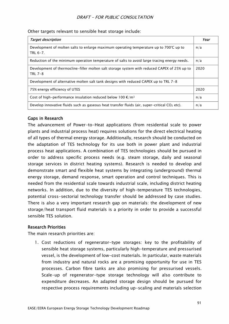
DRAFT – FOR PUBLIC CONSULTATION
91
EASE/EERA European Energy Storage Technology Development Roadmap
Other targets relevant to sensible heat storage include:
Target description Year
Development of molten salts to enlarge maximum operating temperature up to 700°C up to
TRL 6-7.
n/a
Reduction of the minimum operation temperature of salts to avoid large tracing energy needs. n/a
Development of thermocline-filler molten salt storage system with reduced CAPEX of 25% up to
TRL 7-8
2020
Development of alternative molten salt tank designs with reduced CAPEX up to TRL 7-8
75% energy efficiency of UTES 2020
Cost of high-performance insulation reduced below 100 €/m3 n/a
Develop innovative fluids such as gaseous heat transfer fluids (air, super-critical CO2 etc). n/a
Gaps in Research
The advancement of Power-to-Heat applications (from residential scale to power
plants and industrial process heat) requires solutions for the direct electrical heating
of all types of thermal energy storage. Additionally, research should be conducted on
the adaptation of TES technology for its use both in power plant and industrial
process heat applications. A combination of TES technologies should be pursued in
order to address specific process needs (e.g. steam storage, daily and seasonal
storage services in district heating systems). Research is needed to develop and
demonstrate smart and flexible heat systems by integrating (underground) thermal
energy storage, demand response, smart operation and control techniques. This is
needed from the residential scale towards industrial scale, including district heating
networks. In addition, due to the diversity of high-temperature TES technologies,
potential cross-sectorial technology transfer should be addressed by case studies.
There is also a very important research gap on materials: the development of new
storage/heat transport fluid materials is a priority in order to provide a successful
sensible TES solution.
Research Priorities
The main research priorities are:
1. Cost reductions of regenerator-type storages: key to the profitability of
sensible heat storage systems, particularly high-temperature and pressurised
vessel, is the development of low-cost materials. In particular, waste materials
from industry and natural rocks are a promising opportunity for use in TES
processes. Carbon fibre tanks are also promising for pressurised vessels.
Scale-up of regenerator-type storage technology will also contribute to
expenditure decreases. An adapted storage design should be pursued for
respective process requirements including up-scaling and materials selection
DRAFT – FOR PUBLIC CONSULTATION
92
EASE/EERA European Energy Storage Technology Development Roadmap
for cost reduction.
2. Increases in reliability, system lifetime, and process integration of high-
temperature storages: projects on high-temperature process integration of
steel, building material, and glass industries as well as power plant processes
(improvement of flexibility for grid support).
3. Research in the area of power-to-heat technology with high-grade heat
utilisation.
4. Research on novel high-temperature TES concepts for cost reduction or
improved operation in system (e.g. thermocline/filler of molten salt storage,
solid particle concepts).
5. Materials development for molten salts but also other materials for sensible
TES. Molten salt material development should focus on the expansion of the
temperature range through the development of new mixtures of molten salts.
Active research is being done on new sensible TES material alternatives,
investigating both the storage media and the transfer fluid. This includes new,
low-cost materials alternatives such as materials coming from industrial waste
and, on the fluid side, ionic liquids and gaseous fluids (air, pressurised CO2
etc).
6. For UTES, there is a need to assess the potential and suitability of the
subsurface in Europe. Further there is a need for research and demonstration
regarding high temperature storage systems (>100°C) and hybrid UTES
systems to increase capacity, efficiency and alignment with renewable heat
production technologies (solar heat, geothermal heat, biomass heat).
7. Molten salt fundamental research: clarification of metallic corrosion and
nitrate salt chemistry aspects in the upper temperature ranges. Joint research
efforts are recommended in the fields of applied research and materials
institutes focusing on mineralogy (e.g. natural stones), molten salts, metallic
corrosion, and high temperature free-flowing particles.
Recommendations for Research, Funding, Infrastructure and Incentives
There is a diversity of high-temperature TES options with different maturity levels.
For high-temperature TES, funding should be directed towards a direct high-
temperature TES funding frame. This would enable to full technology transfer
potential of high-temperature TES as a cross-sectional technology.
With respect to cost reductions for regenerator-type storages, funding should be
made available to make an effective valorisation process of low-cost materials (e.g.
steel slag). This view is aligned with a commitment to a “Circular Economy” with a
cross-sectorial added-value approach. This approach has also been suggested in the
DRAFT – FOR PUBLIC CONSULTATION
93
EASE/EERA European Energy Storage Technology Development Roadmap
European Parliament’s Briefing on the EU Heating and Cooling Strategy108.
Additionally, costs can be reduced through thermocline approaches for molten salt
storage systems in combination with solid filler materials.
For the concentrating solar power (CSP) application, it will be important to convince
decision makers to demonstrate novel TES technologies at a relevant scale. Hence,
funding of pre-commercial plants including novel high-temperature TES systems is
recommended. Small- to medium-scale European demonstrations and pilot
programs should be established with a focus on increased flexibility of industrial
processes through heat storage integration. Such activities will be necessary to make
the processes compatible with Power-to-Heat techniques fed from fluctuating
electricity in the mid- to long-term.
It is recommended to further demonstrate smart and flexible heat infrastructures by
integrating seasonal thermal energy storage, energy carrier coupling (Power-to-
Heat), demand response, and smart operation and control into existing district
heating networks in Europe. Funding estimate: €4-8 million per project.
108 European Parliament, Resolution of 13 September 2016 on an EU Strategy on Heating and Cooling
http://www.europarl.europa.eu/sides/getDoc.do?pubRef=-//EP//TEXT+TA+P8-TA-2016-
0334+0+DOC+XML+V0//EN
DRAFT – FOR PUBLIC CONSULTATION
94
EASE/EERA European Energy Storage Technology Development Roadmap
Latent Heat Storage
Introduction
Latent heat storage (LHS) can be divided into direct and indirect systems, both of
which provide critical solutions to the storage of latent heat. Direct systems facilitate
heat transfer through immediate contact between the heat transfer fluid (HTF) and
the LHS material. Indirect systems separate the HTF and storage material with a solid
heat transfer border, in which case heat can either be delivered to a container filled
with phase-change material (PCM) or an encapsulated material. In the first case, heat
transfer occurs by way of pipes, finned tubes or flat-plate exchangers. Concerning
encapsulated PCM, the material is separated in small packages which are then put in
contact with the heat transfer fluid. The form of the encapsulation depends on the
application and can be found in both stationary and mobile applications.
LHS provides the possibility to store a large amount of heat at a constant temperature,
the so called phase-change temperature, making it ideally suited for applications that
do not provide or allow for big temperature differences. Accordingly, each system
requires a PCM whose phase-change temperature lies in the range of the application.
PCMs are available in a broad temperature range. For low temperature storages, water
(ice storages) and aqueous salt solutions (for temperatures below 0°C) have been
commercialised and deployed on a large scale. Below 100°C, systems have also been
created based on salt hydrates and paraffin waxes. Research is also being performed
on systems for fatty acids (15 – 70°C), sugar alcohols (90 – 200°C), metal (metal
alloys), and salt (mixtures) for temperatures above 200°C.
A key application for high-temperature storages is systems which use steam as a
working fluid as well as condensation and evaporation for absorbing and releasing
heat. Depending on the working pressure, storage materials with a melting
temperature between 150°C and 330°C are required. Due to cost considerations,
nitrate salts and eutectic salt mixtures (i.e. mixtures of two or more salts that have a
lower melting temperature when combined than when separated) are normally the
main candidates109. However, metals have also revealed an attractive potential in this
temperature range and higher.
The key characteristics of these various storage technologies are depicted in table
22.
109 However, the cost of the material is not the only aspect determining the overall cost. A significant
thermal improvement due to enhanced thermal properties of another material could reduce other related
costs, making another technology attractive.
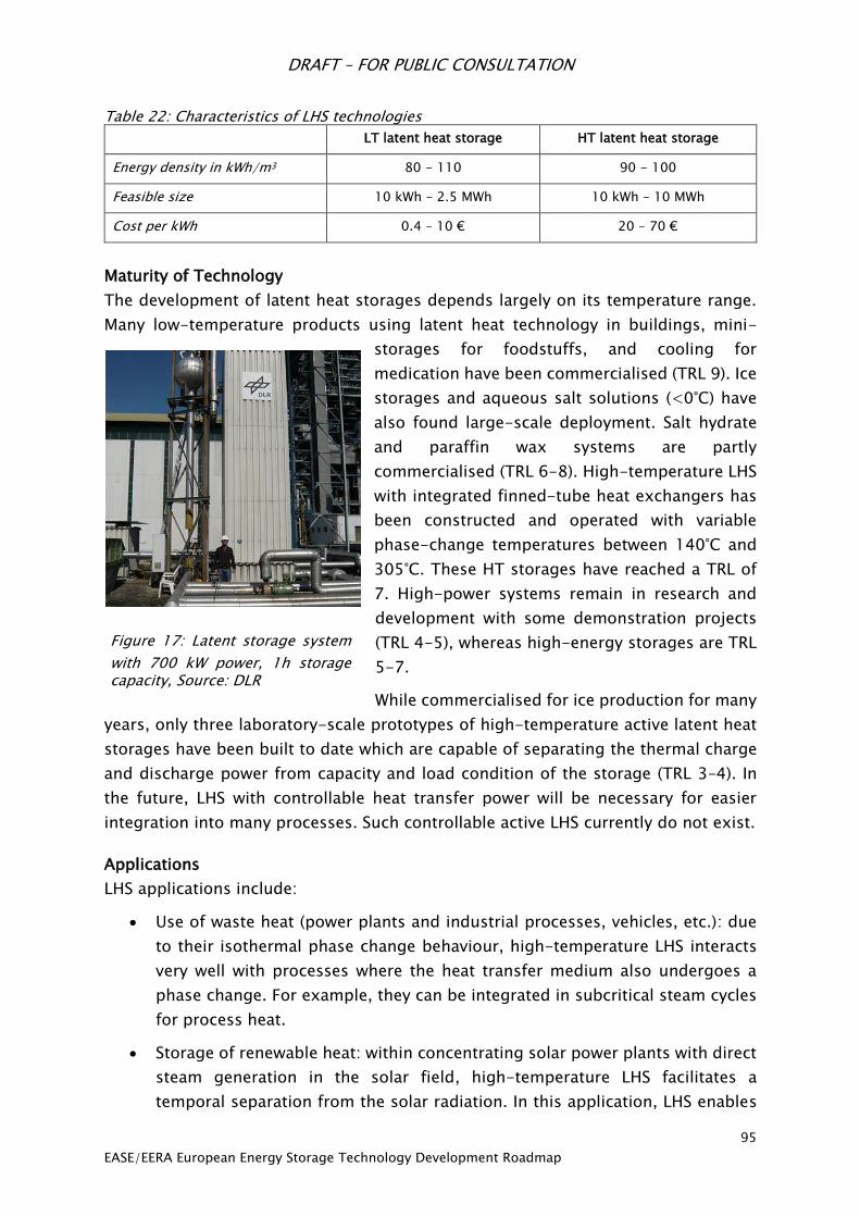
DRAFT – FOR PUBLIC CONSULTATION
95
EASE/EERA European Energy Storage Technology Development Roadmap
Table 22: Characteristics of LHS technologies
LT latent heat storage HT latent heat storage
Energy density in kWh/m3 80 - 110 90 - 100
Feasible size 10 kWh – 2.5 MWh 10 kWh – 10 MWh
Cost per kWh 0.4 – 10 € 20 – 70 €
Maturity of Technology
The development of latent heat storages depends largely on its temperature range.
Many low-temperature products using latent heat technology in buildings, mini-
storages for foodstuffs, and cooling for
medication have been commercialised (TRL 9). Ice
storages and aqueous salt solutions (<0°C) have
also found large-scale deployment. Salt hydrate
and paraffin wax systems are partly
commercialised (TRL 6-8). High-temperature LHS
with integrated finned-tube heat exchangers has
been constructed and operated with variable
phase-change temperatures between 140°C and
305°C. These HT storages have reached a TRL of
7. High-power systems remain in research and
development with some demonstration projects
(TRL 4-5), whereas high-energy storages are TRL
5-7.
While commercialised for ice production for many
years, only three laboratory-scale prototypes of high-temperature active latent heat
storages have been built to date which are capable of separating the thermal charge
and discharge power from capacity and load condition of the storage (TRL 3–4). In
the future, LHS with controllable heat transfer power will be necessary for easier
integration into many processes. Such controllable active LHS currently do not exist.
Applications
LHS applications include:
Use of waste heat (power plants and industrial processes, vehicles, etc.): due
to their isothermal phase change behaviour, high-temperature LHS interacts
very well with processes where the heat transfer medium also undergoes a
phase change. For example, they can be integrated in subcritical steam cycles
for process heat.
Storage of renewable heat: within concentrating solar power plants with direct
steam generation in the solar field, high-temperature LHS facilitates a
temporal separation from the solar radiation. In this application, LHS enables
Figure 17: Latent storage system
with 700 kW power, 1h storage capacity, Source: DLR
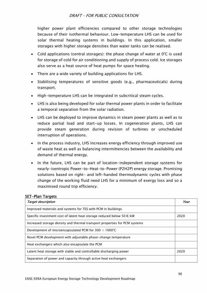
DRAFT – FOR PUBLIC CONSULTATION
96
EASE/EERA European Energy Storage Technology Development Roadmap
higher power plant efficiencies compared to other storage technologies
because of their isothermal behaviour. Low-temperature LHS can be used for
solar thermal heating systems in buildings. In this application, smaller
storages with higher storage densities than water tanks can be realised.
Cold applications (central storages): the phase change of water at 0°C is used
for storage of cold for air conditioning and supply of process cold. Ice storages
also serve as a heat source of heat pumps for space heating.
There are a wide variety of building applications for LHS.
Stabilising temperatures of sensitive goods (e.g., pharmaceuticals) during
transport.
High-temperature LHS can be integrated in subcritical steam cycles.
LHS is also being developed for solar thermal power plants in order to facilitate
a temporal separation from the solar radiation.
LHS can be deployed to improve dynamics in steam power plants as well as to
reduce partial load and start-up losses. In cogeneration plants, LHS can
provide steam generation during revision of turbines or unscheduled
interruption of operations.
In the process industry, LHS increases energy efficiency through improved use
of waste heat as well as balancing intermittencies between the availability and
demand of thermal energy.
In the future, LHS can be part of location-independent storage systems for
nearly-isentropic Power-to-Heat-to-Power (P2H2P) energy storage. Promising
solutions based on right- and left-handed thermodynamic cycles with phase
change of the working fluid need LHS for a minimum of exergy loss and so a
maximised round trip efficiency.
SET-Plan Targets
Target description Year
Improved materials and systems for TES with PCM in buildings
Specific investment cost of latent heat storage reduced below 50 €/kW 2020
Increased storage density and thermal transport properties for PCM systems
Development of microencapsulated PCM for 300 < 1000°C
Novel PCM development with adjustable phase-change temperature
Heat exchangers which also encapsulate the PCM
Latent heat storage with stable and controllable discharging power 2020
Separation of power and capacity through active heat exchangers
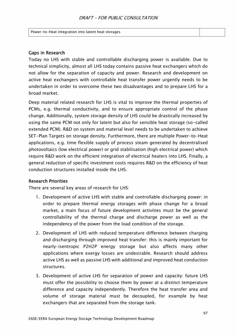
DRAFT – FOR PUBLIC CONSULTATION
97
EASE/EERA European Energy Storage Technology Development Roadmap
Power-to-Heat integration into latent heat storages
Gaps in Research
Today no LHS with stable and controllable discharging power is available. Due to
technical simplicity, almost all LHS today contains passive heat exchangers which do
not allow for the separation of capacity and power. Research and development on
active heat exchangers with controllable heat transfer power urgently needs to be
undertaken in order to overcome these two disadvantages and to prepare LHS for a
broad market.
Deep material related research for LHS is vital to improve the thermal properties of
PCMs, e.g. thermal conductivity, and to ensure appropriate control of the phase
change. Additionally, system storage density of LHS could be drastically increased by
using the same PCM not only for latent but also for sensible heat storage (so-called
extended PCM). R&D on system and material level needs to be undertaken to achieve
SET-Plan Targets on storage density. Furthermore, there are multiple Power-to-Heat
applications, e.g. time flexible supply of process steam generated by decentralised
photovoltaics (low electrical power) or grid stabilisation (high electrical power) which
require R&D work on the efficient integration of electrical heaters into LHS. Finally, a
general reduction of specific investment costs requires R&D on the efficiency of heat
conduction structures installed inside the LHS.
Research Priorities
There are several key areas of research for LHS:
1. Development of active LHS with stable and controllable discharging power: in
order to prepare thermal energy storages with phase change for a broad
market, a main focus of future development activities must be the general
controllability of the thermal charge and discharge power as well as the
independency of the power from the load condition of the storage.
2. Development of LHS with reduced temperature difference between charging
and discharging through improved heat transfer: this is mainly important for
nearly-isentropic P2H2P energy storage but also affects many other
applications where exergy losses are undesirable. Research should address
active LHS as well as passive LHS with additional and improved heat conduction
structures.
3. Development of active LHS for separation of power and capacity: future LHS
must offer the possibility to choose them by power at a distinct temperature
difference and capacity independently. Therefore the heat transfer area and
volume of storage material must be decoupled, for example by heat
exchangers that are separated from the storage tank.
DRAFT – FOR PUBLIC CONSULTATION
98
EASE/EERA European Energy Storage Technology Development Roadmap
4. Development of systems using the same PCM for latent and sensible heat
storage (extended PCM) in order to increase storage density. Material
development of PCM with distinct melting temperatures, melting enthalpy,
specific heat capacity and relationship between melting enthalpy and specific
heat capacity adjusted to various heat transfer fluids and specific processes is
needed.
5. Encapsulation of PCM as well as embedding in porous structures:
encapsulation of PCM offers the opportunity to use materials with
advantageous thermophysical behaviour but problematic properties like
toxicity and corrosivity. Encapsulated PCM can be directly brought in contact
with the heat transfer medium and so improve heat transfer.
6. Cost reduction: existing LHS technologies need to be reduced in material
expenditure in order to transfer technological advantages into cost-related
advantages. This includes mainly the heat transfer structure and the
containment but also the PCM itself.
Recommendations for Research Funding, Infrastructure and Incentives
The development of LHS with stable and controllable discharging power as well as
the separation of power and capacity first need fundamental research in order to
understand and quantify the heat transfer processes of active heat exchangers. As
this functionality is the key to prepare LHS for a broad market and the research on it
is the foundation for further developments, fundamental research projects should be
funded in a first step (approximately 3 projects at €1.5 million), particularly with a
focus on materials research to improve storage capacity, transport properties,
customisation of phase change temperature, latent heat, etc. A next step could be
the development of active heat exchangers in research/industry cooperation projects.
Demonstration of systems using the same PCM for latent and sensible heat storage
(extended PCM) and the resulting benefits (e.g. increase in storage density) should
be undertaken by co-funded integration of pilot storages into real applications.
However, such demonstration projects should be accompanied by fully funded
fundamental research on material development to adjust the phase change
temperatures and the specific heat capacity to specific applications. The development
of improved heat conduction structures and encapsulated PCM should be undertaken
in projects co-funded by industry and the public sector.
Thermochemical Heat Storage
Introduction
Thermochemical systems (TCS) stockpile heat in two distinct ways: chemical reactions
and sorption processes. Thermochemical reactions based on gas-gas or gas-solid
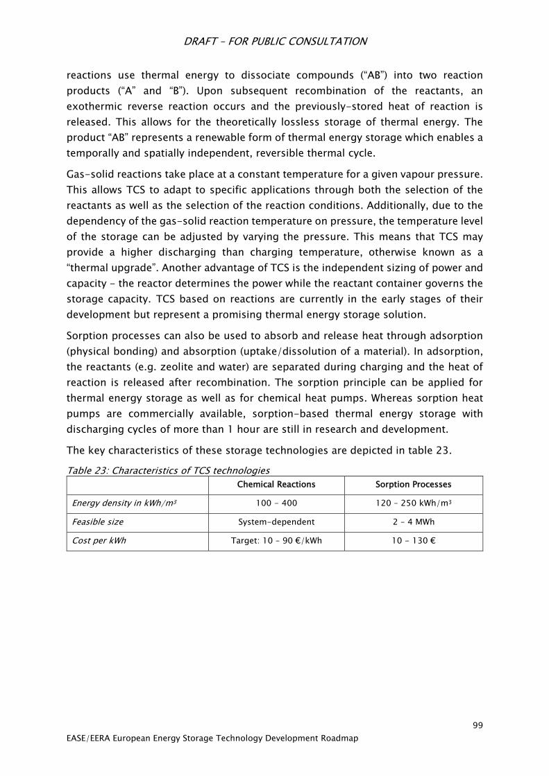
DRAFT – FOR PUBLIC CONSULTATION
99
EASE/EERA European Energy Storage Technology Development Roadmap
reactions use thermal energy to dissociate compounds (“AB”) into two reaction
products (“A” and “B”). Upon subsequent recombination of the reactants, an
exothermic reverse reaction occurs and the previously-stored heat of reaction is
released. This allows for the theoretically lossless storage of thermal energy. The
product “AB” represents a renewable form of thermal energy storage which enables a
temporally and spatially independent, reversible thermal cycle.
Gas-solid reactions take place at a constant temperature for a given vapour pressure.
This allows TCS to adapt to specific applications through both the selection of the
reactants as well as the selection of the reaction conditions. Additionally, due to the
dependency of the gas-solid reaction temperature on pressure, the temperature level
of the storage can be adjusted by varying the pressure. This means that TCS may
provide a higher discharging than charging temperature, otherwise known as a
“thermal upgrade”. Another advantage of TCS is the independent sizing of power and
capacity - the reactor determines the power while the reactant container governs the
storage capacity. TCS based on reactions are currently in the early stages of their
development but represent a promising thermal energy storage solution.
Sorption processes can also be used to absorb and release heat through adsorption
(physical bonding) and absorption (uptake/dissolution of a material). In adsorption,
the reactants (e.g. zeolite and water) are separated during charging and the heat of
reaction is released after recombination. The sorption principle can be applied for
thermal energy storage as well as for chemical heat pumps. Whereas sorption heat
pumps are commercially available, sorption-based thermal energy storage with
discharging cycles of more than 1 hour are still in research and development.
The key characteristics of these storage technologies are depicted in table 23.
Table 23: Characteristics of TCS technologies
Chemical Reactions Sorption Processes
Energy density in kWh/m3 100 - 400 120 – 250 kWh/m3
Feasible size System-dependent 2 – 4 MWh
Cost per kWh Target: 10 – 90 €/kWh 10 - 130 €
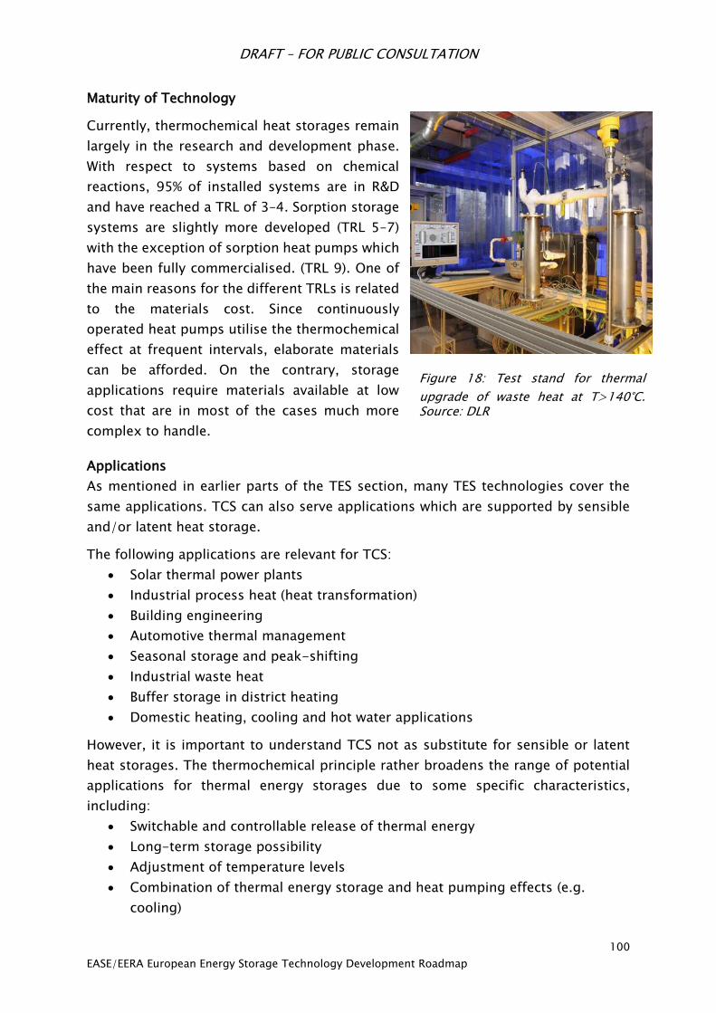
DRAFT – FOR PUBLIC CONSULTATION
100
EASE/EERA European Energy Storage Technology Development Roadmap
Maturity of Technology
Currently, thermochemical heat storages remain
largely in the research and development phase.
With respect to systems based on chemical
reactions, 95% of installed systems are in R&D
and have reached a TRL of 3–4. Sorption storage
systems are slightly more developed (TRL 5–7)
with the exception of sorption heat pumps which
have been fully commercialised. (TRL 9). One of
the main reasons for the different TRLs is related
to the materials cost. Since continuously
operated heat pumps utilise the thermochemical
effect at frequent intervals, elaborate materials
can be afforded. On the contrary, storage
applications require materials available at low
cost that are in most of the cases much more
complex to handle.
Applications
As mentioned in earlier parts of the TES section, many TES technologies cover the
same applications. TCS can also serve applications which are supported by sensible
and/or latent heat storage.
The following applications are relevant for TCS:
Solar thermal power plants
Industrial process heat (heat transformation)
Building engineering
Automotive thermal management
Seasonal storage and peak-shifting
Industrial waste heat
Buffer storage in district heating
Domestic heating, cooling and hot water applications
However, it is important to understand TCS not as substitute for sensible or latent
heat storages. The thermochemical principle rather broadens the range of potential
applications for thermal energy storages due to some specific characteristics,
including:
Switchable and controllable release of thermal energy
Long-term storage possibility
Adjustment of temperature levels
Combination of thermal energy storage and heat pumping effects (e.g.
cooling)
Figure 18: Test stand for thermal
upgrade of waste heat at T>140°C. Source: DLR

DRAFT – FOR PUBLIC CONSULTATION
101
EASE/EERA European Energy Storage Technology Development Roadmap
Combination with atmosphere control (e.g. dehumidification) and thermal
energy storage and so forth
Consequently, thermochemical storages (or systems) could be seen as
thermal process technologies rather than thermal energy storages.
SET-Plan Targets
Target description
Development of novel or improved thermochemical materials (TCM)
Improved materials and systems for TES with TCM in buildings
Development of testing and characterisation techniques for TCM
TCM should be 4-times more compact than water at system level
Specific investment cost below 50 €/kWh
Increased system storage density for TCS
Identification of niche applications for TCS
Materials research focused on ensuring an appropriate reaction reproducibility in medium-large term
operation.
Development of appropriate storage concepts in order to maximise the reaction rates, heat transfer,
and reproducibility of the reaction.
Gaps in Research
There remains fundamental material research to be done in TCS that is unaddressed
by the SET-Plan targets. To begin with, the cycling stability of the bulk material must
be improved as well as the expansion of the reactive material. Despite the necessity
of material research, one of the largest gaps in TCS research is the focus on material
rather than reactor and system aspects. In order to raise the TRL of TCS and ultimately
create a commercialised product, attention needs to be refocused from material
aspects onto reactor aspects. This is somewhat reflected in the SET-Plan targets (e.g.
increased system storage density), however these targets remain primarily focused
on material development. Efforts should also be made to combine reactive and
sorption storages. Finally, a gap in research is the integration of TCS systems in
relation to energy system integration: for example, small scale TES on residential level
in combination with solar heating and electric heat pumps.
Research Priorities
As discussed above, the main challenge for this technology is the transition from
material research aspects to system aspects, like reaction control, reactor design and
process integration. Therefore, research should focus on inter-disciplinary aspects
of the technology, such as:
1. How does a material react in prototype scale in comparison to the mg-scale
normally used to determine material properties?

DRAFT – FOR PUBLIC CONSULTATION
102
EASE/EERA European Energy Storage Technology Development Roadmap
2. What are the potential efficiencies in a real environment in comparison to
prototypes operated in lab-scale?
3. Besides these effects related to increase of the TRL, following concrete
research aspects are crucial for the technology of thermochemical storages
4. Development of adjustable and simplified reactor concepts
5. Improved integration of gaseous reactants
6. Selection and advancement of the storage material–thermodynamics, kinetics,
cycling stability
7. Optimisation of complete reversibility, reactor design, cost of reactants as well
as reactor lifetime (e.g. corrosion issues), sizing and cost improvement
Recommendations for Research Funding, Infrastructure and Incentives
The development of TCS with stable and controllable discharging power as well as
the separation of power and capacity first needs fundamental research in order to
understand the superimposed processes of reaction/sorption as well as heat and
mass transfer. As this functionality is the key to prepare TCS - independent from the
application or the temperature level - for a broad market and the research on it is the
foundation for further developments, fundamental research projects should be
funded in a first step (approximately 3 projects at €1.5 million). However, comparable
efforts are necessary for fundamental but application-oriented research projects to
close the gap between material development on one side and reactor integration and
design on the other. Funding of relatively high TRL applications of relatively small
scale and modular TCS for buildings and dwellings towards market implementation
is needed. Demonstration of TCS as part of integrated systems (e.g. with solar heaters
and heat pumps) is also required. These projects are of the highest importance to
continuously push the state of development in order to derive guidelines for specified
fundamental research.
DRAFT – FOR PUBLIC CONSULTATION
103
EASE/EERA European Energy Storage Technology Development Roadmap
7. Market Design and Policy Recommendations The deployment of energy storage technologies in Europe does not depend on the
strength of R&D efforts alone. An enabling regulatory environment that allows energy
storage to compete on an equal basis with other flexibility providers will be essential
to sustained growth in the energy storage industry.
As alluded to at the end of Chapter 4, the regulatory framework at EU and Member
State level has not evolved to support the cost-efficient deployment of energy
storage. At the moment, a fair market design is lacking for energy storage systems.
This chapter posits policy recommendations for addressing some of the key
regulatory barriers to energy storage deployment which currently exist in the market.
7.1 Policy Recommendations
A first set of EASE policy recommendations has been addressed by the European
Commission’s proposed regulation on the internal market for electricity110, as well as
the proposed directive on common rules for the internal market in electricity111,
issued in November 2016. It is now the role of the European Parliament and the
European Council to enshrine these texts into community law and to complement
them with the principles below, so as to remove the remaining regulatory barriers
hampering the large-scale deployment of energy storage in Europe.
Recommendation 1:
Establish a definition of energy storage in the EU regulatory framework
(e.g., an amendment to the Electricity Directive)
A robust and broad definition is needed to create investment security for the
European industry. It must be clarified if cross-sectorial interfaces, e.g. electricity in
and heat, gas or fuel out, can be considered as energy storage or not. To include this
would allow the dynamic operation of the electricity grid with thermal, fuel or gas as
flexibility for downward regulation, while making the renewable energy from the
electricity sector available for the decarbonisation of other sectors.
The definition should reflect all types and applications of energy storage and not only
traditional technologies and uses, such as pumped hydro storage or batteries, in
order to allow for the development of new technologies. The same reasoning applies
to the applications energy storage may fulfil. A narrow view of the applications will
restrict energy storage to some limited applications, while a broader view will allow
110 European Commission: Regulation on the internal market for electricity, 2016.
http://ec.europa.eu/energy/sites/ener/files/documents/1_en_act_part1_v9.pdf
111 European Commission: Directive on common rules for the internal market in electricity, 2016.
http://ec.europa.eu/energy/sites/ener/files/documents/1_en_act_part1_v7_864.pdf
DRAFT – FOR PUBLIC CONSULTATION
104
EASE/EERA European Energy Storage Technology Development Roadmap
a myriad of applications to develop according to technological development and
system needs.
In this context, EASE broadly supports the definition of energy storage proposed in
the draft Electricity Directive:
“'energy storage' means, in the electricity system, deferring an amount of the
electricity that was generated to the moment of use, either as final energy
or converted into another energy carrier.”112
However, EASE proposes propose to replace the word “generated” with the word
“produced”, since an Energy Storage definition is not the place to address the
question of ownership (by defining energy storage as generation). Therefore, the
definition should read:
“'energy storage' means, in the electricity system, deferring an amount of the
electricity that was produced to the moment of use, either as final energy
or converted into another energy carrier.”
We believe that this definition is general and robust enough to establish the concept
firmly under European law. Specific, context related clarifications could emerge to
resolve precise points, where needed.
Recommendation 2:
Establish clarity on the rules under which energy storage can access markets – in
particular, the perceived inability of transmission system operators (TSOs) and
distribution system operators (DSOs) to own and operate energy storage.
The following is a position that EASE has developed regarding the ownership of
energy storage devices:
One cannot talk about ownership of energy storage by regulated entities in the
abstract; instead, positions can be expressed only relative to energy storage
applications, or services.
For energy storage applications deemed to be market services, e.g., arbitrage,
only market players should be allowed to own or operate energy storage
facilities for their provision. The market should reflect the system needs, which
would provide for efficient solutions.
Energy storage applications deemed to be infrastructure services, i.e., fulfilling
services which are today already used by regulated entities with other
112 European Commission: Directive on common rules for the internal market in electricity, 2016.
http://ec.europa.eu/energy/sites/ener/files/documents/1_en_act_part1_v7_864.pdf
DRAFT – FOR PUBLIC CONSULTATION
105
EASE/EERA European Energy Storage Technology Development Roadmap
technologies (e.g., by building a line), should be able to be delivered also with
energy storage devices.
Regarding the ownership of energy storage by regulated entities (e.g., for the
provision of system services) in the absence of competitive supply, i.e. if shown
that a market-based service procurement is not feasible, such ownership
should be exceptional and on a temporary basis, subject to a periodic review
of the situation. Unjustified market barriers for energy storage should be
removed.
And, as a general rule, regulated entities could be allowed to own energy
storage in this context only upon the approval of the relevant national
regulatory authority (NRA). In the longer term, the underlying reason for the
market failure should be identified and properly addressed.
This point is also addressed in the draft directive on the internal market for electricity,
but EASE believes that a regulated entity should not be banned from owning energy
storage devices in order to fulfil services that are already provided by this regulated
entity. As an example, to bring electricity from point A to point B a TSO is allowed to
build a line; in fact, the TSO’s only choice to increase capacity is to build a second
line. EASE believes that the capacity of the first line may be increased by allowing the
TSO to own an energy storage device for this specific service. National regulatory
authorities should address the question of whether TSO or DSO ownership of energy
storage devices would be economical and could trigger innovative business models.
Recommendation 3:
Eliminate unwarranted/double charging, in particular the application of final
consumption fees to energy storage given that it does not constitute final use of the
energy
Energy storage is not a load, it is storing energy for later use in the grid (e.g.,
providing transmission or distribution services, peak capacity or other ancillary
services). In this context, energy storage assets should not be allocated
consumption/demand charges at transmission and distribution levels. This is also
valid for network charges and for any kind of taxes that consumers/load would have
to pay.
Since this point is not addressed clearly in the above mentioned texts, it falls to the
European Parliament and the European Council to make sure that the laws of physics,
meaning a kWh can only be consumed once, are reflected in the legal framework,
meaning a kWh cannot be taxed twice as a consumer.
DRAFT – FOR PUBLIC CONSULTATION
106
EASE/EERA European Energy Storage Technology Development Roadmap
Recommendation 4:
Ensure the procurement of all energy and ancillary services is market-based
System services are not all procured on market based conditions in all EU Member
States. This creates a higher cost for the consumer and discriminates against
technologies that are not allowed to provide these services, even if the services would
be provided cheaper and more accurately.
In Italy, for example, the procurement of frequency control response (FCR) is not
market based. This, therefore, increases the costs of these FRC services for the
consumer. A study quantifying these costs found that a given Italian coal plant would
save €1.7 million per year by providing the service with energy storage, such as
batteries.113 By addressing this point in the recast electricity directive, the European
Commission has set the first steps, which now must be implemented using secondary
legislation such as the Network Codes.
Recommendation 5:
Establishing energy storage as a separate asset class
EASE calls upon EU policy makers to go further than the proposed regulation and
directive by establishing energy storage as a separate asset class, as called for by the
European Parliament.114 Energy storage should be recognised as the fourth element
of the energy system (alongside generation, transport (transmission/distribution),
and consumption). This would prevent energy storage from being classified as either
generation or consumption – or as both. Such a fourth element status would eliminate
any ambiguity that results from the historical market design stemming from a
centralised energy system where everything fit into one of the three categories. It
would also allow for a clear framework specific to energy storage, clarifying amongst
others the unwarranted double charging (including levies and taxes) on energy
storage devices and the ownership of energy storage facilities.
7.2 Conclusions
The above set of barriers is illustrative and not exhaustive; there are numerous other
entry barriers which could be enumerated here. The rapid development and
deployment of energy storage technologies, as well as their integration into the grid,
could be supported with broader regulatory reform and the elimination of these
113 RSE: Battery Energy Storage System applications for the provision of dispatching services: cost-
benefit analyses. Presentation by Silvia Canavese at POWER-GEN Europe conference, June 2016. 114 European Parliament Report: Towards a New Energy Market Design (2015/2322(INI)), 2016.
http://www.europarl.europa.eu/sides/getDoc.do?pubRef=-//EP//TEXT+REPORT+A8-2016-
0214+0+DOC+XML+V0//EN

DRAFT – FOR PUBLIC CONSULTATION
107
EASE/EERA European Energy Storage Technology Development Roadmap
barriers. When discussing R&I efforts, it is important to underline that a supportive
regulatory framework for storage is vitally important to the market roll-out of
innovative storage technologies.

DRAFT – FOR PUBLIC CONSULTATION
108
EASE/EERA European Energy Storage Technology Development Roadmap
8. Recommendations and Proposed Timeline for
Activities
The transition to a sustainable, low-carbon energy system is already well underway
in Europe. Energy storage is poised to play a vital role in supporting that transition,
although the size of its contribution depends on further technological developments
and cost reductions for storage. An effective and coordinated R&D effort in Europe
can support the burgeoning storage industry, particularly if coupled with a promising
regulatory environment and increased private investment for commercialisation.
Given the large range of storage technologies, which are at varying TRLs and suitable
to many different applications, prioritisation of R&D efforts in the energy storage
domain is extraordinarily difficult. The below recommendations take into account the
most important cross-cutting priorities mentioned for all energy storage
technologies; the most promising business cases and applications for storage, both
today and in the near future; and the most pressing issues in the energy transition
that could be addressed through storage (e.g. integrating variable RES, decarbonising
heating and cooling and transport).
8.1 Identification of Energy Storage R&D Priorities
In chapter 6, we identified research priorities specific to each energy storage
technology. One common theme is the need to reduce the cost of storage: this is
considered one of the top priorities to address for each family of storage
technologies. This can be done through a focus on materials research, manufacturing
processes, and efforts to improve integration with other system components. Another
overarching theme is the need to research energy storage business cases and to
clarify the technical requirements and economics of aggregating different energy
storage services.
To identify R&D priorities for the short, medium, and long-term, it is helpful to
consider the promising business cases and applications for energy storage in those
timescales. In the coming years, the most promising energy storage applications,
based on commercial business cases, are in the short-term electricity balancing
market. Ancillary services, including new ones being proposed by the UK and Ireland,
are already offered by energy storage devices.
In a medium-term perspective (5-10 years), not only ancillary services but also
energy arbitrage based on stored energy could be a valuable application. Investment
deferral, both at the DSO and TSO levels, could be a further promising application,
but is dependent on solving the ownership question. Self-consumption and storage
of renewable electricity could also become more wide-spread.

DRAFT – FOR PUBLIC CONSULTATION
109
EASE/EERA European Energy Storage Technology Development Roadmap
20 years from now, energy storage will likely play an important role in linking the
electricity system closely to its neighbouring sectors in the energy system, thereby
decarbonising them. Private as well as industrial heat demand are obvious candidates
for future supply from the electricity system and the transport sector will undoubtedly
– although perhaps at a slower rate – be shifted to supply by energy based on
sustainable electricity. Energy storage applications able to support the
decarbonisation of heating and cooling and transport will become increasingly
valuable.
8.2 Recommendations and Timeline
Below, we summarise the R&D priorities we consider most pressing for the industry
as a whole. We situate these along a rough timeline, based on an assessment of the
most pressing needs and of which efforts are likely to yield the most promising
returns for the energy system.
We recommend the following timeline for energy storage RD&D projects in Europe:
Within the next 2 years:
Set up European demonstration and pilot programmes focusing on grid
integration of relatively mature energy storage technologies. These programmes
will be necessary to support the deployment of the technologies needed within a
short timeframe to integrate growing shares of RES. Pilot programmes would be
particularly valuable for chemical storage, grid-scale battery storage, new
advancements of PHS technology in terms of flexibility or development potential,
and intermediate heat storage for adiabatic CAES. Such demonstration projects
will, within 5-10 years, yield valuable experience for design and manufacturing
processes for cost-effective large-scale industrial production. Demonstration
projects will also allow for collecting information on grid integration of energy
storage devices.
Support materials and equipment research to allow improving and understanding
performance of crucial components and parts in energy storage facilities. Such
efforts will have impact on both economy, performance and flexibility of storage
technologies. In particular, research on materials for energy storage technologies
could have an important effect on reducing storage system cost. This would
include low cost materials for hydrogen storage as well as thermal storage, novel
materials for completely new electrochemical systems (e.g., metal-air, liquid
batteries, Mg-based batteries, organic batteries,…), and nitride and sulphide
materials for capacitors.

DRAFT – FOR PUBLIC CONSULTATION
110
EASE/EERA European Energy Storage Technology Development Roadmap
Designate energy storage as an Important Project of Common European Interest
(IPCEI)115. IPCEIs aim to encourage Member States to direct public spending to
large projects that make a clear contribution to economic growth, jobs, and
competitiveness of European industries. IPCEIs can receive several forms of
support (e.g., repayable advances, loans, guarantees or grants from Member
States), aid for the first industrial deployment of an R&D, and are exempt from
state aid measures. Designating energy storage as an IPCEI could help build a
strong European manufacturing base for key energy storage technologies that
could allow Europe to be globally competitive.
Carry out intensive research efforts at the grid integration level in order to
decrease storage system costs and to facilitate the aggregation of different
applications. This includes software development to improve modelling and
control the use of energy storage technologies.
Identify possible market models/use cases able to guarantee the economic
feasibility of energy storage devices and assess how markets could be improved
in order to allow the full deployment of energy storage. This should be done in a
joint effort between the EU Member States to secure the highest degree of
alignment.
Develop a strategic energy storage plan for Europe, detailing how to conduct
strategic development and planning of energy storage potential in Europe,
alongside strategic plans for infrastructure development, supply-side
development and demand-response options in the most cost-effective way. Plans
should include a regional/local assessment of specific energy storage potential
and needs given specific local circumstances regarding supply, demand, and
energy infrastructure.
Initiate a long-term, coordinated research effort among leading private
companies and research laboratories across Europe with common expertise
related to energy storage technologies.
Sustain laboratory scale (or equivalent) development and assessment of new, still
unproven, energy storage ideas and concepts to allow subsequent qualified
judgment of their potential and viability for further support and applicability. Such
efforts may be high-risk, but they could allow for new advancements and novel
ideas not even perceived today.
115 See European Commission: State aid: Commission adopts new rules to support important projects of
common European interest, 13 June 2014. http://europa.eu/rapid/press-release_IP-14-673_en.htm
DRAFT – FOR PUBLIC CONSULTATION
111
EASE/EERA European Energy Storage Technology Development Roadmap
Within the next 2-5 years:
Analyse degradation processes related to diverse duty cycles (including
modelling) to allow for predictive maintenance, increased reliability, and improved
designs and manufacturing processes.
Study system integration, focusing on how gas, electricity, heat, and other
infrastructures (e.g. refuelling infrastructure) can be combined and
complemented with storage of gas, electricity, heat, and/or fuels.
Systematically demonstrate the ways in which energy storage can provide energy
services and monetise the added value to the energy system. Demonstrating the
effective use of energy storage devices not only from a technical but also from an
economic point of view would greatly facilitate their deployment. Such an
assessment could consider energy storage installations at each location in the grid
in order to identify at which point of the grid energy storage could provide
different applications in the most cost-effective way.
Investigate new designs for energy storage and hybrid technologies and analyse
requirements for optimal integration.
Continue basic materials research initiated in the first 2-year period.
Within the next 5-10 years:
Support new large-scale demonstration projects based on the experience gained
from the first phase projects and including results obtained from materials
research and modelling efforts.
Continue basic materials research and evaluation of new ideas and continuously
check R&D status against application requirements
Support communication and interaction of different storage assets in the grid for
supplying ancillary services and load shifting.
Conduct research on energy storage in relation to the expected expansion of EVs,
including vehicle-to-grid services and the use of second-hand EV batteries for
stationary applications.
The above recommendations attempt to consolidate the many R&D priorities and
considerations enumerated for each energy storage technology. They are based on
assumptions on the evolution of the electricity system and energy storage
technologies in Europe. However, technological breakthroughs in storage
technologies and/or other flexibility options may completely change the basis for the
present recommendations.

DRAFT – FOR PUBLIC CONSULTATION
112
EASE/EERA European Energy Storage Technology Development Roadmap
Moreover, it is important to note that the recommendations given in the present
Roadmap should not preclude supplementary R&D interest and resources in other
technologies that are not presently believed to hold a commercial potential in the 10-
20 year period.

DRAFT – FOR PUBLIC CONSULTATION
113
EASE/EERA European Energy Storage Technology Development Roadmap
LIST OF FIGURES
Figure 1: Worldwide installed energy storage capacity ........................................................ 17
Figure 2: Overview of energy storage applications. Source: EASE ........................................ 18
Figure 3: Overview of different energy storage technologies ............................................... 24
Figure 4: Technical maturity of chemical storage components ............................................ 34
Figure 5: Battery market growth (MWh) 1990-2015, Avicenne Energy, 2016 ....................... 42
Figure 6: compilation by EMIRI, EUROBAT, EASE, and Technofi, 2016 .................................. 43
Figure 7: Cost estimates and future projections for electric vehicle battery packs, measured
in US $ per kilowatt hour of capacity. Each mark on the chart represents a documented
estimate reviewed by the study. Source: Nykvist et al. (2015) ............................................. 44
Figure 8: Energy storage applications segmented by discharge time ................................... 45
Figure 9: Tentative Roadmap for supercapacitors with vision to 2030 (prepared by CNR-ITAE
from). .................................................................................................................................. 55
Figure 10 - SMES buffering of mechanical, chemical, electrochemical or cryogenic Energy
Storage Systems .................................................................................................................. 57
Figure 11 - LIQHYSMES Storage Unit based on hydrogen for long term energy storage and
SMES for short term storage ................................................................................................ 57
Figure 12: LAES mode of operation ..................................................................................... 73
Figure 13: Principle of a Pumped Hydro Storage plant ......................................................... 79
Figure 1 - Timeframes for modern advanced PHS unit regulation ....................................... 81
Figure 15: Crescent Dunes molten salt storage tank ........................................................... 87
Figure 16: aerial view of Crescent Dunes molten salt storage (Source: COBRA) ................... 88
Figure 17: Latent storage system with 700 kW power, 1h storage capacity, Source: DLR .... 95
Figure 18: Test stand for thermal upgrade of waste heat at T>140°C. Source: DLR ........... 100
LIST OF TABLES
Table 1: SET Plan targets Alkaline Technology ..................................................................... 35
Table 2: SET Plan targets PEM Technology ........................................................................... 35
Table 3: SET Plan targets Solid Oxide Technology ............................................................... 36
Table 4: SET Plan targets Plasmology CO2 ........................................................................... 36
Table 5: SET Plan targets Hydrogen Storage Technologies .................................................. 37
Table 6: Status of development of major electrochemical storage systems for grid applications
........................................................................................................................................... 41
DRAFT – FOR PUBLIC CONSULTATION
114
EASE/EERA European Energy Storage Technology Development Roadmap
Table 7: Comparison among different electrochemical storage systems for the different
discharge times corresponding to the different energy storage applications ....................... 45
Table 8: SET Plan targets for electrochemical storage.......................................................... 46
Table 9: SET Plan targets for supercapacitor* technologies towards 2030 and beyond ....... 53
Table 10: Economic SET Plan targets for supercapacitor technology towards 2030 ............. 53
Table 11 - Targets for SMES materials towards 2030 and beyond ....................................... 59
Table 12: Targets for SMES materials, technology and systems towards 2030 and beyond . 60
Table 13 Application potentials of CAES related technology ................................................ 65
Table 14. The theoretical values of the maximum energy efficiency .................................... 66
Table 15: SET-Plan targets .................................................................................................. 70
Table 16: SET-Plan targets .................................................................................................. 76
Table 17 – PHS features (VS = variable-speed, TS = Ternary Set) ........................................ 80
Table 18 - SET Plan targets for hydro energy storage technologies towards 2030 and beyond
........................................................................................................................................... 82
Table 19 - Estimated R&D needs for hydro energy storage technologies ............................ 85
Table 20: Applicability of thermal storage technologies for different applications .............. 87
Table 21: Characteristics of low/high temperature sensible energy storage technologies ... 88
Table 22: Characteristics of LHS technologies ..................................................................... 95
Table 23: Characteristics of TCS technologies ..................................................................... 99