erosion protection for soil slopes along ... contract report erosion protection for soil slopes...
TRANSCRIPT

FINALCONTRACT REPORT
EROSION PROTECTIONFOR SOIL SLOPES
ALONG VIRGINIA'S HIGHWAYS
JESSEE A. SCARBOROUGHGEORGE M. FILZ
JAMES K. MITCHELLand
THOMAS L. BRANDON
Via Department of Civil EngineeringVirginia Tech
Blacksburg, Virginia
V~I·R·G·I·N·I·A
TRANSPORTATION RESEARCH COUNCIL
VIRGINIA TRANSPORTATION RESEARCH COUNCIL

Standard Title Page - Report on State ProjectReport No. Report Date
VTRC 01-CR3 October 2000
No. Pages
99
Type Report:Final
Period Covered:1/99-6/99
Project No.:VPC 0051101
Contract No.99-1017-11
Title:Erosion Protection for Soil Slopes Along Virginia's Highways
KeyWords:Soil slopes, erosion, erosion control,erosion protection, USLEt-----------------------------------IAuthors: Jessee A. Scarborough, George M. Filz, James K. Mitchell, and
Thomas L. Brandon
Performing Organization Name and Address:
Virginia TechBlacksburg, VA 24061-0105Sponsoring Agencies ' Name and Address
Virginia Department of Transportation1401 E. Broad StreetRichmond, VA 23219Supplementary Notes
Abstract
A survey of the state of practice for designing slope erosion control measures within VDOT's nine districts has been conducted.On the basis of the survey, it is clear that there are no specific design procedures currently in use within VDOT for dealing withslope erosion. VDOT designers generally try to limit erosion by diverting runoff from adjacent areas, controlling concentratedflows on slopes, and establishing vegetation on slopes as quickly as possible. In addition, the Federal Highway Administration(FHWA) and the Departments of Transportation in states surrounding Virginia (Maryland, West Virginia, Kentucky, Tennessee,and North Carolina) were contacted. The state of practice for the FHWA and for these states appears to be similar to that used byVDOT.
A review of the literature for soil erosion was performed. The universal soil loss equation (USLE), an empirical equationdeveloped by the U.S. Department of Agriculture, was found to provide the best available quantitative tool for evaluating factorscontrolling the erosion process and determining what level ofprotection is appropriate. The authors recommend that the USLE beused to supplement VDOT's current principle-based design practices.

FINAL CONTRACT REPORT
EROSION PROTECTION FOR SOIL SLOPESALONG VIRGINIA'S HIGHWAYS
Jessee A. Scarborough, George M. Filz, James K. Mitchell, and Thomas L. BrandonVia Department of Civil Engineering
Virginia TechBlacksburg, Virginia
(The opinions, findings, and conclusions expressed in thisreport are those of the authors and not necessarily those of
the sponsoring agency.)
Project MonitorsEdward J. Hoppe, Virginia Transportation Research Council
Stanley L. Hite, Virginia Department of Transportation
Contract Research Sponsored byVirginia Transportation Research Council
Virginia Transportation Research Council(A Cooperative Organization Sponsored Jointly by the
Virginia Department of Transportation andthe University of Virginia)
October 2000VTRC 01-CR3

NOTICE
The project that is the subject of this report was done under contract for the VirginiaDepartment of Transportation and the Virginia Transportation Research Council. Theopinions and conclusions expressed or implied are those of the contractors, and,although they have been accepted as appropriate by the project monitors, they are notnecessarily those of the Virginia Transportation Research Councilor the VirginiaDepartment of Transportation.
Each contract report is peer reviewed and accepted for publication by the ResearchCouncil staffwith expertise in related technical areas. Final editing and proofreadingof the report are performed by the contractor.
Copyright 2000, Virginia Department of Transportation.
ii

ABSTRACT
Erosion of soil slopes can undermine pavements and other structures, create safetyhazards, and harm the environment. Repair of eroded soil slopes can be problematic because ofdifficult access and working conditions. Such difficulties can result in high costs for sloperepair. Effective erosion protection measures can prevent or reduce the scope of such problems.The Virginia Department of Transportation (VDOT), through the Virginia TransportationResearch Council (VTRC), requested that Virginia Tech investigate and report on guidelines forselecting appropriate erosion protection measures.
A survey of the state ofpractice for designing erosion control measures within VDOT'snine districts has been conducted. On the basis of the survey, it is clear that there are no specificdesign procedures currently in use within VDOT for dealing with slope erosion. However, slopeerosion control was perceived as a very important issue, and a general design philosophy wasfound. Currently, VDOT designers generally try to limit erosion by diverting runoff fromadjacent areas, controlling concentrated flows on slopes, and establishing vegetation on slopes asquickly as possible. In addition, the Federal Highway Administration (FHWA) and theDepartments of Transportation in the states surrounding Virginia (Maryland, West Virginia,Kentucky, Tennessee, and North Carolina) were contacted. The state ofpractice for the FHWAand for these states appears to be similar to that used by VDOT.
A review of the literature for soil erosion was performed. Design methods for slopeerosion control are not well developed. The universal soil loss equation (USLE), an empiricalequation developed by the U.S. Department of Agriculture, provides the best availablequantitative tool for evaluating factors controlling the erosion process and determining whatlevel ofprotection is appropriate. A design example using the USLE is provided.
To the authors' knowledge, the USLE is not used as the primary tool for slope erosiondesign by any state department of transportation, or by the FHWA. For this reason, it is not therecommendation of this study that VDOT adopt the USLE as its primary method for slopeerosion design. Instead, the authors recommend that the USLE be used to supplement VDOT'scurrent principle based design practices. The authors also recommend that VDOT's principlebased design approach be improved by development of a systematic method for documentingand communicating throughout VDOT the performance of erosion control measures.
iii
FINAL CONTRACT REPORT
EROSION PROTECTION FOR SOIL SLOPES ALONG VIRGINIA'S HIGHWAYS
Jessee A. Scarborough, George M. Filz, James K. Mitchell, and Thomas L. BrandonVia Department of Civil Engineering
Virginia TechBlacksburg, Virginia
INTRODUCTION
The erosion of soil slopes along Virginia's highways is a serious problem. Erosion ofsoil slopes can create safety hazards, such as undermined pavements. Environmental quality canalso be reduced by the sediments from eroded slopes. Moreover, repair of eroded slopes can beproblematic due to restricted access and difficult working conditions. Such difficulties can resultin high costs for slope repair. Effective erosion protection can prevent or reduce the magnitudeof these problems. However, selection of appropriate erosion control protection is difficultbecause design methods are not well developed.
The Virginia Department of Transportation (VDOT), through the Virginia TransportationResearch Council (VTRC), requested that Virginia Tech investigate erosion protection for soilslopes along Virginia's highways. There is a concurrent, but separate, VTRC sponsored researchproject for erosion of roadside channels and ditches; the two projects should not be confused.The objective of this research is to recommend approaches for selecting appropriate erosionprotection measures for soil slopes. To accomplish this objective, a literature review for slopeerosion and a survey of the state ofpractice were performed.
The following three sections of this report present: 1) the methods used for the research,2) the research results and discussion, and 3) conclusions and recommendations. Because themethods used to conduct this research were limited to a literature review and interviews, themethods section is short. The results and discussion section includes the results of the literaturereview and the survey. Subsections based on the literature review include fundamentals of soilerosion control, principles of soil erosion control, and methods of soil erosion control.Additional subsections present the results of the state ofpractice survey. This includes asummary of interviews with VDOT personnel and a description of erosion control practices insurrounding states. The last subsection of the results and discussion section presents proceduresfor selecting soil erosion control measures. The conclusions and recommendations sectionincludes a summary of the work accomplished, findings, and recommendations.
The report includes three appendices. Appendix A contains the questionnaire used forinterviews. Appendix B contains VDOT guidance for erosion control blankets and mats.Appendix C contains a form for collecting information about slope erosion control.
1

METHODS
The methods used to conduct this research consisted of performing a literature review andinterviewing individuals who deal with erosion control. The information collected was thensynthesized to produce this report.
The interviews were conducted with personnel from VDOT and from Departments ofTransportation (DOTs) in the surrounding states ofMaryland, West Virginia, Kentucky,Tennessee, and North Carolina. Personnel from the Federal Highway Administration were alsocontacted. The interview questions are presented in Appendix A
RESULTS AND DISCUSSION
This section of the report presents and discusses the results of the literature review and theinterviews. First, the fundamentals of soil erosion are discussed and the USLE is presented.Next, ten principles of soil erosion are discussed. This is followed by a discussion of availablemethods for soil erosion control. Next, the interviews with personnel from VDOT, the DOTsfrom surrounding states, and the FHWA are summarized. Finally, several approaches forselecting erosion control methods are discussed in this section of the report.
Fundamentals of Soil Erosion
Ingold and Thomson (1990) tell us that the word erosion is derived from the Latin,erodere, to gnaw, or erosus, to eat away. Soil erosion is the removal of soil by wind, water orice. For the purpose of developing guidelines for selecting methods for erosion control for slopes,this report focuses on the agency ofwater, in particular, rainfall and runoff
Two mechanisms are involved with soil erosion on slopes: 1) detachment and 2)transport. Rainfall erosion begins with the impact of a raindrop on the ground surface. Thekinetic energy of raindrop impact can dislodge and move soil particles, beginning the process ofsoil erosion. After rain falls on the ground surface, it becomes runoff The initial distributed flowof runoff across the ground is known as sheet flow. As soil particles are removed and transportedby the flow, small channels known as rills form. Larger and deeper flow channels are gullies.The higher velocity of flow and greater depth of flow in the rills and gullies provide the energyrequired for transporting soil particles. Figure 1 illustrates these types of erosion on a slope.
Figure 1 also shows the erosion of stream channels and banks. While stream and ditcherosion can be significant problems in their own right, they are not the subject of this report.VTRC is sponsoring a separate, but concurrent, research project on the erosion of roadsidechannels and ditches.
There are five fundamental factors that influence the erosion of soil slopes under theagency of water. These are embodied in the Universal Soil Loss Equation, which is discussednext.
2

SHEETEROSION
RIU AND GULLYEROSION
.CHANNEL EROSION
.0
STREAN FlOW"
Figure 1 - Types of rainfall/runoff erosion (Virginia, 1992)
Universal Soil Loss Equation
Five factors influence soil erosion on slopes:
1) the duration and intensity of rainfall,2) the type of soil and its erodibility,3) the topography of the slope, its length and steepness,4) the type and extent of vegetative cover on the slope, and5) the type and extent of other erosion control methods and practices.
3

Wischmeier and Smith (1978) developed the Universal Soil Loss Equation (USLE) as anempirical tool to predict the effect ofvariation in the five basic factors on the amount of soilerosion. The USLE can be stated as the following:
A=RxKxLxSxCxP (1)
where A is the computed soil loss rate per unit area in tons per acre per year, R is the rainfall andrunoff factor, K is the soil erodibility factor, L is slope length factor, S is the slope steepnessfactor, C is the cover factor, and P is the practice factor.
The USLE is an empirical equation developed in English units. When using the USLEwith metric units, it is recommended that unit conversions not be performed until the result isobtained. The soil loss rate can be easily converted from tons per acre per year to kilograms persquare meter per year by multiplying by 0.226 (i.e., 1 ton/acre/year = 0.226 kg/m2/year).Hereafter, primary use of metric units will be made, the English equivalents follow in parenthesis.
Development of the USLE began in the 1940's (Wischmeier and Smith, 1978). Theoriginal version that related erosion to slope length and inclination was known as the slope-practice method. Subsequent modification added factors for vegetative cover and conservationpractices. A similar equation, known as the Corn Belt Equation, contained parameters for soiltype and land management practices. These two equations were combined in 1946 as theMusgrave Equation for estimating the gross erosion within a watershed. In the early 1950's, themethods were modified and became known as the Universal Soil Loss Equation (USLE). A 20year study was undertaken to calibrate the USLE based on the erosion ofstandard unit plots. Thestandard unit plot is bare ground 22.13 meters (72.6 ft) long at a slope of9 percent, plowed incontinuous fallow (i.e., tilled up and down the slope). During the 1970's with accumulation of10,000 plot years of data, the USLE was published in Agricultural Handbook No. 537, PredictingRainfall Erosion Losses, A Guide to Conservation Planning by Wischmeier and Smith (1978). In1997, the U.S. Department of Agriculture published Agricultural Handbook No. 703, PredictingSoil Erosion by Water: A Guide to Conservation Planning with the Revised Universal SlJil LossEquation (RUSLE). This guide uses the same empirical equation, with modification of theindividual factors to reflect additional data (USDA, 1997). Since 1978, the USLE or itsderivatives have remained the standard method for evaluating slope soil erosion on agriculturalland.
Rainfall and runofffactor, R
The rainfall and runoff factor, R, is based on the raindrop impact effect and on the amountand rate of runoff Average annual values of the R-factor are normally used and can be obtainedfrom an isoerodent map, such as shown in Figure 2, which is an isoerodent map for theCommonwealth of Virginia.
For a single storm event, the R-factor is proportional to the product of the rainfall kineticenergy rate and the maximum 30-minute rainfall intensity. Table 1 is a summary of typical valuesof the kinetic energy rate for various rainfall intensities in a single storm. This illustration of the
4

variation in the energy applied during rainfall events of differing intensities is important because itclearly shows that heavy rains produce the most erosion.
Table 1 - Kinetic energy and velocity of raindrops for various rainfall intensities (after Biotechnical SlopeProtection and Erosion Control, D. H. Gray and A. T. Leiser, copyright © 1982, Van Nostrand Reinhold.Reprinted by permission of Van Nostrand Reinhold).
Raindrop Drops per Kineticmedian Velocity square meter energy
Intensity diameter of fall per second rateRainfall (mmlhour) (mm) (m/sec) [m2/sec] (J/ m2/hour)
Fog 0.13 0.01 3.05 x 10⁻³ 67,425,135 6.03 x ~0-7
Mist 0.05 0.10 0.21 27,017 1.14 x 10⁻³
Drizzle 0.25 0.96 4.11 151 2.]9Light rain 1.02 1.24 4.79 280 11.8
Moderate rain 3.81 1.60 5.70 495 63.3Heavy rain 15.24 2.05 6.71 495 185
Excessive rain 40.64 2.40 7.32 818 582Cloudburst 101.6 2.85 7.89 1,216 1,680Cloudburst 101.6 4.00 8.90 441 2,150Cloudburst 101.6 6.00 9.30 129 2,320
Wischmeier and Smith (1978) provide values ofR for four cites iIi Virginia. The R valuesgiven in Table 2 are annual values with probabilities of non-exceedance of 50, 75 and 95 percentduring the 22-year observation period. Table 3 contains the expected magnitude ofR for singlestorms with a recurrence interval of 1, 2, 5, 10 and 20 years.
Table 2 - Ran~,e of the annual rainfall factor, R (after Wischmeier and Smith, 1978).Value of the rainfall factor, R
Observed range 50 percent noo- 75 percent non- 95 percent non-City 22-year period exceedance exceedance exceedance
Blacksburg 81 -245 126 168 221Lynchburg 64 - 366 164 232 324Richmond 102 - 373 208 275 361Roanoke 78 - 283 129 176 237
Table 3 - Expected magnitude of single storm rainfall factor, R (after Wischmeierand Smith, 1978).
Value of the rainfall factor, R1- year 2-year 5-year 10-year 20-year
recurrence recurrence recurrence recurrence recurrenceCity interval interval interval interval interval
Blacksburg 23 31 41 48 56Lynchburg 31 45 66 83 103Richmond 46 63 86 102 125Roanoke 23 33 48 61 73
5

The
figu
resh
ows
aver
age
annu
alco
ntou
rso
fthe
R-f
acto
rfr
omth
eU
SL
Ein
foot
-ton
spe
rac
re.
Fig
ure
2-
Isoe
rode
ntm
apfo
rV
irgi
nia
(aft
erW
isch
mei
ran
dSm
ith,
1978
)
6
,<,;,0 ,1<
';' fl,OO

Soil erodibility factor, K
The soil erodibility factor, K, is an empirical value. The K-factor is based on the erosionof a unit plot. The unit plot provides the reference condition for evaluating erosion in the USLE.The unit plot is bare ground 22.13 meters (72.6 ft) long at a slope of9 percent, plowed incontinuous fallow (i.e., tilled up and down the slope). The K-factor has been foundexperimentally to vary between 0.02 and 0.69 (Gray and Leiser, 1982).
Wischmeir and Smith (1978) developed an erodibility nomograph relating soilcharacteristics to the K-factor. They show five factors contributing to soil erodibility:
1) percent of silt and very fine sand (0.002 - 0.10 mm grain size),2) percent sand (0.10 - 2.0 mm grain size),3) percent organic matter,4) soil structure, and5) permeability.
Their nomograph is shown in Figure 3.
Gray and Sotir (1996) suggest this hierarchy of erodibility based on the Unified SoilClassification System:
Most erodibleML> SM> SC >MH> OL »
Least erodibleCL > CH > GM > SW > GP > GW
where the most erodible soils are ML, silt; SM, silty sand; SC; clayey sand; MH, elastic silt; andOL, organic silt and clay. Soils with less erodibility are CL, lean clay; CH, fat clay; GM, siltygravel; SW, well-graded sand; GP, poorly graded gravel; and GW, well-graded gravel. Thisassessment of soil erodibility is based on the engineering characteristics of soils derived from theirgrain size and plasticity. However, the relationship between the K-factor, developed fromagricultural classifications of soils, and the engineering properties and classifications of soils is notwell defined. Gray and Sotir (1996) indicate that the following factors contribute to soilerodibility:
1) Grain size: Erodibility is low for well-graded gravels and high for uniform silts and finesands.
2) Void ratio: Denser soils with a low void ratio are less vulnerable to erosion.3) Organic content: Erodibility is low for soils with a high organic content due to the
interconnection of organic fibers in the soil.4) Antecedent moisture: Soils with a high antecedent moisture content are less susceptible to
erosIon.5) Clay content and type: Erodibility increases with decreasing clay content. There is
greater erodibility with increasing sodium adsorption ratio and decreasing ionic strength ofthe eroding water.
7

•I.
••
".,••
S.",.
....
...
t...
....
S-
f.t
.Z
-'e
,.....
I.,.",
~
~
~'l/
.._--
-
•S
OL
STRU
CTU
RE
•I-we
',,..
""o
"vlo
r
2-te
"."0
'"'''
'3·
•••
Of
co
.r••
I"""
'"4
.bl.
ck
,.p,.
t,.o
rIf
t•••
,y•
~ ~40'
o.
'0I
....
.e
CA
lI«
-1
"•
... U ~ ,..3
0r--'·:M··'·!P~·_'"
c«
,..
...-
v»
:::; Ii e.20
I.-..~C
5:
•I
a: '"• ..J o (II
.70
~,
.
PRO
CE
DU
RE
:E
nter
scal
eat
left
and
proc
ede
topo
ints
repr
esen
ting
the
soil'
spe
rcen
tsan
d.pe
rcen
torg
anic
mat
ter.
stru
ctur
e,an
dpe
rmea
bilit
y,in
that
sequ
ence
.In
terp
olat
ebe
twee
npl
oued
curv
es.
The
dotte
dlin
eill
ustra
tes
the
proc
edur
e.
10"
-.....
....
:s:
II
II
1«
"A
.
30
I"..'
P4
""'"
90
tI
II
II
1"-
=-.
."Y
I
10
0"1
11
'11
11
11
11
11
11
11
11
11
11
11
11
11
11
11
11
11
11
11
11
11
1'1
11
11
11
11
11
11
11
11
1.1
11
11
1.1
••
1
peI
.50
" ~
~!
~40
iA
O=
wI
!!
550
.~~.~
>~
+f
~60I
.20
iii .... Z &AI~70r=
~
Fig
ure
3-
Nom
ogra
phfo
rth
eso
iler
odib
ilit
yfa
ctor
,K
(Wis
chm
eir
and
Sm
ith,
1978
)
8

There is substantial uncertainty regarding the last factor cited, the effects of clay contentand the type of clay on erodibility. The sodium adsorption ratio has been used as an index oferodibility because sodium is an easily replaceable cation, while the ionic strength of water reflectsthe availability of cations for replacement. As shown above, clays are generally thought of asbeing less erodible. However, dispersive clays are known to be highly susceptible to erosion.
At least one experimental study highlights the difficulty in using clay type and content as aguide for assessing soil erodibility. Shaikh et al. (1987) conducted erosion testing of three clays:sodium montmorillonite, kaolinite, and calcium montmorillonite. Calcium is a cation lessreplaceable than sodium. Kaolinite is a type of clay noted for low susceptibility for cationreplacement. It was found that sodium montmorillonite with a high sodium adsorption ratio (19.8meq/liter) was less susceptible to erosion than a calcium montmorillonite with a low sodium .adsorption ratio (0.4 meq/liter). The kaolinite tested (with a sodium absorption ratio of 0.5meq/liter) had the same susceptibility to erosion as the sodium montmorillonite.
In addition, the shear strength of soil has been cited as a factor in reducing erodibility.Cohesion, a component of shear strength often associated with clay soils, has been cited asresisting the detachment of soil for transport. However, the experimental work of Shaikh et al.(1987) also found that the Torvane shear strength of the three clays tested did not correlate witherodibility.
The erodibility of gravels, sands, and silts is better understood. Duffy and Hatzell (1991)reported on the erodibility of gravels and sands. They found that the ground surface of sandysoils becomes armored against raindrop impact when half the soil particles are larger than a U.S.No.4 sieve. This means that gravel size particles are able to protect sand size particles from theerosive force associated with raindrop impact. They also found that for 2H: 1V slopes, largerdiameter, angular soil particles can resist rill erosion. The use of very large particles, such as usedfor rip-rap, were not required. Particles as small as 38.1 mm (1.5 in) in diameter with a shapefactor greater than 2.0 resisted rill erosion on the 2H: 1V test slope. The shape factor is the ratioof the longest to shortest particle dimensions. This illustrates the resistance of gravels to theerosive force associated with the transport mechanism of slope erosion. Armstrong and Wall(1991) conducted laboratory testing on the erodibility of a sandy silt. They found excellentagreement between the test results (K=0.25 to 0.26) and the K-factor found from Wischmeier andSmith's nomograph (K = 0.26). Therefore, it seems reasonable to use the nomograph in Figure 3for evaluating the erodibility ofgravels, sands, and silts.
Topographic factor, LS
The length and inclination (or steepness) of a slope affects the amount of soil erosion. Thecontributions of slope length factor, L, and the slope steepness, S, were separately analyzed byWischmeier and Smith (1978) based on the unit plot described above. Empirical equations weredeveloped to estimate values for Land S.
9

Values of the length factor, L, are primarily related to the slope length, but also depend onthe soil type and inclination of the slope. USDA (1997) provides an empirical equation tocalculate the L-factor for slopes steeper than 9 percent (most slopes along highways have aninclination greater than 9 percent). The L-factor varies with the slope length in feet as shown bythe empirical Equation 2:
L = ( A/ 72.6 )m (2)
where L is the slope factor, Ais the horizontal slope length in feet, and m is a variable exponent.
Selection of the horizontal slope length in Equation 2 requires judgement. For example,the use of terraces or other interruptions to a continuous slope face can reduce the slope length.Figure 4 illustrates the reduction in slope length produced by selected erosion control practices.Wischmeir and Smith (1978) offer additional guidance for assessing slope length.
The value of the exponent, m, varies with the soil type and inclination of the slope. Theexponent, m, can found using Equations 3 and 4:
m=B/(I+B)
B = (sin 8 / 0.0896) / (3.0 (sin 8)°·8 + 0.56)
(3)
(4)
where m is the variable exponent describe above and B is a ratio based on 8, the slope inclinationin degrees and the soil's susceptibility to rill erosion. For soils highly susceptible to rill erosionvalues ofB from Equation 4 are doubled when calculating m. Conversely, for soils where rillerosion is less significant, values ofB from Equation 4 are halved when calculating m. USDA(1997) contains additional information for selecting appropriate values of the variable exponent,m. Table 4 provides values of the exponent m for typical highway slopes.
Table 4 - Variation in values of the exponent, m, with susceptibility to rill erosion for typicalhighway slopes (after USDA, 1997)
Values of the exponent, mSusceptibility to rill erosion
Slope inclination Low Moderate High5H:IV 0.44 0.61 0.764H:IV 0.47 0.64 0.783H:IV 0.50 0.67 0.80
2.5H:IV 0.52 0.68 0.812H:IV 0.54 0.70 0.82
1.5H:IV 0.56 0.72 0.84IH:IV 0.58 0.74 0.85
10

Continousslope face
Silt fences onslope face(telnporary)
Figure 4 - Examples for the selection of horizontal slope length, A
Terracedslope face
Live faeines onslope face
Soil loss due to erosion increases more quickly with slope inclination than it does withslope length (USDA, 1997). For slopes steeper than 9 percent, the slope factor, S, is given by theempirical equation:
S = 16.8 (sin e)- 0.5 (5)
where S is the slope factor, and eis the slope inclination in degrees. A similar empirical equationis provided in USDA (1997) for slopes flatter than 9 percent.
The empirical equations for Land S have been provided above, because unlike the rainfallfactor, R, and the soil erodibility factor, K, that are essentially constant for a specific site, it maybe appropriate to vary values of the topographic factor during design. A spreadsheet is especiallyuseful for this. Moreover, for practical purposes, the effects ofL and S are often combined.Table 5 shows typical combinations of slope length and steepness for highway slopes and theassociated value of the combined LS-factor. The values in Table 5 were calculated using theempirical equations shown above with moderate values of the exponent, m, from Table 4.
11

Table 5 - Typical va ues for the topographic factor, LSSlope Slope length, meters (feet)
inclination 7.62 (25) 15.24 (50) 22.86 (75) 30.48 (100) 60.96 (200)5II:1'1 1.5 2.2 2.9 3.4 5.24II:1'1 1.8 2.8 3.6 4.4 6.831I:1'1 2.4 3.7 4.9 6.0 9.5
2.5II:1'1 2.8 4.5 5.9 7.1 11.42II: 1'1 3.3 5.4 7.2 8.8 14.3
1.5H:1V 4.1 6.7 9.0 11.1 18.3III: 1'1 5.2 8.6 11.7 14.4 24.1
91.44 (300)6.68.912.515.118.924.532.5
Unlike the slopes along highways, which are usually uniform, natural slopes are oftenirregular. The shape of the slope can also affect the amount of erosion. Convex slopes, which areslopes that steepen near the toe of the slope, may have a greater amount of erosion than concaveslopes, which are slopes that flatten near the toe. Wischmeier and Smith (1978) and USDA(1997) offer guidance for assessing these irregular slopes.
Cover and managementfactor, C
The cover and management factor, C, is defined as the ratio of soil eroded under specificvegetative cover conditions to the amount of soil eroded from bare ground (Wischmeier andSmith, 1978). Gray and Leiser (1982) describe the cover factor as "the protective effects ofvegetation against erosion." Choice of the cover factor, C, is important when using the lISLE forthe evaluation of erosion control methods. The protective effects of any given erosion controlmethod can be described using the cover factor.
Bare ground would have a C-factor of 1.0. '1alues as small as 0.001 have been reported(Ingold and Thomson, 1990). The cover factor can also have a value greater than 1. This canoccur, for example, where a specific erosion control method channelizes flows, increasing erosion.Table 6 is a summary of typical values of the cover factor, C.
Ingold and Thomson (1990) pointed out that the cover factor, C, was originally intendedto vary with types and densities of vegetative cover to describe long term behavior. They appliedthe USLE to evaluate the cover factor for erosion control methods in the short term, prior to theestablishment of vegetative cover. The short-term behavior of an erosion control method isimportant because the erosion of an unprotected slope under moderate rainfall events, and foreven a short period of time, can be much greater than the erosion of a protected slope. Sprague(1999) provides guidance on selecting C-factors to describe this short-term behavior. Table 7contains C-factors for various slope treatments over the first year growing period. Theannualized values shown from Table 7 are comparable to the values shown in Table 6.
Design values ofC can be chosen based on the information in Tables 6 and 7. IIowever,reported values of the cover factor, C, vary from source to source for the same type of protection.It is important to note that individual cover factors should not be combined. A single value of the
12

cover factor should be chosen to most appropriately represent the cover conditions on the slope.Field testing of specific products and conditions would provide the best information for designvalues.
Erosion control practice factor, P
The practice factor, P, is defined as ratio of soil loss on a slope with a specific erosioncontrol practice to the soil loss for the same slope plowed in continuous fallow, tilled up anddown the slope (Wischmeier and Smith, 1978). Improved practices for highway slopes includethe use of silt fences or hay bales, terracing, sediment traps, and sediment basins and ponds.Descriptions of the individual practices are provided subsequently. Table 8 is a summary oftypical values of the P-factor. Erosion control practices can and should be used to complementthe cover provided by an erosion control system. Cover and practice factors are represented byseparate factors within the USLE and are multiplicative.
As with the cover factor, the individual values of the practice factor should not becombined. A single value of the practice factor should be chosen to most appropriately representthe practices applied to the slope. However, as has been noted previously, any reduction in slopelength due to practices such as terracing should be separately reflected in the slope length factor(Wischmeier and Smith, 1978). Additional discussion of this issue is presented when terracing isdiscussed later in the report.
13

Table 6 - Cover factor, C, for varying ground cover conditions (long term behavior)(after Wischmeier and Smith, 1978).
Surface treatment Cover factor, CNone 1.0Temporary seedlings (90% stand) - Ryegrass (perennial) 0.05Temporary seedlings (90% stand) - Ryegrass (annual) 0.10Temporary seedlings (90% stand) - Small grain 0.05Temporary seedlings (90% stand) - Millet or sudan grass 0.05Temporary seedlings (90% stand) - Field bromegrass 0.03Permanent seedlings (90% stand) 0.01Sad (laid immediately) 0.01Hay mulch at 0.11 kg/m2 (0.5 tons/acre) 0.25Hay mulch at 0.23 kg/m2 (1.0 tons/acre) 0.13Hay mulch at 0.45 kg/m2 (2.0 tons/acre) 0.02Hay mulch at 0.45 kg/m2 [2.0 tons/acre] (Fitfield, 1991) 0.06 - 0.20Small grain straw mulch 0.02Wood chips 0.06Wood chips at 1.58 kg/m2 [7.0 tons/acre] (Smith and Ports, 0.081976)Wood chips at 2.71 kg/m2 [12.0 tons/acre] (Smith and Ports, 0.051976)Wood chips at 5.65 kg/m2 [25.0 tons/acre] (Smith and Ports, 0.021976)Wood cellulose 0.10Hydraulic mulch (Fitfield, 1991) 0.10Hydraulic mulch, wood fiber slurry at 0.11 kg/m2 [0.5 tons/acre] 0.05(Armstrong and Wall, 1991)Hydraulic mulch, wood fiber slurry at 0.16 kg/m2 [0.7 tons/acre] 0.01 - 0.02(Armstrong and Wall, 1991)Hydraulic mulch, wood fiber slurry at 0.40 kg/m2 [1.75 tons/acre] 0.01(Armstrong and Wall, 1991)Soil sealent (Fitfield, 1991) 0.01 - 0.60Erosion control net (Armstrong and Wall, 1991) 0.04 - 0.10Erosion control blankets (Armstrong and Wall, 1991) 0.009 - 0.015Erosion control blankets (Sprague, 1999) 0.02Erosion control mats (Fitfield, 1991) 0.10Erosion control mats (Sprague, 1999) 0.005 - 0.05Crushed stone (rip-rap) at 30.51 kg/m2 [135 tons/acre] (Smith 0.05and Ports, 1976)Crushed stone (rip-rap) at 52.24 kg/m2 [250 tons/acre] (Smith 0.02and Ports, 1976)
14

Table 7 - Effect of short-term behavior on the C-factor (after Sprague, 1999, withpermission of the International Erosion Control Association)
Dry mulch rate C-factor for ~ rowing periodSurface kg/m2 Slope Less than 1.5 - 6 6-12
treatment (Tons/acre) inclination 1.5 months months months Annualized*No mulching None All 1.0 1.0 1.0 1.0or seeding
None All 0.70 0.10 0.05 0.15Seeded grass 0.23 (1.0) < 10% 0.20 0.07 0.03 0.07
0.34 (1.5) < 10% 0.12 0.05 0.02 0.050.45 (2.0) < 10% 0.06 0.05 0.02 0.040.45 (2.0) 11 - 15 % 0.07 0.05 0.02 0.04
0.45 16 - 20 % 0.11 0.05 0.02 0.04(2.0) (5H:IV)0.45 21- 25 % 0.14 0.05 0.02 0.05(2.0) (4H:IV)0.45 26 - 33 % 0.17 0.05 0.02 0.05(2.0) (3H:IV)0.45 34- 50 % 0.20 0.05 0.02 0.05(2.0) (2H:1V)
2nd year grass None All --- --- --- 0.01Erosioncontrol None All 0.07 0.01 0.005 0.02blanketsErosioncontrol mats None All 0.14 0.02 0.005 0.05Fullyvegetated None All --- --- --- 0.005erOSIoncontrol mats*Annualized C-factor = « 1.5 months value x 6/52) + (1.5 - 6 months value x 20/52) +
(6 - 12 months value x 26/52)
15
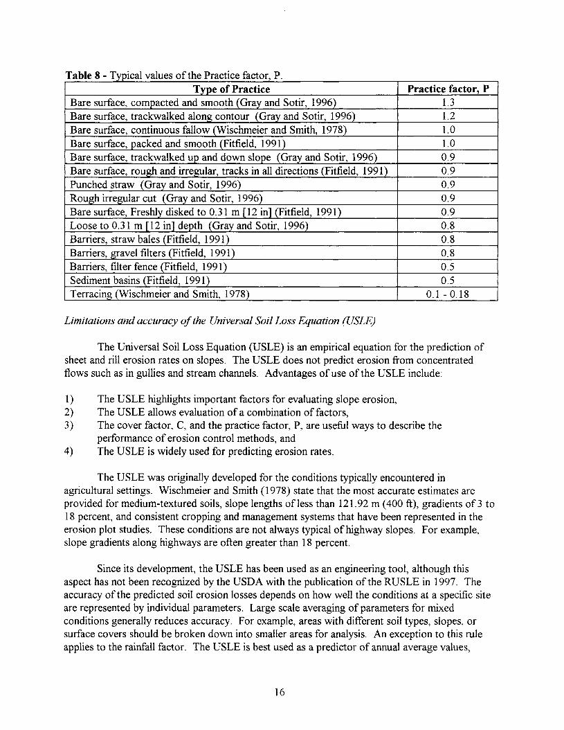
Pfth P t- uT bl 8 T - Ia e - yplca va ues 0 e rac Ice actor,Type of Practice Practice factor, P
Bare surface, compacted and smooth (Gray and Sotir, 1996) 1.3Bare surface, trackwalked along contour (Gray and Sotir, 1996) 1.2Bare surface, continuous fallow (Wischmeier and Smith, 1978) 1.0Bare surface, packed and smooth (Fitfield, 1991) 1.0Bare surface, trackwalked up and down slope (Gray and Sotir, 1996) 0.9Bare surface, rough and irregular, tracks in all directions (Fitfield, 1991) 0.9Punched straw (Gray and Sotir, 1996) 0.9Rough irregular cut (Gray and Sotir, 1996) 0.9Bare surface, Freshly disked to 0.31 m [12 in] (Fitfield, 1991) 0.9Loose to 0.31 m [12 in] depth (Gray and Sotir, 1996) 0.8Barriers, straw bales (Fitfield, 1991) 0.8Barriers, gravel filters (Fitfield, 1991) 0.8Barriers, filter fence (Fitfield, 1991) 0.5Sediment basins (Fitfield, 1991) 0.5Terracing (Wischmeier and Smith, 1978) 0.1-0.18
Limitations and accuracy ofthe Universal Soil Loss Equation (USLE)
The Universal Soil Loss Equation (USLE) is an empirical equation for the prediction ofsheet and rill erosion rates on slopes. The USLE does not predict erosion from concentratedflows such as in gullies and stream channels. Advantages of use of the USLE include:
1) The USLE highlights important factors for evaluating slope erosion,2) The USLE allows evaluation ofa combination offactors,3) The cover factor, C, and the practice factor, P, are useful ways to describe the
performance of erosion control methods, and4) The USLE is widely used for predicting erosion rates.
The USLE was originally developed for the conditions typically encountered inagricultural settings. Wischmeier and Smith (1978) state that the most accurate estimates areprovided for medium-textured soils, slope lengths of less than 121.92 m (400 ft), gradients of3 to18 percent, and consistent cropping and management systems that have been represented in theerosion plot studies. These conditions are not always typical of highway slopes. For example,slope gradients along highways are often greater than 18 percent.
Since its development, the USLE has been used as an engineering tool, although thisaspect has not been recognized by the USDA with the publication of the RUSLE in 1997. Theaccuracy of the predicted soil erosion losses depends on how well the conditions at a specific siteare represented by individual parameters. Large scale averaging of parameters for mixedconditions generally reduces accuracy. For example, areas with different soil types, slopes, orsurface covers should be broken down into smaller areas for analysis. An exception to this ruleapplies to the rainfall factor. The USLE is best used as a predictor of annual average values,
16

rather than for specific storm events. Gray and Sotir (1996) state that considerable judgement isrequired in selecting factor values.
Other Criteria for Evaluating Erosion
The suitability of a particular erosion control product or method is often described interms of a limiting/permissible velocity or a tractive stress. These two criteria have beendeveloped for the evaluation of erosion in channels with concentrated flow. While the flow inditches, gullies, and stream channels is not the subject of this report, a familiarity with thesecriteria is useful when reviewing manufactures' brochures describing erosion control products.
Limiting or permissible velocity criteria
Many guidelines for erosion control products describe the effectiveness of a product interms of a permissible velocity and duration of flow. The velocity of flowing water is a measureof its erosive capacity. The duration of flow is also important. Large storms can develop periodsof flow lasting several days. Over longer periods of flow, lower flow velocities can cause erosivedamage equivalent to higher flow velocities with shorter durations. Accordingly, a flow of longduration may have a much lower permissible velocity than a short duration flow would have.Permissible velocities and durations are determined for specific products and conditions, such aschannel slope, geometry, and soil type. Permissible velocities are often determined based on theresults of laboratory flume testing.
The permissible velocity of flow is compared to the expected velocity to determine thesuitability of a potential channel lining. The permissible velocity for a channel lining should begreater than the expected velocity of flow in the channel. The expected velocity for a given flowchannel is often evaluated based on the peak runoff Iteration using the empirical Manning'sequation links the velocity offlow with the channel geometry (i.e., hydraulic radius), the slope ofthe channel, and the roughness of the channel. Manning's equation is given as:
2 I
V = 1.003R3S2
n
Metric
or
2 I
V = 1.49R3S2
n
English
(6)
where V is the velocity of flow in meters per second (ft/sec), R is the hydraulic radius in meters(feet) [the hydraulic radius is the ratio of cross-sectional area of flow to the length of the wettedperimeter], S is the slope of the channel, and n is Manning's roughness coefficient. Manning'sroughness coefficient is an empirical term used to measure the resistance to flow along the sidesof the flow channel. Hydraulic Engineering Circular No. 15, Design ofRoadside Chan1lels withFlexible Linings, published by the FHWA, describes the use ofManning's equation and providestypical values of the roughness coefficient, n (Chen and Cotton, 1988).
17

Tractive stress criteria
In 1988, the Federal Highway Administration published procedures for evaluating flexiblechannel linings using the criteria of tractive stress (Chen and Cotton, 1988). The principalpractical advantage of the tractive stress criteria is that only a single parameter is used as a failurecriterion, the permissible tractive stress. In addition, use of the tractive stress method is thoughtto provide a more realistic model of erosion within channels than the permissible velocityapproach described above (Chen and Cotton, 1988).
While the tractive stress varies along the sides of a channel, the average tractive stress isgiven by Equation 7 as:
(7)
where 't is the average shear or tractive stress in kPa (pounds per square foot, psf), Yw is the unitweight of water in kN/m3 (pounds per cubic foot, pet), R is the hydraulic radius in meters (feet),and S is the average bed slope. It is worth noting that the tractive stress equation does notcontain a term describing the roughness of the channel.
The tractive stress method is applied in a manner similar to that of permissible velocities.A comparison of the permissible value for a particular lining to the expected value provides abasis for channel lining selection. Chen and Cotton (1988) provide examples for flexible channellining design using the tractive stress method.
Principles Of Soil Erosion Control
Erosion is unavoidable during construction. However, the severity of erosion can bemitigated by the consistent application of the principles of soil erosion control. The origin of theprinciples can be surmised from an evaluation of the terms in the USLE. Principles of erosioncontrol are presented in many sources and their number is not fixed (Goldman et aI., 1986; Carrollet aI., 1992; Virginia, 1992; Wang and Grubbs, 1992; Gray and Sotir, 1996). Goldman et ai.(1986) contains the earliest listing of these principles found, with 10 principles described. TheVirginia Sediment and Erosion Control Handbook (Virginia, 1992) lists and describes sevenprinciples of erosion control. The listing from Goldman et ai. (1986) has been adapted for use inthis section without further attribution.
Fit Development to the Terrain
The natural characteristics of a site should be analyzed during the design of a project.Fitting a project to a site can include aligning roads along contours and locating building pads onthe flatter portions of the site. Roads running straight up and down a hill have a long slope lengthand very high flow velocities, both of which greatly increase the potential for erosion. Buildingon flatter sites reduces the amount of grading required and hence reduces the area stripped ofvegetation.
18

Time Construction Activities to Reduce Soil Exposure
Construction activities should be timed to reduce the exposure of soil to erosion. This canbe accomplished in two ways. First, construction should be staged so that the size of exposedareas is reduced. This includes the prompt installation of erosion control measures in disturbedareas. Second, if possible, construction should be performed during times of the year when theerosion potential is least. Rainfall intensity is a key component affecting the R-factor in theUSLE. In Virginia, 70 to 80 percent of the annual rainfall energy occurs between May andSeptember.
Retain Existing Vegetation
Very little erosion occurs on soil covered with undisturbed vegetation. Reestablishingvegetation can be a difficult and costly process, and even after stabilization, disturbed soils erodeat a rate greater than undisturbed soils. It has been suggested that it takes at least five years forthe rate of erosion at construction sites to approximate the preconstruction rate. Therefore, thearea of construction disturbance should be kept as small as possible.
Use Erosion Control Methods and Practices
Erosion control methods and practices protect the ground surface from erosion andrestrain the movement of eroded soil. The erosion of an unprotected slope under moderaterainfall events, and for even a short period of time, can be much greater than the erosion of aprotected slope. Inspection of the variation in the cover and practice factors for the USLE, asshown in Tables 6, 7, and 8 of this report, clearly shows that the use of erosion control methodsand practices can greatly reduce erosion. Prompt application of these methods and practices cansignificantly reduce erosion on unprotected slopes.
Divert Runoff Away From Denuded Areas
Runoff from areas up gradient should not be allowed to cross construction sites, especiallya site stripped ofvegetation. Diversion ditches or dikes can be used to divert upland runoff awayfrom disturbed areas.
Minimize Length and Steepness of Slopes
Slope length and steepness are important factors influencing the amount of erosion. Longslopes should be broken up; terraces can be used to slow down runoff and allow some sediment tosettle out. Including a ditch on the terrace or slope bench allows for controlled conveyance ofwater to a stable outlet. Cross-slope ditches should have a gentle slope and should be protectedwith an erosion resistant lining if erosion potential exceeds the tolerance of the soil.
19

Keep Runoff Velocities Low
The energy of flowing water increases with the square of velocity. The use of check damsor broad, shallow and flat areas at intervals along a ditch will reduce the velocity of flow andallow settlement of sediments. Runoff velocities in ditches can be kept low by using roughsurfaces such as vegetation or rip-rap. Smooth surfaces, such as concrete, remove runoff quicklyand may cause flooding downstream. Vegetated surfaces or the use of rip-rap more nearlyduplicate channel banks in natural streams and are less likely to contribute to downstreamproblems.
Manage Concentrated Flows
Construction and development can cause runoff that was once diffuse to becomeconcentrated. Concentrated flow has more erosive potential. The increased erosion fromconcentrated flows can be mitigated by designing waterway capacity to withstand peak flows,selecting channel linings to match the expected flows, and using energy dissipaters at criticalpoints in the channel.
Trap Sediment on Site
Eroded soil becomes sediment. Sediment control is the trapping of suspended soilparticles. It is often desirable or required to trap sediments before they leave a construction site.Common sediment barriers include silt fences, sediment ponds, basins, and traps. Erosionprevention is more efficient than attempting to trap soil particles already in suspension.
Inspect and Maintain Erosion Control Measures
Erosion control measures require maintenance to retain their effectiveness. A single stormevent can cause damage that degrades or eliminates the effectiveness of an erosion controlmethod. Examples of this include a breach in a sediment basin, displacement of hay or strawbales, or the loss of anchorage for rolled erosion control products. Inspection and maintenance ofcontrol measures can determine the success or failure of an erosion control program.
Significance of the Principles
Design methods for slope erosion control are not well developed. In the absence of designprocedures, the principles of erosion control are very important. They provide the designer withrules of thumb for making design decisions. As will be shown in subsequent sections, the currentstate of practice within VDOT is based around a design philosophy of diverting and controllingrunoff: managing concentrated flows, and establishing vegetation on slopes. VDOT's currentpractices can be described as principle based design.
20

Methods For Soil Erosion Control
Erosion control consists of reducing the effects of the fundamental erosive mechanisms ofdetachment and transport. The detachment of soil particles can be reduced by protecting orreinforcing the ground surface with a suitable cover. The movement of soil particles can belimited by reducing the tractive forces of flowing water, by curtailing the amount offlow, or bylowering the velocity offlow. The best erosion control methods address both surface protectionfrom raindrop impact and resistance to the transport of soil. However, there are also nicheerosion control methods or products that have been developed to solve specific problems.
Many erosion control measures focus on assisting in the establishment or maintenance ofvegetative cover. These types of measures are known collectively as biotechnical methods oferosion control. However, as erosive forces increase, vegetative cover alone may not besufficient. Armoring of the ground surface may be required to resist erosion. Both biotechnicalmethods and armoring prevent erosion by protecting the ground surface. Their effectiveness isrepresented by the cover factor, C, in the USLE. The practice factor, P, represents thecontribution of improved land management practices in reducing erosion. Descriptions of specificmethods and practices of erosion control are provided below.
Vegetation (Biotechnical Methods)
Any method that uses live vegetation is a biotechnical method of erosion control. Theestablishment ofvegetative cover is traditionally one of the easiest and most efficient methodsused to control erosion, with a dense stand of grass cover being one of the best vegetative covers.Grass resists erosion by increasing interception, restraint, retardation, and infiltration of water.The interception of raindrops prior to their impact on the ground surface reduces the potential forsoil particle detachment. The grass root system provides reinforcement to restrain soil particlesand allows increased moisture infiltration. The presence ofgrass also retards the velocity of flowacross the ground surface, although this effect is more pronounced on flatter slopes (Gray andSotir, 1996). /
Gray and Leiser (1982) and Gray and Sotir (1996) provide a good overview of the uses ofvegetation for erosion control. Russ (1993) provides recommendations for site preparation tofacilitate grass growth. Rodencal (1995) discusses the lifecycle of grasses and the effect oflifecycle on the selection of an erosion control method. Hunt et al. (1998) provide guidelines forvegetation selection and a guide to types ofgrasses. Sotir et al. (1998) provide suggestions forpartnering geosynthetics and vegetation.
The following subsections contain descriptions of specific biotechnical methods that havebeen used to foster and sustain vegetation on slopes for the purpose of controlling erosion. Thesemethods involve the use of manmade and natural materials to protect the ground surface againsterosion until vegetation can be established. The methods include the following:
21

1) Loose mulches, tackifiers, and hydraulic mulches,2) Geosynthetic, rolled erosion control products (RECP) such as nets, meshes, blankets, and
mattings,3) Geocellular containment systems,4) Fiber roving systems, and5) Live staking, live facines and brush-layering.
Each is described below. Sample specifications for the installation of erosion control blankets andmats are available in Berg (1993).
Mulches, Tackifiers, and Hydraulic Mulches
Mulches, a traditional method of erosion control, aid the establishment of vegetation. Theuse of mulches is well accepted. Gray and Sotir (1996) cite three principal benefits ofmulches:1) aiding in the retention of soil moisture by moderating soil temperature and reducingevaporative losses, 2) protecting the ground surface against raindrop impact, and 3) contributingorganic matter to the soil by decomposition of the mulch.
Straw and hay are two common types of mulch that are applied to the slope by hand or bymechanical means. Typical application rates range up to 0.45 kg/m2 (2 tons/acre). Cover factorsin the USLE for application rates from 0.11 to 0.45 kg/m2 (0.5 to 2 tons/acre) are shown inTables 6 and 7. Fiber lengths of 100 to 200 mm (4 to 8 inches) are suggested as most effective.Loose application of mulches is often used on relatively flat slopes. However, loose mulches aresusceptible to blowing and washout. On steeper slopes, some means of anchoring the mulch tothe ground surface must be used. Table 9 provides a summary of the advantages anddisadvantages of mulches in erosion control.
Table 9 - Advantages and disadvantages of mulches (after CE News, 1998).
Advantages Disadvantages
• Lowest cost erosion control method • Very temporary (less than 1 year)
• Well accepted • Should not be used under severe conditions
• High installation rate, can be placed rapidly • Dusty
• Moderate sediment yield • May require tackifier
• Promotes vegetative density
Tackifiers consisting of asphaltic emulsions, acrylic polymers, or vegetable gums are oftenused to hold mulches in place. Miller et al. (1996) describe a testing program for two tackifiersand note that no standard test method is available for evaluating the effectiveness of tackifiers.The tests conducted by Miller et al. (1996) were performed on slopes at a 25 degree inclination,nearly 2H: 1V. Using a tackfier provides erosion protection for only a very short time, duringwhich vegetation must become firmly started. The tackifiers tested by Miller et al. (1996)degraded and broke down over an 8 week period after placement.
22
Lentz and Sojka (1996) describe a method similar to the use of a tackifier. They used afloculant, polyacrylamide (PAM), in irrigation water to reduce the effect of erosion. They foundthe use ofPAM to be most effective on slopes with an inclination of less than 7 percent.
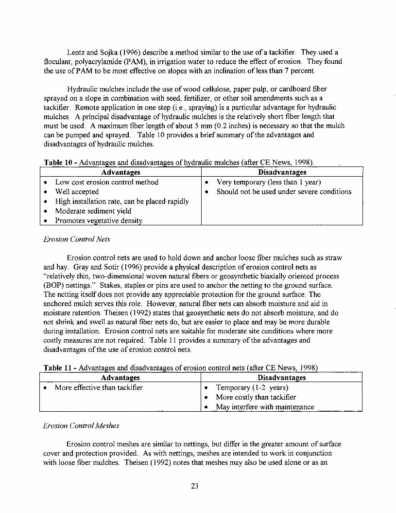
Hydraulic mulches include the use of wood cellulose, paper pulp, or cardboard fibersprayed on a slope in combination with seed, fertilizer, or other soil amendments such as atackifier. Remote application in one step (i.e., spraying) is a particular advantage for hydraulicmulches. A principal disadvantage of hydraulic mulches is the relatively short fiber length thatmust be used. A maximum fiber length of about 5 mm (0.2 inches) is necessary so that the mulchcan be pumped and sprayed. Table 10 provides a brief summary of the advantages anddisadvantages of hydraulic mulches.
Table 10 - Advantages and disadvantages of hydraulic mulches (after CE News, 1998).Advantages Disadvantages
• Low cost erosion control method • Very temporary (less than 1 year)
• Well accepted • Should not be used under severe conditions
• High installation rate, can be placed rapidly
• Moderate sediment yield
• Promotes vegetative density
Erosion Control Nets
Erosion control nets are used to hold down and anchor loose fiber mulches such as strawand hay. Gray and Sotir (1996) provide a physical description of erosion control nets as"relatively thin, two-dimensional woven natural fibers or geosynthetic biaxially oriented process(BOP) nettings." Stakes, staples or pins are used to anchor the netting to the ground surface.The netting itself does not provide any appreciable protection for the ground surface. Theanchored mulch serves this role. However, natural fiber nets can absorb moisture and aid inmoisture retention. Theisen (1992) states that geosynthetic nets do not absorb moisture, and donot shrink and swell as natural fiber nets do, but are easier to place and may be more durableduring installation. Erosion control nets are suitable for moderate site conditions where morecostly measures are not required. Table 11 provides a summary of the advantages anddisadvantages of the use of erosion control nets.
Table 11 - Advantages and disadvantages of erosion control nets (after CE News, 1998).Advantages Disadvantages
• More effective than tackifier • Temporary (1-2 years)
• More costly than tackifier
• May interfere with maintenance
Erosion Control Meshes
Erosion control meshes are similar to nettings, but differ in the greater amount of surfacecover and protection provided. As with nettings, meshes are intended to work in conjunctionwith loose fiber mulches. Theisen (1992) notes that meshes may also be used alone or as an
23

underlayer for sod reinforcement. Erosion control meshes are woven using either natural orgeosynthetic yarns. Natural fibers include either jute or coir (coconut fiber), while polypropylenegeotextiles are used in common geosynthetic meshes. Gray and Sotir (1996) describe coir meshesas being particularly durable (a useful life of 5 to 10 years) with high tensile strength (1790 kg/mto 2684 kg/m [100 to 150 pounds per inch]) and high moisture retention. Jute meshes are notedfor their moisture retention, with a water absorption capacity of 450 percent of the dry fabricweight (Gray and Sotir, 1996). An advantage of natural fibers is that they add organic matter tothe soil when they degrade. Geosynthetic meshes have high tensile strength to unit weight ratios,but do not significantly retain moisture. Geosynthetic meshes are generally biodegradable. Table12 summarizes the advantages and disadvantages of erosion control meshes.
Table 12 - Advantages and disadvantages of erosion control meshes (after CE News, 1998).Advantages Disadvanta2es
• Low to moderate cost • Temporary (1-2 years)
• Moderate sediment yield • Low flows only
• Good vegetative density • Not complete ground cover
• Good moisture absorption
Erosion Control Blankets
Erosion control blankets (ECBs) combine the protective function of mulches with thestructure of nettings and meshes. Erosion control blankets are constructed from a blanket ofsynthetic or natural fibers constrained by woven, glued, or bound geosynthetic biaxially orientedprocess (BOP) netting or woven natural netting. Fibers consist of some combination of straw,wood, excelsior (a processed wood fiber), coconut, or polypropylene. A wide variety ofECBsare available. Their properties, such as strength and durability, are diverse. Erosion controlblankets should be installed in very close contact with the ground surface. Erosion rills can formbeneath improperly installed ECBs. As with nettings and meshes, ECBs are held in place withstakes, staples, or pins. VDOT's list of approved products includes erosion control blankets asEC-2 type products. Appendix B contains this listing.
Erosion control blankets are for use under more difficult site conditions than are advisablefor nettings or meshes. According to Gray and Sotir (1996), ECBs can be applied on slopes withinclinations up to 1H: 1V when flow velocities are under 2.74 meters per second (9 feet persecond) for flows with a duration of less than 2 hours. They also can be used on low-impactshorelines. Koerner and Carson (1998) evaluated the field performance ofECBs, and theirrecommendations for usage are more conservative. While they did not test resistance to flow orshoreline application, Koerner and Carson (1998) recommend the use ofECBs for slopes up to2H: 1V. Additional descriptions ofECB performance can be found in Armstrong and Wall(1991), Fitfield (1992), and Northcutt (1993). Because erosion control blankets degrade withtime, their use is limited to areas where permanent, natural vegetation will eventually providelong-term erosion protection. Table 13 is a summary of the advantages and disadvantages for theuse ofECBs for erosion control.
24

Table 13 - Advantages and disadvantages of erosion control blankets (after CE News, 1998).Advantages Disadvantages
• Low cost • Temporary (1-2 years)
• Easy to install • Low to moderate flows
• Very good vegetative density • May interfere with maintenance
• Very low sediment yield
• Good moisture absorption
Erosion Control Mats
Unlike mulches, nettings, meshes, and ECBs, erosion control mats provide long-termerosion protection. Erosion control mats are constructed from geosynthetics stabilized againstdegradation under ultraviolet (UV) light. The matting consists of a matrix of interconnectedfibers, which become fully penetrated by plant roots and soil. Erosion control mats providereinforcement to restrain the movement of soil and vegetation. Erosion control mats should beinstalled in very close contact with the ground surface. As with nettings, meshes, and blankets,erosion control mats are held in place with stakes, staples, or pins.
There are two classes of erosion control mats available: 1) turf reinforcement mats(TRMs), and 2) erosion control revegetation mats (ECRMs). Figure 5 shows a cross-sectionillustrating the near surface reinforcement provided by a TRM. Gray and Sotir (1996) higWightthe differences between TRMs and ECRMs. Turf reinforcement mats have a thicker cross-sectionthan ECRMs. Perhaps the most significant differences between TRMs and ECRMs are in theirmethods of installation. The ground surface is not seeded prior to placement of a TRM. The matis covered with soil and seeds after installation. In contrast, the ground surface is seeded prior toplacement of an ECRM. No soil or seeds are used after installation. This order of application canbe a disadvantage, because vegetation is established more slowly as the ECRM is gradually filledwith sediments. However, erosion control revegetation mats are denser and provide better shortterm erosion protection. Table 14 higWights the advantages and disadvantages of erosion controlmats.
Erosion control mats should be used for difficult site conditions. Koerner and Carson(1998) recommend the use of turf reinforcement mats for slopes steeper than 2H: 1V. The use oferosion control mats as soft-armor is described by Carroll and Theisen (1990), Carroll et al.(1991), Cazzuffi et al. (1991), and Theisen and Carroll (1990). VDOT's list of approvedproducts includes erosion control mats as EC-3 type products. Appendix B contains this listing.
25

dT bI 14 Ada e - vantages an disadvantages of erosion control mats (after CE News, 1998).Erosion Control and Reve2etation Mats
Advanta2es Disadvanta2es
• Long term protection • Use for moderate water flows only
• Low sediment yields • Moderate costs
• High vegetative density • Gradual vegetative growthTurf Reinforcement Mats
Advantages Disadvanta2es
• Long term protection • Moderate costs
• Use for difficult slope conditions • Low to moderate sediment yields
• Protects against moderate to high water flows
• Moderate to high vegetative density
Topsoil _________
Turf ~Reinforcement ----.l.................-:'I~i
Mat
OriginalGround- ~Surface
~! '
Figure 5 - Cross-section illustrating the interpenetration ofroots and soil into the matrixof a turf reinforcement mat (Biotechnical and Soil Bioengineering Slope Stabilization - APractical Guidefor Erosion Control, D. H. Gray and R. B. Sotir, copyright © 1996, JohnWiley and Sons. Reprinted by permission of John Wiley and Sons, Inc.)
26

Width: 0.13 mcta-s (5 inches)
Geocellular Containment Systems
Geocellular containment systems (GCSs) consist ofa web of polymeric strips.Polyethylene or polyester strips are typically used. When expanded, GCSs provide an areal,honeycomb pattern of individual cells. Figure 6 illustrates the expansion ofa GCS. The GCS celldepth is generally up to 200 nun (8 in). Once expanded and placed on a slope, the cells are filledwith soil, gravel, or concrete. If filled with soil and seeded, the upper surface is often coveredwith an erosion control net or mesh to aid vegetative growth. If used as a channel lining, GCSsfilled with stone or concrete can offer significant surface protection.
Cancelli et al. (1990) suggest using zoned protection for slopes with the lower portion ofthe slope protected with a GCS and the upper portions of the slope protected with an erosioncontrol mat or other appropriate method. Wu and Austin (1992) provide an excellent discussionof design methods and parameters values for GCSs. Table 15 is a listing of the suggested designvalues for GCSs used as channel linings provided by Wu and Austin (1992). Table 16 lists theadvantages and disadvantages of the use of a GCS for erosion control.
EXPANDEDWidth: 0.20 meters (8 inches)
COMPRESSED
~3.35 meters(11 feet) --J
Figure 6 - Schematic illustration of geocellular containment system (Biotechnical andSoil Bioengineering Slope Stabilization - A Practical Guide for Erosion Control, D. H.Gray and R. B. Sotir, copyright © 1996, John Wiley and Sons. Reprinted by permissionof John Wiley and Sons, Inc.)
27

Table 15 - Geocellular design values for channel linings (after Three-dimensionalPolyethlene Geocells for Erosion Control and Channel Linings. Geotextiles andGeomembranes, K. J. Wu and D. D. Austin, copyright © 1992, International GeotextileSociety, Vol. 11, pp. 611-620. Reprinted with permission from Elsevier Science.)
Geocell diameter Roughness Limiting velocityIntill material mm (inches) coefficient, n m/s (fps)
Unvegetated topsoil 75 - 125 (3-5) 0.017 0.91 (3)Vegetated topsoil 75 - 200 (3-8) 0.024 1.52(5)
Coarse sand 100 - 200 (4-8) 0.020 1.83 (6)Gravel 150 - 300 (6-12) 0.022 2.44 (8)
Concrete 150 - 300 (6-12) 0.013 4.57 (15)
Table 16 - Advantages and disadvantages ofgeocellular containment systems(after CE News, 1998).
Advantages Disadvantages
• Provides long term protection • Moderate costs
• Protects against moderate to high water flows • Delayed vegetative establishment
• Encourages infiltration • Special installation requirements
• Low to moderate sediment yields • Low vegetative density
• Can accommodate various fill materials andplantings
Fiber Rovil1g Systems
Fiber roving systems are significantly different from the erosion control methods describedpreviously. Fiber roving systems are installed by applying a continuous strand of either fiberglassor polypropylene fiber to a pre-seeded ground surface (Theisen, 1992). The roving is thenanchored in place using a tackifier. Fiber roving systems are often described as providing onlytemporary erosion protection. However, UV stabilizers can be added to polypropylene roving toextend its useful life. The method of application ensures that the applied material is in closecontact with the ground surface. In addition, the width and thickness of the applied roving can beeasily controlled and tailored to provide the desired erosion protection. A summary of theadvantages and disadvantages of fiber roving for erosion protection is in Table 17.
Table 17 - Advanta es and disadvanta es of fiber rovin s stems after CE News, 1998 .Advanta es Disadvanta es
• Low to moderate costs • Temporary (1-2 years)• High subgrade conformance • Protects against low to moderate water flows• Very low sediment yield • Special equipment required for installation• Ve ood ve etative densit
28

Live Planting Methods
Live planting methods such as live staking, live facines, and brush-layering are oftenthought of as quintessential biotechnical methods. However, as mentioned above, biotechnicalmethods are more broadly defined as the use of vegetation, often in conjunction with a structuralelement, to provide surface protection and erosion control. The structural element may consist oferosion control nets, meshes, blankets, or mats, for example.
Live planting methods install live vegetation into a prepared ground surface. Live stakingis the insertion of live, rootable vegetation directly into the slope surface. In contrast, the livefacine method uses tied bundles of plant material placed in shallow trenches on the surface of theslope. An advantage for the use of live facines is that the slope length used in the USLE can besignificantly reduced (USD~ 1997). Brush-layering is similar to the use of live facines. Withbrush-layering, live, cut branches are placed in an overlapping pattern and partially covered withsoil. The goal of all three techniques is rapid plant growth and improved aesthetic appeal. Theselection of suitable vegetation for the particular application is a critical component for the use oflive planting methods. To aid in plant selection, consultation with a landscape architect may beadvisable where experience with specific species or conditions are not available. An advantage oflive plantings is the rapid establishment of vegetation. However, the installation of live plantingsis often labor intensive.
Armoring
The use of vegetation, as described above, is a common and effective method forproviding erosion protection. However, for more challenging site conditions, slope armoring canbe used. Armoring consists of protecting the ground surface with particles too large to bedisplaced by erosive forces or by providing a ground cover strong enough to resist displacementby flowing water. Armoring provides a great deal of erosion protection; however, the cost isrelatively high. Rip-rap and gabions are traditional methods for protecting the ground surfacefrom erosion under severe conditions. More recently, fabric formed revetments and articulatedconcrete blocks have been added to the category of erosion control methods that can be used toarmor a slope. Each method is described in the following subsections.
Rip-rap
The most common method of armoring is the use of rip-rap. Rip-rap is the placement oflarge stones (i.e., gravel, cobbles, or boulders) on the ground surface to provide long-term erosionprotection. The effectiveness of rip-rap depends on the size of the stones to resist detachment andtransport by water. Stone used for rip-rap should be hard, dense, angular in shape, and shouldresist weathering and water action. Duffy and Hatzell (1991) found that particles at least 38 mm(1.5 in) in diameter were required to prevent erosion on a 2H: 1V slope.
A filter layer is recommended between the ground surface and the rip-rap to prevent soilerosion through the voids between large stones. Holtz et al. (1997) provide a description,criteria, and sample specifications for the use of geotextiles as the filter base for rip-rap.
29

Disadvantages for the use of rip-rap are labor intensive installation, high costs, andrelatively poor visual aesthetics. Gray and Sotir (1996) suggest the use of live cuttings with riprap to increase its visual appeal.
Gabions
Gabions originally had a military use~ baskets of soil were used to provide protection forthe attackers during a siege. Today, gabions are baskets filled with stones used as a stabilizingmeasure for slopes or to provide long-term erosion protection. The baskets hold the stones inplace and allow the use of relatively smaller individual stones than would be used for rip-rap. Thebaskets are often constructed using wire or using geogrids with a high tensile strength andresistance to abrasion. Wire baskets in a corrosive environment may use a PVC coating ongalvanized wire. An advantage of gabions is that they can be stacked in a variety of ways to actas structural building blocks. The advantages and disadvantages of using gabions for erosioncontrol are very similar to those for rip-rap and are listed in Table 18.
Table 18 - Advanta es and disadvanta es ofAdvanta es
• Provides long term (indefinite) protection• Use for severe conditions• Encourages infiltration• Low sediment ields
Fabric-Formed Revetments
after CE News, 1998 .Disadvanta es
• Moderate costs• Delayed vegetative establishment• Labor intensive installation• Low ve etative densit
Fabric-formed revetment systems (FFRs) are formed from two layers of geotextiles filledby pumpable concrete or cement grout. The resulting mat conforms closely to the subgrade.Articulating block mats may use two layers of woven geotextile joined in a quilt-like pattern, orhigh strength reinforcing strands can be used to connect segments and allow articulation of theresulting mat. Weep tubes can be used between segments to relieve uplift pressures. As withother armoring systems, the use of a filter layer beneath the FFR is recommended. Table 19summarizes the advantages and disadvantages ofFFRs.
Table 19 - Advantages and disadvantages offabric-formed revetments (after CE News, ]998).Advantages Disadvantages
• Provides long term (indefinite) protection • Moderate costs
• Use for severe conditions • No vegetation
• Very low sediment yields • Does not encourage infiltration
• Smooth durable lining • Special equipment required for installation
• Accurate underwater placement
30

Articulated Blocks
Articulated block systems are formed from prefabricated concrete blocks placed as matsor as individually interlocked blocks. The blocks are laid on a smooth prepared subgrade that hasbeen covered with a geotextile filter fabric. To provide additional strength, cables may be used toconnect individual blocks. Openings between blocks allow for equalization of uplift pressure andthe introduction ofvegetation. Articulated block systems provide a relatively smooth surface thatcan be aesthetically pleasing. Table 20 provides a summary of the advantages and disadvantagesof articulating concrete blocks as an erosion control system.
Table 20 - Advantages and disadvantages of articulating concrete blocks (after CE News, 1998).Advanta2es Disadvanta2es
• Provides long term (indefinite) protection • High cost
• Use for severe conditions • Delayed vegetative establishment
• Encourages infiltration • Special installation requirements
• Very low sediment yields • Low vegetative density
• Can accommodate vegetation
• Can be prefabricated into mats
Improved Practices
Improved practices affect erosion by modifying the flow pattern of runoff: by reducing therate of runoff: and by trapping sediment to reduce the amount of soilleav~ngthe site. Theeffectiveness of improved practices in trapping sediments is reflected in the practice factor, P, inthe universal soil loss equation. As implied by the use of separate factors in the USLE, improvedpractices may be combined with other erosion control methods that reduce the amount of erosion,either through vegetation or by armoring the slope. The use of silt fences, hay bales, terracing ofthe site, check dams, and sediment basins are all examples of improved erosion control practices.These are described in the following subsections.
Silt Fences, Hay Bales, and Brush Layers
Silt fences, hay bales, and brush layers are temporary barriers used to intercept andrestrain the movement of sediments. These measures are often used as a perimeter control arounda construction site. The use of these controls does not imply that other measures to preventerosion are not required. Silt fences, hay bales, and brush layers can be though of as the last lineof defense.
Silt fences typically consist ofgeotextile filter fabric stretched between driven stakes. Ananchor trench should be used at the base of the fence to prevent flow beneath the barrier.Properly installed silt fences can have sediment trapping efficiencies as high as 97 percent,although poor installation and maintenance can greatly reduce their effectiveness (Virginia, 1992).Many installed silt fences are too short, less than 0.41 m (16 in) high; silt fences should be 0.61 to0.86 m (24 -34 in) high to prevent breaching and should be properly supported. Good Sllpport
31
for silt fences includes the use of stout staking with stakes at least 1.52 m (5 ft) long or the use ofa wire supported fence. A sample specification for silt fences is provided in Holtz et al. (1998).
Straw bale barriers are widely used as an erosion control practice because of their low costand ease of installation. Straw bale barriers, however, may not be the most effective form oftemporary barrier because careful installation is required for effective use. Poor installationoccurs, for example, where flow depths and velocities are too great or where a poor bale-groundinterface allows flow to pass under the barrier. The maintenance ofbale barriers is critical; theVirginia Erosion and Sediment Control Handbook (Virginia, 1992) notes that trapping efficienciesmay drop from 57 percent to 16 percent in a single month due to lack of maintenance.
Brush layers use the organic litter from site clearing operations, placed in windrows, as atemporary sediment barrier. The use of tree stumps and other large diameter (i.e., over 150 mm[6 in] in diameter) objects cause large voids in the barrier, reducing its effectiveness. Geotextilescan be used to cover brush barriers to increase their effectiveness in trapping sediment. Ananchor trench and tie downs should be used with the geotextile to hold it in place. Brush layersare not used as commonly as are silt fences and straw bales, but they offer the advantage of usinga waste material constructively.
The Virginia Erosion and Sediment Control Handbook (Virginia, 1992) recommends theuse of these temporary barriers where the watershed above the barrier is less than 1011.7 m2(1/4of an acre) per 30.48 meters (100 ft) of barrier length, which means the maximum slope lengthabove the barrier is 30.48 meters (100 feet), and the maximum slope inclination above the barrieris 2H:1V.
Terracing
Terraces or benches are one of the most effective long-term practices used to controlerosion on slopes. Terraces have two principal benefits; they act to reduce sheet and rill erosionby reducing the slope length, and trap eroded sediment on the slope.
Figure 4 shows the reduced horizontal slope length used with terraces. The effect ofreduced length is represented in the L-factor in the USLE as shown in Equation 2 (Wischmeierand Smith, 1978).
The low velocity flows along terraces have low erosive potential, and they allow erodedsoil to settle out. The use of low cross slope grades increases trapping efficiency. The practicefactor, P, assigned for terracing represents this secondary effect of reduced erosion and thetrapping of sediment (Wischmeier and Smith, 1978). The value of the practice factor is also basedon the length of the slope using one of three cases:
32
1) For smaller slopes, i.e., slopes with a length less than 33.53 meters (110 feet), use the practicefactor from Table 8. Terraces are most effective when they reduce the horizontal slope lengthto less than 33.53 meters [110 feet] (USDA, 1997).
2) For large slopes, slopes with a length greater than 94.44 meters (300 feet), use a P-value of1.0. No benefit is provided for long distances between terraces.
3) For intermediate slopes, i.e., slopes with a length between 33.53 and 94.44 meters (110 to 300feet), interpolate the P-value based on the slope length. The benefits of terracing decreasegradually until no benefit is assigned using the USLE practice factor, P, for spacings greaterthan 94.44 meters (300 ft).
The principal disadvantage for the use of terraces is that maintenance is required. Theeroded soil trapped over time must be removed to maintain the efficiency of the terrace.
Sediment Traps and Rock Check Dams
Sediment traps and rock check dams are relatively small structures used to reduce flowvelocities so that sediments can settle out. The sizing of sediment traps and rock check dams isoften based on judgement and experience; relatively little engineering design effort is applied tothese structures.
A sediment trap is a temporary ponding area used for drainage areas less than 12, 140 m2
[3 acres] (Virginia, 1992). The efficiency of sediment traps is on the order of 40 to 60 percent.
Rock check dams are installed along ditches or other flow channels to reduce the velocityof flow. Check dams should be less than 0.91 meters (3 ft) high and should be used for drainageareas less than 40,470 m2 [10 acres] (Virginia, 1992). To be most effective, check dams shouldbe spaced so the crest of a lower check dam is at the same elevation as the toe of an upper checkdam.
Sediment Basins and Ponds
Sediment basins and ponds are larger structures used to control the movement ofsediments. As opposed to check dams and sediment traps, sediment basins and ponds can requiresignificant engineering design effort. The trapping efficiencies of well designed sediment pondscan be quite high. Sediment basins and ponds offer the last opportunity to capture eroded soilbefore it leaves a site.
Summary Of VDOT Interviews
As part of this project, interviews with VDOT personnel were conducted. The pllrpose ofthe interviews was to gain an understanding of the ways that VDOT designs, constructs, andmaintains erosion control measures for slopes. Materials, drainage, and environmental personnelwere interviewed in each of the nine VDOT districts between March 26 and May 3, 1999. Theinterviews were conducted by Mr. Jessee A. Scarborough of Virginia Tech.
33

Prior to these interviews, a series of questions were developed during February and earlyMarch. The questions were assembled in the form of a Requestfor Information about SlopeErosion Control. Appendix A contains the questionnaire. The survey included 32 questionsdealing with the perceived importance of slope erosion control, factors affecting erosion, factorsgoverning the selection of an erosion control method, construction inspection and maintenance,post-construction inspection and maintenance, and the conditions under which erosion controlmeasures fail. Before the interviews, the questions were sent to each respondent to allowfamiliarity and preparation for the meetings. The questionnaire provided the agenda at meetingsin each of the nine districts.
On the basis of these meetings, it is clear that there are no specific, formal procedurescurrently in use within VDOT for dealing with slope erosion. However, slope erosion controlwas generally perceived as a very important issue, and a general design philosophy was found..Currently, designers generally try to limit erosion by 1) diverting runoff: 2) controllingconcentrated flows and 3) establishing vegetation on slopes as quickly as possible.
The survey revealed that vegetation was used for long-term erosion control on virtually allprojects. Rip-rap was used on about 30 percent of the projects, generally for repairs.Geosynthetic erosion control products were used on about 20 percent of projects. The use ofother methods for long-term erosion control was sporadic.
Silt fences were found to be the most frequent practice used for temporary sedimentcontrol. The use of hay bales and brush layers was much lower, at average use rates of about 10percent and 20 percent, respectively.
Construction inspection of erosion control was perceived as adequate in five of the ninedistricts. A lack of personnel to perform inspections was generally cited as the reason forinadequate inspection. Modification of the erosion control measures designed and specified in theplans was generally not required during construction. Fitting the design to actual conditions wasthe reason most often given for the relatively rare changes that were made. However, mostdistricts stated that the timing of installation for erosion control measures usually exceeded thatallowed by current regulation, specification, or policy.
As with construction inspection, similar perceptions of post-construction inspection andmaintenance were found in the survey. Personnel in five of the nine districts believed postconstruction efforts to be adequate. Visibility of an area to the public and to drive-by inspectionswas often given as a controlling factor for maintenance performed.
The following subsections describe information obtained from VDOT during the survey.This information includes factors contributing to erosion; selection of erosion control methods;and construction, maintenance, and performance of slope erosion controls. Finally, the districtresponses to a request for other comments about slope erosion are presented.
34

Factors Contributing to Erosion
One purpose of the survey was to determine what factors were perceived by VDOTpersonnel as contributing to slope erosion. Inquiry was made into the effect of rainfall durationand intensity, soil type, slope length and inclination, and differences between cut and fill slopes onslope erosion.
Rainfall duration and intensity were not factors considered by VDOT personnel in relationto slope erosion. Six out of nine districts cited the use of rainfall duration and intensity in sizingditches and curbing, but not for evaluating slope erosion.
Soil type was generally perceived as a factor contributing to slope erosion by VDOTpersonnel. Problem soils were often identified by the respondents. Table 21 is a summary of thecomments made about soil type and its influence on the erodibility of slopes. Soils were classifiedas problematic by either being highly erodible or by inhibiting the establishment ofvegetation.The two most frequently mentioned cases of problematic soil conditions were: 1) micaeous soilswere identified as being highly erodible, and 2) residuals soils with a low pH (acidic) were citedas being difficult for establishing vegetation.
- d-nflT bl 21 Pa e - ercelve I uence 0 SOl :ype or con I Ion on s ope erosionFrequency
Soil condition (cited in x of 9 districts) CommentMicaeous silts 6 High erodibilityLow pH residual soils 4 Establishing
vegetation difficultSandy soils more erodible than 2 Relative erodibilityclayey soilsPlacement of topsoil 2 Promotes
vegetative growthClays with low strength 1 Poor surficial
stabilitySoils with low plasticity 1 High erodibilitySilty clays and sandy, silty clays 1 High erodibilityRock fragments in soil 1 Reduces erodibility
Flattening the slope was cited as a potential solution for sites with highly erodible soils.However, increasing the amount of erosion protection on the surface of the slope was notmentioned in the context of designing slopes to reduce erosion. Increasing erosion protection wascited as a remedial measure after an erosion problem was discovered.
The use of topsoil was cited as a potential solution for sites where it was difficult to getvegetation growing. One district reported a need for VDOT guidelines concerning when topsoilshould be placed on slopes.
35
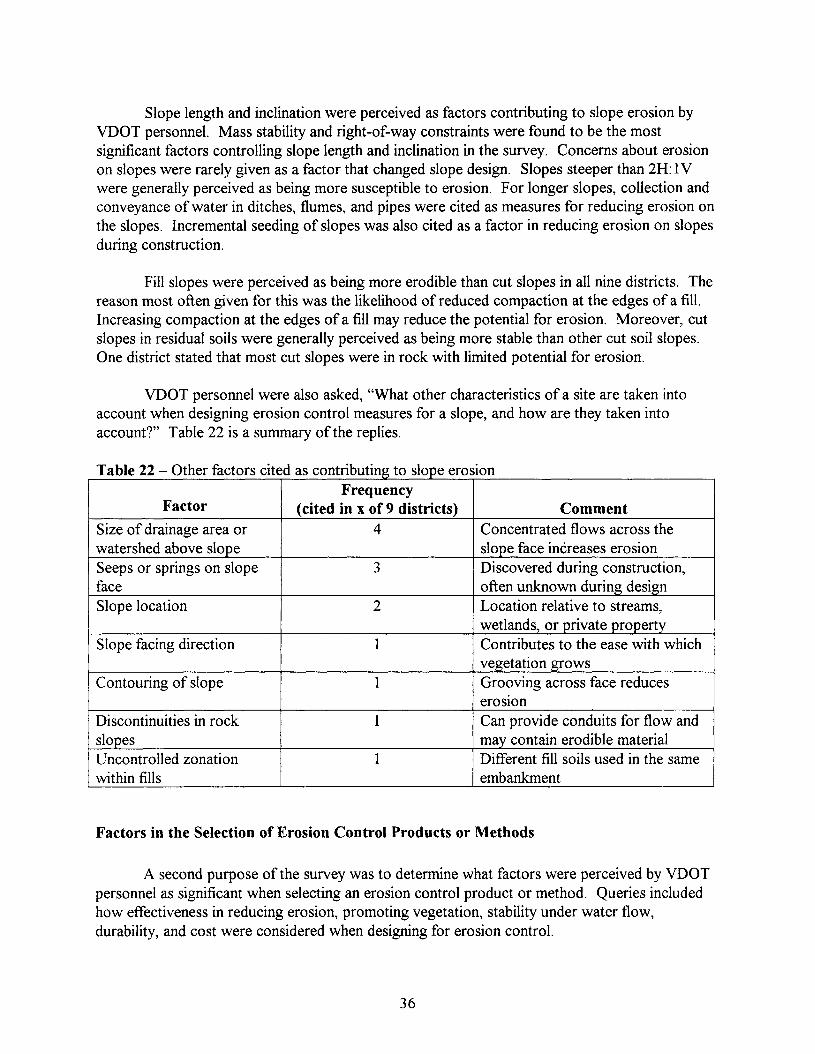
Slope length and inclination were perceived as factors contributing to slope erosion byVDOT personnel. Mass stability and right-of-way constraints were found to be the mostsignificant factors controlling slope length and inclination in the survey. Concerns about erosionon slopes were rarely given as a factor that changed slope design. Slopes steeper than 2H: 1Vwere generally perceived as being more susceptible to erosion. For longer slopes, collection andconveyance of water in ditches, flumes, and pipes were cited as measures for reducing erosion onthe slopes. Incremental seeding of slopes was also cited as a factor in reducing erosion on slopesduring construction.
Fill slopes were perceived as being more erodible than cut slopes in all nine districts. Thereason most often given for this was the likelihood of reduced compaction at the edges of a fill.Increasing compaction at the edges of a fill may reduce the potential for erosion. Moreover, cutslopes in residual soils were generally perceived as being more stable than other cut soil slopes.One district stated that most cut slopes were in rock with limited potential for erosion.
VDOT personnel were also asked, "What other characteristics of a site are taken intoaccount when designing erosion control measures for a slope, and how are they taken intoaccount?" Table 22 is a summary of the replies.
T bl 22 0 h ta e - t er actors CI e as contn utlng to s ope erosIonFrequency
Factor (cited in x of 9 districts) CommentSize of drainage area or 4 Concentrated flows across thewatershed above slope slope face increases erosionSeeps or springs on slope 3 Discovered during construction,face often unknown during designSlope location 2 Location relative to streams,
wetlands, or private propertySlope facing direction 1 Contributes to the ease with which
vegetation growsContouring of slope 1 Grooving across face reduces
erosionDiscontinuities in rock 1 Can provide conduits for flow andslopes may contain erodible materialUncontrolled zonation 1 Different fill soils used in the samewithin fills embankment
Factors in the Selection of Erosion Control Products or Methods
A second purpose of the survey was to determine what factors were perceived by VDOTpersonnel as significant when selecting an erosion control product or method. Queries includedhow effectiveness in reducing erosion, promoting vegetation, stability under water flow,durability, and cost were considered when designing for erosion control.
36

Based on the survey, the effectiveness of an erosion control product or method was onlyknown based on prior experience. Experience with methods proven effective in the past wasgenerally considered to be the most important factor in selecting products or methods for futureuse. The importance of experience was cited in six of the nine districts. Only one district statedthat the current procedures for selecting erosion protection were adequate.
Seven out of nine districts indicated that vegetation was the best erosion control measure.The prevailing view seemed to be that most erosion control measures were temporary untilvegetation could be established. Permanent measures, such as geosynthetic mattings and rip-rap,were generally used as a remedial measure for erosion problems. A notable exception to thispractice was the use of rip-rap under bridges. Rip-rap is often used for this application because itis difficult to establish vegetation under bridges.
VDOT personnel stated that the stability of erosion control products or methods underwater flow was not an important factor for design against erosion on slopes. However, thecontrol of water flow from watersheds above slopes was cited as a very important factor incontrolling slope erosion. Flumes and pipes were used to convey storm water down a slope.Stability under water flow was identified as a significant criteria for erosion protection withinflumes and ditches.
The durability of erosion control products or methods was generally not considered asignificant factor for design. Three districts indicated that erosion control measures must last longenough for vegetation to be established, but that longer lasting measures may provide amaintenance problem by interfering with mowing. There was recognition·within the districts thatthere was a difference in durability between products on VDOT's approved lists. Erosion controlblankets (i.e., EC-2 type products) were perceived as less durable than erosion control matting(Le., EC-3 type products).
The costs for erosion control were not considered in a systematic fashion within theVDOT districts. Engineering concerns, design factors, and compliance with applicableregulations were all of more concern than costs. However, there was a perception that doing itright the first time is less expensive than dealing with continuing maintenance problems. Costs forerosion control were suggested to be of more concern to the residencies than to the districts.VDOT residencies are administrative divisions within a district with jurisdiction for maintenanceand small construction efforts.
VDOT personnel were also asked, "What other factors are taken into account whenselecting slope erosion control products or methods, and how are they taken into account?"Table 23 is a summary of the responses.
37

th ddT bl 23 0 h £a e - t er actors Important In se ectlng erosion contro pro ucts or me o sFrequency
Factor (cited in x of 9 districts) CommentEnvironmental or water 4 Sites near streams or wetlands mayquality issues require stronger controlsSize of drainage area or 3 Concentrated flows across thewatershed above slope slope face increases erosionAesthetics 2 How the slope face looks to the
driving publicConstructability 2 Site access can be a problemContouring 1 Roughening the face of the slope
aids vegetative establishmentFreeze thaw 1 Affects surficial stabilitySeason/time ofyear 1 Time of year affects vegetative
growthReducing time of exposure 1 Bare ground is much more
susceptible to erosionVDOT guidelines 1 See Appendix D
The survey respondents were asked what other information and design aids would behelpful in designing slope erosion control measures. A wide variety of responses were received.Table 24 is a listing by district.
Construction, Maintenance, and Performance of Slope Erosion Controls
Another major purpose of the survey was to inquire how measures to prevent slopeerosion have performed in the field. VDOT personnel were asked about construction,maintenance, and performance of erosion control measures on slopes. Inspection andmaintenance during and after construction were examined, as were the reasons that slope erosioncontrols failed.
Construction inspection of erosion control was perceived as adequate in five of the ninedistricts. Conversely, construction inspection was not thought to be adequate in the other fourdistricts. Most of the erosion controls specified in the plans were built without modification. Inthe cases where changes were made, field engineering to fit the design to the actual conditionswas a primary reason for changes.
The time required for installation of slope erosion control measures generally exceededthat required by regulation, specification, or policy. Perimeter controls, such as silt fencing, weredescribed as being installed prior to the start of work in most cases. However, the timing ofsubsequent seeding during construction was found to vary widely. This variation was reported byone district as being from hours to months after the slope was cut or placed.
38

Table 24 - Design aids or other needed help
DistrictWhat information and/or design aids would be most helpful for use indesigning slope erosion control measures?
Bristol None requiredCulpepper 1) We would like to have a computer program, "Windows" based, to
consider sheet flow on slopes. The program should allow for incrementalconsideration of the slope. 2) A responsible party for erosion control inVDOT should be designated.
Fredericksburg 1) Flexibility in design, the ability to tailor the design to the project.2) We need training for the installation and use of geosynthetics and othersimilar products.
Lynchburg Simple charts that provide guidance for selecting methods and provideguidance about where specific methods should be used.
Northern Virginia Need guidelines for the use of asphalt curbing and slope drains, to helpsize outlets. The guidelines should be in the form of: For "X" height andwith "Y" lanes use "Z."
Richmond We should obtain more right-of-way, so we can have flatter slopes.Salem 1) Experience, knowing what works in a given area. We need to make
all designers aware of what other designers are doing. 2) We need atraining course for erosion control.
Staunton 1) We need funding to be able to provide more focus on smaller jobs.2) We need more site specific data on what works and what doesn'twork.
Suffolk We need VDOT to commit to evaluating erosion and sediment controlissues on slopes.
Incremental seeding of slopes was used to limit the amount of bare ground duringconstruction. Five foot increments of slope height are required in several districts. In addition,work areas greater than 929 square meters (10,000 feet2
) are required to have an erosion andsediment control plan.
The time ofyear for construction was perceived by VDOT personnel as an importantfactor influencing the amount of slope erosion that occurs. Table 25 summarizes the relationshipbetween slope erosion and time of year expressed by the respondents. Winter, summer, andspring were perceived as the times ofyear when most erosion occurs.
T bl 25 Sa e - easona varIatIon In s ope erosIonFrequency
Season (cited in x of 9 districts) Comments (i.e., causes of erosion)Spring 5 Heavy rains, continuously wet weather, and
freeze-thawSummer 6 Heavy rains such as from thunder storms
Fall 1 Many jobs finishing up, so a lot ofbare groundWinter 7 Wettest time of the year, can't grow vegetation
39
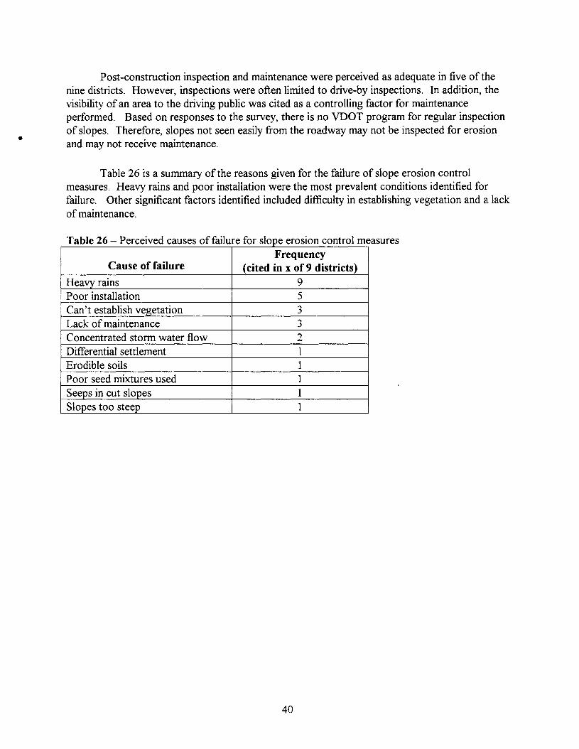
•
Post-construction inspection and maintenance were perceived as adequate in five of thenine districts. However, inspections were often limited to drive-by inspections. In addition, thevisibility of an area to the driving public was cited as a controlling factor for maintenanceperformed. Based on responses to the survey, there is no VDOT program for regular inspectionof slopes. Therefore, slopes not seen easily from the roadway may not be inspected for erosionand may not receive maintenance.
Table 26 is a summary of the reasons given for the failure of slope erosion controlmeasures. Heavy rains and poor installation were the most prevalent conditions identified forfailure. Other significant factors identified included difficulty in establishing vegetation and a lackof maintenance.
t I asuresf£ "I £" dT bl 26 Pa e - ercelve causes 0 al ure or s ope erosIon con ro meFrequency
Cause of failure (cited in x of 9 districts)Heavy rains 9Poor installation 5Can't establish vegetation 3Lack of maintenance 3Concentrated storm water flow 2Differential settlement 1Erodible soils 1Poor seed mixtures used 1Seeps in cut slopes 1Slopes too steep 1
40

Other Comments About Slope Erosion
The final question of the survey was, "Please provide any other comments you would liketo make about slope erosion." The responses to this question varied, as shown in Table 27.
t thT bl 27 Ra e - esponses 0 e conc u lng ques IonPlease provide any other comments you would like to make about
District slope erosion.Bristol None.
Culpepper We need guidance on seed/fertilizer criteria for different soils.Right-of-way constraints are a significant influence on what's done forerosion control.
Fredericksburg The combined efforts of maintenance, construction, and design personnelare needed to prevent slope erosion.
Lynchburg None.
Northem Virginia We need to allow limited use of sod in urban areas.Richmond The standard seeding rate (i.e., pounds of seed and additive per acre)
should be increased.Salem Leave room for engineering judgement.
Staunton Need to balance spending versus the end achieved, and balance cost versusaesthetics and public acceptance. Public perception is very important.Safety: Check dams in ditches may be a safety hazard to the drivingpublic.
Suffolk VDOT should develop a method to prevent accepting projects fromcontractors when vegetation is not established.
41

Erosion Control Practices in Surrounding States
In addition to evaluating the standard of practice for slope erosion control within VDOT,the Departments of Transportation for the states surrounding Virginia were also contacted. DOTpersonnel in Maryland, West Virginia, Kentucky, Tennessee, and North Carolina were asked toprovide feedback. The Federal Highway Administration was also contacted. The followingsubsections provide a summary of the responses.
Maryland
Maryland has a progressive reputation for erosion control. Montgomery County inMaryland adopted the first sediment control program in the United States in 1965. In 1969, theMaryland legislature required the use of sediment control measures in the Patuxent Riverwatershed, and in 1970 adopted a comprehensive sediment control program. (Smith and Ports,1976). Mr. Ed Obrec from the Maryland State Highway Administration filled out the survey.The state of practice for Maryland appears to be very similar to that of Virginia. A summary ofsignificant points from the Maryland response is provided below.
Erosion control was perceived to be very important. However, as in VDOT, no specificdesign procedures were used. The experience of the design engineer with the effectiveness of aspecific method was cited as one of the most important factors relied upon during the designprocess. Maryland has a centralized design bureau. Vegetation was identified as the single mostimportant method of erosion protection. Mulches were almost always used as an aid toestablishing vegetation. Other methods of erosion protection such as geosynthetic rolled erosioncontrol products and rip-rap were used less than 10 percent of the time. Silt fences were theerosion control practice of choice, with hay bales, brush layers, sediment traps, and sedimentponds used to a lesser extent.
While Maryland uses a central design bureau, districts throughout the state performinspection and maintenance. The inspection of erosion controls during construction and postconstruction was not believed to be adequate. Some problems were noted to have been foundonly after they became serious. The failure of erosion control measures was attributed to: 1)inadequate design, 2) poor establishment of vegetation, 3) erodible soils, 4) excessive rains, or 5)subsequent development of adjacent areas. Post-construction maintenance, however, wasbelieved to be adequate.
West Virginia
Mr. Glenn Sherman, the Geotechnical Group Leader for the West Virginia Department ofTransportation (WVDOT), provided a summary of the erosion control practices used along WestVirginia highways. No design procedures were used for erosion control measures, and erosionwas perceived as a construction problem, not generally considered during design. Erosion wasnoted as more of a problem in cuts in soft shale material and on high embankment fills. Duringconstruction, seeding and mulching were the predominant erosion controls used. Moreover,geosynthetic rolled erosion control products were not used for large areas, but were used in
42

ditches at the interface of cut and fill sections. Rip-rap was used to construct repairs in areaswhere erosion occurred.
West Virginia has an approved listing for erosion control products. Selection of productsfor the list is made by committee. Field testing has not generally been conducted in the past,although a testbed for some of the newer erosion control methods is proposed along Corridor H,an 128.7 kIn (80 mile) stretch from Elkins, West Virginia, toward Strasburg, Virginia.
Kentucky
Kentucky provided the largest response to the survey outside of Virginia. Five responseswere returned. Mr. Gary Poole, chief drainage engineer for the Kentucky Transportation Cabinet(KYTC) coordinated the Kentucky response. The design for slope erosion control wasaddressed in one of the five returned surveys, while the other four responses provided informationon construction, maintenance, and performance of erosion control measures.
The Kentucky Department of Transportation (KYDOT) recently started incorporatingerosion control plans into project plans. KYDOT's guidance for design can be found on theinternet at \¥ww.kvtc.state.ky.us/design as design memorandum number 8-98. The designmemorandum contains information on Best Management Practices (BMPs) similar to Virginia(1992). District offices and consultants perform slope erosion protection design, with designreview provided by the drainage section in the central office. While slope erosion control wasperceived as very important, no specific design procedures were reported.
A wide variety of erosion control measures are used in Kentucky. The usage rate forvegetation and loose mulches was 100 percent, and erosion control nettings and meshes had ausage rate of70 percent. Erosion control blankets and mattings were used at rates of30 and 50percent, respectively. The reported frequency of use for rip-rap was 80 percent. Limited use ofgeocellular containment systems, fiber roving systems, and articulated blocks was also reported.Silt fences and hay bales had a reported usage rate of 100 percent, while no use ofbrush layerswas reported. KYDOT makes extensive use of terraces. Sediment traps, check dams, andsediment basins or ponds had a usage rate of 60 percent.
All respondents reported adequate construction inspection of slope erosion controlmeasures. The time required for inspection, however, was reported as varying from 1 minute peracre to as much time as needed. Opinions about post-construction inspection and maintenancewere mixed; responses varied from not adequate to adequate. One response provided a specificdescription: inspection and maintenance occurred every 2 months for the first 6 months afterconstruction, with no inspection or maintenance performed after 6 months.
Tennessee
Mr. Bill Trolinger, the Assistant State Materials Engineer for the Tennessee Departmentof Transportation (TDOT) filled out and returned the survey. Slope erosion control wasperceived as important and concerns about erosion were noted as sometimes affecting the length
43

and steepness of cuts and fills. However, material types were perceived as having a greaterimpact on allowable slope height and inclination. Flattening slopes and providing erosionprotection were cited as design procedures to prevent erosion. The effect of slope length onerosion was highlighted. Maximum slope lengths in the context of slope erosion control are 7.62meters (25 ft). Techniques used to reduce slope length for erosion control included benches or aline of straw bales.
Tennessee reported the lowest use of vegetation, at a rate of80 percent. The use ofgeosynthetic rolled erosion control products was one of the highest found from the survey, with ausage rate of 50 percent (Kentucky had the highest reported rate of70 percent). Silt fences,terracing, sediment traps, and sediment ponds were practices always used for erosion control.The 100 percent usage rate for terracing, sediment traps, and ponds was the highest in the survey.
Construction inspection of erosion control was reported as probably not adequate. Noresponse was made regarding post-construction inspection and maintenance. However, improperinstallation, use of improper methods for the conditions, or extreme rainfall events were cited ascommon reasons for the failure of erosion control.
North Carolina
North Carolina has apparently unified design and construction inspection for erosioncontrol within a single section/division. Mr. Randy Wise, the Soil and Water EngineeringSupervisor for the North Carolina Department of Transportation (NCDOT) completed the surveyfor NCDOT. Slope erosion control was perceived as very important. Design procedures toreduce slope erosion were very similar to those in Virginia. Priorities for design to control slopeerosion included minimizing flows from adjacent watersheds by diversion, the use of slope drainsto control concentrated flows, and establishing vegetation. A design storm with a 10-yearrecurrence interval was used to size slope drains and ditches. Mass stability was noted as theprimary factor controlling slope geometry, although terraces were used to reduce the slope lengthas an erosion control measure.
Stable vegetative cover was noted as a principal design goal and a usage rate of 100percent were reported. Erosion control blankets and mats, fiber roving systems, and rip-rap wereused on 50 percent of the projects. Rip-rap was specifically mentioned as a design alternative tovegetative cover. The rate of 50 percent was the highest rate reported for erosion controlblankets and mats. In addition, North Carolina was the only state to report significant use offiberroving systems. Records of the effectiveness of a product or practice are kept so that designpractices can be adjusted based on actual field performance.
An exposed area limit of 4050 to 6070 square meters (1 to 1.5 acres) and staged seedingfor slopes in 6.10 to 9.14 meter (20 to 30 ft) vertical increments were reported. Constructioninspection of erosion control is centralized in North Carolina. Seven engineers and seventechnicians work with the goal of inspecting each project every two weeks during construction.The criteria for post-construction inspection were not reported, and the respondent was unsure ifpost-construction maintenance was adequate. Poor vegetation, large storm events (storms with a
44
recurrence interval of 25 years or more), and improper construction techniques were mentioned asreasons that slope erosion control measures fail.
Federal Highway Administration
Federal Highway Administration (FHWA) personnel were contacted about slope erosioncontrol practices. Four individuals were interviewed. Mr. Jerry DiMaggio and Dr. Chris Dumas,technical experts for geotechnical engineering within the FHWA, provided a list of contacts in theFHWA and state DOT's. Mr. Jorge Pagan and Mr. Philip Thompson were also interviewed. Mr.Pagan is a FHWA technical expert for erosion along stream channels and for bridge scour, andMr. Thompson is the senior hydraulics engineer for the FHWA.
Based on a phone conversation with Mr. Pagan on May 12, 1999, there are apparently nodesign procedures promoted by the FHWA for selecting slope erosion control measures.However, the FHWA does have recommended procedures and specifications for the use ofgeosynthetic rolled erosion control products, silt fences, and rip-rap, as well as recommendedBest Management Practices (BMPs) for sediment and erosion control. Sample specifications fromthe FHWA work can be found in Berg (1993), Holtz et al. (1997), and Holtz et al. (1998). Mr.Pagan also recommended the use of Chen and Cotton (1988) for the design of channel linings.Mr. Pagan suggested contact with Mr. Philip Thompson, senior hydraulic engineer with theFHWA. Mr. Thompson was interviewed by phone on May 26, 1999. He confirmed Mr. Pagan'sassertion that no specific procedures are used by the FHWA for the design of slope erosioncontrol.
Both the FHWA and the American Association of State Highway and TransportationOfficials (AASHTO) do provide guidance on drainage and sediment and erosion control(AASHTO, 1999 and FHWA, 1995). The Best Management Practices (BMPs) described in thesedocuments are similar to the information found in the Virginia Sediment and Erosion ControlHandbook (Virginia, 1992).
45

Procedures for Selecting Erosion Control Methods
VDOT designers typically select and specify a level of protection based on experience withlocally varying conditions and principles of erosion control. Once a design has been developed,contractors then have responsibility for providing the specified cover type. Contractors canchoose from a list of VDOT approved products to provide the needed erosion protection. Thecontractor is accountable for installation and short-term maintenance, while the responsibility forconstruction observation and long-term maintenance remains with VDOT. For VDOT, theproblems associated with this process include identifying problematic site conditions, selecting anappropriate level of erosion protection, maintaining a suitable list of approved products, andperforming adequate inspection and maintenance.
The selection of appropriate and cost-effective erosion control methods is a real problemfor design engineers. In most other situations, engineering designs are based on rationalprocedures, reference to previous work, published standards, or the testing of alternatives.However, the state of practice for erosion control design is not well developed. For example, theAmerican Society of Testing and Materials (ASTM) is in the process of developing standards forerosion and sediment control, but this work is not yet complete.
Currently, information about erosion control methods is based on data from manufacturersor from field tests. The Texas Department of Transportation (TxDOT) uses a test program toselect geosynthetic rolled erosion control products for addition to their list of approved products.While data from the TxDOT program is primarily applicable to local conditions, the Texasprogram is a model for selection of products based on performance observations.
In addition to the use of published standards or test programs, the selection of a specificproduct can also be based on decision analysis techniques. Decision analysis techniques employweighting of product characteristics that provides a ranking of expected performance. Theranking can be used for product selection. A disadvantage of these techniques is the lack of casehistories and experience using decision analysis for selecting erosion control methods.
The universal soil loss equation (USLE) can be used as a design tool for selecting erosioncontrol methods. Advantages of use of the USLE are that it provides a rational basis forevaluating site condition and is well accepted for predicting erosion rates. It must be recognized,however, that the USLE was developed for agricultural use and that its application to highwayslopes represents an extension. To the authors' knowledge, the USLE is not routinely used forslope erosion design by any state department of transportation or by the FHWA. Neither has thereliability of the USLE for slope erosion design been comprehensively evaluated by researchstudies.
The following subsections contain descriptions of principle based design, use of theUSLE, field testing programs such as the TxDOT program, decision analysis techniques, and theongoing ASTM effort. Design examples are provided for the USLE and decision analysis.
46

Regardless ofwhat methods are used for selection, cost will be a factor. Methods thatprovide a high level of protection often have higher costs. Examples of high cost/high protectionmethods are rip-rap, gabions, and articulated block systems. Table 28 contains a summary ofcosts that may prove helpful during preliminary design. The costs shown include installation andhave been rounded to the nearest dollar.
t I th d dT bl 28 C ta e - os comparIson or common erOSIon con ro me o san prac IcesErosion control method or practice Installed Cost
Seed (after Virginia, 1992) < $ 1 / SYLoose mulches (after Virginia, 1992) < $ 1 / SYTackifiers (after Virginia, 1992) < $ 1 / SYHydraulic mulches (Means, 1993) < $ 1 / SYErosion control nets (Means, 1993) $ 1 / SYErosion control meshes (Means, 1993) $2/SYErosion control blankets (Means, 1993) $4/SYErosion control mats (Theisen and Richardson, 1998) $ 6 to 15 / SYGeocellular containment systems, vegetated (Theisen and Richardson, $ 20 to 40 / SY1998)Geocellular containment systems, concrete filled (Theisen and $ 30 to 60 / SYRichardson, 1998)Fiber roving systems, UV stabilized (Theisen and Richardson, 1998) $ 1 to 2 / SYRip-rap (Theisen and Richardson, 1998) $ 15 to 80 / SYRip-rap (Means, 1993) $ 50 to 60/ SYGabions (Theisen and Richardson, 1998) $ 45 to 75 / SYGabions (Means, 1993) $ 33 to 80 / SYFabric formed revetments (Theisen and Richardson, 1998) $ 15 to 30 / SYArticulated blocks (Theisen and Richardson, 1998) $ 40 to 60/ SYSilt fences (Means, 1993) $ 1 to 2 / LFSilt fences (Virginia, 1992) $ 2 to 5 / LFStraw or hay bales (Virginia, 1992) $ 3 to 6 / LFBrush barrier (Virginia, 1992) $ 2 to 5 / LFCut drainage ditch (Means, 1993) < $ 1 / LFDiversion ditch (Virginia, 1992) $ 3 to 12 / LFClean out of ditch (Means, 1993) < $ 1 / LFRock check dams (Virginia, 1992) $13 t020/tonSediment traps (Virginia, 1992) $ 500 to 2,100/ unitSediment basins (Virginia, 1992) > $ 15,000 / unitSediment removal (Virginia, 1992) $5tol0/CYNotes on units: SY - square yard (1 SY = 0.8361 m2
), LF -linear foot (1 LF = 0.3048 m), andCY - cubic yard (1 CY = 0.7646 m3
)
47

Principle Based Design
As described above, VDOT currently uses a design philosophy of slope erosion control bydiverting and controlling runoff: managing concentrated flows, and establishing vegetation onslopes. This is principle based design. Principle based design is widespread, based on our surveyof surrounding states and the FHWA, and has been successfully used for the design for slopeerosion control. According to Goldman et al. (1986), the principles for erosion control are:
1) fit development to the terrain,2) time construction activities to reduce soil exposure,3) retain existing vegetation.,4) use erosion control methods and practices,5) divert runoff away from denuded areas,6) minimize the length and steepness of slopes,7) keep runoffvelocites low,8) manage concentrated flows,9) trap sediement on site., and10) inspect and maintain erosion control measures.
Tables 29, 30, and 31 provide guidelines for the use of erosion control methods andpractices (item 4 in the above list) in principle based design.
Success of principle based design depends on the knowledge, judgement, and experienceof the designers. In a large organization like VDOT, designers' knowledge can be expanded bygood record keeping and sharing experience across districts. A proposed format for recordkeeping is included in Appendix C. Compilation and distribution of this information from VDOTprojects across the Commonwealth would provide a good basis for improving VDOT's principlebased design strategy.
Using the USLE as a Design Tool
Rational selection of a method for erosion control is difficult because of the variety offactors that must be considered. These factors include the physical characteristics of the site,characteristics of an erosion control method, costs, and construction and maintenance practices.The physical factors for the site environment, topography, and surface cover can be assessedusing the universal soil loss equation (USLE), as described previously in this report. Figure 7 is aflowchart for the general use of the USLE. To highlight the use of the USLE as a design tool, theU.S. 29 bypass embankments near Madison Heights, northeast ofLynchburg, Virginia will beused as a design example. While construction of this project is ongoing, work on the proposedembankment has not begun. The embankments will be constructed using micaeous residual soilfill, which is known for high erodibility.
48

Table 29 - Summary of vegetatIve methods for erOSIon protectIon on soil slopesMethod Guidelines for use
Loose mulches • Used to protect seeds and ground surface• Long fiber length is primary advantage, more effective than
hydraulic mulches• Must be held in place
Hydraulic mulches
Tackifiers
• Used to protect seeds and ground surface• Easy application is primary advantage• Must be held in place• Used to hold seed and mulches in place• Use for slopes at 2H: 1V or flatter 1
• Should not use on long slopesErosion control nettings and • Used to hold seed and mulches in placemeshes • Use for slopes at 3H: 1V or flatter 2
• Good installation requiredErosion control blankets
Erosion control mattings
Geocellular containmentsystems
Fiber roving systems
Live planting methods
• Provides temporary erosion protection• Use for slopes at 2H: 1V or flatter 2
• Good installation required• Generally correlates to VDOT's EC-2• Provides long-term erosion protection• Use for steep slopes• Good installation required• Generally correlates to VDOT's EC-3• Provides long-term erosion protection• Can be combined with other methods• Use for steep slopes• Good installation required• Can provide long-term protection• Amount of protection can be tailored• Use for slopes at 2H: 1V or flatter 3
• Provides rapid establishment of vegetation• Can be combined with other methods
1 Based on information from Miller et al. (1996) and interviews with state DOTs.2 According to Koerner and Carson (1998).3 Based on information from Theisen (1992).
49

Table 30 - Summary of armonng methods for erosion protection on soil slopesMethod Guidelines for use
Rip-rap
Gabions
Fabric formed revetments
Articulated blocks
• Provides long-term protection• Use for severe conditions• Can be combined with live plantings• Use filter layer below rip-rap• Provides long-term protection• Use for severe conditions• Can be combined with live plantings• Can act as structural building blocks• Use filter layer below gabions• Provides long-term protection• Use for severe conditions• Use a filter layer below FFRs• Provides long-term protection• Use for severe conditions• Can be combined with live plantings• Use filter layer below articulated blocks
50
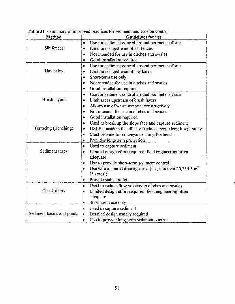
Table 31- Summary of improved practices for sediment and erosIon controlMethod Guidelines for use
• Use for sediment control around perimeter of siteSilt fences • Limit areas upstream of silt fences
• Not intended for use in ditches and swales• Good installation required• Use for sediment control around perimeter of site
Hay bales • Limit areas upstream of hay bales
• Short-term use only• Not intended for use in ditches and swales• Good installation required• Use for sediment control around perimeter of site
Brush layers • Limit areas upstream ofbrush layers• Allows use of waste material constructively• Not intended for use in ditches and swales• Good installation required• Used to break up the slope face and capture sediment
Terracing (Benching) • USLE considers the effect of reduced slope length separately• Must provide for conveyance along the bench• Provides long-term protection• Used to capture sediment
Sediment traps • Limited design effort required, field engineering oftenadequate
• Use to provide short-term sediment control• Use with a limited drainage area (i.e., less than 20,234.3 m2
[5 acres])• Provide stable outlet• Used to reduce flow velocity in ditches and swales
Check dams • Limited design effort required, field engineering oftenadequate
• Short-term use only• Used to capture sediment
Sediment basins and ponds • Detailed design usually required• Use to provide long-term sediment control
51

Start
Detennine site location and soil type
Detennine design values• Soil loss rate, A (page 53)
• Rainfall factor, R (Figure 2)• Soil erodibility factor, K (Figure 3)
Estimate slope geometry• Slope factor, S (Equations 2-4)• Length factor, L (Equation 5)
Use the USLE to estimate the requiredcover and practice factors, C and P (Equation- 8)
Select erosion protection based on the requiredvalues of the cover and practice factors
(Tables 6, 7 and 8).
Check
No • CPrequiredVS, CPprovided
• Other constraints(e.g., right-of-way, cost, etc.)
OK?
Yes
Figure 7 - Flowchart for erosion control design using the USLE
52

Selection ofDesign Values
A critical decision when using the USLE as a design tool is the amount of acceptableerosion. Smith and Ports (1976) describe natural erosion rates as being on the order of 0.045kg/m2/year ( 0.2 tons per acre per year) for forest land and 0.023 to 0.226 kg/m2/year (0.1 to 1.0tons per acre per year) for a stable, protected watershed. Typical rates for agricultural erosionrange from 0.068 to 1.36 kg/m2/year (0.3 to 6.0 tons per year per acre). Theisen and Richardson(1998) state that for landfill final cover the maximum allowable erosion rate is 0.45 kg/m2/year (2tons per acre per year). In addition to describing natural erosion rates, Smith and Ports (1976)also recommend acceptable erosion rate values for application along highways. They recommenddesign values of3.39 kg/m2/year (15 tons per acre per year) during construction and 1.13kg/m2/year (5 tons per acre per year) for post-construction sites. For construction projects with aduration of more than 2 years, the lower rate of 1.13 kg/m2/year (5 tons per acre per year) isrecommended. Wischmeier and Smith (1978) also recommended a rate of 1.13 kg/m2/year (5tons per acre per year) for construction projects. A value of 1.13 kg/m2/year (5 tons per acre peryear) will be used for the Madison Heights design example in accordance with therecommendations of Smith and Ports (1976).
As described previously, the rainfall factor, R, can be selected based on isoerodent mapsas shown in Figure 2. Using Figure 2, a R-value of 175 can be found for the Madison Heightsarea. In addition, Table 2 provides a range of annual values for the rainfall factor, R forLynchburg, Virginia. The observed range for the 22 year observation period varied between 64and 366. Annual values with a probability ofnon-exceedance of 50, 75 and 95 percent are 164,232, and 324, respectively. Because most sites do not have such detailed·information, and togeneralize the design example, the value of 175 from Figure 2 will be used.
The soil erodibility factor, K, has also been described previously. Residual soils for theMadison Heights project are described by Scarborough et al. (1998). Two micaeous residual soilswere found: a reddish, sandy elastic silt and a brown, silty sand. In the following discussion thesesoils are referred to as the red and brown soils. Values for the K-factor can be found using thenomograph in Figure 3. Table 32 shows the soil characteristics used with Figure 3 to select theK-factor. The soil erodibility factors found were 0.47 and 0.29 for the red and brown soils,respectively. The higher proportion affine grained material in the red soil is the most significantfactor in the difference for the estimated soil erodibility factors
Table 32 - Information used to determine the K-factor for the red and brown soilsCharacteristic Red soil Brown soil
Percent silt & very fine sand 50 30Percent sand 50 70Percent organic content 0 0Soil structure Very fine granular Fine granularPermeability Slow Slow to moderateSoil erodibility factor, K 0.47 0.29
53

Since the red and brown soils are not expected to be separated during construction ofembankments, the higher value for erodibility of the red soil (K = 0.47) will be used for this designexample.
Scarborough et al. (1998) found that at Madison Heights, for a 27.43 meter (90 ft) highslope constructed using either the red or brown soil, an inclination of 2.25H: 1V was required toprovide a long-term factor of safety of 1.3 against mass instability. Steeper slopes would requirereinforcement to be stable. We understand that VDOT intends to construct the Madison Heightsproject with slopes of2.5H: 1V.
A range of slope inclinations from 3H: 1V to 1.5H: 1V are used in the calculations thatfollow. The empirical equations (Equations 2 to 5) for the topographic factors shown previouslywere used to calculate values ofL and S. Tables 33 and 34 show the resulting combined valuesfor the topographic factor, LS. Table 33 is based on moderate susceptibility to rill erosion, whilethe results in Table 34 are based on an assumption of high susceptibility for rill erosion. In Tables33 and 34, values ofLS are provided for slope lengths less than those corresponding to the full27.43 meter (90 ft) embankment height. The shorter slope lengths are provided so that the impactof terracing can be evaluated.
Table 33 - Calculated values for the topographic factor, LS, assuming moderate011 0 ~ h M dO H 0 h b nkmrl erosIon or t e a Ison elg, ts em a ents
Value of the topographic factor, LSMaximum Horizontal slope length, meters (feet)
slope length 1 13.72 27.43 41.15 54.86 68.58 82.30Slope inclination meters (feet) (45) (90) (135) (180) (225) (270)
3H:IV 82.30 (270) 3.5 5.6 7.3 8.8 10.3 11.62.5H:IV 68.58 (225) 4.1 6.6 8.8 10.6 12.4 ---2H:IV 54.86 (180) 5.0 8.2 10.8 13.2 --- ---
1.5H:IV 41.15 (135) 6.2 10.3 13.8 --- --- ---I Maximum horizontal slope length for a 27.43 meter (90 ft) high embankment
Table 34 - Calculated values for the topographic factor, LS, assuming high rill. D h M dO H 0 h b nkmerosIon or t e a Ison elg. ts em a ents
Value of the topographic factor, LSMaximum Horizontal slope length, meters feet)
slope length 1 13.72 27.43 41.15 54.86 68.58 82.30Slope inclination meters (feet) (45) (90) (135) (180) (225) (270)
3H:IV 82.30 (270) 3.3 5.7 7.9 10.0 11.9 13.32.5H:IV 68.58 (225) 3.9 6.8 9.5 12.0 14.3 ---2H:IV 54.86 (180) 4.7 8.4 11.7 14.8 --- ---
1.5H:IV 41.15 (135) 5.9 10.6 14.8 --- --- ---I Maximum horizontal slope length for a 27.43 meter (90 ft) high embankment
54

Both the red and brown soils are micaeous. Micaeous soils were specifically identified ashighly erodible in our VDOT erosion survey. To account for high erodibility, the slopesconstructed with these micaeous soil are judged to have a high susceptibility to rill erosion.Therefore, the values for the topographic factor, LS, shown in Table 34 will be used.
Required Cover and Practices to Control Erosion
The USLE can be used to select the cover and practice factors required to limit the rate oferosion to an acceptable value (Wischmeier and Smith, 1978). Rearranging the terms of theUSLE, Equation 8 shows how the required cover, C, and practice, P, factors can be found:
C x P = A / (R x K x L x S) (8)
where A is the acceptable erosion rate of 1.13 kg/m2/year (5 tons per acre per year), R is therainfall factor with a design value of 175 for the Madison Heights U.S. 29 bypass project area, Kis the soil erodibility factor with design value of 0.47, and LS is the topographic factor withdesign values shown in Table 34. Using a spreadsheet, required values of the cover and practicefactors can be easily found using Equation 8. Table 35 contains acceptable values of the coverand practice factor product for the slopes at Madison Heights.
Table 35 - Maximum allowable values of the cover and practice factor product for theM d" H" ht b k ta Ison elg. s em an men s
Value ofe PHorizontal slope length in meters (feet)
13.72 27.43 41.15 54.86 68.58 82.30Slope inclination (45) (90) (135) (180) (225) (270)
3H:IV 0.019 0.011 0.008 0.006 0.005 0.0042.5H:IV 0.016 0.009 0.006 0.005 0.004 ---2H:IV 0.013 0.007 0.005 0.004 --- ---
1.5H:IV 0.010 0.006 0.004 --- --- ---
An example calculation to produce one of the entries in Table 35 is shown below. Thisexample is for a 27.43 meter (90 ft) high slope with an inclination of2.5H:IV and horizontalslope length of68.58 meters (225 ft). The calculation using Equation 8 is shown below. Note thatusing the metric value of A (1. 13 kg/m2/year) will yield incorrect values for the cover and practicefactor product.
ex p = A = 5.0 = 0.004RxKxLS 175xO.47xI4.3
Selected values for C and P from Tables 6, 7, and 8 are reproduced in Table 36. Table 36also contains expected installation costs for the method or practice from Table 28.
55

The maximum allowable CP product of 0.004 is not provided by any single control listedin Table 36. Therefore, a combination of controls must be applied to produce an acceptable valueofCP.
d tf tfT hi 36 Sit da e - e ec e va ues 0 cover ac or, prac Ice ac or, an cosCover Practice
Method Factor, C factor, P Cost CommentSecond year grass 0.01 --- < $1 / SY ---Hay mulch 0.45 kg/m2 0.05 --- < $1 / SY Should not be used for(2 tons/acre) slopes steeper than 2H: 1VHydraulic mulch 0.40 kg/m2 0.10 --- < $1 / SY Should not be used for(1.75 tons/acre) slopes steeper than 2H: 1VGeosynthetic erosion 0.02 --- $4/ SY Should not be used forcontrol blanket slopes steeper than 2H: 1VGeosynthetic erosion 0.05 --- $6-15 / SY No published limitation oncontrol mat slope steepnessFully vegetated erosion 0.005 --- $6-15 / SY No published limitation oncontrol mat slope steepnessRip-rap, crushed stone, 0.02 --- $15-80 / SY C-factor based on 2H: 1V54.24 kg/m2 (240 tons/acre) slope inclinationBare slope surface,trackwalked up and down --- 0.9 --- ---slopeTerracing, slope length less --- 0.1-0.18 --- Also reduces slope lengththan 33.53 meters (110 ft) (Wischmeier and Smith,
1978)Terracing, intermediate --- Interpolated ---slope lengthTerracing, slope lengthgreater than 91.44 meters --- 1.0 ---(300 ft)Note on units: SY - square yard (1 SY = 0.8361 m2
)
One possible approach to erosion control for this example would be to construct theembankment with a terrace at mid-height on the slope so that the slope height becomes 13.7meters (45 ft) for purposes of erosion control design. At this height, the horizontal slope lengthbecomes 34.2 meters (112.5 ft) for a 2.5H: 1V slope inclination. Applying Equations 2 to 5 and 8,the maximum allowable value ofCP is 0.0074, which can also be obtained by interpolating thevalues in Table 35. The practice factor for this bench configuration can be obtained byinterpolating between the values listed in Table 36. Conservative interpolation yields a practicefactor of 0.19. Applying a practice factor of 0.19 to the maximum allowable CP value of 0.0074yields a maximum allowable C-factor of 0.039. From Table 36, it can be seen that a geosyntheticerosion control blanket with a C value of 0.02 is appropriate. Once vegetation becomesestablished, erosion should be further reduced, because second year grass has a C value of 0.01,as shown in Table 36.
56

In summary, this example slope erosion control design for a 27.43 meter (90 ft) highembankment at Madison Heights with 2.5H:1V side slopes consists of providing one bench atmid-height of the slope combined with an erosion control blanket on the slopes above and belowthe bench. According to the USLE, these control measures should result in an erosion rate lessthan 1.13 kg/m2/year (5 tons/acre/year).
Terracing the slope to reduce the slope length for the purpose of erosion control designincreases the overall horizontal length of the entire slope by the width of the terrace. Thus,terraces may conflict with other design constraints such as limited right-of-way, and thesepotential conflicts should be checked. Moreover, benches must slope along the length of theembankment to provide an outlet for drainage. On very long embankments, multiple benches maybe required to maintain consistent slope lengths for erosion control.
Only one possible design for slope erosion control was evaluated for the example of theMadison Heights embankments. Other combinations of surface protection and improvedpractices are available and could also provide adequate protection.
Field Testing Programs for Specific Products and Conditions
Field test programs have been implemented by the Texas Department of Transportationand the Colorado Department of Transportation. These programs, along with two other testprograms in Ohio and Wisconsin are described below.
The Texas Department of Transportation (TxDOT) developed a protocol and test facilityfor selecting geosynthetic rolled erosion control products for addition to a list of approvedproducts. The TxDOT program is described by Godfrey and McFalls (1992) and Northcutt(1993). Northcutt (1993) also provides a description of the program's first year results. Thisinformation has been incorporated into the descriptions of erosion control blankets and matsprovided previously.
In 1982, TxDOT's standard specifications described erosion control blankets in terms oftheir physical properties such as unit weight, thickness, tensile strength, and elongation. Theserequirements were very specific and limited the number of available products. In the early 1990's,TxDOT rewrote their standard specifications to include the following statement: "All soilretention blankets must be prequalified by the Director, Division ofMaintenance and Operationsprior to use." To satisfy the prequalification requirement, TxDOT established an ongoing formaltesting program to evaluate erosion control products. Manufacturers desiring to have productsapproved pay a testing fee and must submit materials for testing. One test cycle lasts 9 months,beginning in May and lasting until February. A product's ability to provide both slope protectionand channel lining protection is tested by TxDOT.
The TxDOT test facility evaluates the slope protection provided by candidate products inthe field on an actual embankment. The test embankment is ell-shaped, is 6. 71 meter (22 ft) high,and has a total length of267 meters (876 ft). The test embankment's side slopes were
57

constructed at inclinations of2H: 1V and 3H: 1V using two soils, a sandy soil and a clay soil. Thesoils were selected to be typical of conditions found in Texas. Rainfall simulators are used toapply controlled storm intensities and durations. TxDOT evaluates the slope protection providedin terms of two criteria: 1) the ability to prevent the loss of sediment, and 2) the ability toestablish permanent vegetative cover.
The TxDOT facility also has the capability to test the performance of flexible channelliners. Ten channels, four with slopes of3 percent and six with slopes of7 percent, are used forthe liner testing. Each channel has a uniform cross-section with side slopes of 3H: 1V. Flexiblechannel liners are evaluated using the tractive stress criteria (Equation 7).
The methodology used by TxDOT for the selection of approved products is based on themeasured performance of installed products over a 9-month period. It includes evaluation ofshort-term performance, prior to the establishment of vegetation, as well as performanceevaluations for long-term behavior with vegetation established.
The Colorado DOT is conducting a three year study of slope erosion control methods.The test location is along U.S. 40 over Berthod Pass. The highway was first built in the early1960's. Slopes consist of highly erodible soils with variable sized rocks. Erosion of the slopeshas apparently contributed to a long standing rockfall hazard for the highway. Methods used forrehabilitation of the slopes along the highway include: small retaining walls, concrete pavedditches, five different tackifiers, five different erosion control mats, two fertilizers, and two typesof mulch. Results of the three year project will become available sometime after the year 2000(FHWA, 1997).
Koerner and Carson (1998) and Cabalka and Clopper (1998) describe two other examplesof ongoing field test programs. Results from these studies are included in the sections on erosioncontrol blankets and mats. Koerner and Carson (1998) describe a program evaluating the longterm stability of geosynthetic clay liners for use in solid waste landfills. The study was conductednear Cincinnati, Ohio, and is sponsored by the USEPA. The liners were installed on 2H: 1V and3:H: 1V slopes. The surface of the test plots were protected with a variety of geosynthetic erosioncontrol products. Over the last 4 years, 15 erosion control blankets and turf reinforcement matshave been tested in a on-going study. Cabalka and Clopper (1998) describe an erosion testfacility in Rice Lake, Wisconsin, operated by the American Excelsior Company. This test facilitycan evaluate both slope protection and channel protection provided by erosion control products.Slope erosion plots were constructed with slopes at an inclination of 3H: 1V using an 0.46 meter(18 in) thick veneer of3 different soils. The trapezoidal channels were built with side slopes at2H: 1V and longitudinal slopes of 5 and 10 percent. The test procedures described by Cabalkaand Clopper (1998) have been submitted to ASTM committee D-18.25, Erosion and SedimentControl Technology, for possible inclusion in a final standard.
In addition to qualifying products for an approved list of materials, such as done byTxDOT, field tests provide excellent data for use by designers to evaluate the expectedperformance of potential erosion control methods. The applicability of this information can belimited by local conditions of the test. For example, data from climatic and physiographic
58

conditions in Texas may not be representative of erosive conditions in Virginia. However, generaltrends of effectiveness for specific conditions are applicable. The data used to develop the USLEcame from a systematic evaluation of similar tests on agricultural plots.
VDOT may wish to consider use of a test program as a tool to evaluate current andpotential erosion control products for the approved list of products. Appendix B contains thecurrent VDOT approved listing of erosion control blankets and mats.
Decision Analysis
Williams and Luna (1987) developed a decision analysis technique for the selection ofgeotextile drainage products. Their procedure was based on a weighting of productcharacteristics to provide a ranking of expected performance as a basis for product selection.Sprague and Paulson (1996) applied this methodology to the selection of erosion controlgeosynthetics.
The first step in applying the decision analysis procedure is to select performance criteria.Sprague and Paulson (1996) selected five parameters to act as a yardstick for evaluating erosioncontrol products:
1) sediment yield,2) vegetative enhancement,3) stability under flow,4) durability, and5) cost.
The five parameters are then ranked, with a performal1ce number assigned to each of thefive. Since five aspects of behavior were evaluated, the highest value assigned as a performancenumber is 5; the lowest value is 1. Table 37 contains an example of this initial ranking.
Table 37 - Example of assigning perfonnance numbers (after Sprague and Paulson,1996, with pennission of the International Erosion Control Association)
Proposed use of the erosion control methodCase 1 Case 2
Performance criteria Urban draina2e channel Rural highway slopeSediment yield 4 5Vegetative enhancement 5 3Stability under flow 4 1Durability 2 2Cost 1 4
For Case 1, the criteria of sediment yield and stability under flow are assumed to haveequal importance for selection. Therefore, they are assigned performance numbers with equalvalue.
59

The second step of the decision analysis procedure is to rank each product's performancein each of the performance categories. These assigned rankings are called the erosion controlindices. Again, just as with the performance number, the best performing product is assigned thehighest value of the erosion control index. In this step, the ranking may be broken down tocompare index properties, field test results, or other important factors such as ease of installation.
An example of assigning an erosion control index to four products in the performancecategory of sediment yield is shown in Table 38. The assessment is made by evaluating andranking the specific properties for each product, as described previously. The values are thentotaled, and the erosion control index is based on the totals. Higher totals indicate betterperformance.
thddf nkia e - xamp.e 0 ra ng specI c pro ucts an asslgmng e erosIon con ro In exPerformance criteria - Sediment yield
ErosionGround Short-term Long-term Control
Product ill Flexibility Cover Behavior behavior Total IndexProduct A 1 2 1 1 4 1Product B 2 4 3 1 10 3Product C 3 3 3 1 9 2Product D 4 2 4 1 11 4
T bl 38 E
While not shown here, a similar ranking procedure would be repeated for each of themajor performance categories. Sprague and Paulson (1996) provide examples of this. Anevaluation of vegetative enhancement might be performed by evaluating color, moistureabsorption, porosity, and thickness of the candidate products. Stability under flow might beevaluated based on the products' permissible tractive stress or velocity. An evaluation ofdurability could be based on the tensile strength, susceptibility to creep, or resistance toultraviolet degradation. The evaluation of cost could be based on installation costs andanticipated maintenance costs. Erosion control indices would be assigned to each product in eachperformance category.
The third and final step of the selection process is to calculate the suitability numher, asshown by Equation 9. Product selection can be based on high values of the suitability number.
Suitability number = .E {I + 0.5 (Performance number)] {Erosion control index] (9)
Table 39 shows an example of applying Equation 9 for the calculation of suitability numbers. Thisexample uses the performance numbers assigned from Case 2 in Table 37, and the erosion controlindices for sediment yield from Table 38. Values of erosion control indices for the otherperformance criteria were obtained in manner similar to that shown in Table 38.
60

bI ~T bl 39 Ea e - xamp e or ca cu atlng t e sUlta 1 tty num erSediment Vegetative Stability Durability Cost
Yield Enhancement under flowPerformance number Calculated
5 I 3 I 1 I 2 I 4 suitabilityProduct ill Assigned erosion control indices numberProduct A 1 2 1 4 4 30Product B 3 4 2 1 1 29.5Product C 2 3 3 1 1 24Product D 4 2 4 4 2 39
Based on the example shown in Table 39, Product D would be the most appropriateproduct selection with a suitability number of39. Products A, B, and C follow with suitabilitynumbers of 30, 29.5, and 24, respectively.
The decision analysis technique developed by Williams and Luna (1987) and adapted bySprague and Paulson (1996) to erosion control applications can provide a basis for the selectionof erosion control products. Justification for assigned values should be presented with the resultsof the analysis so that any partiality in weighting characteristics can be reasonably judged. Theoutcome of decision analysis techniques should be examined to see if the result is reasonable.
To the author's knowledge, the decision analysis approach has not been assessed byresearch studies, nor is it ro~tinely used by state departments of transportation or the FHWA.
Proposed ASTM Standard for Erosion Control Products
In 1996, the American Society of Testing and Materials (ASTM) established committeeD-18.25, Erosion and Sediment Control Technology, to develop standards for erosion andsediment control best management practices (BMPs). The committee plans to address materialcharacteristics, installation requirements, performance capabilities, and application guidelines.Cabalka (1999) reports that the proposed standard will be developed with ten sections. The tensections consist of the following:
1) Mulches and tackifiers,2) Erosion control blankets,3) Turf reinforcement matting,4) Articulating concrete block revetments,5) Gabions,6) Geocellular confinement materials,7) Fabric-formed concrete revetments,8) Sediment control,9) Terminology, and10) Soil bioengineering.
61

About 150 personnel are reported to be participating in committee D-18.25. Thesepersonnel represent government officials (including several DOT representatives), owners,designers, contractors, manufacturers, testing laboratories, colleges/universities, and industryassociations (Cabalka, 1999). A schedule for publication of the proposed standard has not beendeveloped.
Standard terminology, classifications, characteristics, and test methods are expectedbenefits of the new ASTM standard. The proposed standard should make it easier to evaluate theperformance claims made by manufacturers. However, the new standard is not likely to provide adesign method for slope erosion control.
CONCLUSIONS AND RECOMMENDATIONS
The erosion of soil slopes is a problem along Virginia's highways. Erosion of soil slopescan create safety hazards, such as undermined pavements. Environmental quality can also bereduced by the sediments from eroded slopes. Moreover, repair of eroded slopes can beproblematic due to restricted access and difficult working conditions. Such difficulties can resultin high costs for slope repair. Effective erosion protection can prevent or reduce the magnitude ofthese problems.
A research study was completed to assess the state of erosion control practice and todevelop recommendations for improving erosion control activities in VDOT. The followingsubsections present a summary of the work accomplished to achieve these objectives, the findingsof the research, and our recommendations.
Summary of Work Accomplished
An extensive literature review was conducted. In addition, a survey of the state ofpractice within VDOT was conducted by visiting each of the nine VDOT districts. The purposeof the survey was to gain an understanding of how VDOT designs, constructs, and maintainserosion control measures for slopes. The state of practice within surrounding states and theFHWA was also assessed. The information from these sources was synthesized to produce thisreport, which include descriptions of erosion fundamentals, erosion control principles, erosioncontrol methods, and procedures for selecting erosion control methods. Design examples are alsoincluded.
Findings
The state of the art for design of slope erosion controls is not well developed. Moreover,based on our visits to each of the nine districts, it is clear that there are no specific quantitativedesign procedures currently in use within VDOT for slope erosion. However, slope erosion wasperceived as an important issue and a general design strategy was found. Designers generally tryto limit erosion by diverting runoff: controlling concentrated flows on slopes, and establishingvegetation. This is a practice of design by principle, a qualitative process that is heavily dependenton the experience of the designer.
62

We found that the design practices for the Departments of Transportation in thesurrounding states ofMaryland, West Virginia, Kentucky, Tennessee, and North Carolina, and forthe FHWA, are similar to those used in Virginia. All agencies currently use a principle andexperience based strategy for the design of slope erosion control.
We found that an alternative to principle based design of erosion control measures doesexist. This alternative employs the Universal Soil Loss Equation (USLE). The USLE is anempirical equation developed to predict erosion losses on slopes. The USLE was developed toquantitatively evaluate the impact that variation in five basic factors have on the rate of soilerosion. These five factors include:
1) the duration and intensity of rainfall,2) the type and erodibility of soil,3) the length and steepness of the slope,4) the type and extent of cover on the slope, and5) the type and extent of erosion control practices on the slope.
The USLE can be used as a tool for the design of erosion protection. A design example ispresented in this report.
Product specific values for the cover factors in the USLE are not generally available.Generic values are available, however, as shown in Tables 6 and 7. Field tests provide the bestinformation about product performance.
Although it shows promise as a design tool, it must be recognized that the USLE is notcurrently used by VDOT, the Departments of Transportation in surrounding states, or the FHWAfor slope erosion control design.
Regardless of the erosion control method selected, construction and maintenance practiceswill significantly affect field performance. Poor installation is a common problem duringconstruction. Moreover, a single storm event can degrade system performance. Thus, on-goingmaintenance is required. Lack of maintenance for installed erosion control methods has oftenbeen cited as a significant factor in reported failures. Personnel in 4 of 9 districts believedVDOT's current inspection and maintenance practices are not adequate.
We also found, based on our review of the state of practice, that VDOT personnelindicated a need for guidelines to address:
• The use of asphalt curbing and slope drains (from the Northern Virginia district).• Seed/fertilizer mixes and associated criteria for different soils (from the Richmond and
Culpepper districts).
63

• The use of sod for establishing vegetation in urban areas (from the Northern Virginiadistrict).
• Acceptance of projects from contractors when vegetation has not been established (fromthe Suffolk district).
Recommendations
We recommend that VDOT continue to use its principle and experience based designpractices across the Commonwealth. We also recommend that a system of documentation andcommunication be established within VDOT to enhance its principle based design. Appendix Ccontains a listing of elements that can be used to document slope erosion performance.Compilation and distribution of this information has the potential to improve the experience basenecessary for successful principle based design.
We also recommend that the USLE be used to complement VDOT's current designpractices. The USLE should be used because it is the best available tool, in our opinion, for thequantitative evaluation of slope erosion. VDOT should adopt guidelines for an acceptable soilloss rate for use with the USLE. Based on Smith and Ports (1976) and Wischmeier and Smith(1978), the following acceptable soil loss rates along highways are recommended:
• 3.39 kg/m2/year (15 tons per acre per year) for most construction,• 1.13 kg/m2/year (5 tons per acre per year) for construction projects with a duration of
more than 2 years, and• 1. 13 kg/m2/year (5 tons per acre per year) for post-construction sites.
We recommend that VDOT consider field testing of erosion control products and methodsto collect performance data in addition to that generated by the documentation described abovefor existing and future slope erosion control projects. The test results would be distributed withinVDOT to expand designers' experience base. One method for generating performance data is theuse of a field testbed, similar to that used by the Texas Department of Transportation, to prequalify erosion control products and to generate parameters for design. An alternative method forgenerating performance data is to incorporate erosion test sections on embankment constructionprojects. Two levels of performance tests could be performed. The most detailed level of testingwould allow assessment of the cover and practice factors for use with the USLE. Thebibliography from Wischmeier and Smith (1978) provides sources for guidance in performing thislevel of testing. Less rigorous testing would be similar to the pre-qualification testing performedby Texas. Godfrey and McFalls (1992), Northcutt (1993), Koerner and Carson (1998), andCabalka and Clopper (1998) describe this type ofyes/no testing.
VDOT should review and update their policies on slope erosion inspection andmaintenance. Personnel in 4 of the 9 VDOT districts believed the current inspection andmaintenance practices to be inadequate. Such a review and update could include a short courseon slope erosion control for project inspectors and establishing recommended frequencies forinspection during and after construction.
64
ACKNOWLEDGEMENTS
The Virginia Transportation Research Council and the Virginia Department ofTransportation provided funding for this work. In addition, Dr. Ed Hoppe of the VirginiaTransportation Research Council and Mr. Stan Rite and Mr. Charles McIver of the VirginiaDepartment of Transportation all made important contributions. We would also like to thank themany personnel in all nine VDOT districts, Maryland, West Virginia, Kentucky, Tennessee, NorthCarolina, and the FHWA who contributed their time and effort by responding to our request forinformation about slope erosion control.
REFERENCES
AASHTO, (1999). Model Drainage Manual, Metric. AASHTO Publication No. I-MD-I
Armstrong, J.J., and Wall G.J., (1991). Quantitative Evaluation of the Effectiveness ofErosionControl Materials. Proceedings ofConference XXII, International Erosion Control Association,Orlando, Florida, pp. 167-179.
Berg, R.R., (1993). Guidelines for Design, Specification, and Contracting ofGeosyntheticMechanically Stabilized Earth Slopes on Firm Foundations. FHWA Report No. FHWA-SA-93025,88 pg.
Cabalka, D., (1999). The Activities of ASTM Committee D-18.25 - Erosion and SedimentControl Standards for the Next Millennium. Transportation Research Board Annual Conference,Washington, D.C.
Cabalka, D., and Clopper, P., (1998). Performance Testing ofErosion Control BMPs at theErosion Lab. Geosynthetics in Foundation Reinforcement and Erosion Control Systems~ ASCE,Special Publication No. 76, pp. 103-115.
Cancelli A., Monti, R., and Rimoldi, P., (1990). Comparitive Study of Geosynthetics for ErosionControl. Proceedings ofthe 4th International Conference on Geotextiles, Geomembranes andRelated Products, A.A. Balkema, The Hague, pp. 403-408.
Carroll, R.G., Rodencal, J., and Collin, J.G., (1991). Geosynthetics in Erosion Control- ThePrinciples. Geosynthetics in Filtration, Drainage, and Erosion Control, Elsevier AppliedScience, pp. 187-198.
Carroll, R.G., and Theisen, M.S., (1990). Turf Reinforcement for Soft Armor ErosionProtection. Proceedings of the 4th International Conference on Geotextiles, Geomembranes andRelated Products, A.A. Balkema, The Hague, pp. 133-145.
Cazzuffi, D., Monti, R., and Rimoldi, P., (1991). Geosynthetics Subjected to DifferentConditions ofRain and Runoff in Erosion Control Application. Proceedings ofConference XXII,International Erosion Control Association, Orlando, Florida, pp. 193-208.
65

CE News, (1998). Erosion Control Products - A Comprehensive List. CE News, December, pp.56-57.
Chen, Y.H., and Cotton, G.K., (1988). Design ofRoadside Channels with Flexible Linings.FHWA, Hydraulic Engineering Circular No. 15, 112 pg.
Collin, J.G., (1996). Controlling Surficial Stability Problems ofReinforced Steepened Slopes.Geotechnical Fabrics Report, April, IFA!, pp. 26-29.
Duffy D.M., and Hatzell, H., (1991). The Use of Inorganic Surface Treatments to MitigateErosion. Proceedings ofConference XXII, International Erosion Control Association, Orlando,Florida, pp. 291-299.
FHWA, (1995). Best Management Practices for Erosion and Sediment Control. FHWAPublication No. FHWA-FLP-94-005.
FHWA, (1997). Colorado DOT Evaluates Erosion Control Methods. FHWA Western GeoNews, Vol. II, No.3, www.fhwa.dot.gov/bridge/gnews2-3.
Fitfield, J.S., (1991). What are Acceptable Sediment Yields from Sites Undergoing Construction?Proceedings ofConference XXII, International Erosion Control Association, Orlando, Florida,pp. 71-80.
Godfrey, S., and McFalls, J., (1992). Texas Department of Transportation and TexasTransportation Institute Field Testing Program for Slope Erosion Control Products, FlexibleChannel Lining Products, Temporary and Permanent Erosion Control Products. Proceedings ofConference XXIII, International Erosion Control Association, Reno, Nevada, pp. 335-339.
Goldman, S.J., Jackson, K., and Bursztynskky, T.A., (1986). Erosion and Sediment ControlHandbook. McGraw Hill.
Gray, D.H., and Leiser, A.T., (1982). Biotechnical Slope Protection and Erosion Control. VanNostrand Reinhold, 271 pg.
Gray, D.H., and Sotir, R.B., (1996). Biotechnical and Soil Bioengineering Slope StabilizationA Practical Guide for Erosion Control. John Wiley and Sons, 377 pg.
Holtz, R.D., Christopher, B.R., and Berg, R.R., (1997). Geosynthetic Engineering. BiTechPublishers Limited, 452 pg.
Holtz, R.D., Christopher, B.R., and Berg, R.R., (1998). Geosynthetic Design and ConstructionGuidelines. FHWA Report No. FHWA-HI-95-038, 460 pg.
66

Hunt, D., Austin, D.N., and Agnew, W., (1998). Vegetation Selection for Rolled ErosionControl Products. Geosynthetics in Foundation Reinforcement and Erosion Control Systems,ASCE, Special Publication No. 76, pp. 130-144.
Ingold, T.S., and Thomson, J. C., (1990). A Design Approach for Preformed Erosion ControlSystems, Proceedings ofthe 4th International Conference on Geotextile, Geomembranes, andRelated Products, A.A. Balkema, The Hague, pp. 375-380.
Koerner, G.R., and Carson, D.A., (1998). Geosynthetic Erosion Control Materials: A LandfillCover Field Study. Geosynthetics in Foundation Reinforcement and Erosion Control Systems,ASCE, Special Publication No. 76, pp. 77-91.Lentz, R.D., and Sojka, R.E., (1996). Polyacrylamide Application to Control Furrow Irrigationinduced Erosion. Proceedings ofConference XXVII, International Erosion Control Association,Seattle, Washington, pp. 421-429.
Means, (1993). Site Work and Landscape Cost Data, 12th Edition. R.S. Means Co. Kingston,MA, 405 pg.
Miller, J.T., Edberg, R., and Berry, A.M., (1996). Soil Tackifier Performance on an ExposedSlope, Proceedings ofConference XXVII, International Erosion Control Association, Seattle,Washington, pp. 447-453.
Northcutt, P.E., (1993). Field Performance Testing ofRoll-type Erosion Control Blanketsthrough the Erosion Control Field Laboratory, Proceedings ofConference XXVII, InternationalErosion Control Association, Seattle, Washington, pp. 187-193.
Rodencal, J., (1995). Design Considerations for Erosion Control Systems on MechanicallyStabilized Earth Slope Structures. Proceedings ofGeosynthetics '95, pp. 29-38.
Russ, T.H., (1993). Revegetation and Stabilization ofDisturbed Sites. Proceedings ofConference XXIV, International Erosion Control Association, Indianapolis, Indiana, pp. 423-430.
Scarborough J.A., Filz, G.M., Mitchell, J.K., and Brandon T.L., (1998). GeosyntheticReinforcement of the U.S. 29 Bypass Embankments, near Lynchburg, Virginia. A GeotechnicalEngineering Report, Virginia Tech, Ozawa Library No. 7859,900 pg.
Shaikh, A.., Ruff: J.F., and Abt, S.R., (1987). Surface Erosion of Compacted Pure Clay.Engineering Aspects ofSoil Erosion, Dispersive Clays and Loess. ASCE Special Publication No.10, pp. 67-78.
Smith, J.O., and Ports, M.A., (1976). Maryland Highway Erosion and Sediment Control:Evaluation and Future Directions. LandManagement of Waste Materials, Soil ConservationSociety of America, Ankeny, IA, pp. 262-277.
67

Sotir, R.B, Difini, J.T., and McKown, A.F., (1998). Partnering Geosynthetics and Vegetation forErosion Control. Geosynthetics in Foundation Reinforcement and Erosion Control Systems,ASCE, Special Publication No. 76, pp. 92-102.
Sprague, C.J., (1999). Green Engineering - Part Two. CE News, March, pp. 76-81.
Sprague, C.J., and Paulson, J.N., (1996). Project-specific Selection ofErosion ControlGeosynthetics. Proceedings ofConference XXVII, International Erosion Control Association,Seattle, Washington, pp. 215-226.
Theisen, M.S., (1992). Geosynthetics in Erosion and Sediment Control. Geotechnical FabricsReport, May/June, IFA!, pp. 26-35.
Theisen, M.S., and Carroll, R.G., (1990). TurfReinforcement - The "Soft Armor" Alternative.Proceedings ofConference XXI, International Erosion Control Association, Washington, D.C,pp. 257-270.
Theisen, M.S., and Richardson, G.N., (1998). Geosynthetic Erosion Control for Landfill FinalCovers. Geotechnical Fabrics Report, May, IFA!, pp. 22-27.
USDA, (1997). Predicting Soil Erosion by Water: A Guide to Conservation Planning with theRevised [lniversal Soil Loss Equation (RUSLE). U.S. Department of Agriculture, AgriculturalHandbook No. 703,384 pg.
Virginia (1992). Virginia Erosion and Sediment Control Handbook, Third Edition. VirginiaDepartment of Conservation and Recreation.
Wang, S., and Grubbs, K., (1992). Tennessee Erosion and Sediment Control Handbook.Tennessee Department ofEnvironment and Conservation, 65 pg.
Williams, N.D., and Luna, J., (1987). Selection of Geotextiles for Use with Synthetic DrainageProducts. Geotextiles and Geomembranes, International Geotextile Society, Vol. 5, No.1, pp.45-61.
Wischmeir, W.H., and Smith, D.D., (1978). Predicting Rainfall Erosion Losses - A Guide toConservation Planning. U.S. Department of Agriculture, Agricultural Handbook No. 537.
Wu, K.J., and Austin, D.D., (1992). Three-dimensional Polyethylene Geocells for ErosionControl and Channel Linings. Geotextiles and Geomembranes, International Geotextile Society,Vol. 11, pp. 611-620.
68

Appendix A
Questionnaire: Request for Information about Slope Erosion Control
Erosion Protection for Soil Slopesalong Virginia's Highways

Request for Information about Slope Erosion Control
Section 1 - General
1. What is your job title?
2. How long have you worked for VDOT?
3. How important is slope erosion control?
___________ years
Very important Important Somewhat important Not important
4. What percentage of your time is spent on slope erosion control issues? 0/0
Section 2 - Design
5. The length and steepness of cut and fill slopes are often determined by requirements relatedto road alignment, slope stability, and maintenance. Is slope erosion ever taken into accountwhen establishing the length and steepness of soil cut slopes or soil fill slopes?
Always Sometimes Never Don't Know
If you answered "always" or "sometimes," how do considerations of slope erosion influencedecisions about the length and steepness of soil cut slopes or soil fill slopes?
6. What personnel are responsible for design of slope erosion protection measures?
VDOTIVTRCIVT Slope Erosion Control Survey Page A - 2

7. What design procedures are normally employed for slope erosion protection measures?
8. When designing erosion control measures for a slope, is duration and intensity of rainfalltaken into account?
Always Sometimes Never Don't Know
If you answered "always" or "sometimes," how is duration and intensity of rainfall taken intoaccount?
9. When designing erosion control measures for a slope.. is soil type taken into account?
Always Sometimes Never Don't Know
If you answered "always" or "sometimes," how is soil type taken into account? We areespecially interested in knowing how you identify erodible soils.
VDOTIVTRCIVf Slope Erosion Control Survey Page A - 3

10. When designing erosion control measures for a slope, is slope length taken into account?
Always Sometimes Never Don't Know
If you answered "always" or "sometimes," how is slope length taken into accountf)
11. When designing erosion control measures for a slope, is slope steepness taken into account?
Always Sometimes Never Don't Know
If you answered "always" or "sometimes," how is slope steepness taken into account? Weare especially interested in learning your experience about the relationship between slopeinclination and erosion severity.
VDOT/VTRC/Vf Slope Erosion Control Survey Page A - 4
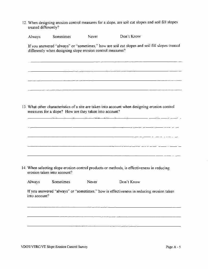
12. When designing erosion control measures for a slope" are soil cut slopes and soil fill slopestreated differently?
Always Sometimes Never Don't Know
If you answered "always" or "sometimes," how are soil cut slopes and soil fill slopes treateddifferently when designing slope erosion control measures?
13. What other characteristics of a site are taken into account when designing erosion controlmeasures for a slope? How are they taken into account?
14. When selecting slope erosion control products or methods, is effectiveness in reducingerosion taken into account?
Always Sometimes Never Don't Know
If you answered "always" or "sometimes,," how is effectiveness in reducing erosion takeninto account?
VDOT/VTRC/Vf Slope Erosion Control Survey Page A - 5

15. When selecting slope erosion control products or methods" is effectiveness in promotingvegetative growth taken into account?
Always Sometimes Never Don't Know
If you answered "always" or "sometimes,," how is effectiveness in promoting vegetativegrowth taken into account?
16. When selecting slope erosion control products or methods, is stability under water flow takeninto account?
Always Sometimes Never Don't Know
If you answered "always" or "sometimes," how is stability under water flow taken intoaccount?
VDOTIVTRC/Vf Slope Erosion Control Survey Page A - 6

17. When selecting slope erosion control products or methods, is durability taken into account!)
Always Sometimes Never Don't Know
If you answered "always" or '''sometimes,'' how is durability taken into account'")
18. When selecting slope erosion control products or methods, is cost taken into account'")
Always Sometimes Never Don't Know
If you answered "always" or "sometimes," how is cost taken into account?
19. What other factors are taken into account when selecting slope erosion control products ormethods? How are they taken into account?
VDOT/VTRCIVT Slope Erosion Control Survey Page A - 7

20. How frequently are the following slope erosion control methods used') Sometimes erosioncontrol methods are used in combination.. so the sum of your responses may exceed 100
%
Erosion control method Frequenc~'of use as percenta~e
Vegetation 100 90 80 70 60 50 ~O 30 20 10 0
Loose straw or hay mulch 100 90 80 70 60 50 ~O 30 20 10 ()
Hydro-seeding 100 90 80 70 60 50 ~O 30 20 10 0
Tackifier 100 90 80 70 60 50 40 30 20 10 (}
Geosynthetic erosion control netting 100 90 80 70 60 50 40 30 20 10 0
Geosynthetic erosion control meshes 100 90 80 70 60 50 40 30 20 10 0
Geosynthetic erosion control blanket 100 90 80 70 60 50 40 30 20 10 0
Geosynthetic erosion control matting 100 90 80 70 60 50 40 30 20 10 0
Geocellular containment system 100 90 80 70 60 50 40 30 20 10 0
Fiber roving systems 100 90 80 70 60 50 40 30 20 10 0
Rip-rap 100 90 80 70 60 50 40 30 20 10 ()
Gabions 100 90 80 70 60 50 40 30 20 10 0
Fabric fanned revetments 100 90 80 70 60 50 40 30 20 10 0
Articulated blocks 100 90 80 70 60 50 40 30 20 10 0
Silt fences 100 90 80 70 60 50 40 30 20 10 0
Hay or Straw bales 100 90 80 70 60 50 40 30 20 10 0
Brush layers 100 90 80 70 60 50 40 30 20 10 0
Terracing or benches on the slope 100 90 80 70 60 50 40 30 20 10 0
Sediment traps or check dams 100 90 80 70 60 50 40 30 20 10 0
Sediment basins or ponds 100 90 80 70 60 50 40 30 20 10 0
Selected definitions of these erosion control products and methods are provided on the next page.
VDOTIVTRCIVT Slope Erosion Control Survey Page A - 8
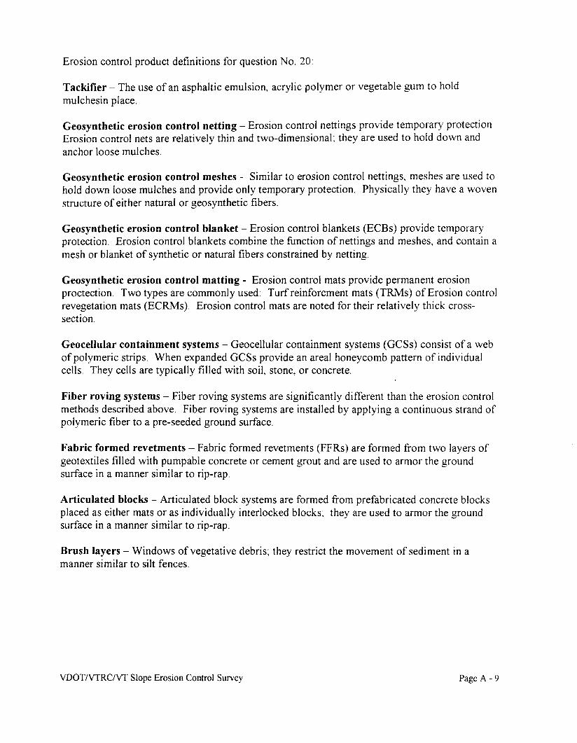
Erosion control product definitions for question No. 20:
Tackifier - The use of an asphaltic emulsion, acrylic polymer or vegetable gum to holdmulchesin place.
Geosynthetic erosion control netting - Erosion control nettings provide temporary protection.Erosion control nets are relatively thin and two-dimensionaL they are used to hold down andanchor loose mulches.
Geosynthetic erosion control meshes - Similar to erosion control nettings, meshes are used tohold down loose mulches and provide only temporary protection. Physically they have a wovenstructure of either natural or geosynthetic fibers.
Geosynthetic erosion control blanket - Erosion control blankets (ECBs) provide temporaryprotection. Erosion control blankets combine the function of nettings and meshes, and contain amesh or blanket of synthetic or natural fibers constrained by netting.
Geosynthetic erosion control matting - Erosion control mats provide permanent erosionproctection. Two types are commonly used: Turfreinforcment mats (TRMs) of Erosion controlrevegetation mats (ECRMs). Erosion control mats are noted for their relatively thick crosssection.
Geocellular containment systems - Geocellular containment systems (GCSs) consist of a webof polymeric strips. When expanded GCSs provide an areal honeycomb pattern of individualcells. They cells are typically filled with soil, stone, or concrete.
Fiber roving systems - Fiber roving systems are significantly different than the erosion controlmethods described above. Fiber roving systems are installed by applying a continuous strand ofpolymeric fiber to a pre-seeded ground surface.
Fabric formed revetments - Fabric formed revetments (FFRs) are formed from two layers ofgeotextiles filled with pumpable concrete or cement grout and are used to armor the groundsurface in a manner similar to rip-rap.
Articulated blocks - Articulated block systems are formed from prefabricated concrete blocksplaced as either mats or as individually interlocked blocks: they are used to armor the groundsurface in a manner similar to rip-rap.
Brush layers - Windows of vegetative debris~ they restrict the movement of sediment in amanner similar to silt fences.
VDOT/VTRC/Vf Slope Erosion Control Survey Page A - 9

21. What information and/or design aids would be most helpful for use in designing slopeerosion control measures?
Section 3 - Construction, Maintenance, and Performance
22. How soon after cut slope excavation or fill slope placement are erosion control measuresusually implemented? Please tell us the typical amount of time.
23. Is there a limit on the amount of exposed ground before slope erosion control measures areimplemented? If yes, what is the limit?
VDOT/VTRCIVr Slope Erosion Control Survey Page A - 10

24. How important is the influence of the time of year in the amount of slope erosion thatoccurs?
Very important Important Somewhat important Not important
If you answered "Very important" or "Important," in which season does the most slopeerosion occur and why?
Spring Summer Fall Winter
25. What personnel are involved in construction inspection for slope erosion control measures?
26. Is the effort expended on construction inspection for slope erosion control measuresadequate? How much time should be allotted per acre for construction inspection of erosioncontrol measures?
27. Are all of the slope erosion control measures specified in the contract documents alwaysconstructed?
VDOTIVIRC/Vf Slope Erosion Control Survey Page A - II

28. Are certain specified slope erosion measures routinely altered or deleted during construction"If yes, which ones?
29. Is post-construction inspection of erosion control measures adequate? How often shoulderosion control measures be inspected after construction? How much time (hours/acre/year)should be allotted for post-construction inspection of erosion control measures?
30. Is post-construction maintenance of erosion control measures adequate? How much money($/year/acre) should be allotted for post-construction maintenance of erosion controlmeasures?
31. Under what conditions do slope erosion control measures fail?
VDOTIVTRCIVf Slope Erosion Control Survey Page A - 12

Section 4 - Concluding Question
32. Please provide any other comments you would like to make about slope erosion:
Thank you very much for your cooperation!
VDOTIVTRC/VT Slope Erosion Control Survey Page A - 13

AppendixB
VDOT Guidance for Erosion Control Blankets and Mats
Erosion Protection for Soil Slopesalong Virginia's Highways

Appendix B.l
Listing of Approved Products: EC-2 and EC-3
Erosion Protection for Soil Slopesalong Virginia's Highways
t. '
VIRGINIA DEPARTMENT OF TRANSPORTATIONSTD. EC-2 EROSION CONTROL BLANKETS
APPROVED LIST (REV. 3n/97)
(VELOCITY 2.5 - 4.0 f.p.s.)
CurlexAmericam Excelsior CompanyP.D.Box 5067 ..Arlington, Tx.76011
Dekowe 700Dekowe 900Belton IndustriesHambry RoadBelton, South Carolina 29627
Poplar Excelsior Stitched BlanketWinters St'd. & H. V. Straw BlanketsWinters Excelsior Company, Inc.P. O. Box 39, Hwy 21McWilliams, Alabama 36753
Jute MeshLudlow Manufacturing & Sales Co.Needham Heights 94, Ma.
Ridgegrow Excel. Eros. Cant. BlanketRidgegrow Wood ProductsP.D.Box 812Somerset, Ky. 42501
North American Green 5-75North American Green 5C-150North American Green C-125North American Green, Inc.Evansville, Indiana 47711
Soil Saver Heavy Jute MeshJim Walls CompanyCommerce Plaza, Suite 10912820 Hillcrest RoadDallas, Texas 75230
Jute MeshB & M Packaging Co., Inc.11515 Granite Street 28273P.D.Box 411007Charlotte, N.C.28241-1007
Anti-Wash/GeojuteBelton Industries8613 Roswell Road, Suite 200Atlanta, Ga. 30350
X-Gel Permamat 100,X-Gel Regular, and X-Gel SuperiorPPS Packaging Co.P.D.Box 427Fowler, CA. 93625-0427
Jute MeshBemis Brothers Bag CompanySt. Louis, Mo.
Jute MeshBelting Bagging CompanyBelton, South Carolina
JMD Jute MeshJMD Manufacturing5401 Progress Blvd.Bethel Park, PA. 15102
Verdyol Standard ERO-MATVerdyol High Vel. ERO-MATVerdyol Excelsior StandardVerdyol Excelsior High Vel.Verdyol Xtra StandardVerdyol Xtra High VelocityVerdyol Alabama, Inc.P.D.Box 605105 Miles Pkwy.Pelt City, AL. 35125
BonTerra S-1, 5-2, CS-2, &C-2BonTerra AmencaP. O. Box 9485Moscow, efdaho 83843
~
EarthlockECS Products, Inc.9015 Energy LaneNorthport, Alabama 35406

Standard Excelsior BlanketStandard Straw MatHigh Velocity Excelsior BlanketHigh Velocity Straw MatErosion Control Systems, Inc.9015 Energy LaneNorthport, Alabama 35476(205)333-3080
Greenfix WS052 Straw MatGreenfix AmericaP. O. Box 23310Santa barbara, California 93121(619)344-6700
BioD-Mat 70 & BioD Mat 90Rolanka International, Inc.6476 Mill CourtMorrows, Georgia 30260(404)961-0331
§244.02 (k)(2) Soil retention mats shall consist of a machine-produced mat of wood fibers, woodexcelsior, or manmade fiber that shall intertwine or interlock. Matting shall be nontoxic tovegetation and germination of seed and shall not be injurious to the unprotected skin of thehuman body.
Mats shall be of consistent thickness, with fiber evenly distributed over its entire area, andcovered on the top and bottom side with netting having a high web strength or covered on the topside with netting having a high web strength and machine sown on maximum 5.08 cm centersalong the longitudinal axis of the material. Netting shalf be entwined with the mat for maximumstrength and ease of handling.
2

STD. EC-3 TYPE A AND TYPE B SOIL STABILIZATION MATSAPPROVED LIST (REV. 7120/98)
TYPE A MATS(Velocity 4.0 - 7.0 f.p.s.)
Enkamat Earthlock, 7005, and 7010Erosion Control Systems9015 Energy Lane •Northport,AI. 35476(800)942-1986 FAX (205)333-3090
Miramat Regular (18 Qz.lsq.yd.)TC Mirafi365 S. Holland DrivePendergrass, Georgia 30567(800)685-9990 e589 FAX (706)693-4400
Landlok 1050 North American Green C350Synthetic Industries North American Green4019 Industry Drive 14649 Highway 41 NorthChattanooga, Tennessee 37416 Evansville, Indiana 47711(800)621-0444 FAX (423)499-0753 (812)867-6632
"l--{f'f:r B(Velocity 7.0 - 10.0 f.p.s.)
Bon Terra America SFBBon Terra America Inc.P.D.Box 9485Moscow, Idaho 83843(208)882-2512
Enkamat 7012,7020,7210, & 7220Erosion Control Systems9015 Energy LaneNorthport,AL 35476(800)942-1986, FAX (205)333-3090
Miramat Heavyweight (24 oz.lsq.yd.)Mirafi TM 8TC Mirafi365 S. Holland DrivePendergrass, Georgia 30567(800)685-9990 e589 FAX (706)693-4400
North American Green P-300, P300PNorth American Green14649 Highway 41 NorthEvansville, Indiana 47711(812)867-6632
TerraGuard 44P &45PWEBTEC, Inc.P. O. Box 240302Charoltte, NC 28224-0302(800)438-0027, FAX (704)394-7946
Tensar TB1000 & TM3000Tensar Earth Technologies5775-8 Glenridge DriveLakeside Center, Suite 450Atlanta, Georiga 30328-5363(800)292-4459, FAX (404)705-9650
Landlok 435,450,460, & 1060Synthetic Industries4019 Industry DriveChattanooga, Tennessee 37416(800)621-0444, FAX (423)499-0753
PEC-MATGreenstreak, Inc.3400 Tree Court Ind. Blvd.St. Louis, Missouri 63122(800)325-9504, FAX (314)225-9854
* Mats listed in the Type B category may be substituted for the Type Amaterial at no additional cost the VDOT.

STD. EC-3 TYPE C SOIL STABILIZATION MATSAPPROVED LIST (REV. 7/20/98)
(Slopes 3: 1 and flatter)
Enkamat Earthlock, 7005, and 7010Erosion Control Systems9015 Energy LaneNorthport,AL 35476(800)942-1986, FAX (205)333-3090
Landlok 1050Synthetic Industries4019lndust~DMve
Chattanooga, Tennessee 37416(800)621-0444, FAX (423)499-0753
Miramat Regular (18 oz.lsq.yd.)TC Mirafi365 S. Holland DrivePendergrass, Georgia 30567(800)685-9990 e589, FAX (706)693-4400
North American Green C350North American Green14649 Highway 41 NorthEvansville, Indiana 47711(812)867-6632
* Mats listed in the Type 8 category may be substituted for the Type Amaterial at no additional cost the VDOT.
TYPE C MATS(Slopes steeper than 3:1)
Enkamat SErosion Control Systems9015 Energy LaneNorthport,AL 35476(800)942-1986, FAX (205)333-3090
Pyramat 4700Synthetic Industries4019 Indust~ DriveChattanooga, Tennessee 37416(800)621-0444, FAX (423)499-0753
2

Appendix B.2
Instructional and Informational Memorandumfor the use ofEC-3
Erosion Protection for Soil Slopesalong Virginia's Highways

s ___
VIRGINIA DEPARTMENT OF TRANSPORTATION
LOCATION AND DESIGN DIVISIOr·~
INSTRUCTIONAL & INFORMATIONAL MEMORANDUM
GENERAL SUBJECT:
SOIL STABILIZATION MAT
SPECIFIC SUBJECT:
STANDARD EC-3
SIGNATURE:
CURRENT REVISION
NUMBER:LD-96 (D) 166.3
DATE:March 22, 1996
SUPERSEDES:LO-94 (D) 166.2
Shaded.
standard EC-3 Soil stabiiliiit:lon-Mat---'$lope"-!nstallatlonSheet 2 of 2 in the 1994 Metric Road and Bridae Standardsand the 1993 Imperial 8009. and Bridge ptandarg§ is void.
Standard EC-3, Sh.et 2 of 2 ~ is replaced .by an InsertableSheet for Standard EC"'3, ~. e, Soil stabilization Mat~o~ ,~~~...~ slo~ ~~ili~ati~~. '.. .
A Pay' Item has"'been added for St.andard EC-3~'~. c, SoilStabilization Mat.' .
EFFECTIVE DATE
Xhe.se·~ instruCtions..··· are effeCtive-'~.', on' all projectsscheduled ..for tbe AU<JUst 1996 advertisement and all~.~~9u~~~'. ~~~j~~~~~~~ ' . ... ~ ~...... ..
POLICY
Ditches
Geotextile materials designated as standard EC-3 (Type Aand B) Soil Stabilization Mat are used for protectivelinings in ditches.

LD·96 (D) 166.3She.t 2 of 4
Standard EC-3 Soil Stabilization Mat is intended to beused as a protective ditch lining material to be appliedwhen the design velocity exceeds the allowable velocityfor Standard EC-2 (i.e., jute mesh).
When the design velocity exceeds the allowable velocityfor Standard EC-3, a paved (or riprap) lining will berequired.
Slopes
The Standard EC-3 (Type C) Soil Stabilization Mat may beused as a protective slope lining for dry cut or fillslopes and wet cut slopes to stabilize the slope on whichvegetation is being established. (See Road and BridgeStandards)
TYPES AND APPLICATION
Ditches
Type A is to be employed where the design (2 year)velocity in the ditch is within the range of 1.2 to 2.1meters per second (m.p.s.) (4 to 7 f.p.s.)
Type B is to be employed where the design velocity iswithin the range of 2.1 to 3.0 m.p.s. (7 to 10 f.p.s.)
A Manning' s "n" value of o. 05 should be used withstandard EC-3.
Typically, the use of Standard EC-3 Type A should beginat the point where flow velocity exceeds 1.2 m.p.s. (4f.p.s.) (velocity is assumed to be for flow in an EC-2lined channel) and continue changing to EC-3, Type B atthe appropriate point, until the design velocity exceeds3.0 m.p.s. (10 f.p.s.) or until such point as the use ofa ditch lining can be discontinued.
Experience has shown that the installation of thismaterial is particularly critical. It must be installedin strict accordance with the standard drawings andmanufacturer's specifications.

LD-96 (0) , 66.3Shelt 3 ~ ~
It is requested that standard EC-3 (Type A and B)installations be monitored very closely to determine thevalidity of the present design criteria. It isrecommended that the District Drainage Engineer, incooperation with appropriate District Environmentaland/or Maintenance personnel, visit these installations,particularly after significant or intense rainfallevents, and prepare a report of their observations whichwould then be submitted to the Central Office HydraulicsSection on a regular basis until further notice.
Slopes
Locations are to be recommended by the DistrictEnvironmental and/or Materials sections during plandevelopment.
Standard EC-3 Type C is to be installed in accordancewith the standard drawing and the manufacturer'sspecifications.
PAY ITEMS AND SUMMARIZATION
The following i~ems are -to be sUmmarized, when applicable, in theErosion & Sediment Control Summary on the Roadside DevelopmentSheet:
ITEM UNIT ITEM CODE
Soil Stabilization MatEC-3, Type A m2 (S.Y.) 27325
Soil Stabilization MatEC-3, Type B m2 (S.Y.) 27326
Soil Stabilization-Mat-m2
~=~~ .. ~e.~ (5. Y. ) 27327
INSERTABLE SHEET
The following ~nsertable Sheet (Metric and Imperial) will beavailable in the CADD Insertable Sheet Directory after March 25,1996. .
SOil· Stabilization Mat - Slope Installation Type C tDrawing No. A 107.

.()........
i..
U 1 ..; Ii l t I1 ~ l 1J w 4 ~
~ ! i tIe i iIt iii1.1 I " ,il J I
!~ i. 1 1I· "'.,. J I ~
1t IiiiJ J ~~ j1
.. :1 ·Ie)~ 11o !, I -. IIz .....s Jl -.
I.
~I Ifw .,C) j.
~:
it'::l
wCl0..JV')
>-Q:0
~z~..J
W0..0 ....JV" I
0•
I'I
i
NOTE:~ THIS 015 A SAMPlE JNSERTABLE ,SHEET.v. FOR A.0 MORELEGIBLEAND CURRENTVERStOtt ACCESS
THE CAnD INSERTABlE SHEET DfRECTORY. ,,- .,....... v .• :.~.~ 1(,-''''~....'\. " ...., ~.~ )'wo ••A.~'A ••,'" ." tClIC>."~""""',.>It"'.·•• .. , ..'\0". " .,
L.[).96 CD) '66.3Sheet ~ of 4
i

Appendix C
Form for Collecting Information aboutSlope Erosion Control
Erosion Protection for Soil Slopesalong Virginia's Highways

.----
Desi~n dataMethod used: principle based I USLE I decision analysis I field engineering
other (describe): IIJrotection required or
other data:I
i
sediment at toe
Shade or sun:
bare ground
l -----L.--1
Erosion protection providedTemporary or permanent: I
Type(s) of protection provided: Biotechnical Armoring Improved practices
Additional description(s): mulches rip-rap silt fencestackifiers gabions hay balesnettings articulated blocks brush layersmeshes fabric revetments benches
blankets (EC-2) sediment trapsmats (EC-3) Ifused is there a check dams
geocelluar system filter layer beneath: sediment basinsfiber roving system yes no sediment ponds
live plantings
List manufacturers and brands:
Type(s) of vegetation:}
Perforlnance IContractor name: I Date constructed: I
Construction quality: outstanding Iexcellent I good I poor I other ISignificant rainfall:
Describe performance:(use back of form if additional
space is required)