river bank erosion and boat wakes along the …€¦ · wakes along the lower shuswap river,...
TRANSCRIPT
RIVER BANK EROSION AND BOAT
WAKES ALONG THE LOWER SHUSWAP
RIVER, BRITISH COLUMBIA
FINAL PROJECT REPORT
submitted to
Regional District of North Okanagan
Fisheries and Oceans Canada
August, 2013
Larissa Laderoute & Bernard Bauer
University of British Columbia Okanagan
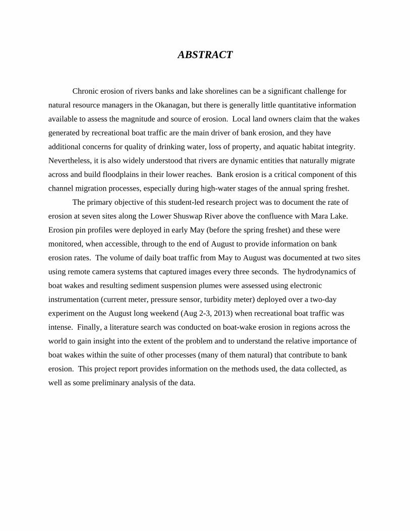
ABSTRACT
Chronic erosion of rivers banks and lake shorelines can be a significant challenge for
natural resource managers in the Okanagan, but there is generally little quantitative information
available to assess the magnitude and source of erosion. Local land owners claim that the wakes
generated by recreational boat traffic are the main driver of bank erosion, and they have
additional concerns for quality of drinking water, loss of property, and aquatic habitat integrity.
Nevertheless, it is also widely understood that rivers are dynamic entities that naturally migrate
across and build floodplains in their lower reaches. Bank erosion is a critical component of this
channel migration processes, especially during high-water stages of the annual spring freshet.
The primary objective of this student-led research project was to document the rate of
erosion at seven sites along the Lower Shuswap River above the confluence with Mara Lake.
Erosion pin profiles were deployed in early May (before the spring freshet) and these were
monitored, when accessible, through to the end of August to provide information on bank
erosion rates. The volume of daily boat traffic from May to August was documented at two sites
using remote camera systems that captured images every three seconds. The hydrodynamics of
boat wakes and resulting sediment suspension plumes were assessed using electronic
instrumentation (current meter, pressure sensor, turbidity meter) deployed over a two-day
experiment on the August long weekend (Aug 2-3, 2013) when recreational boat traffic was
intense. Finally, a literature search was conducted on boat-wake erosion in regions across the
world to gain insight into the extent of the problem and to understand the relative importance of
boat wakes within the suite of other processes (many of them natural) that contribute to bank
erosion. This project report provides information on the methods used, the data collected, as
well as some preliminary analysis of the data.

ACKNOWLEDGEMENTS
The research for this project could not have taken place without the co-operation and
permission of the individuals who graciously provided access to their properties and who
generously shared their insights and opinions about bank erosion and other issues of relevance
and concern. Their knowledge was critical to a comprehensive understanding of the scope of the
problem and in establishing the project foundations. In this regard, special thanks are extended
to Hermann and Louise Bruns (Wild Flight Farm), Corinne De Ruiter (Springbend Farms), Paul
and Ginny Cox, Lori and Leo Konge (Viking Farms), Bob Harding (Fisheries and Oceans
Canada), Anna Page and Laura Frank (North Okanagan Regional District), as well as Jean
Clark and Jess Washtock (Lower Shuswap River Stewardship Society). Financial support was
provided through the Regional District of North Okanagan, Fisheries and Oceans Canada, and
an internal UBC Okanagan grant provided through the Office of the Dean of the Barber School
of Arts & Sciences.

CONTENTS
CHAPTER 1 Introduction
Pages 1-2
CHAPTER 2 Literature Review
Pages 3-20
CHAPTER 3 Methods
Pages 21-32
CHAPTER 4 Results
Pages 33-63
CHAPTER 5 Conclusion Pages 64-66
CHAPTER 6 Bibliography Pages 67-72
1
1
INTRODUCTION
The Lower Shuswap River flows from Mabel Lake westward to Enderby, BC and then
northward in to the southern end of Mara Lake. The lowermost portion is heavily used for
fishing, birding, kayaking, boating, and waters sports while also providing important ecosystem
habitat. The quality of the water that drains into Mara Lake is especially important for the
lakeside residents and for the town of Sicamous because this is the primary source of domestic
water supply. The river and lake margins are also important for the agricultural activities they
sustain and the extensive infrastructure (e.g. houses, resorts, roads, power lines) that is located
there. Maintaining the integrity of the river banks by preventing erosion is critically important.
Unfortunately, there are many locations that are chronically eroding (Hawes et al., 2011)
although there are few data on the rates of erosion, the extent of damage, and the cumulative
impact of bank erosion on water quality and habitat loss. Anecdotal opinion of local
stakeholders suggests that recent increases in recreational boat traffic may be a factor because of
the erosive nature of boat wakes as they impinge on the shore. In the absence of qualitative data
on the impact of boat wakes, relative to other sources of erosion, it becomes difficult to manage
and mitigate the problem.
The Shuswap River provides habitat for a large variety of aquatic organisms, and there is
a significant salmon run that makes its way through Mara and Mabel Lakes and into the Middle
Shuswap River all the way to Wilsey Dam (near Lumby). Progressive erosion of river banks and
lake margins has the potential to degrade the quality of habitat for these organisms. Not only is
this significant natural capital, but there is important cultural relevance to First Nations. The
physical environment of the river changes drastically when exposed to erosion. This is also of
concern for individuals who own property along the river. The structural soundness of homes
could become weakened as erosion undermines the stability of the ground that supports the
foundations. Businesses along the waterfront may be similarly at risk. Further damage could be
experienced along Highway 97A and other roads with sections that run along the Shuswap River
and Mara Lake or have bridge crossings. Ultimately there will be high costs associated with
2
repairing the damage caused by erosion or in mitigating the effects through ongoing maintenance
programs.
The primary objective of the project was to monitor and document the rate of bank
erosion at a small sample of chronically eroding ‘hot spots’ that were identified by project
personnel with input from local landowners and in consultation with the North Okanagan
Regional District (NORD) and Fisheries and Oceans Canada (DFO). A secondary objective was
to monitor the extent of boat traffic with a view to assessing the potential impact of boat wakes
on bank erosion. In order to accomplish these objectives, the study adopted a multi-method
approach that yielded the essential information needed to quantify the processes that are central
to the bank erosion problem. Specifically, measurements were taken of: (a) bank erosion rates at
a network of sites using erosion pins installed in the banks; (b) the volume of daily boat traffic at
two strategic sites using a remotely located camera; and (c) the detailed fluid mechanics of
individual boat wakes and the resultant sediment suspension plumes using a range of
submersible electronic instruments.
Data collected during the sediment transport experiments were analysed to provide
estimates of wave height, wave energy, bottom velocities, and turbidity (suspended sediment
concentration) in association with single and multiple boat passages. A photographic record of
these boat passages was also made in order to estimate boat length and speed in crude categories.
The long-term boat traffic survey using remotely triggered cameras provided a means by which
to connect the hydrodynamic data to bank erosion potential, and thence to actual erosion pin
data. This report provides details on the experimental methods as well as a summary of the data
that were collected during the 4-month study (May to August, 2013). Data disks are available
upon request.
3
2
LITERATURE REVIEW
Introduction
Wave energy generated from the passage of boats is a major concern as it increases the
potential for erosion of river banks, shorelines, and levees (Bauer et al., 2002). A significant
effort has been made by many scientists to better understand the process of boat wake-induced
erosion in many parts of the world such as the California Delta (Bauer et al., 2002), Marlborough
Sounds in New Zealand (Parnell, McDonald, & Burke, 2007), the Kenai River in Alaska (Dorava
& Moore, 1997) and the Illinois and Mississippi River systems (Bhowmik, 1981). Erosion is a
concern for reasons relating to aquatic habitat, water quality, and loss of property as well as
disruption of natural sedimentation processes in rivers and lakes.
Waterways of all kinds are beneficial to society in many different ways. Not only do
they provide recreational opportunities, but they also effectively discharge floodwater, dilute
effluents, support the fishing industry, carry freight, provide transportation, and are often the
main source of drinking water for nearby communities. Waterways are also very important
ecologically, as they support a very rich and diverse community of plants and animals (Bonham,
1983). It is important for society to take responsibility to preserve our rivers, streams, lakes, and
oceans for the ecological resources they provide.
There is a broad range of terminology that describes the many watercrafts that travel
across our waterways. Motorized watercrafts include both boats and personal water crafts
(PWC). PWCs are recreational watercrafts where the passengers stand or sit on the watercraft
rather than inside the hull. These PWCs are commonly referred to as a ‘Jet Ski’ or 'Sea-Doo'
(where the latter is a company name covered by copyright). The use of PWCs has allowed for
recreational traffic on small waterways and closer to beaches where motorized traffic was
previously nominal (Beachler and Hill, 2003). The range of boats includes such common names
as power boat, speed boat, ski boat, wake boat, aluminum fishing boat, bass boat, jet boat,
pontoon boat, runabout and cabin cruiser, among others. It is well known that the shape of the
hull and the speed of the watercraft are the two most critical factors in determining wake size.
For example, wake boats are specifically designed to create large wake waves so that wake
4
boarders are able to surf behind the boat and perform tricks involving acrobatic aerial
manoeuvres. They have internal bladders that can be filled with water in order to yield
maximum water displacement by the submerged portion of the hull. They are thus of special
interest to the issue of bank erosion along lakes and rivers. However, this does not mean that
wake boats are the only water craft that create large wakes. PWCs and runabouts have a smaller
size than most other watercrafts, yet they both have the potential to create wakes of similar size
and power of a wake boat (Baldwin, 2008) depending on how they are used. It is somewhat
counter-intuitive to recognize that when boats travel very quickly, above planing speed, they
often produce relatively small wake waves, and this is certainly true of most PWCs, which are
designed for high speed. Boats with large hull displacements travelling just below planing speed
typically create the largest wakes.
In many parts of the world, large scale vessels such as ships and ferries are the source of
boat wakes in semi-enclosed seas and sheltered waterways. Boat wakes from ferries become
increasingly serious when operated in shallow waters near the coats. Ferry traffic has been
identified as the main factor resulting in erosion on shorelines located in Denmark, United
Kingdom, Ireland, the United States and New Zealand (Kirkegaard, Kofoed-Hansen, & Elfrink,
1998). In earlier decades, the wakes from large vessels were considered negligible or
acceptable; however, after the introduction of high-speed craft (HSC) that were capable of
carrying vehicles and passengers in 1980, the effects became noticeable across the world. The
adverse erosional effects of HSCs such as large catamarans that are used as industrial ferries are
mainly due to their high speeds and large size producing longer wakes than conventional ships
(Parnell, McDonald, & Burke, 2007).
The core recreational boating industry in Canada is primarily of manufacturers, stores,
marinas, repair and maintenance shops, schools and boat clubs, and other related companies.
The industry itself consists of approximately 4,400 companies that service nearly 4.3 million
boats that operate in Canada. In 2012, Canada’s boating industry had an economic impact of $5
billion and generated revenue of approximately $8.9 billion. The boating industry provided
67,000 jobs in the country. Annual taxes and subsidies from the core industry contributed $774
million to Canada’s economy (NMMA Canada, 2013). Over the last 25 years boating
registrations have significantly increased, and the size of the average boat has become
significantly larger (Beachler and Hill, 2003). Larger boats require larger engines (Asplund,
5
2000), and the National Marine Manufacturer’s Association (NMMA) has reported that the
average horsepower of boat motors has increased from 65 in1985 to 86 in 2000 (Beachler and
Hill, 2003). In the United States, Florida has the largest number of registered boats in the
conterminous states. In 2007, 1.027 million boats were registered in Florida with 97% being
used for recreational purposes (Swett, Listowski, Fry, Boutelle, and Fann 2009).
Boating is among the most popular activities along waterways across the world. In many
places it is also the largest industry. In addition to having the largest number of registered boats,
the marine industry and associated sectors in Florida had an economic impact of $18.4 million
and has created employment for 220,000 people. It is estimated that approximately 350,000
unregistered vessels are operated on state waters in the same year. The number of registered
boats recently exceeded the state population. Between the years 2000 and 2006, the state
population increased by 15% and boat registrations increased by 16%. If the trend continues,
by 2016 the estimated boat registration will be 1.38 million (Swett et al., 2009).
Understanding the causes of erosional shoreline changes is difficult as there are many
factors to consider, especially in human-modified environments (Houser, 2010). A limited
amount of baseline data is available to make comparisons between shoreline changes before and
after the introduction of motorized watercrafts. However, geomorphologists are making large
advances in collecting data and generating a better understanding between natural and human
influenced shoreline erosion. It is sometimes difficult to gain knowledge of boat wake-induced
erosion as a large portion of the literature concerning wake effects is found in unpublished
reports (Aage et al., 2003) such as environmental impact assessments for private corporations
and government use.
Previous Studies on Mitigating Boat-Wake Erosion
In the past 20-30 years, a large number of studies have been conducted on the impact of
recreational and commercial boating traffic on bank erosion along rivers, lakes, and large
embayments. There is as yet no consensus regarding the precise amount of erosion that can be
caused by boats relative to natural processes involving currents, wind waves, and tidal
fluctuations, but it is increasingly clear that boats do indeed play a role in acceleration erosion
rates.
6
The lower Gordon River in Tasmania is a river that is being severely impacted by boat
wake erosion and has been studied for quite some time (e.g., Bradbury, Cullen, Dixon, &
Pemberton, 1995 and Bradbury, 2005). This waterway is popularly used for commercial cruise
vessels and has a long history of regulations dating back to 1985. The current regulations permit
a maximum wave height of only 0.075 m (i.e., 3 inches), which is extraordinarily small for any
vessel passage. However, monitoring and experimental testing has demonstrated that this
regulation is not very effective against erosion. This is due to recreational traffic not being
subject to the regulation even though there is a disproportionally large impact. A report
published by Bradbury (2005) uses geomorphic evidence to create guidelines and
recommendations for cruise vessels to reduce the impacts of vessel wakes on the river. This
proposal includes specific licensing for cruise vessels and revision of current speed limits. The
proposal recommends that all non-commercial vessels adhere to a 9 kmh-1 maximum speed limit.
Continued monitoring is also recommended to observe any critical changes in the river system
and allow for adaptive management.
It was believed that boat passages were causing significant amounts of erosion along the
archipelagos between Montréal and Sorel. In an attempt to reduce the rate of erosion, the
shipping industry introduced a voluntary speed limit in the fall of 2000. Although it is difficult
to estimate the amount of erosion that naturally occurred before the increased use of ships and
boats, the data collected three years after the introduction of voluntary speed limit demonstrates
that shoreline recession has decreased by as much as 45% in certain areas. As a result, an
agreement has been made between the shipping industry and the Canadian Wildlife Service to
maintain the speed reduction in specific areas identified by the Canadian Wildlife Service
(Fisheries and Oceans Canada, n.d.).
The Kenai River in Alaska is economically important for the salmon industry as it
generates $78 million annually in direct benefits. The river is under a strict watch by resource
management agencies due to a rising concern that increased sedimentation and loss of streamside
habitat is occurring as a result of accelerated erosion from boat wakes. The boating period
begins in early May and begins to decline in early August with the peak boating period occurring
in mid-July (Dorava and Moore, 1997). The peak coincides closely with the annual return of
salmon return and also with measured peaks of bank erosion. More than 20,100 boats were
observed at a specific site along the river between July 12 and September 10, 1996. At this
7
meander bend site, a loss of nearly 1.14 m of bank width was observed during the observation
period. Previous to the study, large scoured embayments were documented, indicating that boat
wake erosion has most likely been a problem in the area for a long period of time (Dorava and
Moore, 1997). However, it seems that the amount of boat wake-induced erosion occurring on the
river banks is dependent on water flows. If the peak boating period occurs during low flows, the
energy from boat wakes will be expended across the cobble bars at the margins of the river,
thereby protecting the banks from significant erosion. However, if the peak boating period
occurs during somewhat higher flows, the energy from boat wakes will be transferred directly to
the banks above the cobble bars. Thus, it appears that the erosive impact of boat traffic is partly
mitigated by low flow conditions during the year (Maynord et al., 2008).
In response to growing conflict concerning the protection of the river in the 1980s,
actions were taken to protect the fish habitat from the direct and indirect impact of boat traffic.
Solutions included restricting fishing on certain days during peak boating periods, limiting the
horsepower of boats, enforcing speed limits, and completely banning power boats along certain
reaches of the river. It is believed that the regulations achieved the goal of reducing these
impacts; however, it is difficult to quantify the reduction (Maynord et al., 2008).
The Sacramento-San Joaquin River Delta in California has experienced significant
amounts of erosion of unprotected levee banks by boat traffic. By being unprotected and in a
'natural' state, the banks have limited structural integrity and are often susceptible to failure. In
response to the chronic erosion, organic restoration structures, such as brush bundles, have been
installed to reduce the impact of boat wakes. Ellis et al., (2002) used pressure sensors to assess
the ability of restoration structures to reduce energy from boat wakes and to determine if energy
reduction is dependent on water depth because the site was influenced by tidal fluctuations. The
study showed that these organic reduced up to 60% of the incident wave energy at certain times
of the tidal cycle. The structures effectively dissipate energy from boat wakes while also trapping
suspended sediment behind them, which contributes to sedimentation and reoccupation by
riparian vegetation.
Other attempts to reduce erosion along the Sacramento River system include the addition
of groynes. Groynes are rigid structures that extent from the shore with a purpose of interrupting
water flow. They are widely used on ocean beaches, and they have been found to significantly
reduce rates of erosion and limit the movement of sediment (Ercan and Younis, 2009). Groynes
8
are commonly found in places such as the Waal River in the Netherlands, Bournemouth in
England, and Crescent Beach in Canada Groynes are used in both coastal and river systems, but
their design is distinct for each location. River groynes are commonly used to prevent bridge
scouring. However, groynes have a large disadvantage as they cause significant problems
downstream from their location. An investigation as to the effectiveness of the groynes on the
Sacramento River was conducted by Ercan and Younis (2009), and they concluded that without
the groynes the maximum erosion rate was estimated to be 5.6 m per year which was reduced to
4.7 m per year with the installation of four groynes.
In the state of Louisiana, USA, the local coastal communities have built intertidal
sediment fences that are modeled after similar fences used in the Netherlands, which enhance
sediment deposition and revegetation along the riverbanks and mudflats. They are made out of
recycled Christmas trees and have been manufactured by locals in Louisiana since 1987. The
communities have seen a major success with this method as well as significant community buy-
in and support. The construction of Christmas tree fences has become standardized through the
Louisiana Department of Natural Resources (LDNR), which provides funding to local
communities for the project. Some communities are seeing results from the installation of the
fences such as colonization of wetland species. However, some communities have not been as
successful with the project. After rigorous work conducted by Boumans et al., (1997), they
found that Christmas tree fences effectively dissipate wave energy, reduce sediment
resuspension, enhance deposition, and cause consolidation of surface sediments. In addition,
predominant erosion was not observed at any of the study locations even in the midst of severe
storms, including Hurricane Andrew in August 1992.
Publicly addressing and communicating the issues concerning boat wakes is another form
of mitigation that may be useful in situations where recreational boat traffic is the main source of
boat wakes. This may come in forms such as pamphlets, factsheets, warnings, notices, and other
advertisements like commercials. The public is unlikely to voluntarily take precautions to reduce
the impacts of their boat wakes if they are unaware they are adding to the problem. Both the
Green Blue (2008) and the Pike Lake Community Association (2013) have published pamphlets
or factsheets in an attempt to make the public aware of their contribution to the problem and how
the public can reduce their impacts.

9
Natural Dynamics of Rivers
Humans have always been interested in the dynamics of free-flowing water, and at the
same time, are constantly attempting to restrain the natural flow of rivers. However, rivers are
naturally meandering. They have complex feedback loops that yield complex adjustments. The
channel is at a constant state of adjustment between erosion and deposition along the length of
the channel. Erosion typically occurs on the outside of a meander bend where the current is the
largest, while deposition occurs on the inside of a meander-bend. As erosion occurs, the eroded
material typically contributes to deposition downstream thereby sustaining a continuous series of
interconnections along the longitudinal profile of the river system. In the lower reaches of rivers,
meandering and channel shifting are important processes that are essential to the overall health of
the fluvial ecosystem. The lateral and downstream migration of river channels can be observed
and measured over periods of years, and this reality makes it particularly difficult to design and
install structures in the river that are intended to be 'permanent' from society's perspective.
It is important to appreciate that even if boat traffic were to be eliminated completely
from a river system, erosion by natural factors would still proceed (Maynord et al., 2008). Thus,
it is critical to understand the natural dynamics of rivers as the natural back-drop against which
the impact of boating traffic can be assessed. Changes in channel position are inevitable, along
with recurring flooding events, so river managers have to plan accordingly to allow the river
sufficient space to meander naturally instead of creating bank stabilization techniques intended to
restrict the course of the river (Baldwin, 2008). In this context, the appropriate question is not
whether boat wakes cause erosion, because they most certainly do to some extent. Rather the
more significant question deals with the degree to which boat-wake induced erosion might be
accelerating or substantively modifying the natural tendency for rivers to erode and rebuild their
banks as part of the meandering process.
Basic Wave Mechanics
River bank erosion is driven by the energy exerted by the flow on the banks. In most
rivers, the source of energy is the downstream flow of water, which creates near-bank currents
that apply shear stresses on the bank materials. If the bank materials (gravel, sand, silt, clay) are
10
able to resist this shear stress, then there is no bank erosion. However, when the shear stress
exceeds the threshold for entrainment of the bank materials, erosion occurs. The same situation
applies to waves that impinge on the shoreline regardless of whether their source is from boat
passages, wind forcing, or nearby landslides.
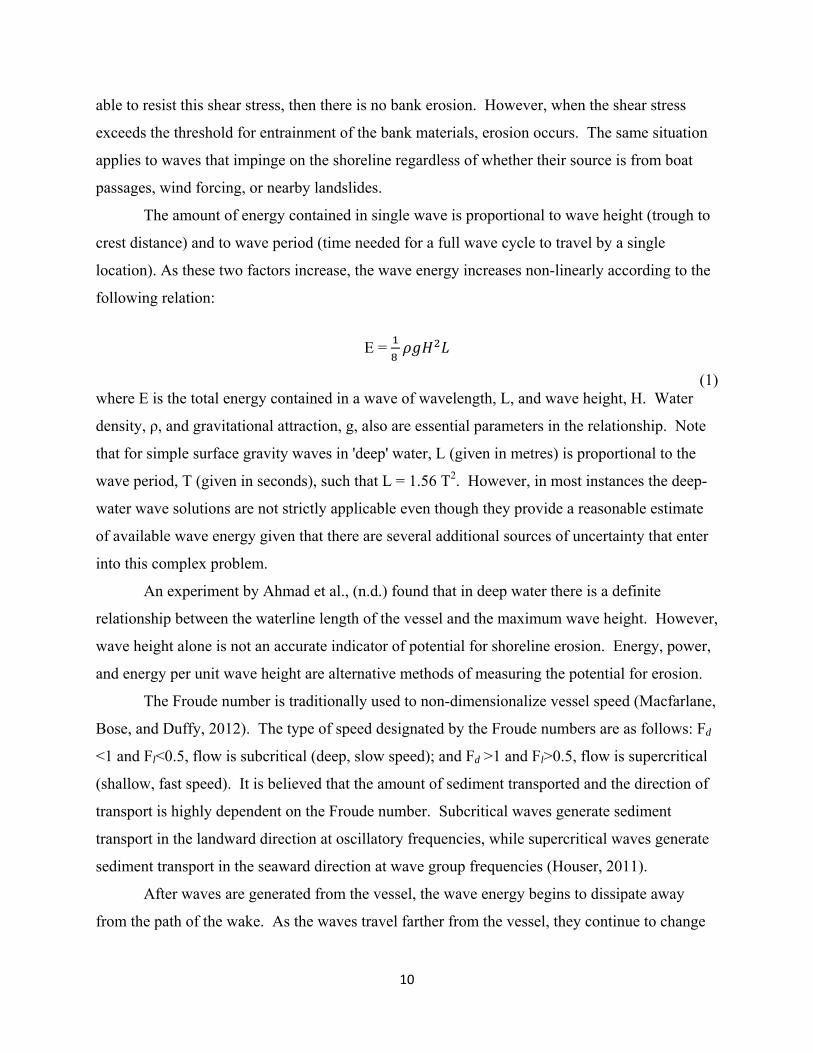
The amount of energy contained in single wave is proportional to wave height (trough to
crest distance) and to wave period (time needed for a full wave cycle to travel by a single
location). As these two factors increase, the wave energy increases non-linearly according to the
following relation:
E =
(1) where E is the total energy contained in a wave of wavelength, L, and wave height, H. Water
density, ρ, and gravitational attraction, g, also are essential parameters in the relationship. Note
that for simple surface gravity waves in 'deep' water, L (given in metres) is proportional to the
wave period, T (given in seconds), such that L = 1.56 T2. However, in most instances the deep-
water wave solutions are not strictly applicable even though they provide a reasonable estimate
of available wave energy given that there are several additional sources of uncertainty that enter
into this complex problem.
An experiment by Ahmad et al., (n.d.) found that in deep water there is a definite
relationship between the waterline length of the vessel and the maximum wave height. However,
wave height alone is not an accurate indicator of potential for shoreline erosion. Energy, power,
and energy per unit wave height are alternative methods of measuring the potential for erosion.
The Froude number is traditionally used to non-dimensionalize vessel speed (Macfarlane,
Bose, and Duffy, 2012). The type of speed designated by the Froude numbers are as follows: Fd
<1 and Fl<0.5, flow is subcritical (deep, slow speed); and Fd >1 and Fl>0.5, flow is supercritical
(shallow, fast speed). It is believed that the amount of sediment transported and the direction of
transport is highly dependent on the Froude number. Subcritical waves generate sediment
transport in the landward direction at oscillatory frequencies, while supercritical waves generate
sediment transport in the seaward direction at wave group frequencies (Houser, 2011).
After waves are generated from the vessel, the wave energy begins to dissipate away
from the path of the wake. As the waves travel farther from the vessel, they continue to change
11
due to dispersion, friction, and gravity. These complex wave transformation processes are
governed by a set of site-specific characteristics such as bathymetry and the angle at which the
waves propagate away from the wake. Waves generated at supercritical speeds tend to have a
small angle of divergence (4-10°), while waves at subcritical speeds propagate at a large angle
(20-30°) (Houser, 2011). As waves reach the shoreline, they will change shape, size, and
direction as a result of refraction, shoaling, and breaking. When the waves come in contact with
the bed and banks, sediment may become detached and transported due to the wave energy.
Transport of the sediment in the direction of the wave occurs due to the orbital motion of waves
(Kirkegaard, Kofoed-Hansen, & Elfrink, 1998). The orbital motion is the motion beneath the
wave. The motion is larger and oblong near the surface and gradually becomes smaller at depth,
which implies that the forces that a wave are able to exert on the bottom are attenuated (i.e.,
reduced) deeper in the water column. Most boat-wake waves generated by recreational boat
traffic are of short period and short wavelength, and these types of waves don't have any impact
in deep water. But as they migrate toward the bank and interact with the sloping bottom, they
can be quite erosive.
There are other factors that contribute to erosion that must also be considered. Natural
forces include the river currents (especially during floods), wind generated waves (especially
during high-wind events and across long or wide fetches of water), and geotechnical processes
that lead to bank slumping events. However, bank characteristics that affect stability such as
vegetation, the height and slope of the banks, stratification, gain texture, and grain size will also
determine the ability of a bank to erode. Characteristics regarding the water body are also
important. Moreover, unless a localized study is carried out, it is unclear whether boat wakes are
a significant contributor to increased erosion of shorelines and river banks (Baldwin, 2008).
Waves generated from boat wakes differ from waves generated by wind for a number of
reasons. Boat waves are highly localized and dissipate in a matter of minutes after the passage of
the boat, while wind waves are ‘spatially homogenous’ and can last tens of minutes to hours or
longer (Sheremet, Gravois, & Tian, 2012). The energy of a wind wave is determined by the force
generated by the wind. As the wind pushes on the water, the force causes displacement on the
water surface, thus forming a wave. These waves are created continually as long as the wind
blows, and when summed across hours and hours they expend a huge amount of energy on the
banks. The energy of a boat wave is contained within a wake packet that usually consists of a
12
few dozen waves that get smaller and smaller through time. The impact of boat-wake waves on
bank erosion is determined by a number of factors, including displacement of the vessel, the
length of the vessel in contact with the water, shape of the hull, and speed. How much energy is
transferred to the shore from a boat wake will depend on the boat’s proximity to shore (Baldwin,
2008) and its direction of travel relative to the bank. Depending on the environment, even small
boats can have a significant effect on bank erosion if the bank materials lack strength and
structural integrity (Parnell, McDonald, & Burke, 2007).
In an attempt to quantify the relationship between bank erosion and boat wakes, Bauer et
al., (2002) developed an analytical method in a well-instrumented experiment on a levee bank on
the Sacramento-San Joaquin River Delta. The experiment used a series of electromagnetic
current meters and optical back-scatterance sensors to measure the dynamics of boat generated
waves and the sediment suspended from a boat passage. They found that close to the shore in
water depths of approximately 0.5 m, sediment suspension was well-correlated to the waves
from the boat wake. This suggests that the near-bottom velocities were adequate enough to
erode the underlying materials, which in that study were cohesive clays and silts. They also
found that sediment was only suspended locally for a short period of time (1-5 minutes), despite
particle settling times on the order of hours, because persistent river currents carried the
suspended sediments downstream. Thus, boat wakes working in combination with river currents
are able to entrain new material from the bank leading to net erosion of the levee banks.
The Oregon State Marine Board (2003) has determined three speed zones for boats and
their effects based on observations (2003). The slowest speed at which a motor boat can operate
is the displacement speed. The wake created at this speed is minimal and the bow of the boat is
down in the water while in operation. As the speed of the boat increases and attempts to get on
plane the boat is in transition speed. This speed creates the largest wake due to the bow rise,
allowing the stern to plow through the water. When the bow drops back down and the stern lifts
out of the water, the boat is at planing speed. At this speed only a small fraction of the hull
contacts the water. The wake generated is larger than that of the displacement speed, but smaller
than wakes generated at the transition speed. Many large craft cannot reach planing speed due to
their design. Avoiding the transition speed as much a possible will aid in reducing erosion
caused by boat wakes. The best way to achieve this is for the operator of the boat to continually
check the wake that the boat is being produced. Other ways to help minimize wake impact on
13
the shoreline include slowing down in advance to reach displacement speed before coming in
close proximity to sensitive areas and shorelines. Arranging passengers evenly along the boat
will also aid in decreasing wake size. Having too many passengers on the bow of the boat will
also increase wake size (Oregon State Marine Board, 2003).
Boat Wake Impacts
Boat wakes have been observed to affect water clarity and quality through shoreline
erosion. Shoreline erosion is the process in which sediment along the shoreline and river banks
becomes detached from the bank and is suspended in the water and transported through currents
and wave energy. Boat wakes also contribute to water clarity problems through mixing and
disturbing the lake or river bottom, especially in shallow water. Water clarity is commonly
measured by turbidity, which is a measure of the concentration of particles in the water or the
ability of light to travel through the water. Water clarity is an important factor in aquatic
ecosystems as it affects many characteristics of aquatic life and is often an indicator of aquatic
health. Water clarity will determine a fish’s ability to find food, control the amount of light
available for water bed plants to grow, affect the dissolved oxygen content, and affect the water
temperature. Reduced water clarity may interfere with the use of shallow water habitat by fish,
as well as, wildlife habitat along the water’s edge. When the suspended sediment caused by
erosion remains suspended along the shoreline for long periods of time, it may result in shading
over small aquatic plants, and can increase nutrient loads for algae growth. Shoreline erosion
can also affect the quality of the water for human consumption as communities receive their
water from streams and lakes (Asplund, 2000). In most cases, rivers and canals are meandering
and significant widening of the waterways is occurring as a result of erosion (Bonham, 1983).
As the banks experience erosion, the vegetation becomes weakened or in some cases, vegetation
is lost due to undercutting of the bank. This is very problematic for property owners. Not only
is their land becoming smaller from erosion, but as the vegetation decreases, the rate of erosion
from boat wakes increases.
The general public is often hyper-sensitive to the passage of fast, noisy boats and to the
boat-wake waves they create. The impacts of large amplitude waves on the shoreline are very
evident to the human eye as clear water turns to a muddy slurry. However, the actual damage to
14
the bank may be minimal as only small amounts of sediment are stripped from the bottom and
put into suspension, and many times these sediments have been resuspended and redeposited in
the same location many times. Moreover, it only takes a small amount of sediment to cloud the
water. It is therefore essential to measure the actual amount of bank erosion in order to
determine precisely what the effect of a single boat passage is. This is an extraordinarily
challenging technical task (Bauer et al., 2002), and the overall impact of a boat passage depends
on a large number of factors including the distribution of wave heights in the wake packet, the
wave period, and the overall duration of the wave event including waves that are reflected from
the bank only to interact with late-arriving waves from the boat. Damage caused by boat wakes
cannot be solely blamed on large vessels (Ahmad, Yusoff, Husain, Wan Nik, and Muzathik, n.d)
because boat size does not determine the number of waves created by a boat. Even small boats
can generate the same number of waves as a large boat (Ahmad et al., n.d.).
Boat wakes can be a leading cause of sediment re-suspension in some systems (Beachler
and Hill, 2003) even if there is little impact on bank erosion. For example, a study conducted by
Yousef et al., (1980) found increases in nutrient levels from the re-suspended sediment caused by
boat wakes in Florida lakes. Hamill et al., (1999) have also studied the scour patterns that are
created as a result of displacement vessel in shallow water. Resuspension and stirring of bottom
sediments has been found to begin occurring depths shallower than about 3 meters. However, at
depths of approximately 2.2 meters or less resuspension occurs much more significantly
(Beachler and Hill, 2003). Waves generated from boat traffic have the ability to suspend
sediment for long periods of time even after the wave group has passed and be transported
downstream (Houser, 2011).
Many biologists and ecologists are concerned with the impact of boat wakes as they may
have an enormous effect on the mortality of salmon eggs. The forces and shear stresses that
occur as boat wakes travel over the eggs have been observed to cause significant harm to the
eggs (Beachler and Hill, 2003). Scientists have also demonstrated that aquatic organisms are
affected by the sediment that is re-suspended during a boat passage. Elevated turbidity levels
have been proven to have negative effects on the feeding patterns of aquatic organisms (Beachler
and Hill, 2003).
15
Mitigation Strategies
A number of mitigation strategies are available to control the intensity of bank erosion
due to boat wakes and other potential sources of disturbance. Managers and planners should
consider, foremost, all erosion control measures that enhance the structural integrity of the banks,
while preserving natural qualities of the stream in respect of fish and wildlife habitat. It is also
important to ensure that measures taken to prevent bank erosion at one location do not increase
bank erosion at upstream or downstream locations. Measures should consider the stream as an
entire system rather than separate isolated properties. The method of mitigation used for each
situation should consider stream velocity, stream depth, bank slope, bank height, bank materials,
natural vegetation, and overall fluvial context (i.e., downstream versus upstream reach;
meandering versus straight reaches; aggrading versus eroding reaches, etc.). In addition, the
benefits of the strategy must be weighed against the costs of construction and maintenance. In
short, all the advantages and disadvantages of each method must be considered (Iowa
Department of Natural Resources, 2006).
There are multiple methods for managing the impacts of boat wakes, including standards
for limited wave height, limited wave energy, speed limits, and risk assessments. Other methods
include the installation of wave-energy-absorbing materials such as brush bundles and public
education and outreach to the boating community concerning the potential impacts of boat
wakes. It is a difficult task to create regulations that protect the health and quality of the aquatic
environment while also allowing for the continued operation of water vessels for multiple
purposes (e.g., fishing, skiing, wake boarding, cruising). It is important to understand the
difference between the water vessels that operate on the various water bodies to implement
changes that will best suit the circumstances. High-speed vessels often provide a huge economic
benefit to local communities, and therefore solutions need to be made to continue their usage, but
also maintain environmental health. Community stakeholders will inevitably have differing
opinions about the desired nature of small fishing boats and canoes relative to PWCs and wake
boats.
Bank protection is a critical component in regards to decreasing erosion potential for a
number of reasons that are related to different forms of erosion. Erosion may result from
precipitation, wind waves, boat waves, currents, wind, and ice as well as many others. The way
16
in which these factors will affect any one shoreline is very site specific; however, stabilization of
the bank is the best strategy in preventing bank loss at any location. There are two conventional
types of bank protection: 1) Methods in which flow is deflected from the bank, allowing for
deposition. These include things such as permeable groins, rock pilings, tetrahedrons, large
trees, and other materials that reduce the intensity of flow in contact with the bank. The logic
behind the method is to reduce the potential for erosion and ideally promote deposition. 2)
Methods in which the bank is directly protected from erosion using materials such as dense
vegetation, brush matting, riprap, and concrete slabs. The type of material used is primarily
dependent on the stream characteristics and the need for intervention (Barrick, 1984).
Vegetation is often the most popular among bank stabilization methods as it is fairly
inexpensive and relatively easy to install by any individual. The benefits of using vegetation
include reduced current velocities, act as a buffer against ice and debris, ability to attenuate wave
action, additional structural support provided by the roots of vegetation, act as a shoreline
sediment filter, and provide habitat for aquatic and terrestrial wildlife (Barrick, 1984).
Vegetation is also beneficial as it dissipates the energy from boat wakes, rather than reflecting
the energy (Bonham, 1983). However, the vegetation is limited in bank protection when the
banks are steep and high and the velocity of water is great. Using vegetation as the sole bank
protection poses two significant challenges: 1) establishing the stand in erosive conditions; and
2) stabilizing the bank below the normal water line to prevent the bank from being undercut and
sloughing off (Barrick, 1984).
Inadequate land-management practices can sometimes result in bank erosion. One of the
common problems is when activities involving heavy machinery or large animals occurs in close
proximity to the water’s edge. Creating a riparian buffer of 30 m or more is the most simple and
efficient way to eliminate this source of erosion as well as to improve on water quality through
the filtering capacity of the riparian zone. Permanent natural vegetation should be allowed to
establish in the riparian buffer to increase bank stability, decrease sediment load, and reduce
nutrient inputs to the water body. Creating a riparian buffer will provide further benefits such as
cooling the stream temperature and providing habitat and refuge for avian and aquatic species as
well as amphibians and insects. Farmers should not place excessive weight in riparian zones
including heavy vehicles or debris disposal piles. If possible, livestock should not be provided
with access to the banks, and off-stream water facilities are preferred. Fallen trees or debris have
17
also been known to cause bank erosion problems. However, removal of the fallen trees and
debris should only occur if absolutely necessary as it may also provide aquatic habitat. Finally,
seepage may increase erosion. Therefore, subsurface drainage system should be installed to
intercept flowing water before it reaches the stream (Iowa Department of Natural Resources,
2006).
As regards public outreach, it should be made clear that the cumulative impact of
recreational boat traffic across an entire boating season can be severe even if the passage of a
single boat may yield negligible erosion. Recreational boaters can help in reducing shoreline
erosion by slowing down and reducing their wake when boating near shorelines and in shallow,
narrow channels. Encouraging boaters to take this voluntary action is a simple way to begin
reducing shoreline erosion that will also create a more harmonious relationship between
shoreline property owners and boaters (Fisheries and Oceans Canada, n.d.).
Summary
Recreational boating is one of the most popular and profitable industries in the world.
Boats operate on rivers, lakes, and oceans, and without appropriate access to these waterways,
the boating industry would collapse. This would have significant consequences for the boating
industry but also for the economies (and cultural/spiritual ways of life) of many local
communities that are privileged to have direct and unfettered access to our natural waterways
and the resources they hold. It seems, therefore, that neither the waterways nor the boats are
likely to go away.
It has proven difficult to determine the exact impacts of boat wakes due to the lack of
baseline data prior to the introduction of boats on most rivers and lakes, and more importantly,
due to the technical challenges associated with measuring the impact of single boat passages
(Bauer et al., 2002). In addition, all rivers have a natural tendency to erode their banks due to the
meandering process, and the impact of boat traffic is often muted within the much larger trends
due to natural processes such as the spring freshet or extreme flooding events. Nevertheless,
there are now sufficient numbers of studies that have provided convincing evidence for the
negative cumulative impact of sustained boat traffic on river banks. Interest is also growing
among shoreline communities, property owners, and the general public as to the effects of boats,
and public and political pressure will surely mount in support of action that will mitigate the
18
consequences of boating activities. It is in this context that scientifically robust studies with
validated measurements will become increasingly important to the discourse and debate
surrounding whether to regulate boating traffic in many waterways.
References Cited
Aage, C., Bell, A., Bergdahl, L., Blume, A., Bolt, E., Eusterbarkey, H., Hiraishi, T., et al. (2003). guidelines for managing wake wash from high-speed vessels. Report of Working Group 41 of the Maritime Navigation Commission. Retrieved from http://pianc.org
Ahmad, M. . F., Yusoff, M. M., Husain, M. L., Wan Nik, W. M. M., & Muzathik, A. M (n.d). An investigation of boat wakes wave energy: a case study of Kemaman River Estuary, 907-913. Retrieved from http://umt.edu.my
Asplund, T. R. (2000). The effects of motorized watercraft on aquatic ecosystems. Wisconsin Department of Natural Resources. Retrieved from http://roundthelake.com
Baldwin, D. S. (2008). Impacts of recreational boating on river bank stability: Wake characteristics of powered vessels. Report for the Murray Catchment Management Authority. Murray-Darling Freshwater Research Centre, Wodonga, Victoria. Retrieved from http://arrow.latrobe.edu.au
Barrick, L. S. (1984). Kenai riverbank erosion study. Alaska Department of Fish and Game, Division of Fisheries Rehabilitation, Enhancement and Development. Retrieved from http://adfg.state.ak.us
Bauer, B. O., Lorang, M. S., & Sherman, D. J. (2002). Estimating boat-wake-induced levee erosion using sediment suspension measurements. Journal of Waterway, Port, Coastal, and Ocean Engineering, 128(4), 152–162. doi:10.1061/(ASCE)0733-950X(2002)128:4(152)
Beachler, M. M., & Hill, D. F. (2003). Stirring up Trouble? Resuspension of bottom sediments by recreational watercraft. Lake and Reservoir Management, 19(1), 15–25.
Bhowmik, N. G., Demissie, M., & Osakada, S. (1981). Waves and drawdown generated by river traffic on the Illinois and Mississippi Rivers. SWS Contract Report 271, Illinois Institute of Natural Resources, University of Illinois, Champaign. Retrieved from http://isws.illinois.edu
Bishop, M. J. (2008). Displacement of epifauna from seagrass blades by boat wake. Journal of Bishop, M. J. (2008). Displacement of epifauna from seagrass blades by boat wake. Journal of Experimental Marine Biology and Ecology, 354(1), 111–118. doi:10.1016/j.jembe.2007.10.013
Bonham, A. J. (1983). The management of wave-spending vegetation as bank protection against boat wash. Landscape Planning, 10(1), 15–30.
19
Boumans, R. M. J., Day, J. W., Kemp, G. P., & Kilgen, K. (1997). The effect of intertidal sediment fences on wetland surface elevation, wave energy and vegetation establishment in two Louisiana coastal marshes. Ecological Engineering, 9(1), 37–50. doi:10.1016/S0925-8574(97)00028-1
Bradbury, J. (2005). Revised wave wake criteria for vessel operation on the lower Gordon River. Unpublished Nature Conservation Branch Report, Tasmania Department of Primary Industry, Water & Environment. Retrieved from http://tas.gov.au
Bradbury, J., Cullen, P., Dixon, G., & Pemberton, M. (1995). Monitoring and management of streambank erosion and natural revegetation on the lower Gordon River, Tasmanian Wilderness World Heritage Area. Australia Environmental Management, 19(2), 259-272.
Dorava, J. M., & Moore, G. W. (1997). Effects of boatwakes on streambank erosion, Kenai River, Alaska. USGS Water-Resources Investigations Report, 84. Retrieved from http://ak.water.usgs.gov
Ellis, J. T., Sherman, D. J., Bauer, B. O., & Hart, J. (2002). Assessing the impact of an organic restoration structure on boat wake energy. Journal of Coastal Research, 265(36), 256–265.
Ercan, A., & Younis, B. A. (2009). Prediction of bank erosion in a reach of the Sacramento River and its mitigation with groynes. Water Resources Management, 23(15), 3121–3147.
Fisheries and Oceans Canada (n.d.). Shoreline erosion caused by boat wake. Retrieved from http://marinfo.gc.ca
The Green Blue. (2008). Boat wash and bank erosion. Factsheet. Retrieved from http://thegreenblue.org.uk
Hamill, G., Johnston, H., and Stewart, D. (1999). Propeller wash scour near quay walls. Journal of Waterway, Port, Coastal, and Ocean Engineering, 125 (4). 170-175.
Houser, C. (2011). Sediment resuspension by vessel-generated waves along the Savannah River, Georgia. Journal of Waterway, Port, Coastal and Ocean Engineering, 137(5), 246–257. doi:10.1061/(ASCE)WW.1943-5460.0000088.
Houser, C. (2010). Relative importance of vessel-generated and wind waves to salt marsh erosion in a restricted fetch environment. Journal of Coastal Research, 26(2), 230–240. doi:10.2112/08-1084.1
Iowa Department of Natural Resources. (2006). How to control streambank erosion. Retrieved from http://ctre.iastate.edu
Kirkegaard, J., Kofoed-Hansen, H., & Elfrink, B. (1998). Wake wash of high-speed craft in coastal areas. Coastal Engineering Proceedings, 1(26), 325–337.
20
Oregon State Marine Board. (2003). Watching Your Wake: A Boater’s Guide. Pamphlet. Retrieved from http://cms.oregon.gov
Parnell, K. E., Mcdonald, S. . C., & Burke, A. E. (2007). Shoreline effects of vessel wakes, Marlborough Sounds, New Zealand. Journal of Coastal Research, 50, 502–506.
Pike Lake Community Associate. (2013). Watching your wake. Pamphlet. Retrieved from http://foca.on.ca
Sheremet, A., Gravois, U., & Tian, M. (2012). Boat-wake statistics at Jensen Beach, Florida. Journal of Waterway, Port, Coastal, and Ocean Engineering. doi:10.1061/(ASCE)WW.1943-5460.0000182
Swett, R. A., Listowski, C., Fry, D., Boutelle, S., & Fann, D. (2009). A regional waterway management system for balancing recreational boating and resource protection. Environmental Management, 43(6), 962–971. doi:10.1007/s00267-008-9231-2
Yousef, Y. A., Mclellon, W. M., & Zebuth, H. H. (1980). Changes in phosphorus concentrations due to mixing by motorboats in shallow lakes. Water Research, 14, 841–852.
21
3
METHODS
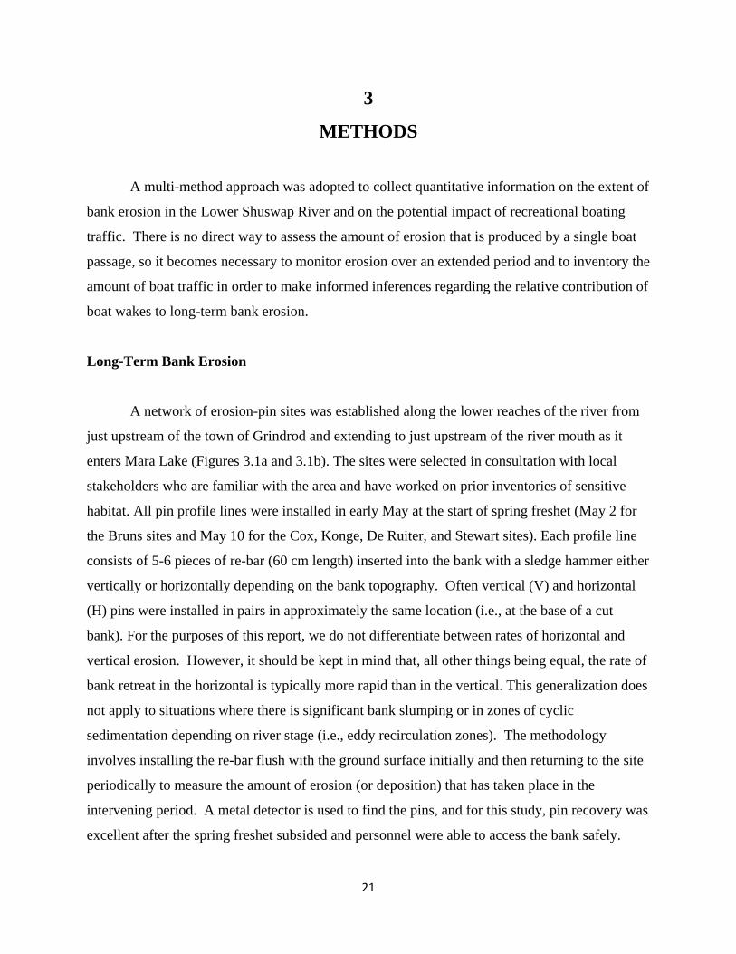
A multi-method approach was adopted to collect quantitative information on the extent of
bank erosion in the Lower Shuswap River and on the potential impact of recreational boating
traffic. There is no direct way to assess the amount of erosion that is produced by a single boat
passage, so it becomes necessary to monitor erosion over an extended period and to inventory the
amount of boat traffic in order to make informed inferences regarding the relative contribution of
boat wakes to long-term bank erosion.
Long-Term Bank Erosion
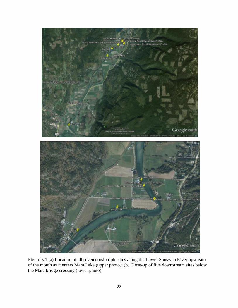
A network of erosion-pin sites was established along the lower reaches of the river from
just upstream of the town of Grindrod and extending to just upstream of the river mouth as it
enters Mara Lake (Figures 3.1a and 3.1b). The sites were selected in consultation with local
stakeholders who are familiar with the area and have worked on prior inventories of sensitive
habitat. All pin profile lines were installed in early May at the start of spring freshet (May 2 for
the Bruns sites and May 10 for the Cox, Konge, De Ruiter, and Stewart sites). Each profile line
consists of 5-6 pieces of re-bar (60 cm length) inserted into the bank with a sledge hammer either
vertically or horizontally depending on the bank topography. Often vertical (V) and horizontal
(H) pins were installed in pairs in approximately the same location (i.e., at the base of a cut
bank). For the purposes of this report, we do not differentiate between rates of horizontal and
vertical erosion. However, it should be kept in mind that, all other things being equal, the rate of
bank retreat in the horizontal is typically more rapid than in the vertical. This generalization does
not apply to situations where there is significant bank slumping or in zones of cyclic
sedimentation depending on river stage (i.e., eddy recirculation zones). The methodology
involves installing the re-bar flush with the ground surface initially and then returning to the site
periodically to measure the amount of erosion (or deposition) that has taken place in the
intervening period. A metal detector is used to find the pins, and for this study, pin recovery was
excellent after the spring freshet subsided and personnel were able to access the bank safely.
22
Figure 3.1 (a) Location of all seven erosion-pin sites along the Lower Shuswap River upstream of the mouth as it enters Mara Lake (upper photo); (b) Close-up of five downstream sites below the Mara bridge crossing (lower photo).
23
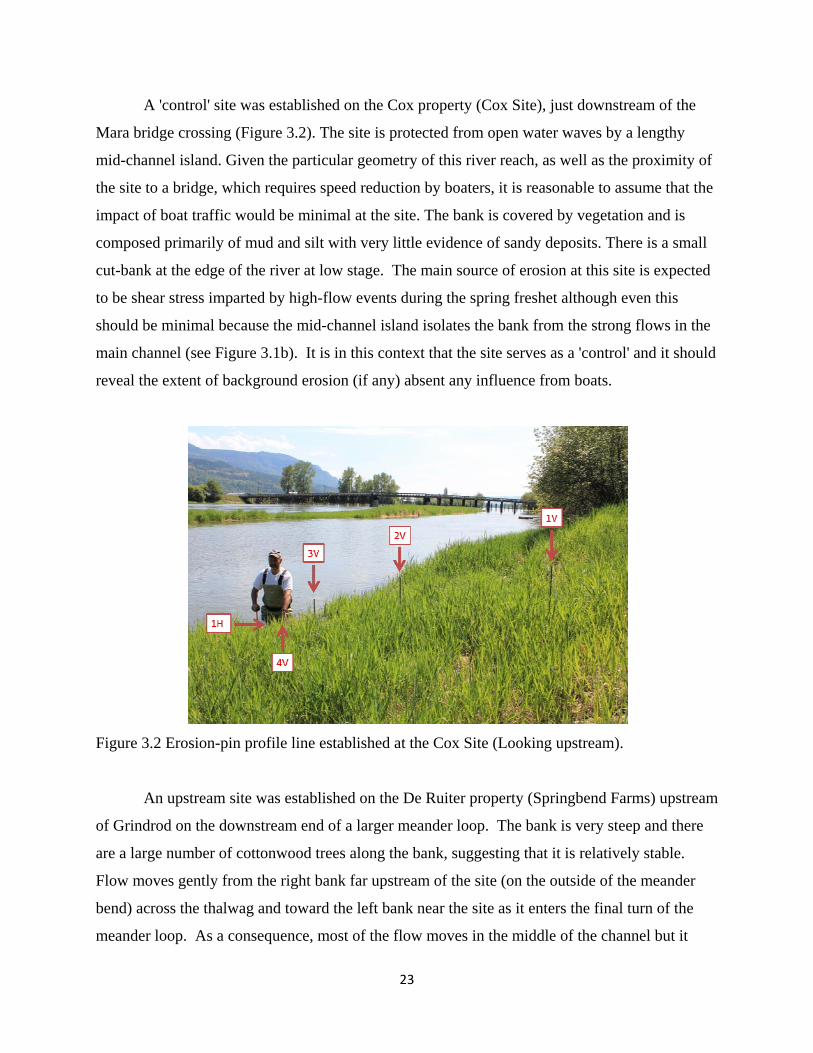
A 'control' site was established on the Cox property (Cox Site), just downstream of the
Mara bridge crossing (Figure 3.2). The site is protected from open water waves by a lengthy
mid-channel island. Given the particular geometry of this river reach, as well as the proximity of
the site to a bridge, which requires speed reduction by boaters, it is reasonable to assume that the
impact of boat traffic would be minimal at the site. The bank is covered by vegetation and is
composed primarily of mud and silt with very little evidence of sandy deposits. There is a small
cut-bank at the edge of the river at low stage. The main source of erosion at this site is expected
to be shear stress imparted by high-flow events during the spring freshet although even this
should be minimal because the mid-channel island isolates the bank from the strong flows in the
main channel (see Figure 3.1b). It is in this context that the site serves as a 'control' and it should
reveal the extent of background erosion (if any) absent any influence from boats.
Figure 3.2 Erosion-pin profile line established at the Cox Site (Looking upstream).
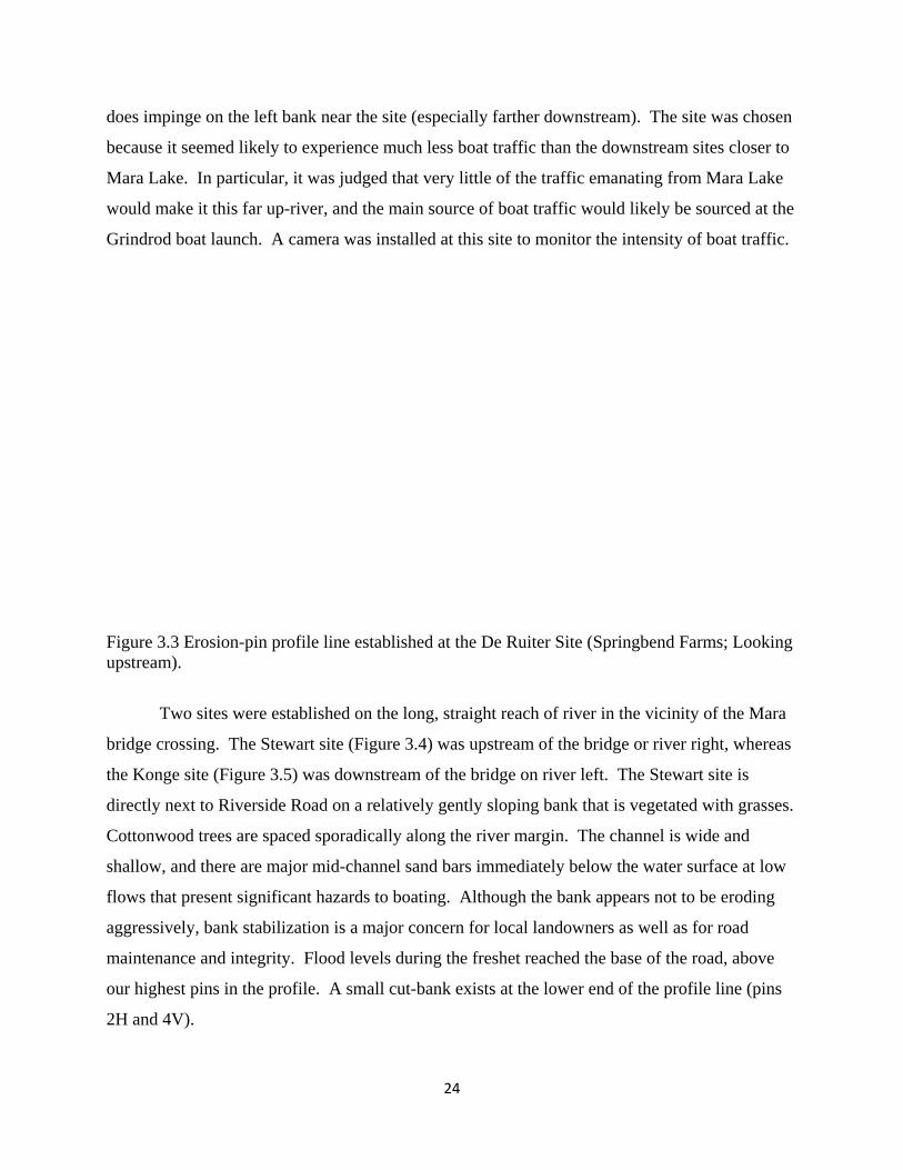
An upstream site was established on the De Ruiter property (Springbend Farms) upstream
of Grindrod on the downstream end of a larger meander loop. The bank is very steep and there
are a large number of cottonwood trees along the bank, suggesting that it is relatively stable.
Flow moves gently from the right bank far upstream of the site (on the outside of the meander
bend) across the thalwag and toward the left bank near the site as it enters the final turn of the
meander loop. As a consequence, most of the flow moves in the middle of the channel but it
24
does impinge on the left bank near the site (especially farther downstream). The site was chosen
because it seemed likely to experience much less boat traffic than the downstream sites closer to
Mara Lake. In particular, it was judged that very little of the traffic emanating from Mara Lake
would make it this far up-river, and the main source of boat traffic would likely be sourced at the
Grindrod boat launch. A camera was installed at this site to monitor the intensity of boat traffic.
Figure 3.3 Erosion-pin profile line established at the De Ruiter Site (Springbend Farms; Looking upstream).
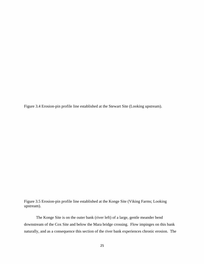
Two sites were established on the long, straight reach of river in the vicinity of the Mara
bridge crossing. The Stewart site (Figure 3.4) was upstream of the bridge or river right, whereas
the Konge site (Figure 3.5) was downstream of the bridge on river left. The Stewart site is
directly next to Riverside Road on a relatively gently sloping bank that is vegetated with grasses.
Cottonwood trees are spaced sporadically along the river margin. The channel is wide and
shallow, and there are major mid-channel sand bars immediately below the water surface at low
flows that present significant hazards to boating. Although the bank appears not to be eroding
aggressively, bank stabilization is a major concern for local landowners as well as for road
maintenance and integrity. Flood levels during the freshet reached the base of the road, above
our highest pins in the profile. A small cut-bank exists at the lower end of the profile line (pins
2H and 4V).
25
Figure 3.4 Erosion-pin profile line established at the Stewart Site (Looking upstream).
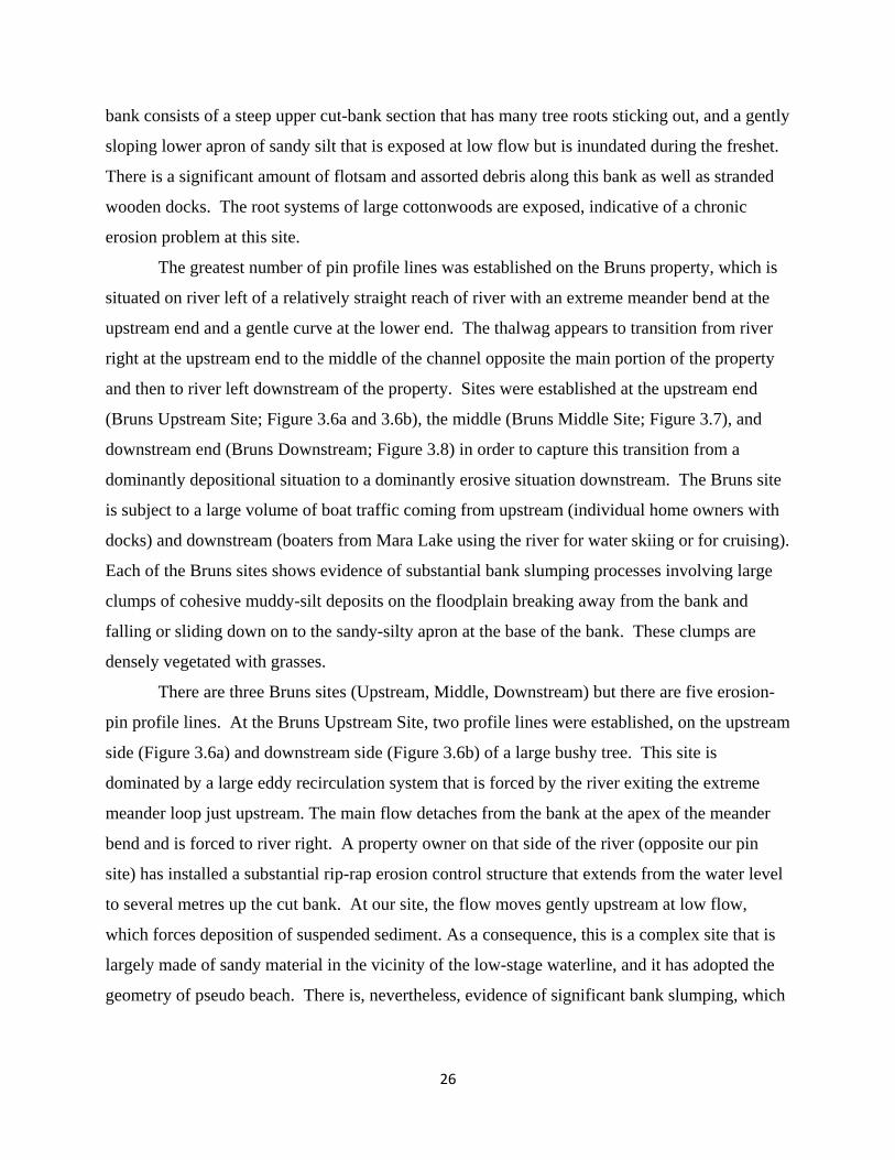
Figure 3.5 Erosion-pin profile line established at the Konge Site (Viking Farms; Looking upstream).
The Konge Site is on the outer bank (river left) of a large, gentle meander bend
downstream of the Cox Site and below the Mara bridge crossing. Flow impinges on this bank
naturally, and as a consequence this section of the river bank experiences chronic erosion. The
26
bank consists of a steep upper cut-bank section that has many tree roots sticking out, and a gently
sloping lower apron of sandy silt that is exposed at low flow but is inundated during the freshet.
There is a significant amount of flotsam and assorted debris along this bank as well as stranded
wooden docks. The root systems of large cottonwoods are exposed, indicative of a chronic
erosion problem at this site.
The greatest number of pin profile lines was established on the Bruns property, which is
situated on river left of a relatively straight reach of river with an extreme meander bend at the
upstream end and a gentle curve at the lower end. The thalwag appears to transition from river
right at the upstream end to the middle of the channel opposite the main portion of the property
and then to river left downstream of the property. Sites were established at the upstream end
(Bruns Upstream Site; Figure 3.6a and 3.6b), the middle (Bruns Middle Site; Figure 3.7), and
downstream end (Bruns Downstream; Figure 3.8) in order to capture this transition from a
dominantly depositional situation to a dominantly erosive situation downstream. The Bruns site
is subject to a large volume of boat traffic coming from upstream (individual home owners with
docks) and downstream (boaters from Mara Lake using the river for water skiing or for cruising).
Each of the Bruns sites shows evidence of substantial bank slumping processes involving large
clumps of cohesive muddy-silt deposits on the floodplain breaking away from the bank and
falling or sliding down on to the sandy-silty apron at the base of the bank. These clumps are
densely vegetated with grasses.
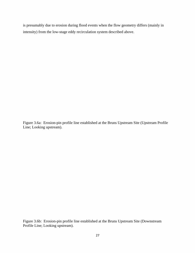
There are three Bruns sites (Upstream, Middle, Downstream) but there are five erosion-
pin profile lines. At the Bruns Upstream Site, two profile lines were established, on the upstream
side (Figure 3.6a) and downstream side (Figure 3.6b) of a large bushy tree. This site is
dominated by a large eddy recirculation system that is forced by the river exiting the extreme
meander loop just upstream. The main flow detaches from the bank at the apex of the meander
bend and is forced to river right. A property owner on that side of the river (opposite our pin
site) has installed a substantial rip-rap erosion control structure that extends from the water level
to several metres up the cut bank. At our site, the flow moves gently upstream at low flow,
which forces deposition of suspended sediment. As a consequence, this is a complex site that is
largely made of sandy material in the vicinity of the low-stage waterline, and it has adopted the
geometry of pseudo beach. There is, nevertheless, evidence of significant bank slumping, which
27
is presumably due to erosion during flood events when the flow geometry differs (mainly in
intensity) from the low-stage eddy recirculation system described above.
Figure 3.6a: Erosion-pin profile line established at the Bruns Upstream Site (Upstream Profile Line; Looking upstream).
Figure 3.6b: Erosion-pin profile line established at the Bruns Upstream Site (Downstream Profile Line; Looking upstream).
28
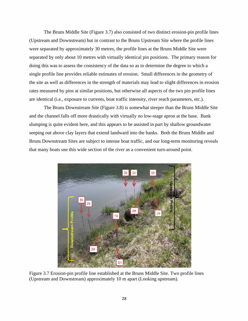
The Bruns Middle Site (Figure 3.7) also consisted of two distinct erosion-pin profile lines
(Upstream and Downstream) but in contrast to the Bruns Upstream Site where the profile lines
were separated by approximately 30 metres, the profile lines at the Bruns Middle Site were
separated by only about 10 metres with virtually identical pin positions. The primary reason for
doing this was to assess the consistency of the data so as to determine the degree to which a
single profile line provides reliable estimates of erosion. Small differences in the geometry of
the site as well as differences in the strength of materials may lead to slight differences in erosion
rates measured by pins at similar positions, but otherwise all aspects of the two pin profile lines
are identical (i.e., exposure to currents, boat traffic intensity, river reach parameters, etc.).
The Bruns Downstream Site (Figure 3.8) is somewhat steeper than the Bruns Middle Site
and the channel falls off more drastically with virtually no low-stage apron at the base. Bank
slumping is quite evident here, and this appears to be assisted in part by shallow groundwater
seeping out above clay layers that extend landward into the banks. Both the Bruns Middle and
Bruns Downstream Sites are subject to intense boat traffic, and our long-term monitoring reveals
that many boats use this wide section of the river as a convenient turn-around point.
Figure 3.7 Erosion-pin profile line established at the Bruns Middle Site. Two profile lines (Upstream and Downstream) approximately 10 m apart (Looking upstream).
29
Figure 3.8 Erosion-pin profile line established at the Bruns Downstream Site (Looking downstream).
Long-Term Boat Traffic Monitoring
Despite the common assertion (in many places across the world) that boats cause
significant shoreline erosion, there are surprisingly few data sets on boat traffic intensity.
Without such data on how many boats actually use the waterway, as well as information on the
type of vessel and speed, it is impossible to assess what the relative contribution of boat wakes is
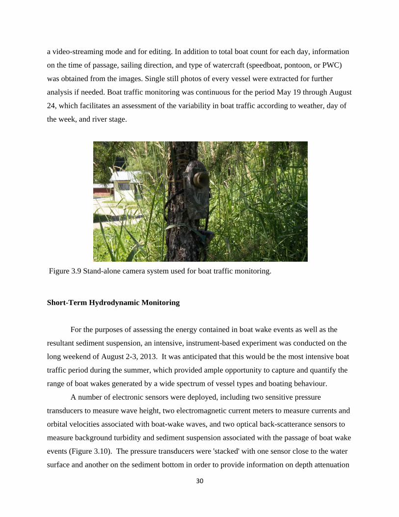
to the erosion problem. For this study, two automatically triggered cameras (PlotWatcherTM Pro)
were deployed beginning in mid-May, well before any significant boat traffic appeared on the
river. One camera was installed on the Bruns property (Figure 3. 9), where boat traffic was
expected to be quite intense. Another camera was installed on the De Ruiter property upstream
of Grindrod. The cameras were programmed to capture an image every three seconds from 5 am
until 10 pm, daily. The digital images were stored on an internal memory card that was replaced
during routine maintenance visits. The memory cards had a 64 Gbyte capacity and they tended
to fill up in about 10 days, so a weekly service schedule was adopted. Batteries required
replacement every three to four weeks. The digital images were downloaded on to a PC, and
proprietary software (GameFinderTM) that came with the camera was used to watch the images in
30
a video-streaming mode and for editing. In addition to total boat count for each day, information
on the time of passage, sailing direction, and type of watercraft (speedboat, pontoon, or PWC)
was obtained from the images. Single still photos of every vessel were extracted for further
analysis if needed. Boat traffic monitoring was continuous for the period May 19 through August
24, which facilitates an assessment of the variability in boat traffic according to weather, day of
the week, and river stage.
Figure 3.9 Stand-alone camera system used for boat traffic monitoring.
Short-Term Hydrodynamic Monitoring
For the purposes of assessing the energy contained in boat wake events as well as the
resultant sediment suspension, an intensive, instrument-based experiment was conducted on the
long weekend of August 2-3, 2013. It was anticipated that this would be the most intensive boat
traffic period during the summer, which provided ample opportunity to capture and quantify the
range of boat wakes generated by a wide spectrum of vessel types and boating behaviour.
A number of electronic sensors were deployed, including two sensitive pressure
transducers to measure wave height, two electromagnetic current meters to measure currents and
orbital velocities associated with boat-wake waves, and two optical back-scatterance sensors to
measure background turbidity and sediment suspension associated with the passage of boat wake
events (Figure 3.10). The pressure transducers were 'stacked' with one sensor close to the water
surface and another on the sediment bottom in order to provide information on depth attenuation
31
of the wave signal. The current meters and turbidity probes were paired, with one set deployed
very close to the shoreline in shallow water and another set in somewhat deeper water. In this
report we will present data only from the shallow water instrument set. The raw data from these
instruments was collected on a high-speed data acquisition system at 8 Hz, and then converted to
usable information using instrument calibration curves and linear wave theory.
Figure 3.10 Instrumentation deployment scheme at Bruns Middle Site.
Whenever a boat passage occurred, the data acquisition system was turned on, a
photograph of the boat was taken, and notations were made in the field book. This protocol
allowed us to connect the hydrodynamic records to the type of boat that generated the wake. In
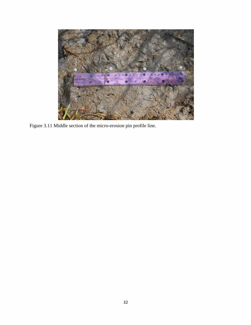
addition, a profile line of micro-erosion pins was installed at the experimental site (Figure 3.11)
to provide information regarding the amount of erosion that occurred during the two-day
experimental period. The majority of the micro-pins were installed on Friday August 2; more
pins were added at the end of the profile (in deeper water) on the morning of Saturday August 3
when the water was less turbid and visibility allowed careful placement. A pocket shear vane
(TorvaneTM) was used to evaluate the strength of cohesive bank materials in the vicinity of the
micro-erosion pin profile.
32
Figure 3.11 Middle section of the micro-erosion pin profile line.
33
4
RESULTS
In this chapter a brief summary is provided of the data collected during the project, and
where appropriate, we also offer a preliminary assessment of the implications of these data in the
context of the project objectives.
Erosion-Pin Profile Lines
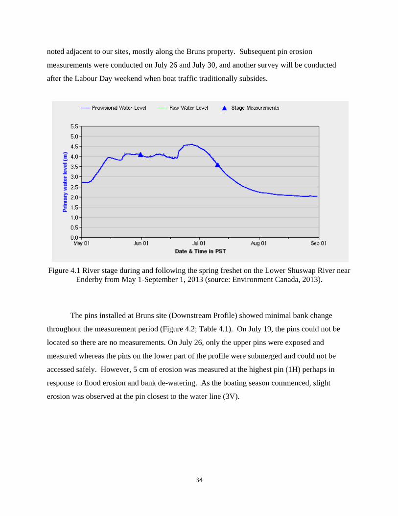
The erosion-pin profile lines were established on the rising limb of the spring freshet in
early May, and the pins were subsequently inundated with water as the stage rose during the
spring snowmelt season. Figure 4.1 shows that the maximum stage of approximately 4.6 m
above datum occurred at the end of June, and a gradual decline to a low of about 2.1 m occurred
during most of July.
All pins at every site were covered with water during the high stage, which lasted from
late May to the beginning of July. It proved far too risky to measure the pins until the stage
declined to a level where the pins were exposed to air or were safely accessible despite partial
submergence. Consequently, the first pin measurements were not taken until July 19, 2013, at
which time the stage was about 3 m which is similar to the installation stage. The upper pins
were exposed while the lower pins were still submerged. This first round of pin measurements is
therefore thought to quantify the degree of bank change resulting predominantly from flood
flows rather than boat traffic. Although the boating season had commenced by early July, the
intensity of boat traffic was relatively moderate due to high discharge and un-seasonally cool
weather. More importantly, due to high river stage the energy of boat-generated waves would
not have influenced the substrate at most of the pins along the profile and would only have
impacted the river bank at the uppermost pins. Geotechnical forces associated with rising and
falling water levels due to varying discharge during the spring freshet alters the pore pressure
and cohesive strength of bank materials, and this often leads to bank slumping events during the
declining limb of the seasonal hydrograph (e.g., Bauer et al., 2002). There was little visible
evidence of new bank slumping apparent at our pin sites although several fresh slumps were
34
noted adjacent to our sites, mostly along the Bruns property. Subsequent pin erosion
measurements were conducted on July 26 and July 30, and another survey will be conducted
after the Labour Day weekend when boat traffic traditionally subsides.
Figure 4.1 River stage during and following the spring freshet on the Lower Shuswap River near Enderby from May 1-September 1, 2013 (source: Environment Canada, 2013).
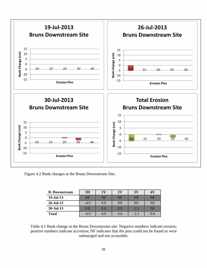
The pins installed at Bruns site (Downstream Profile) showed minimal bank change
throughout the measurement period (Figure 4.2; Table 4.1). On July 19, the pins could not be
located so there are no measurements. On July 26, only the upper pins were exposed and
measured whereas the pins on the lower part of the profile were submerged and could not be
accessed safely. However, 5 cm of erosion was measured at the highest pin (1H) perhaps in
response to flood erosion and bank de-watering. As the boating season commenced, slight
erosion was observed at the pin closest to the water line (3V).
35
Figure 4.2 Bank changes at the Bruns Downstream Site.
B. Downstream 1H 1V 2V 3V 4V
19-Jul-13 NF NF NF NF NF
26-Jul-13 -4.9 0.0 NF NF NF
30-Jul-13 0.0 0.0 0.6 -2.1 NF
Total -4.9 0.0 0.6 -2.1 0.0
Table 4.1 Bank change at the Bruns Downstream site. Negative numbers indicate erosion; positive numbers indicate accretion; NF indicates that the pins could not be found or were
submerged and not accessible.
‐15
‐10
‐5
0
5
10
15
1H 1V 2V 3V 4V
Ban
k Chan
ge (cm
)
Erosion Pins
19‐Jul‐2013Bruns Downstream Site
‐15
‐10
‐5
0
5
10
15
1H 1V 2H 2V 3V
Ban
k Chan
ge (cm
)
Erosion Pins
26‐Jul‐2013Bruns Downstream Site
‐15
‐10
‐5
0
5
10
15
1H 1V 2V 3V 4V
Ban
k Chan
ge (cm
)
Erosion Pins
30‐Jul‐2013Bruns Downstream Site
‐15
‐10
‐5
0
5
10
15
1H 1V 2V 3V 4V
Ban
k Chan
ge (cm
)
Erosion Pins
Total ErosionBruns Downstream Site
36
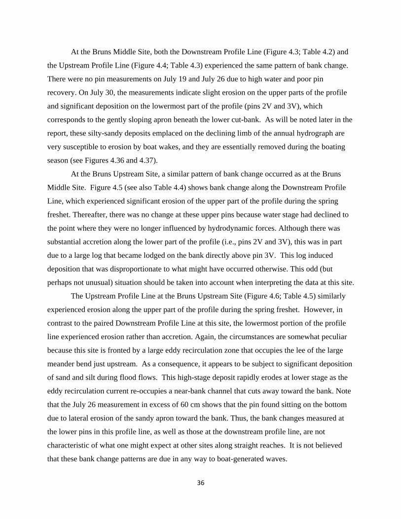
At the Bruns Middle Site, both the Downstream Profile Line (Figure 4.3; Table 4.2) and
the Upstream Profile Line (Figure 4.4; Table 4.3) experienced the same pattern of bank change.
There were no pin measurements on July 19 and July 26 due to high water and poor pin
recovery. On July 30, the measurements indicate slight erosion on the upper parts of the profile
and significant deposition on the lowermost part of the profile (pins 2V and 3V), which
corresponds to the gently sloping apron beneath the lower cut-bank. As will be noted later in the
report, these silty-sandy deposits emplaced on the declining limb of the annual hydrograph are
very susceptible to erosion by boat wakes, and they are essentially removed during the boating
season (see Figures 4.36 and 4.37).
At the Bruns Upstream Site, a similar pattern of bank change occurred as at the Bruns
Middle Site. Figure 4.5 (see also Table 4.4) shows bank change along the Downstream Profile
Line, which experienced significant erosion of the upper part of the profile during the spring
freshet. Thereafter, there was no change at these upper pins because water stage had declined to
the point where they were no longer influenced by hydrodynamic forces. Although there was
substantial accretion along the lower part of the profile (i.e., pins 2V and 3V), this was in part
due to a large log that became lodged on the bank directly above pin 3V. This log induced
deposition that was disproportionate to what might have occurred otherwise. This odd (but
perhaps not unusual) situation should be taken into account when interpreting the data at this site.
The Upstream Profile Line at the Bruns Upstream Site (Figure 4.6; Table 4.5) similarly
experienced erosion along the upper part of the profile during the spring freshet. However, in
contrast to the paired Downstream Profile Line at this site, the lowermost portion of the profile
line experienced erosion rather than accretion. Again, the circumstances are somewhat peculiar
because this site is fronted by a large eddy recirculation zone that occupies the lee of the large
meander bend just upstream. As a consequence, it appears to be subject to significant deposition
of sand and silt during flood flows. This high-stage deposit rapidly erodes at lower stage as the
eddy recirculation current re-occupies a near-bank channel that cuts away toward the bank. Note
that the July 26 measurement in excess of 60 cm shows that the pin found sitting on the bottom
due to lateral erosion of the sandy apron toward the bank. Thus, the bank changes measured at
the lower pins in this profile line, as well as those at the downstream profile line, are not
characteristic of what one might expect at other sites along straight reaches. It is not believed
that these bank change patterns are due in any way to boat-generated waves.
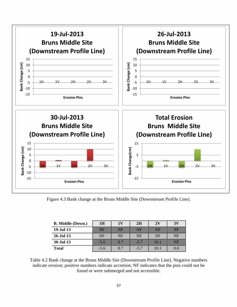
37
Figure 4.3 Bank change at the Bruns Middle Site (Downstream Profile Line).
B. Middle (Down.) 1H 1V 2H 2V 3V
19-Jul-13 NF NF NF NF NF
26-Jul-13 NF NF NF NF NF
30-Jul-13 -5.6 0.7 -5.7 10.1 NF
Total -5.6 0.7 -5.7 10.1 0.0
Table 4.2 Bank change at the Bruns Middle Site (Downstream Profile Line). Negative numbers
indicate erosion; positive numbers indicate accretion; NF indicates that the pins could not be found or were submerged and not accessible.
‐15
‐10
‐5
0
5
10
15
1H 1V 2H 2V 3V
Ban
k Chan
ge (cm
)
Erosion Pins
19‐Jul‐2013 Bruns Middle Site
(Downstream Profile Line)
‐15
‐10
‐5
0
5
10
15
1H 1V 2H 2V 3V
Ban
k Chan
ge (cm
)
Erosion Pins
26‐Jul‐2013Bruns Middle Site
(Downstream Profile Line)
‐15
‐10
‐5
0
5
10
15
1H 1V 2H 2V 3V
Ban
k Chan
ge (cm
)
Erosion Pins
30‐Jul‐2013Bruns Middle Site
(Downstream Profile Line)
‐15
‐5
5
15
1H 1V 2H 2V 3V
Ban
k Chan
ge(cm)
Erosion Pins
Total ErosionBruns Middle Site
(Downstream Profile LIne)
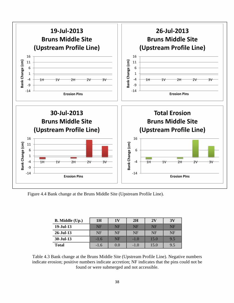
38
Figure 4.4 Bank change at the Bruns Middle Site (Upstream Profile Line).
B. Middle (Up.) 1H 1V 2H 2V 3V
19-Jul-13 NF NF NF NF NF
26-Jul-13 NF NF NF NF NF
30-Jul-13 -1.6 NF -1.0 15.0 9.5
Total -1.6 0.0 -1.0 15.0 9.5
Table 4.3 Bank change at the Bruns Middle Site (Upstream Profile Line). Negative numbers indicate erosion; positive numbers indicate accretion; NF indicates that the pins could not be
found or were submerged and not accessible.
‐14
‐9
‐4
1
6
11
16
1H 1V 2H 2V 3V
Ban
k Chan
ge (cm
)
Erosion Pins
19‐Jul‐2013Bruns Middle Site
(Upstream Profile Line)
‐14
‐9
‐4
1
6
11
16
1H 1V 2H 2V 3V
Ban
k Chan
ge (cm
)
Erosion Pins
26‐Jul‐2013Bruns Middle Site
(Upstream Profile Line)
‐14
‐9
‐4
1
6
11
16
1H 1V 2H 2V 3V
Ban
k Chan
ge (cm
)
Erosion Pins
30‐Jul‐2013Bruns Middle Site
(Upstream Profile Line)
‐14
‐4
6
16
1H 1V 2H 2V 3V
Ban
k Chan
ge (cm
)
Erosion PIns
Total ErosionBruns Middle Site
(Upstream Profile Line)
39
Figure 4.5 Bank change at the Bruns Upstream Site (Downstream Profile Line).
B. Upstream (Down.) 1H 2H 3H 1V 2V 3V
19-Jul-13 -4.9 -0.2 NF NF NF NF
26-Jul-13 0.0 0.0 -0.1 2.8 6.2 NF
30-Jul-13 0.0 0.0 -0.1 0.0 8.4 24.0
Total -4.9 -0.2 -0.2 2.8 14.6 24.0
Table 4.4 Bank change at the Bruns Upstream Site (Downstream Profile Line). Negative
numbers indicate erosion; positive numbers indicate accretion; NF indicates that the pins could not be found or were submerged and not accessible.
‐15
‐5
5
15
25
1H 2H 3H 1V 2V 3V
Ban
k Chan
ge (cm
)
Erosion Pins
19‐Jul‐2013 Bruns Upstream Site
(Downstream Profile Line)
‐15
‐5
5
15
25
1H 2H 3H 1V 2V 3V
Ban
k Chan
ge (cm
)
Erosion Pins
26‐Jul‐2013 Bruns Upstream Site
(Downstream Profile Line)
‐15
‐5
5
15
25
1H 2H 3H 1V 2V 3V
Ban
k Chan
ge (cm
)
Erosion Pins
30‐Jul‐2013 Bruns Upstream Site
(Downstream Profile Line)
‐15
‐5
5
15
25
1H 2H 3H 1V 2V 3V
Ban
k Chan
ge (cm
)
Erosion Pins
Total ErosionBruns Upstream Site
(Downstream Profile Line)
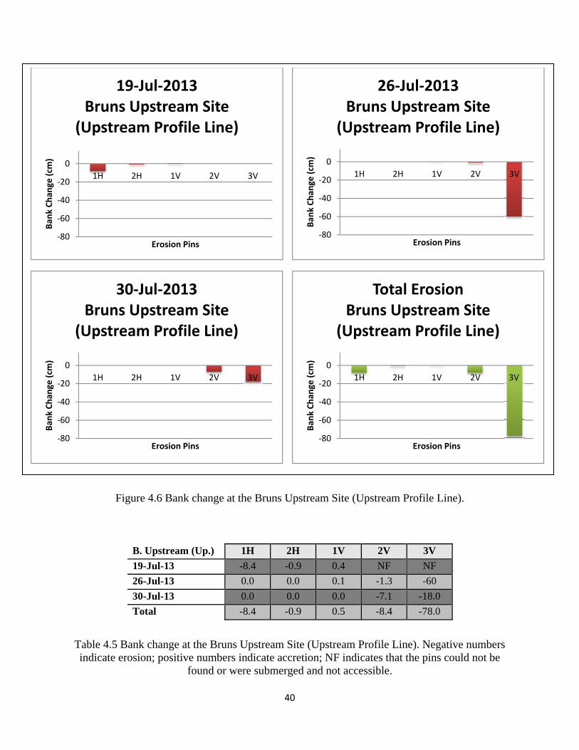
40
Figure 4.6 Bank change at the Bruns Upstream Site (Upstream Profile Line).
B. Upstream (Up.) 1H 2H 1V 2V 3V
19-Jul-13 -8.4 -0.9 0.4 NF NF
26-Jul-13 0.0 0.0 0.1 -1.3 -60
30-Jul-13 0.0 0.0 0.0 -7.1 -18.0
Total -8.4 -0.9 0.5 -8.4 -78.0
Table 4.5 Bank change at the Bruns Upstream Site (Upstream Profile Line). Negative numbers indicate erosion; positive numbers indicate accretion; NF indicates that the pins could not be
found or were submerged and not accessible.
‐80
‐60
‐40
‐20
0
1H 2H 1V 2V 3V
Ban
k Chan
ge (cm
)
Erosion Pins
19‐Jul‐2013Bruns Upstream Site
(Upstream Profile Line)
‐80
‐60
‐40
‐20
0
1H 2H 1V 2V 3V
Ban
k Chan
ge (cm
)
Erosion Pins
26‐Jul‐2013Bruns Upstream Site
(Upstream Profile Line)
‐80
‐60
‐40
‐20
0
1H 2H 1V 2V 3V
Ban
k Chan
ge (cm
)
Erosion Pins
30‐Jul‐2013Bruns Upstream Site
(Upstream Profile Line)
‐80
‐60
‐40
‐20
0
1H 2H 1V 2V 3V
Ban
k Chan
ge (cm
)
Erosion Pins
Total ErosionBruns Upstream Site
(Upstream Profile Line)
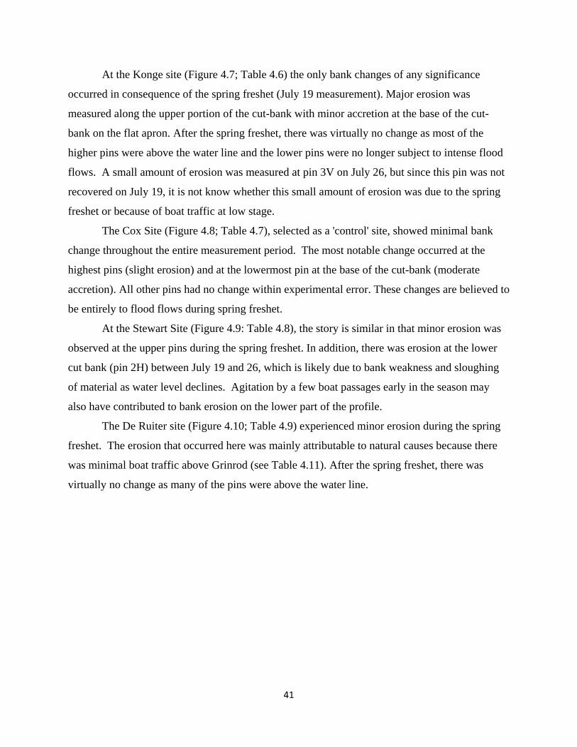
41
At the Konge site (Figure 4.7; Table 4.6) the only bank changes of any significance
occurred in consequence of the spring freshet (July 19 measurement). Major erosion was
measured along the upper portion of the cut-bank with minor accretion at the base of the cut-
bank on the flat apron. After the spring freshet, there was virtually no change as most of the
higher pins were above the water line and the lower pins were no longer subject to intense flood
flows. A small amount of erosion was measured at pin 3V on July 26, but since this pin was not
recovered on July 19, it is not know whether this small amount of erosion was due to the spring
freshet or because of boat traffic at low stage.
The Cox Site (Figure 4.8; Table 4.7), selected as a 'control' site, showed minimal bank
change throughout the entire measurement period. The most notable change occurred at the
highest pins (slight erosion) and at the lowermost pin at the base of the cut-bank (moderate
accretion). All other pins had no change within experimental error. These changes are believed to
be entirely to flood flows during spring freshet.
At the Stewart Site (Figure 4.9: Table 4.8), the story is similar in that minor erosion was
observed at the upper pins during the spring freshet. In addition, there was erosion at the lower
cut bank (pin 2H) between July 19 and 26, which is likely due to bank weakness and sloughing
of material as water level declines. Agitation by a few boat passages early in the season may
also have contributed to bank erosion on the lower part of the profile.
The De Ruiter site (Figure 4.10; Table 4.9) experienced minor erosion during the spring
freshet. The erosion that occurred here was mainly attributable to natural causes because there
was minimal boat traffic above Grinrod (see Table 4.11). After the spring freshet, there was
virtually no change as many of the pins were above the water line.
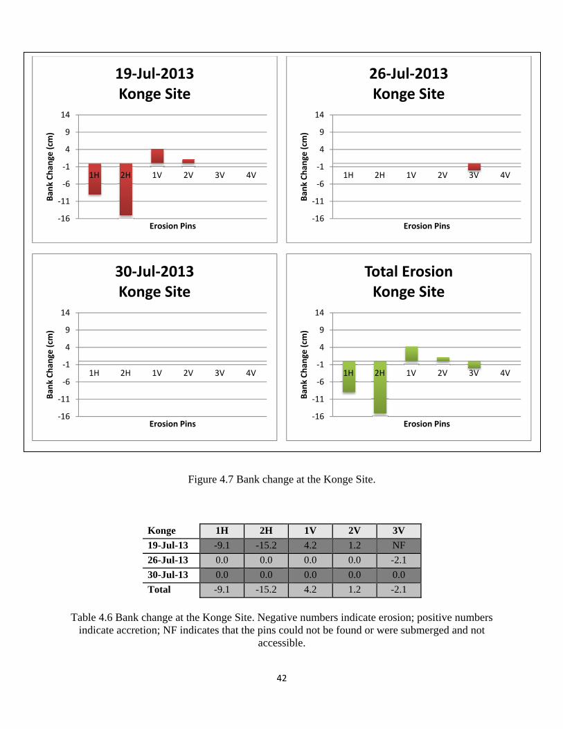
42
Figure 4.7 Bank change at the Konge Site.
Konge 1H 2H 1V 2V 3V
19-Jul-13 -9.1 -15.2 4.2 1.2 NF
26-Jul-13 0.0 0.0 0.0 0.0 -2.1
30-Jul-13 0.0 0.0 0.0 0.0 0.0
Total -9.1 -15.2 4.2 1.2 -2.1
Table 4.6 Bank change at the Konge Site. Negative numbers indicate erosion; positive numbers
indicate accretion; NF indicates that the pins could not be found or were submerged and not accessible.
‐16
‐11
‐6
‐1
4
9
14
1H 2H 1V 2V 3V 4V
Ban
k Chan
ge (cm
)
Erosion Pins
19‐Jul‐2013Konge Site
‐16
‐11
‐6
‐1
4
9
14
1H 2H 1V 2V 3V 4V
Ban
k Chan
ge (cm
)
Erosion Pins
26‐Jul‐2013Konge Site
‐16
‐11
‐6
‐1
4
9
14
1H 2H 1V 2V 3V 4V
Ban
k Chan
ge (cm
)
Erosion Pins
30‐Jul‐2013Konge Site
‐16
‐11
‐6
‐1
4
9
14
1H 2H 1V 2V 3V 4V
Ban
k Chan
ge (cm
)
Erosion Pins
Total ErosionKonge Site
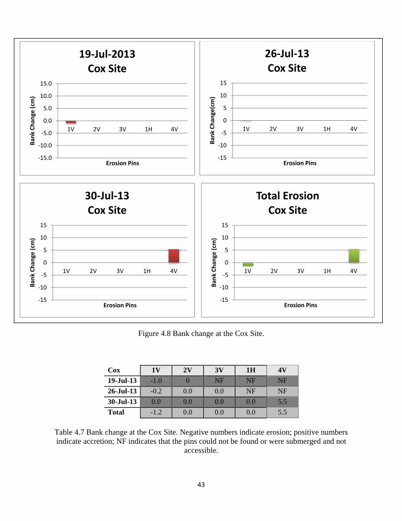
43
Figure 4.8 Bank change at the Cox Site.
Cox 1V 2V 3V 1H 4V
19-Jul-13 -1.0 0 NF NF NF
26-Jul-13 -0.2 0.0 0.0 NF NF
30-Jul-13 0.0 0.0 0.0 0.0 5.5
Total -1.2 0.0 0.0 0.0 5.5
Table 4.7 Bank change at the Cox Site. Negative numbers indicate erosion; positive numbers indicate accretion; NF indicates that the pins could not be found or were submerged and not
accessible.
‐15.0
‐10.0
‐5.0
0.0
5.0
10.0
15.0
1V 2V 3V 1H 4V
Ban
k Chan
ge (cm
)
Erosion Pins
19‐Jul‐2013Cox Site
‐15
‐10
‐5
0
5
10
15
1V 2V 3V 1H 4V
Ban
k Chan
ge(cm)
Erosion Pins
26‐Jul‐13Cox Site
‐15
‐10
‐5
0
5
10
15
1V 2V 3V 1H 4V
Ban
k Chan
ge (cm
)
Erosion Pins
30‐Jul‐13Cox Site
‐15
‐10
‐5
0
5
10
15
1V 2V 3V 1H 4V
Ban
k Chan
ge (cm
)
Erosion Pins
Total ErosionCox Site
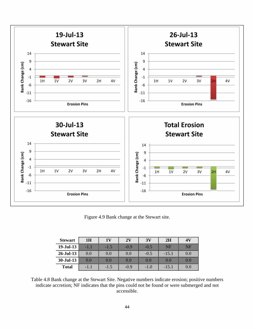
44
Figure 4.9 Bank change at the Stewart site.
Stewart 1H 1V 2V 3V 2H 4V
19-Jul-13 -1.1 -1.5 -0.9 -0.5 NF NF
26-Jul-13 0.0 0.0 0.0 -0.5 -15.1 0.0
30-Jul-13 0.0 0.0 0.0 0.0 0.0 0.0
Total -1.1 -1.5 -0.9 -1.0 -15.1 0.0
Table 4.8 Bank change at the Stewart Site. Negative numbers indicate erosion; positive numbers
indicate accretion; NF indicates that the pins could not be found or were submerged and not accessible.
‐16
‐11
‐6
‐1
4
9
14
1H 1V 2V 3V 2H 4V
Ban
k Chan
ge (cm
)
Erosion Pins
19‐Jul‐13Stewart Site
‐16
‐11
‐6
‐1
4
9
14
1H 1V 2V 3V 2H 4V
Ban
k Chan
ge (cm
)
Erosion Pins
26‐Jul‐13Stewart Site
‐16
‐11
‐6
‐1
4
9
14
1H 1V 2V 3V 2H 4V
Ban
k Chan
ge (cm
)
Erosion Pins
30‐Jul‐13Stewart Site
‐16
‐11
‐6
‐1
4
9
14
1H 1V 2V 3V 2H 4V
Ban
k Chan
ge (cm
)
Erosion Pins
Total ErosionStewart Site
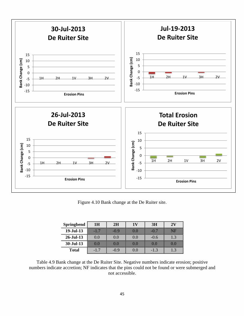
45
Figure 4.10 Bank change at the De Ruiter site.
Springbend 1H 2H 1V 3H 2V
19-Jul-13 -1.7 -0.9 0.0 -0.7 NF
26-Jul-13 0.0 0.0 0.0 -0.6 1.3
30-Jul-13 0.0 0.0 0.0 0.0 0.0
Total -1.7 -0.9 0.0 -1.3 1.3
Table 4.9 Bank change at the De Ruiter Site. Negative numbers indicate erosion; positive
numbers indicate accretion; NF indicates that the pins could not be found or were submerged and not accessible.
‐15
‐10
‐5
0
5
10
15
1H 2H 1V 3H 2V
Ban
k Chan
ge (cm
)
Erosion Pins
30‐Jul‐2013De Ruiter Site
‐15
‐10
‐5
0
5
10
15
1H 2H 1V 3H 2V
Ban
k Chan
ge (cm
)
Erosion Pins
Jul‐19‐2013De Ruiter Site
‐15
‐10
‐5
0
5
10
15
1H 2H 1V 3H 2V
Ban
k Chan
ge (cm
)
Erosion Pins
26‐Jul‐2013De Ruiter Site
‐15
‐10
‐5
0
5
10
15
1H 2H 1V 3H 2V
Ban
k Chan
ge (cm
)
Erosion Pins
Total ErosionDe Ruiter Site
46
Boat Traffic Survey
Although boats begin travelling the river in May, the traffic is quite restricted even over
the May the long weekend, likely because the weather is cool and the water is too cold for
recreational activities such as swimming and water skiing. In addition, the river currents during
high stage can be challenging and dangerous to recreational and casual boaters. Tables 4.10 –
4.13 and Figures 4.11 – 4.12, which are based on analysis of the remote camera images,
demonstrate that intense boating traffic was not observed until the July long weekend (June 28-
July 1). The peak boating season occurs between the July and August long weekends with a
noticeable decline in boat traffic intensity thereafter through to the end of August. This is
somewhat surprising given that August is traditionally a hot month with significant boating
traffic on the local lakes. It seems that the river environment is less desirable for boating in mid
August, perhaps because of the low water levels and shallow sand bars which likely pose
significant hazards to power boats and water skiers.
Weekends experienced more traffic than weekdays, and long weekends experienced the
greatest intensity of boat traffic. Clearly, this is due to the traditional work schedule of boat
owners as well as the opportunity provided by holidays. The weather, however, is a significant
factor in boat traffic. On extremely hot days boat numbers are at their highest and as the days get
longer, boaters appear to travel the river for as long as possible well into the evening hours while
there is still sunlight.
Both the Bruns and De Ruiter camera sites experienced the same general boating pattern
as regards seasonality and day of the week. However, the two camera sites saw very different
numbers of boats overall due to their spatial location. The Bruns site is located very close to
Mara Lake, which is a popular boating spot with a large number of cabins and resorts. The
proximity of the Bruns Site to Mara Lake thereby implies that a larger number of boats are likely
to venture past the property in contrast to sites farther upstream. The De Ruiter site is not located
close enough to any convenient boating areas or boat launches making it less popular for boating.
The stretch of river from Mara Lake to Grinrod (and then to the De Ruiter site) is much too long
for an average boating trip originating in Mara Lake, except for the most adventurous boaters.
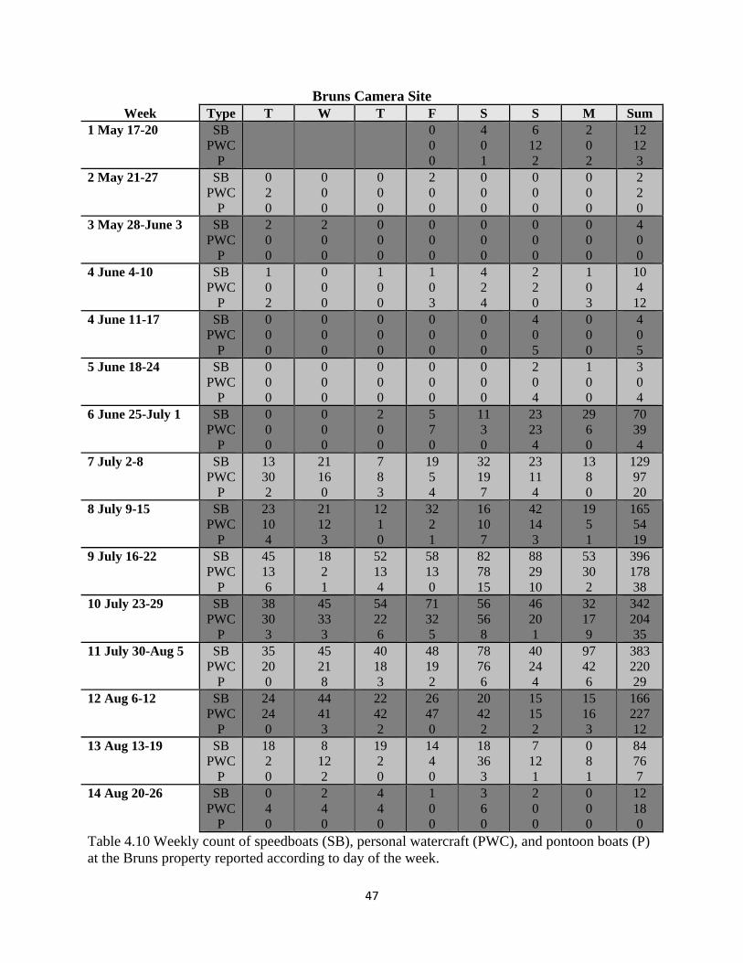
47
Bruns Camera Site Week Type T W T F S S M Sum
1 May 17-20 SB PWC
P
0 0 0
4 0 1
6 12 2
2 0 2
12 12 3
2 May 21-27 SB PWC
P
0 2 0
0 0 0
0 0 0
2 0 0
0 0 0
0 0 0
0 0 0
2 2 0
3 May 28-June 3 SB PWC
P
2 0 0
2 0 0
0 0 0
0 0 0
0 0 0
0 0 0
0 0 0
4 0 0
4 June 4-10 SB PWC
P
1 0 2
0 0 0
1 0 0
1 0 3
4 2 4
2 2 0
1 0 3
10 4
12 4 June 11-17 SB
PWC P
0 0 0
0 0 0
0 0 0
0 0 0
0 0 0
4 0 5
0 0 0
4 0 5
5 June 18-24 SB PWC
P
0 0 0
0 0 0
0 0 0
0 0 0
0 0 0
2 0 4
1 0 0
3 0 4
6 June 25-July 1 SB PWC
P
0 0 0
0 0 0
2 0 0
5 7 0
11 3 0
23 23 4
29 6 0
70 39 4
7 July 2-8 SB PWC
P
13 30 2
21 16 0
7 8 3
19 5 4
32 19 7
23 11 4
13 8 0
129 97 20
8 July 9-15 SB PWC
P
23 10 4
21 12 3
12 1 0
32 2 1
16 10 7
42 14 3
19 5 1
165 54 19
9 July 16-22 SB PWC
P
45 13 6
18 2 1
52 13 4
58 13 0
82 78 15
88 29 10
53 30 2
396 178 38
10 July 23-29 SB PWC
P
38 30 3
45 33 3
54 22 6
71 32 5
56 56 8
46 20 1
32 17 9
342 204 35
11 July 30-Aug 5 SB PWC
P
35 20 0
45 21 8
40 18 3
48 19 2
78 76 6
40 24 4
97 42 6
383 220 29
12 Aug 6-12 SB PWC
P
24 24 0
44 41 3
22 42 2
26 47 0
20 42 2
15 15 2
15 16 3
166 227 12
13 Aug 13-19 SB PWC
P
18 2 0
8 12 2
19 2 0
14 4 0
18 36 3
7 12 1
0 8 1
84 76 7
14 Aug 20-26 SB PWC
P
0 4 0
2 4 0
4 4 0
1 0 0
3 6 0
2 0 0
0 0 0
12 18 0
Table 4.10 Weekly count of speedboats (SB), personal watercraft (PWC), and pontoon boats (P) at the Bruns property reported according to day of the week.

48
De Ruiter Camera Site Week Type T W T F S S M Sum 1 May 17-20 SB
PWC P
5 0 0
2 0 3
3 0 2
0 0 0
10 0 5
2 May 21-27 SB PWC
P
0 2 0
0 0 0
0 0 0
0 0 0
0 0 0
0 0 0
0 0 0
0 2 0
3 May 28-June 3 SB PWC
P
0 0 0
0 0 0
0 0 0
1 0 1
0 0 0
0 0 0
2 2 0
3 2 1
4 June 4-10 SB PWC
P
0 0 0
2 0 0
4 0 0
0 0 0
0 0 0
0 0 0
0 0 0
6 0 0
5 June 11-17 SB PWC
P
0 0 2
0 2 0
5 0 2
0 0 0
4 0 0
3 0 0
0 0 0
12 2 4
6 June 18-24 SB PWC
P
0 0 0
0 0 0
0 0 0
0 0 0
1 0 0
4 2 0
0 0 0
5 2 0
7 June 25-July 1 SB PWC
P
0 0 0
2 0 0
0 0 0
2 0 0
0 0 0
14 2 0
6 0 0
24 2 0
8 July 2-8 SB PWC
P
2 8 0
2 2 0
0 0 0
1 0 0
4 6 2
12 4 4
0 0 0
21 20 6
9 July 9-15 SB PWC
P
9 0 0
0 5 0
3 0 0
5 0 0
6 0 1
12 0 2
0 0 0
35 5 3
10 July 16-22 SB PWC
P
0 5 2
0 0 0
4 0 0
6 0 0
19 8 2
4 1 0
2 2 0
36 16 4
11 July 23-29 SB PWC
P
16 0 0
16 6 2
1 6 0
4 8 0
17 2 2
14 10 0
0 8 2
68 40 6
12 July 30-Aug 5 SB PWC
P
0 10 2
0 6 0
2 6 2
2 2 0
0 4 0
11 25 2
8 17 2
23 71 8
13 Aug 6-12 SB PWC
P
3 25 0
2 33 0
2 15 0
4 18 0
25 12 2
2 4 0
0 1 0
38 108
2 14 Aug 13-19 SB
PWC P
0 1 0
2 0 0
0 4 0
0 6 0
2 6 0
2 12 1
0 8 0
6 37 1
15 Aug 20-26 SB PWC
P
0 0 0
0 4 0
2 10 0
0 0 0
2 0 0
2 0 0
1 0 0
7 14 0
Table 4.11 Weekly count of speedboats (SB), personal watercraft (PWC), and pontoon boats (P) at the De Ruiter property (Springbend Farm) reported according to day of the week.
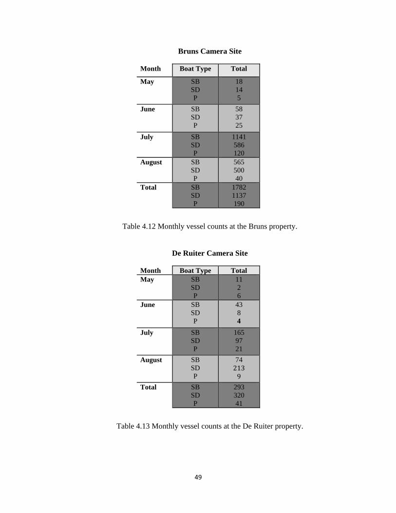
49
Bruns Camera Site
Month Boat Type Total
May SB SD P
18 14 5
June SB SD P
58 37 25
July SB SD P
1141 586 120
August SB SD P
565 500 40
Total SB SD P
1782 1137 190
Table 4.12 Monthly vessel counts at the Bruns property.
De Ruiter Camera Site
Month Boat Type Total May SB
SD P
11 2 6
June SB SD P
43 8 4
July SB SD P
165 97 21
August SB SD P
74 2139
Total SB SD P
293 320 41
Table 4.13 Monthly vessel counts at the De Ruiter property.
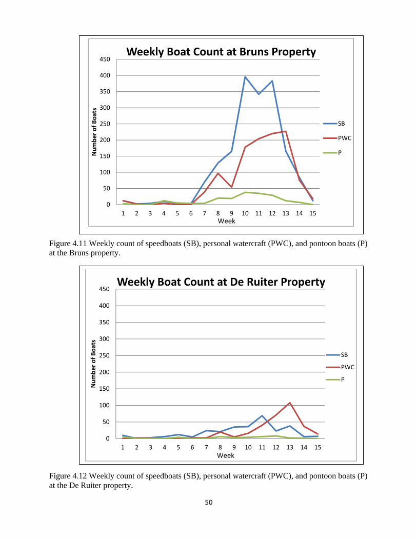
50
Figure 4.11 Weekly count of speedboats (SB), personal watercraft (PWC), and pontoon boats (P) at the Bruns property.
Figure 4.12 Weekly count of speedboats (SB), personal watercraft (PWC), and pontoon boats (P) at the De Ruiter property.
0
50
100
150
200
250
300
350
400
450
1 2 3 4 5 6 7 8 9 10 11 12 13 14 15
Number of Boats
Weekly Boat Count at Bruns Property
SB
PWC
P
Week
0
50
100
150
200
250
300
350
400
450
1 2 3 4 5 6 7 8 9 10 11 12 13 14 15
Number of Boats
Weekly Boat Count at De Ruiter Property
SB
PWC
P
Week
51
The camera images also reveal a great deal of information on boater behaviour. For
example, it became evident that on certain days, a large proportion of boat passages is due to
only one or two of the same boats that make multiple passages. For example, at the De Ruiter
site on July 20 the same boat passed by twelve times, which accounts for more than 60% of the
total speed boat traffic on that day. Similar patterns were observed at the Bruns site where it is
typical for a group of people to spend the day water skiing and taking turns on the skis. The river
reach by the Bruns site provides an especially quiet and desirable wave-free environment for
slalom-style skiing. In the late summer, both sites see an increase in the relative proportion of
PWCs, and at the De Ruiter site the number of PWCs is 3-6 times greater than speed boats. This
is likely due to low water depths that prevent the majority of boats from travelling along the
river.
Intensive Boat-Wake Experiments (August 2-3, 2013)
Hydrodynamic Data
The hydrodynamic data provide insight into the wave characteristics of boat wakes
generated by different watercraft. On the Lower Shuswap River, there are effectively only three
types of vessel that account for the vast majority of traffic: (1) Personal Water Craft (Figure
4.13); (2) Speed Boats (Figure 4.14); and (3) Pontoon Boats (Figure 4.15). Hydrodynamic data
associated with these three classes of vessel can be used to derive or estimate certain parameters
such as wave height, orbital velocity in the onshore-offshore and downstream directions, and
suspended sediment concentration. Although it has proven difficult to attribute a precise value
of bank erosion to single vessel passages (see Bauer et al., 2002 for discussion), these
hydrodynamic parameters facilitate an understanding of which vessels (hull type, speed, distance
to bank) likely contribute a greater or lesser amount to the bank erosion problem. In this section
we provide some preliminary data on common vessel types and their hydrodynamic signatures.
Note that for this report, the signals from the pressure transducers and electromagnetic current
meters were converted from raw analogue voltages to actual hydrodynamic parameters (water
depth and current velocity, respectively) using calibration equations that were provided by the
manufacturer or custom generated in the laboratory. Unfortunately at the time of writing, robust
calibration curves for the turbidity meters had not yet been generated, and the results are
52
therefore reported only in raw voltages. Nevertheless, signal response for these optical back-
scatterance sensors is linear, so the voltage data provide a fairly accurate (albeit relative) sense of
the data trends. The wave height and orbital velocity signals were not corrected for depth
attenuation, which implies that the reported values are conservative estimates of expected values
that might be larger by 1-10%.
A single personal watercraft (PWC) passage generates a maximum wave height on the
order of only a few centimetres (e.g., Figure 4.16). The explanation lies in the fact that PWC are
of very small displacement and the hull is designed for speed. Thus when a PWC moves at
planing speed, only a small amount of the hull is in the water thereby greatly reducing frictional
resistance. Clearly, larger PWCs generate larger wakes, and often these bigger models can carry
two or three passengers, which adds to overall water displacement (and hence size of wave). The
passage of a single personal watercraft therefore has minimal impact on bank erosion and only a
minimal amount of sediment suspension occurs in conjunction with a PWC (Figure 4.17). The
downstream current reached a maximum velocity of 0.06 ms-1 for the personal watercraft (see
Figure 4.18), whereas the onshore current reached a maximum velocity of 0.03 ms-1 (see Figure
4.19). The downstream current is larger in this instance likely because of the angle of wave
approach relative to the instrument orientation, but ordinarily one would expect much larger on-
offshore velocities as the wave crest and trough propagate past the instrument.
The passage of a single speedboat moving at high speed (and not towing a water skier)
generated a maximum wave height of about 7 cm (see Figure 4.20), about twice that of the PWC.
In addition, the primary wave train lasts considerably longer and is sustained at a wave height in
excess of 5 cm for at least 20-30 seconds. Figure 4.21 shows that the speedboat wake generated
higher turbidity levels in the water column than the PWC (Figure 4.15) but there is no obvious
correlation with the primary waves in the wake packet and the overall values are relatively small.
The maximum orbital velocities were of the order of 0.12 ms-1 (Figures 4.22 and 4.23), which is
twice that of the PWC.
A pontoon boat passage generates a maximum wave height of about 6-7 cm (Figure
4.24), which is of the same order as the speedboat, and similar turbidity levels (Figure 4.25).
There appears to be a more immediate response to the primary waves in the wake packet with the
pontoon boat, which may be explained by the slightly larger orbital velocities associated with the
pontoon boat (Figure 4.26 and 4.17).
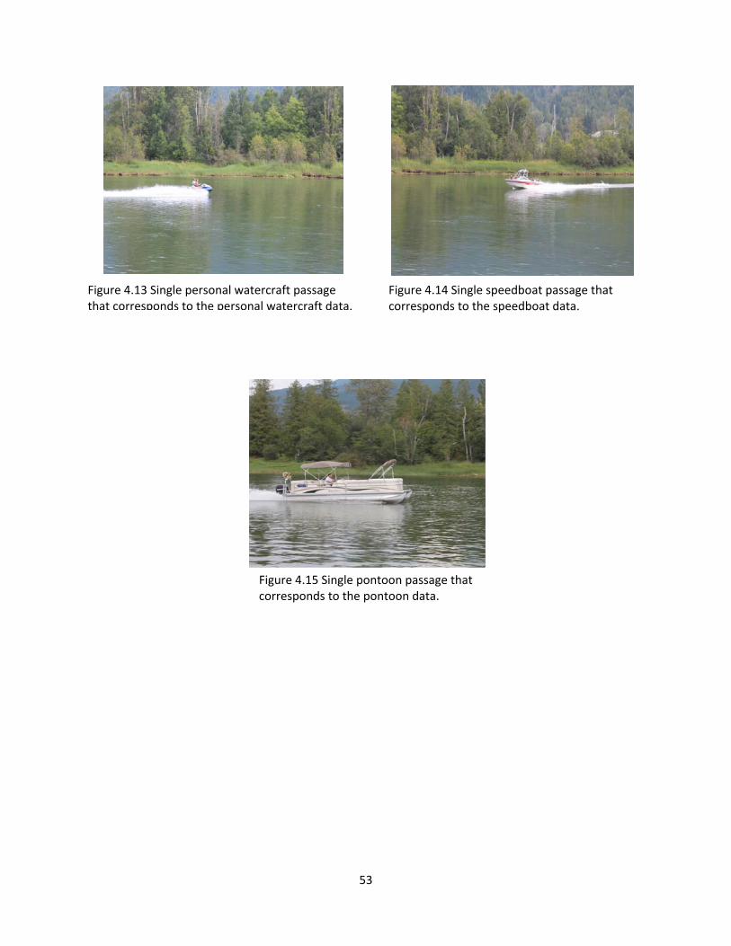
53
Figure 4.13 Single personal watercraft passage that corresponds to the personal watercraft data.
Figure 4.14 Single speedboat passage that corresponds to the speedboat data.
Figure 4.15 Single pontoon passage that corresponds to the pontoon data.
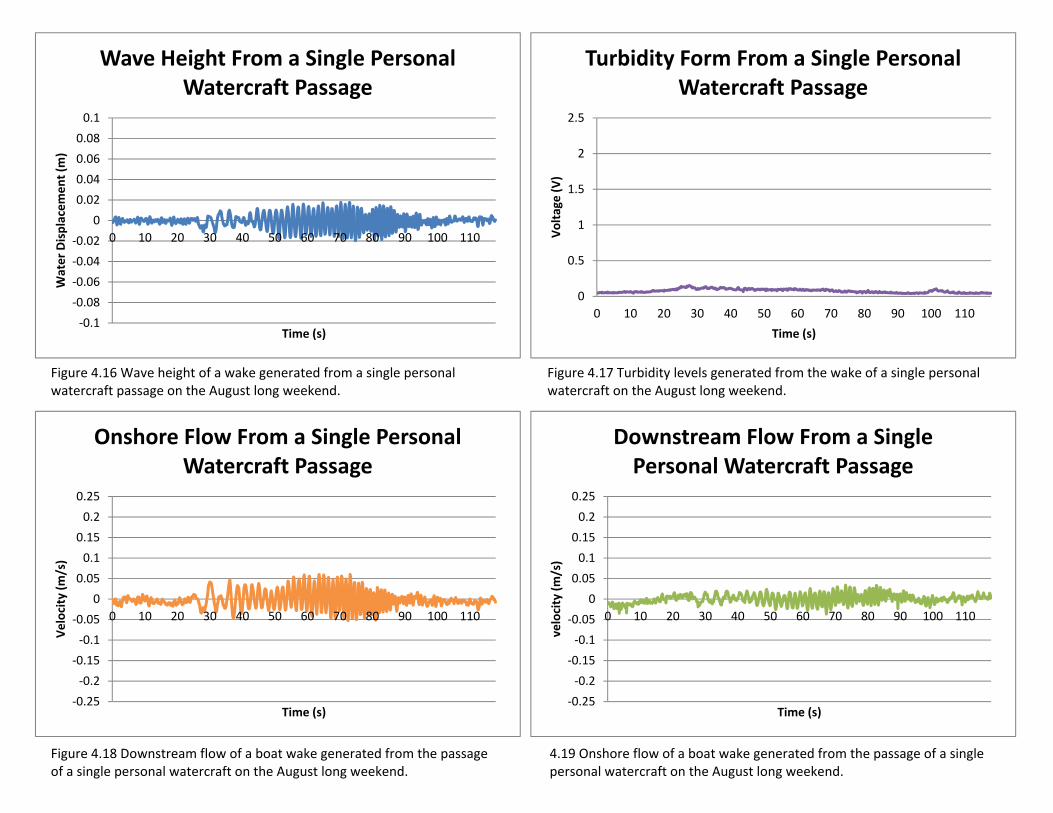
54
‐0.1
‐0.08
‐0.06
‐0.04
‐0.02
0
0.02
0.04
0.06
0.08
0.1
0 10 20 30 40 50 60 70 80 90 100 110
Water Displacement (m
)
Time (s)
Wave Height From a Single Personal Watercraft Passage
0
0.5
1
1.5
2
2.5
0 10 20 30 40 50 60 70 80 90 100 110
Voltage (V)
Time (s)
Turbidity Form From a Single Personal Watercraft Passage
‐0.25
‐0.2
‐0.15
‐0.1
‐0.05
0
0.05
0.1
0.15
0.2
0.25
0 10 20 30 40 50 60 70 80 90 100 110
Velocity (m/s)
Time (s)
Onshore Flow From a Single Personal Watercraft Passage
‐0.25
‐0.2
‐0.15
‐0.1
‐0.05
0
0.05
0.1
0.15
0.2
0.25
0 10 20 30 40 50 60 70 80 90 100 110
velocity (m/s)
Time (s)
Downstream Flow From a Single Personal Watercraft Passage
Figure 4.16 Wave height of a wake generated from a single personal watercraft passage on the August long weekend.
Figure 4.17 Turbidity levels generated from the wake of a single personal watercraft on the August long weekend.
Figure 4.18 Downstream flow of a boat wake generated from the passage of a single personal watercraft on the August long weekend.
4.19 Onshore flow of a boat wake generated from the passage of a single personal watercraft on the August long weekend.
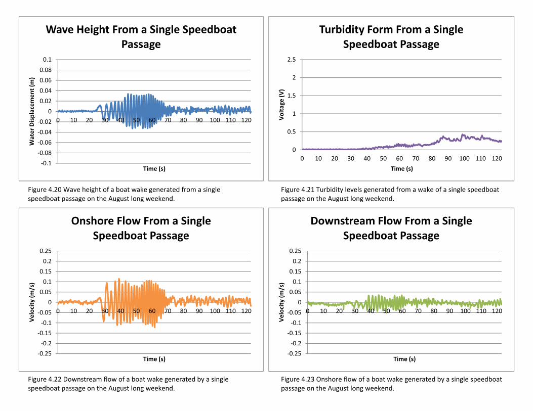
55
‐0.1
‐0.08
‐0.06
‐0.04
‐0.02
0
0.02
0.04
0.06
0.08
0.1
0 10 20 30 40 50 60 70 80 90 100 110 120
Water Displacement (m
)
Time (s)
Wave Height From a Single Speedboat Passage
0
0.5
1
1.5
2
2.5
0 10 20 30 40 50 60 70 80 90 100 110 120
Voltage (V)
Time (s)
Turbidity Form From a Single Speedboat Passage
‐0.25
‐0.2
‐0.15
‐0.1
‐0.05
0
0.05
0.1
0.15
0.2
0.25
0 10 20 30 40 50 60 70 80 90 100 110 120
Velocity (m/s)
Time (s)
Onshore Flow From a Single Speedboat Passage
‐0.25
‐0.2
‐0.15
‐0.1
‐0.05
0
0.05
0.1
0.15
0.2
0.25
0 10 20 30 40 50 60 70 80 90 100 110 120
Velocity (m/s)
Time (s)
Downstream Flow From a Single Speedboat Passage
Figure 4.20 Wave height of a boat wake generated from a single speedboat passage on the August long weekend.
Figure 4.21 Turbidity levels generated from a wake of a single speedboat passage on the August long weekend.
Figure 4.22 Downstream flow of a boat wake generated by a single speedboat passage on the August long weekend.
Figure 4.23 Onshore flow of a boat wake generated by a single speedboat passage on the August long weekend.
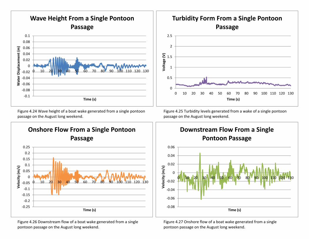
56
‐0.1
‐0.08
‐0.06
‐0.04
‐0.02
0
0.02
0.04
0.06
0.08
0.1
0 10 20 30 40 50 60 70 80 90 100 110 120 130
Water Displacement (m
)
Time (s)
Wave Height From a Single Pontoon Passage
0
0.5
1
1.5
2
2.5
0 10 20 30 40 50 60 70 80 90 100 110 120 130
Voltage (V)
Time (s)
Turbidity Form From a Single Pontoon Passage
‐0.25
‐0.2
‐0.15
‐0.1
‐0.05
0
0.05
0.1
0.15
0.2
0.25
0 10 20 30 40 50 60 70 80 90 100 110 120 130
Velocity (m/s)
Time (s)
Onshore Flow From a Single Pontoon Passage
‐0.08
‐0.06
‐0.04
‐0.02
0
0.02
0.04
0.06
0 10 20 30 40 50 60 70 80 90 100 110 120 130
Velocity (m/s)
Time (s)
Downstream Flow From a Single Pontoon Passage
Figure 4.24 Wave height of a boat wake generated from a single pontoon passage on the August long weekend.
Figure 4.25 Turbidity levels generated from a wake of a single pontoon passage on the August long weekend.
Figure 4.26 Downstream flow of a boat wake generated from a single pontoon passage on the August long weekend.
Figure 4.27 Onshore flow of a boat wake generated from a single pontoon passage on the August long weekend.
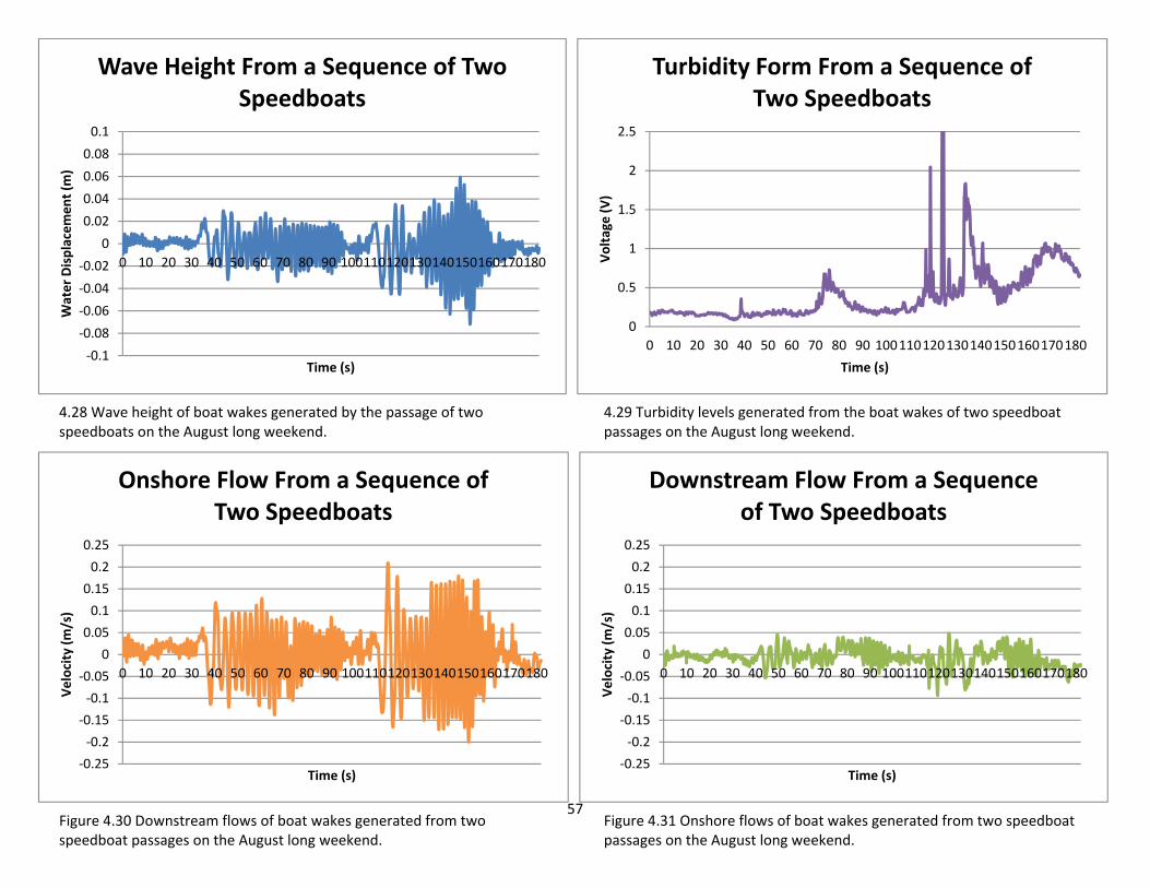
57
Figure 4.30 Downstream flows of boat wakes generated from two speedboat passages on the August long weekend.
Figure 4.31 Onshore flows of boat wakes generated from two speedboat passages on the August long weekend.
‐0.1
‐0.08
‐0.06
‐0.04
‐0.02
0
0.02
0.04
0.06
0.08
0.1
0 10 20 30 40 50 60 70 80 90 100110120130140150160170180
Water Displacement (m
)
Time (s)
Wave Height From a Sequence of Two Speedboats
0
0.5
1
1.5
2
2.5
0 10 20 30 40 50 60 70 80 90 100110120130140150160170180
Voltage (V)
Time (s)
Turbidity Form From a Sequence of Two Speedboats
‐0.25
‐0.2
‐0.15
‐0.1
‐0.05
0
0.05
0.1
0.15
0.2
0.25
0 10 20 30 40 50 60 70 80 90 100110120130140150160170180
Velocity (m/s)
Time (s)
Onshore Flow From a Sequence of Two Speedboats
‐0.25
‐0.2
‐0.15
‐0.1
‐0.05
0
0.05
0.1
0.15
0.2
0.25
0 10 20 30 40 50 60 70 80 90 100110120130140150160170180
Velocity (m/s)
Time (s)
Downstream Flow From a Sequence of Two Speedboats
4.29 Turbidity levels generated from the boat wakes of two speedboat passages on the August long weekend.
4.28 Wave height of boat wakes generated by the passage of two speedboats on the August long weekend.
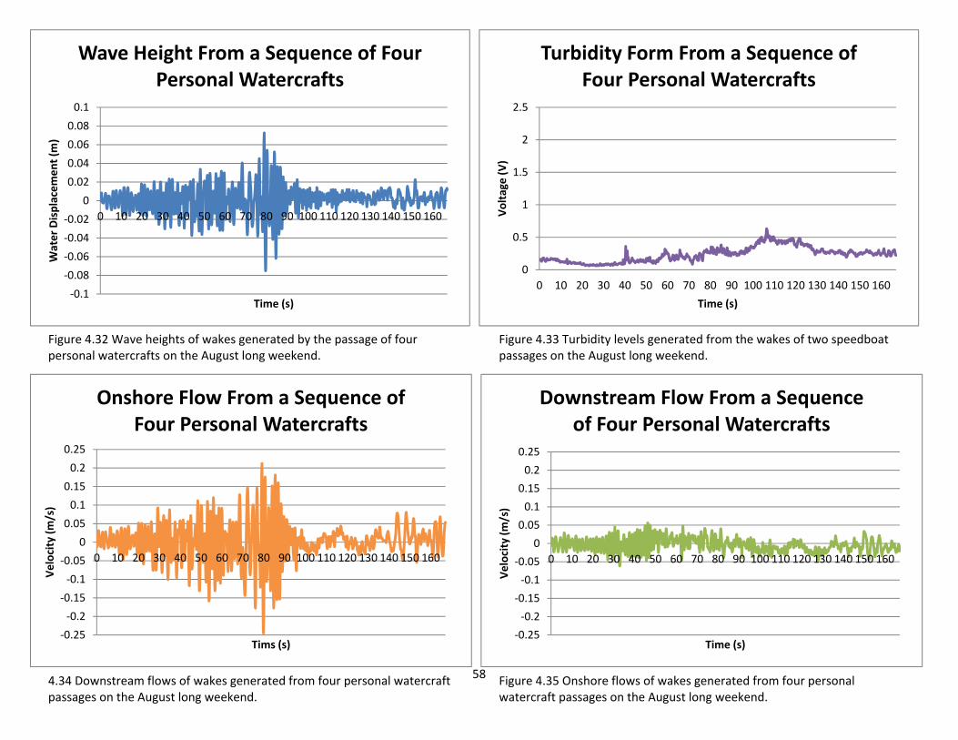
58
‐0.1
‐0.08
‐0.06
‐0.04
‐0.02
0
0.02
0.04
0.06
0.08
0.1
0 10 20 30 40 50 60 70 80 90 100 110 120 130 140 150 160
Water Displacement (m
)
Time (s)
Wave Height From a Sequence of Four Personal Watercrafts
0
0.5
1
1.5
2
2.5
0 10 20 30 40 50 60 70 80 90 100 110 120 130 140 150 160
Voltage (V)
Time (s)
Turbidity Form From a Sequence of Four Personal Watercrafts
‐0.25
‐0.2
‐0.15
‐0.1
‐0.05
0
0.05
0.1
0.15
0.2
0.25
0 10 20 30 40 50 60 70 80 90 100 110 120 130 140 150 160
Velocity (m/s)
Tims (s)
Onshore Flow From a Sequence of Four Personal Watercrafts
‐0.25
‐0.2
‐0.15
‐0.1
‐0.05
0
0.05
0.1
0.15
0.2
0.25
0 10 20 30 40 50 60 70 80 90 100 110 120 130 140 150 160
Velocity (m/s)
Time (s)
Downstream Flow From a Sequence of Four Personal Watercrafts
Figure 4.32 Wave heights of wakes generated by the passage of four personal watercrafts on the August long weekend.
Figure 4.33 Turbidity levels generated from the wakes of two speedboat passages on the August long weekend.
4.34 Downstream flows of wakes generated from four personal watercraft passages on the August long weekend.
Figure 4.35 Onshore flows of wakes generated from four personal watercraft passages on the August long weekend.
59
Often, multiple vessels accompany each other or pass in opposite directions at a
particular location, and the impact of such events tends to be more pronounced than the passage
of an isolated vessel. Figure 4.28 provides an example of the passage of two speedboats in close
proximity, which generated a maximum wave height of 12-13 cm after the second vessel passed
by. Figure 4.29 demonstrates that when the second speedboat passed by, the sediment that was
already in suspension due to the first vessel remains agitated while additional sediment is added
to the water column thereby increasing the overall turbidity levels. This is consistent with the
maximum orbital velocities in excess of about 0.21 ms-1 (Figures 2.30 and 2.31). It is not known
whether these multiple boat passage events actually strip more sediment from the bank than a
single passage, as opposed to simply agitating available sediment more thoroughly, but the
former seems likely. Indeed, this is consistent with observations elsewhere (Bauer et al., 2002).
Another example of multiple vessel passages is provided by an instance when four
personal watercraft passed by the site in a large group. This event generated a maximum wave
height of about 14 cm subsequent to the fourth PWC passage (see Figure 4.32), and Figure 4.33
clearly demonstrates that such events generate much more turbidity than the passage of a single
personal watercraft. Nevertheless, the turbidity levels are smaller than those due to the passage
of two speedboats. Maximum orbital velocities were about 0.2-0.25 ms-1 (Figures 4.34 and
4.35), which is well in excess of what was measured after the passage of a single PWC.
These data demonstrate how complex the problem of bank erosion due to boat wakes is.
Not only is sediment suspension related to wave energy in non-linear fashion, but the nature of
the wave packet differs from vessel to vessel. Moreover, when boats pass in rapid succession,
the water column becomes agitated in ways that seem chaotic in comparison to single vessel
passages, and the impact on turbidity levels is more pronounced.
Micro-Erosion Pins
A profile of micro-erosion pins was installed for the two-day period (August 2 to 3)
during the hydrodynamic experiments to measure more precisely the amount of erosion or
accretion that might occur in response to the number of boats that passed by the site. The micro-
erosion pins provide greater resolution and precision than the standard erosion pins made of re-
bar because they are smaller and narrower, thereby having a lesser impact on the flow dynamics

60
near the pins. Standard four-inch galvanized nails were installed along a profile line at 10 cm
increments beginning at the lower cut bank and extending across the flat sandy apron into
approximately 0.2 water depth (horizontal distance of about 2 m). The majority of the pins were
installed on August 2, but due to high turbidity levels it proved impossible to install pins in the
submerged portion of the profile. On August 3, the profile line was extended farther offshore
early in the morning before boating traffic had the opportunity to stir up sediments. As an aside,
this increase in the background turbidity levels in late morning after a significant number of
boats had passed the site was noted on both days. The water in the mornings is quite clear, but
visibility is greatly reduced from most of the late morning and into the late evening.
Figure 4.36 and Table 4.14 provide data from the micro-erosion pins on August 2
whereas Figure 4.37 and Table 4.15 provide data on August 3. On both days, there was virtually
no change in the upper parts of the profile. Although these upper pins were occasionally
inundated by the larger boat wakes, they did not truly experience the same energy levels as pins
lower in the profile that were consistently submerged in shallow water. The smaller erosion
values measured on August 2 are, in part, explained by the fact that the profile was not installed
until later in the day. The largest amount of erosion was measured on both days at the pins near
the water line and just below the water line, and on August 3 this erosion amounted to about 5
cm over the course of the day. A conservative estimate of the number of vessels that passed by
the site on August 2 is about 105, which yields an average erosion rate of about 0.5 mm per boat
passage for the pins with the most erosion. These are rather extreme erosion rates, and it should
be appreciated that they do not correspond to actual bank retreat. As noted earlier, this zone
below the true cut-bank on the apron had a deposit of silt from the flood waters of the spring
freshet, and now that the lower water stage provided direct access by waves, the fresh deposit
was being eroded. Because these materials are weak and unconsolidated, they are easily eroded
by any hydrodynamic disturbance. Tables 4.16 and 4.17 provide TorvaneTM assessments of the
material strength, which shows clearly that these silty materials are much weaker than the clay
bank materials higher up the profile.
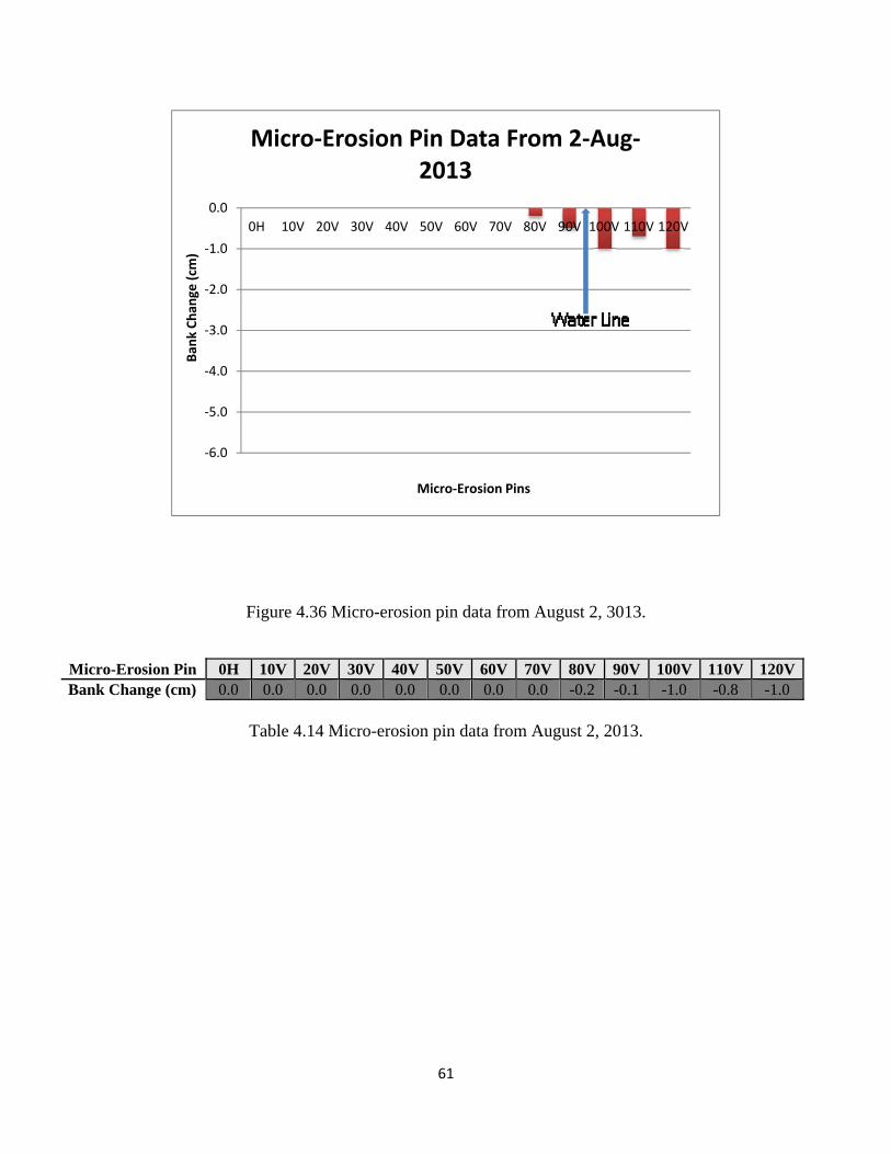
61
Figure 4.36 Micro-erosion pin data from August 2, 3013.
Table 4.14 Micro-erosion pin data from August 2, 2013.
Micro-Erosion Pin 0H 10V 20V 30V 40V 50V 60V 70V 80V 90V 100V 110V 120VBank Change (cm) 0.0 0.0 0.0 0.0 0.0 0.0 0.0 0.0 -0.2 -0.1 -1.0 -0.8 -1.0
‐6.0
‐5.0
‐4.0
‐3.0
‐2.0
‐1.0
0.0
0H 10V 20V 30V 40V 50V 60V 70V 80V 90V 100V 110V 120V
Ban
k Chan
ge (cm
)
Micro‐Erosion Pins
Micro‐Erosion Pin Data From 2‐Aug‐2013
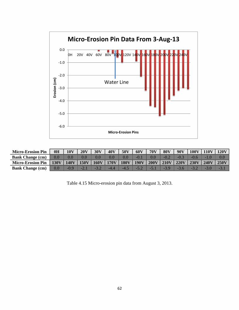
62
Figure 4.37 Micro-erosion pin data from August 3, 2013.
Table 4.15 Micro-erosion pin data from August 3, 2013.
Micro-Erosion Pin 0H 10V 20V 30V 40V 50V 60V 70V 80V 90V 100V 110V 120VBank Change (cm) 0.0 0.0 0.0 0.0 0.0 0.0 -0.1 0.0 -0.2 -0.3 -0.6 -1.0 0.0 Micro-Erosion Pin 130V 140V 150V 160V 170V 180V 190V 200V 210V 220V 230V 240V 250VBank Change (cm) 0.0 -0.9 -2.1 -3.2 -4.4 -4.5 -5.2 -5.1 -3.9 -3.6 -3.2 -3.0 -3.1
‐6.0
‐5.0
‐4.0
‐3.0
‐2.0
‐1.0
0.0
0H 20V 40V 60V 80V 100V 120V 140V 160V 180V 200V 220V 240VErosion (cm
)
Micro‐Erosion Pins
Micro‐Erosion Pin Data From 3‐Aug‐13
Water Line
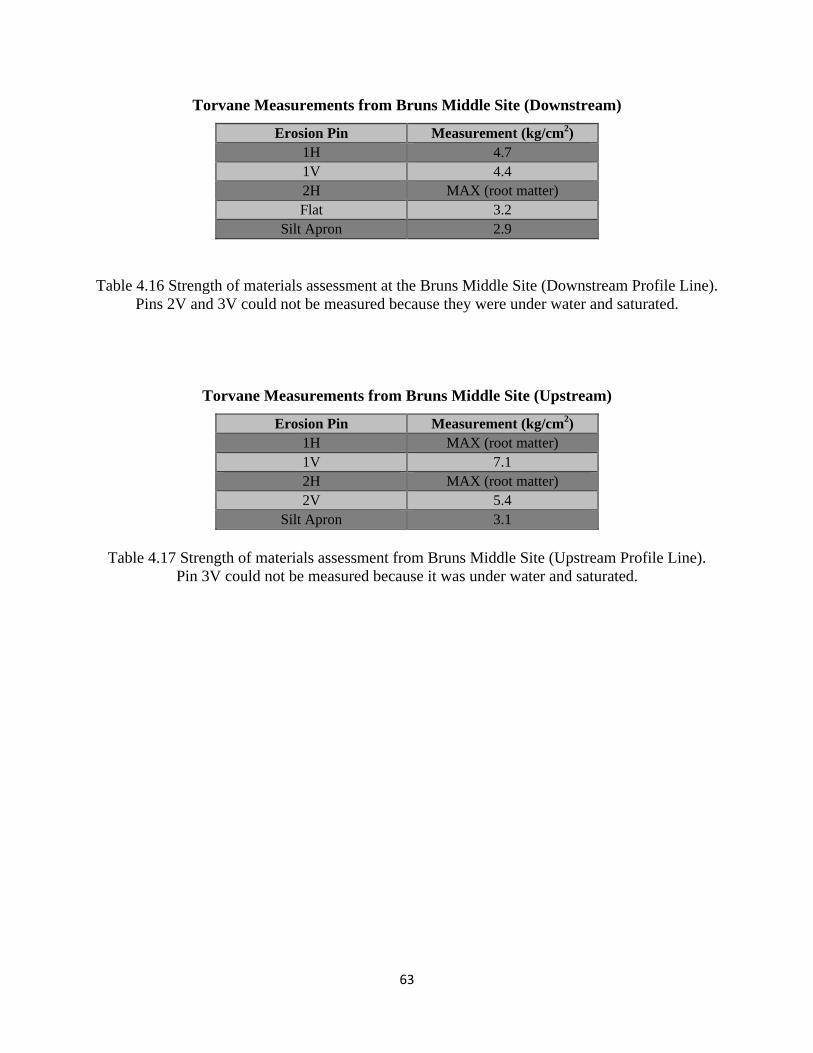
63
Torvane Measurements from Bruns Middle Site (Downstream)
Erosion Pin Measurement (kg/cm2) 1H 4.7 1V 4.4 2H MAX (root matter) Flat 3.2
Silt Apron 2.9
Table 4.16 Strength of materials assessment at the Bruns Middle Site (Downstream Profile Line). Pins 2V and 3V could not be measured because they were under water and saturated.
Torvane Measurements from Bruns Middle Site (Upstream)
Erosion Pin Measurement (kg/cm2) 1H MAX (root matter) 1V 7.1 2H MAX (root matter) 2V 5.4
Silt Apron 3.1
Table 4.17 Strength of materials assessment from Bruns Middle Site (Upstream Profile Line).
Pin 3V could not be measured because it was under water and saturated.
64
5
CONCLUSION
A project to quantify the rate of bank erosion along the Lower Shuswap River with
special focus on the relative importance of recreational boat traffic leads to the following
conclusions:
The peak boating period on the Shuswap River begins on the July long weekend and ends
mid-August. The highest daily average of boats occurs in the month of July. May and
June are typically too cold for intense boating activity and the river stage is still too high
(and discharge too large) to make recreational boating comfortable for most people. By
mid August the river stage is quite low, leading to dangerous boating conditions on the
river due to shallow waters and sandy shoals.
Weekend days typically have the most intense boat traffic, although this can be weather
dependent. The August long weekend is the busiest of the year on the Shuswap River.
On many days, a large portion of boat traffic is attributable to only a few boats that pass
through the same river reach multiple times, usually in the context of water skiing or
wake boarding. It seems reasonable to assume that these boaters are local stakeholders
who are familiar with these waters and who know where the significant hazards are
located. This suggests an avenue for public education and outreach regarding the impacts
of boats on bank erosion.
River reaches that are lower on the river and closer to amenities (e.g., cabins, boat
launches, and docks) on Mara Lake are subject to greater boat traffic (e.g., the Bruns
property). River reaches farther upstream (e.g., De Ruiter property) see less intense boat
traffic and a greater proportion of PWCs rather than speedboats, especially in August.
The limited data from the pin-erosion profile lines suggest that the most significant bank
erosion occurs during the spring freshet. This is largely because the uppermost portions
of the banks are inundated during the high-flow period, whereas at low flows (when
boating is most active) only the lowermost portions of the bank are subject to
65
hydrodynamic forces. The data set is not extensive enough to provide total confidence in
this conclusion.
Some locations along the river experience less erosion than other areas, and typically this
is due to: (a) thick vegetation cover; (b) very cohesive muddy bank materials with
extensive root mats that provide resistance to erosion; (c) protective barriers such as mid-
channel islands; (d) planform geometry of the river, specifically inside meander bends;
and (e) areas that are not exposed to significant boat traffic or other disturbances that
might intensify the hydrodynamic energy expended on the bank or otherwise weaken the
bank materials (e.g., burrowing animals). Examples of specific sites that experience
lesser and greater erosion are the Cox ‘control’ site and the Konge site, respectively.
A single passage of a watercraft is less damaging than a sequence of passages.
Nevertheless, the damage due to watercraft passages is cumulative, and therefore a long-
term perspective on the importance of boat wakes must be adopted.
Speedboats generate the most turbidity and the largest wave heights, especially when
there is a sequence of speedboats. This is especially true when the speedboats are used
for water skiing and wake boarding because the speeds are slower and more water is
displaced by the vessel hull, thereby yielding larger waves.
The study seems to indicate that boat wakes do indeed contribute to the erosion problem on the
Lower Shuswap River, but the extent of their contribution remains difficult to quantify with any
degree of certainty. Natural causes of erosion, in particular the strong currents associated with
the spring freshet as well as the geotechnical loading on saturated banks during the early summer
drawdown (associated with declining limb of the annual hydrograph) clearly dominate the
erosive signal along many reaches of the river. The outside portions of meander bends or even
reaches where the thalweg favours one side of the channel are particularly susceptible to long-
term erosion by natural processes. Nevertheless, boat wakes may still play an important role by
eroding the material that has been deposited on the gently sloping apron that is adjacent to the
cut bank, including large slump blocks that recently calved off the bank into the water. In more
extreme cases, boat-wake waves may undermine the bank leading to further instability and
slumping. In order to assess these processes, a multi-year monitoring process should be initiated

66
because the geomorphic changes witnessed at a single site over 4 months is not adequate to
evaluate the sequence of events that yield long-term bank erosion along rivers.
67
6
BIBLIOGRAPHY
Ahmad, M. . F., Yusoff, M. M., Husain, M. L., Wan Nik, W. M. M., & Muzathik, A. M (n.d). An investigation of boat wakes wave energy: a case study of Kemaman River Estuary, 907-913. Retrieved from http://umt.edu.my
Asplund, T. R. (2000). The effects of motorized watercraft on aquatic ecosystems. Wisconsin Department of Natural Resources. Retrieved from http://roundthelake.com
Baldwin, D. S. (2008). Impacts of recreational boating on river bank stability: Wake characteristics of powered vessels. Report for the Murray Catchment Management Authority. Murray-Darling Freshwater Research Centre, Wodonga, Victoria. Retrieved from http://arrow.latrobe.edu.au
Barrick, L. S. (1984). Kenai riverbank erosion study. Alaska Department of Fish and Game, Division of Fisheries Rehabilitation, Enhancement and Development. Retrieved from http://adfg.state.ak.us
Bauer, B. O., Lorang, M. S., & Sherman, D. J. (2002). Estimating boat-wake-induced levee erosion using sediment suspension measurements. Journal of Waterway, Port, Coastal, and Ocean Engineering, 128(4), 152–162. doi:10.1061/(ASCE)0733-950X(2002)128:4(152)
Beachler, M. M., & Hill, D. F. (2003). Stirring up Trouble? Resuspension of bottom sediments by recreational watercraft. Lake and Reservoir Management, 19(1), 15–25.
Bell, A., Elsaesser, B., & Whittaker, T (n.d). Environmental impact of fast ferry wash in shallow water. Retrieved from http://qub.ac.uk
Bhowmik, N. G., & Adams, J. R. (1981). Resuspension and lateral movement of sediment by tow traffic on the upper Mississippi and Illinois rivers. State Water Survey Division, Illinois Institute of Natural Resources. Retrieved from http://isws.illinois.edu
Bhowmik, N. G., Demissie, M., & Guo, C.-Y. (1982). Waves generated by river traffic and wind on the Illinois and Mississippi Rivers. University of Illinois Water Resources Center. Retrieved from http://isws.illinois.edu
Bhowmik, N. G., Demissie, M., & Osakada, S. (1981). Waves and drawdown generated by river traffic on the Illinois and Mississippi Rivers. SWS Contract Report 271, Illinois Institute of Natural Resources, University of Illinois, Champaign. Retrieved from http://isws.illinois.edu
68
Bhowmik, N. G., Soong, T. W., Reichelt, W. F., & Seddik, N. M. L. (1991). Waves generated by recreational traffic on the Upper Mississippi River System. Illinois State Water Survey, Champaign, Research Report 117. Retrieved from http://isws.illinois.edu
Bishop, M. J. (2008). Displacement of epifauna from seagrass blades by boat wake. Journal of Experimental Marine Biology and Ecology, 354(1), 111–118. doi:10.1016/j.jembe.2007.10.013
Bonham, A. J. (1983). The management of wave-spending vegetation as bank protection against boat wash. Landscape Planning, 10(1), 15–30.
Boumans, R. M. J., Day, J. W., Kemp, G. P., & Kilgen, K. (1997). The effect of intertidal sediment fences on wetland surface elevation, wave energy and vegetation establishment in two Louisiana coastal marshes. Ecological Engineering, 9(1), 37–50. doi:10.1016/S0925-8574(97)00028-1
Bradbury, J. (2005). Revised wave wake criteria for vessel operation on the lower Gordon River. Unpublished Nature Conservation Branch Report, Tasmania Department of Primary Industry, Water & Environment. Retrieved from http://tas.gov.au
Bradbury, J., Cullen, P., Dixon, G., & Pemberton, M. (1995). Monitoring and management of streambank erosion and natural revegetation on the lower Gordon River, Tasmanian Wilderness World Heritage Area. Australia Environmental Management, 19(2), 259-272.
Brebner, A., Helwig, P. C., & Carruthers, J. (1966). Waves produced by ocean-going vessels: a laboratory and field study. Coastal Engineering Proceedings, 1(10), 455–465.
Das, M. M., & Johnson, J. W. (1970). Waves generated by large ships and small boats. Coastal Engineering Proceedings, 1(12), 2281–2286.
Dorava, J. M. (2001). Mitigating boatwake-induced erosion along the Kenai River, Alaska. Water Science and Application, 4, 217-226.
Dorava, J. M., & Moore, G. W. (1997). Effects of boatwakes on streambank erosion, Kenai River, Alaska. USGS Water-Resources Investigations Report, 84. Retrieved from http://ak.water.usgs.gov
Ellis, J. T., Sherman, D. J., & Bauer, B. O. (2006). Depth compensation for pressure transducer measurements of boat wakes. Journal of Coastal Research, SI 39 (Proceedings of the 8th International Coastal Symposium), 488–492.
Ellis, J. T., Sherman, D. J., Bauer, B. O., & Hart, J. (2002). Assessing the impact of an organic restoration structure on boat wake energy. Journal of Coastal Research, 265(36), 256–265.
Ercan, A., & Younis, B. A. (2009). Prediction of bank erosion in a reach of the Sacramento River and its mitigation with groynes. Water Resources Management, 23(15), 3121–3147.
69
Erirf, A., & Soomere, T. (2004). Influence of fast ship waves on the optical properties of sea water in Tallinn Bay, Baltic Sea. Proceedings of the Estonian Academy of Sciences, Biology and Ecology, 53(3), 161–178. Estonian Academy Publishers.
Fisheries and Oceans Canada (n.d.). Shoreline erosion caused by boat wake. Retrieved from http://marinfo.gc.ca
Fonseca, M. S., & Malhotra, A. (2012). Boat wakes and their influence on erosion in the Atlantic Intracoastal Waterway, North Carolina. NOAA Technical Memorandum NOS NCCOS # 143. 24p.
Garrad, P. . N., & Hey, R. D. (1987). Boat traffic, sediment resuspension and turbidity in a broadland river. Journal of Hydrology, 95(3), 289–297.
Glamore, W. C. (2008). A decision support tool for assessing the impact of boat wake waves on inland waterways. International Conference on Coastal and Port Engineering in Developing Countries. 20p. Retrieved from http://pianc.org
Gourlay, T. (2011). Notes on shoreline erosion due to boat wakes and wind waves. Center for Marine Science and Technology Research Report 2011-16. Retrieved from http://cmst.curtin.edu.au
The Green Blue. (2008). Boat wash and bank erosion. Factsheet. Retrieved from http://thegreenblue.org.uk
Hagerty, D. J., Spoor, M. F., & Ullrich, C. R. (1981). Bank failure and erosion on the Ohio River. Engineering Geology, 17, 141–158.
Hamill, G., Johnston, H., and Stewart, D. (1999). Propeller wash scour near quay walls. Journal of Waterway, Port, Coastal, and Ocean Engineering, 125 (4). 170-175.
Hawes, K., Shleppe, J., & Jantz, B. (2011). Lower Shuswap River inventory and mapping. Ecoscape Environmental Consultants Ltd., Project File: 10-642. 72 pp. Retrieved from http://rdno.ca
Hill, D. F., Beachler, M. M., & Johnson, P. A. (2002). Hydrodynamic impacts of commercial jet-boating on the Chilkat River, Alaska. Alaska Department of Civil and Environmental Engineering, Pennsylvania State University. Retrieved from http://psu.edu
Hilton, J., & Phillips, G. L. (1982). The effect of boat activity on turbidity in a shallow broadland river. Journal of applied Ecology, 143-150.
Houser, C. (2011). Sediment resuspension by vessel-generated waves along the Savannah River, Georgia. Journal of Waterway, Port, Coastal and Ocean Engineering, 137(5), 246–257. doi:10.1061/(ASCE)WW.1943-5460.0000088.
70
Houser, C. (2010). Relative importance of vessel-generated and wind waves to salt marsh erosion in a restricted fetch environment. Journal of Coastal Research, 26(2), 230–240. doi:10.2112/08-1084.1
Hughes, Z., Fitzgerald, D. M., & Rosen, P. (2006). Assessing the impact of ferry boat wakes on shoreline erosion in Boston Harbor, Massachusetts (abs), Proceedings, International Conference of Coastal Engineering, ASCE, San Diego, CA.
Iowa Department of Natural Resources. (2006). How to control streambank erosion. Retrieved from http://ctre.iastate.edu
Jacobson, R. B., Femmer, S. R., & McKenney, R. A. (2001). Land-use changes and the physical habitat of streams: a review with emphasis on studies within the US Geological Survey Federal-State Cooperative Program (Vol. 1175). US Geological Survey.
Kirkegaard, J., Kofoed-Hansen, H., & Elfrink, B. (1998). Wake wash of high-speed craft in coastal areas. Coastal Engineering Proceedings, 1(26), 325–337.
Lawler, D. (2005). Towards the implementation of SEA-learning from EIA for water resources. implementing strategic environmental assessment (pp. 495–511). Berlin Heidelberg: Springer.
Lawler, D. (1994). Automated monitoring of bank erosion dynamics: new developments in the Photo-Electronic Erosion Pin (PEEP) system. Retrieved from http://comm-tec.com
Lawler, D. M., & Leeks, G. J. L. (1992). River bank erosion events on the Upper Severn detected by the photo-electronic erosion pin (PEEP) system. In Erosion and sediment transport monitoring programmes in river basins: Proceedings of the Oslo Symposium, August 1992 (pp. 95–106). Wallingford, UK: International Association for Hydrological Sciences.
Lawler, D. M., West, J. R., Couperthwaite, J. S., & Mitchell, S. B. (2001). Application of a novel automatic erosion and deposition monitoring system at a channel bank site on the Tidal River Trent, U.K. Estuarine, Coastal and Shelf Science, 53(2), 237–247. doi:10.1006/ecss.2001.0779
Macfarlane, G. J., Bose, N., & Duffy, J. T. (2012). Wave wake: Focus on vessel operations within sheltered waterways. In 2012 SNAME Annual Meeting & Exposition and Ship Product Symposium, 1, 27–48.
Macfarlane, G. J., Cox, G., & Bradbury, J. (2008). Bank erosion from small craft wave wake in sheltered waterways. The Transactions of the Royal Institution of Naval Architects-Part B, 150(B2), 33–48.
Maritime Navigation Commission. Working Group 41 & International Navigation Association. (2003). Guidelines for managing wake wash from high-speed vessels: Report of working group 41 of the Maritime Navigation Commission (Vol. 41). Retrieved from http://pianc.org

71
Maynord, S. T., Biedenharn, D. S., Fischenich, C. J., & Zufelt, J. E. (2008). Boat-wave-induced bank erosion on the Kenai River, Alaska. Retrieved from http://dtic.mil
Maynord, S. T, & Martin, S. K. (1996). Upper Mississippi River System Navigation/Sedimentation Study. Retrieved from http://dtic.mil
Mazumder, B. S., Bhowmik, N. G., & Soong, T. W. (1993). Turbulence in rivers due to navigation traffic. Journal of Hydraulic Engineering, 119(5), 581–597.
McConchie, J. A., & Toleman, I. E. J. (2003). Boat wakes as a cause of riverbank Erosion: a case study from the Waikato River, New Zealand. Journal of Hydrology, 42(2), 163–179.
Minnesota Department of Natural Resources. (1993). Mississippi River Bank Erosion and Boating. Factsheet. Retrieved from http://files.dnr.state.mn.us
Mussetter, R. A., Harvey, M. D., & Parkinson, S. (2007). Boat wake erosion of sand bars in Hells Canyon of the Snake River, Idaho and Oregon. World Environmental and Water Resources Congress 2007: Restoring Our Natural Habitat, 1–12.
NMMA Canada. (2013). The economic impact of recreational boating in Canada 2012. Retrieved from http://nmma.ca
Oregon State Marine Board. (2003). Watching Your Wake: A Boater’s Guide. Pamphlet. Retrieved from http://cms.oregon.gov
Osborne, P. D., & Boak, E. H. B. (1999). Sediment suspension and morphological response under vessel-generated wave groups: Torpedo Bay Auckland, New Zealand. Journal of Coastal Research, 15(2), 388–398.
Papanicolaou, A. N. (2001). Erosion of cohesive streambeds and banks. State of Washington Water Research Center Report WRR-08, Department of Civil and Environmental Engineering.
Parnell, K. E., & Kofoed-Hansen, H. (2001). Wakes from large high-speed ferries in confined coastal waters: Management approaches with examples from New Zealand and Denmark. Coastal Management, 29(3), 217–237.
Parnell, K. E., Mcdonald, S. . C., & Burke, A. E. (2007). Shoreline effects of vessel wakes, Marlborough Sounds, New Zealand. Journal of Coastal Research, 50, 502–506.
Pike Lake Community Associate. (2013). Watching your wake. Pamphlet. Retrieved from http://foca.on.ca
Scott, K. M. (1982). Erosion and sedimentation in the Kenai River, Alaska. US Government Printing Office. Retrieved from http://usgs.gov
72
Sheremet, A., Gravois, U., & Tian, M. (2012). Boat-wake statistics at Jensen Beach, Florida. Journal of Waterway, Port, Coastal, and Ocean Engineering. doi:10.1061/(ASCE)WW.1943-5460.0000182
Soomere, T. (2005). Fast ferry traffic as a qualitatively new forcing factor of environmental processes in non-tidal sea areas: a case study in Tallinn Bay, Baltic Sea. Environmental Fluid Mechanics, 5(4), 293-323.
Sorensen, R. M. (2004). Prediction of vessel-generated waves with reference to vessels Common to the Upper Mississippi River System. Retrieved from http://bts.gov
Strager, M. P., Anderson, J. T., Osbourne, J. D., & Fortney, R. (2011). A three-tiered framework to select, prioritize, and evaluate potential wetland and stream mitigation banking sites. Wetlands Ecology and Management, 19(1), 1–18. doi:10.1007/s11273-010-9194-y
Swett, R. A., Listowski, C., Fry, D., Boutelle, S., & Fann, D. (2009). A regional waterway management system for balancing recreational boating and resource protection. Environmental Management, 43(6), 962–971. doi:10.1007/s00267-008-9231-2
Torsvik, T., Dysthe, K., & Pedersen, G (n.d.). Waves generated by ships in shallow water at variable Froude numbers. Retrieved from http://researchgate.net
Wolter, C., & Arlinghaus, R. (2003). Navigation impacts on freshwater fish assemblages The ecological relevance of swimming performance. Reviews in Fish Biology and Fisheries, 13, 63–89.
Yousef, Y. A., Mclellon, W. M., & Zebuth, H. H. (1980). Changes in phosphorus concentrations due to mixing by motorboats in shallow lakes. Water Research, 14, 841–852.