er rahul sharma feeder protection
DESCRIPTION
Feeder Protection Power System - II (Switchgear and Protection)TRANSCRIPT

By: By: By: By: ErErErEr. . . . RahulRahulRahulRahul SharmaSharmaSharmaSharma
EE DEPARMENT SEMINAR April 23, 2012

•Overhead lines or cables which are used to distribute the load to the
customers. They interconnect the distribution substations
What is a Feeder? What is a Feeder? What is a Feeder? What is a Feeder?
•This is an electrical supply line, either overhead or underground,
which runs from the substation, through various paths, ending with the
transformers. It is a distribution circuit, usually less than 69,000 volts,
which carries power from the substation. with theloads.

• The modern age has come to depend heavily upon continuous and
reliable availability 0f electricity and a high quality of electricity too.
Computer and telecommunication networks, railway networks,
banking and continuous power industries are a few applications that
just cannot function without highly reliable power source.
Why Protection Is Important? Why Protection Is Important? Why Protection Is Important? Why Protection Is Important?
just cannot function without highly reliable power source.
•No power system cannot be designed in such a way that they would
never fail. So, protection is required for proper working.
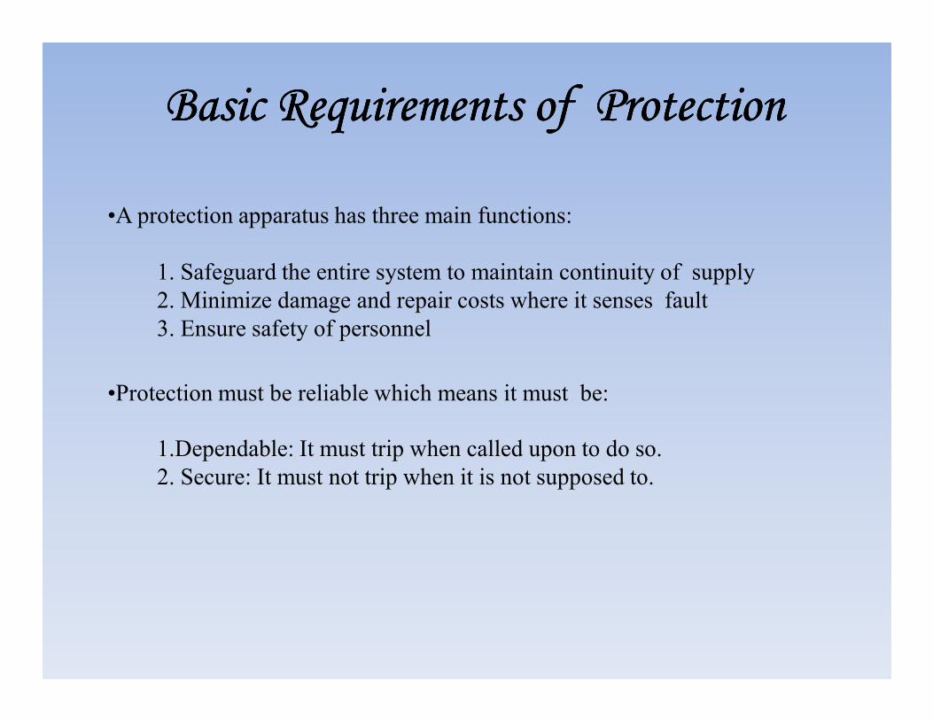
1. Safeguard the entire system to maintain continuity of supply
2. Minimize damage and repair costs where it senses fault
3. Ensure safety of personnel
Basic Requirements of Protection Basic Requirements of Protection Basic Requirements of Protection Basic Requirements of Protection
•A protection apparatus has three main functions:
1.Dependable: It must trip when called upon to do so.
2. Secure: It must not trip when it is not supposed to.
•Protection must be reliable which means it must be:

•These requirements are necessary for early detection and localization of
faults and for prompt removal of faulty equipment from service.
•Selectivity: To detect and isolate the faulty item only.
•Stability: To leave all healthy circuits intact to ensure continuity or supply.
Basic Requirements of Protection Basic Requirements of Protection Basic Requirements of Protection Basic Requirements of Protection
•Stability: To leave all healthy circuits intact to ensure continuity or supply.
• Sensitivity: To detect even the smallest fault, current or system
abnormalities and operate correctly at its setting before the fault causes
irreparable damage.
• Speed: To operate speedily when it is called upon to do so, thereby
minimizing damage to the surroundings and ensuring safety to personnel.

•A fault is defined as defect in electrical systems due to which current is
directed away from its intended path.
What Is Fault? What Is Fault? What Is Fault? What Is Fault?
•It is not practical to design and build electrical equipment or networks to
eliminate the possibility of failure in service. It is therefore an everyday
fact that different types of faults occur on electrical systems, however
infrequently, and at random locations.

•Faults can be broadly classified into two main areas which have
been designated as
•Active faults
Classification of faults Classification of faults Classification of faults Classification of faults
•Active faults
•Passive faults

•The ‘active’ fault is when actual current flows from one phase conductor to
another (phase-to-phase), or alternatively from one phase conductor to earth.
•This type of fault can also be further classified into two areas
• Solid Fault
Active Faults Active Faults Active Faults Active Faults
• Solid Fault
• Incipient Fault

•The solid fault occurs as a result of an immediate complete breakdown of
insulation as would happen.
•In these circumstances the fault current would be very high resulting in an
electrical explosion.
Solid Faults Solid Faults Solid Faults Solid Faults
•This type of fault must be cleared as quickly as possible, otherwise there
will be:
–Increased damage at fault location
–Danger of igniting combustible gas in hazardous areas
–Increased probability of faults spreading to healthy phases

•The incipient fault is a fault that starts as a small thing and gets developed
into catastrophic failure.
•Some partial discharge in a void in the insulation over an extended period
can burn away adjacent insulation, eventually spreading further and
Incipient Fault Incipient Fault Incipient Fault Incipient Fault
developing into a
‘solid’ fault.

•Passive faults are not real faults in the true sense of the word, but are
rather conditions that are stressing the system beyond its design capacity,
so that ultimately active faults will occur. Typical examples are:
•Overloading leading to over heating of insulation
•Overvoltage
Passive Faults Passive Faults Passive Faults Passive Faults
•Overvoltage
•Under frequency
•Power swings
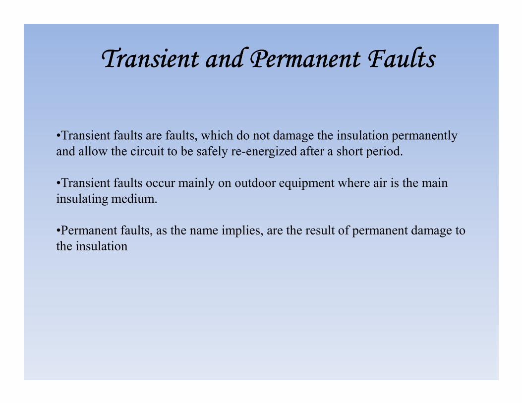
•Transient faults are faults, which do not damage the insulation permanently
and allow the circuit to be safely re-energized after a short period.
•Transient faults occur mainly on outdoor equipment where air is the main
insulating medium.
Transient and Permanent Faults Transient and Permanent Faults Transient and Permanent Faults Transient and Permanent Faults
insulating medium.
•Permanent faults, as the name implies, are the result of permanent damage to
the insulation

•A symmetrical fault is a balanced fault with the sinusoidal waves being
equal about their axes, and represents a steady- state condition.
•An asymmetrical fault displays a DC offset, transient in nature and
Symmetric and Asymmetric Faults Symmetric and Asymmetric Faults Symmetric and Asymmetric Faults Symmetric and Asymmetric Faults
•An asymmetrical fault displays a DC offset, transient in nature and
decaying to the steady state of the symmetrical fault after a period of time

Basic Fault Clearing Mechanism Basic Fault Clearing Mechanism Basic Fault Clearing Mechanism Basic Fault Clearing Mechanism
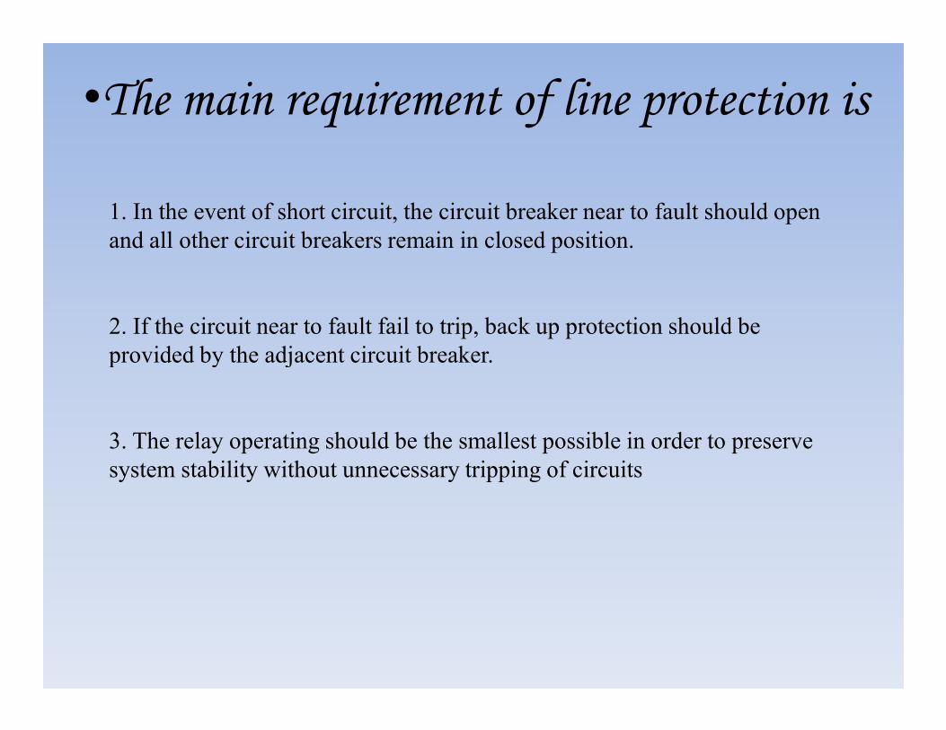
1. In the event of short circuit, the circuit breaker near to fault should open
and all other circuit breakers remain in closed position.
2. If the circuit near to fault fail to trip, back up protection should be
provided by the adjacent circuit breaker.
•The main requirement of line protection is
provided by the adjacent circuit breaker.
3. The relay operating should be the smallest possible in order to preserve
system stability without unnecessary tripping of circuits

•The need to analyze protection schemes has resulted in the development
of protection coordination programs.
Protection schemes can be divided into two major groupings:
Types of protection Types of protection Types of protection Types of protection
•Unit schemes
•Non-unit schemes

•Unit type schemes protect a specific area of the system, i.e., a transformer,
transmission line, generator or busbar.
•The most obvious example of unit protection schemes is based on Kerchief’s
current law – the sum of the currents entering an area of the system must be
zero.
Unit Type Protection Unit Type Protection Unit Type Protection Unit Type Protection
•Any deviation from this must indicate an abnormal current path.
•In these schemes, the effects of any disturbance or operating condition
outside the area of interest are totally ignored and the protection must be
designed to be stable above the maximum possible fault current that could
flow through the protected area

•The non-unit schemes, while also intended to protect specific areas, have no
fixed boundaries.
•As well as protecting their own designated areas, the protective zones can
overlap into other areas.
•While this can be very beneficial for backup purposes, there can be a
Non unit type protection Non unit type protection Non unit type protection Non unit type protection
•While this can be very beneficial for backup purposes, there can be a
tendency for too great an area to be isolated if a fault is detected by different
non unit schemes.
•The most simple of these schemes measures current and incorporates an
inverse time characteristic into the protection operation to allow protection
nearer to the fault to operate first.

Non unit type protection Non unit type protection Non unit type protection Non unit type protection Non unit type protection Non unit type protection Non unit type protection Non unit type protection

•The non unit type protection system includes following schemes:
–Time graded over current protection
–Current graded over current protection
–Distance or Impedance Protection
Non unit type protection Non unit type protection Non unit type protection Non unit type protection
–Distance or Impedance Protection

•This is the simplest of the ways to protect a line and therefore widely used.
•It owes its application from the fact that in the event of fault the current would
increase to a value several times greater than maximum load current.
Over current protection Over current protection Over current protection Over current protection
•It has a limitation that it can be applied only to simple and non costly equipments.


•The general practice is to employ a set of two or three over current relays
and a separate over current relay for single line to ground fault. Separate
earth fault relay provided makes earth fault protection faster and more
sensitive.
Earth fault protection Earth fault protection Earth fault protection Earth fault protection
•Earth fault current is always less than phase fault current in magnitude.
Therefore, relay connected for earth fault protection is different from those
for phase to phase fault protection.

Earth fault protection Earth fault protection Earth fault protection Earth fault protection

•This is a scheme of over current protection is one in which time discrimination
is incorporated. In other words, the time setting of the relays is so graded that
minimum possible part of system is isolated in the event of fault.
•We are to discuss the application of the time graded protection on
Time graded protection Time graded protection Time graded protection Time graded protection
•We are to discuss the application of the time graded protection on
–Radial feeder
–Parallel feeder
–Ring feeder

•The main characteristic of the radial feeder is that power can flow in one
direction only from generator to supply end of the load line.
•In radial feeder number of feeders can be connected in series and it is
desired that smallest part of the system should be off in the event of fault.
Protection of radial feeder Protection of radial feeder Protection of radial feeder Protection of radial feeder
•This is achieved by time graded protection.
•In this system time setting time setting of a relay is so adjusted that farther
the relay from the generating system lesser the time of operation


•The drawbacks of graded time lag over current protection are given below:
–The continuity in the supply cannot be maintained at the load end in the
event of fault.
–Time lag is provided which is not desirable in on short circuits.
Drawbacks of time graded protection on radial feeder Drawbacks of time graded protection on radial feeder Drawbacks of time graded protection on radial feeder Drawbacks of time graded protection on radial feeder
–Time lag is provided which is not desirable in on short circuits.
–It is difficult to co-ordinate and requires changes with the addition of load.
–It is not suitable for long distance transmission lines where rapid fault
clearance is necessary for stability.

•For important installations continuity of supply is a matter of vital importance
and at least two lines are used and connected parallel so as to share load.
•In the event of fault occurring the protecting device will select the faulty
feeder and isolate it while other instantly assumes increased load.
Protection of parallel feeder Protection of parallel feeder Protection of parallel feeder Protection of parallel feeder
feeder and isolate it while other instantly assumes increased load.
•The simplest method of obtaining such protection is providing time graded
over relays with inverse time characteristics at one end and reverse power
directional relay at the other end.


•The ring main is a system of inter connection between a series of power
stations by an alternate route.
•The direction of power flow can be changes at will.
Protection of ring main feeder
•The direction of power flow can be changes at will.

•In time graded protections IDMT (Inverse definite minimum time) relays are
used.
•As the name implies, it is a relay monitoring the current, and has inverse
characteristics with respect to the currents being monitored.
IDMT Relay IDMT Relay IDMT Relay IDMT Relay
This relay is without doubt one of the most popular relays used on medium-
and low- voltage systems for many years, and modern digital relays’
characteristics are still mainly based on the torque characteristic of this type of
relay.

IDMT relayIDMT relayIDMT relayIDMT relay
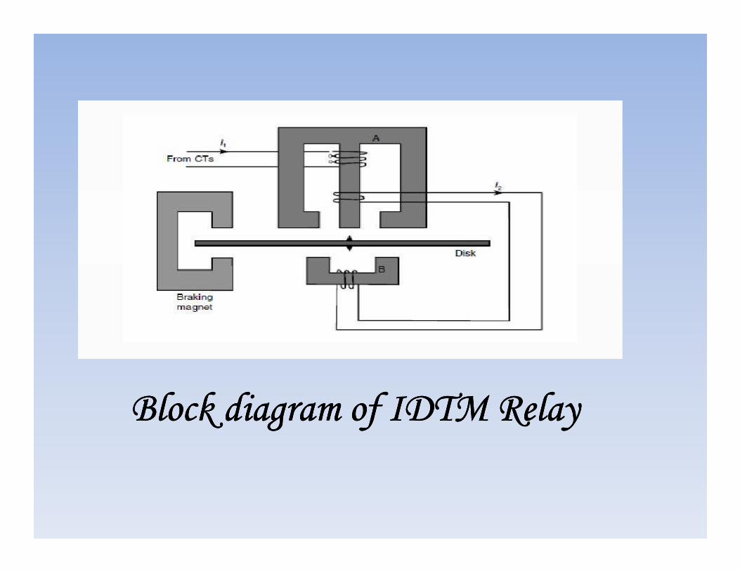
Block diagram of IDTM RelayBlock diagram of IDTM RelayBlock diagram of IDTM RelayBlock diagram of IDTM Relay

It can be seen that the operating time of an IDMTL relay is inversely
proportional to function of current, i.e. it has a long operating time
at low multiples of setting current and a relatively short operating
time at high multiples of setting current.

•It is an alternative to time graded protection and is used when the
impedance between two substations is sufficient.
•It is based on the fact that short circuit current along the length of protected
length of the circuit decreases with increase in distance between the supply
end and the fault point.
Current graded protection Current graded protection Current graded protection Current graded protection
end and the fault point.
•If the relays are set to operate at a progressively higher current towards the
supply end of the line then the drawback of the long time delays occurring
in the graded time lag system can be partially overcome.


Distance or impedance protection Distance or impedance protection Distance or impedance protection Distance or impedance protection
• A distance relay, as its name implies, has the ability to detect a fault
within a pre-set distance along a transmission line or power cable from its
location.
•Basic principle Basic principle Basic principle Basic principle
The basic principle of distance protection involves the division of the
voltage at the relaying point by the measured current.
The apparent impedance so calculated is compared with the reach point
impedance.
If the measured impedance is less than the reach point impedance, it is
assumed that a fault exists on the line between the relay and the reach
point.

BASIC PRINCIPLE OPERATION OF IMPEDANCE RELAYBASIC PRINCIPLE OPERATION OF IMPEDANCE RELAYBASIC PRINCIPLE OPERATION OF IMPEDANCE RELAYBASIC PRINCIPLE OPERATION OF IMPEDANCE RELAY

•The voltage is fed onto one coil to provide restraining torque, whilst the
current is fed to the other coil to provide the operating torque.
•Under healthy conditions, the voltage will be high (i.e. at full-rated level),
Balanced beam principle of impedance relay Balanced beam principle of impedance relay Balanced beam principle of impedance relay Balanced beam principle of impedance relay
whilst the current will be low thereby balancing the beam, and restraining it so
that the contacts remain open.
•Under fault conditions, the voltage collapses and the current increase
dramatically, causing the beam to unbalance and close the contacts.

Three stepped distance protection Three stepped distance protection Three stepped distance protection Three stepped distance protection
•Zone 1 •Zone 1 •Zone 1 •Zone 1
•First step of distance protection is set to reach up to 80 to 90% of
the length of the line section.
•This is instantaneous protection i.e. there is no intentional delay .
•second zone is requires in order to provide primary protection to
remaining 10 to 20% of the line and a cover up to 50% of the
next line section.
•The operating time of this zone is delayed so as to be selective
with zone 1.
•Zone 2 •Zone 2 •Zone 2 •Zone 2

•The third zone is provided with an intention to give full back up to
adjoining line section.
•It covers the line of the section, 100% of the next line section and
Three stepped distance protection Three stepped distance protection Three stepped distance protection Three stepped distance protection
•Zone 3 •Zone 3 •Zone 3 •Zone 3
•It covers the line of the section, 100% of the next line section and
reaches farther into the system.
•The motivation behind the extended reach of this step is to provide full
back up to the next line section.
•Its operating time is slightly more than that of zone 2.


Main or Unit Protection Main or Unit Protection Main or Unit Protection Main or Unit Protection Main or Unit Protection Main or Unit Protection Main or Unit Protection Main or Unit Protection

•The graded over current systems described earlier do not meet the protection
requirements of a power system.
•The grading is not possible to be achieved in long and thin networks and also it
can be noticed that grading of settings may lead to longer tripping times closer
to the sources, which are not always desired.
•These problems have given way to the concept of‘unit protection’ where the
Main or Unit Protection Main or Unit Protection Main or Unit Protection Main or Unit Protection
•These problems have given way to the concept of‘unit protection’ where the
circuits are divided into discrete sections without reference to the other sections.
•The power system is divided into discrete zones.
•Each zone is provided with relays and circuit breakers to allow for the detection
and isolation of its own internal faults.

•It is necessary to provide additional protection to ensure isolation of the fault
when the main protection fails to function correctly.
•This additional protection is referred to as‘back-up’ protection.
•The fault is outside the zones of the main protection and can only be cleared by
Back-up Protection
•The fault is outside the zones of the main protection and can only be cleared by
the separate back-up protection.
•Back-up protection must be time delayed to allow for the selective isolation of
the fault by the main or unit protection.

•Following types of main or unit protections are used in feeder networks
–Differential protection
–Carrier current protection using phase comparison
Types of Main Protection Types of Main Protection Types of Main Protection Types of Main Protection
–Carrier current protection using phase comparison
–Translay Y protection system

•The most positive and effective method of obtaining selectivity is the use
of differential protection. For less important installations, selectivity may
be obtained, at the expense of speed of operation, with time-graded
protection.
Methods of obtaining selectivity
•The principle of unit protection was initially established by Merz and
Price who were the creators of the fundamental differential protection
scheme.

•Differential protection, as its name implies, compares the currents entering
and leaving the protected zone and operates when the differential between
these currents exceeds a pre-determined magnitude.
This type of protection can be divided into two types, namely
Differential protection Differential protection Differential protection Differential protection
–Balanced current
–Balanced voltage

•The CTs are connected in series and the secondary current circulates
between them.
•The relay is connected across the midpoint thus the voltage across the
Balanced current Protection Balanced current Protection Balanced current Protection Balanced current Protection
relay is theoretically nil, therefore no current through the relay and hence
no operation for any faults outside the protected zone.
•Similarly under normal conditions the currents, leaving zone A and B
are equal, making the relay to be inactive by the current balance.

Differential protection using current balance
scheme (external fault conditions)

Differential protection and internal fault
conditions
•The current transformers are assumed identical and are assumed to
share the burden equally between the two ends.
•However, it is not always possible to have identical CTs and to have
the relay at a location equidistant from the two end CTs.
•It is a normal practice to add a resistor in series with the relay to
Balanced current Protection Balanced current Protection Balanced current Protection Balanced current Protection
•It is a normal practice to add a resistor in series with the relay to
balance the unbalance created by the unequal nature of burden between
the two end circuits.
•This resistor is named as ‘stabilizing resistance’.

McColl circulating current protection for single
phase
systems

•As the name implies, it is necessary to create a balanced voltage across the
relays in end A and end B under healthy and out-of-zone fault conditions.
•In this arrangement, the CTs are connected to oppose each other .
Balanced voltage system Balanced voltage system Balanced voltage system Balanced voltage system
•Voltages produced by the secondary currents are equal and opposite; thus
no currents flow in the pilots or relays, hence stable on through-fault
conditions. Under internal fault conditions relays will operate.

Balanced voltage system – external fault
(stable)

Balanced voltage system, internal fault
(operate)

•The system can be employed for the protection of single phase or 3-
phase feeders, transformer feeders and parallel feeders against both
earth and phase faults.
TranslayTranslayTranslayTranslay Y Protection system Y Protection system Y Protection system Y Protection system
•It works on the principle that current entering one end of the feeder at
any instant equals the current leaving the feeder.

Translay Y Protection system

•The capacitance currents do not effect the operation much.
•Only two pilot wires needed.
•The current transformers of normal designs are employed i.e. air core type
Advantages of Advantages of Advantages of Advantages of TranslayTranslayTranslayTranslay system system system system
•The current transformers of normal designs are employed i.e. air core type
•The pilot resistance do not effect the operation as the major part of power is
obtained from CTs for operation.

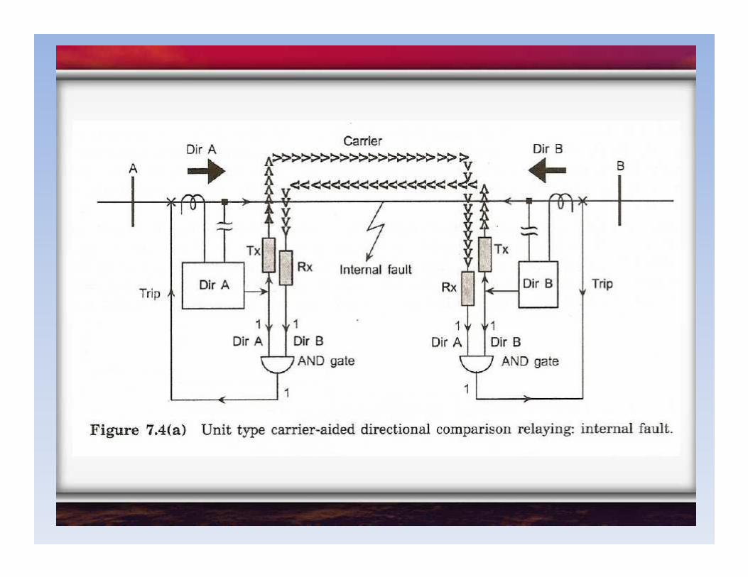
•In this type of relay we exploit the phase shift undergone by the current at
the end by which is nearest to the fault.
•The end which is far from the fault cannot discern any changes in the
phase of fault current and the closer end sees a sharp, almost 180˚ change in
the phase current.
Carrier current protection using phase comparison Carrier current protection using phase comparison Carrier current protection using phase comparison Carrier current protection using phase comparison
the phase current.
•Under normal conditions, load currents and external fault currents can be
arranged to be exactly out of phase but in case of internal faults the currents
become in phase.


•With the inherently selective forms of protection, apart from ensuring that
the relays do not operate incorrectly due to initial transients, no time delay is
necessary.
•Operating times for the protection, excluding the breaker tripping/clearing
time are generally of the following order:
Time taken to clear faults Time taken to clear faults Time taken to clear faults Time taken to clear faults
–Machine differential – few cycles
–Transformer differential – 10 cycles
–Switchgear (busbar) differential – 4 cycles
–Feeder differential – few cycles
•These operating times are practically independent of the magnitude of fault
current.

•Fast and selective
Unit protection is fast and selective. It will only trip the faulty item of plant,
thereby ensuring the elimination of any network disruptions.
•No time constraints
Time constraints imposed by the supply authorities do not become a major
Advantages of unit protection Advantages of unit protection Advantages of unit protection Advantages of unit protection
Time constraints imposed by the supply authorities do not become a major
problem anymore.
•Future expansion relatively easy
Any future expansion that may require another in-feed point can be handled
with relative ease without any change to the existing protection