epa10-us,canadadiagnosticmanual 0000003081...
TRANSCRIPT
DIAGNOSTIC
MANUAL
0000003081Aftertreatm
entSym
ptom-Based
Diagnostic
andInspection
Manual-M
axxForce®D
T,9and
10(EPA
10),MaxxForce
®11,13and
15(EPA
10)Revision
5EPA
10-U
S,C
anadaOctober2014
DIAGNOSTIC MANUAL
Aftertreatment Symptom-Based Diagnostic and Inspection Manual
MaxxForce® DT, 9 and 10 (EPA 10)MaxxForce® 11, 13 and 15 (EPA 10)
Navistar, Inc.2701 Navistar Drive, Lisle, IL 60532 USA
© 2014 Navistar, Inc. All rights reserved. All marks are trademarks of their respective owners.


TABLE OF CONTENTS
TABLE OF CONTENTS1. FOREWORD... . . . . . . . . . . . . . . . . . . . . . . . . . . . . . . . . . . . . . . . . . . . . . . . . . . . . . . . . . . . . . . . . . . . . . . . . . . . . . . . . . . . . . . . . . . . . . . . . . . . . . 1
2. SAFETY INFORMATION.. . . . . . . . . . . . . . . . . . . . . . . . . . . . . . . . . . . . . . . . . . . . . . . . . . . . . . . . . . . . . . . . . . . . . . . . . . . . . . . . . . . . . . . . . 2
3. MAXXFORCE® DT, 9 AND 10 AFTERTREATMENT SYSTEM DIAGNOSTICS.. . . . . . . . . . . . . . . . . . . . . . . . . . . 53.1. START DIAGNOSTICS HERE: ENGINE AND AFTERTREATMENT SYSTEM
OPERATIONAL CHECKS.. . . . . . . . . . . . . . . . . . . . . . . . . . . . . . . . . . . . . . . . . . . . . . . . . . . . . . . . . . . . . . . . . . . . . . . . . . . . . . . . 53.2. SYMPTOM 1 (MEDIUM DUTY): FREQUENT PARKED REGENS WITH NO ACTIVE
FAULT CODES (MORE THAN ONE PARKED REGEN PER DAY). . . . . . . . . . . . . . . . . . . . . . . . . . . . . . . . . . . 83.3. SYMPTOM 2 (MEDIUM DUTY): ENGINE NO START / STARTS AND STALLS.. . . . . . . . . . . . . . . . . . 173.4. SYMPTOM 3 (MEDIUM DUTY): SPN 3719 OR SPN 3936 ACTIVE ONLY OR
FREQUENT REGENS (MORE THAN ONE PARKED REGEN PER DAY). . . . . . . . . . . . . . . . . . . . . . . . . 243.5. SYMPTOM 4 (MEDIUM DUTY): SPN 3719 OR SPN 3936 AND OTHER ACTIVE FAULT
CODES.. . . . . . . . . . . . . . . . . . . . . . . . . . . . . . . . . . . . . . . . . . . . . . . . . . . . . . . . . . . . . . . . . . . . . . . . . . . . . . . . . . . . . . . . . . . . . . . . . . . . 343.6. SYMPTOM 5 (MEDIUM DUTY) : BLACK SMOKE.. . . . . . . . . . . . . . . . . . . . . . . . . . . . . . . . . . . . . . . . . . . . . . . . . . . 44
4. MAXXFORCE® DT, 9 AND 10 SERVICEMAXX™ SNAPSHOTS.. . . . . . . . . . . . . . . . . . . . . . . . . . . . . . . . . . . . . . . . . . 514.1. GRAPH 1: AIR MANAGEMENT SYSTEM TEST (GOOD). . . . . . . . . . . . . . . . . . . . . . . . . . . . . . . . . . . . . . . . . . . 514.2. GRAPH 2: AIR MANAGEMENT SYSTEM TEST (BAD).. . . . . . . . . . . . . . . . . . . . . . . . . . . . . . . . . . . . . . . . . . . . . 534.3. GRAPH 3: 0 TO 60 MPH TEST (ICP DESIRED AND ICP). . . . . . . . . . . . . . . . . . . . . . . . . . . . . . . . . . . . . . . . . . 544.4. GRAPH 4: 0 TO 60 MPH TEST (ENGINE SPEED, ENGINE LOAD, IMP, EBP, AND APP1). . . . 554.5. GRAPH 5: NORMAL EXHAUST GAS TEMPERATURES (EFFICIENT DOC AND
UNRESTRICTED AFI) . . . . . . . . . . . . . . . . . . . . . . . . . . . . . . . . . . . . . . . . . . . . . . . . . . . . . . . . . . . . . . . . . . . . . . . . . . . . . . . . . . . 574.6. GRAPH 6: ERRATIC EXHAUST GAS TEMPERATURES .. . . . . . . . . . . . . . . . . . . . . . . . . . . . . . . . . . . . . . . . . . 594.7. GRAPH 7: LOW EXHAUST GAS TEMPERATURES (RESTRICTED AFI). . . . . . . . . . . . . . . . . . . . . . . . . 604.8. SOOT LOAD LEVEL VS. EXHAUST GAS TARGET TEMPERATURE CHART. . . . . . . . . . . . . . . . . . . 62
5. AFTERTREATMENT SYSTEM OPERATION.. . . . . . . . . . . . . . . . . . . . . . . . . . . . . . . . . . . . . . . . . . . . . . . . . . . . . . . . . . . . . . . . 635.1. MAXXFORCE® DT, 9 AND 10 .. . . . . . . . . . . . . . . . . . . . . . . . . . . . . . . . . . . . . . . . . . . . . . . . . . . . . . . . . . . . . . . . . . . . . . . . . . 63
6. COMPONENT DESCRIPTIONS (THEORY OF OPERATION). . . . . . . . . . . . . . . . . . . . . . . . . . . . . . . . . . . . . . . . . . . . . . 666.1. MAXXFORCE® DT, 9 AND 10 .. . . . . . . . . . . . . . . . . . . . . . . . . . . . . . . . . . . . . . . . . . . . . . . . . . . . . . . . . . . . . . . . . . . . . . . . . . 66
7. AFTERTREATMENT SYSTEM FAULT CODES.. . . . . . . . . . . . . . . . . . . . . . . . . . . . . . . . . . . . . . . . . . . . . . . . . . . . . . . . . . . . . 757.1. MAXXFORCE® DT, 9 AND 10 (EPA 10). . . . . . . . . . . . . . . . . . . . . . . . . . . . . . . . . . . . . . . . . . . . . . . . . . . . . . . . . . . . . . . . 75
8. AFTERTREATMENT SYSTEM EVENT CHART.. . . . . . . . . . . . . . . . . . . . . . . . . . . . . . . . . . . . . . . . . . . . . . . . . . . . . . . . . . . . . 788.1. MAXXFORCE® DT, 9 AND 10.. . . . . . . . . . . . . . . . . . . . . . . . . . . . . . . . . . . . . . . . . . . . . . . . . . . . . . . . . . . . . . . . . . . . . . . . . . 78
9. MAXXFORCE® 11,13 AND 15 AFTERTREATMENT SYSTEM DIAGNOSTICS. . . . . . . . . . . . . . . . . . . . . . . . . . 799.1. START DIAGNOSTICS HERE: ENGINE AND AFTERTREATMENT SYSTEM
OPERATIONAL CHECKS.. . . . . . . . . . . . . . . . . . . . . . . . . . . . . . . . . . . . . . . . . . . . . . . . . . . . . . . . . . . . . . . . . . . . . . . . . . . . . . . 799.2. SYMPTOM 1 (HEAVY DUTY): FREQUENT PARKED REGENS WITH NO ACTIVE
FAULT CODES (MORE THAN ONE PARKED REGEN PER DAY). . . . . . . . . . . . . . . . . . . . . . . . . . . . . . . . . 839.3. SYMPTOM 2 (HEAVY DUTY): ENGINE NO START / STARTS AND STALLS.. . . . . . . . . . . . . . . . . . . . 919.4. SYMPTOM 3 (HEAVY DUTY): SPN 3719 ACTIVE ONLY OR FREQUENT REGENS
(MORE THAN ONE PARKED REGEN PER DAY). . . . . . . . . . . . . . . . . . . . . . . . . . . . . . . . . . . . . . . . . . . . . . . . . . . . 969.5. SYMPTOM 4 (HEAVY DUTY): SPN 3719 AND OTHER ACTIVE FAULT CODES .. . . . . . . . . . . . . 1049.6. SYMPTOM 5 (HEAVY DUTY): BLACK SMOKE .. . . . . . . . . . . . . . . . . . . . . . . . . . . . . . . . . . . . . . . . . . . . . . . . . . . . 113
i
TABLE OF CONTENTS
TABLE OF CONTENTS (CONT.)
10. MAXXFORCE® 11, 13 AND 15 SERVICEMAXX™ SNAPSHOTS.. . . . . . . . . . . . . . . . . . . . . . . . . . . . . . . . . . . . . . . . 12010.1. GRAPH 1: AIR MANAGEMENT SYSTEM TEST (GOOD). . . . . . . . . . . . . . . . . . . . . . . . . . . . . . . . . . . . . . . . . 12010.2. GRAPH 2: AIR MANAGEMENT SYSTEM TEST (BAD). . . . . . . . . . . . . . . . . . . . . . . . . . . . . . . . . . . . . . . . . . . . 12210.3. GRAPH 3: LUG DOWN TEST (ENGINE SPEED, FRP, AND FRPD). . . . . . . . . . . . . . . . . . . . . . . . . . . . . 12410.4. GRAPH 4: LUG DOWN TEST (ENGINE SPEED AND TC1TOP). . . . . . . . . . . . . . . . . . . . . . . . . . . . . . . . . 12610.5. GRAPH 5: LUG DOWN TEST (ENGINE SPEED, APP1, VEHICLE SPEED, AND IMP). . . . . . . . 12710.6. GRAPH 6: NORMAL EXHAUST GAS TEMPERATURES (EFFICIENT DOC AND
UNRESTRICTED AFI). . . . . . . . . . . . . . . . . . . . . . . . . . . . . . . . . . . . . . . . . . . . . . . . . . . . . . . . . . . . . . . . . . . . . . . . . . . . . . . . . . 12910.7. GRAPH 7: INVERTED EXHAUST GAS TEMPERATURES (INEFFICIENT DOC). . . . . . . . . . . . . . . 13110.8. GRAPH 8: LOW EXHAUST GAS TEMPERATURES (RESTRICTED AFI). . . . . . . . . . . . . . . . . . . . . . . 133
11. AFTERTREATMENT SYSTEM OPERATION.. . . . . . . . . . . . . . . . . . . . . . . . . . . . . . . . . . . . . . . . . . . . . . . . . . . . . . . . . . . . . . . 13511.1. MAXXFORCE® 11, 13 AND 15 .. . . . . . . . . . . . . . . . . . . . . . . . . . . . . . . . . . . . . . . . . . . . . . . . . . . . . . . . . . . . . . . . . . . . . . . 135
12. COMPONENT DESCRIPTIONS (THEORY OF OPERATION). . . . . . . . . . . . . . . . . . . . . . . . . . . . . . . . . . . . . . . . . . . . . 13812.1. MAXXFORCE® 11 AND 13 .. . . . . . . . . . . . . . . . . . . . . . . . . . . . . . . . . . . . . . . . . . . . . . . . . . . . . . . . . . . . . . . . . . . . . . . . . . . . 138
13. AFTERTREATMENT SYSTEM FAULT CODES.. . . . . . . . . . . . . . . . . . . . . . . . . . . . . . . . . . . . . . . . . . . . . . . . . . . . . . . . . . . . 14713.1. MAXXFORCE® 11, 13 AND 15.. . . . . . . . . . . . . . . . . . . . . . . . . . . . . . . . . . . . . . . . . . . . . . . . . . . . . . . . . . . . . . . . . . . . . . . . 147
14. AFTERTREATMENT SYSTEM EVENT CHART.. . . . . . . . . . . . . . . . . . . . . . . . . . . . . . . . . . . . . . . . . . . . . . . . . . . . . . . . . . . 15114.1. MAXXFORCE® 11, 13 AND 15.. . . . . . . . . . . . . . . . . . . . . . . . . . . . . . . . . . . . . . . . . . . . . . . . . . . . . . . . . . . . . . . . . . . . . . . . 151
15. REGEN INHIBITORS AND ENTRY CONDITIONS.. . . . . . . . . . . . . . . . . . . . . . . . . . . . . . . . . . . . . . . . . . . . . . . . . . . . . . . . . 15215.1. REGEN INHIBITORS.. . . . . . . . . . . . . . . . . . . . . . . . . . . . . . . . . . . . . . . . . . . . . . . . . . . . . . . . . . . . . . . . . . . . . . . . . . . . . . . . . . 15215.2. ENTRY CONDITIONS.. . . . . . . . . . . . . . . . . . . . . . . . . . . . . . . . . . . . . . . . . . . . . . . . . . . . . . . . . . . . . . . . . . . . . . . . . . . . . . . . . 156
16. DPF AND DOC REUSE GUIDELINES.. . . . . . . . . . . . . . . . . . . . . . . . . . . . . . . . . . . . . . . . . . . . . . . . . . . . . . . . . . . . . . . . . . . . . . 15916.1. MAXXFORCE® DT, 9, AND 10; MAXXFORCE® 11, 13 AND 15.. . . . . . . . . . . . . . . . . . . . . . . . . . . . . . . . . . . 159
16.1.1. Diesel Particulate Filter (DPF) Inlet - Clean. . . . . . . . . . . . . . . . . . . . . . . . . . . . . . . . . . . . . . . . . . . . . . . 16016.1.2. Diesel Particulate Filter (DPF) Inlet - Dirty, but Reusable. . . . . . . . . . . . . . . . . . . . . . . . . . . . . . . . 16116.1.3. Diesel Particulate Filter (DPF) Inlet - Face Plugged. . . . . . . . . . . . . . . . . . . . . . . . . . . . . . . . . . . . . . 16216.1.4. Diesel Particulate Filter (DPF) - Melted. . . . . . . . . . . . . . . . . . . . . . . . . . . . . . . . . . . . . . . . . . . . . . . . . . . . 16316.1.5. Diesel Particulate Filter (DPF) - Cracked but Reusable. . . . . . . . . . . . . . . . . . . . . . . . . . . . . . . . . . 16416.1.6. Diesel Particulate Filter (DPF) Inlet- Ash on Face. . . . . . . . . . . . . . . . . . . . . . . . . . . . . . . . . . . . . . . . 16516.1.7. Diesel Particulate Filter (DPF) - Excessive Brick Shift. . . . . . . . . . . . . . . . . . . . . . . . . . . . . . . . . . . . 16616.1.8. Diesel Particulate Filter (DPF) - Moderate Brick Shift. . . . . . . . . . . . . . . . . . . . . . . . . . . . . . . . . . . . 16716.1.9. Diesel Oxidation Catalyst (DOC) Outlet - Dirty but Reusable. . . . . . . . . . . . . . . . . . . . . . . . . . . . 16816.1.10. Diesel Oxidation Catalyst (DOC) - Separation. . . . . . . . . . . . . . . . . . . . . . . . . . . . . . . . . . . . . . . . . . . . 16916.1.11. Diesel Oxidation Catalyst (DOC) - Melted. . . . . . . . . . . . . . . . . . . . . . . . . . . . . . . . . . . . . . . . . . . . . . . . . 17016.1.12. Diesel Oxidation Catalyst (DOC) or Diesel Particulate Filter (DPF) - Damaged
Sensor Port Threads. . . . . . . . . . . . . . . . . . . . . . . . . . . . . . . . . . . . . . . . . . . . . . . . . . . . . . . . . . . . . . . . . . . . . . . 171
17. ABBREVIATIONS AND ACRONYMS.. . . . . . . . . . . . . . . . . . . . . . . . . . . . . . . . . . . . . . . . . . . . . . . . . . . . . . . . . . . . . . . . . . . . . . . 172
18. TERMINOLOGY.. . . . . . . . . . . . . . . . . . . . . . . . . . . . . . . . . . . . . . . . . . . . . . . . . . . . . . . . . . . . . . . . . . . . . . . . . . . . . . . . . . . . . . . . . . . . . . . . 181
ii
DIAGNOSTIC MANUAL
FOREWORDNavistar, Inc. is committed to continuous research and development to improve products and introducetechnological advances. Procedures, specifications, and parts defined in published technical service literaturemay be altered.
Technical service literature is revised periodically. If a technical publication is ordered, the latest revisionwill be supplied.
NOTE – To order technical service literature, contact your International dealer.
1
DIAGNOSTIC MANUAL
SAFETY INFORMATIONThis manual provides general and specific maintenance procedures essential for reliable engine operationand your safety. Since many variations in procedures, tools, and service parts are involved, advice for allpossible safety conditions and hazards cannot be stated.
Read safety instructions before doing any service and test procedures for the engine or vehicle. See relatedapplication manuals for more information.
Disregard for Safety Instructions, Warnings, Cautions, and Notes in this manual can lead to injury, death ordamage to the engine or vehicle.
Safety Terminology
Three terms are used to stress your safety and safe operation of the engine: Warning, Caution, and Note.
Warning: A warning describes actions necessary to prevent or eliminate conditions, hazards, and unsafepractices that can cause personal injury or death.
Caution: A caution describes actions necessary to prevent or eliminate conditions that can cause damage tothe engine or vehicle.
Note: A note describes actions necessary for correct, efficient engine or vehicle operation.
Safety Instructions
Work Area
• Keep work area clean, dry, and organized.
• Keep tools and parts off the floor.
• Make sure the work area is ventilated and well lit.
• Make sure a first aid kit is available.
Safety Equipment
• Use correct lifting devices.
• Use safety blocks and stands.
Protective Measures
• Wear protective safety glasses and shoes.
• Wear correct hearing protection.
• Wear cotton work clothing.
• Wear sleeved heat protective gloves.
• Do not wear rings, watches or other jewelry.
• Restrain long hair.
2
DIAGNOSTIC MANUAL
Vehicle
• Make sure the vehicle is in neutral, the parking brake is set, and the wheels are blocked before servicingengine or vehicle.
• Clear the area before starting the engine.
Engine
• The engine and vehicle should be operated or serviced only by qualified individuals.
• Provide necessary ventilation when operating engine in a closed area.
• Keep combustible material away from engine exhaust system and exhaust manifolds.
• Install all shields, guards, and access covers before operating engine or vehicle.
• Do not run engine with unprotected air inlets or exhaust openings. If unavoidable for service reasons, putprotective screens over all openings before servicing engine.
• Shut engine off and relieve all pressure in the system before removing panels, housing covers, and caps.
• If an engine, or vehicle, is not safe to operate, tag the ignition key.
Fire Prevention
• Make sure charged fire extinguishers are in the work area.
NOTE – Check the classification of each fire extinguisher to ensure that the following fire types can beextinguished.
1. Type A - Wood, paper, textiles, and rubbish
2. Type B - Flammable liquids
3. Type C - Electrical equipment
Batteries
• Always disconnect the main negative battery cable first.
• Always connect the main negative battery cable last.
• Avoid leaning over batteries.
• Protect your eyes.
• Do not expose batteries to open flames or sparks.
• Do not smoke in workplace.
Compressed Air
• Use an OSHA approved blow gun rated at 30 psi (207 kPa).
• Limit shop air pressure to 30 psi (207 kPa).
• Wear safety glasses or goggles.
• Wear hearing protection.
• Use shielding to protect others in the work area.
• Do not direct compressed air at face or body.
3
DIAGNOSTIC MANUAL
Tools
• Make sure all tools are in good condition.
• Make sure all standard electrical tools are grounded.
• Check for frayed power cords before using power tools.
Fluids Under Pressure
• Use extreme caution when working on systems under pressure.
• Follow approved procedures only.
Fuel
• Do not over fill the fuel tank. Overfill creates a fire hazard.
• Do not smoke in the work area.
• Do not refuel the tank when the engine is running.
Removal of Tools, Parts, and Equipment
• Reinstall all safety guards, shields, and covers after servicing the engine or vehicle.
• Make sure all tools, parts, and service equipment are removed from the engine and vehicle after allwork is done.
4
DIAGNOSTIC MANUAL
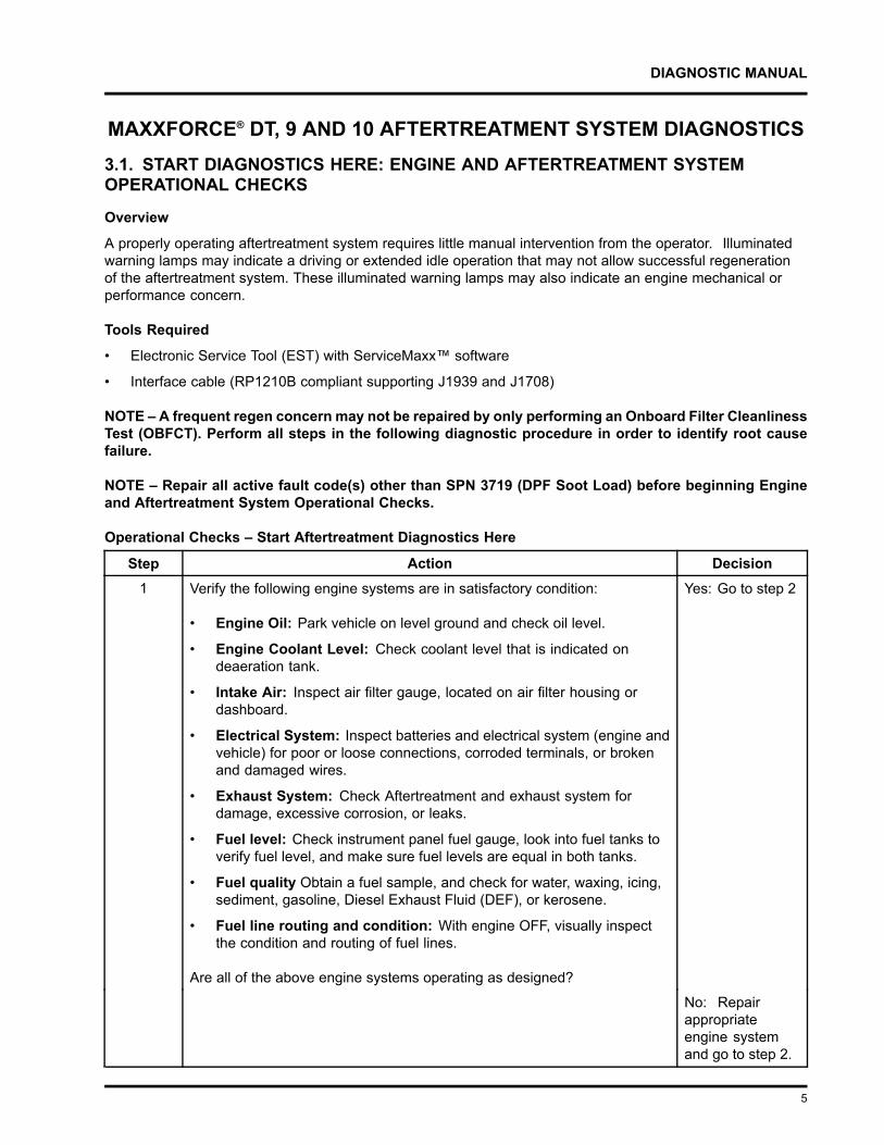
MAXXFORCE® DT, 9 AND 10 AFTERTREATMENT SYSTEM DIAGNOSTICS3.1. START DIAGNOSTICS HERE: ENGINE AND AFTERTREATMENT SYSTEMOPERATIONAL CHECKS
Overview
A properly operating aftertreatment system requires little manual intervention from the operator. Illuminatedwarning lamps may indicate a driving or extended idle operation that may not allow successful regenerationof the aftertreatment system. These illuminated warning lamps may also indicate an engine mechanical orperformance concern.
Tools Required
• Electronic Service Tool (EST) with ServiceMaxx™ software
• Interface cable (RP1210B compliant supporting J1939 and J1708)
NOTE – A frequent regen concern may not be repaired by only performing an Onboard Filter CleanlinessTest (OBFCT). Perform all steps in the following diagnostic procedure in order to identify root causefailure.
NOTE – Repair all active fault code(s) other than SPN 3719 (DPF Soot Load) before beginning Engineand Aftertreatment System Operational Checks.
Operational Checks – Start Aftertreatment Diagnostics Here
Step Action Decision1 Verify the following engine systems are in satisfactory condition:
• Engine Oil: Park vehicle on level ground and check oil level.
• Engine Coolant Level: Check coolant level that is indicated ondeaeration tank.
• Intake Air: Inspect air filter gauge, located on air filter housing ordashboard.
• Electrical System: Inspect batteries and electrical system (engine andvehicle) for poor or loose connections, corroded terminals, or brokenand damaged wires.
• Exhaust System: Check Aftertreatment and exhaust system fordamage, excessive corrosion, or leaks.
• Fuel level: Check instrument panel fuel gauge, look into fuel tanks toverify fuel level, and make sure fuel levels are equal in both tanks.
• Fuel quality Obtain a fuel sample, and check for water, waxing, icing,sediment, gasoline, Diesel Exhaust Fluid (DEF), or kerosene.
• Fuel line routing and condition: With engine OFF, visually inspectthe condition and routing of fuel lines.
Are all of the above engine systems operating as designed?
Yes: Go to step 2
No: Repairappropriateengine systemand go to step 2.
5
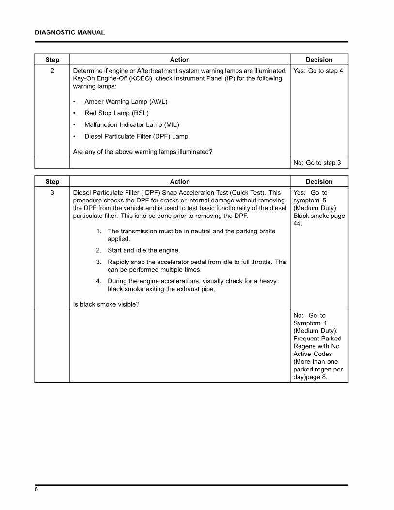
DIAGNOSTIC MANUAL
Step Action Decision2 Determine if engine or Aftertreatment system warning lamps are illuminated.
Key-On Engine-Off (KOEO), check Instrument Panel (IP) for the followingwarning lamps:
• Amber Warning Lamp (AWL)
• Red Stop Lamp (RSL)
• Malfunction Indicator Lamp (MIL)
• Diesel Particulate Filter (DPF) Lamp
Are any of the above warning lamps illuminated?
Yes: Go to step 4
No: Go to step 3
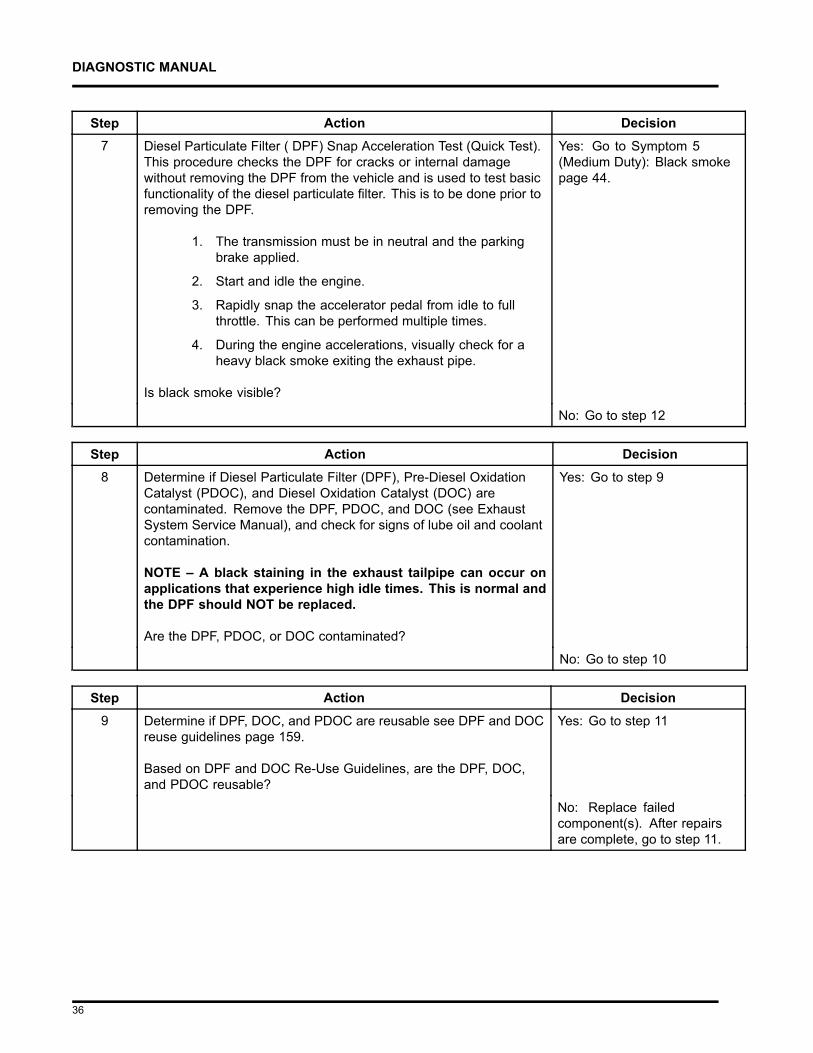
Step Action Decision3 Diesel Particulate Filter ( DPF) Snap Acceleration Test (Quick Test). This
procedure checks the DPF for cracks or internal damage without removingthe DPF from the vehicle and is used to test basic functionality of the dieselparticulate filter. This is to be done prior to removing the DPF.
1. The transmission must be in neutral and the parking brakeapplied.
2. Start and idle the engine.
3. Rapidly snap the accelerator pedal from idle to full throttle. Thiscan be performed multiple times.
4. During the engine accelerations, visually check for a heavyblack smoke exiting the exhaust pipe.
Is black smoke visible?
Yes: Go tosymptom 5(Medium Duty):Black smoke page44.
No: Go toSymptom 1(Medium Duty):Frequent ParkedRegens with NoActive Codes(More than oneparked regen perday)page 8.
6
DIAGNOSTIC MANUAL
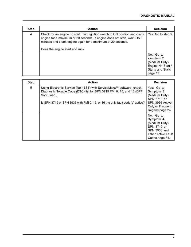
Step Action Decision4 Check for an engine no start. Turn ignition switch to ON position and crank
engine for a maximum of 20 seconds. If engine does not start, wait 2 to 3minutes and crank engine again for a maximum of 20 seconds.
Does the engine start and run?
Yes: Go to step 5
No: Go tosymptom 2(Medium Duty):Engine No Start /Starts and Stallspage 17.
Step Action Decision5 Using Electronic Service Tool (EST) with ServiceMaxx™ software, check
Diagnostic Trouble Code (DTC) list for SPN 3719 FMI 0, 15, and 16 (DPFSoot Load).
Is SPN 3719 or SPN 3936 with FMI 0, 15, or 16 the only fault code(s) active?
Yes: Go toSymptom 3(Medium Duty):SPN 3719 orSPN 3936 ActiveOnly or FrequentRegens page 24.
No: Go toSymptom 4(Medium Duty):SPN 3719 orSPN 3936 andOther Active FaultCodes page 34.
7
DIAGNOSTIC MANUAL
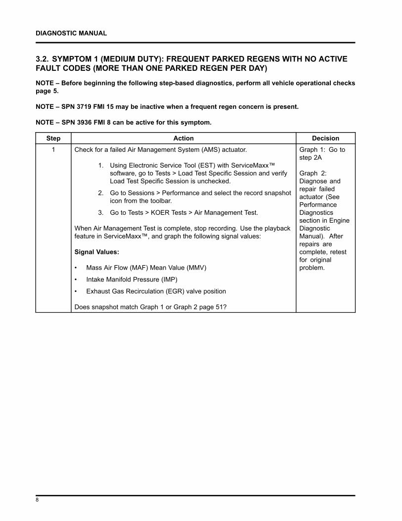
3.2. SYMPTOM 1 (MEDIUM DUTY): FREQUENT PARKED REGENS WITH NO ACTIVEFAULT CODES (MORE THAN ONE PARKED REGEN PER DAY)
NOTE – Before beginning the following step-based diagnostics, perform all vehicle operational checkspage 5.
NOTE – SPN 3719 FMI 15 may be inactive when a frequent regen concern is present.
NOTE – SPN 3936 FMI 8 can be active for this symptom.
Step Action Decision1 Check for a failed Air Management System (AMS) actuator.
1. Using Electronic Service Tool (EST) with ServiceMaxx™software, go to Tests > Load Test Specific Session and verifyLoad Test Specific Session is unchecked.
2. Go to Sessions > Performance and select the record snapshoticon from the toolbar.
3. Go to Tests > KOER Tests > Air Management Test.
When Air Management Test is complete, stop recording. Use the playbackfeature in ServiceMaxx™, and graph the following signal values:
Signal Values:
• Mass Air Flow (MAF) Mean Value (MMV)
• Intake Manifold Pressure (IMP)
• Exhaust Gas Recirculation (EGR) valve position
Does snapshot match Graph 1 or Graph 2 page 51?
Graph 1: Go tostep 2A
Graph 2:Diagnose andrepair failedactuator (SeePerformanceDiagnosticssection in EngineDiagnosticManual). Afterrepairs arecomplete, retestfor originalproblem.
8
DIAGNOSTIC MANUAL
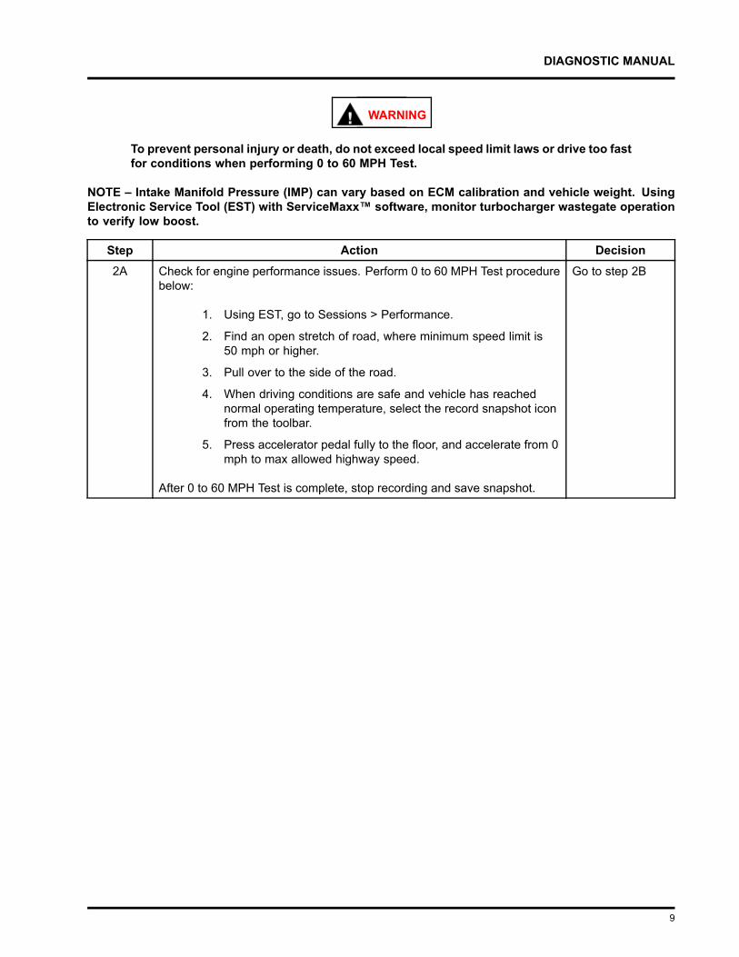
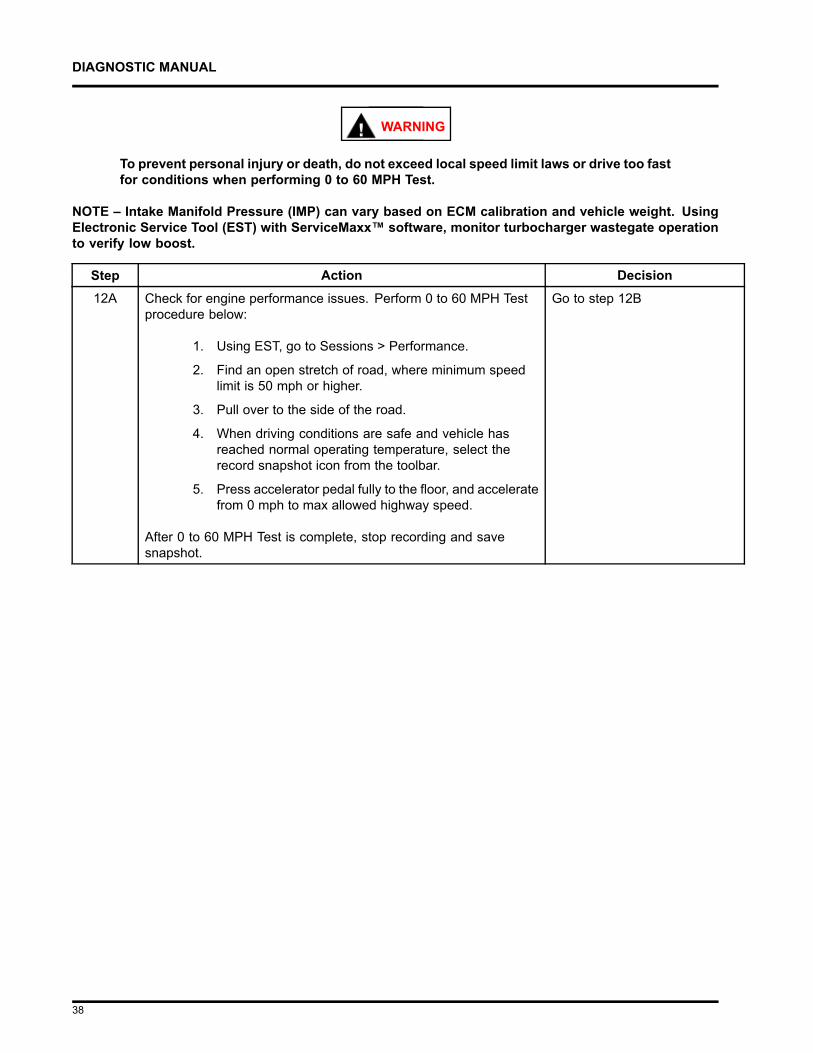
WARNING
To prevent personal injury or death, do not exceed local speed limit laws or drive too fastfor conditions when performing 0 to 60 MPH Test.
NOTE – Intake Manifold Pressure (IMP) can vary based on ECM calibration and vehicle weight. UsingElectronic Service Tool (EST) with ServiceMaxx™ software, monitor turbocharger wastegate operationto verify low boost.
Step Action Decision2A Check for engine performance issues. Perform 0 to 60 MPH Test procedure
below:
1. Using EST, go to Sessions > Performance.
2. Find an open stretch of road, where minimum speed limit is50 mph or higher.
3. Pull over to the side of the road.
4. When driving conditions are safe and vehicle has reachednormal operating temperature, select the record snapshot iconfrom the toolbar.
5. Press accelerator pedal fully to the floor, and accelerate from 0mph to max allowed highway speed.
After 0 to 60 MPH Test is complete, stop recording and save snapshot.
Go to step 2B
9
DIAGNOSTIC MANUAL
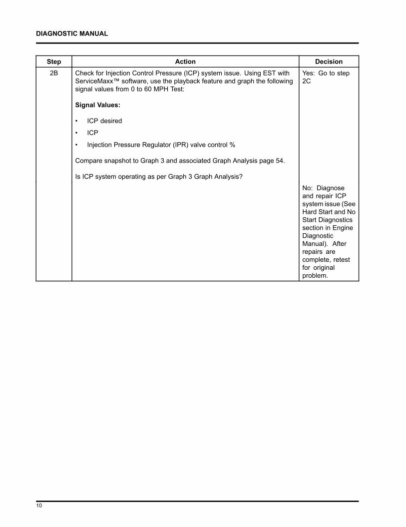
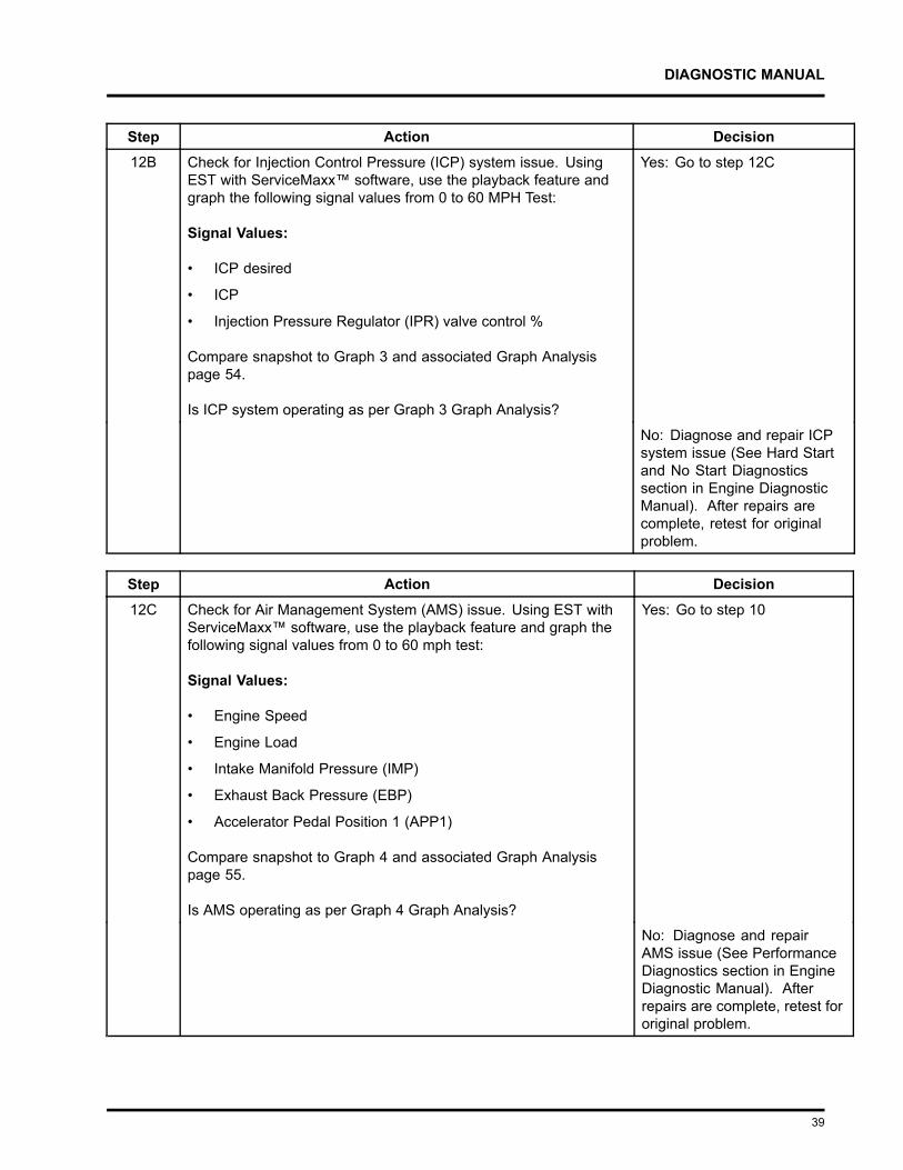
Step Action Decision2B Check for Injection Control Pressure (ICP) system issue. Using EST with
ServiceMaxx™ software, use the playback feature and graph the followingsignal values from 0 to 60 MPH Test:
Signal Values:
• ICP desired
• ICP
• Injection Pressure Regulator (IPR) valve control %
Compare snapshot to Graph 3 and associated Graph Analysis page 54.
Is ICP system operating as per Graph 3 Graph Analysis?
Yes: Go to step2C
No: Diagnoseand repair ICPsystem issue (SeeHard Start and NoStart Diagnosticssection in EngineDiagnosticManual). Afterrepairs arecomplete, retestfor originalproblem.
10
DIAGNOSTIC MANUAL
Step Action Decision2C Check for Air Management System (AMS) issue. Using EST with
ServiceMaxx™ software, use the playback feature and graph the followingsignal values from 0 to 60 MPH Test:
Signal Values:
• Engine Speed
• Engine Load
• Intake Manifold Pressure (IMP)
• Exhaust Back Pressure (EBP)
• Accelerator Pedal Position 1 (APP1)
Compare snapshot to Graph 4 and associated Graph Analysis page 55.
Is AMS operating as per Graph 4 Graph Analysis?
Yes: Go to step 3
No: Diagnose andrepair AMS issue(See PerformanceDiagnosticssection in EngineDiagnosticManual). Afterrepairs arecomplete, retestfor originalproblem.
11
DIAGNOSTIC MANUAL
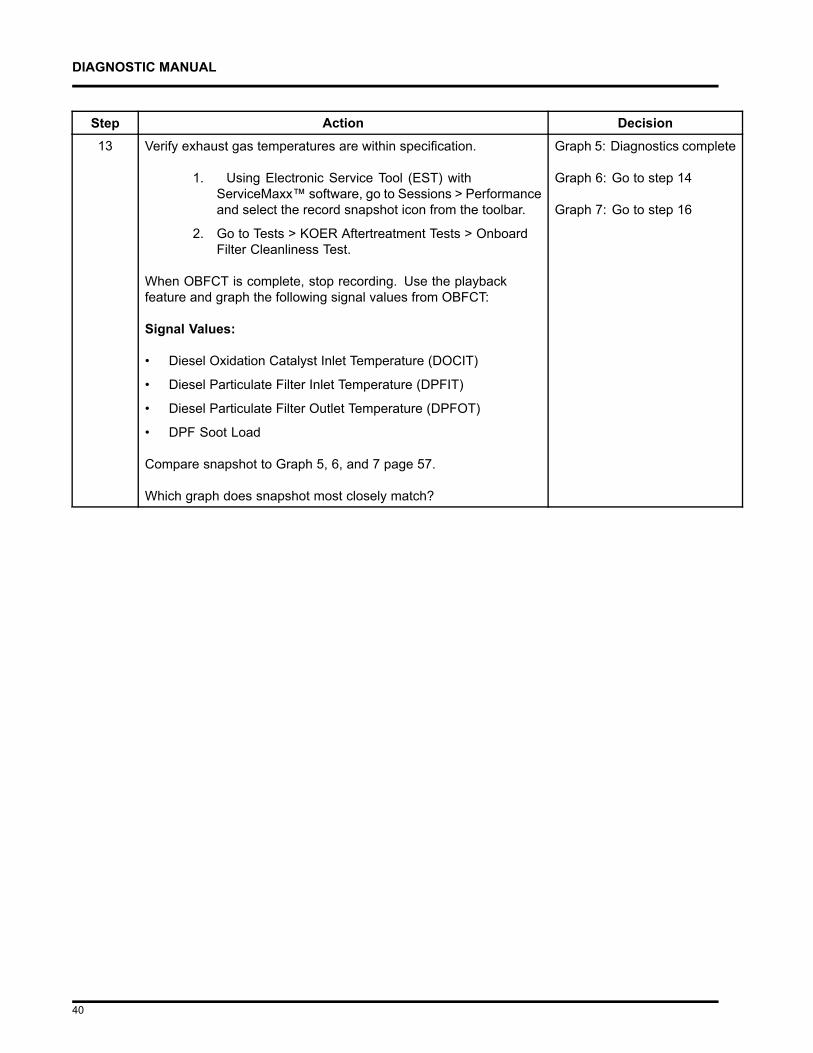
Step Action Decision3 Verify exhaust gas temperatures are within specification.
1. Using Electronic Service Tool (EST) with ServiceMaxx™software, go to Sessions > Performance and select the recordsnapshot icon from the toolbar.
2. Go to Tests > KOER Aftertreatment Tests > Onboard FilterCleanliness Test.
When OBFCT is complete, stop recording. Use the playback feature andgraph the following signal values from OBFCT:
Signal Values:
• Diesel Oxidation Catalyst Inlet Temperature (DOCIT)
• Diesel Particulate Filter Inlet Temperature (DPFIT)
• Diesel Particulate Filter Outlet Temperature (DPFOT)
• DPF Soot Load
Compare snapshot to Graph 5, 6, and 7 page 57.
Which graph does snapshot most closely match?
Graph 5:Diagnosticscomplete
Graph 6: Go tostep 4
Graph 7: Go tostep 7
Step Action Decision4 Determine if DPF or DOC is contaminated. Remove the DPF and DOC
(see Exhaust System Service Manual), and check for signs of lube oil andcoolant contamination.
NOTE – A black staining in the exhaust tailpipe can occur onapplications that experience high idle times. This is normal and theDPF should NOT be replaced.
Are the DPF or DOC contaminated?
Yes: RemovePDOC, and go tostep 5.
No: Install DPFand DOC, and goto step 7.
12
DIAGNOSTIC MANUAL
Step Action Decision5 Determine if DPF, DOC, and PDOC are reusable see the DPF and DOC
reuse guidelines page 159.
Based on DPF and DOC Re-Use Guidelines, are the DPF, DOC, andPDOC reusable?
Yes: Installremovedaftertreatmentsystemcomponents, andgo to step 6.
No: Replacefailedcomponent(s).After repairs arecomplete, go tostep 6.
Step Action Decision6 Determine root cause of exhaust system contamination. (See Engine
Symptoms Diagnostics section in Engine Diagnostic Manual.)After repairs arecomplete, go tostep 7.
13
DIAGNOSTIC MANUAL
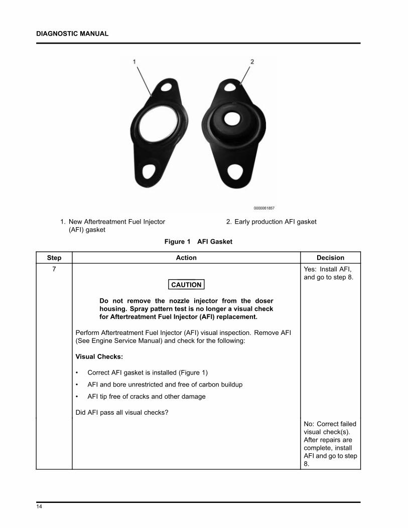
1. New Aftertreatment Fuel Injector(AFI) gasket
2. Early production AFI gasket
Figure 1 AFI Gasket
Step Action Decision7
CAUTION
Do not remove the nozzle injector from the doserhousing. Spray pattern test is no longer a visual checkfor Aftertreatment Fuel Injector (AFI) replacement.
Perform Aftertreatment Fuel Injector (AFI) visual inspection. Remove AFI(See Engine Service Manual) and check for the following:
Visual Checks:
• Correct AFI gasket is installed (Figure 1)
• AFI and bore unrestricted and free of carbon buildup
• AFI tip free of cracks and other damage
Did AFI pass all visual checks?
Yes: Install AFI,and go to step 8.
No: Correct failedvisual check(s).After repairs arecomplete, installAFI and go to step8.
14
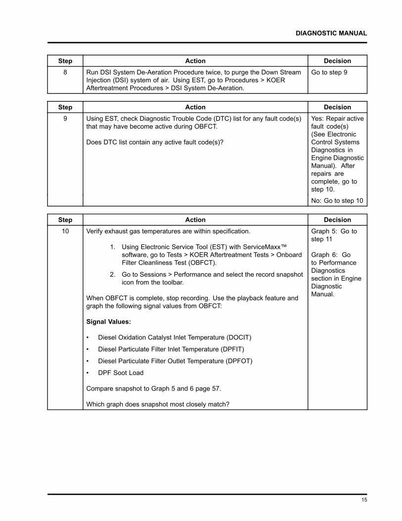
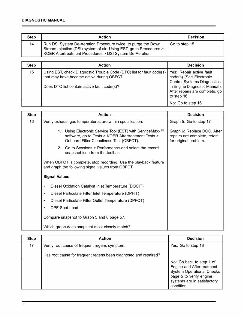
DIAGNOSTIC MANUAL
Step Action Decision8 Run DSI System De-Aeration Procedure twice, to purge the Down Stream
Injection (DSI) system of air. Using EST, go to Procedures > KOERAftertreatment Procedures > DSI System De-Aeration.
Go to step 9
Step Action Decision9 Using EST, check Diagnostic Trouble Code (DTC) list for any fault code(s)
that may have become active during OBFCT.
Does DTC list contain any active fault code(s)?
Yes: Repair activefault code(s)(See ElectronicControl SystemsDiagnostics inEngine DiagnosticManual). Afterrepairs arecomplete, go tostep 10.
No: Go to step 10
Step Action Decision10 Verify exhaust gas temperatures are within specification.
1. Using Electronic Service Tool (EST) with ServiceMaxx™software, go to Tests > KOER Aftertreatment Tests > OnboardFilter Cleanliness Test (OBFCT).
2. Go to Sessions > Performance and select the record snapshoticon from the toolbar.
When OBFCT is complete, stop recording. Use the playback feature andgraph the following signal values from OBFCT:
Signal Values:
• Diesel Oxidation Catalyst Inlet Temperature (DOCIT)
• Diesel Particulate Filter Inlet Temperature (DPFIT)
• Diesel Particulate Filter Outlet Temperature (DPFOT)
• DPF Soot Load
Compare snapshot to Graph 5 and 6 page 57.
Which graph does snapshot most closely match?
Graph 5: Go tostep 11
Graph 6: Goto PerformanceDiagnosticssection in EngineDiagnosticManual.
15
DIAGNOSTIC MANUAL
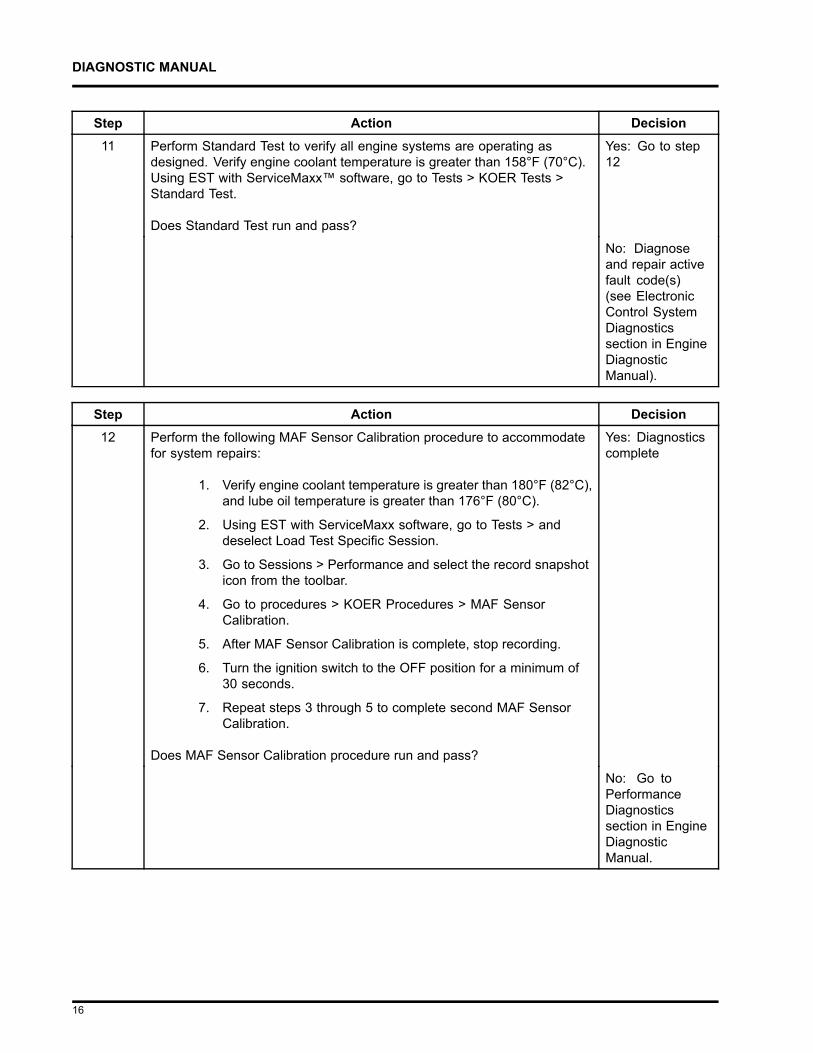
Step Action Decision11 Perform Standard Test to verify all engine systems are operating as
designed. Verify engine coolant temperature is greater than 158°F (70°C).Using EST with ServiceMaxx™ software, go to Tests > KOER Tests >Standard Test.
Does Standard Test run and pass?
Yes: Go to step12
No: Diagnoseand repair activefault code(s)(see ElectronicControl SystemDiagnosticssection in EngineDiagnosticManual).
Step Action Decision12 Perform the following MAF Sensor Calibration procedure to accommodate
for system repairs:
1. Verify engine coolant temperature is greater than 180°F (82°C),and lube oil temperature is greater than 176°F (80°C).
2. Using EST with ServiceMaxx software, go to Tests > anddeselect Load Test Specific Session.
3. Go to Sessions > Performance and select the record snapshoticon from the toolbar.
4. Go to procedures > KOER Procedures > MAF SensorCalibration.
5. After MAF Sensor Calibration is complete, stop recording.
6. Turn the ignition switch to the OFF position for a minimum of30 seconds.
7. Repeat steps 3 through 5 to complete second MAF SensorCalibration.
Does MAF Sensor Calibration procedure run and pass?
Yes: Diagnosticscomplete
No: Go toPerformanceDiagnosticssection in EngineDiagnosticManual.
16
DIAGNOSTIC MANUAL
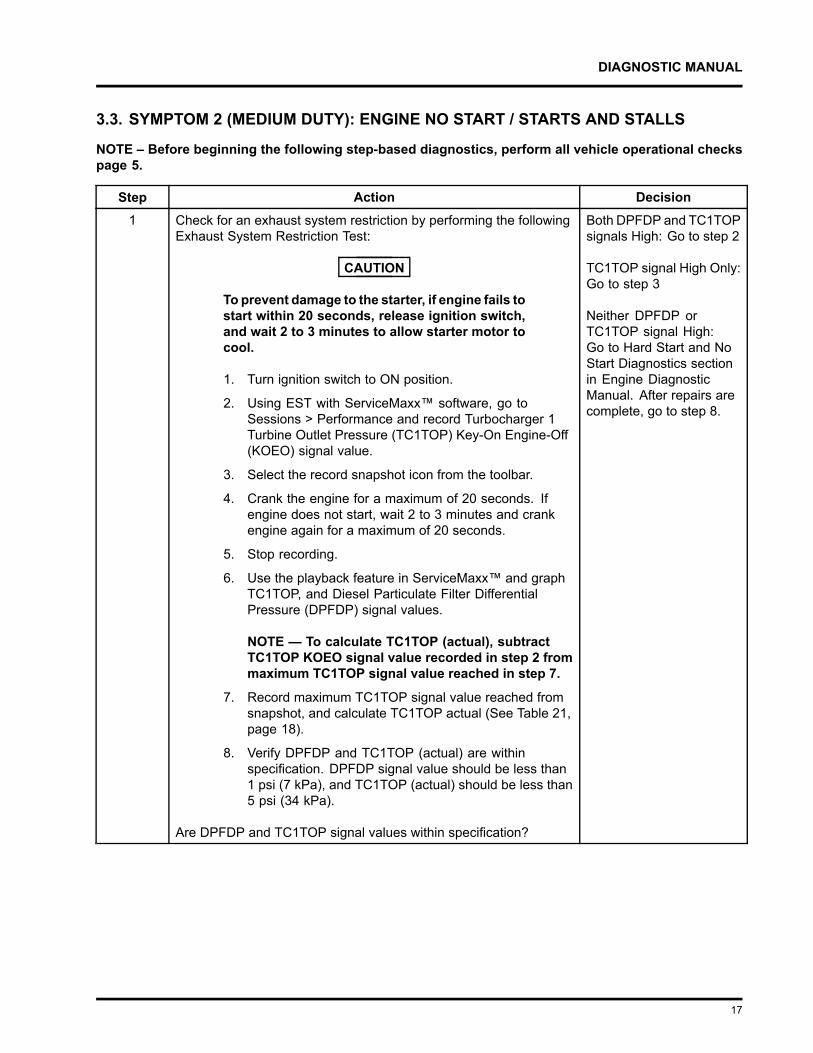
3.3. SYMPTOM 2 (MEDIUM DUTY): ENGINE NO START / STARTS AND STALLS
NOTE – Before beginning the following step-based diagnostics, perform all vehicle operational checkspage 5.
Step Action Decision1 Check for an exhaust system restriction by performing the following
Exhaust System Restriction Test:
CAUTION
To prevent damage to the starter, if engine fails tostart within 20 seconds, release ignition switch,and wait 2 to 3 minutes to allow starter motor tocool.
1. Turn ignition switch to ON position.
2. Using EST with ServiceMaxx™ software, go toSessions > Performance and record Turbocharger 1Turbine Outlet Pressure (TC1TOP) Key-On Engine-Off(KOEO) signal value.
3. Select the record snapshot icon from the toolbar.
4. Crank the engine for a maximum of 20 seconds. Ifengine does not start, wait 2 to 3 minutes and crankengine again for a maximum of 20 seconds.
5. Stop recording.
6. Use the playback feature in ServiceMaxx™ and graphTC1TOP, and Diesel Particulate Filter DifferentialPressure (DPFDP) signal values.
NOTE — To calculate TC1TOP (actual), subtractTC1TOP KOEO signal value recorded in step 2 frommaximum TC1TOP signal value reached in step 7.
7. Record maximum TC1TOP signal value reached fromsnapshot, and calculate TC1TOP actual (See Table 21,page 18).
8. Verify DPFDP and TC1TOP (actual) are withinspecification. DPFDP signal value should be less than1 psi (7 kPa), and TC1TOP (actual) should be less than5 psi (34 kPa).
Are DPFDP and TC1TOP signal values within specification?
Both DPFDP and TC1TOPsignals High: Go to step 2
TC1TOP signal High Only:Go to step 3
Neither DPFDP orTC1TOP signal High:Go to Hard Start and NoStart Diagnostics sectionin Engine DiagnosticManual. After repairs arecomplete, go to step 8.
17
DIAGNOSTIC MANUAL
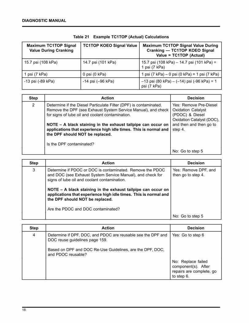
Table 21 Example TC1TOP (Actual) Calculations
Maximum TC1TOP SignalValue During Cranking
TC1TOP KOEO Signal Value Maximum TC1TOP Signal Value DuringCranking — TC1TOP KOEO Signal
Value = TC1TOP (Actual)15.7 psi (108 kPa) 14.7 psi (101 kPa) 15.7 psi (108 kPa) – 14.7 psi (101 kPa) =
1 psi (7 kPa)
1 psi (7 kPa) 0 psi (0 kPa) 1 psi (7 kPa) – 0 psi (0 kPa) = 1 psi (7 kPa)
-13 psi (-89 kPa) -14 psi (–96 kPa) –13 psi (80 kPa) – (–14) psi (-96 kPa) = 1psi (7 kPa)
Step Action Decision2 Determine if the Diesel Particulate Filter (DPF) is contaminated.
Remove the DPF (see Exhaust System Service Manual), and checkfor signs of lube oil and coolant contamination.
NOTE – A black staining in the exhaust tailpipe can occur onapplications that experience high idle times. This is normal andthe DPF should NOT be replaced.
Is the DPF contaminated?
Yes: Remove Pre-DieselOxidation Catalyst(PDOC) & DieselOxidation Catalyst (DOC),and then and then go tostep 4.
No: Go to step 5
Step Action Decision3 Determine if PDOC or DOC is contaminated. Remove the PDOC
and DOC (see Exhaust System Service Manual), and check forsigns of lube oil and coolant contamination.
NOTE – A black staining in the exhaust tailpipe can occur onapplications that experience high idle times. This is normal andthe DPF should NOT be replaced.
Are the PDOC and DOC contaminated?
Yes: Remove DPF, andthen go to step 4.
No: Go to step 5
Step Action Decision4 Determine if DPF, DOC, and PDOC are reusable see the DPF and
DOC reuse guidelines page 159.
Based on DPF and DOC Re-Use Guidelines, are the DPF, DOC,and PDOC reusable?
Yes: Go to step 6
No: Replace failedcomponent(s). Afterrepairs are complete, goto step 6.
18
DIAGNOSTIC MANUAL
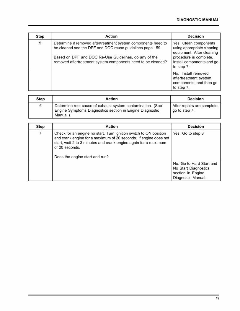
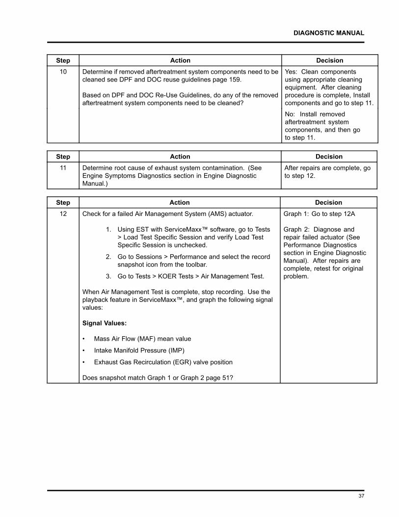
Step Action Decision5 Determine if removed aftertreatment system components need to
be cleaned see the DPF and DOC reuse guidelines page 159.
Based on DPF and DOC Re-Use Guidelines, do any of theremoved aftertreatment system components need to be cleaned?
Yes: Clean componentsusing appropriate cleaningequipment. After cleaningprocedure is complete,Install components and goto step 7.
No: Install removedaftertreatment systemcomponents, and then goto step 7.
Step Action Decision6 Determine root cause of exhaust system contamination. (See
Engine Symptoms Diagnostics section in Engine DiagnosticManual.)
After repairs are complete,go to step 7.
Step Action Decision7 Check for an engine no start. Turn ignition switch to ON position
and crank engine for a maximum of 20 seconds. If engine does notstart, wait 2 to 3 minutes and crank engine again for a maximumof 20 seconds.
Does the engine start and run?
Yes: Go to step 8
No: Go to Hard Start andNo Start Diagnosticssection in EngineDiagnostic Manual.
19
DIAGNOSTIC MANUAL
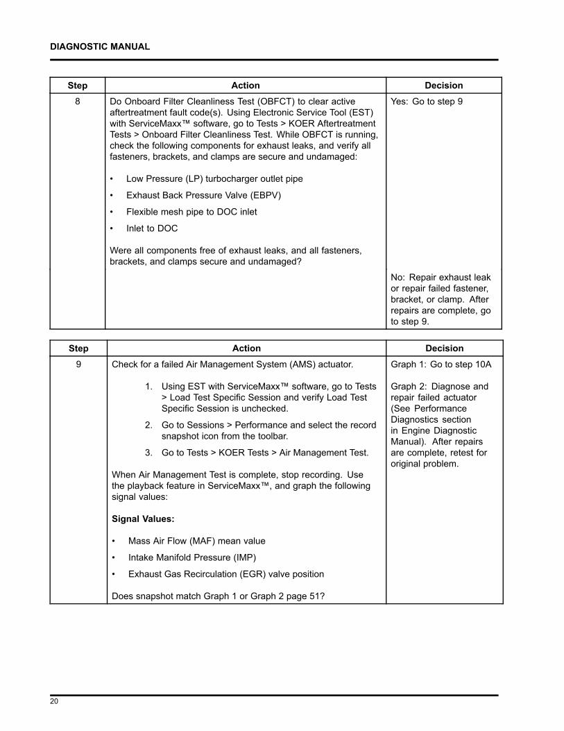
Step Action Decision8 Do Onboard Filter Cleanliness Test (OBFCT) to clear active
aftertreatment fault code(s). Using Electronic Service Tool (EST)with ServiceMaxx™ software, go to Tests > KOER AftertreatmentTests > Onboard Filter Cleanliness Test. While OBFCT is running,check the following components for exhaust leaks, and verify allfasteners, brackets, and clamps are secure and undamaged:
• Low Pressure (LP) turbocharger outlet pipe
• Exhaust Back Pressure Valve (EBPV)
• Flexible mesh pipe to DOC inlet
• Inlet to DOC
Were all components free of exhaust leaks, and all fasteners,brackets, and clamps secure and undamaged?
Yes: Go to step 9
No: Repair exhaust leakor repair failed fastener,bracket, or clamp. Afterrepairs are complete, goto step 9.
Step Action Decision9 Check for a failed Air Management System (AMS) actuator.
1. Using EST with ServiceMaxx™ software, go to Tests> Load Test Specific Session and verify Load TestSpecific Session is unchecked.
2. Go to Sessions > Performance and select the recordsnapshot icon from the toolbar.
3. Go to Tests > KOER Tests > Air Management Test.
When Air Management Test is complete, stop recording. Usethe playback feature in ServiceMaxx™, and graph the followingsignal values:
Signal Values:
• Mass Air Flow (MAF) mean value
• Intake Manifold Pressure (IMP)
• Exhaust Gas Recirculation (EGR) valve position
Does snapshot match Graph 1 or Graph 2 page 51?
Graph 1: Go to step 10A
Graph 2: Diagnose andrepair failed actuator(See PerformanceDiagnostics sectionin Engine DiagnosticManual). After repairsare complete, retest fororiginal problem.
20

DIAGNOSTIC MANUAL
WARNING
To prevent personal injury or death, do not exceed local speed limit laws or drive too fastfor conditions when performing 0 to 60 MPH Test.
NOTE – Intake Manifold Pressure (IMP) can vary based on ECM calibration and vehicle weight. UsingElectronic Service Tool (EST) with ServiceMaxx™ software, monitor turbocharger wastegate operationto verify low boost.
Step Action Decision10A Check for engine performance issues. Perform 0 to 60 MPH Test
procedure below:
1. Using EST, go to Sessions > Performance.
2. Find an open stretch of road, where minimum speedlimit is 50 mph or higher.
3. Pull over to the side of the road.
4. When driving conditions are safe and vehicle hasreached normal operating temperature, select therecord snapshot icon from the toolbar.
5. Press accelerator pedal fully to the floor, andaccelerate from 0 mph to max allowed highwayspeed.
After 0 to 60 MPH Test is complete, stop recording and savesnapshot.
Go to step 10B
21
DIAGNOSTIC MANUAL
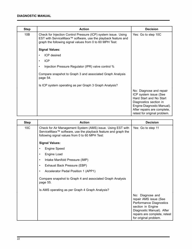
Step Action Decision10B Check for Injection Control Pressure (ICP) system issue. Using
EST with ServiceMaxx™ software, use the playback feature andgraph the following signal values from 0 to 60 MPH Test:
Signal Values:
• ICP desired
• ICP
• Injection Pressure Regulator (IPR) valve control %
Compare snapshot to Graph 3 and associated Graph Analysispage 54.
Is ICP system operating as per Graph 3 Graph Analysis?
Yes: Go to step 10C
No: Diagnose and repairICP system issue (SeeHard Start and No StartDiagnostics section inEngine Diagnostic Manual).After repairs are complete,retest for original problem.
Step Action Decision10C Check for Air Management System (AMS) issue. Using EST with
ServiceMaxx™ software, use the playback feature and graph thefollowing signal values from 0 to 60 MPH Test:
Signal Values:
• Engine Speed
• Engine Load
• Intake Manifold Pressure (IMP)
• Exhaust Back Pressure (EBP)
• Accelerator Pedal Position 1 (APP1)
Compare snapshot to Graph 4 and associated Graph Analysispage 55.
Is AMS operating as per Graph 4 Graph Analysis?
Yes: Go to step 11
No: Diagnose andrepair AMS issue (SeePerformance Diagnosticssection in EngineDiagnostic Manual). Afterrepairs are complete, retestfor original problem.
22
DIAGNOSTIC MANUAL
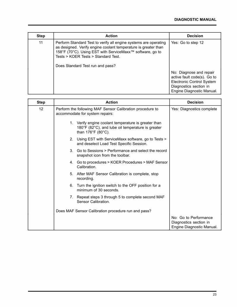
Step Action Decision11 Perform Standard Test to verify all engine systems are operating
as designed. Verify engine coolant temperature is greater than158°F (70°C). Using EST with ServiceMaxx™ software, go toTests > KOER Tests > Standard Test.
Does Standard Test run and pass?
Yes: Go to step 12
No: Diagnose and repairactive fault code(s). Go toElectronic Control SystemDiagnostics section inEngine Diagnostic Manual.
Step Action Decision12 Perform the following MAF Sensor Calibration procedure to
accommodate for system repairs:
1. Verify engine coolant temperature is greater than180°F (82°C), and lube oil temperature is greaterthan 176°F (80°C).
2. Using EST with ServiceMaxx software, go to Tests >and deselect Load Test Specific Session.
3. Go to Sessions > Performance and select the recordsnapshot icon from the toolbar.
4. Go to procedures > KOER Procedures > MAF SensorCalibration.
5. After MAF Sensor Calibration is complete, stoprecording.
6. Turn the ignition switch to the OFF position for aminimum of 30 seconds.
7. Repeat steps 3 through 5 to complete second MAFSensor Calibration.
Does MAF Sensor Calibration procedure run and pass?
Yes: Diagnostics complete
No: Go to PerformanceDiagnostics section inEngine Diagnostic Manual.
23
DIAGNOSTIC MANUAL
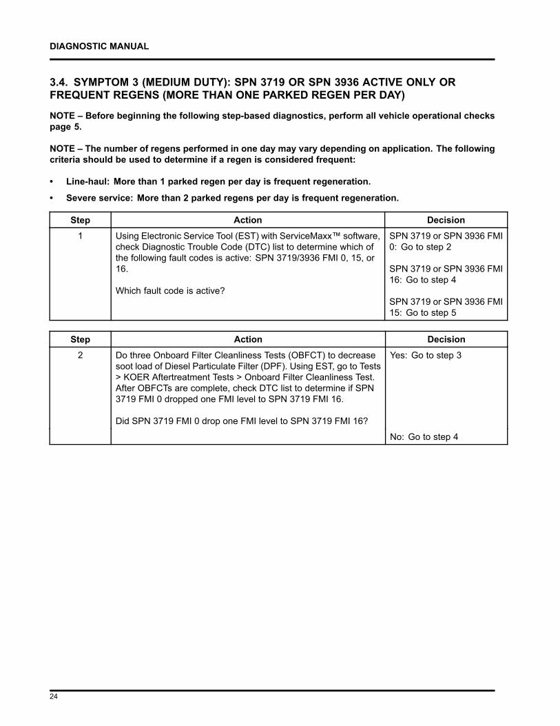
3.4. SYMPTOM 3 (MEDIUM DUTY): SPN 3719 OR SPN 3936 ACTIVE ONLY ORFREQUENT REGENS (MORE THAN ONE PARKED REGEN PER DAY)
NOTE – Before beginning the following step-based diagnostics, perform all vehicle operational checkspage 5.
NOTE – The number of regens performed in one day may vary depending on application. The followingcriteria should be used to determine if a regen is considered frequent:
• Line-haul: More than 1 parked regen per day is frequent regeneration.
• Severe service: More than 2 parked regens per day is frequent regeneration.
Step Action Decision1 Using Electronic Service Tool (EST) with ServiceMaxx™ software,
check Diagnostic Trouble Code (DTC) list to determine which ofthe following fault codes is active: SPN 3719/3936 FMI 0, 15, or16.
Which fault code is active?
SPN 3719 or SPN 3936 FMI0: Go to step 2
SPN 3719 or SPN 3936 FMI16: Go to step 4
SPN 3719 or SPN 3936 FMI15: Go to step 5
Step Action Decision2 Do three Onboard Filter Cleanliness Tests (OBFCT) to decrease
soot load of Diesel Particulate Filter (DPF). Using EST, go to Tests> KOER Aftertreatment Tests > Onboard Filter Cleanliness Test.After OBFCTs are complete, check DTC list to determine if SPN3719 FMI 0 dropped one FMI level to SPN 3719 FMI 16.
Did SPN 3719 FMI 0 drop one FMI level to SPN 3719 FMI 16?
Yes: Go to step 3
No: Go to step 4
24
DIAGNOSTIC MANUAL
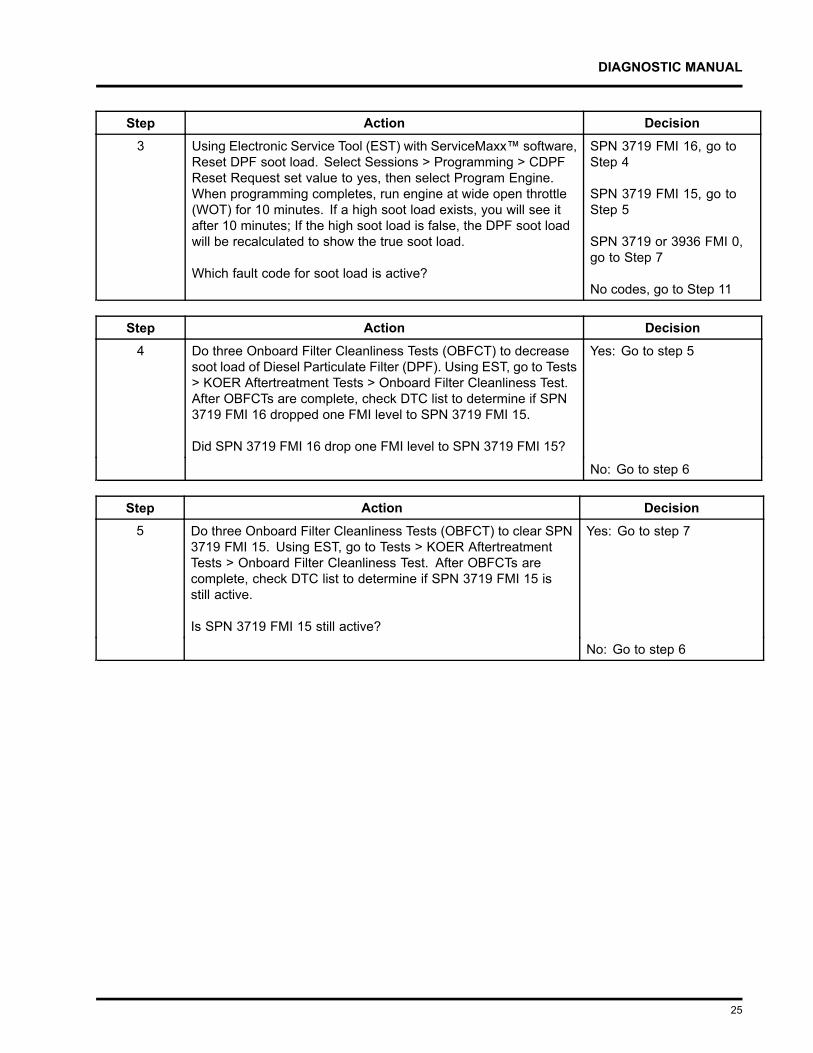
Step Action Decision3 Using Electronic Service Tool (EST) with ServiceMaxx™ software,
Reset DPF soot load. Select Sessions > Programming > CDPFReset Request set value to yes, then select Program Engine.When programming completes, run engine at wide open throttle(WOT) for 10 minutes. If a high soot load exists, you will see itafter 10 minutes; If the high soot load is false, the DPF soot loadwill be recalculated to show the true soot load.
Which fault code for soot load is active?
SPN 3719 FMI 16, go toStep 4
SPN 3719 FMI 15, go toStep 5
SPN 3719 or 3936 FMI 0,go to Step 7
No codes, go to Step 11
Step Action Decision4 Do three Onboard Filter Cleanliness Tests (OBFCT) to decrease
soot load of Diesel Particulate Filter (DPF). Using EST, go to Tests> KOER Aftertreatment Tests > Onboard Filter Cleanliness Test.After OBFCTs are complete, check DTC list to determine if SPN3719 FMI 16 dropped one FMI level to SPN 3719 FMI 15.
Did SPN 3719 FMI 16 drop one FMI level to SPN 3719 FMI 15?
Yes: Go to step 5
No: Go to step 6
Step Action Decision5 Do three Onboard Filter Cleanliness Tests (OBFCT) to clear SPN
3719 FMI 15. Using EST, go to Tests > KOER AftertreatmentTests > Onboard Filter Cleanliness Test. After OBFCTs arecomplete, check DTC list to determine if SPN 3719 FMI 15 isstill active.
Is SPN 3719 FMI 15 still active?
Yes: Go to step 7
No: Go to step 6
25
DIAGNOSTIC MANUAL
Step Action Decision6 Diesel Particulate Filter ( DPF) Snap Acceleration Test (Quick
Test). This procedure checks the DPF for cracks or internaldamage without removing the DPF from the vehicle and is usedto test basic functionality of the diesel particulate filter. This is tobe done prior to removing the DPF.
1. The transmission must be in neutral and the parkingbrake applied.
2. Start and idle the engine.
3. Rapidly snap the accelerator pedal from idle to fullthrottle. This can be performed multiple times.
4. During the engine accelerations, visually check for aheavy black smoke exiting the exhaust pipe.
Is black smoke visible?
Yes: Go to Symptom 5(Medium Duty): Black smokepage 44.
No: Go to step 11
Step Action Decision7 Determine if Diesel Particulate Filter (DPF), Pre-Diesel Oxidation
Catalyst (PDOC), and Diesel Oxidation Catalyst (DOC) arecontaminated. Remove the DPF, PDOC, and DOC (see ExhaustSystem Service Manual), and check for signs of lube oil andcoolant contamination.
NOTE – A black staining in the exhaust tailpipe can occur onapplications that experience high idle times. This is normaland the DPF should NOT be replaced.
Are the DPF, PDOC, or DOC contaminated?
Yes: Go to step 8
No: Go to step 9
Step Action Decision8 Determine if DPF, DOC, and PDOC are reusable see DPF and
DOC reuse guidelines page 159.
Based on DPF and DOC Re-Use Guidelines, are the DPF, DOC,and PDOC reusable?
Yes: Go to step 10
No: Replace failedcomponent(s). After repairsare complete, go to step 10.
26
DIAGNOSTIC MANUAL
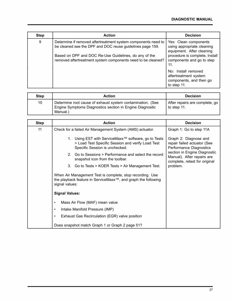
Step Action Decision9 Determine if removed aftertreatment system components need to
be cleaned see the DPF and DOC reuse guidelines page 159.
Based on DPF and DOC Re-Use Guidelines, do any of theremoved aftertreatment system components need to be cleaned?
Yes: Clean componentsusing appropriate cleaningequipment. After cleaningprocedure is complete, Installcomponents and go to step11.
No: Install removedaftertreatment systemcomponents, and then goto step 11.
Step Action Decision10 Determine root cause of exhaust system contamination. (See
Engine Symptoms Diagnostics section in Engine DiagnosticManual.)
After repairs are complete, goto step 11.
Step Action Decision11 Check for a failed Air Management System (AMS) actuator.
1. Using EST with ServiceMaxx™ software, go to Tests> Load Test Specific Session and verify Load TestSpecific Session is unchecked.
2. Go to Sessions > Performance and select the recordsnapshot icon from the toolbar.
3. Go to Tests > KOER Tests > Air Management Test.
When Air Management Test is complete, stop recording. Usethe playback feature in ServiceMaxx™, and graph the followingsignal values:
Signal Values:
• Mass Air Flow (MAF) mean value
• Intake Manifold Pressure (IMP)
• Exhaust Gas Recirculation (EGR) valve position
Does snapshot match Graph 1 or Graph 2 page 51?
Graph 1: Go to step 11A
Graph 2: Diagnose andrepair failed actuator (SeePerformance Diagnosticssection in Engine DiagnosticManual). After repairs arecomplete, retest for originalproblem.
27
DIAGNOSTIC MANUAL
WARNING
To prevent personal injury or death, do not exceed local speed limit laws or drive too fastfor conditions when performing 0 to 60 MPH Test.
NOTE – Intake Manifold Pressure (IMP) can vary based on ECM calibration and vehicle weight. UsingElectronic Service Tool (EST) with ServiceMaxx™ software, monitor turbocharger wastegate operationto verify low boost.
Step Action Decision11A Check for engine performance issues. Perform 0 to 60 MPH Test
procedure below:
1. Using EST, go to Sessions > Performance.
2. Find an open stretch of road which will safely allowfull acceleration.
3. Pull over to the side of the road.
4. When driving conditions are safe and vehicle hasreached normal operating temperature, select therecord snapshot icon from the toolbar.
5. Press accelerator pedal fully to the floor, andaccelerate from 0 mph to max allowed highwayspeed.
After 0 to 60 MPH Test is complete, stop recording and savesnapshot.
Go to step 11B
28
DIAGNOSTIC MANUAL
Step Action Decision11B Check for Injection Control Pressure (ICP) system issue. Using
EST with ServiceMaxx™ software, use the playback feature andgraph the following signal values from 0 to 60 mph test:
Signal Values:
• ICP desired
• ICP
• Injection Pressure Regulator (IPR) valve control %
Compare snapshot to Graph 3 and associated Graph Analysispage 54.
Is ICP system operating as per Graph 3 Graph Analysis?
Yes: Go to step 11C
No: Diagnose and repair ICPsystem issue (See Hard Startand No Start Diagnosticssection in Engine DiagnosticManual). After repairs arecomplete, retest for originalproblem.
Step Action Decision11C Check for Air Management System (AMS) issue. Using EST with
ServiceMaxx™ software, use the playback feature and graph thefollowing signal values from 0 to 60 mph test:
Signal Values:
• Engine Speed
• Engine Load
• Intake Manifold Pressure (IMP)
• Exhaust Back Pressure (EBP)
• Accelerator Pedal Position 1 (APP1)
Compare snapshot to Graph 4 and associated Graph Analysispage 55.
Is AMS operating as per Graph 4 Graph Analysis?
Yes: Go to step 12
No: Diagnose and repairAMS issue (See PerformanceDiagnostics section in EngineDiagnostic Manual). Afterrepairs are complete, retestfor original problem.
29
DIAGNOSTIC MANUAL
Step Action Decision12 Verify exhaust gas temperatures are within specification.
1. Using Electronic Service Tool (EST) withServiceMaxx™ software, go to Tests > KOERAftertreatment Tests > Onboard Filter CleanlinessTest (OBFCT).
2. Go to Sessions > Performance and select the recordsnapshot icon from the toolbar.
When OBFCT is complete, stop recording. Use the playbackfeature and graph the following signal values from OBFCT:
Signal Values:
• Diesel Oxidation Catalyst Inlet Temperature (DOCIT)
• Diesel Particulate Filter Inlet Temperature (DPFIT)
• Diesel Particulate Filter Outlet Temperature (DPFOT)
• DPF Soot Load
Compare snapshot to Graph 5, 6, and 7 page 57.
Which graph does snapshot most closely match?
Graph 5: Diagnosticscomplete
Graph 6: Go to step 13
Graph 7: Go to step 15
30
DIAGNOSTIC MANUAL
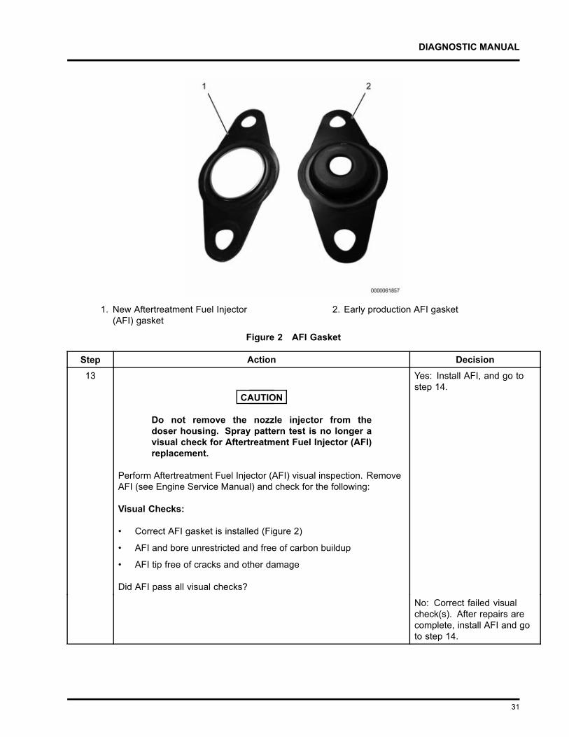
1. New Aftertreatment Fuel Injector(AFI) gasket
2. Early production AFI gasket
Figure 2 AFI Gasket
Step Action Decision13
CAUTION
Do not remove the nozzle injector from thedoser housing. Spray pattern test is no longer avisual check for Aftertreatment Fuel Injector (AFI)replacement.
Perform Aftertreatment Fuel Injector (AFI) visual inspection. RemoveAFI (see Engine Service Manual) and check for the following:
Visual Checks:
• Correct AFI gasket is installed (Figure 2)
• AFI and bore unrestricted and free of carbon buildup
• AFI tip free of cracks and other damage
Did AFI pass all visual checks?
Yes: Install AFI, and go tostep 14.
No: Correct failed visualcheck(s). After repairs arecomplete, install AFI and goto step 14.
31
DIAGNOSTIC MANUAL
Step Action Decision14 Run DSI System De-Aeration Procedure twice, to purge the Down
Stream Injection (DSI) system of air. Using EST, go to Procedures >KOER Aftertreatment Procedures > DSI System De-Aeration.
Go to step 15
Step Action Decision15 Using EST, check Diagnostic Trouble Code (DTC) list for fault code(s)
that may have become active during OBFCT.
Does DTC list contain active fault code(s)?
Yes: Repair active faultcode(s) (See ElectronicControl Systems Diagnosticsin Engine Diagnostic Manual).After repairs are complete, goto step 16.
No: Go to step 16
Step Action Decision16 Verify exhaust gas temperatures are within specification.
1. Using Electronic Service Tool (EST) with ServiceMaxx™software, go to Tests > KOER Aftertreatment Tests >Onboard Filter Cleanliness Test (OBFCT).
2. Go to Sessions > Performance and select the recordsnapshot icon from the toolbar.
When OBFCT is complete, stop recording. Use the playback featureand graph the following signal values from OBFCT:
Signal Values:
• Diesel Oxidation Catalyst Inlet Temperature (DOCIT)
• Diesel Particulate Filter Inlet Temperature (DPFIT)
• Diesel Particulate Filter Outlet Temperature (DPFOT)
• DPF Soot Load
Compare snapshot to Graph 5 and 6 page 57.
Which graph does snapshot most closely match?
Graph 5: Go to step 17
Graph 6: Replace DOC. Afterrepairs are complete, retestfor original problem.
Step Action Decision17 Verify root cause of frequent regens symptom.
Has root cause for frequent regens been diagnosed and repaired?
Yes: Go to step 18
No: Go back to step 1 ofEngine and AftertreatmentSystem Operational Checkspage 5 to verify enginesystems are in satisfactorycondition.
32
DIAGNOSTIC MANUAL
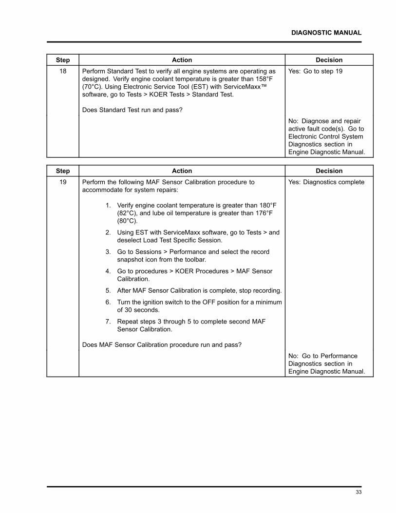
Step Action Decision18 Perform Standard Test to verify all engine systems are operating as
designed. Verify engine coolant temperature is greater than 158°F(70°C). Using Electronic Service Tool (EST) with ServiceMaxx™software, go to Tests > KOER Tests > Standard Test.
Does Standard Test run and pass?
Yes: Go to step 19
No: Diagnose and repairactive fault code(s). Go toElectronic Control SystemDiagnostics section inEngine Diagnostic Manual.
Step Action Decision19 Perform the following MAF Sensor Calibration procedure to
accommodate for system repairs:
1. Verify engine coolant temperature is greater than 180°F(82°C), and lube oil temperature is greater than 176°F(80°C).
2. Using EST with ServiceMaxx software, go to Tests > anddeselect Load Test Specific Session.
3. Go to Sessions > Performance and select the recordsnapshot icon from the toolbar.
4. Go to procedures > KOER Procedures > MAF SensorCalibration.
5. After MAF Sensor Calibration is complete, stop recording.
6. Turn the ignition switch to the OFF position for a minimumof 30 seconds.
7. Repeat steps 3 through 5 to complete second MAFSensor Calibration.
Does MAF Sensor Calibration procedure run and pass?
Yes: Diagnostics complete
No: Go to PerformanceDiagnostics section inEngine Diagnostic Manual.
33
DIAGNOSTIC MANUAL
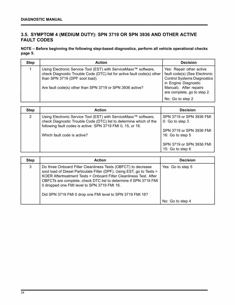
3.5. SYMPTOM 4 (MEDIUM DUTY): SPN 3719 OR SPN 3936 AND OTHER ACTIVEFAULT CODES
NOTE – Before beginning the following step-based diagnostics, perform all vehicle operational checkspage 5.
Step Action Decision1 Using Electronic Service Tool (EST) with ServiceMaxx™ software,
check Diagnostic Trouble Code (DTC) list for active fault code(s) otherthan SPN 3719 (DPF soot load).
Are fault code(s) other than SPN 3719 or SPN 3936 active?
Yes: Repair other activefault code(s) (See ElectronicControl Systems Diagnosticsin Engine DiagnosticManual). After repairsare complete, go to step 2.
No: Go to step 2
Step Action Decision2 Using Electronic Service Tool (EST) with ServiceMaxx™ software,
check Diagnostic Trouble Code (DTC) list to determine which of thefollowing fault codes is active: SPN 3719 FMI 0, 15, or 16.
Which fault code is active?
SPN 3719 or SPN 3936 FMI0: Go to step 3
SPN 3719 or SPN 3936 FMI16: Go to step 5
SPN 3719 or SPN 3936 FMI15: Go to step 6
Step Action Decision3 Do three Onboard Filter Cleanliness Tests (OBFCT) to decrease
soot load of Diesel Particulate Filter (DPF). Using EST, go to Tests >KOER Aftertreatment Tests > Onboard Filter Cleanliness Test. AfterOBFCTs are complete, check DTC list to determine if SPN 3719 FMI0 dropped one FMI level to SPN 3719 FMI 16.
Did SPN 3719 FMI 0 drop one FMI level to SPN 3719 FMI 16?
Yes: Go to step 5
No: Go to step 4
34
DIAGNOSTIC MANUAL
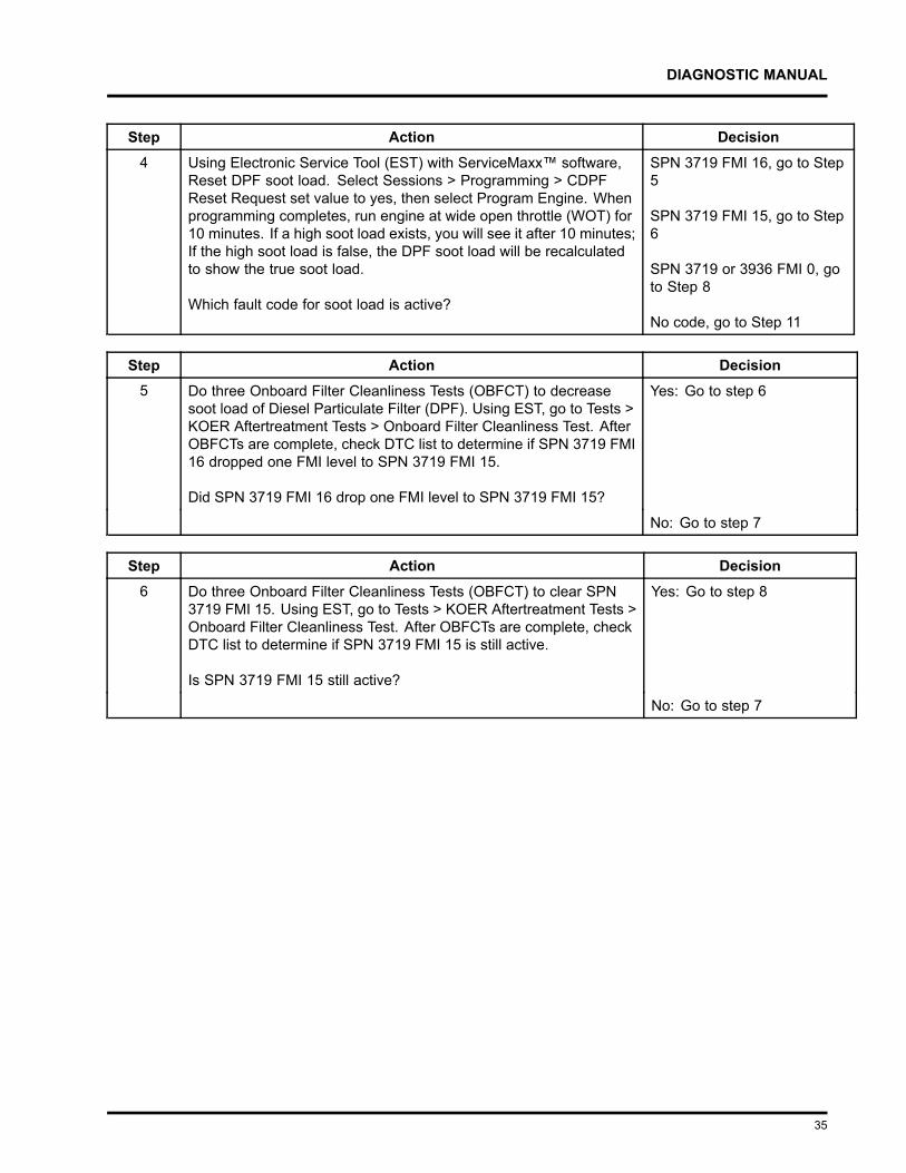
Step Action Decision4 Using Electronic Service Tool (EST) with ServiceMaxx™ software,
Reset DPF soot load. Select Sessions > Programming > CDPFReset Request set value to yes, then select Program Engine. Whenprogramming completes, run engine at wide open throttle (WOT) for10 minutes. If a high soot load exists, you will see it after 10 minutes;If the high soot load is false, the DPF soot load will be recalculatedto show the true soot load.
Which fault code for soot load is active?
SPN 3719 FMI 16, go to Step5
SPN 3719 FMI 15, go to Step6
SPN 3719 or 3936 FMI 0, goto Step 8
No code, go to Step 11
Step Action Decision5 Do three Onboard Filter Cleanliness Tests (OBFCT) to decrease
soot load of Diesel Particulate Filter (DPF). Using EST, go to Tests >KOER Aftertreatment Tests > Onboard Filter Cleanliness Test. AfterOBFCTs are complete, check DTC list to determine if SPN 3719 FMI16 dropped one FMI level to SPN 3719 FMI 15.
Did SPN 3719 FMI 16 drop one FMI level to SPN 3719 FMI 15?
Yes: Go to step 6
No: Go to step 7
Step Action Decision6 Do three Onboard Filter Cleanliness Tests (OBFCT) to clear SPN
3719 FMI 15. Using EST, go to Tests > KOER Aftertreatment Tests >Onboard Filter Cleanliness Test. After OBFCTs are complete, checkDTC list to determine if SPN 3719 FMI 15 is still active.
Is SPN 3719 FMI 15 still active?
Yes: Go to step 8
No: Go to step 7
35
DIAGNOSTIC MANUAL
Step Action Decision7 Diesel Particulate Filter ( DPF) Snap Acceleration Test (Quick Test).
This procedure checks the DPF for cracks or internal damagewithout removing the DPF from the vehicle and is used to test basicfunctionality of the diesel particulate filter. This is to be done prior toremoving the DPF.
1. The transmission must be in neutral and the parkingbrake applied.
2. Start and idle the engine.
3. Rapidly snap the accelerator pedal from idle to fullthrottle. This can be performed multiple times.
4. During the engine accelerations, visually check for aheavy black smoke exiting the exhaust pipe.
Is black smoke visible?
Yes: Go to Symptom 5(Medium Duty): Black smokepage 44.
No: Go to step 12
Step Action Decision8 Determine if Diesel Particulate Filter (DPF), Pre-Diesel Oxidation
Catalyst (PDOC), and Diesel Oxidation Catalyst (DOC) arecontaminated. Remove the DPF, PDOC, and DOC (see ExhaustSystem Service Manual), and check for signs of lube oil and coolantcontamination.
NOTE – A black staining in the exhaust tailpipe can occur onapplications that experience high idle times. This is normal andthe DPF should NOT be replaced.
Are the DPF, PDOC, or DOC contaminated?
Yes: Go to step 9
No: Go to step 10
Step Action Decision9 Determine if DPF, DOC, and PDOC are reusable see DPF and DOC
reuse guidelines page 159.
Based on DPF and DOC Re-Use Guidelines, are the DPF, DOC,and PDOC reusable?
Yes: Go to step 11
No: Replace failedcomponent(s). After repairsare complete, go to step 11.
36
DIAGNOSTIC MANUAL
Step Action Decision10 Determine if removed aftertreatment system components need to be
cleaned see DPF and DOC reuse guidelines page 159.
Based on DPF and DOC Re-Use Guidelines, do any of the removedaftertreatment system components need to be cleaned?
Yes: Clean componentsusing appropriate cleaningequipment. After cleaningprocedure is complete, Installcomponents and go to step 11.
No: Install removedaftertreatment systemcomponents, and then goto step 11.
Step Action Decision11 Determine root cause of exhaust system contamination. (See
Engine Symptoms Diagnostics section in Engine DiagnosticManual.)
After repairs are complete, goto step 12.
Step Action Decision12 Check for a failed Air Management System (AMS) actuator.
1. Using EST with ServiceMaxx™ software, go to Tests> Load Test Specific Session and verify Load TestSpecific Session is unchecked.
2. Go to Sessions > Performance and select the recordsnapshot icon from the toolbar.
3. Go to Tests > KOER Tests > Air Management Test.
When Air Management Test is complete, stop recording. Use theplayback feature in ServiceMaxx™, and graph the following signalvalues:
Signal Values:
• Mass Air Flow (MAF) mean value
• Intake Manifold Pressure (IMP)
• Exhaust Gas Recirculation (EGR) valve position
Does snapshot match Graph 1 or Graph 2 page 51?
Graph 1: Go to step 12A
Graph 2: Diagnose andrepair failed actuator (SeePerformance Diagnosticssection in Engine DiagnosticManual). After repairs arecomplete, retest for originalproblem.
37
DIAGNOSTIC MANUAL
WARNING
To prevent personal injury or death, do not exceed local speed limit laws or drive too fastfor conditions when performing 0 to 60 MPH Test.
NOTE – Intake Manifold Pressure (IMP) can vary based on ECM calibration and vehicle weight. UsingElectronic Service Tool (EST) with ServiceMaxx™ software, monitor turbocharger wastegate operationto verify low boost.
Step Action Decision12A Check for engine performance issues. Perform 0 to 60 MPH Test
procedure below:
1. Using EST, go to Sessions > Performance.
2. Find an open stretch of road, where minimum speedlimit is 50 mph or higher.
3. Pull over to the side of the road.
4. When driving conditions are safe and vehicle hasreached normal operating temperature, select therecord snapshot icon from the toolbar.
5. Press accelerator pedal fully to the floor, and acceleratefrom 0 mph to max allowed highway speed.
After 0 to 60 MPH Test is complete, stop recording and savesnapshot.
Go to step 12B
38
DIAGNOSTIC MANUAL
Step Action Decision12B Check for Injection Control Pressure (ICP) system issue. Using
EST with ServiceMaxx™ software, use the playback feature andgraph the following signal values from 0 to 60 MPH Test:
Signal Values:
• ICP desired
• ICP
• Injection Pressure Regulator (IPR) valve control %
Compare snapshot to Graph 3 and associated Graph Analysispage 54.
Is ICP system operating as per Graph 3 Graph Analysis?
Yes: Go to step 12C
No: Diagnose and repair ICPsystem issue (See Hard Startand No Start Diagnosticssection in Engine DiagnosticManual). After repairs arecomplete, retest for originalproblem.
Step Action Decision12C Check for Air Management System (AMS) issue. Using EST with
ServiceMaxx™ software, use the playback feature and graph thefollowing signal values from 0 to 60 mph test:
Signal Values:
• Engine Speed
• Engine Load
• Intake Manifold Pressure (IMP)
• Exhaust Back Pressure (EBP)
• Accelerator Pedal Position 1 (APP1)
Compare snapshot to Graph 4 and associated Graph Analysispage 55.
Is AMS operating as per Graph 4 Graph Analysis?
Yes: Go to step 10
No: Diagnose and repairAMS issue (See PerformanceDiagnostics section in EngineDiagnostic Manual). Afterrepairs are complete, retest fororiginal problem.
39
DIAGNOSTIC MANUAL
Step Action Decision13 Verify exhaust gas temperatures are within specification.
1. Using Electronic Service Tool (EST) withServiceMaxx™ software, go to Sessions > Performanceand select the record snapshot icon from the toolbar.
2. Go to Tests > KOER Aftertreatment Tests > OnboardFilter Cleanliness Test.
When OBFCT is complete, stop recording. Use the playbackfeature and graph the following signal values from OBFCT:
Signal Values:
• Diesel Oxidation Catalyst Inlet Temperature (DOCIT)
• Diesel Particulate Filter Inlet Temperature (DPFIT)
• Diesel Particulate Filter Outlet Temperature (DPFOT)
• DPF Soot Load
Compare snapshot to Graph 5, 6, and 7 page 57.
Which graph does snapshot most closely match?
Graph 5: Diagnostics complete
Graph 6: Go to step 14
Graph 7: Go to step 16
40

DIAGNOSTIC MANUAL
1. New Aftertreatment Fuel Injector(AFI) gasket
2. Early production AFI gasket
Figure 3 AFI Gasket
Step Action Decision14
CAUTION
Do not remove the nozzle injector from thedoser housing. Spray pattern test is no longera visual check for Aftertreatment Fuel Injector(AFI) replacement.
Perform Aftertreatment Fuel Injector (AFI) visual inspection.Remove AFI (see Engine Service Manual) and check for thefollowing:
Visual Checks:
• Correct AFI gasket is installed (Figure 4)
• AFI and bore unrestricted and free of carbon buildup
• AFI tip free of cracks and other damage
Did AFI pass all visual checks?
Yes: Install AFI, and go to step15
No: Correct failed visualcheck(s). After repairs arecomplete, install AFI and go tostep 15.
41
DIAGNOSTIC MANUAL
Step Action Decision15 Run DSI System De-Aeration Procedure twice, to purge the Down
Stream Injection (DSI) system of air. Using EST, go to Procedures> KOER Aftertreatment Procedures > DSI System De-Aeration. Go to step 16
Step Action Decision16 Using EST, check Diagnostic Trouble Code (DTC) list for fault
code(s) that may have become active during OBFCT.
Does DTC list contain active fault code(s)?
Yes: Repair active faultcode(s) (See Electronic ControlSystems Diagnostics in EngineDiagnostic Manual). Afterrepairs are complete, go to step17.
No: Go to step 17
Step Action Decision17 Verify exhaust gas temperatures are within specification.
1. Using Electronic Service Tool (EST) withServiceMaxx™ software, go to Tests > KOERAftertreatment Tests > Onboard Filter Cleanliness Test(OBFCT).
2. Go to Sessions > Performance and select the recordsnapshot icon from the toolbar.
When OBFCT is complete, stop recording. Use the playbackfeature and graph the following signal values from OBFCT:
Signal Values:
• Diesel Oxidation Catalyst Inlet Temperature (DOCIT)
• Diesel Particulate Filter Inlet Temperature (DPFIT)
• Diesel Particulate Filter Outlet Temperature (DPFOT)
• DPF Soot Load
Compare snapshot to Graph 5 and 6 page 57.
Which graph does snapshot most closely match?
Graph 5: Go to step 18
Graph 6: Replace DOC. Afterrepairs are complete, retest fororiginal problem.
Step Action Decision18 Verify root cause of frequent regens symptom.
Has root cause for frequent regens been diagnosed and repaired?
Yes: Go to step 19
No: Go back to step 1 of Engineand Aftertreatment SystemOperational Checks on page 5to verify engine systems are insatisfactory condition.
42
DIAGNOSTIC MANUAL
Step Action Decision19 Perform Standard Test to verify all engine systems are operating
as designed. Verify engine coolant temperature is greater than158°F (70°C). Using EST with ServiceMaxx software, go to Tests >KOER Tests > Standard Test.
Does Standard Test run and pass?
Yes: Go to step 20
No: Diagnose and repair activefault code(s) (See ElectronicControl System Diagnosticssection in Engine DiagnosticManual).
Step Action Decision20 Perform the following MAF Sensor Calibration procedure to
accommodate for system repairs:
1. Verify engine coolant temperature is greater than180°F (82°C), and lube oil temperature is greater than176°F (80°C).
2. Using EST with ServiceMaxx software, go to Tests >and deselect Load Test Specific Session.
3. Go to Sessions > Performance and select the recordsnapshot icon from the toolbar.
4. Go to procedures > KOER Procedures > MAF SensorCalibration.
5. After MAF Sensor Calibration is complete, stoprecording.
6. Turn the ignition switch to the OFF position for aminimum of 30 seconds.
7. Repeat steps 3 through 5 to complete second MAFSensor Calibration.
Does MAF Sensor Calibration procedure run and pass?
Yes: Diagnostics complete
No: Go to PerformanceDiagnostics section in EngineDiagnostic Manual.
43
DIAGNOSTIC MANUAL
3.6. SYMPTOM 5 (MEDIUM DUTY) : BLACK SMOKE
OVERVIEW: Hydrocarbon slip occurs when diesel fuel does not fully combust in the aftertreatmenttreatment system and slips through the Diesel Particulate Filter (DPF) into the clean side of theexhaust. Hydrocarbon slip is associated with high idle time. The DPF should NOT be replaced due toblack staining in the exhaust.
NOTE – The DPF is not 100 percent efficient. Some evidence of exhaust soot is normal, and does notindicate a malfunctioning DPF.
WARNING
To prevent unexpected movement of the vehicle and possible serious personal injury ordeath, park the vehicle on a flat, level surface, apply the parking brake, turn the engineoff and chock the wheels to prevent the vehicle from moving in either direction.
NOTE – Before beginning the following step-based diagnostics, perform all vehicle operational checkspage 5.
Step Action Decision1 Diesel Particulate Filter ( DPF) Snap Acceleration Test (Quick
Test). This procedure checks the DPF for cracks or internaldamage without removing the DPF from the vehicle and is usedto test basic functionality of the DPF. This is to be done prior toremoving the DPF.
1. The transmission must be in neutral and the parkingbrake applied.
2. Start and idle the engine.
3. Rapidly snap the accelerator pedal from idle to fullthrottle. This can be performed multiple times.
4. During the engine accelerations, visually check for aheavy black smoke exiting the exhaust pipe.
Is black smoke visible?
Yes: Go to step 2
No: End of diagnostics
Step Action Decision2 Remove and Inspect the Diesel Particulate Filter (DPF) (see
Exhaust System manual). At this time do NOT remove theDiesel Oxidation Catalyst (DOC).
Compare the DPF to the DPF and DOC Reuse Guidelines page159.
Can the DPF be reused?
Yes: Install the DPF and go tostep 3
No: Replace the DPF and go tostep 4
44
DIAGNOSTIC MANUAL
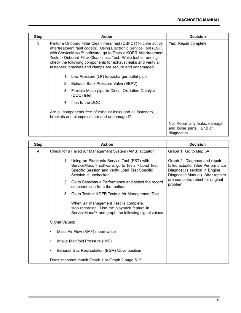
Step Action Decision3 Perform Onboard Filter Cleanliness Test (OBFCT) to clear active
aftertreatment fault code(s). Using Electronic Service Tool (EST)with ServiceMaxx™ software, go to Tests > KOER AftertreatmentTests > Onboard Filter Cleanliness Test. While test is running,check the following components for exhaust leaks and verify allfasteners, brackets and clamps are secure and undamaged.
1. Low Pressure (LP) turbocharger outlet pipe
2. Exhaust Back Pressure Valve (EBPV)
3. Flexible Mesh pipe to Diesel Oxidation Catalyst(DOC) Inlet
4. Inlet to the DOC
Are all components free of exhaust leaks and all fasteners,brackets and clamps secure and undamaged?
Yes: Repair complete
No: Repair any leaks, damage,and loose parts. End ofdiagnostics.
Step Action Decision4 Check for a Failed Air Management System (AMS) actuator.
1. Using an Electronic Service Tool (EST) withServiceMaxx™ software, go to Tests > Load TestSpecific Session and verify Load Test SpecificSession is unchecked.
2. Go to Sessions > Performance and select the recordsnapshot icon from the toolbar.
3. Go to Tests > KOER Tests > Air Management Test.
When air management Test is complete,stop recording. Use the playback feature inServiceMaxx™ and graph the following signal values.
Signal Values:
• Mass Air Flow (MAF) mean value
• Intake Manifold Pressure (IMP)
• Exhaust Gas Recirculation (EGR) Valve position
Does snapshot match Graph 1 or Graph 2 page 51?
Graph 1: Go to step 5A
Graph 2: Diagnose and repairfailed actuator (See PerformanceDiagnostics section in EngineDiagnostic Manual). After repairsare complete, retest for originalproblem.
45
DIAGNOSTIC MANUAL
WARNING
To prevent personal injury or death, do not exceed local speed limit laws or drive too fastfor conditions when performing 0 to 60 MPH Test.
NOTE – Intake Manifold Pressure (IMP) can vary based on ECM calibration and vehicle weight. UsingElectronic Service Tool (EST) with ServiceMaxx™ software, monitor turbocharger wastegate operationto verify low boost.
Step Action Decision5A Check for engine performance issues. Perform 0 to 60 MPH Test
procedure below.
1. Using Electronic Service Tool (EST) withServiceMaxx™ software, go to Sessions >Performance
2. Find an open stretch of road where minimum speedlimit is 50 MPH or higher.
3. Pull over to the side of the road.
4. When driving conditions are safe and vehicle hasreached normal operating temperature, select therecord snapshot icon from the toolbar.
5. Press accelerator pedal fully to the floor andaccelerate from 0 MPH to max allowed highwayspeed.
After 0 to 60 MPH Test is complete, stop recording and savesnapshot.
Go to step 5B
46
DIAGNOSTIC MANUAL
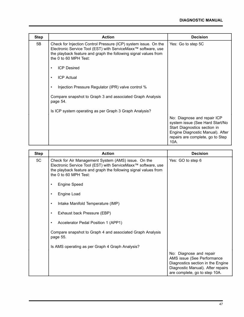
Step Action Decision5B Check for Injection Control Pressure (ICP) system issue. On the
Electronic Service Tool (EST) with ServiceMaxx™ software, usethe playback feature and graph the following signal values fromthe 0 to 60 MPH Test:
• ICP Desired
• ICP Actual
• Injection Pressure Regulator (IPR) valve control %
Compare snapshot to Graph 3 and associated Graph Analysispage 54.
Is ICP system operating as per Graph 3 Graph Analysis?
Yes: Go to step 5C
No: Diagnose and repair ICPsystem issue (See Hard Start/NoStart Diagnostics section inEngine Diagnostic Manual). Afterrepairs are complete, go to Step10A.
Step Action Decision5C Check for Air Management System (AMS) issue. On the
Electronic Service Tool (EST) with ServiceMaxx™ software, usethe playback feature and graph the following signal values fromthe 0 to 60 MPH Test:
• Engine Speed
• Engine Load
• Intake Manifold Temperature (IMP)
• Exhaust back Pressure (EBP)
• Accelerator Pedal Position 1 (APP1)
Compare snapshot to Graph 4 and associated Graph Analysispage 55.
Is AMS operating as per Graph 4 Graph Analysis?
Yes: GO to step 6
No: Diagnose and repairAMS issue (See PerformanceDiagnostics section in the EngineDiagnostic Manual). After repairsare complete, go to step 10A.
47
DIAGNOSTIC MANUAL
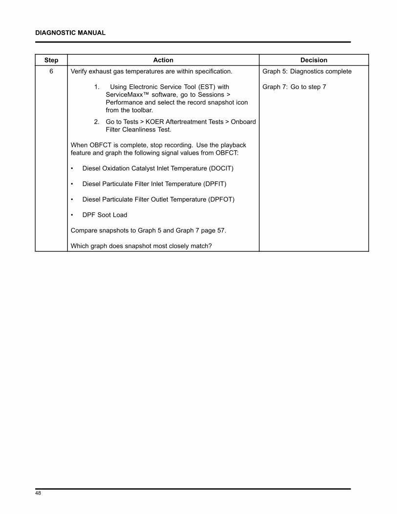
Step Action Decision6 Verify exhaust gas temperatures are within specification.
1. Using Electronic Service Tool (EST) withServiceMaxx™ software, go to Sessions >Performance and select the record snapshot iconfrom the toolbar.
2. Go to Tests > KOER Aftertreatment Tests > OnboardFilter Cleanliness Test.
When OBFCT is complete, stop recording. Use the playbackfeature and graph the following signal values from OBFCT:
• Diesel Oxidation Catalyst Inlet Temperature (DOCIT)
• Diesel Particulate Filter Inlet Temperature (DPFIT)
• Diesel Particulate Filter Outlet Temperature (DPFOT)
• DPF Soot Load
Compare snapshots to Graph 5 and Graph 7 page 57.
Which graph does snapshot most closely match?
Graph 5: Diagnostics complete
Graph 7: Go to step 7
48
DIAGNOSTIC MANUAL
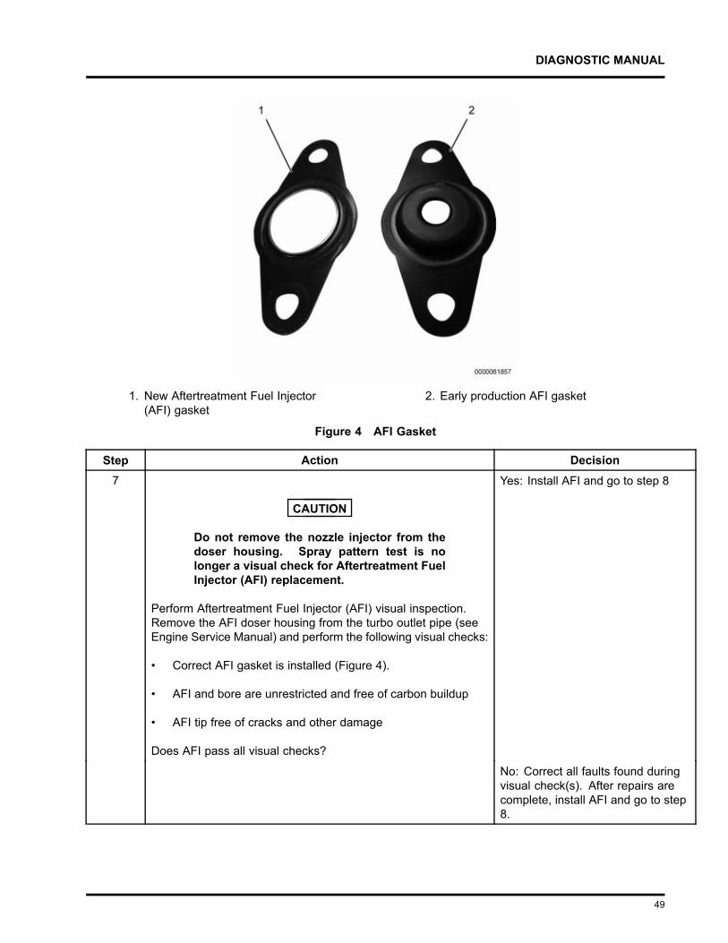
1. New Aftertreatment Fuel Injector(AFI) gasket
2. Early production AFI gasket
Figure 4 AFI Gasket
Step Action Decision7
CAUTION
Do not remove the nozzle injector from thedoser housing. Spray pattern test is nolonger a visual check for Aftertreatment FuelInjector (AFI) replacement.
Perform Aftertreatment Fuel Injector (AFI) visual inspection.Remove the AFI doser housing from the turbo outlet pipe (seeEngine Service Manual) and perform the following visual checks:
• Correct AFI gasket is installed (Figure 4).
• AFI and bore are unrestricted and free of carbon buildup
• AFI tip free of cracks and other damage
Does AFI pass all visual checks?
Yes: Install AFI and go to step 8
No: Correct all faults found duringvisual check(s). After repairs arecomplete, install AFI and go to step8.
49
DIAGNOSTIC MANUAL
Step Action Decision8 Run Down Stream Injection (DSI) System De-Aeration
Procedure two times, to purge the DSI system of air. Using theElectronic Service Tool (EST) with ServiceMaxx™ software,go to Procedures > KOER Aftertreatment Procedures > DSISystem De-Aeration.
Go to step 9
Step Action Decision9 Using Electronic Service Tool (EST) with ServiceMaxx™
software, check Diagnostic Trouble Code (DTC) list for any faultcode(s) that may have become active during OBFCT.
Does DTC list contain any active fault code(s)?
Yes: Diagnose and repair activefault code(s) (See Electronic ControlSystem Diagnostics in EngineDiagnostic Manual). After repairsare complete, go to step 10.
No: Go to step 10
Step Action Decision10 Verify exhaust gas temperatures are within specification.
1. Using Electronic Service Tool (EST) withServiceMaxx™ software, go to Tests > KOERAftertreatment Tests > Onboard Filter CleanlinessTest (OBFCT).
2. Go to Sessions > Performance and select therecord snapshot icon from the toolbar.
When OBFCT is complete, stop recording. Use the playbackfeature and graph the following signal values from OBFCT:
• Diesel Oxidation Catalyst Inlet Temperature (DOCIT)
• Diesel Particulate Filter Inlet Temperature (DPFIT)
• Diesel Particulate Filter Outlet Temperature (DPFOT)
• DPF Soot Load
Compare snapshot to Graph 5 and 6 page 57.
Which graph does snapshot most closely match?
Graph 5: End of diagnostics
Graph 6: Go to PerformanceDiagnostics section in the EngineDiagnostics Manual.
50
DIAGNOSTIC MANUAL
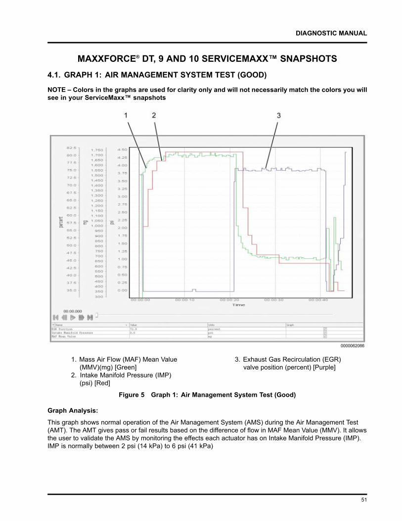
MAXXFORCE® DT, 9 AND 10 SERVICEMAXX™ SNAPSHOTS4.1. GRAPH 1: AIR MANAGEMENT SYSTEM TEST (GOOD)
NOTE – Colors in the graphs are used for clarity only and will not necessarily match the colors you willsee in your ServiceMaxx™ snapshots
1. Mass Air Flow (MAF) Mean Value(MMV)(mg) [Green]
2. Intake Manifold Pressure (IMP)(psi) [Red]
3. Exhaust Gas Recirculation (EGR)valve position (percent) [Purple]
Figure 5 Graph 1: Air Management System Test (Good)
Graph Analysis:
This graph shows normal operation of the Air Management System (AMS) during the Air Management Test(AMT). The AMT gives pass or fail results based on the difference of flow in MAF Mean Value (MMV). It allowsthe user to validate the AMS by monitoring the effects each actuator has on Intake Manifold Pressure (IMP).IMP is normally between 2 psi (14 kPa) to 6 psi (41 kPa)
51
DIAGNOSTIC MANUAL
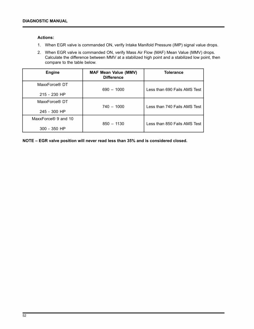
Actions:
1. When EGR valve is commanded ON, verify Intake Manifold Pressure (IMP) signal value drops.
2. When EGR valve is commanded ON, verify Mass Air Flow (MAF) Mean Value (MMV) drops.Calculate the difference between MMV at a stabilized high point and a stabilized low point, thencompare to the table below.
Engine MAF Mean Value (MMV)Difference
Tolerance
MaxxForce® DT
215 - 230 HP690 – 1000 Less than 690 Fails AMS Test
MaxxForce® DT
245 - 300 HP740 – 1000 Less than 740 Fails AMS Test
MaxxForce® 9 and 10
300 - 350 HP850 – 1130 Less than 850 Fails AMS Test
NOTE – EGR valve position will never read less than 35% and is considered closed.
52
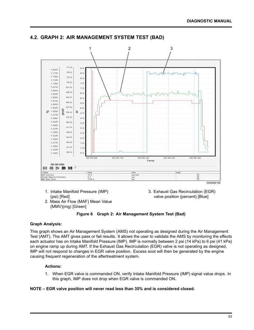
DIAGNOSTIC MANUAL
4.2. GRAPH 2: AIR MANAGEMENT SYSTEM TEST (BAD)
1. Intake Manifold Pressure (IMP)(psi) [Red]
2. Mass Air Flow (MAF) Mean Value(MMV)(mg) [Green]
3. Exhaust Gas Recirculation (EGR)valve position (percent) [Blue]
Figure 6 Graph 2: Air Management System Test (Bad)
Graph Analysis:
This graph shows an Air Management System (AMS) not operating as designed during the Air ManagementTest (AMT). The AMT gives pass or fail results. It allows the user to validate the AMS by monitoring the effectseach actuator has on Intake Manifold Pressure (IMP). IMP is normally between 2 psi (14 kPa) to 6 psi (41 kPa)on engine ramp up during AMT. If the Exhaust Gas Recirculation (EGR) valve is not operating as designed,IMP will not respond to changes in EGR valve position. Excess soot will then be generated by the enginecausing frequent regeneration of the aftertreatment system.
Actions:
1. When EGR valve is commanded ON, verify Intake Manifold Pressure (IMP) signal value drops. Inthis graph, IMP does not drop when EGR valve is commanded ON.
NOTE – EGR valve position will never read less than 35% and is considered closed.
53
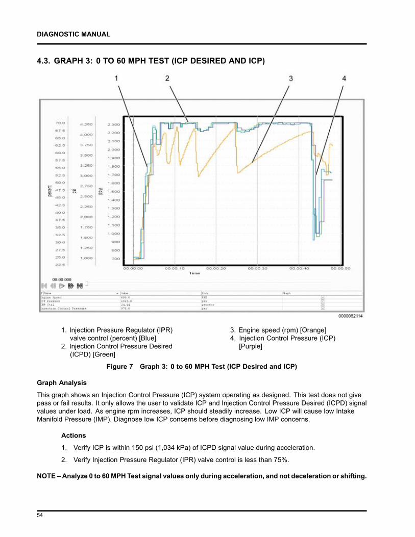
DIAGNOSTIC MANUAL
4.3. GRAPH 3: 0 TO 60 MPH TEST (ICP DESIRED AND ICP)
1. Injection Pressure Regulator (IPR)valve control (percent) [Blue]
2. Injection Control Pressure Desired(ICPD) [Green]
3. Engine speed (rpm) [Orange]4. Injection Control Pressure (ICP)
[Purple]
Figure 7 Graph 3: 0 to 60 MPH Test (ICP Desired and ICP)
Graph Analysis
This graph shows an Injection Control Pressure (ICP) system operating as designed. This test does not givepass or fail results. It only allows the user to validate ICP and Injection Control Pressure Desired (ICPD) signalvalues under load. As engine rpm increases, ICP should steadily increase. Low ICP will cause low IntakeManifold Pressure (IMP). Diagnose low ICP concerns before diagnosing low IMP concerns.
Actions
1. Verify ICP is within 150 psi (1,034 kPa) of ICPD signal value during acceleration.
2. Verify Injection Pressure Regulator (IPR) valve control is less than 75%.
NOTE – Analyze 0 to 60MPH Test signal values only during acceleration, and not deceleration or shifting.
54
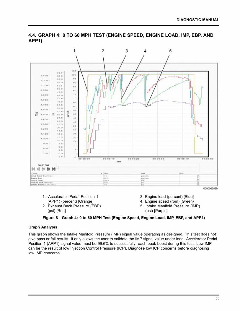
DIAGNOSTIC MANUAL
4.4. GRAPH 4: 0 TO 60 MPH TEST (ENGINE SPEED, ENGINE LOAD, IMP, EBP, ANDAPP1)
1. Accelerator Pedal Position 1(APP1) (percent) [Orange]
2. Exhaust Back Pressure (EBP)(psi) [Red]
3. Engine load (percent) [Blue]4. Engine speed (rpm) [Green5. Intake Manifold Pressure (IMP)
(psi) [Purple]
Figure 8 Graph 4: 0 to 60 MPH Test (Engine Speed, Engine Load, IMP, EBP, and APP1)
Graph Analysis
This graph shows the Intake Manifold Pressure (IMP) signal value operating as designed. This test does notgive pass or fail results. It only allows the user to validate the IMP signal value under load. Accelerator PedalPosition 1 (APP1) signal value must be 99.6% to successfully reach peak boost during this test. Low IMPcan be the result of low Injection Control Pressure (ICP). Diagnose low ICP concerns before diagnosinglow IMP concerns.
55
DIAGNOSTIC MANUAL
Actions
1. Verify IMP signal value is between 36 psi (248 kPa) to 42 psi* (289 kPa), with APP1 signal valueat 99.6%, and engine speed between 1800 rpm to 2200 rpm.
2. Verify Exhaust Back Pressure (EBP) is less than 70 psi (414 kPa), with APP1 signal value at99.6%, and engine speed between 1800 rpm to 2200 rpm.
NOTE – * IMP signal value may be as low as 29 psi (221 kPa) on lower horsepower configurations.
NOTE – Analyze 0 to 60 mph test signal values only during acceleration, and not deceleration or shifting.
56
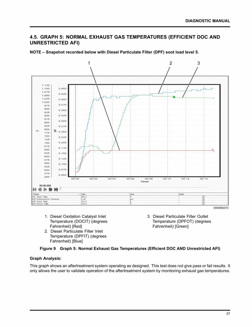
DIAGNOSTIC MANUAL
4.5. GRAPH 5: NORMAL EXHAUST GAS TEMPERATURES (EFFICIENT DOC ANDUNRESTRICTED AFI)
NOTE – Snapshot recorded below with Diesel Particulate Filter (DPF) soot load level 5.
1. Diesel Oxidation Catalyst InletTemperature (DOCIT) (degreesFahrenheit) [Red]
2. Diesel Particulate Filter InletTemperature (DPFIT) (degreesFahrenheit) [Blue]
3. Diesel Particulate Filter OutletTemperature (DPFOT) (degreesFahrenheit) [Green]
Figure 9 Graph 5: Normal Exhaust Gas Temperatures (Efficient DOC AND Unrestricted AFI)
Graph Analysis:
This graph shows an aftertreatment system operating as designed. This test does not give pass or fail results. Itonly allows the user to validate operation of the aftertreatment system by monitoring exhaust gas temperatures.
57
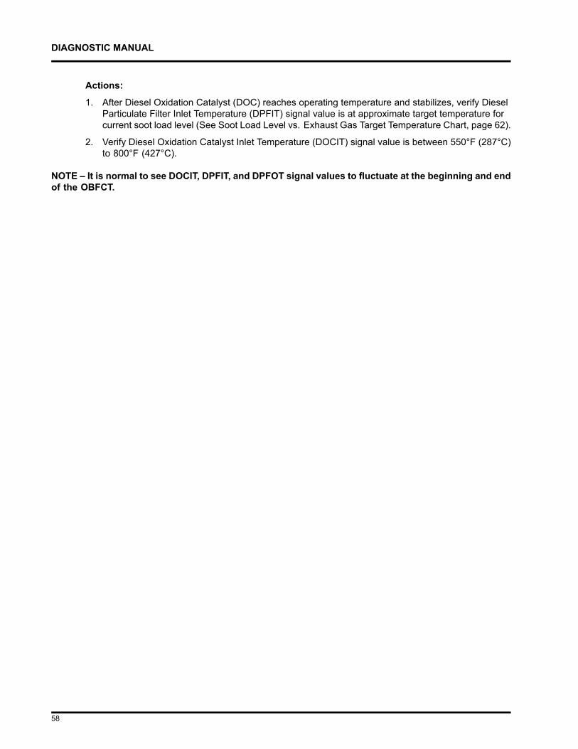
DIAGNOSTIC MANUAL
Actions:
1. After Diesel Oxidation Catalyst (DOC) reaches operating temperature and stabilizes, verify DieselParticulate Filter Inlet Temperature (DPFIT) signal value is at approximate target temperature forcurrent soot load level (See Soot Load Level vs. Exhaust Gas Target Temperature Chart, page 62).
2. Verify Diesel Oxidation Catalyst Inlet Temperature (DOCIT) signal value is between 550°F (287°C)to 800°F (427°C).
NOTE – It is normal to see DOCIT, DPFIT, and DPFOT signal values to fluctuate at the beginning and endof the OBFCT.
58
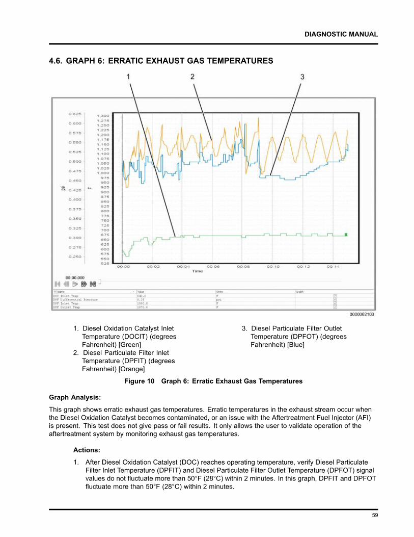
DIAGNOSTIC MANUAL
4.6. GRAPH 6: ERRATIC EXHAUST GAS TEMPERATURES
1. Diesel Oxidation Catalyst InletTemperature (DOCIT) (degreesFahrenheit) [Green]
2. Diesel Particulate Filter InletTemperature (DPFIT) (degreesFahrenheit) [Orange]
3. Diesel Particulate Filter OutletTemperature (DPFOT) (degreesFahrenheit) [Blue]
Figure 10 Graph 6: Erratic Exhaust Gas Temperatures
Graph Analysis:
This graph shows erratic exhaust gas temperatures. Erratic temperatures in the exhaust stream occur whenthe Diesel Oxidation Catalyst becomes contaminated, or an issue with the Aftertreatment Fuel Injector (AFI)is present. This test does not give pass or fail results. It only allows the user to validate operation of theaftertreatment system by monitoring exhaust gas temperatures.
Actions:
1. After Diesel Oxidation Catalyst (DOC) reaches operating temperature, verify Diesel ParticulateFilter Inlet Temperature (DPFIT) and Diesel Particulate Filter Outlet Temperature (DPFOT) signalvalues do not fluctuate more than 50°F (28°C) within 2 minutes. In this graph, DPFIT and DPFOTfluctuate more than 50°F (28°C) within 2 minutes.
59
DIAGNOSTIC MANUAL
4.7. GRAPH 7: LOW EXHAUST GAS TEMPERATURES (RESTRICTED AFI)
NOTE – Snapshot recorded below with Diesel Particulate Filter (DPF) soot load level 1.
1. Diesel Oxidation Catalyst InletTemperature (DOCIT) (degreesFahrenheit) [Blue]
2. Diesel Particulate Filter InletTemperature (DPFIT) (degreesFahrenheit) [Orange]
3. Diesel Particulate Filter OutletTemperature (DPFOT) (degreesFahrenheit) [Green]
Figure 11 Graph 7: Low Exhaust Gas Temperatures (Restricted AFI)
Graph Analysis:
This graph shows low exhaust gas temperatures indicating a restricted Aftertreatment Fuel Injector (AFI). Lowtemperatures in the exhaust stream occur when fuel flow from the AFI is restricted, resulting in less fuel burningin the exhaust stream. This test does not give pass or fail results. It only allows the user to validate operationof the aftertreatment system by monitoring exhaust gas temperatures.
60
DIAGNOSTIC MANUAL
Actions:
1. After Diesel Oxidation Catalyst (DOC) reaches operating temperature and stabilizes, verify DieselParticulate Filter Inlet Temperature (DPFIT) signal value is at approximate target temperature forcurrent soot load level (See Soot Load Level vs. Exhaust Gas Target Temperature Chart, page 62).
2. Verify Diesel Oxidation Catalyst Inlet Temperature (DOCIT) signal value is between 550°F (287°C)to 800°F (427°C).
NOTE – It is normal to see DOCIT, DPFIT, and DPFOT signal values fluctuate at the beginning and endof the OBFCT.
61

DIAGNOSTIC MANUAL
4.8. SOOT LOAD LEVEL VS. EXHAUST GAS TARGET TEMPERATURE CHART
Soot Load (%) DPF Soot Load Level Exhaust Gas Target Temperature(DPFIT)
0 -16 0 1125°F (607°C)
17 -33 1 1110°F (599°C)
34 - 49 2 1090°F (588°C)
50 - 66 3 1075°F (579°C)
67 - 83 4 1050°F (566°C)
84 - 99 5 1025°F (552°C)
100 - 116 6 1000°F (538°C)
117 - 132 7 975°F (524°C)
133 - 149 8 900°F (482°C)
150 - 169 9 860°F (460°C)
170 - 184 10 850°F (454°C)
185 - 199 11 840°F (449°C)
200 - 216 12 835°F (446°C)
217 - 234 13 830°F (443°C)
235 - 249 14 825°F (441°C)
250 - 269 15 820°F (438°C)
270 and above 16 and above 810°F (432°C) or below
62

DIAGNOSTIC MANUAL
AFTERTREATMENT SYSTEM OPERATION5.1. MAXXFORCE® DT, 9 AND 10
The Aftertreatment (AFT) system, part of the larger exhaust system, processes engine exhaust to meetemission requirements. The AFT system traps particulate matter (soot) and prevents it from leaving the tailpipe.
The AFT system performs the following functions:
• Monitors exhaust gas temperatures Diesel Oxidation Catalyst Inlet Temperature (DOCIT), Diesel OxidationCatalyst Outlet Temperature (DOCOT), and Diesel Particulate Filter Outlet Temperature (DPFOT).
• Monitors Diesel Particulate Filter Differential Pressure (DPFDP).
• Controls engine operating parameters for emission control and failure recognition.
• Cancels regeneration of the AFT system in the event of catalyst or sensor failure.
• Calculates the level of ash accumulation in the Diesel Particulate Filter (DPF).
• Initiates regeneration of the AFT system when DPF soot load is too high by increasing exhaust gastemperatures.
• Maintains vehicle and engine performance during regeneration.
63
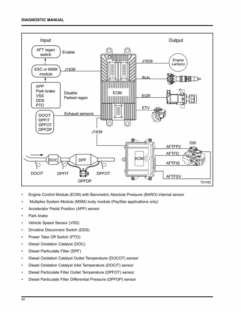
DIAGNOSTIC MANUAL
• Engine Control Module (ECM) with Barometric Absolute Pressure (BARO) internal sensor
• Multiplex System Module (MSM) body module (PayStar applications only)
• Accelerator Pedal Position (APP) sensor
• Park brake
• Vehicle Speed Sensor (VSS)
• Driveline Disconnect Switch (DDS)
• Power Take Off Switch (PTO)
• Diesel Oxidation Catalyst (DOC)
• Diesel Particulate Filter (DPF)
• Diesel Oxidation Catalyst Outlet Temperature (DOCOT) sensor
• Diesel Oxidation Catalyst Inlet Temperature (DOCIT) sensor
• Diesel Particulate Filter Outlet Temperature (DPFOT) sensor
• Diesel Particulate Filter Differential Pressure (DPFDP) sensor
64
DIAGNOSTIC MANUAL
• Fuel Injectors (INJs)
• Exhaust Gas Recirculation (EGR) valve
• Engine Throttle Valve (ETV)
• Warning Indicators
• Inlet Air Heater (IAH)
• Aftertreatment Control Module (ACM)
• Aftertreatment Fuel Inlet Sensor (AFTFIS)
• Aftertreatment Fuel Pressure 2 (AFTFP2) sensor
• Aftertreatment Fuel Shutoff Valve (AFTFSV)
• Aftertreatment Fuel Doser (AFTFD)
• Downstream Injection (DSI) unit
65
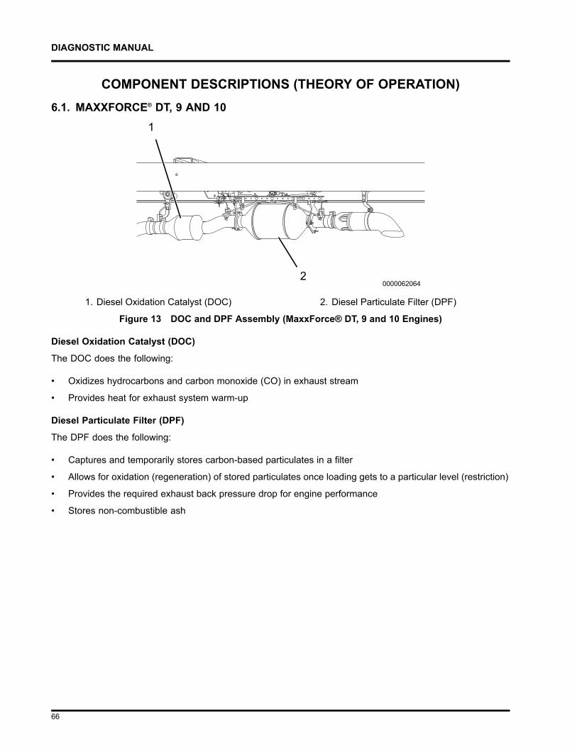
DIAGNOSTIC MANUAL
COMPONENT DESCRIPTIONS (THEORY OF OPERATION)6.1. MAXXFORCE® DT, 9 AND 10
1. Diesel Oxidation Catalyst (DOC) 2. Diesel Particulate Filter (DPF)
Figure 13 DOC and DPF Assembly (MaxxForce® DT, 9 and 10 Engines)
Diesel Oxidation Catalyst (DOC)
The DOC does the following:
• Oxidizes hydrocarbons and carbon monoxide (CO) in exhaust stream
• Provides heat for exhaust system warm-up
Diesel Particulate Filter (DPF)
The DPF does the following:
• Captures and temporarily stores carbon-based particulates in a filter
• Allows for oxidation (regeneration) of stored particulates once loading gets to a particular level (restriction)
• Provides the required exhaust back pressure drop for engine performance
• Stores non-combustible ash
66

DIAGNOSTIC MANUAL
1. Downstream Injection (DSI) unit
Figure 14 DSI Unit (MaxxForce® DT, 9 and 10 Engines)
Downstream Injection (DSI) Unit
The DSI unit is connected to the clean side of the low-pressure fuel system, and will provide a meteredamount of fuel to the Aftertreatment Fuel Injector (AFI). The DSI unit provides pressurized fuel injection pulsesto the AFI. The AFI is a mechanical poppet type injector, and will only inject fuel when fuel line pressureis increased above a specific pressure.
67
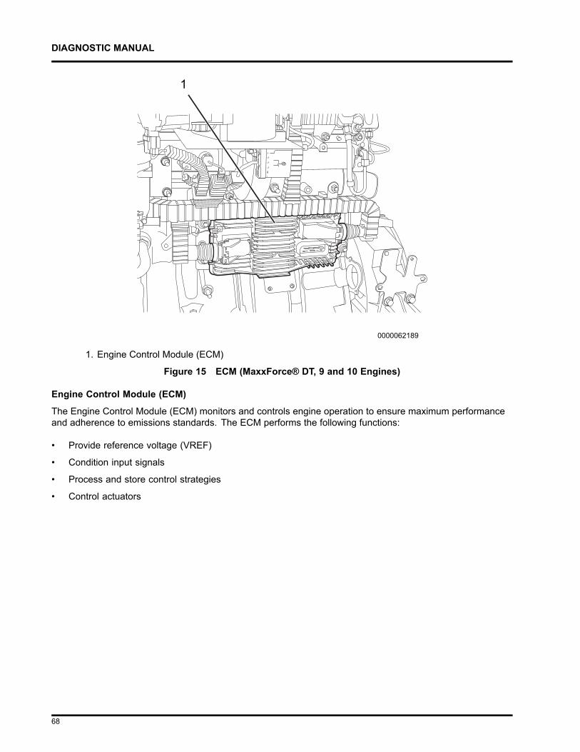
DIAGNOSTIC MANUAL
1. Engine Control Module (ECM)
Figure 15 ECM (MaxxForce® DT, 9 and 10 Engines)
Engine Control Module (ECM)
The Engine Control Module (ECM) monitors and controls engine operation to ensure maximum performanceand adherence to emissions standards. The ECM performs the following functions:
• Provide reference voltage (VREF)
• Condition input signals
• Process and store control strategies
• Control actuators
68
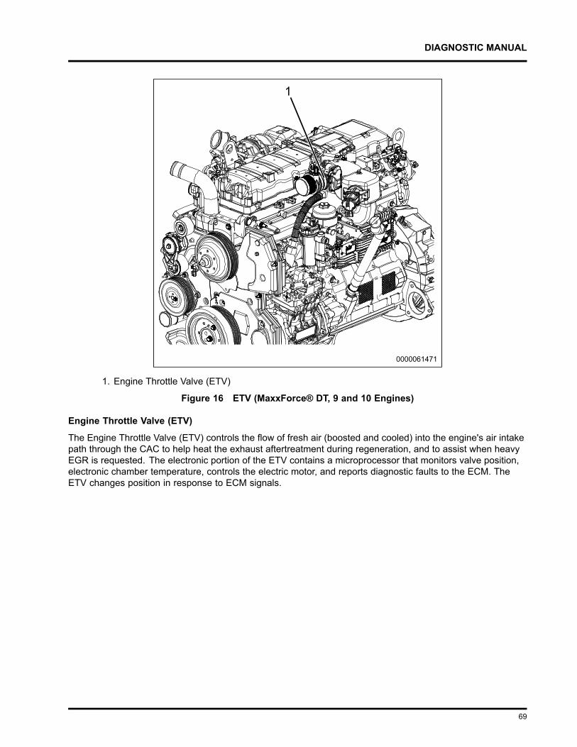
DIAGNOSTIC MANUAL
1. Engine Throttle Valve (ETV)
Figure 16 ETV (MaxxForce® DT, 9 and 10 Engines)
Engine Throttle Valve (ETV)
The Engine Throttle Valve (ETV) controls the flow of fresh air (boosted and cooled) into the engine's air intakepath through the CAC to help heat the exhaust aftertreatment during regeneration, and to assist when heavyEGR is requested. The electronic portion of the ETV contains a microprocessor that monitors valve position,electronic chamber temperature, controls the electric motor, and reports diagnostic faults to the ECM. TheETV changes position in response to ECM signals.
69
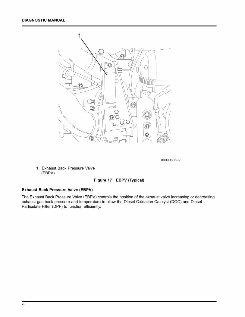
DIAGNOSTIC MANUAL
1. Exhaust Back Pressure Valve(EBPV)
Figure 17 EBPV (Typical)
Exhaust Back Pressure Valve (EBPV)
The Exhaust Back Pressure Valve (EBPV) controls the position of the exhaust valve increasing or decreasingexhaust gas back pressure and temperature to allow the Diesel Oxidation Catalyst (DOC) and DieselParticulate Filter (DPF) to function efficiently.
70
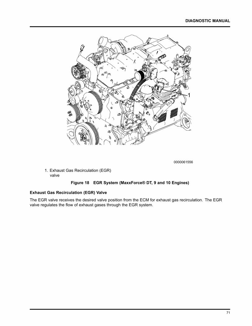
DIAGNOSTIC MANUAL
1. Exhaust Gas Recirculation (EGR)valve
Figure 18 EGR System (MaxxForce® DT, 9 and 10 Engines)
Exhaust Gas Recirculation (EGR) Valve
The EGR valve receives the desired valve position from the ECM for exhaust gas recirculation. The EGRvalve regulates the flow of exhaust gases through the EGR system.
71
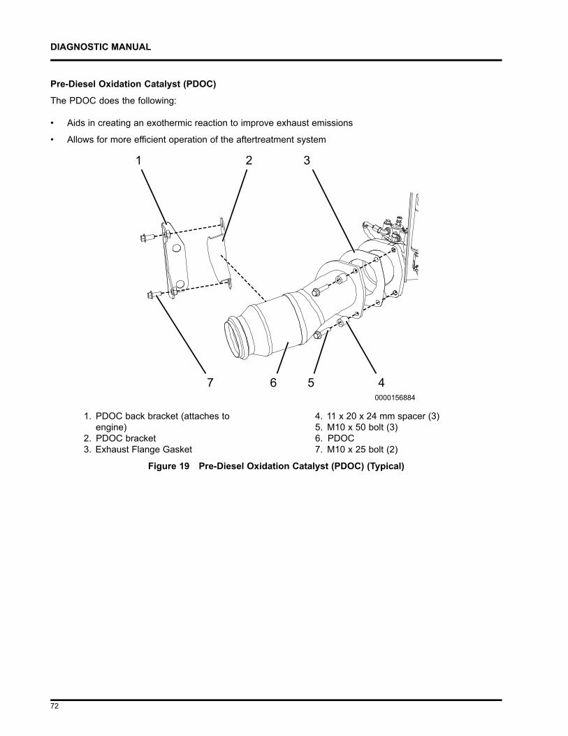
DIAGNOSTIC MANUAL
Pre-Diesel Oxidation Catalyst (PDOC)
The PDOC does the following:
• Aids in creating an exothermic reaction to improve exhaust emissions
• Allows for more efficient operation of the aftertreatment system
1. PDOC back bracket (attaches toengine)
2. PDOC bracket3. Exhaust Flange Gasket
4. 11 x 20 x 24 mm spacer (3)5. M10 x 50 bolt (3)6. PDOC7. M10 x 25 bolt (2)
Figure 19 Pre-Diesel Oxidation Catalyst (PDOC) (Typical)
72
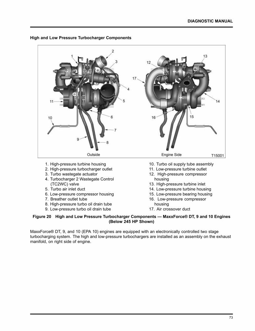
DIAGNOSTIC MANUAL
High and Low Pressure Turbocharger Components
1. High-pressure turbine housing2. High-pressure turbocharger outlet3. Turbo wastegate actuator4. Turbocharger 2 Wastegate Control
(TC2WC) valve5. Turbo air inlet duct6. Low-pressure compressor housing7. Breather outlet tube8. High-pressure turbo oil drain tube9. Low-pressure turbo oil drain tube
10. Turbo oil supply tube assembly11. Low-pressure turbine outlet12. High-pressure compressor
housing13. High-pressure turbine inlet14. Low-pressure turbine housing15. Low-pressure bearing housing16. Low-pressure compressor
housing17. Air crossover duct
Figure 20 High and Low Pressure Turbocharger Components — MaxxForce® DT, 9 and 10 Engines(Below 245 HP Shown)
MaxxForce® DT, 9, and 10 (EPA 10) engines are equipped with an electronically controlled two stageturbocharging system. The high and low-pressure turbochargers are installed as an assembly on the exhaustmanifold, on right side of engine.
73
DIAGNOSTIC MANUAL
Intake air flow: Filtered air enters the LP compressor, where it is compressed and directed to the LPCAC(if equipped). Cooled LP air enters the HP compressor where it is further compressed and directed into theHPCAC. Compressed air then travels through the ETV and the intake throttle duct. This system provides highcharge air pressure to improve engine performance and to help reduce emissions.
Exhaust gas flow: The HP turbocharger is connected directly to the exhaust manifold through the HP turbineinlet. Exhaust gases exit the HP turbine outlet and are directed to the LP turbine inlet. The HP turbocharger isequipped with a single wastegate, which is controlled by pneumatic actuator. When boost demand is low, thewastegate is opened, allowing part of the exhaust gas flow to bypass the turbine.
74
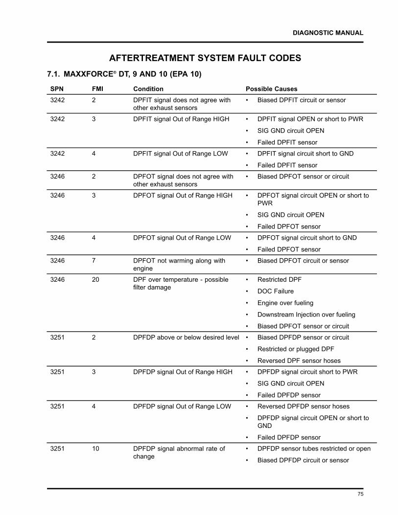
DIAGNOSTIC MANUAL
AFTERTREATMENT SYSTEM FAULT CODES7.1. MAXXFORCE® DT, 9 AND 10 (EPA 10)
SPN FMI Condition Possible Causes3242 2 DPFIT signal does not agree with
other exhaust sensors• Biased DPFIT circuit or sensor
3242 3 DPFIT signal Out of Range HIGH • DPFIT signal OPEN or short to PWR
• SIG GND circuit OPEN
• Failed DPFIT sensor
3242 4 DPFIT signal Out of Range LOW • DPFIT signal circuit short to GND
• Failed DPFIT sensor
3246 2 DPFOT signal does not agree withother exhaust sensors
• Biased DPFOT sensor or circuit
3246 3 DPFOT signal Out of Range HIGH • DPFOT signal circuit OPEN or short toPWR
• SIG GND circuit OPEN
• Failed DPFOT sensor
3246 4 DPFOT signal Out of Range LOW • DPFOT signal circuit short to GND
• Failed DPFOT sensor
3246 7 DPFOT not warming along withengine
• Biased DPFOT circuit or sensor
3246 20 DPF over temperature - possiblefilter damage
• Restricted DPF
• DOC Failure
• Engine over fueling
• Downstream Injection over fueling
• Biased DPFOT sensor or circuit
3251 2 DPFDP above or below desired level • Biased DPFDP sensor or circuit
• Restricted or plugged DPF
• Reversed DPF sensor hoses
3251 3 DPFDP signal Out of Range HIGH • DPFDP signal circuit short to PWR
• SIG GND circuit OPEN
• Failed DPFDP sensor
3251 4 DPFDP signal Out of Range LOW • Reversed DPFDP sensor hoses
• DPFDP signal circuit OPEN or short toGND
• Failed DPFDP sensor
3251 10 DPFDP signal abnormal rate ofchange
• DPFDP sensor tubes restricted or open
• Biased DPFDP circuit or sensor
75
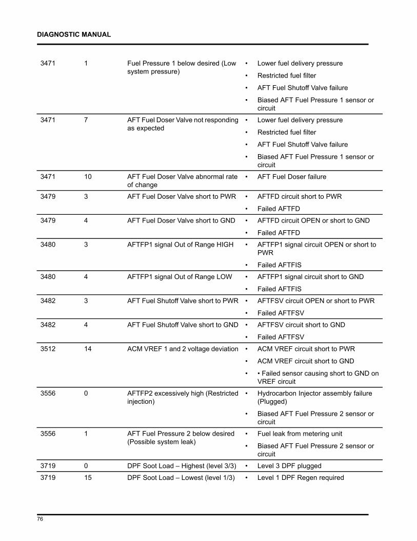
DIAGNOSTIC MANUAL
3471 1 Fuel Pressure 1 below desired (Lowsystem pressure)
• Lower fuel delivery pressure
• Restricted fuel filter
• AFT Fuel Shutoff Valve failure
• Biased AFT Fuel Pressure 1 sensor orcircuit
3471 7 AFT Fuel Doser Valve not respondingas expected
• Lower fuel delivery pressure
• Restricted fuel filter
• AFT Fuel Shutoff Valve failure
• Biased AFT Fuel Pressure 1 sensor orcircuit
3471 10 AFT Fuel Doser Valve abnormal rateof change
• AFT Fuel Doser failure
3479 3 AFT Fuel Doser Valve short to PWR • AFTFD circuit short to PWR
• Failed AFTFD
3479 4 AFT Fuel Doser Valve short to GND • AFTFD circuit OPEN or short to GND
• Failed AFTFD
3480 3 AFTFP1 signal Out of Range HIGH • AFTFP1 signal circuit OPEN or short toPWR
• Failed AFTFIS
3480 4 AFTFP1 signal Out of Range LOW • AFTFP1 signal circuit short to GND
• Failed AFTFIS
3482 3 AFT Fuel Shutoff Valve short to PWR • AFTFSV circuit OPEN or short to PWR
• Failed AFTFSV
3482 4 AFT Fuel Shutoff Valve short to GND • AFTFSV circuit short to GND
• Failed AFTFSV
3512 14 ACM VREF 1 and 2 voltage deviation • ACM VREF circuit short to PWR
• ACM VREF circuit short to GND
• • Failed sensor causing short to GND onVREF circuit
3556 0 AFTFP2 excessively high (Restrictedinjection)
• Hydrocarbon Injector assembly failure(Plugged)
• Biased AFT Fuel Pressure 2 sensor orcircuit
3556 1 AFT Fuel Pressure 2 below desired(Possible system leak)
• Fuel leak from metering unit
• Biased AFT Fuel Pressure 2 sensor orcircuit
3719 0 DPF Soot Load – Highest (level 3/3) • Level 3 DPF plugged
3719 15 DPF Soot Load – Lowest (level 1/3) • Level 1 DPF Regen required
76
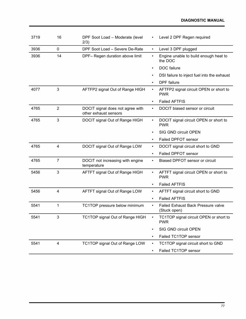
DIAGNOSTIC MANUAL
3719 16 DPF Soot Load – Moderate (level2/3)
• Level 2 DPF Regen required
3936 0 DPF Soot Load – Severe De-Rate • Level 3 DPF plugged
3936 14 DPF– Regen duration above limit • Engine unable to build enough heat tothe DOC
• DOC failure
• DSI failure to inject fuel into the exhaust
• DPF failure
4077 3 AFTFP2 signal Out of Range HIGH • AFTFP2 signal circuit OPEN or short toPWR
• Failed AFTFIS
4765 2 DOCIT signal does not agree withother exhaust sensors
• DOCIT biased sensor or circuit
4765 3 DOCIT signal Out of Range HIGH • DOCIT signal circuit OPEN or short toPWR
• SIG GND circuit OPEN
• Failed DPFOT sensor
4765 4 DOCIT signal Out of Range LOW • DOCIT signal circuit short to GND
• Failed DPFOT sensor
4765 7 DOCIT not increasing with enginetemperature
• Biased DPFOT sensor or circuit
5456 3 AFTFT signal Out of Range HIGH • AFTFT signal circuit OPEN or short toPWR
• Failed AFTFIS
5456 4 AFTFT signal Out of Range LOW • AFTFT signal circuit short to GND
• Failed AFTFIS
5541 1 TC1TOP pressure below minimum • Failed Exhaust Back Pressure valve(Stuck open)
5541 3 TC1TOP signal Out of Range HIGH • TC1TOP signal circuit OPEN or short toPWR
• SIG GND circuit OPEN
• Failed TC1TOP sensor
5541 4 TC1TOP signal Out of Range LOW • TC1TOP signal circuit short to GND
• Failed TC1TOP sensor
77
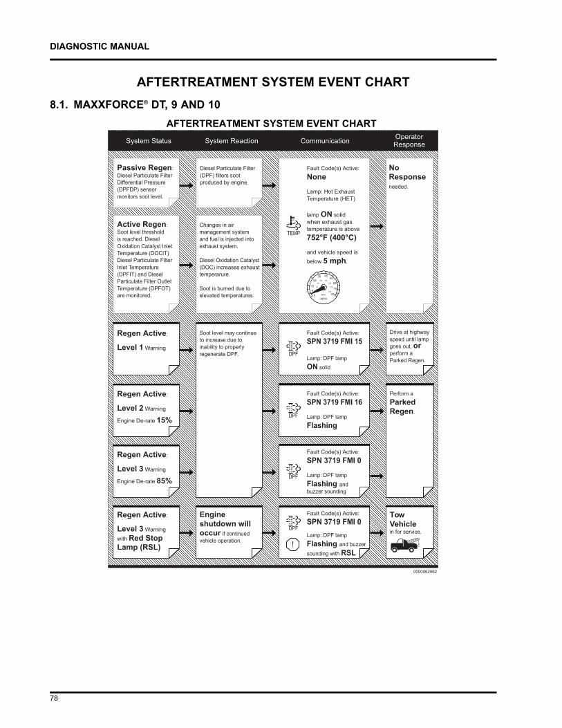
DIAGNOSTIC MANUAL
AFTERTREATMENT SYSTEM EVENT CHART8.1. MAXXFORCE® DT, 9 AND 10
78
DIAGNOSTIC MANUAL
MAXXFORCE® 11,13 AND 15 AFTERTREATMENT SYSTEM DIAGNOSTICS9.1. START DIAGNOSTICS HERE: ENGINE AND AFTERTREATMENT SYSTEMOPERATIONAL CHECKS
Overview
A properly operating aftertreatment system requires little manual intervention from the operator. Illuminatedwarning lamps indicate a driving or extended idle operation that may not allow a successful regeneration of theaftertreatment system. These illuminated warning lamps may indicate an engine mechanical or performanceconcern.
Tools Required
• Electronic Service Tool (EST) with ServiceMaxx™ software
• Interface cable (RP1210B compliant supporting J1939 and J1708)
NOTE – A frequent regen concern may not be repaired by only performing an Onboard Filter CleanlinessTest (OBFCT). Perform all steps in the following diagnostic procedure in order to identify root causefailure.
NOTE – Repair all active fault code(s) other than SPN 3719 (DPF Soot Load) before beginning Engineand Aftertreatment System Operational Checks.
79
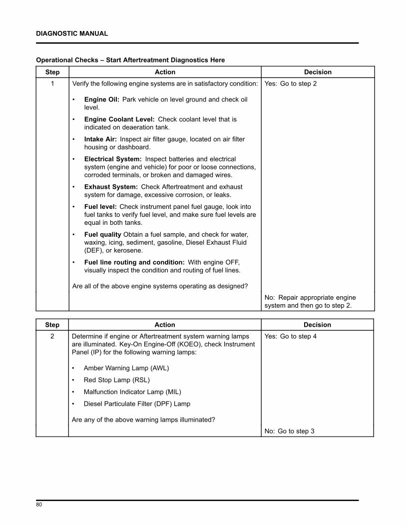
DIAGNOSTIC MANUAL
Operational Checks – Start Aftertreatment Diagnostics Here
Step Action Decision1 Verify the following engine systems are in satisfactory condition:
• Engine Oil: Park vehicle on level ground and check oillevel.
• Engine Coolant Level: Check coolant level that isindicated on deaeration tank.
• Intake Air: Inspect air filter gauge, located on air filterhousing or dashboard.
• Electrical System: Inspect batteries and electricalsystem (engine and vehicle) for poor or loose connections,corroded terminals, or broken and damaged wires.
• Exhaust System: Check Aftertreatment and exhaustsystem for damage, excessive corrosion, or leaks.
• Fuel level: Check instrument panel fuel gauge, look intofuel tanks to verify fuel level, and make sure fuel levels areequal in both tanks.
• Fuel quality Obtain a fuel sample, and check for water,waxing, icing, sediment, gasoline, Diesel Exhaust Fluid(DEF), or kerosene.
• Fuel line routing and condition: With engine OFF,visually inspect the condition and routing of fuel lines.
Are all of the above engine systems operating as designed?
Yes: Go to step 2
No: Repair appropriate enginesystem and then go to step 2.
Step Action Decision2 Determine if engine or Aftertreatment system warning lamps
are illuminated. Key-On Engine-Off (KOEO), check InstrumentPanel (IP) for the following warning lamps:
• Amber Warning Lamp (AWL)
• Red Stop Lamp (RSL)
• Malfunction Indicator Lamp (MIL)
• Diesel Particulate Filter (DPF) Lamp
Are any of the above warning lamps illuminated?
Yes: Go to step 4
No: Go to step 3
80
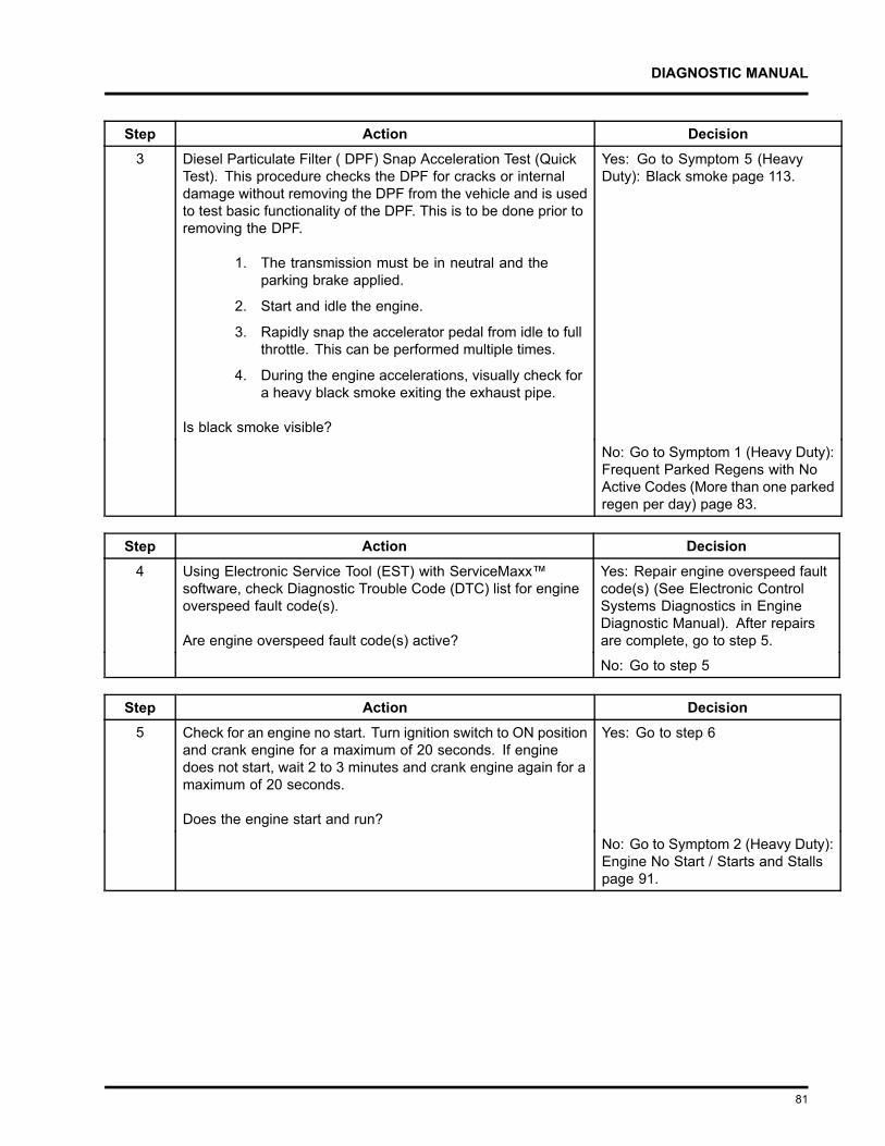
DIAGNOSTIC MANUAL
Step Action Decision3 Diesel Particulate Filter ( DPF) Snap Acceleration Test (Quick
Test). This procedure checks the DPF for cracks or internaldamage without removing the DPF from the vehicle and is usedto test basic functionality of the DPF. This is to be done prior toremoving the DPF.
1. The transmission must be in neutral and theparking brake applied.
2. Start and idle the engine.
3. Rapidly snap the accelerator pedal from idle to fullthrottle. This can be performed multiple times.
4. During the engine accelerations, visually check fora heavy black smoke exiting the exhaust pipe.
Is black smoke visible?
Yes: Go to Symptom 5 (HeavyDuty): Black smoke page 113.
No: Go to Symptom 1 (Heavy Duty):Frequent Parked Regens with NoActive Codes (More than one parkedregen per day) page 83.
Step Action Decision4 Using Electronic Service Tool (EST) with ServiceMaxx™
software, check Diagnostic Trouble Code (DTC) list for engineoverspeed fault code(s).
Are engine overspeed fault code(s) active?
Yes: Repair engine overspeed faultcode(s) (See Electronic ControlSystems Diagnostics in EngineDiagnostic Manual). After repairsare complete, go to step 5.
No: Go to step 5
Step Action Decision5 Check for an engine no start. Turn ignition switch to ON position
and crank engine for a maximum of 20 seconds. If enginedoes not start, wait 2 to 3 minutes and crank engine again for amaximum of 20 seconds.
Does the engine start and run?
Yes: Go to step 6
No: Go to Symptom 2 (Heavy Duty):Engine No Start / Starts and Stallspage 91.
81
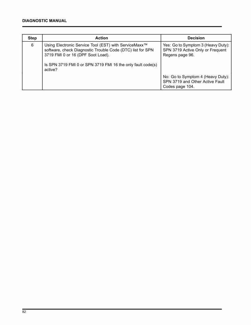
DIAGNOSTIC MANUAL
Step Action Decision6 Using Electronic Service Tool (EST) with ServiceMaxx™
software, check Diagnostic Trouble Code (DTC) list for SPN3719 FMI 0 or 16 (DPF Soot Load).
Is SPN 3719 FMI 0 or SPN 3719 FMI 16 the only fault code(s)active?
Yes: Go to Symptom 3 (Heavy Duty):SPN 3719 Active Only or FrequentRegens page 96.
No: Go to Symptom 4 (Heavy Duty):SPN 3719 and Other Active FaultCodes page 104.
82
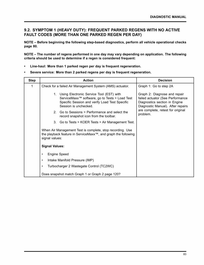
DIAGNOSTIC MANUAL
9.2. SYMPTOM 1 (HEAVY DUTY): FREQUENT PARKED REGENS WITH NO ACTIVEFAULT CODES (MORE THAN ONE PARKED REGEN PER DAY)
NOTE – Before beginning the following step-based diagnostics, perform all vehicle operational checkspage 80.
NOTE – The number of regens performed in one day may vary depending on application. The followingcriteria should be used to determine if a regen is considered frequent:
• Line-haul: More than 1 parked regen per day is frequent regeneration.
• Severe service: More than 2 parked regens per day is frequent regeneration.
Step Action Decision1 Check for a failed Air Management System (AMS) actuator.
1. Using Electronic Service Tool (EST) withServiceMaxx™ software, go to Tests > Load TestSpecific Session and verify Load Test SpecificSession is unchecked.
2. Go to Sessions > Performance and select therecord snapshot icon from the toolbar.
3. Go to Tests > KOER Tests > Air Management Test.
When Air Management Test is complete, stop recording. Usethe playback feature in ServiceMaxx™, and graph the followingsignal values:
Signal Values:
• Engine Speed
• Intake Manifold Pressure (IMP)
• Turbocharger 2 Wastegate Control (TC2WC)
Does snapshot match Graph 1 or Graph 2 page 120?
Graph 1: Go to step 2A
Graph 2: Diagnose and repairfailed actuator (See PerformanceDiagnostics section in EngineDiagnostic Manual). After repairsare complete, retest for originalproblem.
83
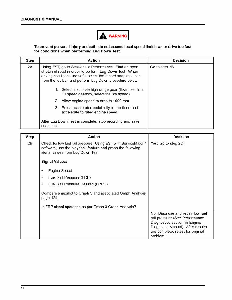
DIAGNOSTIC MANUAL
WARNING
To prevent personal injury or death, do not exceed local speed limit laws or drive too fastfor conditions when performing Lug Down Test.
Step Action Decision2A Using EST, go to Sessions > Performance. Find an open
stretch of road in order to perform Lug Down Test. Whendriving conditions are safe, select the record snapshot iconfrom the toolbar, and perform Lug Down procedure below:
1. Select a suitable high range gear (Example: In a10 speed gearbox, select the 8th speed).
2. Allow engine speed to drop to 1000 rpm.
3. Press accelerator pedal fully to the floor, andaccelerate to rated engine speed.
After Lug Down Test is complete, stop recording and savesnapshot.
Go to step 2B
Step Action Decision2B Check for low fuel rail pressure. Using EST with ServiceMaxx™
software, use the playback feature and graph the followingsignal values from Lug Down Test:
Signal Values:
• Engine Speed
• Fuel Rail Pressure (FRP)
• Fuel Rail Pressure Desired (FRPD)
Compare snapshot to Graph 3 and associated Graph Analysispage 124.
Is FRP signal operating as per Graph 3 Graph Analysis?
Yes: Go to step 2C
No: Diagnose and repair low fuelrail pressure (See PerformanceDiagnostics section in EngineDiagnostic Manual). After repairsare complete, retest for originalproblem.
84
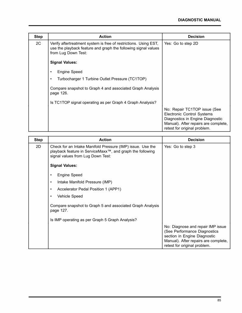
DIAGNOSTIC MANUAL
Step Action Decision2C Verify aftertreatment system is free of restrictions. Using EST,
use the playback feature and graph the following signal valuesfrom Lug Down Test:
Signal Values:
• Engine Speed
• Turbocharger 1 Turbine Outlet Pressure (TC1TOP)
Compare snapshot to Graph 4 and associated Graph Analysispage 126.
Is TC1TOP signal operating as per Graph 4 Graph Analysis?
Yes: Go to step 2D
No: Repair TC1TOP issue (SeeElectronic Control SystemsDiagnostics in Engine DiagnosticManual). After repairs are complete,retest for original problem.
Step Action Decision2D Check for an Intake Manifold Pressure (IMP) issue. Use the
playback feature in ServiceMaxx™, and graph the followingsignal values from Lug Down Test:
Signal Values:
• Engine Speed
• Intake Manifold Pressure (IMP)
• Accelerator Pedal Position 1 (APP1)
• Vehicle Speed
Compare snapshot to Graph 5 and associated Graph Analysispage 127.
Is IMP operating as per Graph 5 Graph Analysis?
Yes: Go to step 3
No: Diagnose and repair IMP issue(See Performance Diagnosticssection in Engine DiagnosticManual). After repairs are complete,retest for original problem.
85
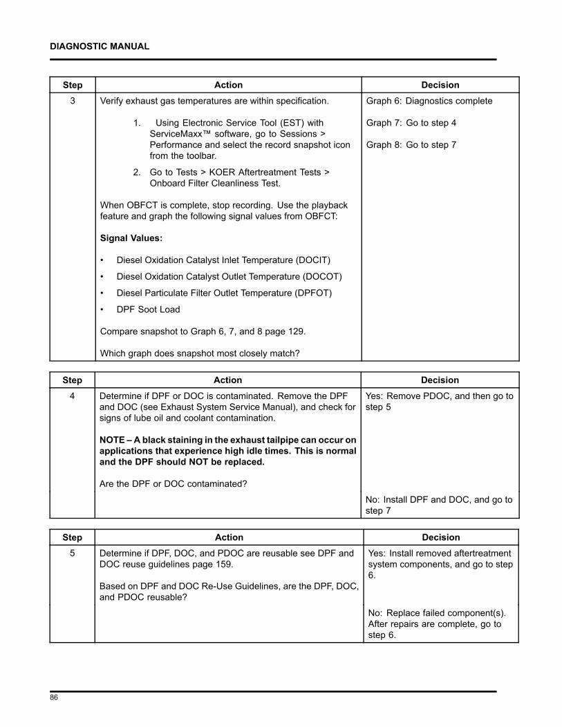
DIAGNOSTIC MANUAL
Step Action Decision3 Verify exhaust gas temperatures are within specification.
1. Using Electronic Service Tool (EST) withServiceMaxx™ software, go to Sessions >Performance and select the record snapshot iconfrom the toolbar.
2. Go to Tests > KOER Aftertreatment Tests >Onboard Filter Cleanliness Test.
When OBFCT is complete, stop recording. Use the playbackfeature and graph the following signal values from OBFCT:
Signal Values:
• Diesel Oxidation Catalyst Inlet Temperature (DOCIT)
• Diesel Oxidation Catalyst Outlet Temperature (DOCOT)
• Diesel Particulate Filter Outlet Temperature (DPFOT)
• DPF Soot Load
Compare snapshot to Graph 6, 7, and 8 page 129.
Which graph does snapshot most closely match?
Graph 6: Diagnostics complete
Graph 7: Go to step 4
Graph 8: Go to step 7
Step Action Decision4 Determine if DPF or DOC is contaminated. Remove the DPF
and DOC (see Exhaust System Service Manual), and check forsigns of lube oil and coolant contamination.
NOTE – A black staining in the exhaust tailpipe can occur onapplications that experience high idle times. This is normaland the DPF should NOT be replaced.
Are the DPF or DOC contaminated?
Yes: Remove PDOC, and then go tostep 5
No: Install DPF and DOC, and go tostep 7
Step Action Decision5 Determine if DPF, DOC, and PDOC are reusable see DPF and
DOC reuse guidelines page 159.
Based on DPF and DOC Re-Use Guidelines, are the DPF, DOC,and PDOC reusable?
Yes: Install removed aftertreatmentsystem components, and go to step6.
No: Replace failed component(s).After repairs are complete, go tostep 6.
86
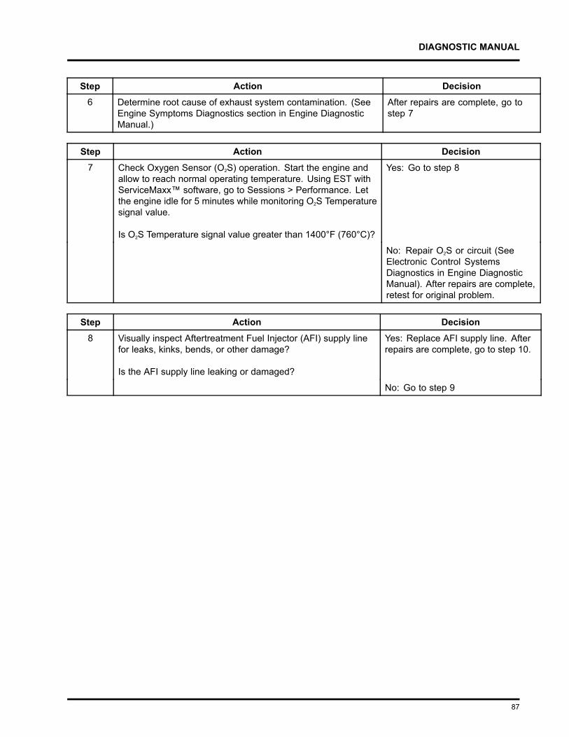
DIAGNOSTIC MANUAL
Step Action Decision6 Determine root cause of exhaust system contamination. (See
Engine Symptoms Diagnostics section in Engine DiagnosticManual.)
After repairs are complete, go tostep 7
Step Action Decision7 Check Oxygen Sensor (O2S) operation. Start the engine and
allow to reach normal operating temperature. Using EST withServiceMaxx™ software, go to Sessions > Performance. Letthe engine idle for 5 minutes while monitoring O2S Temperaturesignal value.
Is O2S Temperature signal value greater than 1400°F (760°C)?
Yes: Go to step 8
No: Repair O2S or circuit (SeeElectronic Control SystemsDiagnostics in Engine DiagnosticManual). After repairs are complete,retest for original problem.
Step Action Decision8 Visually inspect Aftertreatment Fuel Injector (AFI) supply line
for leaks, kinks, bends, or other damage?
Is the AFI supply line leaking or damaged?
Yes: Replace AFI supply line. Afterrepairs are complete, go to step 10.
No: Go to step 9
87
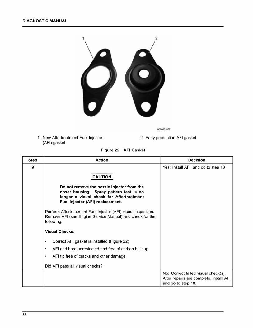
DIAGNOSTIC MANUAL
1. New Aftertreatment Fuel Injector(AFI) gasket
2. Early production AFI gasket
Figure 22 AFI Gasket
Step Action Decision9
CAUTION
Do not remove the nozzle injector from thedoser housing. Spray pattern test is nolonger a visual check for AftertreatmentFuel Injector (AFI) replacement.
Perform Aftertreatment Fuel Injector (AFI) visual inspection.Remove AFI (see Engine Service Manual) and check for thefollowing:
Visual Checks:
• Correct AFI gasket is installed (Figure 22)
• AFI and bore unrestricted and free of carbon buildup
• AFI tip free of cracks and other damage
Did AFI pass all visual checks?
Yes: Install AFI, and go to step 10
No: Correct failed visual check(s).After repairs are complete, install AFIand go to step 10.
88
DIAGNOSTIC MANUAL
Step Action Decision10 Run DSI System De-Aeration Procedure twice, to purge the
Down Stream Injection (DSI) system of air. Using EST, go toProcedures > KOER Aftertreatment Procedures > DSI SystemDe-Aeration.
After procedure is complete, go tostep 11
Step Action Decision11 Using EST, check Diagnostic Trouble Code (DTC) list for fault
code(s) that may have become active during OBFCT.
Does DTC list contain active fault code(s)?
Yes: Repair active fault code(s)(See Electronic Control SystemsDiagnostics in Engine DiagnosticManual). After repairs are complete,go to step 12.
No: Go to step 12
Step Action Decision12 Verify exhaust gas temperatures are within specification.
1. Using Electronic Service Tool (EST) withServiceMaxx™ software, go to Sessions >Performance and select the record snapshot iconfrom the toolbar.
2. Go to Tests > KOER Aftertreatment Tests >Onboard Filter Cleanliness Test.
When OBFCT is complete, stop recording. Use the playbackfeature and graph the following signal values from OBFCT:
Signal Values:
• Diesel Oxidation Catalyst Inlet Temperature (DOCIT)
• Diesel Oxidation Catalyst Outlet Temperature (DOCOT)
• Diesel Particulate Filter Outlet Temperature (DPFOT)
• DPF Soot Load
Compare snapshot to Graphs 7 and 8 page 131.
Which graph does snapshot most closely match?
Graph 7: Go to step 13
Graph 8: After repairs are complete,retest for original problem.
89
DIAGNOSTIC MANUAL
Step Action Decision13 Verify root cause of frequent regens has been diagnosed and
repaired.
Has root cause for frequent regens been diagnosed andrepaired?
Yes: Diagnostics complete
No: Go back to step 1 of Engine andAftertreatment System OperationalChecks page 80 to verify enginesystems are in satisfactory condition.
90
DIAGNOSTIC MANUAL
9.3. SYMPTOM 2 (HEAVY DUTY): ENGINE NO START / STARTS AND STALLS
NOTE – Before beginning the following step-based diagnostics, perform all vehicle operational checkspage 80.
Step Action Decision1 Check for an exhaust system restriction by performing the
following Exhaust System Restriction Test:
CAUTION
To prevent damage to the starter, if enginefails to start within 20 seconds, releaseignition switch and wait 2 to 3 minutes toallow starter motor to cool.
1. Turn ignition switch to ON position.
2. Using Electronic Service Tool (EST) withServiceMaxx™ software, go to Sessions >Performance and select the record snapshot iconfrom the toolbar.
3. Crank the engine for a maximum of 20 secondsand then stop recording.
4. Use the playback feature in ServiceMaxx™and graph Turbocharger 1 Turbine OutletPressure (TC1TOP), and Diesel Particulate FilterDifferential Pressure (DPFDP) signal values.
5. Verify DPFDP and TC1TOP are withinspecification. DPFDP signal value should be lessthan 1 psi (7 kPa), and TC1TOP signal valueshould be less than 5 psi (34 kPa).
Are DPFDP and TC1TOP signal values within specification?
Both DPFDP and TC1TOP signalsHigh: Go to step 2
TC1TOP signal High Only: Go to step3
Neither DPFDP or TC1TOP signalHigh: Go to Hard Start and NoStart Diagnostics section in EngineDiagnostic Manual. After repairs arecomplete, go to step 7.
Step Action Decision2 Determine if Diesel Particulate Filter (DPF) is contaminated.
Remove the DPF (see Exhaust System Service Manual), andcheck for signs of lube oil and coolant contamination.
NOTE – A black staining in the exhaust tailpipe can occuron applications that experience high idle times. This isnormal and the DPF should NOT be replaced.
Is the DPF contaminated?
Yes: Remove Pre-Diesel OxidationCatalyst (PDOC) and Diesel OxidationCatalyst (DOC), and then go to step 4.
No: Go to step 5
91
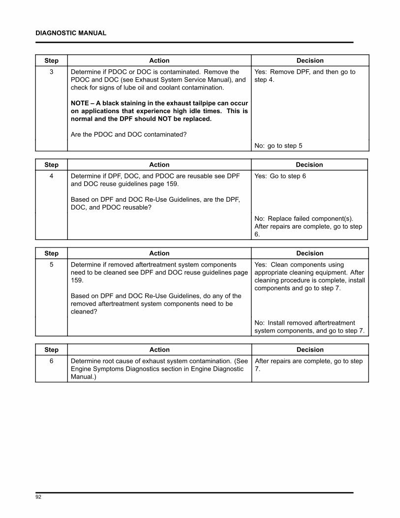
DIAGNOSTIC MANUAL
Step Action Decision3 Determine if PDOC or DOC is contaminated. Remove the
PDOC and DOC (see Exhaust System Service Manual), andcheck for signs of lube oil and coolant contamination.
NOTE – A black staining in the exhaust tailpipe can occuron applications that experience high idle times. This isnormal and the DPF should NOT be replaced.
Are the PDOC and DOC contaminated?
Yes: Remove DPF, and then go tostep 4.
No: go to step 5
Step Action Decision4 Determine if DPF, DOC, and PDOC are reusable see DPF
and DOC reuse guidelines page 159.
Based on DPF and DOC Re-Use Guidelines, are the DPF,DOC, and PDOC reusable?
Yes: Go to step 6
No: Replace failed component(s).After repairs are complete, go to step6.
Step Action Decision5 Determine if removed aftertreatment system components
need to be cleaned see DPF and DOC reuse guidelines page159.
Based on DPF and DOC Re-Use Guidelines, do any of theremoved aftertreatment system components need to becleaned?
Yes: Clean components usingappropriate cleaning equipment. Aftercleaning procedure is complete, installcomponents and go to step 7.
No: Install removed aftertreatmentsystem components, and go to step 7.
Step Action Decision6 Determine root cause of exhaust system contamination. (See
Engine Symptoms Diagnostics section in Engine DiagnosticManual.)
After repairs are complete, go to step7.
92
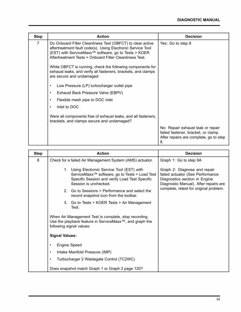
DIAGNOSTIC MANUAL
Step Action Decision7 Do Onboard Filter Cleanliness Test (OBFCT) to clear active
aftertreatment fault code(s). Using Electronic Service Tool(EST) with ServiceMaxx™ software, go to Tests > KOERAftertreatment Tests > Onboard Filter Cleanliness Test.
While OBFCT is running, check the following components forexhaust leaks, and verify all fasteners, brackets, and clampsare secure and undamaged:
• Low Pressure (LP) turbocharger outlet pipe
• Exhaust Back Pressure Valve (EBPV)
• Flexible mesh pipe to DOC inlet
• Inlet to DOC
Were all components free of exhaust leaks, and all fasteners,brackets, and clamps secure and undamaged?
Yes: Go to step 8
No: Repair exhaust leak or repairfailed fastener, bracket, or clamp.After repairs are complete, go to step8.
Step Action Decision8 Check for a failed Air Management System (AMS) actuator.
1. Using Electronic Service Tool (EST) withServiceMaxx™ software, go to Tests > Load TestSpecific Session and verify Load Test SpecificSession is unchecked.
2. Go to Sessions > Performance and select therecord snapshot icon from the toolbar.
3. Go to Tests > KOER Tests > Air ManagementTest.
When Air Management Test is complete, stop recording.Use the playback feature in ServiceMaxx™, and graph thefollowing signal values:
Signal Values:
• Engine Speed
• Intake Manifold Pressure (IMP)
• Turbocharger 2 Wastegate Control (TC2WC)
Does snapshot match Graph 1 or Graph 2 page 120?
Graph 1: Go to step 9A
Graph 2: Diagnose and repairfailed actuator (See PerformanceDiagnostics section in EngineDiagnostic Manual). After repairs arecomplete, retest for original problem.
93
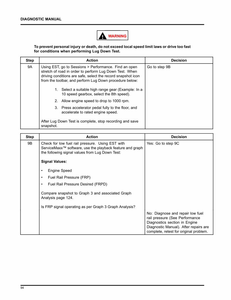
DIAGNOSTIC MANUAL
WARNING
To prevent personal injury or death, do not exceed local speed limit laws or drive too fastfor conditions when performing Lug Down Test.
Step Action Decision9A Using EST, go to Sessions > Performance. Find an open
stretch of road in order to perform Lug Down Test. Whendriving conditions are safe, select the record snapshot iconfrom the toolbar, and perform Lug Down procedure below:
1. Select a suitable high range gear (Example: In a10 speed gearbox, select the 8th speed).
2. Allow engine speed to drop to 1000 rpm.
3. Press accelerator pedal fully to the floor, andaccelerate to rated engine speed.
After Lug Down Test is complete, stop recording and savesnapshot.
Go to step 9B
Step Action Decision9B Check for low fuel rail pressure. Using EST with
ServiceMaxx™ software, use the playback feature and graphthe following signal values from Lug Down Test:
Signal Values:
• Engine Speed
• Fuel Rail Pressure (FRP)
• Fuel Rail Pressure Desired (FRPD)
Compare snapshot to Graph 3 and associated GraphAnalysis page 124.
Is FRP signal operating as per Graph 3 Graph Analysis?
Yes: Go to step 9C
No: Diagnose and repair low fuelrail pressure (See PerformanceDiagnostics section in EngineDiagnostic Manual). After repairs arecomplete, retest for original problem.
94
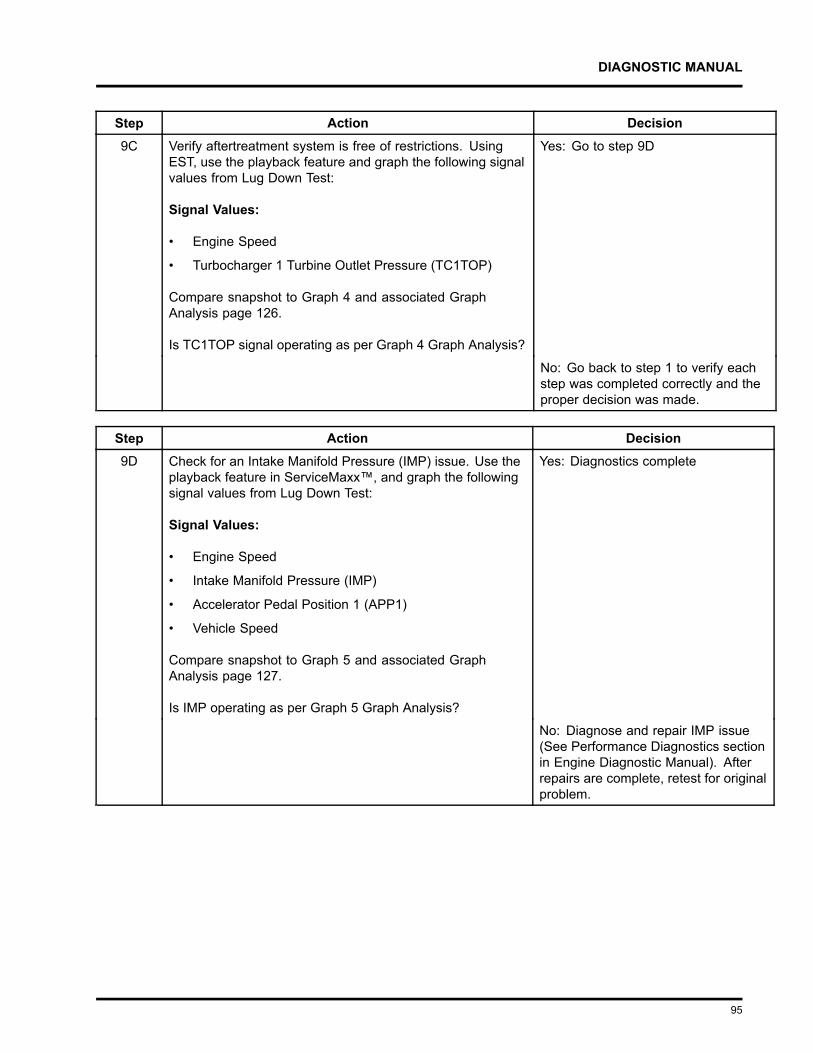
DIAGNOSTIC MANUAL
Step Action Decision9C Verify aftertreatment system is free of restrictions. Using
EST, use the playback feature and graph the following signalvalues from Lug Down Test:
Signal Values:
• Engine Speed
• Turbocharger 1 Turbine Outlet Pressure (TC1TOP)
Compare snapshot to Graph 4 and associated GraphAnalysis page 126.
Is TC1TOP signal operating as per Graph 4 Graph Analysis?
Yes: Go to step 9D
No: Go back to step 1 to verify eachstep was completed correctly and theproper decision was made.
Step Action Decision9D Check for an Intake Manifold Pressure (IMP) issue. Use the
playback feature in ServiceMaxx™, and graph the followingsignal values from Lug Down Test:
Signal Values:
• Engine Speed
• Intake Manifold Pressure (IMP)
• Accelerator Pedal Position 1 (APP1)
• Vehicle Speed
Compare snapshot to Graph 5 and associated GraphAnalysis page 127.
Is IMP operating as per Graph 5 Graph Analysis?
Yes: Diagnostics complete
No: Diagnose and repair IMP issue(See Performance Diagnostics sectionin Engine Diagnostic Manual). Afterrepairs are complete, retest for originalproblem.
95
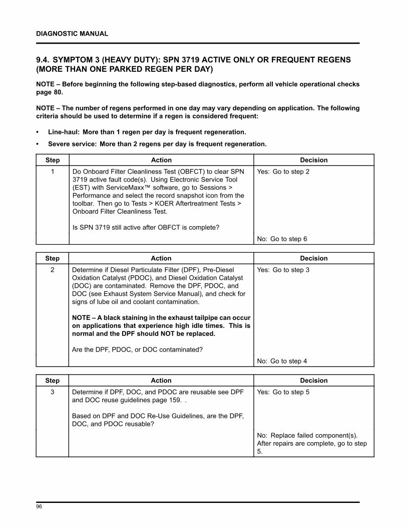
DIAGNOSTIC MANUAL
9.4. SYMPTOM 3 (HEAVY DUTY): SPN 3719 ACTIVE ONLY OR FREQUENT REGENS(MORE THAN ONE PARKED REGEN PER DAY)
NOTE – Before beginning the following step-based diagnostics, perform all vehicle operational checkspage 80.
NOTE – The number of regens performed in one day may vary depending on application. The followingcriteria should be used to determine if a regen is considered frequent:
• Line-haul: More than 1 regen per day is frequent regeneration.
• Severe service: More than 2 regens per day is frequent regeneration.
Step Action Decision1 Do Onboard Filter Cleanliness Test (OBFCT) to clear SPN
3719 active fault code(s). Using Electronic Service Tool(EST) with ServiceMaxx™ software, go to Sessions >Performance and select the record snapshot icon from thetoolbar. Then go to Tests > KOER Aftertreatment Tests >Onboard Filter Cleanliness Test.
Is SPN 3719 still active after OBFCT is complete?
Yes: Go to step 2
No: Go to step 6
Step Action Decision2 Determine if Diesel Particulate Filter (DPF), Pre-Diesel
Oxidation Catalyst (PDOC), and Diesel Oxidation Catalyst(DOC) are contaminated. Remove the DPF, PDOC, andDOC (see Exhaust System Service Manual), and check forsigns of lube oil and coolant contamination.
NOTE – A black staining in the exhaust tailpipe can occuron applications that experience high idle times. This isnormal and the DPF should NOT be replaced.
Are the DPF, PDOC, or DOC contaminated?
Yes: Go to step 3
No: Go to step 4
Step Action Decision3 Determine if DPF, DOC, and PDOC are reusable see DPF
and DOC reuse guidelines page 159. .
Based on DPF and DOC Re-Use Guidelines, are the DPF,DOC, and PDOC reusable?
Yes: Go to step 5
No: Replace failed component(s).After repairs are complete, go to step5.
96

DIAGNOSTIC MANUAL
Step Action Decision4 Determine if removed aftertreatment system components
need to be cleaned see DPF and DOC reuse guidelinespage 159.
Based on DPF and DOC Re-Use Guidelines, do any of theremoved aftertreatment system components need to becleaned?
Yes: Clean components usingappropriate cleaning equipment. Aftercleaning procedure is complete, installcomponents and go to step 6.
No: Install removed aftertreatmentsystem components, and then go tostep 6.
Step Action Decision5 Determine root cause of exhaust system contamination.
(See Engine Symptoms Diagnostics section in EngineDiagnostic Manual.)
After repairs are complete, go to step 7
Step Action Decision6 Diesel Particulate Filter (DPF) Snap Acceleration Test (Quick
Test). This procedure checks the DPF for cracks or internaldamage without removing the DPF from the vehicle and isused to test basic functionality of the DPF. This is to be doneprior to removing the DPF.
1. The transmission must be in neutral and theparking brake applied.
2. Start and idle the engine.
3. Rapidly snap the accelerator pedal from idleto full throttle. This can be performed multipletimes.
4. During the engine accelerations, visually checkfor a heavy black smoke exiting the exhaustpipe.
Is black smoke visible?
Yes: Go to symptom 5 (Heavy Duty):Black smoke page 113.
No: Go to step 7
97
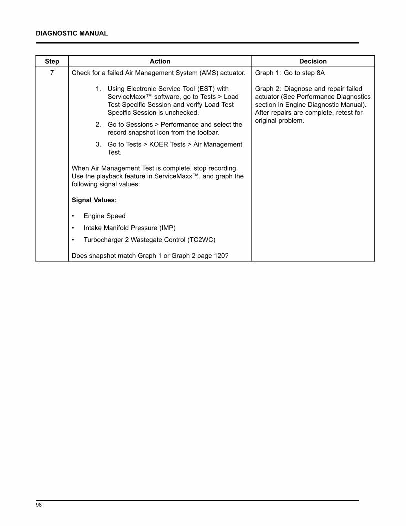
DIAGNOSTIC MANUAL
Step Action Decision7 Check for a failed Air Management System (AMS) actuator.
1. Using Electronic Service Tool (EST) withServiceMaxx™ software, go to Tests > LoadTest Specific Session and verify Load TestSpecific Session is unchecked.
2. Go to Sessions > Performance and select therecord snapshot icon from the toolbar.
3. Go to Tests > KOER Tests > Air ManagementTest.
When Air Management Test is complete, stop recording.Use the playback feature in ServiceMaxx™, and graph thefollowing signal values:
Signal Values:
• Engine Speed
• Intake Manifold Pressure (IMP)
• Turbocharger 2 Wastegate Control (TC2WC)
Does snapshot match Graph 1 or Graph 2 page 120?
Graph 1: Go to step 8A
Graph 2: Diagnose and repair failedactuator (See Performance Diagnosticssection in Engine Diagnostic Manual).After repairs are complete, retest fororiginal problem.
98
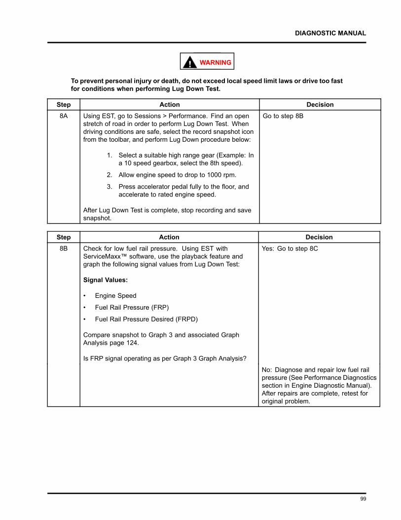
DIAGNOSTIC MANUAL
WARNING
To prevent personal injury or death, do not exceed local speed limit laws or drive too fastfor conditions when performing Lug Down Test.
Step Action Decision8A Using EST, go to Sessions > Performance. Find an open
stretch of road in order to perform Lug Down Test. Whendriving conditions are safe, select the record snapshot iconfrom the toolbar, and perform Lug Down procedure below:
1. Select a suitable high range gear (Example: Ina 10 speed gearbox, select the 8th speed).
2. Allow engine speed to drop to 1000 rpm.
3. Press accelerator pedal fully to the floor, andaccelerate to rated engine speed.
After Lug Down Test is complete, stop recording and savesnapshot.
Go to step 8B
Step Action Decision8B Check for low fuel rail pressure. Using EST with
ServiceMaxx™ software, use the playback feature andgraph the following signal values from Lug Down Test:
Signal Values:
• Engine Speed
• Fuel Rail Pressure (FRP)
• Fuel Rail Pressure Desired (FRPD)
Compare snapshot to Graph 3 and associated GraphAnalysis page 124.
Is FRP signal operating as per Graph 3 Graph Analysis?
Yes: Go to step 8C
No: Diagnose and repair low fuel railpressure (See Performance Diagnosticssection in Engine Diagnostic Manual).After repairs are complete, retest fororiginal problem.
99
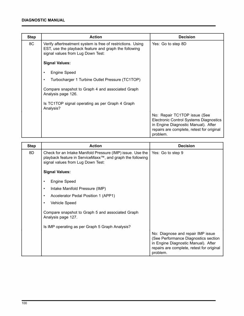
DIAGNOSTIC MANUAL
Step Action Decision8C Verify aftertreatment system is free of restrictions. Using
EST, use the playback feature and graph the followingsignal values from Lug Down Test:
Signal Values:
• Engine Speed
• Turbocharger 1 Turbine Outlet Pressure (TC1TOP)
Compare snapshot to Graph 4 and associated GraphAnalysis page 126.
Is TC1TOP signal operating as per Graph 4 GraphAnalysis?
Yes: Go to step 8D
No: Repair TC1TOP issue (SeeElectronic Control Systems Diagnosticsin Engine Diagnostic Manual). Afterrepairs are complete, retest for originalproblem.
Step Action Decision8D Check for an Intake Manifold Pressure (IMP) issue. Use the
playback feature in ServiceMaxx™, and graph the followingsignal values from Lug Down Test:
Signal Values:
• Engine Speed
• Intake Manifold Pressure (IMP)
• Accelerator Pedal Position 1 (APP1)
• Vehicle Speed
Compare snapshot to Graph 5 and associated GraphAnalysis page 127.
Is IMP operating as per Graph 5 Graph Analysis?
Yes: Go to step 9
No: Diagnose and repair IMP issue(See Performance Diagnostics sectionin Engine Diagnostic Manual). Afterrepairs are complete, retest for originalproblem.
100
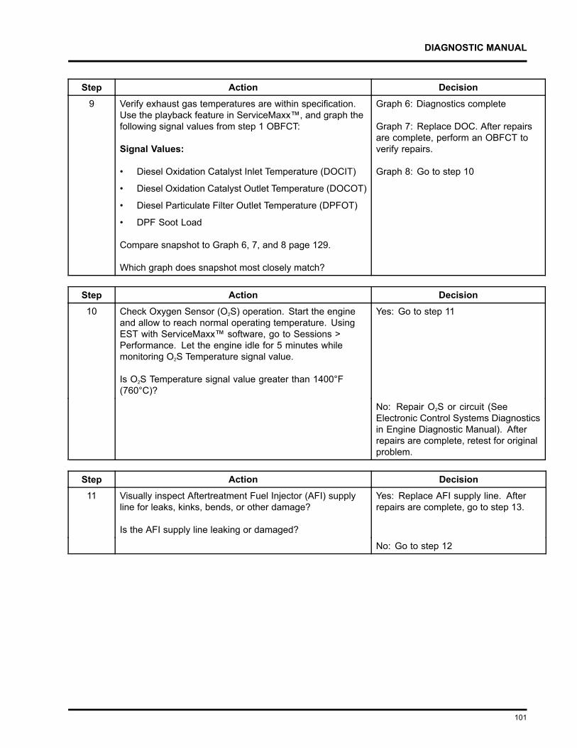
DIAGNOSTIC MANUAL
Step Action Decision9 Verify exhaust gas temperatures are within specification.
Use the playback feature in ServiceMaxx™, and graph thefollowing signal values from step 1 OBFCT:
Signal Values:
• Diesel Oxidation Catalyst Inlet Temperature (DOCIT)
• Diesel Oxidation Catalyst Outlet Temperature (DOCOT)
• Diesel Particulate Filter Outlet Temperature (DPFOT)
• DPF Soot Load
Compare snapshot to Graph 6, 7, and 8 page 129.
Which graph does snapshot most closely match?
Graph 6: Diagnostics complete
Graph 7: Replace DOC. After repairsare complete, perform an OBFCT toverify repairs.
Graph 8: Go to step 10
Step Action Decision10 Check Oxygen Sensor (O2S) operation. Start the engine
and allow to reach normal operating temperature. UsingEST with ServiceMaxx™ software, go to Sessions >Performance. Let the engine idle for 5 minutes whilemonitoring O2S Temperature signal value.
Is O2S Temperature signal value greater than 1400°F(760°C)?
Yes: Go to step 11
No: Repair O2S or circuit (SeeElectronic Control Systems Diagnosticsin Engine Diagnostic Manual). Afterrepairs are complete, retest for originalproblem.
Step Action Decision11 Visually inspect Aftertreatment Fuel Injector (AFI) supply
line for leaks, kinks, bends, or other damage?
Is the AFI supply line leaking or damaged?
Yes: Replace AFI supply line. Afterrepairs are complete, go to step 13.
No: Go to step 12
101
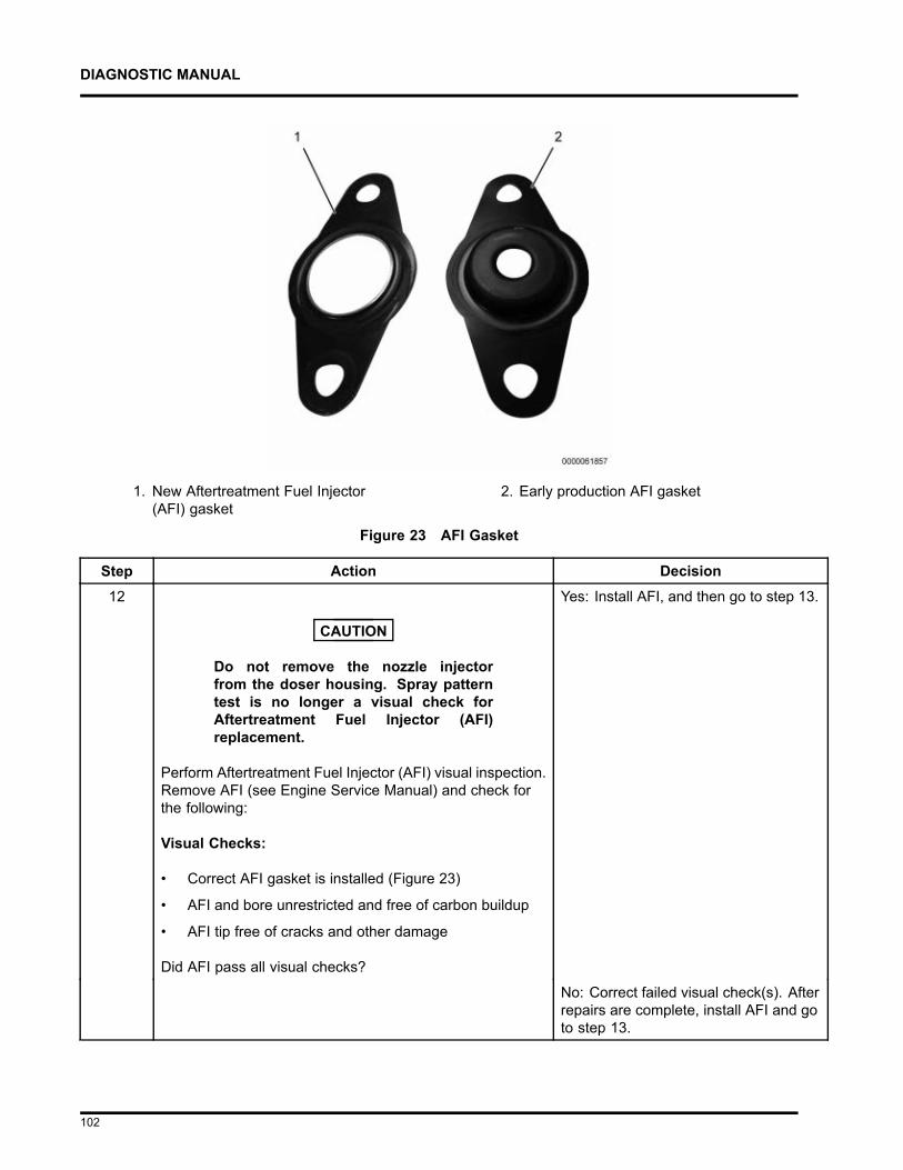
DIAGNOSTIC MANUAL
1. New Aftertreatment Fuel Injector(AFI) gasket
2. Early production AFI gasket
Figure 23 AFI Gasket
Step Action Decision12
CAUTION
Do not remove the nozzle injectorfrom the doser housing. Spray patterntest is no longer a visual check forAftertreatment Fuel Injector (AFI)replacement.
Perform Aftertreatment Fuel Injector (AFI) visual inspection.Remove AFI (see Engine Service Manual) and check forthe following:
Visual Checks:
• Correct AFI gasket is installed (Figure 23)
• AFI and bore unrestricted and free of carbon buildup
• AFI tip free of cracks and other damage
Did AFI pass all visual checks?
Yes: Install AFI, and then go to step 13.
No: Correct failed visual check(s). Afterrepairs are complete, install AFI and goto step 13.
102
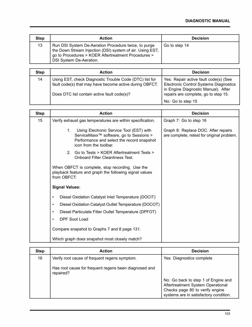
DIAGNOSTIC MANUAL
Step Action Decision13 Run DSI System De-Aeration Procedure twice, to purge
the Down Stream Injection (DSI) system of air. Using EST,go to Procedures > KOER Aftertreatment Procedures >DSI System De-Aeration.
Go to step 14
Step Action Decision14 Using EST, check Diagnostic Trouble Code (DTC) list for
fault code(s) that may have become active during OBFCT.
Does DTC list contain active fault code(s)?
Yes: Repair active fault code(s) (SeeElectronic Control Systems Diagnosticsin Engine Diagnostic Manual). Afterrepairs are complete, go to step 15.
No: Go to step 15
Step Action Decision15 Verify exhaust gas temperatures are within specification.
1. Using Electronic Service Tool (EST) withServiceMaxx™ software, go to Sessions >Performance and select the record snapshoticon from the toolbar.
2. Go to Tests > KOER Aftertreatment Tests >Onboard Filter Cleanliness Test.
When OBFCT is complete, stop recording. Use theplayback feature and graph the following signal valuesfrom OBFCT:
Signal Values:
• Diesel Oxidation Catalyst Inlet Temperature (DOCIT)
• Diesel Oxidation Catalyst Outlet Temperature (DOCOT)
• Diesel Particulate Filter Outlet Temperature (DPFOT)
• DPF Soot Load
Compare snapshot to Graphs 7 and 8 page 131.
Which graph does snapshot most closely match?
Graph 7: Go to step 16
Graph 8: Replace DOC. After repairsare complete, retest for original problem.
Step Action Decision16 Verify root cause of frequent regens symptom.
Has root cause for frequent regens been diagnosed andrepaired?
Yes: Diagnostics complete
No: Go back to step 1 of Engine andAftertreatment System OperationalChecks page 80 to verify enginesystems are in satisfactory condition.
103
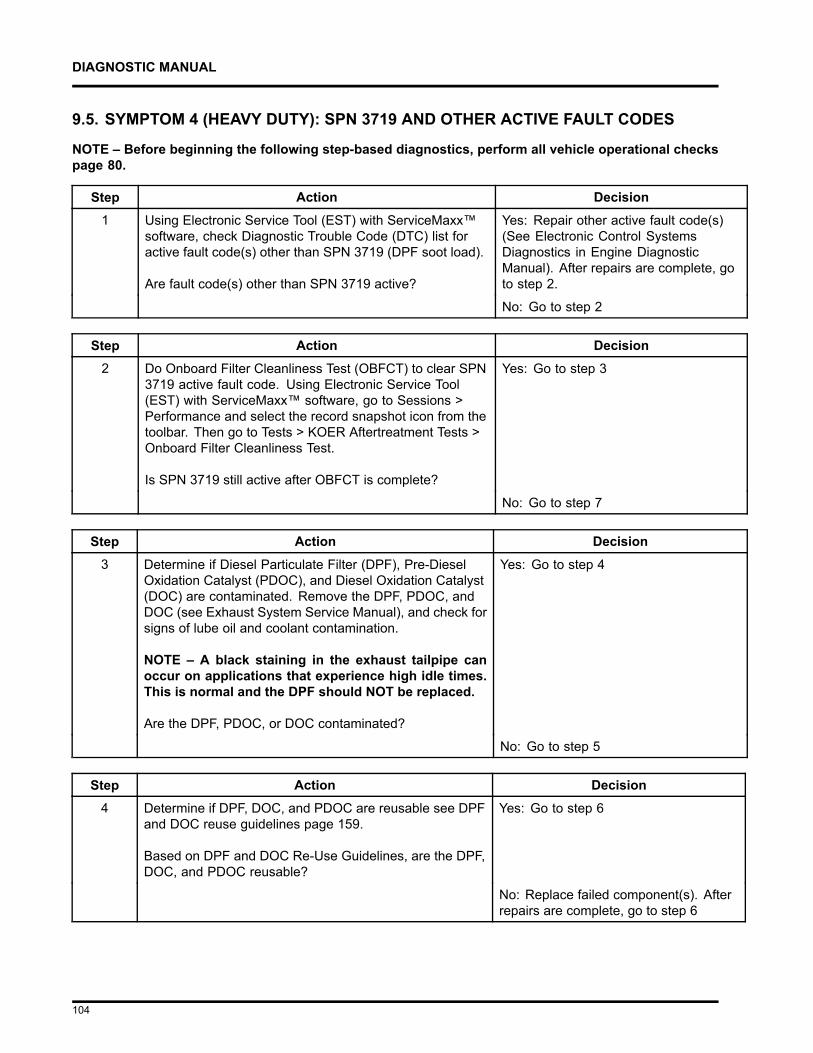
DIAGNOSTIC MANUAL
9.5. SYMPTOM 4 (HEAVY DUTY): SPN 3719 AND OTHER ACTIVE FAULT CODES
NOTE – Before beginning the following step-based diagnostics, perform all vehicle operational checkspage 80.
Step Action Decision1 Using Electronic Service Tool (EST) with ServiceMaxx™
software, check Diagnostic Trouble Code (DTC) list foractive fault code(s) other than SPN 3719 (DPF soot load).
Are fault code(s) other than SPN 3719 active?
Yes: Repair other active fault code(s)(See Electronic Control SystemsDiagnostics in Engine DiagnosticManual). After repairs are complete, goto step 2.
No: Go to step 2
Step Action Decision2 Do Onboard Filter Cleanliness Test (OBFCT) to clear SPN
3719 active fault code. Using Electronic Service Tool(EST) with ServiceMaxx™ software, go to Sessions >Performance and select the record snapshot icon from thetoolbar. Then go to Tests > KOER Aftertreatment Tests >Onboard Filter Cleanliness Test.
Is SPN 3719 still active after OBFCT is complete?
Yes: Go to step 3
No: Go to step 7
Step Action Decision3 Determine if Diesel Particulate Filter (DPF), Pre-Diesel
Oxidation Catalyst (PDOC), and Diesel Oxidation Catalyst(DOC) are contaminated. Remove the DPF, PDOC, andDOC (see Exhaust System Service Manual), and check forsigns of lube oil and coolant contamination.
NOTE – A black staining in the exhaust tailpipe canoccur on applications that experience high idle times.This is normal and the DPF should NOT be replaced.
Are the DPF, PDOC, or DOC contaminated?
Yes: Go to step 4
No: Go to step 5
Step Action Decision4 Determine if DPF, DOC, and PDOC are reusable see DPF
and DOC reuse guidelines page 159.
Based on DPF and DOC Re-Use Guidelines, are the DPF,DOC, and PDOC reusable?
Yes: Go to step 6
No: Replace failed component(s). Afterrepairs are complete, go to step 6
104
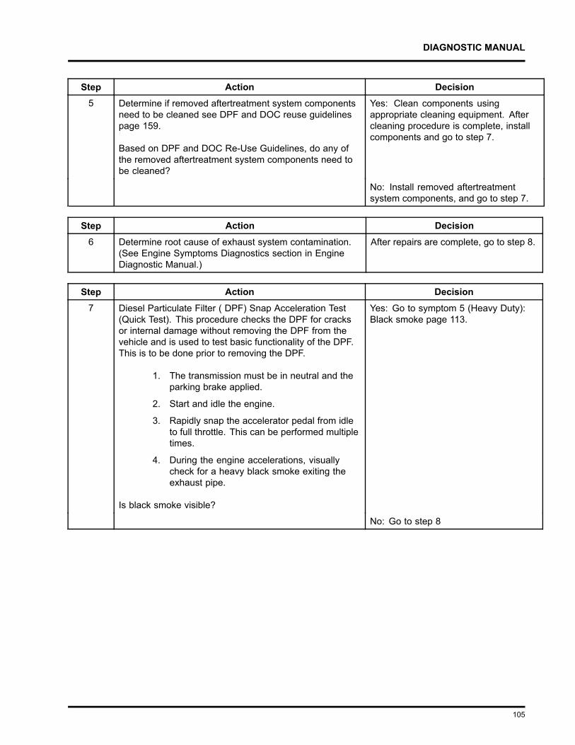
DIAGNOSTIC MANUAL
Step Action Decision5 Determine if removed aftertreatment system components
need to be cleaned see DPF and DOC reuse guidelinespage 159.
Based on DPF and DOC Re-Use Guidelines, do any ofthe removed aftertreatment system components need tobe cleaned?
Yes: Clean components usingappropriate cleaning equipment. Aftercleaning procedure is complete, installcomponents and go to step 7.
No: Install removed aftertreatmentsystem components, and go to step 7.
Step Action Decision6 Determine root cause of exhaust system contamination.
(See Engine Symptoms Diagnostics section in EngineDiagnostic Manual.)
After repairs are complete, go to step 8.
Step Action Decision7 Diesel Particulate Filter ( DPF) Snap Acceleration Test
(Quick Test). This procedure checks the DPF for cracksor internal damage without removing the DPF from thevehicle and is used to test basic functionality of the DPF.This is to be done prior to removing the DPF.
1. The transmission must be in neutral and theparking brake applied.
2. Start and idle the engine.
3. Rapidly snap the accelerator pedal from idleto full throttle. This can be performed multipletimes.
4. During the engine accelerations, visuallycheck for a heavy black smoke exiting theexhaust pipe.
Is black smoke visible?
Yes: Go to symptom 5 (Heavy Duty):Black smoke page 113.
No: Go to step 8
105

DIAGNOSTIC MANUAL
Step Action Decision8 Check for a failed Air Management System (AMS) actuator.
1. Using Electronic Service Tool (EST) withServiceMaxx™ software, go to Tests > LoadTest Specific Session and verify Load TestSpecific Session is unchecked.
2. Go to Sessions > Performance and select therecord snapshot icon from the toolbar.
3. Go to Tests > KOER Tests > Air ManagementTest.
When Air Management Test is complete, stop recording.Use the playback feature in ServiceMaxx™, and graphthe following signal values:
Signal Values:
• Engine Speed
• Intake Manifold Pressure (IMP)
• Turbocharger 2 Wastegate Control (TC2WC)
Does snapshot match Graph 1 or Graph 2 page 120?
Graph 1: Go to step 9A
Graph 2: Diagnose and repair failedactuator (See Performance Diagnosticssection in Engine Diagnostic Manual).After repairs are complete, retest fororiginal problem.
106
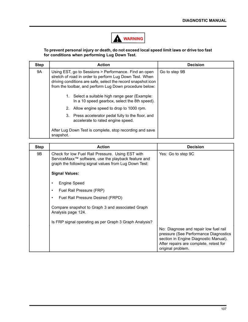
DIAGNOSTIC MANUAL
WARNING
To prevent personal injury or death, do not exceed local speed limit laws or drive too fastfor conditions when performing Lug Down Test.
Step Action Decision9A Using EST, go to Sessions > Performance. Find an open
stretch of road in order to perform Lug Down Test. Whendriving conditions are safe, select the record snapshot iconfrom the toolbar, and perform Lug Down procedure below:
1. Select a suitable high range gear (Example:In a 10 speed gearbox, select the 8th speed).
2. Allow engine speed to drop to 1000 rpm.
3. Press accelerator pedal fully to the floor, andaccelerate to rated engine speed.
After Lug Down Test is complete, stop recording and savesnapshot.
Go to step 9B
Step Action Decision9B Check for low Fuel Rail Pressure. Using EST with
ServiceMaxx™ software, use the playback feature andgraph the following signal values from Lug Down Test:
Signal Values:
• Engine Speed
• Fuel Rail Pressure (FRP)
• Fuel Rail Pressure Desired (FRPD)
Compare snapshot to Graph 3 and associated GraphAnalysis page 124.
Is FRP signal operating as per Graph 3 Graph Analysis?
Yes: Go to step 9C
No: Diagnose and repair low fuel railpressure (See Performance Diagnosticssection in Engine Diagnostic Manual).After repairs are complete, retest fororiginal problem.
107
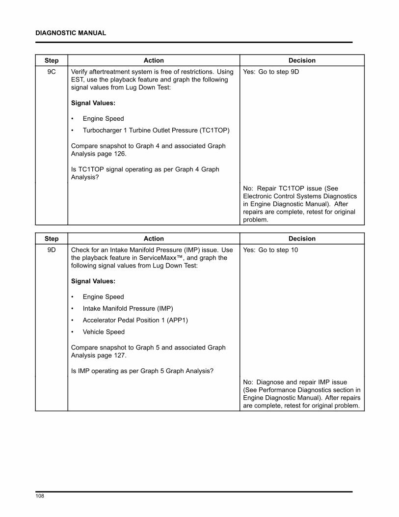
DIAGNOSTIC MANUAL
Step Action Decision9C Verify aftertreatment system is free of restrictions. Using
EST, use the playback feature and graph the followingsignal values from Lug Down Test:
Signal Values:
• Engine Speed
• Turbocharger 1 Turbine Outlet Pressure (TC1TOP)
Compare snapshot to Graph 4 and associated GraphAnalysis page 126.
Is TC1TOP signal operating as per Graph 4 GraphAnalysis?
Yes: Go to step 9D
No: Repair TC1TOP issue (SeeElectronic Control Systems Diagnosticsin Engine Diagnostic Manual). Afterrepairs are complete, retest for originalproblem.
Step Action Decision9D Check for an Intake Manifold Pressure (IMP) issue. Use
the playback feature in ServiceMaxx™, and graph thefollowing signal values from Lug Down Test:
Signal Values:
• Engine Speed
• Intake Manifold Pressure (IMP)
• Accelerator Pedal Position 1 (APP1)
• Vehicle Speed
Compare snapshot to Graph 5 and associated GraphAnalysis page 127.
Is IMP operating as per Graph 5 Graph Analysis?
Yes: Go to step 10
No: Diagnose and repair IMP issue(See Performance Diagnostics section inEngine Diagnostic Manual). After repairsare complete, retest for original problem.
108
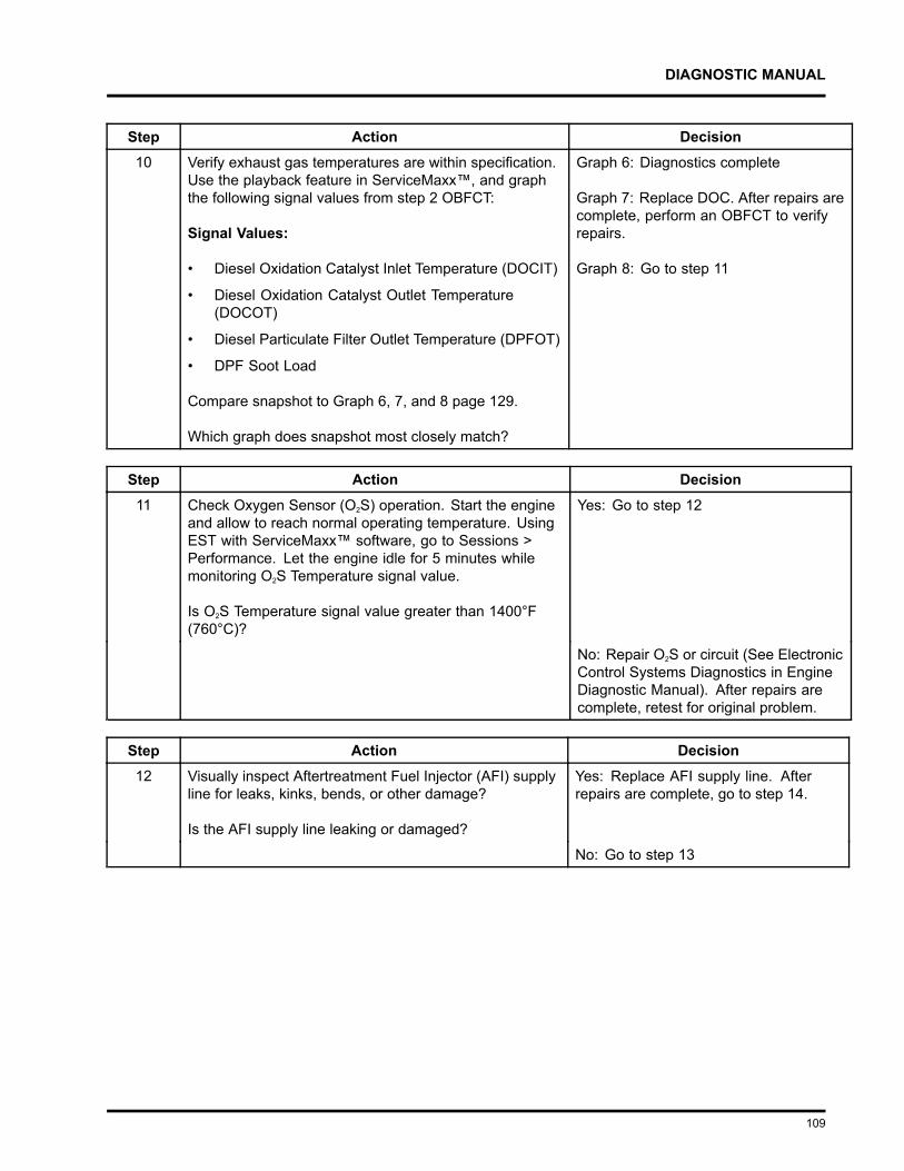
DIAGNOSTIC MANUAL
Step Action Decision10 Verify exhaust gas temperatures are within specification.
Use the playback feature in ServiceMaxx™, and graphthe following signal values from step 2 OBFCT:
Signal Values:
• Diesel Oxidation Catalyst Inlet Temperature (DOCIT)
• Diesel Oxidation Catalyst Outlet Temperature(DOCOT)
• Diesel Particulate Filter Outlet Temperature (DPFOT)
• DPF Soot Load
Compare snapshot to Graph 6, 7, and 8 page 129.
Which graph does snapshot most closely match?
Graph 6: Diagnostics complete
Graph 7: Replace DOC. After repairs arecomplete, perform an OBFCT to verifyrepairs.
Graph 8: Go to step 11
Step Action Decision11 Check Oxygen Sensor (O2S) operation. Start the engine
and allow to reach normal operating temperature. UsingEST with ServiceMaxx™ software, go to Sessions >Performance. Let the engine idle for 5 minutes whilemonitoring O2S Temperature signal value.
Is O2S Temperature signal value greater than 1400°F(760°C)?
Yes: Go to step 12
No: Repair O2S or circuit (See ElectronicControl Systems Diagnostics in EngineDiagnostic Manual). After repairs arecomplete, retest for original problem.
Step Action Decision12 Visually inspect Aftertreatment Fuel Injector (AFI) supply
line for leaks, kinks, bends, or other damage?
Is the AFI supply line leaking or damaged?
Yes: Replace AFI supply line. Afterrepairs are complete, go to step 14.
No: Go to step 13
109
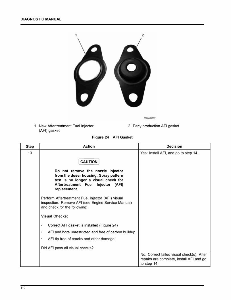
DIAGNOSTIC MANUAL
1. New Aftertreatment Fuel Injector(AFI) gasket
2. Early production AFI gasket
Figure 24 AFI Gasket
Step Action Decision13
CAUTION
Do not remove the nozzle injectorfrom the doser housing. Spray patterntest is no longer a visual check forAftertreatment Fuel Injector (AFI)replacement.
Perform Aftertreatment Fuel Injector (AFI) visualinspection. Remove AFI (see Engine Service Manual)and check for the following:
Visual Checks:
• Correct AFI gasket is installed (Figure 24)
• AFI and bore unrestricted and free of carbon buildup
• AFI tip free of cracks and other damage
Did AFI pass all visual checks?
Yes: Install AFI, and go to step 14.
No: Correct failed visual check(s). Afterrepairs are complete, install AFI and goto step 14.
110
DIAGNOSTIC MANUAL
Step Action Decision14 Run DSI System De-Aeration Procedure twice, to
purge the Down Stream Injection (DSI) system of air.Using EST, go to Procedures > KOER AftertreatmentProcedures > DSI System De-Aeration.
After procedure is complete, go to step15.
Step Action Decision15 Using EST, check Diagnostic Trouble Code (DTC) list for
fault code(s) that may have become active during OBFCT.
Does DTC list contain active fault code(s)?
Yes: Repair active fault code(s) (SeeElectronic Control Systems Diagnosticsin Engine Diagnostic Manual). Afterrepairs are complete, go to step 16.
No: Go to step 16
Step Action Decision16 Verify exhaust gas temperatures are within specification.
1. Using Electronic Service Tool (EST) withServiceMaxx™ software, go to Sessions >Performance and select the record snapshoticon from the toolbar.
2. Go to Tests > KOER Aftertreatment Tests >Onboard Filter Cleanliness Test.
When OBFCT is complete, stop recording. Use theplayback feature and graph the following signal valuesfrom OBFCT:
Signal Values:
• Diesel Oxidation Catalyst Inlet Temperature (DOCIT)
• Diesel Oxidation Catalyst Outlet Temperature(DOCOT)
• Diesel Particulate Filter Outlet Temperature (DPFOT)
• DPF Soot Load
Compare snapshot to Graphs 7 and 8 page 131.
Which graph does snapshot most closely match?
Graph 7: Go to step 17
Graph 8: Replace DOC. After repairs arecomplete, retest for original problem.
111
DIAGNOSTIC MANUAL
Step Action Decision17 Verify root cause of frequent regens symptom.
Has root cause for frequent regens been diagnosed andrepaired?
Yes: Diagnostics complete
No: Go back to step 1 of Engine andAftertreatment System OperationalChecks page 80 to verify engine systemsare in satisfactory condition.
112
DIAGNOSTIC MANUAL
9.6. SYMPTOM 5 (HEAVY DUTY): BLACK SMOKE
OVERVIEW: Hydrocarbon slip occurs when diesel fuel does not fully combust in the aftertreatmentsystem and slips through the DPF into the clean side of the exhaust. Hydrocarbon slip is associatedwith high idle time. The DPF should NOT be replaced due to black staining in the exhaust.
NOTE – The Diesel Particulate Filter (DPF) is not 100 percent efficient. Some evidence of exhaust sootis normal, and does not indicate a malfunctioning DPF.
WARNING
To prevent unexpected movement of the vehicle and possible injury or death, park thevehicle on a flat, level surface, apply the parking brake, turn the engine off and chock thewheels to prevent vehicle from moving in either direction.
NOTE – Before beginning the following step-based diagnostics, perform all vehicle operational checkspage 80.
Step Action Decision1 Diesel Particulate Filter ( DPF) Snap Acceleration Test
(Quick Test). This procedure checks the DPF for cracksor internal damage without removing the DPF from thevehicle and is used to test basic functionality of the DPF.This is to be done prior to removing the DPF.
1. The transmission must be in neutral and theparking brake applied.
2. Start and idle the engine.
3. Rapidly snap the accelerator pedal fromidle to full throttle. This can be performedmultiple times.
4. During the engine accelerations, visuallycheck for a heavy black smoke exiting theexhaust pipe.
Is black smoke visible?
Yes: Go to step 2
End of diagnostics
113
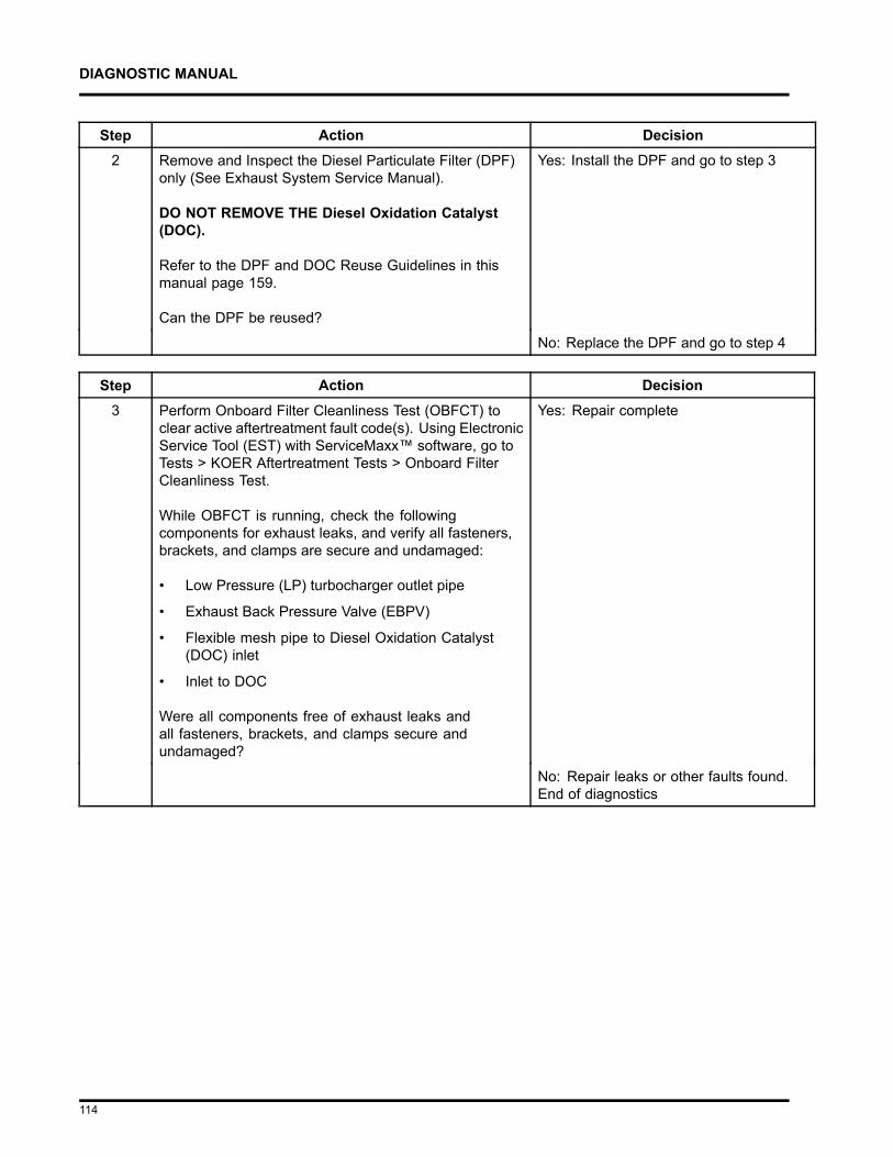
DIAGNOSTIC MANUAL
Step Action Decision2 Remove and Inspect the Diesel Particulate Filter (DPF)
only (See Exhaust System Service Manual).
DO NOT REMOVE THE Diesel Oxidation Catalyst(DOC).
Refer to the DPF and DOC Reuse Guidelines in thismanual page 159.
Can the DPF be reused?
Yes: Install the DPF and go to step 3
No: Replace the DPF and go to step 4
Step Action Decision3 Perform Onboard Filter Cleanliness Test (OBFCT) to
clear active aftertreatment fault code(s). Using ElectronicService Tool (EST) with ServiceMaxx™ software, go toTests > KOER Aftertreatment Tests > Onboard FilterCleanliness Test.
While OBFCT is running, check the followingcomponents for exhaust leaks, and verify all fasteners,brackets, and clamps are secure and undamaged:
• Low Pressure (LP) turbocharger outlet pipe
• Exhaust Back Pressure Valve (EBPV)
• Flexible mesh pipe to Diesel Oxidation Catalyst(DOC) inlet
• Inlet to DOC
Were all components free of exhaust leaks andall fasteners, brackets, and clamps secure andundamaged?
Yes: Repair complete
No: Repair leaks or other faults found.End of diagnostics
114
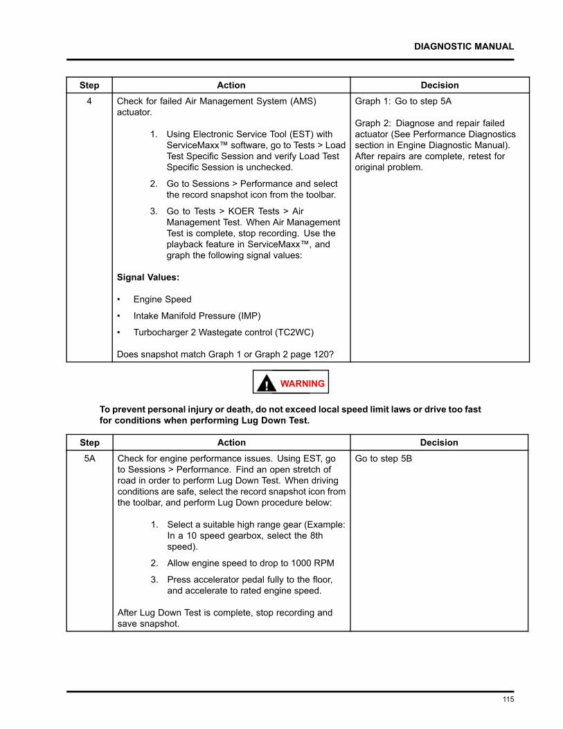
DIAGNOSTIC MANUAL
Step Action Decision4 Check for failed Air Management System (AMS)
actuator.
1. Using Electronic Service Tool (EST) withServiceMaxx™ software, go to Tests > LoadTest Specific Session and verify Load TestSpecific Session is unchecked.
2. Go to Sessions > Performance and selectthe record snapshot icon from the toolbar.
3. Go to Tests > KOER Tests > AirManagement Test. When Air ManagementTest is complete, stop recording. Use theplayback feature in ServiceMaxx™, andgraph the following signal values:
Signal Values:
• Engine Speed
• Intake Manifold Pressure (IMP)
• Turbocharger 2 Wastegate control (TC2WC)
Does snapshot match Graph 1 or Graph 2 page 120?
Graph 1: Go to step 5A
Graph 2: Diagnose and repair failedactuator (See Performance Diagnosticssection in Engine Diagnostic Manual).After repairs are complete, retest fororiginal problem.
WARNING
To prevent personal injury or death, do not exceed local speed limit laws or drive too fastfor conditions when performing Lug Down Test.
Step Action Decision5A Check for engine performance issues. Using EST, go
to Sessions > Performance. Find an open stretch ofroad in order to perform Lug Down Test. When drivingconditions are safe, select the record snapshot icon fromthe toolbar, and perform Lug Down procedure below:
1. Select a suitable high range gear (Example:In a 10 speed gearbox, select the 8thspeed).
2. Allow engine speed to drop to 1000 RPM
3. Press accelerator pedal fully to the floor,and accelerate to rated engine speed.
After Lug Down Test is complete, stop recording andsave snapshot.
Go to step 5B
115
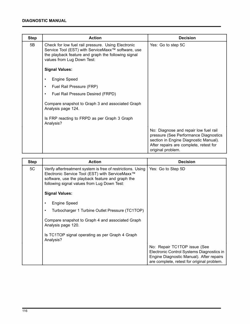
DIAGNOSTIC MANUAL
Step Action Decision5B Check for low fuel rail pressure. Using Electronic
Service Tool (EST) with ServiceMaxx™ software, usethe playback feature and graph the following signalvalues from Lug Down Test:
Signal Values:
• Engine Speed
• Fuel Rail Pressure (FRP)
• Fuel Rail Pressure Desired (FRPD)
Compare snapshot to Graph 3 and associated GraphAnalysis page 124.
Is FRP reacting to FRPD as per Graph 3 GraphAnalysis?
Yes: Go to step 5C
No: Diagnose and repair low fuel railpressure (See Performance Diagnosticssection in Engine Diagnostic Manual).After repairs are complete, retest fororiginal problem.
Step Action Decision5C Verify aftertreatment system is free of restrictions. Using
Electronic Service Tool (EST) with ServiceMaxx™software, use the playback feature and graph thefollowing signal values from Lug Down Test:
Signal Values:
• Engine Speed
• Turbocharger 1 Turbine Outlet Pressure (TC1TOP)
Compare snapshot to Graph 4 and associated GraphAnalysis page 120.
Is TC1TOP signal operating as per Graph 4 GraphAnalysis?
Yes: Go to Step 5D
No: Repair TC1TOP issue (SeeElectronic Control Systems Diagnostics inEngine Diagnostic Manual). After repairsare complete, retest for original problem.
116
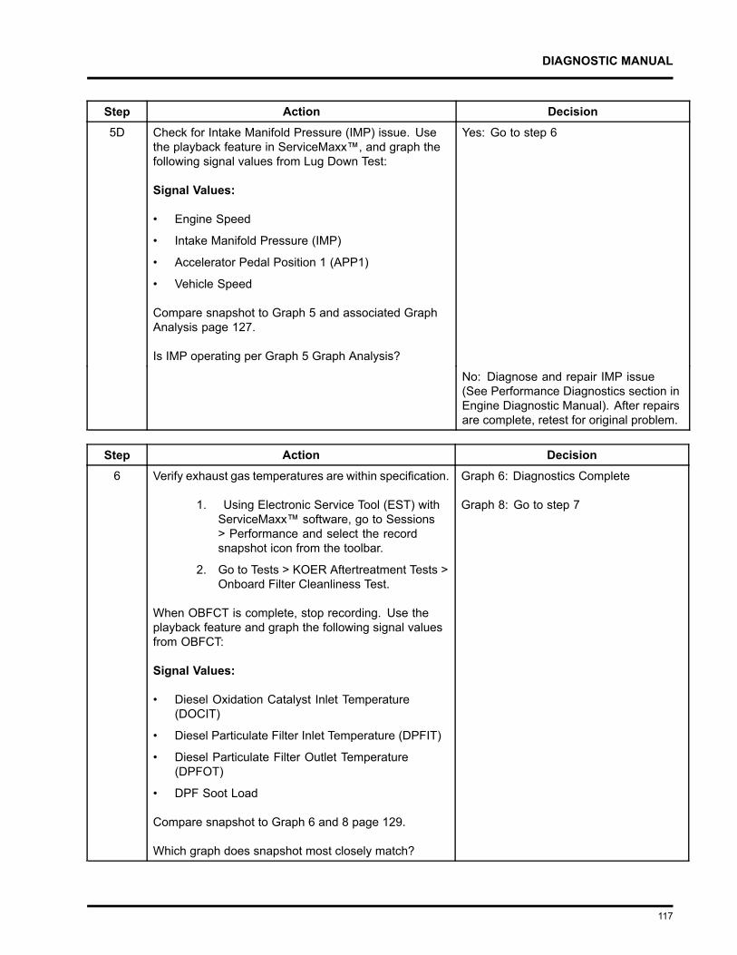
DIAGNOSTIC MANUAL
Step Action Decision5D Check for Intake Manifold Pressure (IMP) issue. Use
the playback feature in ServiceMaxx™, and graph thefollowing signal values from Lug Down Test:
Signal Values:
• Engine Speed
• Intake Manifold Pressure (IMP)
• Accelerator Pedal Position 1 (APP1)
• Vehicle Speed
Compare snapshot to Graph 5 and associated GraphAnalysis page 127.
Is IMP operating per Graph 5 Graph Analysis?
Yes: Go to step 6
No: Diagnose and repair IMP issue(See Performance Diagnostics section inEngine Diagnostic Manual). After repairsare complete, retest for original problem.
Step Action Decision6 Verify exhaust gas temperatures are within specification.
1. Using Electronic Service Tool (EST) withServiceMaxx™ software, go to Sessions> Performance and select the recordsnapshot icon from the toolbar.
2. Go to Tests > KOER Aftertreatment Tests >Onboard Filter Cleanliness Test.
When OBFCT is complete, stop recording. Use theplayback feature and graph the following signal valuesfrom OBFCT:
Signal Values:
• Diesel Oxidation Catalyst Inlet Temperature(DOCIT)
• Diesel Particulate Filter Inlet Temperature (DPFIT)
• Diesel Particulate Filter Outlet Temperature(DPFOT)
• DPF Soot Load
Compare snapshot to Graph 6 and 8 page 129.
Which graph does snapshot most closely match?
Graph 6: Diagnostics Complete
Graph 8: Go to step 7
117
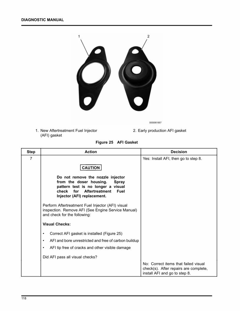
DIAGNOSTIC MANUAL
1. New Aftertreatment Fuel Injector(AFI) gasket
2. Early production AFI gasket
Figure 25 AFI Gasket
Step Action Decision7
CAUTION
Do not remove the nozzle injectorfrom the doser housing. Spraypattern test is no longer a visualcheck for Aftertreatment FuelInjector (AFI) replacement.
Perform Aftertreatment Fuel Injector (AFI) visualinspection. Remove AFI (See Engine Service Manual)and check for the following:
Visual Checks:
• Correct AFI gasket is installed (Figure 25)
• AFI and bore unrestricted and free of carbon buildup
• AFI tip free of cracks and other visible damage
Did AFI pass all visual checks?
Yes: Install AFI, then go to step 8.
No: Correct items that failed visualcheck(s). After repairs are complete,install AFI and go to step 8.
118
DIAGNOSTIC MANUAL
Step Action Decision8 Run Down Stream Injection (DSI) System De-Aeration
Procedure twice, to purge the DSI system of air. UsingElectronic Service Tool (EST) with ServiceMaxx™software, go to Procedures > KOER AftertreatmentProcedures > DSI System De-Aeration.
Go to step 9
Step Action Decision9 Using Electronic Service Tool (EST) with ServiceMaxx™
software, check Diagnostic Trouble Code (DTC) list forany fault code(s) that may have become active duringOBFCT.
Does DTC list contain any active fault code(s)?
Yes: Repair active fault code(s) (SeeElectronic Control Systems Diagnostics inEngine Diagnostic Manual). After repairsare complete, go to step 10
No: Go to step 10
Step Action Decision10 Verify exhaust gas temperatures are within specification.
1. Using Electronic Service Tool (EST) withServiceMaxx™ software, go to Tests >KOER Aftertreatment Tests > OnboardFilter Cleanliness Test (OBFCT).
2. Go to Sessions > Performance and selectthe record snapshot icon from the toolbar.
When OBFCT is complete, stop recording. Use theplayback feature and graph the following signal valuesfrom OBFCT:
Signal Values
Signal Values:
• Diesel Oxidation Catalyst Inlet Temperature(DOCIT)
• Diesel Particulate Filter Inlet Temperature (DPFIT)
• Diesel Particulate Filter Outlet Temperature(DPFOT)
• DPF Soot Load
Compare snapshot to Graphs 6 and 8 page 129.
Which graph does snapshot most closely match?
Graph 6: Repair complete
Graph 8: Go to Performance Diagnosticsin the Engine Service Manual. Afterrepairs are complete, retest for originalproblem.
119
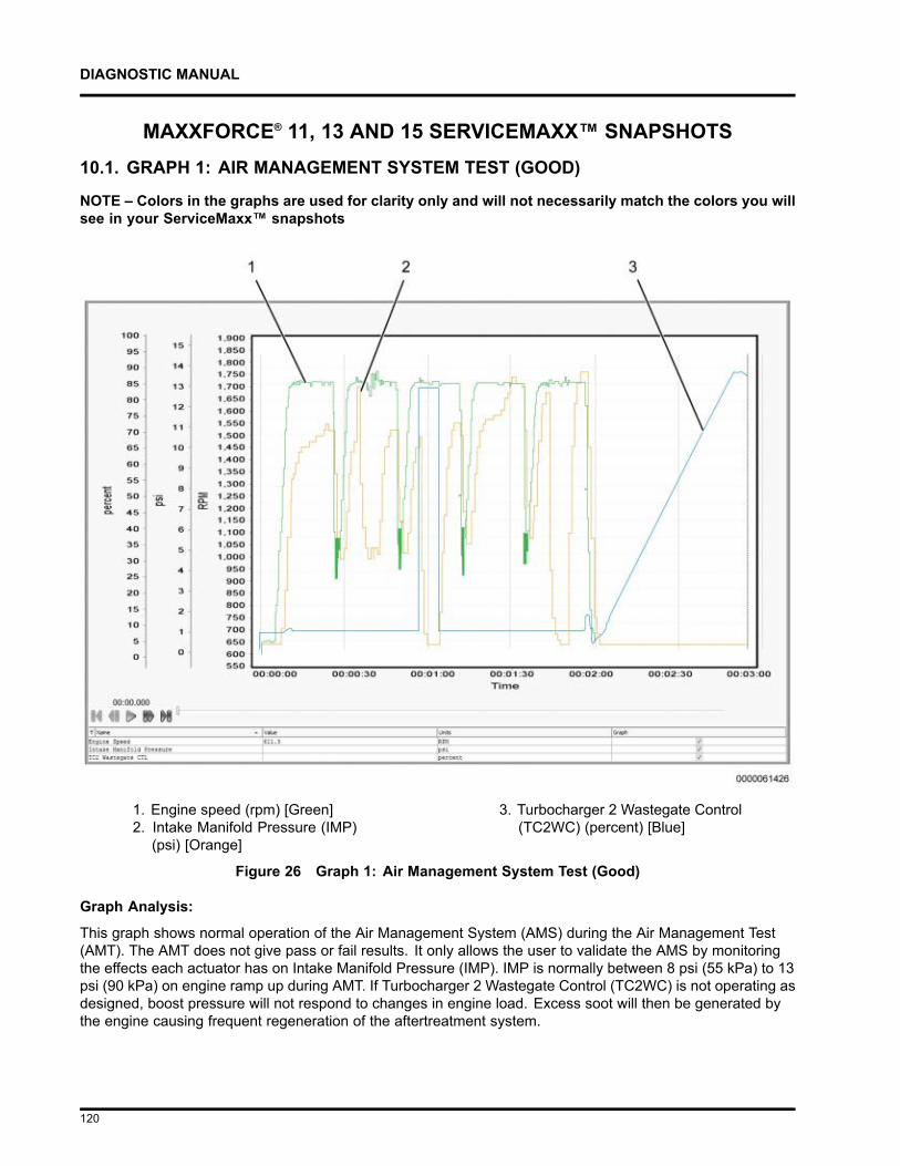
DIAGNOSTIC MANUAL
MAXXFORCE® 11, 13 AND 15 SERVICEMAXX™ SNAPSHOTS10.1. GRAPH 1: AIR MANAGEMENT SYSTEM TEST (GOOD)
NOTE – Colors in the graphs are used for clarity only and will not necessarily match the colors you willsee in your ServiceMaxx™ snapshots
1. Engine speed (rpm) [Green]2. Intake Manifold Pressure (IMP)
(psi) [Orange]
3. Turbocharger 2 Wastegate Control(TC2WC) (percent) [Blue]
Figure 26 Graph 1: Air Management System Test (Good)
Graph Analysis:
This graph shows normal operation of the Air Management System (AMS) during the Air Management Test(AMT). The AMT does not give pass or fail results. It only allows the user to validate the AMS by monitoringthe effects each actuator has on Intake Manifold Pressure (IMP). IMP is normally between 8 psi (55 kPa) to 13psi (90 kPa) on engine ramp up during AMT. If Turbocharger 2 Wastegate Control (TC2WC) is not operating asdesigned, boost pressure will not respond to changes in engine load. Excess soot will then be generated bythe engine causing frequent regeneration of the aftertreatment system.
120
DIAGNOSTIC MANUAL
Actions:
1. When TC2WC is commanded ON, verify Intake Manifold Pressure (IMP) signal value drops.
NOTE – MaxxForce® 11 ONLY: AFT regen status stays “Not Active.”
NOTE – Turbocharger 1 Wastegate Control (TC1WC) does not affect engine performance and is removedfrom post-production engines. If engine is equipped with one, it is not used by the Engine ControlModule (ECM).
121
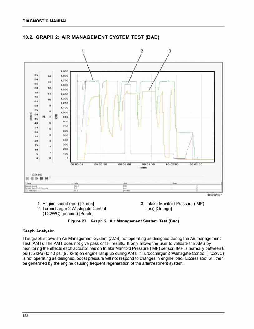
DIAGNOSTIC MANUAL
10.2. GRAPH 2: AIR MANAGEMENT SYSTEM TEST (BAD)
1. Engine speed (rpm) [Green]2. Turbocharger 2 Wastegate Control
(TC2WC) (percent) [Purple]
3. Intake Manifold Pressure (IMP)(psi) [Orange]
Figure 27 Graph 2: Air Management System Test (Bad)
Graph Analysis:
This graph shows an Air Management System (AMS) not operating as designed during the Air managementTest (AMT). The AMT does not give pass or fail results. It only allows the user to validate the AMS bymonitoring the effects each actuator has on Intake Manifold Pressure (IMP) sensor. IMP is normally between 8psi (55 kPa) to 13 psi (90 kPa) on engine ramp up during AMT. If Turbocharger 2 Wastegate Control (TC2WC)is not operating as designed, boost pressure will not respond to changes in engine load. Excess soot will thenbe generated by the engine causing frequent regeneration of the aftertreatment system.
122
DIAGNOSTIC MANUAL
Actions:
1. When Turbocharger 2 Wastegate Control (TC2WC) is commanded ON, verify Intake ManifoldPressure (IMP) drops. In this graph, IMP does not drop when TC2WC is commanded ON.
NOTE – MaxxForce® 11 ONLY: AFT regen status stays “Not Active.”
NOTE – Turbocharger 1 Wastegate Control (TC1WC) does not affect engine performance and is removedfrom post-production engines. If engine is equipped with one, it is not used by the Engine ControlModule (ECM).
123
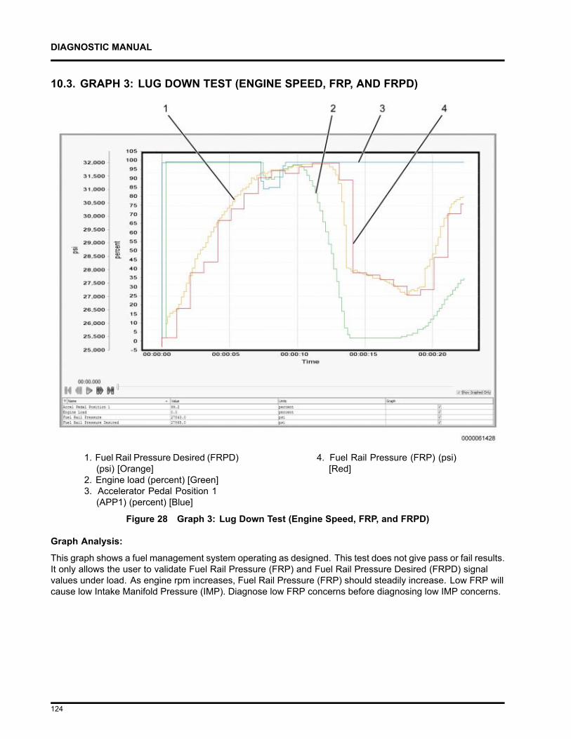
DIAGNOSTIC MANUAL
10.3. GRAPH 3: LUG DOWN TEST (ENGINE SPEED, FRP, AND FRPD)
1. Fuel Rail Pressure Desired (FRPD)(psi) [Orange]
2. Engine load (percent) [Green]3. Accelerator Pedal Position 1
(APP1) (percent) [Blue]
4. Fuel Rail Pressure (FRP) (psi)[Red]
Figure 28 Graph 3: Lug Down Test (Engine Speed, FRP, and FRPD)
Graph Analysis:
This graph shows a fuel management system operating as designed. This test does not give pass or fail results.It only allows the user to validate Fuel Rail Pressure (FRP) and Fuel Rail Pressure Desired (FRPD) signalvalues under load. As engine rpm increases, Fuel Rail Pressure (FRP) should steadily increase. Low FRP willcause low Intake Manifold Pressure (IMP). Diagnose low FRP concerns before diagnosing low IMP concerns.
124
DIAGNOSTIC MANUAL
Actions:
1. Verify FRP signal value reaches 31,900 psi (219,943 kPa) at full load.
2. Verify FRP signal value is within a 1000 psi (6,895 kPa) range of FRPD signal value duringacceleration.
NOTE – Analyze Lug Down Test signal values only during engine acceleration, and not deceleration orshifting.
125
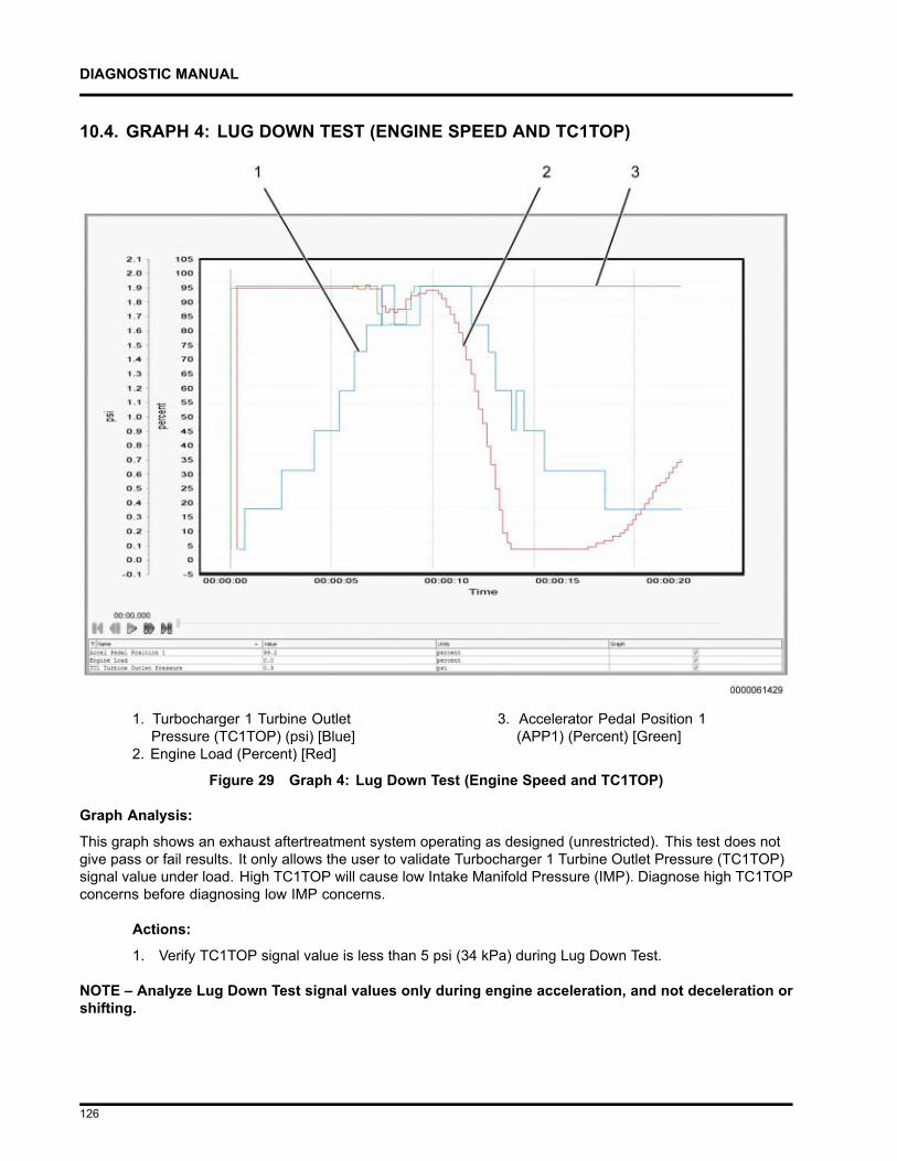
DIAGNOSTIC MANUAL
10.4. GRAPH 4: LUG DOWN TEST (ENGINE SPEED AND TC1TOP)
1. Turbocharger 1 Turbine OutletPressure (TC1TOP) (psi) [Blue]
2. Engine Load (Percent) [Red]
3. Accelerator Pedal Position 1(APP1) (Percent) [Green]
Figure 29 Graph 4: Lug Down Test (Engine Speed and TC1TOP)
Graph Analysis:
This graph shows an exhaust aftertreatment system operating as designed (unrestricted). This test does notgive pass or fail results. It only allows the user to validate Turbocharger 1 Turbine Outlet Pressure (TC1TOP)signal value under load. High TC1TOP will cause low Intake Manifold Pressure (IMP). Diagnose high TC1TOPconcerns before diagnosing low IMP concerns.
Actions:
1. Verify TC1TOP signal value is less than 5 psi (34 kPa) during Lug Down Test.
NOTE – Analyze Lug Down Test signal values only during engine acceleration, and not deceleration orshifting.
126
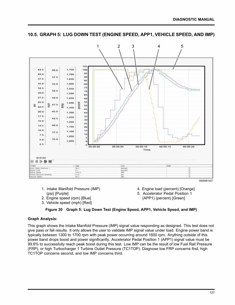
DIAGNOSTIC MANUAL
10.5. GRAPH 5: LUG DOWN TEST (ENGINE SPEED, APP1, VEHICLE SPEED, AND IMP)
1. Intake Manifold Pressure (IMP)(psi) [Purple]
2. Engine speed (rpm) [Blue]3. Vehicle speed (mph) [Red]
4. Engine load (percent) [Orange]5. Accelerator Pedal Position 1
(APP1) (percent) [Green]
Figure 30 Graph 5: Lug Down Test (Engine Speed, APP1, Vehicle Speed, and IMP)
Graph Analysis:
This graph shows the Intake Manifold Pressure (IMP) signal value responding as designed. This test does notgive pass or fail results. It only allows the user to validate IMP signal value under load. Engine power band istypically between 1300 to 1700 rpm with peak power occurring around 1600 rpm. Anything outside of thispower band drops boost and power significantly. Accelerator Pedal Position 1 (APP1) signal value must be99.6% to successfully reach peak boost during this test. Low IMP can be the result of low Fuel Rail Pressure(FRP), or high Turbocharger 1 Turbine Outlet Pressure (TC1TOP). Diagnose low FRP concerns first, highTC1TOP concerns second, and low IMP concerns third.
127
DIAGNOSTIC MANUAL
1. Verify IMP signal value is between 40 psi (276 kPa) to 43 psi (296 kPa), with Accelerator PedalPosition 1 (APP1) signal value at 99.6%, and engine speed between 1300 rpm to 1700 rpm.
NOTE – Analyze Lug Down Test signal values only during engine acceleration, and not deceleration orshifting.
128
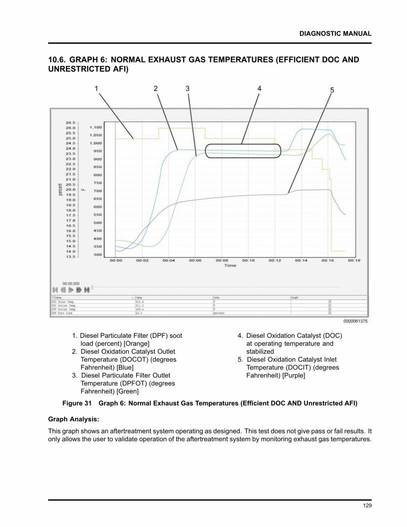
DIAGNOSTIC MANUAL
10.6. GRAPH 6: NORMAL EXHAUST GAS TEMPERATURES (EFFICIENT DOC ANDUNRESTRICTED AFI)
1. Diesel Particulate Filter (DPF) sootload (percent) [Orange]
2. Diesel Oxidation Catalyst OutletTemperature (DOCOT) (degreesFahrenheit) [Blue]
3. Diesel Particulate Filter OutletTemperature (DPFOT) (degreesFahrenheit) [Green]
4. Diesel Oxidation Catalyst (DOC)at operating temperature andstabilized
5. Diesel Oxidation Catalyst InletTemperature (DOCIT) (degreesFahrenheit) [Purple]
Figure 31 Graph 6: Normal Exhaust Gas Temperatures (Efficient DOC AND Unrestricted AFI)
Graph Analysis:
This graph shows an aftertreatment system operating as designed. This test does not give pass or fail results. Itonly allows the user to validate operation of the aftertreatment system by monitoring exhaust gas temperatures.
129
DIAGNOSTIC MANUAL
Actions:
1. After Diesel Oxidation Catalyst (DOC) reaches operating temperature and stabilizes (see callout 4,graph 6), verify Diesel Oxidation Catalyst Outlet Temperature (DOCOT) and Diesel ParticulateFilter Outlet Temperature (DPFOT) signal values are greater than 900°F (482°C).
2. Verify Diesel Oxidation Catalyst Inlet Temperature (DOCIT) signal value is between 550°F (287°C)to 800°F (427°C).
NOTE – It is normal to see Diesel Oxidation Catalyst Inlet Temperature (DOCIT), DOCOT, and DPFOTsignal values to fluctuate at the beginning and end of the OBFCT.
130
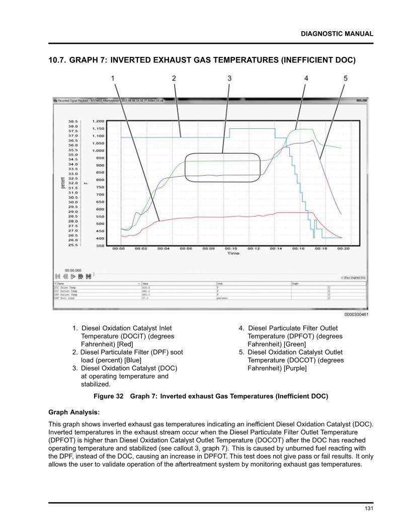
DIAGNOSTIC MANUAL
10.7. GRAPH 7: INVERTED EXHAUST GAS TEMPERATURES (INEFFICIENT DOC)
1. Diesel Oxidation Catalyst InletTemperature (DOCIT) (degreesFahrenheit) [Red]
2. Diesel Particulate Filter (DPF) sootload (percent) [Blue]
3. Diesel Oxidation Catalyst (DOC)at operating temperature andstabilized.
4. Diesel Particulate Filter OutletTemperature (DPFOT) (degreesFahrenheit) [Green]
5. Diesel Oxidation Catalyst OutletTemperature (DOCOT) (degreesFahrenheit) [Purple]
Figure 32 Graph 7: Inverted exhaust Gas Temperatures (Inefficient DOC)
Graph Analysis:
This graph shows inverted exhaust gas temperatures indicating an inefficient Diesel Oxidation Catalyst (DOC).Inverted temperatures in the exhaust stream occur when the Diesel Particulate Filter Outlet Temperature(DPFOT) is higher than Diesel Oxidation Catalyst Outlet Temperature (DOCOT) after the DOC has reachedoperating temperature and stabilized (see callout 3, graph 7). This is caused by unburned fuel reacting withthe DPF, instead of the DOC, causing an increase in DPFOT. This test does not give pass or fail results. It onlyallows the user to validate operation of the aftertreatment system by monitoring exhaust gas temperatures.
131
DIAGNOSTIC MANUAL
Actions:
1. After DOC reaches operating temperature and stabilizes (see callout 3, graph 7), verify DPFOTsignal value is not 122°F (50°C) higher than DOCOT signal value. In this graph, DPFOT signalvalue is 122°F (50°C) higher than DOCOT indicating inverted exhaust gas temperatures.
2. Verify Diesel Oxidation Catalyst Inlet Temperature (DOCIT) signal value is between 550°F (287°C)to 800°F (427°C).
NOTE – It is normal to see Diesel Oxidation Catalyst Inlet Temperature DOCIT, DOCOT, and DPFOT signalvalues to fluctuate at the beginning and end of the OBFCT.
NOTE – SPN 4766 FMI 10 (DOC Efficiency) may be active when exhaust gas temperatures are inverted.
132
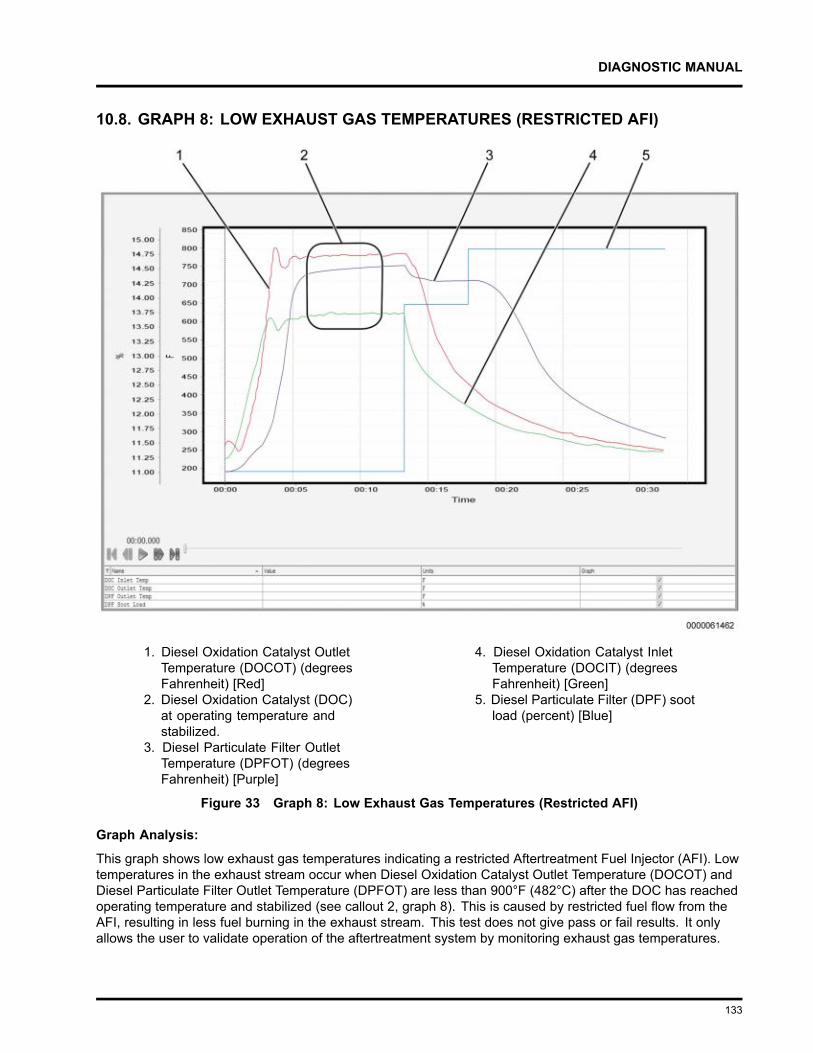
DIAGNOSTIC MANUAL
10.8. GRAPH 8: LOW EXHAUST GAS TEMPERATURES (RESTRICTED AFI)
1. Diesel Oxidation Catalyst OutletTemperature (DOCOT) (degreesFahrenheit) [Red]
2. Diesel Oxidation Catalyst (DOC)at operating temperature andstabilized.
3. Diesel Particulate Filter OutletTemperature (DPFOT) (degreesFahrenheit) [Purple]
4. Diesel Oxidation Catalyst InletTemperature (DOCIT) (degreesFahrenheit) [Green]
5. Diesel Particulate Filter (DPF) sootload (percent) [Blue]
Figure 33 Graph 8: Low Exhaust Gas Temperatures (Restricted AFI)
Graph Analysis:
This graph shows low exhaust gas temperatures indicating a restricted Aftertreatment Fuel Injector (AFI). Lowtemperatures in the exhaust stream occur when Diesel Oxidation Catalyst Outlet Temperature (DOCOT) andDiesel Particulate Filter Outlet Temperature (DPFOT) are less than 900°F (482°C) after the DOC has reachedoperating temperature and stabilized (see callout 2, graph 8). This is caused by restricted fuel flow from theAFI, resulting in less fuel burning in the exhaust stream. This test does not give pass or fail results. It onlyallows the user to validate operation of the aftertreatment system by monitoring exhaust gas temperatures.
133
DIAGNOSTIC MANUAL
Actions:
1. After DOC reaches operating temperature and stabilizes (see callout 2, graph 8), verify DOCOTand DPFOT signal values are greater than 900°F (482°C). In this graph, DOCOT and DPFOTare less than 900°F (482°C).
2. Verify Diesel Oxidation Catalyst Inlet Temperature (DOCIT) signal value is between 550°F (287°C)to 800°F (427°C).
NOTE – It is normal to see Diesel Oxidation Catalyst Inlet Temperature DOCIT, DOCOT, and DPFOT signalvalues to fluctuate at the beginning and end of the OBFCT.
134
DIAGNOSTIC MANUAL
AFTERTREATMENT SYSTEM OPERATION11.1. MAXXFORCE® 11, 13 AND 15
The Aftertreatment (AFT) system, part of the larger exhaust system, processes engine exhaust to meetemission requirements. The AFT system traps particulate matter (soot) and prevents it from leaving the tailpipe.
The AFT system performs the following functions:
• Monitors exhaust gas temperatures Diesel Oxidation Catalyst Inlet Temperature (DOCIT), Diesel OxidationCatalyst Outlet Temperature (DOCOT), and Diesel Particulate Filter Outlet Temperature (DPFOT).
• Monitors Diesel Particulate Filter Differential Pressure (DPFDP).
• Controls engine operating parameters for emission control and failure recognition.
• Cancels regeneration of the AFT system in the event of catalyst or sensor failure.
• Calculates the level of ash accumulation in the Diesel Particulate Filter (DPF).
• Initiates regeneration of the AFT system when DPF soot load is too high by increasing exhaust gastemperatures.
• Maintains vehicle and engine performance during regeneration.
135
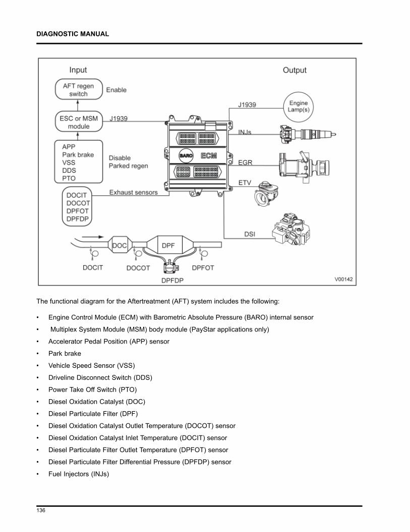
DIAGNOSTIC MANUAL
The functional diagram for the Aftertreatment (AFT) system includes the following:
• Engine Control Module (ECM) with Barometric Absolute Pressure (BARO) internal sensor
• Multiplex System Module (MSM) body module (PayStar applications only)
• Accelerator Pedal Position (APP) sensor
• Park brake
• Vehicle Speed Sensor (VSS)
• Driveline Disconnect Switch (DDS)
• Power Take Off Switch (PTO)
• Diesel Oxidation Catalyst (DOC)
• Diesel Particulate Filter (DPF)
• Diesel Oxidation Catalyst Outlet Temperature (DOCOT) sensor
• Diesel Oxidation Catalyst Inlet Temperature (DOCIT) sensor
• Diesel Particulate Filter Outlet Temperature (DPFOT) sensor
• Diesel Particulate Filter Differential Pressure (DPFDP) sensor
• Fuel Injectors (INJs)
136

DIAGNOSTIC MANUAL
• Exhaust Gas Recirculation (EGR) valve
• Engine Throttle Valve (ETV)
• Warning Indicators
• Inlet Air Heater (IAH)
• Aftertreatment Fuel Inlet Sensor (AFTFIS)
• Aftertreatment Fuel Pressure 2 (AFTFP2) sensor
• Aftertreatment Fuel Shutoff Valve (AFTFSV)
• Aftertreatment Fuel Doser (AFTFD)
• Downstream Injection (DSI) unit
137
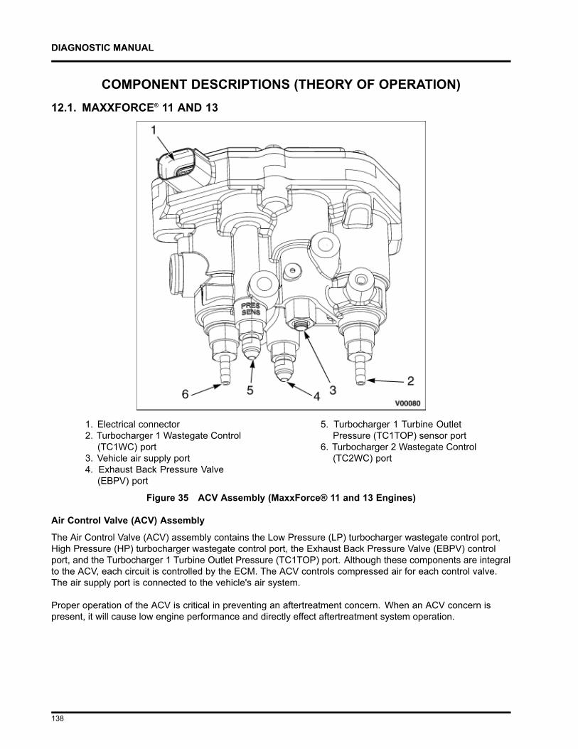
DIAGNOSTIC MANUAL
COMPONENT DESCRIPTIONS (THEORY OF OPERATION)12.1. MAXXFORCE® 11 AND 13
1. Electrical connector2. Turbocharger 1 Wastegate Control
(TC1WC) port3. Vehicle air supply port4. Exhaust Back Pressure Valve
(EBPV) port
5. Turbocharger 1 Turbine OutletPressure (TC1TOP) sensor port
6. Turbocharger 2 Wastegate Control(TC2WC) port
Figure 35 ACV Assembly (MaxxForce® 11 and 13 Engines)
Air Control Valve (ACV) Assembly
The Air Control Valve (ACV) assembly contains the Low Pressure (LP) turbocharger wastegate control port,High Pressure (HP) turbocharger wastegate control port, the Exhaust Back Pressure Valve (EBPV) controlport, and the Turbocharger 1 Turbine Outlet Pressure (TC1TOP) port. Although these components are integralto the ACV, each circuit is controlled by the ECM. The ACV controls compressed air for each control valve.The air supply port is connected to the vehicle's air system.
Proper operation of the ACV is critical in preventing an aftertreatment concern. When an ACV concern ispresent, it will cause low engine performance and directly effect aftertreatment system operation.
138
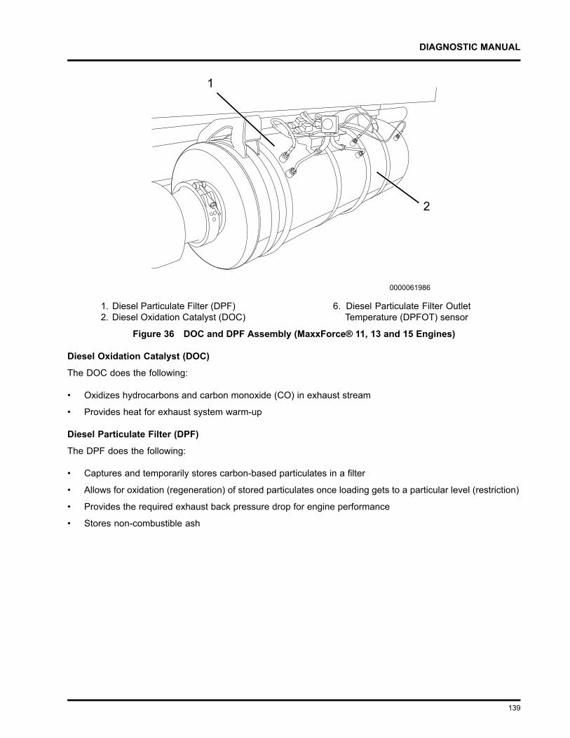
DIAGNOSTIC MANUAL
1. Diesel Particulate Filter (DPF)2. Diesel Oxidation Catalyst (DOC)
6. Diesel Particulate Filter OutletTemperature (DPFOT) sensor
Figure 36 DOC and DPF Assembly (MaxxForce® 11, 13 and 15 Engines)
Diesel Oxidation Catalyst (DOC)
The DOC does the following:
• Oxidizes hydrocarbons and carbon monoxide (CO) in exhaust stream
• Provides heat for exhaust system warm-up
Diesel Particulate Filter (DPF)
The DPF does the following:
• Captures and temporarily stores carbon-based particulates in a filter
• Allows for oxidation (regeneration) of stored particulates once loading gets to a particular level (restriction)
• Provides the required exhaust back pressure drop for engine performance
• Stores non-combustible ash
139
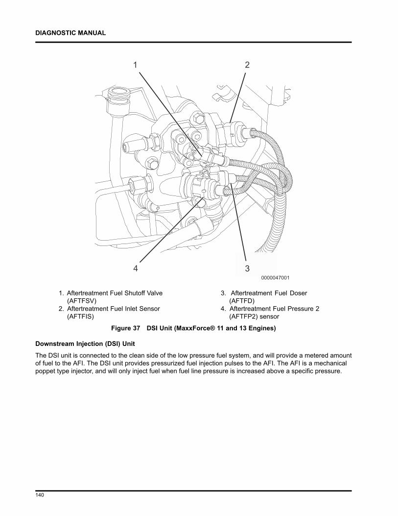
DIAGNOSTIC MANUAL
1. Aftertreatment Fuel Shutoff Valve(AFTFSV)
2. Aftertreatment Fuel Inlet Sensor(AFTFIS)
3. Aftertreatment Fuel Doser(AFTFD)
4. Aftertreatment Fuel Pressure 2(AFTFP2) sensor
Figure 37 DSI Unit (MaxxForce® 11 and 13 Engines)
Downstream Injection (DSI) Unit
The DSI unit is connected to the clean side of the low pressure fuel system, and will provide a metered amountof fuel to the AFI. The DSI unit provides pressurized fuel injection pulses to the AFI. The AFI is a mechanicalpoppet type injector, and will only inject fuel when fuel line pressure is increased above a specific pressure.
140
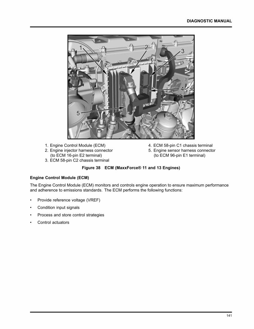
DIAGNOSTIC MANUAL
1. Engine Control Module (ECM)2. Engine injector harness connector
(to ECM 16-pin E2 terminal)3. ECM 58-pin C2 chassis terminal
4. ECM 58-pin C1 chassis terminal5. Engine sensor harness connector
(to ECM 96-pin E1 terminal)
Figure 38 ECM (MaxxForce® 11 and 13 Engines)
Engine Control Module (ECM)
The Engine Control Module (ECM) monitors and controls engine operation to ensure maximum performanceand adherence to emissions standards. The ECM performs the following functions:
• Provide reference voltage (VREF)
• Condition input signals
• Process and store control strategies
• Control actuators
141
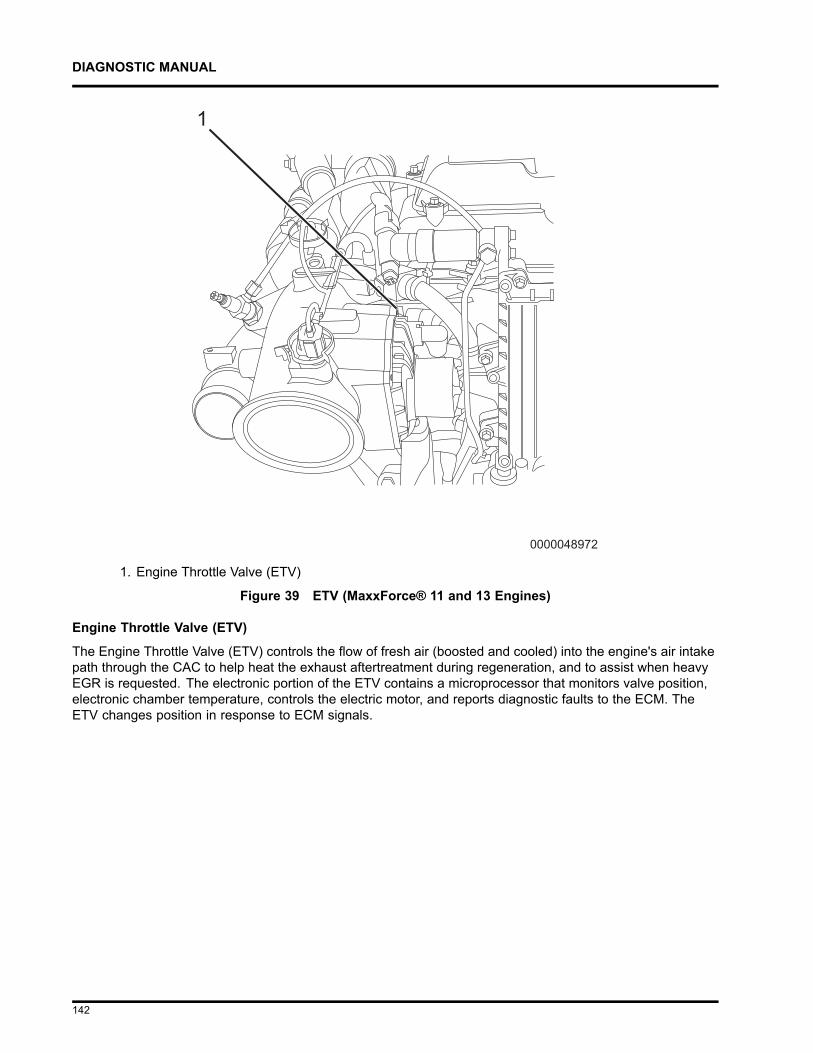
DIAGNOSTIC MANUAL
1. Engine Throttle Valve (ETV)
Figure 39 ETV (MaxxForce® 11 and 13 Engines)
Engine Throttle Valve (ETV)
The Engine Throttle Valve (ETV) controls the flow of fresh air (boosted and cooled) into the engine's air intakepath through the CAC to help heat the exhaust aftertreatment during regeneration, and to assist when heavyEGR is requested. The electronic portion of the ETV contains a microprocessor that monitors valve position,electronic chamber temperature, controls the electric motor, and reports diagnostic faults to the ECM. TheETV changes position in response to ECM signals.
142
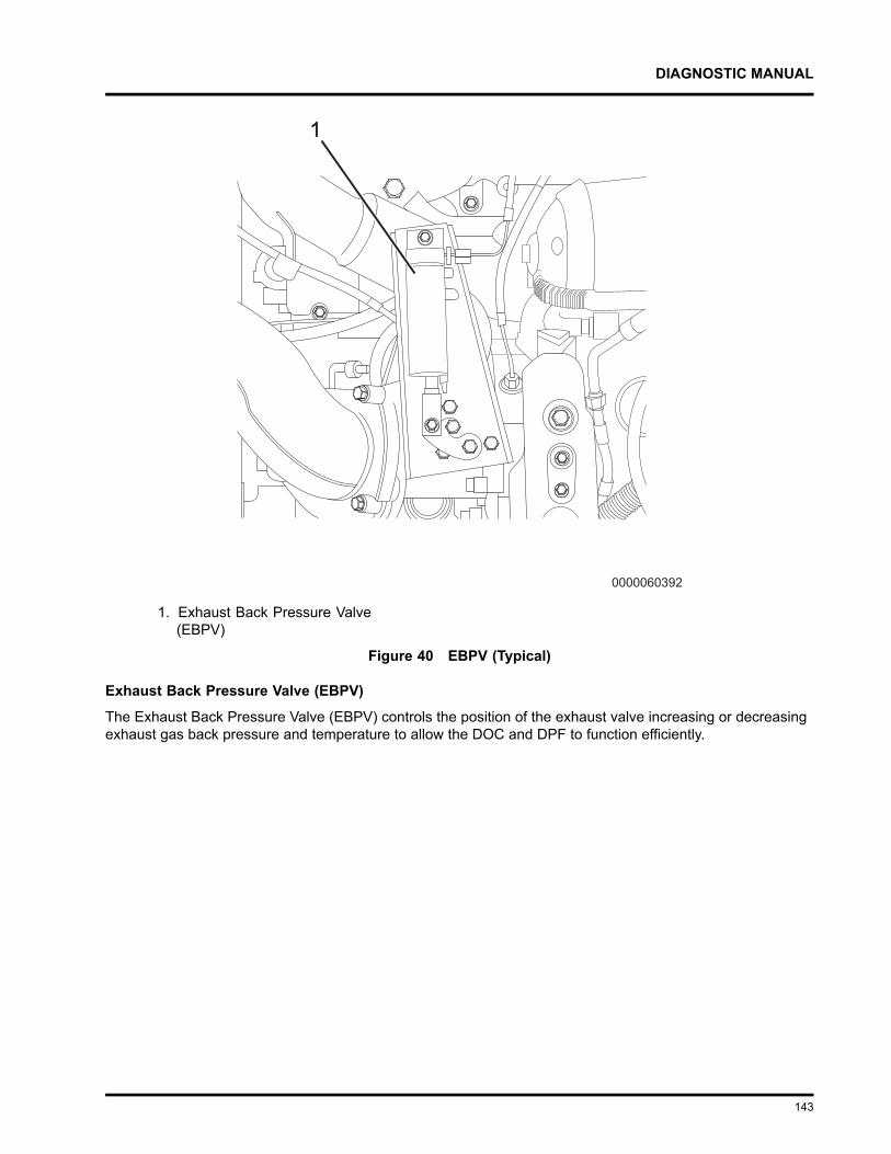
DIAGNOSTIC MANUAL
1. Exhaust Back Pressure Valve(EBPV)
Figure 40 EBPV (Typical)
Exhaust Back Pressure Valve (EBPV)
The Exhaust Back Pressure Valve (EBPV) controls the position of the exhaust valve increasing or decreasingexhaust gas back pressure and temperature to allow the DOC and DPF to function efficiently.
143
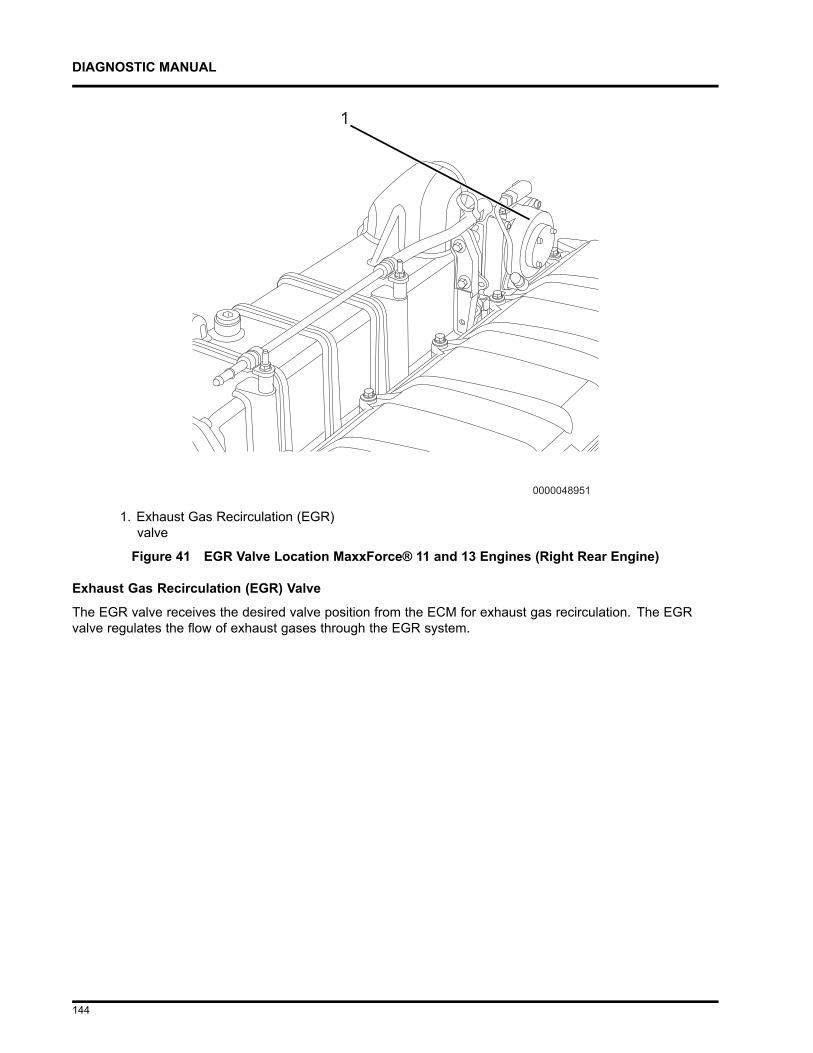
DIAGNOSTIC MANUAL
1. Exhaust Gas Recirculation (EGR)valve
Figure 41 EGR Valve Location MaxxForce® 11 and 13 Engines (Right Rear Engine)
Exhaust Gas Recirculation (EGR) Valve
The EGR valve receives the desired valve position from the ECM for exhaust gas recirculation. The EGRvalve regulates the flow of exhaust gases through the EGR system.
144
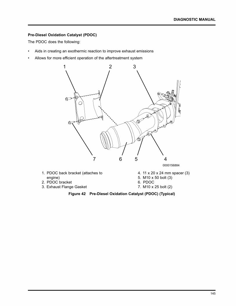
DIAGNOSTIC MANUAL
Pre-Diesel Oxidation Catalyst (PDOC)
The PDOC does the following:
• Aids in creating an exothermic reaction to improve exhaust emissions
• Allows for more efficient operation of the aftertreatment system
1. PDOC back bracket (attaches toengine)
2. PDOC bracket3. Exhaust Flange Gasket
4. 11 x 20 x 24 mm spacer (3)5. M10 x 50 bolt (3)6. PDOC7. M10 x 25 bolt (2)
Figure 42 Pre-Diesel Oxidation Catalyst (PDOC) (Typical)
145
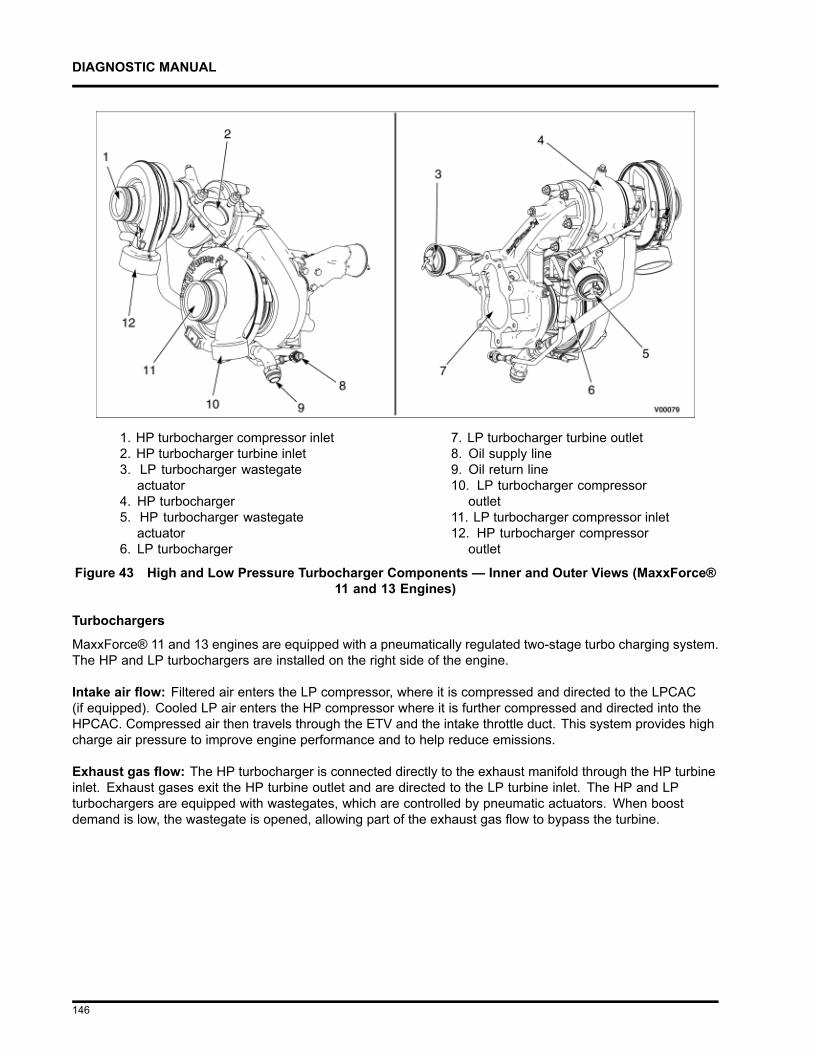
DIAGNOSTIC MANUAL
1. HP turbocharger compressor inlet2. HP turbocharger turbine inlet3. LP turbocharger wastegate
actuator4. HP turbocharger5. HP turbocharger wastegate
actuator6. LP turbocharger
7. LP turbocharger turbine outlet8. Oil supply line9. Oil return line10. LP turbocharger compressor
outlet11. LP turbocharger compressor inlet12. HP turbocharger compressor
outlet
Figure 43 High and Low Pressure Turbocharger Components — Inner and Outer Views (MaxxForce®11 and 13 Engines)
Turbochargers
MaxxForce® 11 and 13 engines are equipped with a pneumatically regulated two-stage turbo charging system.The HP and LP turbochargers are installed on the right side of the engine.
Intake air flow: Filtered air enters the LP compressor, where it is compressed and directed to the LPCAC(if equipped). Cooled LP air enters the HP compressor where it is further compressed and directed into theHPCAC. Compressed air then travels through the ETV and the intake throttle duct. This system provides highcharge air pressure to improve engine performance and to help reduce emissions.
Exhaust gas flow: The HP turbocharger is connected directly to the exhaust manifold through the HP turbineinlet. Exhaust gases exit the HP turbine outlet and are directed to the LP turbine inlet. The HP and LPturbochargers are equipped with wastegates, which are controlled by pneumatic actuators. When boostdemand is low, the wastegate is opened, allowing part of the exhaust gas flow to bypass the turbine.
146
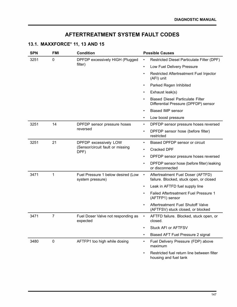
DIAGNOSTIC MANUAL
AFTERTREATMENT SYSTEM FAULT CODES13.1. MAXXFORCE® 11, 13 AND 15
SPN FMI Condition Possible Causes3251 0 DPFDP excessively HIGH (Plugged
filter)• Restricted Diesel Particulate Filter (DPF)
• Low Fuel Delivery Pressure
• Restricted Aftertreatment Fuel Injector(AFI) unit
• Parked Regen Inhibited
• Exhaust leak(s)
• Biased Diesel Particulate FilterDifferential Pressure (DPFDP) sensor
• Biased IMP sensor
• Low boost pressure
3251 14 DPFDP sensor pressure hosesreversed
• DPFDP sensor pressure hoses reversed
• DPFDP sensor hose (before filter)restricted
3251 21 DPFDP excessively LOW(Sensor/circuit fault or missingDPF)
• Biased DPFDP sensor or circuit
• Cracked DPF
• DPFDP sensor pressure hoses reversed
• DPFDP sensor hose (before filter) leakingor disconnected
3471 1 Fuel Pressure 1 below desired (Lowsystem pressure)
• Aftertreatment Fuel Doser (AFTFD)failure. Blocked, stuck open, or closed
• Leak in AFTFD fuel supply line
• Failed Aftertreatment Fuel Pressure 1(AFTFP1) sensor
• Aftertreatment Fuel Shutoff Valve(AFTFSV) stuck closed, or blocked
3471 7 Fuel Doser Valve not responding asexpected
• AFTFD failure. Blocked, stuck open, orclosed.
• Stuck AFI or AFTFSV
• Biased AFT Fuel Pressure 2 signal
3480 0 AFTFP1 too high while dosing • Fuel Delivery Pressure (FDP) abovemaximum
• Restricted fuel return line between filterhousing and fuel tank
147
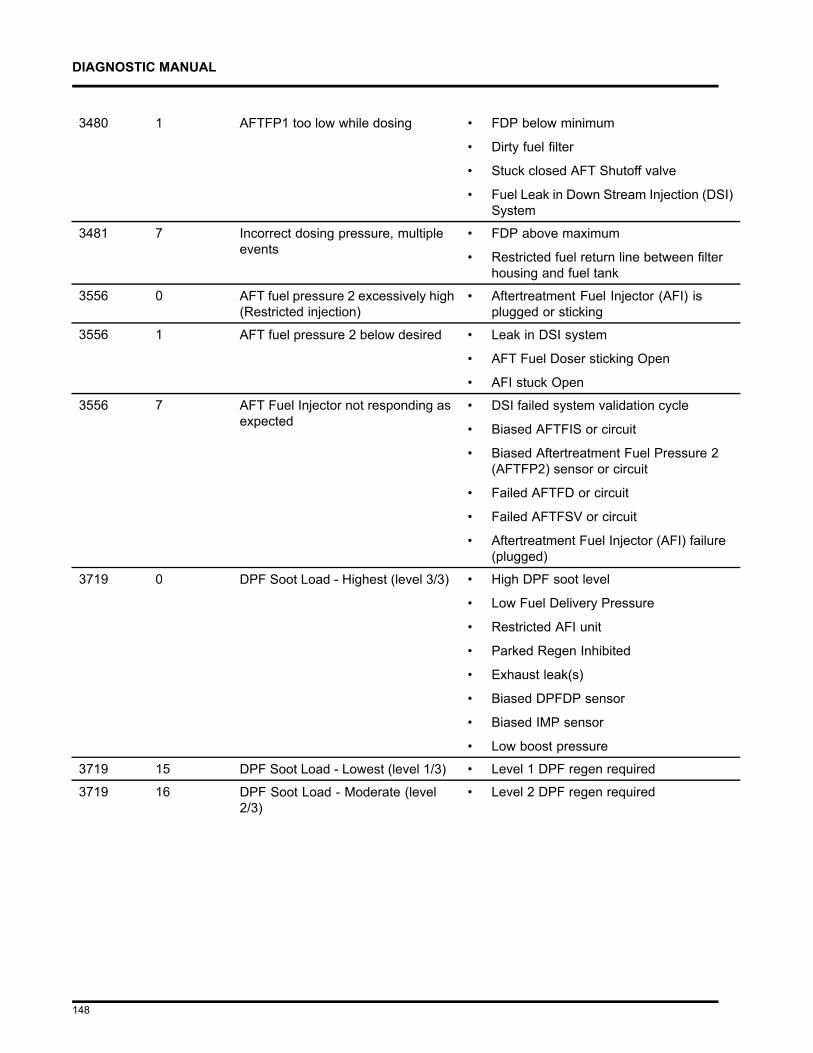
DIAGNOSTIC MANUAL
3480 1 AFTFP1 too low while dosing • FDP below minimum
• Dirty fuel filter
• Stuck closed AFT Shutoff valve
• Fuel Leak in Down Stream Injection (DSI)System
3481 7 Incorrect dosing pressure, multipleevents
• FDP above maximum
• Restricted fuel return line between filterhousing and fuel tank
3556 0 AFT fuel pressure 2 excessively high(Restricted injection)
• Aftertreatment Fuel Injector (AFI) isplugged or sticking
3556 1 AFT fuel pressure 2 below desired • Leak in DSI system
• AFT Fuel Doser sticking Open
• AFI stuck Open
3556 7 AFT Fuel Injector not responding asexpected
• DSI failed system validation cycle
• Biased AFTFIS or circuit
• Biased Aftertreatment Fuel Pressure 2(AFTFP2) sensor or circuit
• Failed AFTFD or circuit
• Failed AFTFSV or circuit
• Aftertreatment Fuel Injector (AFI) failure(plugged)
3719 0 DPF Soot Load - Highest (level 3/3) • High DPF soot level
• Low Fuel Delivery Pressure
• Restricted AFI unit
• Parked Regen Inhibited
• Exhaust leak(s)
• Biased DPFDP sensor
• Biased IMP sensor
• Low boost pressure
3719 15 DPF Soot Load - Lowest (level 1/3) • Level 1 DPF regen required
3719 16 DPF Soot Load - Moderate (level2/3)
• Level 2 DPF regen required
148
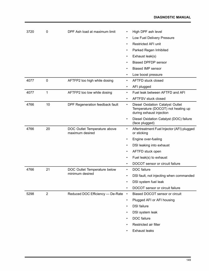
DIAGNOSTIC MANUAL
3720 0 DPF Ash load at maximum limit • High DPF ash level
• Low Fuel Delivery Pressure
• Restricted AFI unit
• Parked Regen Inhibited
• Exhaust leak(s)
• Biased DPFDP sensor
• Biased IMP sensor
• Low boost pressure
4077 0 AFTFP2 too high while dosing • AFTFD stuck closed
• AFI plugged
4077 1 AFTFP2 too low while dosing • Fuel leak between AFTFD and AFI
• AFTFSV stuck closed
4766 10 DPF Regeneration feedback fault • Diesel Oxidation Catalyst OutletTemperature (DOCOT) not heating upduring exhaust injection
• Diesel Oxidation Catalyst (DOC) failure(face plugged)
4766 20 DOC Outlet Temperature abovemaximum desired
• Aftertreatment Fuel Injector (AFI) pluggedor sticking
• Engine over-fueling
• DSI leaking into exhaust
• AFTFD stuck open
• Fuel leak(s) to exhaust
• DOCOT sensor or circuit failure
4766 21 DOC Outlet Temperature belowminimum desired
• DOC failure
• DSI fault, not injecting when commanded
• DSI system fuel leak
• DOCOT sensor or circuit failure
5298 2 Reduced DOC Efficiency — De-Rate • Biased DOCOT sensor or circuit
• Plugged AFI or AFI housing
• DSI failure
• DSI system leak
• DOC failure
• Restricted air filter
• Exhaust leaks
149
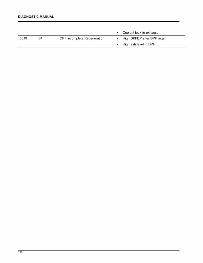
DIAGNOSTIC MANUAL
• Coolant leak to exhaust
5319 31 DPF incomplete Regeneration • High DPFDP after DPF regen
• High ash level in DPF
150
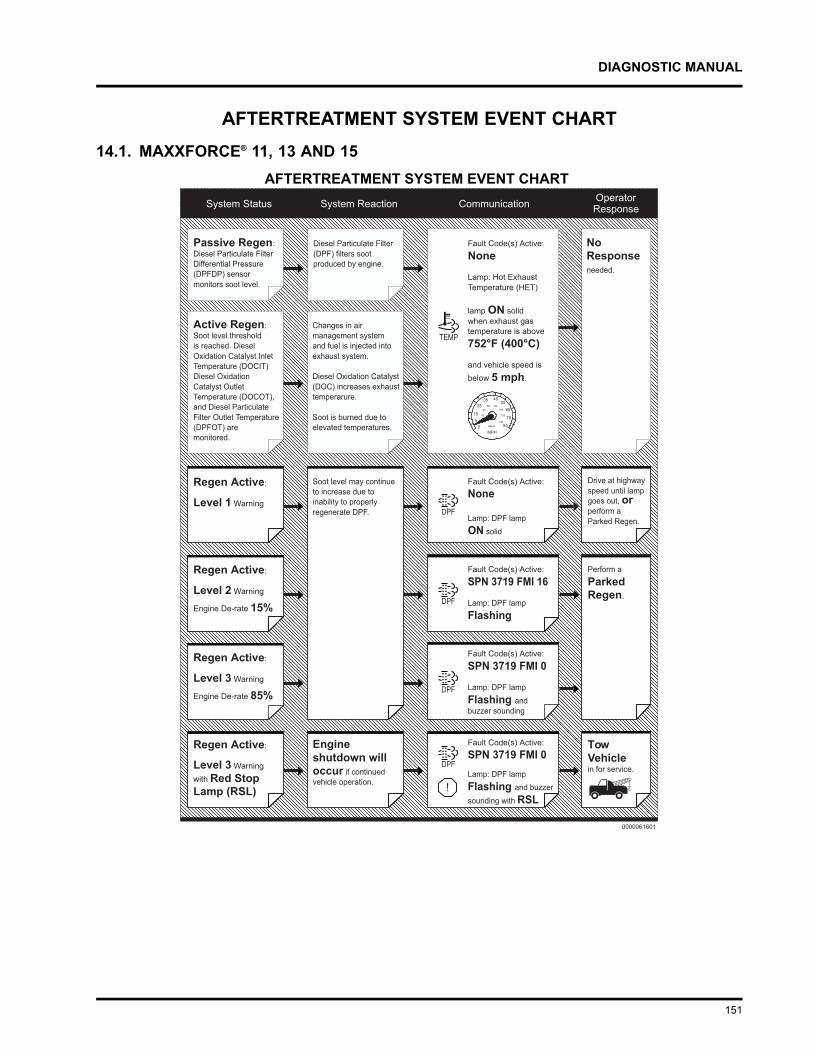
DIAGNOSTIC MANUAL
AFTERTREATMENT SYSTEM EVENT CHART14.1. MAXXFORCE® 11, 13 AND 15
151
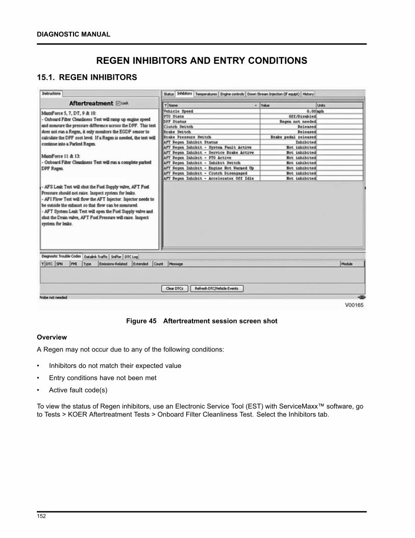
DIAGNOSTIC MANUAL
REGEN INHIBITORS AND ENTRY CONDITIONS15.1. REGEN INHIBITORS
Figure 45 Aftertreatment session screen shot
Overview
A Regen may not occur due to any of the following conditions:
• Inhibitors do not match their expected value
• Entry conditions have not been met
• Active fault code(s)
To view the status of Regen inhibitors, use an Electronic Service Tool (EST) with ServiceMaxx™ software, goto Tests > KOER Aftertreatment Tests > Onboard Filter Cleanliness Test. Select the Inhibitors tab.
152
DIAGNOSTIC MANUAL
NOTE – Any active aftertreatment system fault code(s) may inhibit a Regen. Diagnose active faultcode(s), other than SPN 3719 (DPF Soot Load), before continuing (see Electronic Control SystemsDiagnostics” in Engine Diagnostic Manual).
Table 182 Check Active Regen Inhibitors
1. Turn ignition switch to ON position, engine OFF.
2. Using ServiceMaxx™ software, load the Aftertreatment session.
3. Start engine and run vehicle speed above 5 mph.
4. Verify all listed inhibitors are displaying Not Inhibited.
Check Expected Results CommentAFT Regen InhibitStatus
Not Inhibited If inhibited, correct the cause. Check switches and any DTCthat may be causing the Regen inhibit.
Red Stop Alert Lamp Off If On, Regen can't be run. Go to appropriate aftertreatmentsystem diagnostics section in this manual.
Regen Inhibit Switch Off If On, turn switch Off. If switch does not turn Off, thendiagnose circuit fault.
PTO Enable Switch Off If On, turn switch Off. If switch does not turn Off, thendiagnose circuit fault.
PTO Switch Off If On, turn switch Off. If switch does not turn Off, thendiagnose circuit fault.
If no inhibitors are active and Regen is needed, go to Parked Regen Checks (page 155).
153
DIAGNOSTIC MANUAL
Table 183 Check Parked Regen Inhibitors
1. Turn ignition switch ON, engine OFF.
2. Using EST with ServiceMaxx™ software, load the Aftertreatment session.
3. Verify all listed Inhibitors are displaying Not Inhibited.
Checks Expected Results CommentAFT Regen Inhibit status Not Inhibited If inhibited, correct the cause. Check switches and any
DTC that may be causing the Regen inhibit.
Red Stop Alert lamp Off If On, Regen can't be run. Go to appropriate aftertreatmentsystem diagnostics section in this manual.
Regen inhibit switch Off If On, turn switch Off. If switch does not turn Off, thendiagnose circuit fault.
PTO enable switch Off If On, turn switch Off. If switch does not turn Off, thendiagnose circuit fault.
PTO switch Off If On, turn switch Off. If switch does not turn Off, thendiagnose circuit fault.
Parking brake switch On If Off, set parking brake, if switch does not turn On, thendiagnose circuit fault.
Brake Pedal switch Off If On and foot is off pedal, then diagnose circuit fault.
Accelerator PedalPosition
0% If above 0%, and foot is off pedal, then diagnose circuitfault.
Clutch Pedal Switch Off If On and foot is off pedal, then diagnose circuit fault.
Transmission Position Park or Neutral If engaged, disengage, or diagnose circuit fault.
If no inhibitors and a Regen is needed, go to the following Parked Regen Checks.
Parked Regen Checks
During a Parked Regen the engine speed will ramp up to 1200-1800 rpm.
Typical readings:
• ETV: 80% (closed).
• EGR Position: 0% (closed)
• DOCIT: 482 - 572°F (250-300°C)
• DOCOT: 1112 - 1202°F (600–650°C) (after 5-10 minutes)
• DPFOT: 1022 - 1112°F (550–600°C) (after 10-15 minutes)
• DPFDP: Decreasing steadily once DPFIT and DPFOT are steady and above 1022°F (550°C).
Using EST with ServiceMaxx™ software, open the Aftertreatment session. Start a Parked Regen andmonitor signals.
154
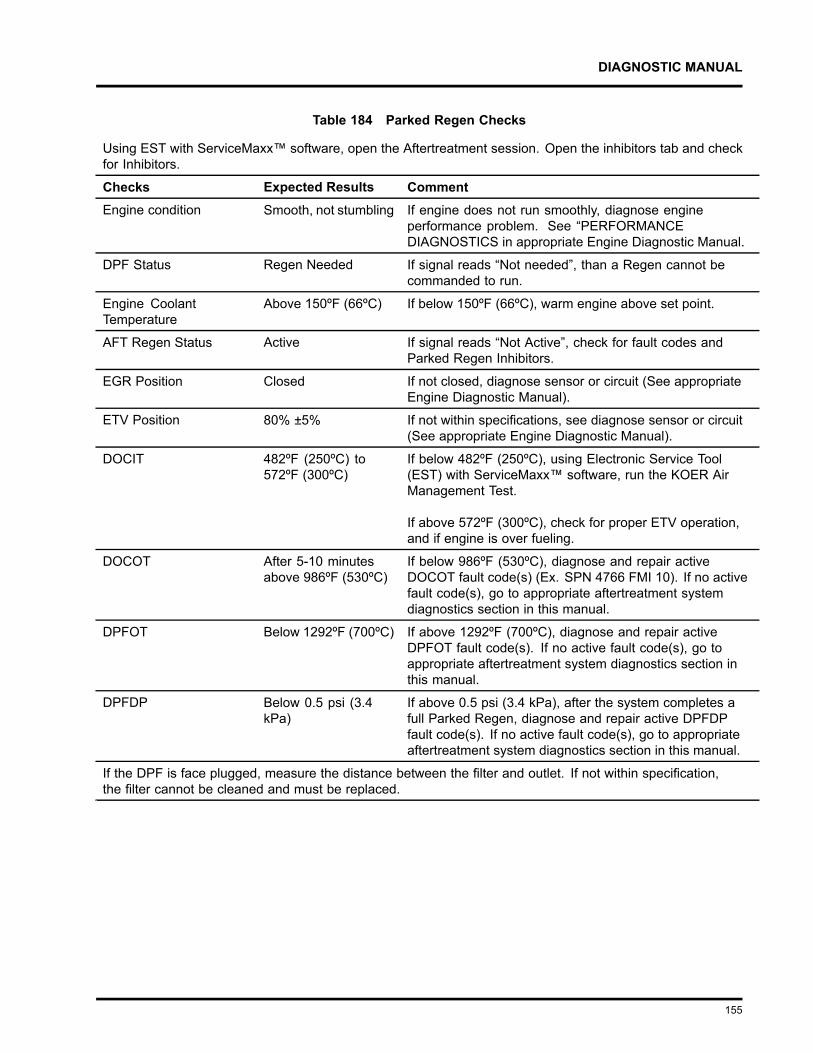
DIAGNOSTIC MANUAL
Table 184 Parked Regen Checks
Using EST with ServiceMaxx™ software, open the Aftertreatment session. Open the inhibitors tab and checkfor Inhibitors.
Checks Expected Results CommentEngine condition Smooth, not stumbling If engine does not run smoothly, diagnose engine
performance problem. See “PERFORMANCEDIAGNOSTICS in appropriate Engine Diagnostic Manual.
DPF Status Regen Needed If signal reads “Not needed”, than a Regen cannot becommanded to run.
Engine CoolantTemperature
Above 150ºF (66ºC) If below 150ºF (66ºC), warm engine above set point.
AFT Regen Status Active If signal reads “Not Active”, check for fault codes andParked Regen Inhibitors.
EGR Position Closed If not closed, diagnose sensor or circuit (See appropriateEngine Diagnostic Manual).
ETV Position 80% ±5% If not within specifications, see diagnose sensor or circuit(See appropriate Engine Diagnostic Manual).
DOCIT 482ºF (250ºC) to572ºF (300ºC)
If below 482ºF (250ºC), using Electronic Service Tool(EST) with ServiceMaxx™ software, run the KOER AirManagement Test.
If above 572ºF (300ºC), check for proper ETV operation,and if engine is over fueling.
DOCOT After 5-10 minutesabove 986ºF (530ºC)
If below 986ºF (530ºC), diagnose and repair activeDOCOT fault code(s) (Ex. SPN 4766 FMI 10). If no activefault code(s), go to appropriate aftertreatment systemdiagnostics section in this manual.
DPFOT Below 1292ºF (700ºC) If above 1292ºF (700ºC), diagnose and repair activeDPFOT fault code(s). If no active fault code(s), go toappropriate aftertreatment system diagnostics section inthis manual.
DPFDP Below 0.5 psi (3.4kPa)
If above 0.5 psi (3.4 kPa), after the system completes afull Parked Regen, diagnose and repair active DPFDPfault code(s). If no active fault code(s), go to appropriateaftertreatment system diagnostics section in this manual.
If the DPF is face plugged, measure the distance between the filter and outlet. If not within specification,the filter cannot be cleaned and must be replaced.
155
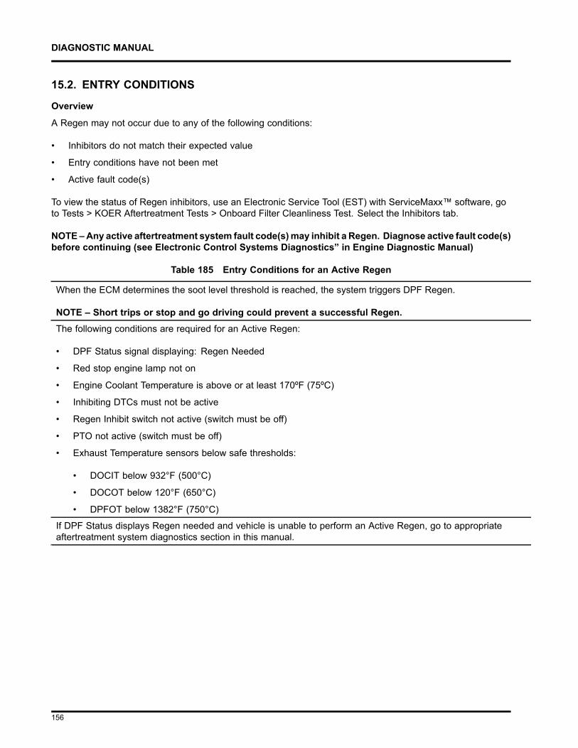
DIAGNOSTIC MANUAL
15.2. ENTRY CONDITIONS
Overview
A Regen may not occur due to any of the following conditions:
• Inhibitors do not match their expected value
• Entry conditions have not been met
• Active fault code(s)
To view the status of Regen inhibitors, use an Electronic Service Tool (EST) with ServiceMaxx™ software, goto Tests > KOER Aftertreatment Tests > Onboard Filter Cleanliness Test. Select the Inhibitors tab.
NOTE –Any active aftertreatment system fault code(s)may inhibit a Regen. Diagnose active fault code(s)before continuing (see Electronic Control Systems Diagnostics” in Engine Diagnostic Manual)
Table 185 Entry Conditions for an Active Regen
When the ECM determines the soot level threshold is reached, the system triggers DPF Regen.
NOTE – Short trips or stop and go driving could prevent a successful Regen.The following conditions are required for an Active Regen:
• DPF Status signal displaying: Regen Needed
• Red stop engine lamp not on
• Engine Coolant Temperature is above or at least 170ºF (75ºC)
• Inhibiting DTCs must not be active
• Regen Inhibit switch not active (switch must be off)
• PTO not active (switch must be off)
• Exhaust Temperature sensors below safe thresholds:
• DOCIT below 932°F (500°C)
• DOCOT below 120°F (650°C)
• DPFOT below 1382°F (750°C)
If DPF Status displays Regen needed and vehicle is unable to perform an Active Regen, go to appropriateaftertreatment system diagnostics section in this manual.
156
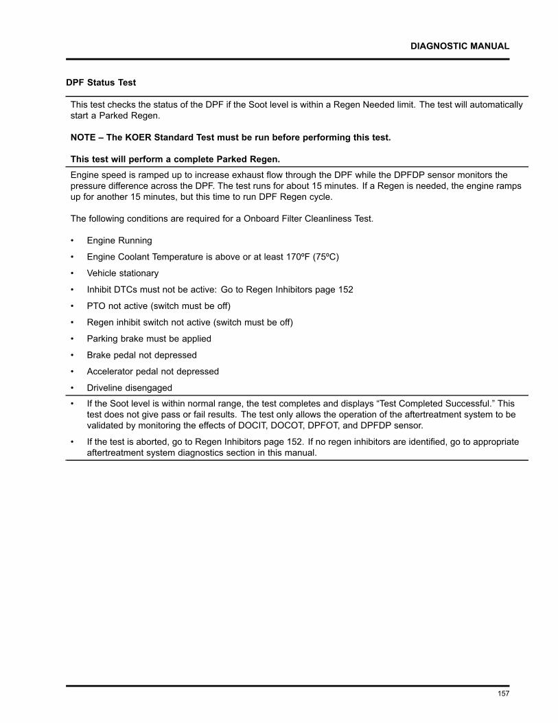
DIAGNOSTIC MANUAL
DPF Status Test
This test checks the status of the DPF if the Soot level is within a Regen Needed limit. The test will automaticallystart a Parked Regen.
NOTE – The KOER Standard Test must be run before performing this test.
This test will perform a complete Parked Regen.Engine speed is ramped up to increase exhaust flow through the DPF while the DPFDP sensor monitors thepressure difference across the DPF. The test runs for about 15 minutes. If a Regen is needed, the engine rampsup for another 15 minutes, but this time to run DPF Regen cycle.
The following conditions are required for a Onboard Filter Cleanliness Test.
• Engine Running
• Engine Coolant Temperature is above or at least 170ºF (75ºC)
• Vehicle stationary
• Inhibit DTCs must not be active: Go to Regen Inhibitors page 152
• PTO not active (switch must be off)
• Regen inhibit switch not active (switch must be off)
• Parking brake must be applied
• Brake pedal not depressed
• Accelerator pedal not depressed
• Driveline disengaged
• If the Soot level is within normal range, the test completes and displays “Test Completed Successful.” Thistest does not give pass or fail results. The test only allows the operation of the aftertreatment system to bevalidated by monitoring the effects of DOCIT, DOCOT, DPFOT, and DPFDP sensor.
• If the test is aborted, go to Regen Inhibitors page 152. If no regen inhibitors are identified, go to appropriateaftertreatment system diagnostics section in this manual.
157
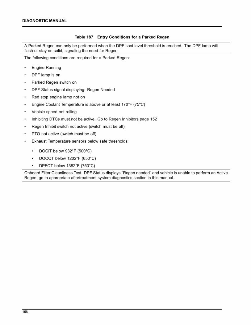
DIAGNOSTIC MANUAL
Table 187 Entry Conditions for a Parked Regen
A Parked Regen can only be performed when the DPF soot level threshold is reached. The DPF lamp willflash or stay on solid, signaling the need for Regen.
The following conditions are required for a Parked Regen:
• Engine Running
• DPF lamp is on
• Parked Regen switch on
• DPF Status signal displaying: Regen Needed
• Red stop engine lamp not on
• Engine Coolant Temperature is above or at least 170ºF (75ºC)
• Vehicle speed not rolling
• Inhibiting DTCs must not be active. Go to Regen Inhibitors page 152
• Regen Inhibit switch not active (switch must be off)
• PTO not active (switch must be off)
• Exhaust Temperature sensors below safe thresholds:
• DOCIT below 932°F (500°C)
• DOCOT below 1202°F (650°C)
• DPFOT below 1382°F (750°C)
Onboard Filter Cleanliness Test. DPF Status displays “Regen needed” and vehicle is unable to perform an ActiveRegen, go to appropriate aftertreatment system diagnostics section in this manual.
158
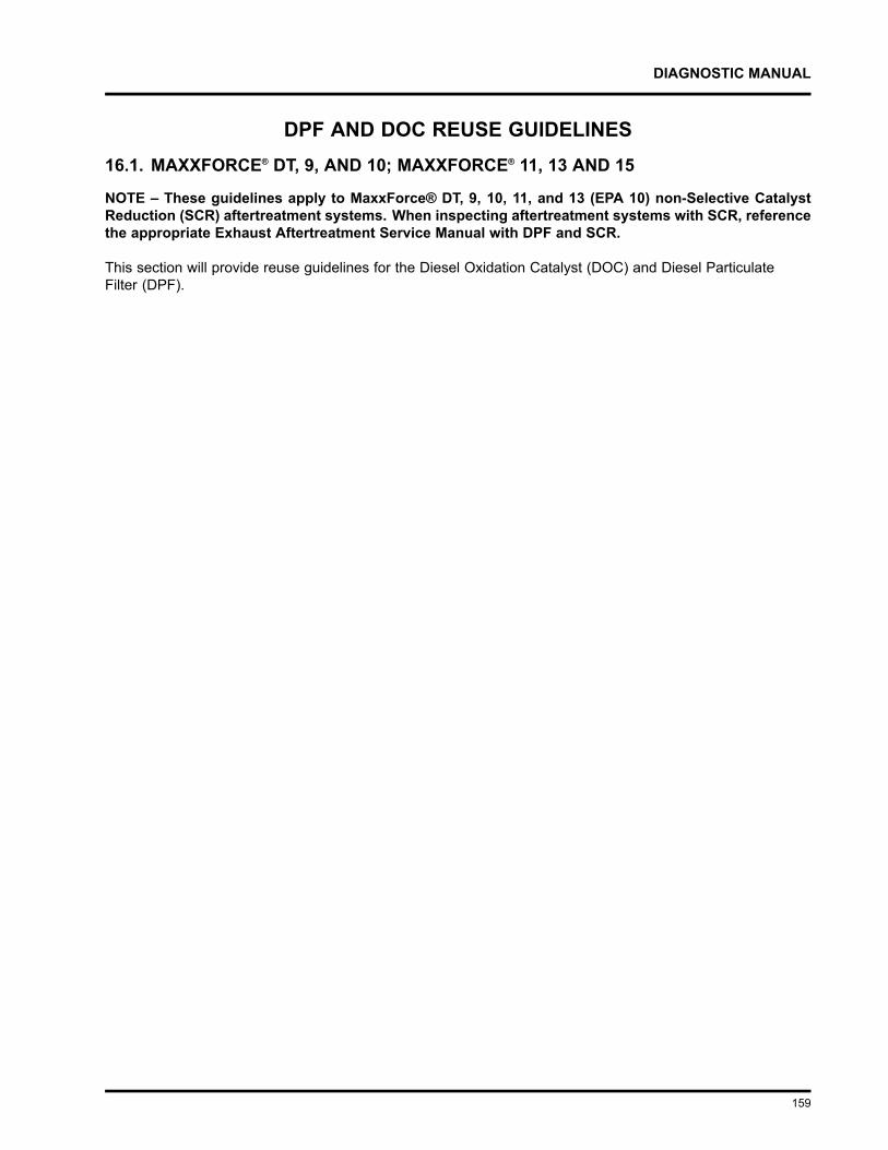
DIAGNOSTIC MANUAL
DPF AND DOC REUSE GUIDELINES16.1. MAXXFORCE® DT, 9, AND 10; MAXXFORCE® 11, 13 AND 15
NOTE – These guidelines apply to MaxxForce® DT, 9, 10, 11, and 13 (EPA 10) non-Selective CatalystReduction (SCR) aftertreatment systems. When inspecting aftertreatment systems with SCR, referencethe appropriate Exhaust Aftertreatment Service Manual with DPF and SCR.
This section will provide reuse guidelines for the Diesel Oxidation Catalyst (DOC) and Diesel ParticulateFilter (DPF).
159
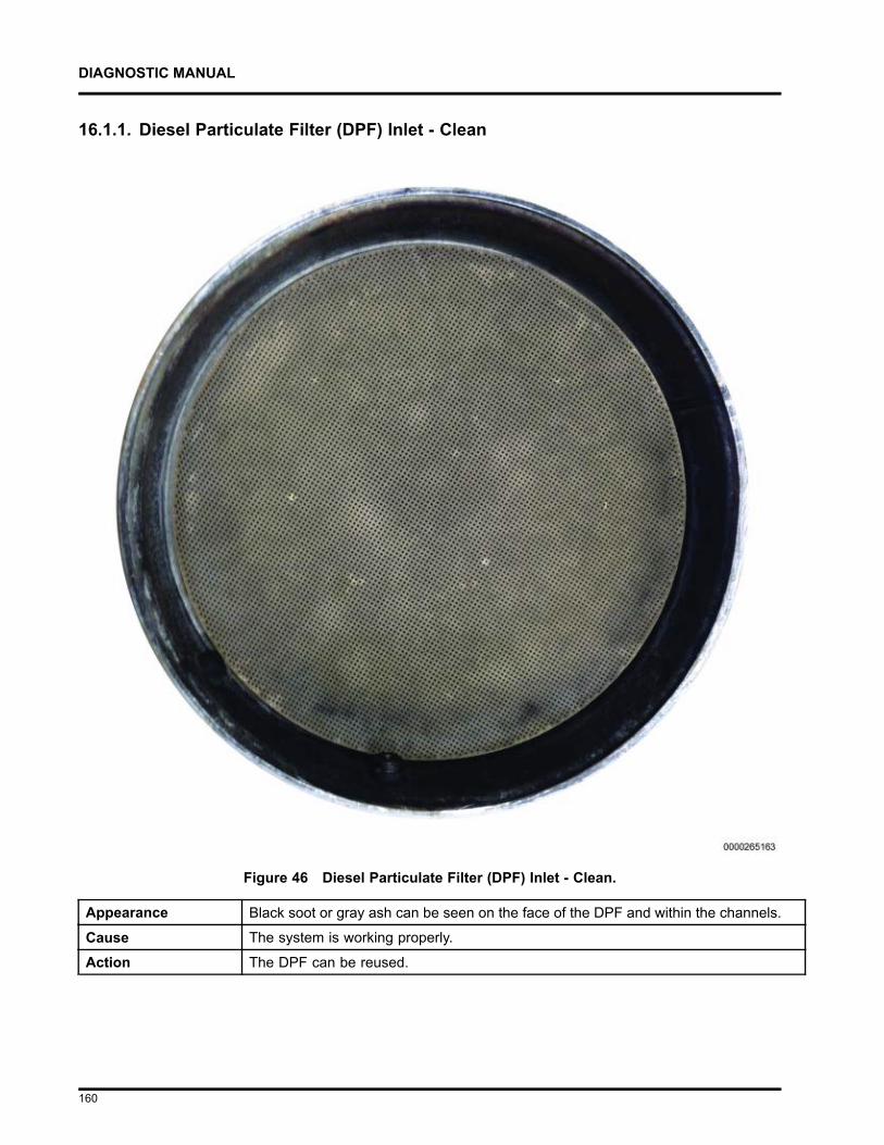
DIAGNOSTIC MANUAL
16.1.1. Diesel Particulate Filter (DPF) Inlet - Clean
Figure 46 Diesel Particulate Filter (DPF) Inlet - Clean.
Appearance Black soot or gray ash can be seen on the face of the DPF and within the channels.
Cause The system is working properly.
Action The DPF can be reused.
160
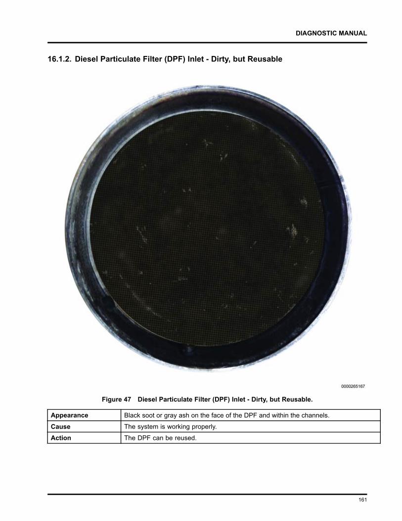
DIAGNOSTIC MANUAL
16.1.2. Diesel Particulate Filter (DPF) Inlet - Dirty, but Reusable
Figure 47 Diesel Particulate Filter (DPF) Inlet - Dirty, but Reusable.
Appearance Black soot or gray ash on the face of the DPF and within the channels.
Cause The system is working properly.
Action The DPF can be reused.
161
DIAGNOSTIC MANUAL
16.1.3. Diesel Particulate Filter (DPF) Inlet - Face Plugged
Figure 48 Diesel Particulate Filter (DPF) Inlet - Face Plugged.
Appearance The DPF is completely covered with black soot or gray ash.
Cause Excessive soot generation.
Action Determine and repair the root cause of excessive soot generation. Once the root causeis repaired, properly service and reuse the DPF.
162
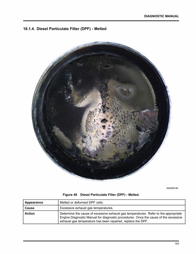
DIAGNOSTIC MANUAL
16.1.4. Diesel Particulate Filter (DPF) - Melted
Figure 49 Diesel Particulate Filter (DPF) - Melted.
Appearance Melted or deformed DPF cells.
Cause Excessive exhaust gas temperatures.
Action Determine the cause of excessive exhaust gas temperatures. Refer to the appropriateEngine Diagnostic Manual for diagnostic procedures. Once the cause of the excessiveexhaust gas temperature has been repaired, replace the DPF.
163
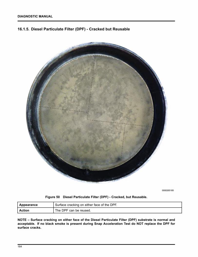
DIAGNOSTIC MANUAL
16.1.5. Diesel Particulate Filter (DPF) - Cracked but Reusable
Figure 50 Diesel Particulate Filter (DPF) - Cracked, but Reusable.
Appearance Surface cracking on either face of the DPF.
Action The DPF can be reused.
NOTE – Surface cracking on either face of the Diesel Particulate Filter (DPF) substrate is normal andacceptable. If no black smoke is present during Snap Acceleration Test do NOT replace the DPF forsurface cracks.
164
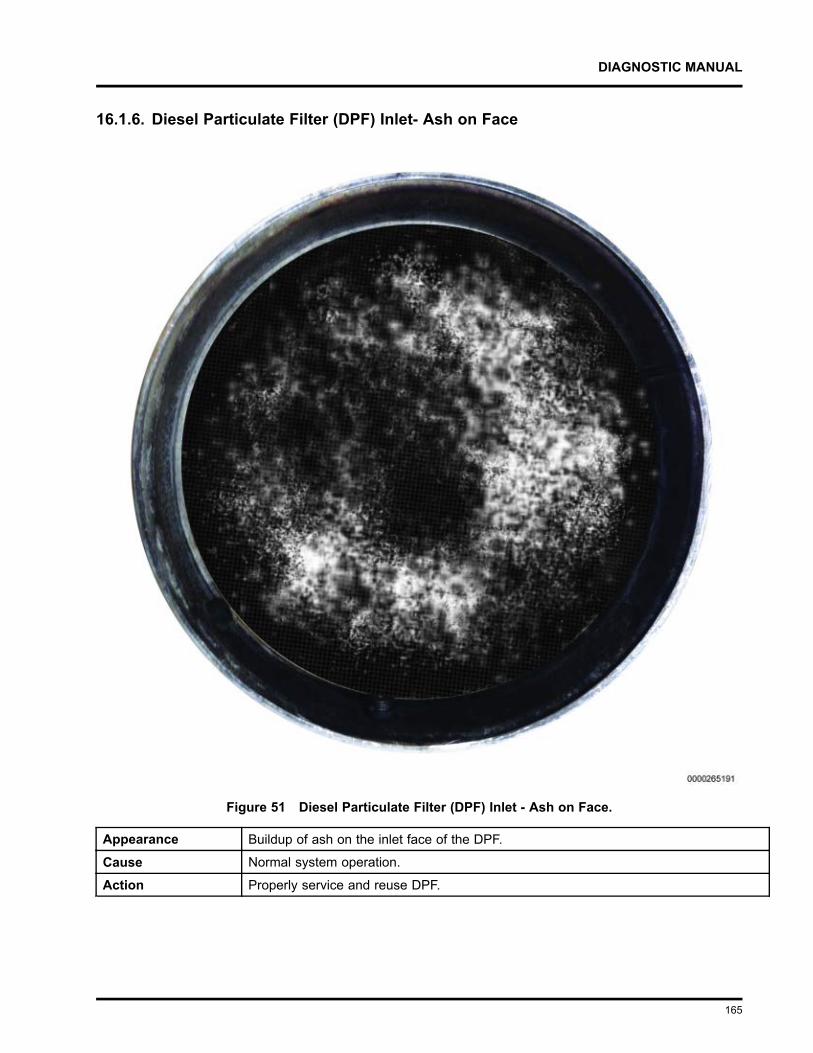
DIAGNOSTIC MANUAL
16.1.6. Diesel Particulate Filter (DPF) Inlet- Ash on Face
Figure 51 Diesel Particulate Filter (DPF) Inlet - Ash on Face.
Appearance Buildup of ash on the inlet face of the DPF.
Cause Normal system operation.
Action Properly service and reuse DPF.
165
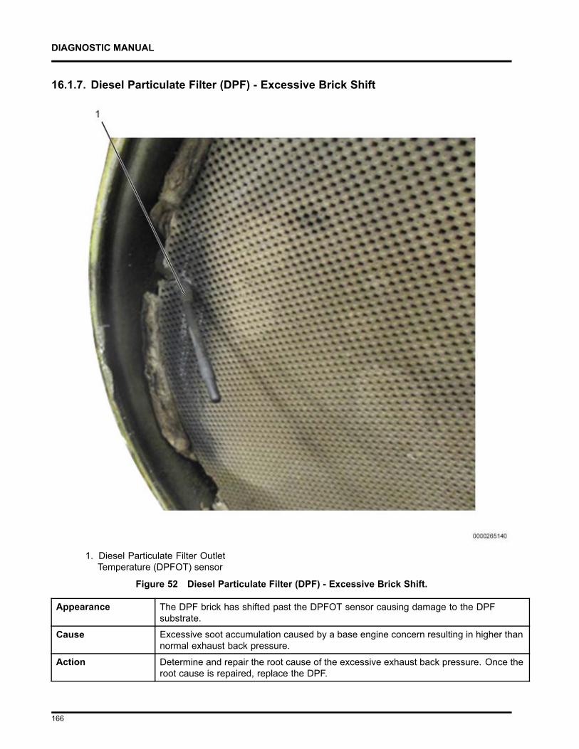
DIAGNOSTIC MANUAL
16.1.7. Diesel Particulate Filter (DPF) - Excessive Brick Shift
1. Diesel Particulate Filter OutletTemperature (DPFOT) sensor
Figure 52 Diesel Particulate Filter (DPF) - Excessive Brick Shift.
Appearance The DPF brick has shifted past the DPFOT sensor causing damage to the DPFsubstrate.
Cause Excessive soot accumulation caused by a base engine concern resulting in higher thannormal exhaust back pressure.
Action Determine and repair the root cause of the excessive exhaust back pressure. Once theroot cause is repaired, replace the DPF.
166
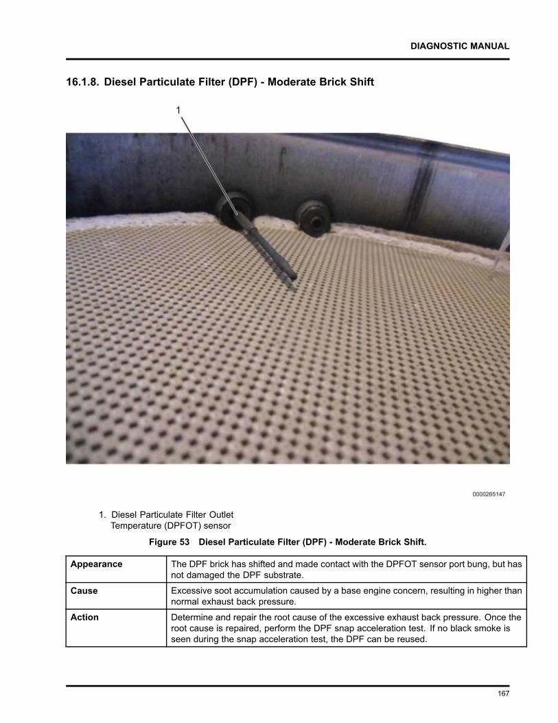
DIAGNOSTIC MANUAL
16.1.8. Diesel Particulate Filter (DPF) - Moderate Brick Shift
1. Diesel Particulate Filter OutletTemperature (DPFOT) sensor
Figure 53 Diesel Particulate Filter (DPF) - Moderate Brick Shift.
Appearance The DPF brick has shifted and made contact with the DPFOT sensor port bung, but hasnot damaged the DPF substrate.
Cause Excessive soot accumulation caused by a base engine concern, resulting in higher thannormal exhaust back pressure.
Action Determine and repair the root cause of the excessive exhaust back pressure. Once theroot cause is repaired, perform the DPF snap acceleration test. If no black smoke isseen during the snap acceleration test, the DPF can be reused.
167
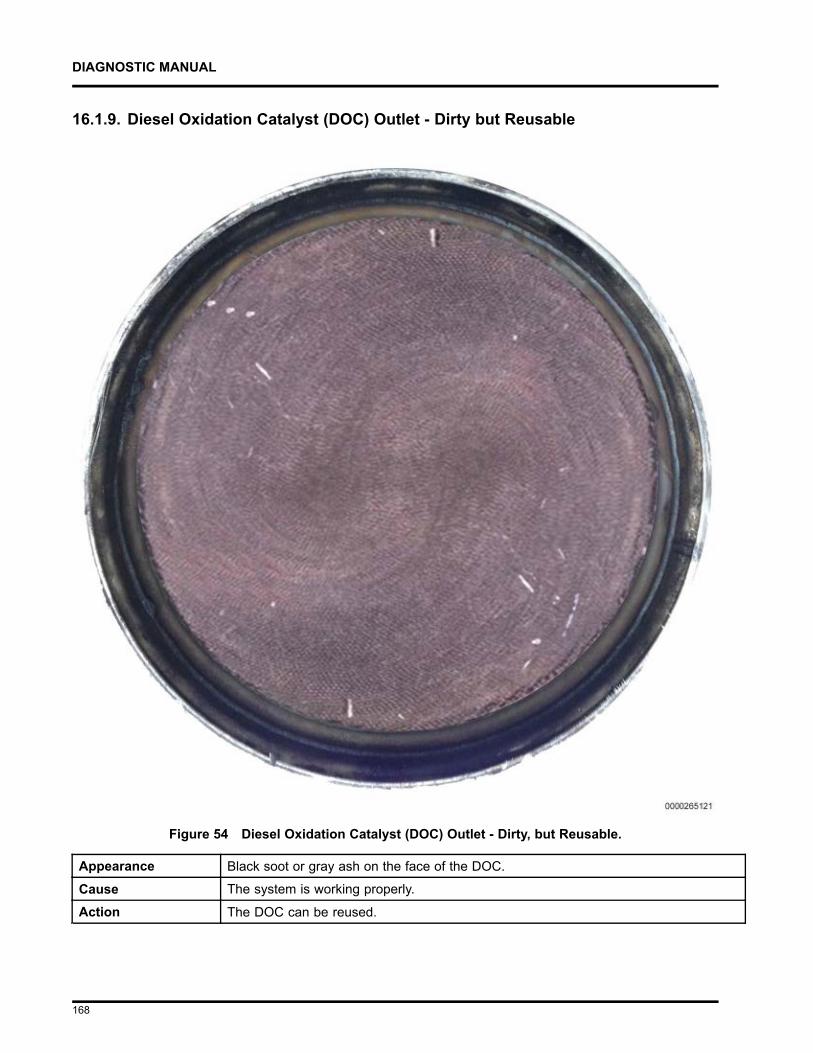
DIAGNOSTIC MANUAL
16.1.9. Diesel Oxidation Catalyst (DOC) Outlet - Dirty but Reusable
Figure 54 Diesel Oxidation Catalyst (DOC) Outlet - Dirty, but Reusable.
Appearance Black soot or gray ash on the face of the DOC.
Cause The system is working properly.
Action The DOC can be reused.
168
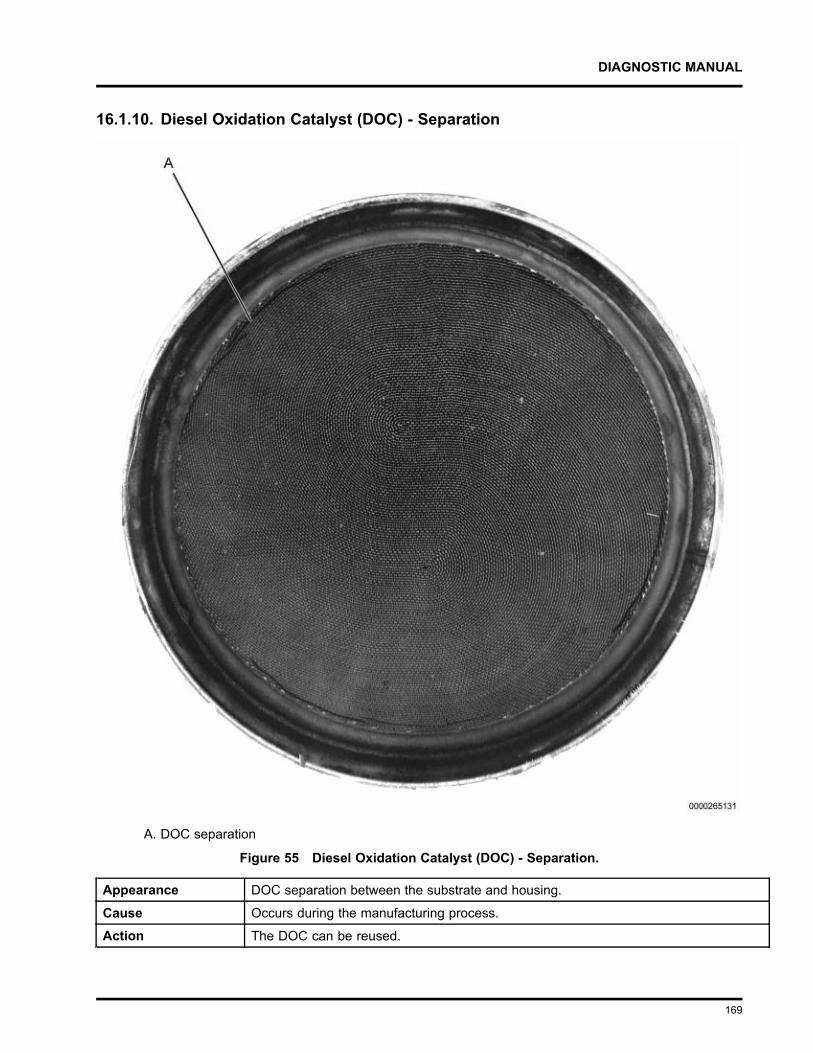
DIAGNOSTIC MANUAL
16.1.10. Diesel Oxidation Catalyst (DOC) - Separation
A. DOC separation
Figure 55 Diesel Oxidation Catalyst (DOC) - Separation.
Appearance DOC separation between the substrate and housing.
Cause Occurs during the manufacturing process.
Action The DOC can be reused.
169
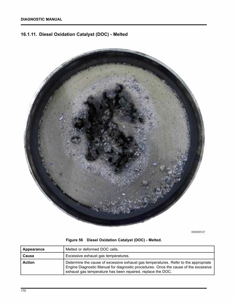
DIAGNOSTIC MANUAL
16.1.11. Diesel Oxidation Catalyst (DOC) - Melted
Figure 56 Diesel Oxidation Catalyst (DOC) - Melted.
Appearance Melted or deformed DOC cells.
Cause Excessive exhaust gas temperatures.
Action Determine the cause of excessive exhaust gas temperatures. Refer to the appropriateEngine Diagnostic Manual for diagnostic procedures. Once the cause of the excessiveexhaust gas temperature has been repaired, replace the DOC.
170
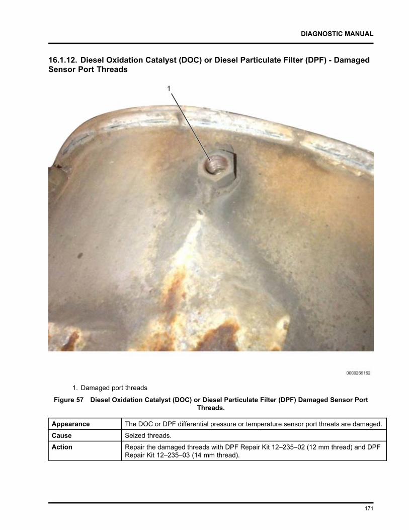
DIAGNOSTIC MANUAL
16.1.12. Diesel Oxidation Catalyst (DOC) or Diesel Particulate Filter (DPF) - DamagedSensor Port Threads
1. Damaged port threads
Figure 57 Diesel Oxidation Catalyst (DOC) or Diesel Particulate Filter (DPF) Damaged Sensor PortThreads.
Appearance The DOC or DPF differential pressure or temperature sensor port threats are damaged.
Cause Seized threads.
Action Repair the damaged threads with DPF Repair Kit 12–235–02 (12 mm thread) and DPFRepair Kit 12–235–03 (14 mm thread).
171
DIAGNOSTIC MANUAL
ABBREVIATIONS AND ACRONYMSA or amp
AmpereAAT
Ambient Air TemperatureABDC
After Bottom Dead CenterABS
Antilock Brake SystemAC
Alternating CurrentACCEL
AcceleratorACM
Aftertreatment Control ModuleACV
Air Control ValveA/F
Air to Fuel ratioAFI
Aftertreatment Fuel InjectorAFP
Aftertreatment Fuel PressureAFS
Aftertreatment Fuel SupplyAFT
AftertreatmentAFTFD
Aftertreatment Fuel DoserAFTFIT
Aftertreatment Fuel Inlet TemperatureAFTFIS
Aftertreatment Fuel Inlet SensorAFTFP
Aftertreatment Fuel PressureAFTFP1
Aftertreatment Fuel Pressure 1AFTFP2
Aftertreatment Fuel Pressure 2AFTFSV
Aftertreatment Fuel Shutoff ValveAmb
Ambientamp or A
AmpereAMS
Air Management SystemAPP
Accelerator Pedal PositionAPP1
Accelerator Pedal Position 1APP2
Accelerator Pedal Position 2
172
DIAGNOSTIC MANUAL
APSAccelerator Position Sensor
APS/IVSAccelerator Position Sensor / Idle Validation Switch
ATAAmerican Trucking Association
ATDCAfter Top Dead Center
AWLAmber Warning Lamp
B+ or VBATBattery Voltage
BAP or BAROBarometric Absolute Pressure
BBDCBefore Bottom Dead Center
BCBody Controller
BCSBoost Control Solenoid
BDCBottom Dead Center
bhpBrake Horsepower
BOOBrake On / Off
BTDCBefore Top Dead Center
CCelsius
CACCharge Air Cooler
CACOTCharge Air Cooler Outlet Temperature
CANController Area Network
CAPCold Ambient Protection
CARBCalifornia Air Resources Board
ccCubic centimeter
CCACold Cranking Ampere
CCVCoolant Control Valve
CCOSCrankcase Oil Separator (breather)
CCPSCrankcase Pressure Sensor
CCSCruise Control Switches
173
DIAGNOSTIC MANUAL
cfmCubic feet per minute
cfsCubic feet per second
CFVCoolant Flow Valve
CKPCrankshaft Position
cmCentimeter
CMPCamshaft Position
CMVCoolant Mixer Valve
COCarbon Monoxide
CylCylinder
DCDirect Current
DLCData Link Connector
DMMDigital Multimeter
DOCDiesel Oxidation Catalyst
DOCITDiesel Oxidation Catalyst Inlet Temperature
DOCOTDiesel Oxidation Catalyst Outlet Temperature
DPFDiesel Particulate Filter
DPFDPDiesel Particulate Filter Differential Pressure
DPFITDiesel Particulate Filter Inlet Temperature
DPFOTDiesel Particulate Filter Outlet Temperature
DSIDown Stream Injection
DTCDiagnostic Trouble Code
DTCsDiagnostic Trouble Codes
EBPExhaust Back Pressure
EBPVExhaust Back Pressure Valve
ECBEngine Compression Brake
ECLEngine Coolant Level
174
DIAGNOSTIC MANUAL
ECMEngine Control Module
ECTEngine Coolant Temperature
ECT1Engine Coolant Temperature 1
ECT2Engine Coolant Temperature 2
EGRExhaust Gas Recirculation
EGTExhaust Gas Temperature
EGT1Exhaust Gas Temperature 1
EGT2Exhaust Gas Temperature 2
EGT3Exhaust Gas Temperature 3
EMIElectromagnetic Interference
EOPEngine Oil Pressure
EOTEngine Oil Temperature
EPAEnvironmental Protection Agency
ESNEngine Serial Number
ESTElectronic Service Tool
ETCEngine Throttle Control
ETPEngine Throttle Position
ETVEngine Throttle Valve
EVBExhaust Valve Brake
EWPSEngine Warning Protection System
FFahrenheit
FCVFuel Coolant Valve
FDPFuel Delivery Pressure
fhpFriction horsepower
FMIFailure Mode Indicator
FPCFuel Pump Control
175
DIAGNOSTIC MANUAL
FPCVFuel Pressure Control Valve
fpmFeet per minute
fpsFeet per second
FRPFuel Rail Pressure
FRPDFuel Rail Pressure Desired
ftFeet
GNDGround (electrical)
galGallon
gal/hU.S. Gallons per hour
gal/minU.S. Gallons per minute
GCWGross Combined Weight
GCWRGross Combined Weight Rating
GVWGross Vehicle Weight
H2OWater
HCHydrocarbons
HCIHydrocarbon Injection
HESTHigh Exhaust System Temperature
HgMercury
hpHorsepower
HPCACHigh-Pressure Charge Air Cooler
HPCRHigh-Pressure Common Rail
HPFPHigh-Pressure Fuel Pump
hrHour
HSHumidity Sensor
HydHydraulic
176
DIAGNOSTIC MANUAL
IAHInlet Air Heater
IAHRInlet Air Heater Relay
IATInlet Air Temperature
ICIntegrated Circuit
ICPInjection Control Pressure
ICPRInjection Control Pressure Regulator
IGNIgnition
IMPIntake Manifold Pressure
IMTIntake Manifold Temperature
inInch
inHgInch of mercury
INJsInjectors
IPRInjection Pressure Regulator
ISCInterstage Cooler
ITVIntake Throttle Valve
J1939HJ1939 Data Link High
J1939LJ1939 Data Link Low
kgKilogram
kmKilometer
km/hKilometers per hour
KOEOKey-On Engine-Off
KOERKey-On Engine-Running
kPaKilopascal
LLiter
lbPound
lbfPounds of force
177
DIAGNOSTIC MANUAL
lb/sPounds per second
lbf ftPounds of force per foot
lb inPounds of force per inch
lbmPounds of mass
LPCACLow-pressure Charge Air Cooler
LSDLow Sulfur Diesel
mMeter
m/sMeters per second
MAFMass Air Flow
MAPManifold Absolute Pressure
MAP/IATManifold Absolute Pressure / Inlet Air Temperature
miMile
MILMalfunction Indicator Lamp
mmMillimeter
mpgMiles per gallon
mphMiles per hour
MSDSMaterial Safety Data Sheet
MSMMultiplex System Module
MYModel Year
NCNormally Closed (electrical)
NmNewton meter
NONormally Open (electrical)
NOX
Nitrogen Oxides
O2SOxygen Sensor
O2SHOxygen Sensor Heater
178
DIAGNOSTIC MANUAL
OSHAOccupational Safety and Health Administration
OWLOil/Water Lamp
PIDParameter Identifier
P/NPart Number
PDOCPre-Diesel Oxidation Catalyst
ppmParts per million
PROMProgrammable Read Only Memory
psiPounds per square inch
psiaPounds per square inch absolute
psigPounds per square inch gauge
ptPint
PTOPower Takeoff
PWMPulse Width Modulate
PWRPower (voltage)
qtQuart
RAMRandom Access Memory
rpmRevolutions per minute
SIG GNDSignal Ground
S/NSerial Number
SPEEDOSpeedometer
SPNSuspect Parameter Number
SWBATSwitch Battery
TC2CISTurbocharger 2 Compressor Inlet Sensor
TC1TOPTurbocharger 1 Turbine Outlet Pressure
TC2TOPTurbocharger 2 Turbine Outlet Pressure
179
DIAGNOSTIC MANUAL
TC1WCTurbocharger 1 Wastegate Control
TC2WCTurbocharger 2 Wastegate Control
TCMTransmission Control Module
TDCTop Dead Center
VVolt
VBAT or B+Battery Voltage
VGTVariable Geometry Turbo
VINVehicle Identification Number
VREFReference Voltage
VSSVehicle Speed Sensor
WTSLWait to Start Lamp
WIFWater In Fuel
WIFLWater In Fuel Lamp
180
DIAGNOSTIC MANUAL
TERMINOLOGYAccelerator Pedal Position(APP) sensor
A potentiometer sensor that indicates the position of the throttle pedal.
ActuatorA device that performs work in response to an input signal.
Actuator ControlThe ECM controls the actuators by applying a low-level signal (low-side driver) or a high-level signal (highside driver). When switched on, both drivers complete a ground or power circuit to an actuator.
AerationThe entrainment of air or combustion gas in coolant, lubricant, or fuel.
Aftercooler (Charge Air Cooler)A heat exchanger mounted in the charge air path between the turbocharger and engine intake manifold.The aftercooler reduces the charge air temperature by transferring heat from the charge air to a coolingmedium (usually air).
Aftertreatment Fuel Doser(AFTFD)
A part of the Down Stream Injection (DSI) unit that sends pressurized fuel to the Aftertreatment FuelInjector (AFI) to inject fuel into the exhaust pipe.
Aftertreatment Fuel Injector(AFI)
Injects fuel into the exhaust system to increase temperature of the exhaust gases.
Aftertreatment (AFT) systemA part of the exhaust system that processes engine exhaust to meet emission requirements and trapsparticulate matter (soot) to prevent it from leaving the tailpipe.
Air Control Valve (ACV)Contains the LP turbocharger wastegate control port, HP turbocharger wastegate control port, the EBPVcontrol port, and the TC1TOP port. Although these components are integral to the ACV, each circuit iscontrolled by the ECM. The ACV controls compressed air for each control valve.
Ambient temperatureThe environmental air temperature in which a unit is operating. In general, the temperature is measured inthe shade (no solar radiation) and represents the air temperature for other engine cooling performancemeasurement purposes. Air entering the radiator may or may not be the same ambient due to possibleheating from other sources or recirculation. (SAE J1004 SEP81)
Ampere (amp)The standard unit for measuring the strength of an electrical current. The flow rate of a charge in aconductor or conducting medium of one coulomb per second. (SAE J1213 NOV82)
AnalogA continuously variable voltage.
181
DIAGNOSTIC MANUAL
American Trucking Association(ATA) Datalink
A serial datalink specified by the American Trucking Association and the SAE.
Boost pressure1. The pressure of the charge air leaving the turbocharger.
2. Inlet manifold pressure that is greater than atmospheric pressure. Obtained by turbocharging.
Bottom Dead Center (BDC)The lowest position of the piston during the stroke.
Brake Horsepower (bhp)The power output from an engine, not the indicated horsepower. The power output of an engine,sometimes-called flywheel horsepower, is less than the indicated horsepower by the amount of frictionhorsepower consumed in the engine.
Brake Horsepower (bhp) netNet brake horsepower is measured with all engine components. The power of an engine when configuredas a fully equipped engine. (SAE J1349 JUN90)
CalibrationECM programming strategy to solve engine performance equations and make decisions. Calibrationvalues are stored in ROM and put into the processor during programming to allow the engine to operatewithin certain parameters.
Camshaft Position (CMP)sensor
A magnetic pickup sensor that provides the ECM with a camshaft speed and position signal.
Carbon Monoxide (CO)A colorless, odorless, highly poisonous gas that is formed by the incomplete combustion of carbon burningdiesel engine. It is present in the exhaust gases of diesel engines.
CatalystA substance that produces a chemical reaction without undergoing a chemical change itself.
Catalytic converterAn antipollution device in the exhaust system that contains a catalyst for chemically converting somepollutants in the exhaust gases (carbon monoxide, unburned hydrocarbons, and oxides of nitrogen) intoharmless compounds.
Charge airDense, pressurized, heated air discharged from the turbocharger.
Charge Air Cooler (CAC)See Aftercooler.
Charge Air Outlet Temperature(CACOT) sensor
A thermistor sensor that monitors the temperature of charge air entering the intake air duct.
182
DIAGNOSTIC MANUAL
Closed loop operationA system that uses sensors to provide feedback to the ECM. The ECM uses the sensor input to continuouslymonitor variables and adjust actuators to match engine requirements.
Controller Area Network (CAN)A J1939 high-speed communication link.
CoolantA fluid used to transport heat from one point to another.
Coolant level switchA switch sensor used to monitor coolant level.
Coolant Flow Valve (CFV)The CFV is ECM controlled and redirects coolant through the fuel cooler, based on EFT, when directed.
Coolant Mixer Valve (CMV)Controls coolant flow through the low-temperature radiator.
Continuous Monitor TestAn ECM function that continuously monitors the inputs and outputs to ensure that readings are within setlimits.
CrankcaseThe housing that encloses the crankshaft, connecting rods, and allied parts.
Crankcase breatherA vent for the crankcase to release excess interior air pressure.
Crankcase Oil Separator Speed(CCOSS) sensor
The CCOSS sensor sends the ECM information about the speed of the crankcase oil separator internalcomponents.
Crankcase pressureThe force of air inside the crankcase against the crankcase housing.
Crankshaft Position (CKP)sensor
A magnetic pickup sensor that determines crankshaft position and speed.
CurrentThe flow of electrons passing through a conductor. Measured in amperes.
Diagnostic Trouble Code (DTC)2010 model year vehicles no longer utilize DTC identification by number. DTCs are now identified using theSuspect Parameter Number (SPN) and Failure Mode Indicator (FMI) identifiers only.
Diesel Particulate Filter (DPF)A diesel particulate filter, sometimes called a DPF, is a device designed to remove diesel particulate matteror soot from the exhaust gas of a diesel engine.
183
DIAGNOSTIC MANUAL
Diesel Oxidation Catalyst(DOC)
A DOC is part of the diesel exhaust Aftertreatment system. DOCs are devices that use a chemical processto break down pollutants in the exhaust stream into less harmful components. More specifically, DOCsutilize rare metals such as palladium and platinum to reduce hydrocarbon based Soluble Organic Fraction(SOF) and carbon monoxide content of diesel exhaust by simple oxidation. The DOC can be used during anactive regeneration to create higher exhaust temperatures, thereby reducing soot in the DPF.
Digital Multimeter (DMM)An electronic meter that uses a digital display to indicate a measured value. Preferred for use onmicroprocessor systems because it has a very high internal impedance and will not load down the circuitbeing measured.
DisplacementThe stroke of the piston multiplied by the area of the cylinder bore multiplied by the number of cylinders inthe engine.
Down Stream Injection (DSI)The DSI system injects fuel into the exhaust system to increase temperature of the exhaust gases, and isnecessary for DPF regeneration.
Dual Stage TurbochargerAn assembly of two turbochargers (low-pressure and high-pressure) in series to provide a wide range ofcharge air pressures efficiently.
Duty cycleA control signal that has a controlled on/off time measurement from 0 to 100%. Normally used to controlsolenoids.
EGR CoolerA cooler that allows heat to dissipate from the exhaust gasses before they enter the intake manifold.
Engine Back Pressure Valve(EBPV)
The ECM commands the EBPV to control the Exhaust Brake.
Engine Compression Brake(ECB) valve
The ECB valve controls pressure entering the brake oil gallery from the high-pressure oil rail gallery. Thisactivates the brake actuator pistons and opens the exhaust valves.
Engine Compression Brake 1(ECB1) solenoid
The ECB1 solenoid controls pressure entering the brake oil gallery from the high-pressure oil rail gallery.
Engine Compression Brake 2(ECB2) solenoid
The ECB2 solenoid controls pressure entering the brake oil gallery from the high-pressure oil rail gallery.
Engine Compression BrakePressure (ECBP) sensor
A high-pressure sensor that provides a feedback signal to the ECM indicating brake control pressure.
184
DIAGNOSTIC MANUAL
Engine Control Module (ECM)An electronic processor that monitors and controls the engine.
Engine Coolant Level (ECL)sensor
A switch sensor that monitors coolant level.
Engine Coolant Temperature 1(ECT1) sensor
A thermistor sensor that detects engine coolant temperature.
Engine Coolant Temperature 2(ECT2) sensor
A thermistor sensor that detects engine coolant temperature.
Engine Fuel Temperature (EFT)sensor
A thermistor sensor that measures fuel temperature.
Engine lampAn instrument panel lamp that comes on when DTCs are set. DTCs can be read as flash codes (red andamber instrument panel lamps).
Engine OFF testsTests that are done with the ignition switch ON and the engine OFF.
Engine Oil Pressure (EOP)sensor
A variable capacitance sensor that measures oil pressure.
Engine Oil Temperature (EOT)sensor
A thermistor sensor that measures oil temperature.
Engine ratingEngine rating includes Rated hp and Rated rpm.
Engine RUNNING testsTests done with the engine running.
Engine Throttle Valve (ETV)and Engine Throttle PositionSensor
The ETV valve is used to control airflow during a regeneration process of the aftertreatment system. TheETV valve is also used to ensure a smooth engine shut down by restricting airflow to the engine at shut down.
Engine Warning ProtectionSystem (EWPS)
Safeguards the engine from undesirable operating conditions to prevent engine damage and to prolongengine life.
Exhaust Back Pressure (EBP)The pressure present in the exhaust system during the exhaust period.
185
DIAGNOSTIC MANUAL
Exhaust Back Pressure Valve(EBPV)
A valve that regulates the amount of air pressure applied to the EBPV pneumatic actuator.
Exhaust brakeA brake device using engine exhaust back pressure as a retarding medium.
Exhaust Gas Recirculation(EGR)
A system used to recirculate a portion of the exhaust gases into the power cylinder in order to reduceoxides of nitrogen.
Exhaust Gas Temperature(EGT)
The temperature of exhaust gases.
Exhaust Gas RecirculationTemperature (EGRT) sensor
A thermistor sensor that detects the exhaust gas temperature entering the EGR cooler.
Exhaust Gas Recirculation(EGR) valve
The EGRV controls the flow of exhaust gases to the intake manifold. The EGRV is integrated with anEGR Position (EGRP) sensor.
Exhaust manifoldExhaust gases flow through the exhaust manifold to the turbocharger exhaust inlet and are directed tothe EGR cooler.
Exhaust Manifold Pressure(EMP) sensor
A variable capacitance sensor used to indicate air pressure in the exhaust manifold.
Exhaust Manifold Temperature(EMT) sensor
A thermistor sensor used to indicate air temperature in the exhaust manifold.
Failure Mode Indicator (FMI)Identifies the fault or condition effecting the individual component.
Fuel Delivery Pressure (FDP)sensor
A variable capacitance sensor that monitors fuel pressure coming from the fuel tank and sends a signalto the ECM.
Fuel pressureThe force fuel exerts on the fuel system as it is pumped through the fuel system.
Fuel Pressure Control Valve(FPCV)
The FPCV controls the fuel pressure to the fuel rails and is controlled by the ECM. FPCV control dependson fuel pressure and fuel temperature.
186
DIAGNOSTIC MANUAL
Fuel Rail Pressure (FRP)The amount of pressure in the fuel rail.
Fuel Rail Pressure (FRP)sensor
A variable capacitance sensor that monitors fuel pressure in the fuel rail and sends a signal to the ECM.
Fuel strainerA pre-filter in the fuel system that keeps larger contaminants from entering the fuel system.
Fuel Volume Control Valve(FVCV)
The FVCV regulates the volume of flow sent to the HPFP. The FVCV allows a sufficient quantity of fuelto be delivered to the HPFP depending on engine load, speed, injector quantity, fuel temperature, andnumber of injections per cycle.
Fully equipped engineA fully equipped engine is an engine equipped with only those accessories necessary to perform its intendedservice. A fully equipped engine does not include components that are used to power auxiliary systems. Ifthese components are integral with the engine or, for any reason are included on the test engine, the powerabsorbed may be determined and added to the net brake power. (SAE J1995 JUN90)
Fusible link (fuse link)A fusible link is a special section of low tension cable designed to open the circuit when subjected to anextreme current overload. (SAE J1156 APR86)
Gross Combined Weight Rating(GCWR)
Maximum combined weight of towing vehicle (including passengers and cargo) and the trailer. The GCWRindicates the maximum loaded weight that the vehicle is allowed to tow.
Gross brake horsepowerThe power of a complete basic engine, with air cleaner, without fan, and alternator, and air compressornot charging.
Hall effectThe development of a transverse electric potential gradient in a current-carrying conductor or semiconductorwhen a magnetic field is applied.
Hall effect sensorTransducer that varies its output voltage in response to changes in a magnetic field. Commonly used totime the speed of wheels and shafts.
High-pressure Fuel Pump(HPFP) assembly
The HPFP is a volumetric pump that supplies fuel at high-pressure. The HPFP is mounted in the rear valleyon the top of the engine and is driven by the camshaft.
High-pressure Piezo CommonRail (HPCR)
The HPFP pumps fuel through separate tubes to each fuel rail. Each fuel rail has four fuel tubes, one foreach injector, that maintain constant pressure from the high-pressure pump to each injector.
187
DIAGNOSTIC MANUAL
Horsepower (hp)Horsepower is the unit of work done in a given period of time, equal to 33,000 pounds multiplied by onefoot per minute. 1 hp = 33,000 lb x 1 ft. /1 min.
Humidity Sensor (HS)A sensor that measures the moisture content of filtered air entering the intake system.
HydrocarbonsOrganic compounds consisting of hydrogen and carbon (fuel and oil).
Hydrocarbon slipA normal condition that occurs in the exhaust stream in high idle time applications, where diesel fuel doesnot fully combust in the aftertreatment system during regeneration. The diesel fuel “slips” through the DieselParticulate Filter (DPF), and into the clean side of the exhaust.
Injection Pressure Regulator(IPR) valve
A valve that is used to maintain desired injection control pressure.
Injection Control Pressure (ICP)sensor
Provides a feedback signal to the ECM indicating injection control pressure.
Inlet Air Heater (IAH)The IAH is primarily used to assist in starting the engine during cold weather. In addition, it helps to reducewhite smoke emissions by heating the incoming air.
Inlet Air Heater Fuel Igniter(IAHFI)
The IAHFI heats the intake air by vaporizing and igniting fuel in the air inlet duct.
Inlet Air Heater Fuel Solenoid(IAHFS)
As the engine is cranked, the ECM energizes the IAHFS valve, introducing fuel into the IAHFI, which ignitesand warms the air being drawn into the engine.
Inlet Air Heater Relay (IAHR)The IAHR provides voltage to the IAHFI, and is controlled by the ECM.
Inlet Air Temperature (IAT)sensor
A thermistor sensor that monitors intake air temperature.
Intake manifoldEngine component that evenly supplies air to each intake port in the cylinder head(s).
Intake Manifold Pressure (IMP)sensor
A variable capacitance sensor used to indicate air pressure in the intake manifold.
Intake Manifold Temperature(IMT) sensor
A thermistor sensor used to indicate air temperature in the intake manifold.
188
DIAGNOSTIC MANUAL
Interstage Cooler (ISC)Uses cooled coolant to lower the charged air temperature that exits from the turbocharger low-pressurecompressor and enters the turbocharger high-pressure compressor.
Low temperature radiatorthermostat
Coolant flow to the low temperature radiator is regulated by the low temperature radiator thermostat.
Lug (engine)When the engine is run at an overly low RPM for the load being applied.
Manifold Absolute Pressure(MAP)
Boost pressure in the manifold that is a result of the turbocharger.
Manifold Absolute Pressure(MAP) sensor
A variable capacitance sensor that measures boost pressure.
ManometerA double-leg liquid-column gauge, or a single inclined gauge, used to measure the difference between twofluid pressures. Typically, a manometer records in inches of water.
Mass Air FlowThe intake airflow in an engine.
Mass Air Flow (MAF) sensorThe MAF sensor is used for closed loop control of the EGR valve and ITV. The ECM monitors the MAFsignal so that the ECM can control the EGR and intake throttle systems.
Magnehelic GaugeA gauge that measures pressure in inches of water.
Magnetic Pickup SensorA magnetic pickup sensor generates an alternating frequency that indicates speed. Magnetic pickups havea two-wire connection for signal and ground. This sensor has a permanent magnetic core surrounded by awire coil. The signal frequency is generated by the rotation of the gear teeth that disturb the magnetic field.
Metering unit valve assemblyThe Metering unit valve assembly provides a metered amount of fuel to the Aftertreatment Fuel Injector (AFI).
MicroprocessorAn integrated circuit in a microcomputer that controls information flow.
Nitrogen Oxides (NOx)Nitrogen oxides Form by a reaction between nitrogen and oxygen at high temperatures and pressuresin the combustion chamber.
Normally closedRefers to a switch that remains closed when no control force is acting on it.
Normally openRefers to a switch that remains open when no control force is acting on it.
189
DIAGNOSTIC MANUAL
Ohm (Ω)The unit of electrical resistance. One ohm is the value of resistance through which a potential of one volt willmaintain a current of one ampere. (SAE J1213 NOV82)
Oxides of Nitrogen (NOx)Nitrogen oxides formed by a reaction between nitrogen and oxygen at high temperatures.
Oxygen Sensor (O2S)A sensor that monitors oxygen levels in the exhaust.
Particulate matterParticulate matter includes mostly burned particles of fuel and engine oil.
PiezometerAn instrument for measuring fluid pressure.
PowerPower is a measure of the rate at which work (force x distance) is done during a specific time. Comparewith Torque.
Power TakeOff (PTO)Accessory output, usually from the transmission, used to power a hydraulic pump for a special auxiliaryfeature (garbage packing, lift equipment, etc).
Pulse Width Modulation (PWM)Succession of digital electrical pulses, rather than an analog signal. Efficient method of providing powerbetween fully on and fully off.
Random Access Memory(RAM)
Computer memory that stores information. Information can be written to and read from RAM. Inputinformation (current engine speed or temperature) can be stored in RAM to be compared to values stored inRead Only Memory (ROM). All memory in RAM is lost when the ignition switch is turned off.
Rated gross horsepowerEngine gross horsepower at rated speed as declared by the manufacturer. (SAE J1995 JUN90)
Rated horsepowerMaximum brake horsepower output of an engine as certified by the engine manufacturer. The power ofan engine when configured as a basic engine. (SAE J1995 JUN90)
Rated net horsepowerEngine net horsepower at rated speed as declared by the manufacturer. (SAE J1349 JUN90)
Rated speedThe speed, as determined by the manufacturer, at which the engine is rated. (SAE J1995 JUN90)
Rated torqueMaximum torque produced by an engine as certified by the manufacturer.
Reference voltage (VREF)A 5 volt reference supplied by the ECM to operate the engine sensors.
190
DIAGNOSTIC MANUAL
RegenerationOxidation of accumulated soot (carbon-based particulates) in the Diesel Particulate Filter (DPF). The soot isreduced to ash and stored in the PDF.
ServiceMaxx™ softwareDiagnostics software for engine components and systems.
Signal groundThe common ground wire to the ECM for the sensors.
StrategyA plan or set of operating instructions that the microprocessor follows for a desired goal. Strategy is thecomputer program itself, including all equations and decision making logic. Strategy is always stored inROM and cannot be changed during calibration.
StrokeThe movement of the piston from Top Dead Center (TDC) to Bottom Dead Center (BDC).
Suspect Parameter Number(SPN)
A 19-bit number used to identify the item for which diagnostics are being reported. The SPN is used formultiple purposes, some that are specific to diagnostics are as follows;
• Identify the least repairable subsystem that has failed.
• Identify subsystems or assemblies that may not have hard failures but may be exhibiting abnormaloperating performance.
• Identify a particular event or condition that will be reported.
• Report a component and non-standard failure mode.
Tachometer output signalEngine speed signal for remote tachometers.
ThermistorA semiconductor device. A sensing element that changes resistance as the temperature changes.
Thermistor SensorChanges electrical resistance with changes in temperature. Resistance in the thermistor decreases astemperature increases, and increases as temperature decreases. Thermistors work with a resistor thatlimits current to Form a voltage signal matched with a temperature value.
Thrust loadA thrust load pushes or reacts through a bearing in a direction parallel to the shaft.
Top Dead Center (TDC)The uppermost position of the piston during the stroke.
TorqueA force having a twisting or turning effect. For a single force, the cross product of a vector from somereference point to the point of application of the force within the force itself. Also known as moment of forceor rotation moment. Torque is a measure of the ability of an engine to do work.
191
DIAGNOSTIC MANUAL
TurbochargerA turbine driven compressor mounted on the exhaust manifold. The turbocharger increases the pressure,temperature and density of intake air to charge air.
Turbocharger 1 Turbine OutletPressure (TC1TOP) sensor
A variable capacitance sensor that monitors exhaust back-pressure.
Turbocharger 2 CompressorInlet (TC2CIS) sensor
The TC2CIS sensor includes a thermistor sensor that monitors the temperature of charge air entering theHP turbocharger. This sensor also monitors boost pressure for the LP turbocharger.
Turbocharger WastegateControl (TCWC) solenoid
Controls the TCWC actuator by regulating the amount of charge air pressure supplied to the TCWCactuator. The TCWC solenoid is controlled by signals from the ECM in response to engine speed, requiredfuel quantity, boost, exhaust back-pressure, and altitude.
Turbocharger 1 WastegateControl (TC1WC) solenoid
Controls the TC1WC actuator by regulating the amount of charge air pressure supplied to the TC1WCactuator. The TC1WC solenoid is controlled by signals from the ECM in response to engine speed, requiredfuel quantity, boost, exhaust back-pressure, and altitude. The TC1WC actuator is part of the turbochargerassembly.
NOTE – TC1WC does not affect engine performance and is removed from postproduction engines.
Turbocharger 2 WastegateControl (TC2WC) solenoid
Controls the TC2WC actuator by regulating the amount of charge air pressure supplied to the wastegateactuator. The TC2WC solenoid is controlled by signals from the ECM in response to engine speed, requiredfuel quantity, boost, exhaust back-pressure, and altitude. The TC2WC actuator is part of the turbochargerassembly.
Variable capacitance sensorA variable capacitance sensor measures pressure. The pressure forces a ceramic material closer to a thinmetal disc in the sensor, changing the capacitance of the sensor.
Vehicle Speed Sensor (VSS)Normally a magnetic pickup sensor mounted in the tailshaft housing of the transmission, used to indicateground speed.
ViscosityThe internal resistance to the flow of fluid.
Volt (v)A unit of electromotive force that will move a current of one ampere through a resistance of one Ohm.
VoltageElectrical potential expressed in volts.
192
DIAGNOSTIC MANUAL
Voltage dropReduction in applied voltage from the current flowing through a circuit or portion of the circuit currentmultiplied by resistance.
Voltage ignitionVoltage supplied by the ignition switch when the key is ON.
Water In Fuel (WIF) sensorA switch sensor that measures the amount of water in the fuel.
193