2007 tm maxxforce 11 and maxxforce™ 13 engine diagnostics · 4 2007 maxxforce® 11 and...
TRANSCRIPT
®
Study Guide M
axxForceTM 11 and M
axxForce™ 13 Engine System
s TM
T-120802
2007 MaxxForceTM 11
and MaxxForce™ 13
Engine DiagnosticsStudy GuideTMT-120802
A NAV I STAR C O M PANY
©2008 International Truck and Engine Corporation4201 Winfield Road, Warrenville, IL 60555
All rights reserved.
No part of this publication may be duplicated or stored in an information retrieval system without the express written permission of
International Truck and Engine Corporation.

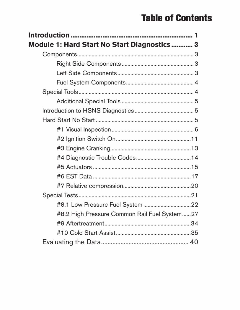
Table of Contents
Introduction...................................................................... 1Module.1:.Hard.Start.No.Start.Diagnostics............. 3
Components ................................................................................. 3
Right Side Components .................................................. 3
Left Side Components ..................................................... 3
Fuel System Components ............................................... 4
Special Tools ................................................................................ 4
Additional Special Tools .................................................. 5
Introduction to HSNS Diagnostics ......................................... 5
Hard Start No Start .................................................................... 5
#1 Visual Inspection ......................................................... 6
#2 Ignition Switch On ....................................................11
#3 Engine Cranking .......................................................13
#4 Diagnostic Trouble Codes ......................................14
#5 Actuators ....................................................................15
#6 EST Data ....................................................................17
#7 Relative compression ...............................................20
Special Tests ..............................................................................21
#8.1 Low Pressure Fuel System ................................22
#8.2 High Pressure Common Rail Fuel System ......27
#9 Aftertreatment ............................................................34
#10 Cold Start Assist ....................................................35
Evaluating the Data ...................................................... 40


Introduction
Welcome to the 2008 International® MaxxForceTM 11 and MaxxForce™ 13 Engine Diagnostics Web Based Training Course. This is the second of two web-based training programs covering theMaxxForce 11 and MaxxForce 13. This program will cover Hard Start No Start Diagnostics and Performance Diagnostics.
To receive credit for completing this training course, you must take a post test on ISIS®/Education/Service/Online Testing.
Introduction 1
Objectives
Upon.Completion.of.this.program,.you.will.be.able.to:
Identify.the.tests.of.the.Hard.Start.No.Start.process.
Identify.possible.causes.of.Hard.Start.No.Start.conditions.
Identify.the.steps.of.the.low.Fuel.Pressure.Diagnostics.
Identify.the.special.tools.required.for.each.step.of.low.Fuel.Pressure.Diagnostics.
Identify.the.steps.of.the.low.Fuel.Rail.Pressure.Diagnostics.
Identify.the.special.tools.required.for.each.step.of.low.Fuel.Rail.Pressure.Diagnostics.
Identify.the.steps.of.the.Cold.Start.Assist.system.diagnostics
•
•
•
•
•
•
•

NOTES
2 2007 MaxxForce® 11 and MaxxForce® 13 Engine Diagnostics
Module 1: Hard Start No Start Diagnostics 3
Hard Start No Start Diagnostics
Components
The components discussed in this section of the course are listed below.
Right Side Components
EGR Valve ActuatorHP-CACLP-CACRetarder Actuator
Left Side Components
AFT Cut-Off ValveCKP SensorCMP SensorCSA Glow PlugCSA RelayECMEIMFuel Filter ModuleHigh Pressure PumpITVMAP/IAT2
••••
•••••••••••
Module 1
Objectives
Upon.Completion.of.this.topic,.you.will.be.able.to:
Identify.the.tests.of.the.Hard.Start.No.Start.process.
Identify.possible.causes.of.Hard.Start.No.Start.conditions.
Identify.the.steps.of.the.low.Fuel.Pressure.Diagnostics.
Identify.the.special.tools.required.for.each.step.of.low.Fuel.Pressure.Diagnostics.
Identify.the.steps.of.the.low.Fuel.Rail.Pressure.Diagnostics.
Identify.the.special.tools.required.for.each.step.of.low.Fuel.Rail.Pressure.Diagnostics.
Identify.the.steps.of.the.Cold.Start.Assist.system.diagnostics
•
•
•
•
•
•
•
4 2007 MaxxForce® 11 and MaxxForce® 13 Engine Diagnostics
Fuel System Components
#6 Injector High Pressure Fuel LineAFT Cut-Off Valve Pressure LineClean Low Fuel Pressure Supply LineCylinder Head Fuel Return LineFuel Strainer Supply LineFuel Supply Pump Suction LineHigh Pressure Pump Fuel InletHigh Pressure Pump Fuel Return LinePLV Return Line Banjo Bolt
Special.Tools
The following special tools are used in the Hard Start No Start procedures described in this section of the program:
ZTSE 4905 Fuel Block Off ToolZTSE 4891 Disposable Air and Fuel CapsZTSE 4906 Fuel Fitting AdapterZTSE 4886 Fuel Inlet Restriction and Aeration ToolZTSE 4887-1 High Pressure Return Line Tester - 17 mmZTSE 4887-2 High Pressure Return Line Tester - 19 mm
•••••••••
••
••
•
•
Module 1: Hard Start No Start Diagnostics 5
Additional Special Tools
ZTSE 4900 High Pressure Rail PlugsZTSE 4681 Fuel Pressure GaugeZTSE 4909 Gauge Bar ToolZTSE 4575 AMP ClampZTSE 4828 Cam and Crank Breakout HarnessZTSE 4773 Fuel Line Disconnecting Tool
Introduction.to.HSNS.Diagnostics
This section shows you the individual steps of the Hard Start No Start diagnostic process. When working on a vehicle that will not start or is hard to start, use this process to direct your work.
Hard.Start.No.Start
Hard Start No Start diagnostics consists of seven required tests and four special tests. You should perform these tests in sequence, unless otherwise stated.
Start with the first seven tests. If you find a problem and correct it, verify that the engine starts properly.
Do not complete the remaining tests if you have found the cause of the No Start.
•••••
•
6 2007 MaxxForce® 11 and MaxxForce® 13 Engine Diagnostics
Perform one or more of the four special tests only if you are directed there by the results of a required test.
#1 Visual Inspection
The first area of the diagnostic form is Visual Inspection. A visual inspection of the engine will allow you to answer the following questions:
Is the engine oil level correct? Is there sufficient clean fuel? Is there a restriction in the intake air system? Is the exhaust system restricted? Are the camshaft and crankshaft position sensors connected? And is there any visible damage to the engine harness?
Is the engine oil level correct?
Check the oil with the vehicle on level ground. The level on the gauge should be between the FULL and ADD lines. If the oil level is low, there could be a problem with oil leaks, oil consumption, or improper servicing. If the oil level is above the ADD mark, there may be a problem with fuel dilution, coolant contamination, or improper servicing.
Although low or high oil level will not directly stop the engine from starting, it may indicate a mechanical problem that requires further investigation.
•••
••
•
“If the oil level is low, there could be a problem with oil leaks, oil consumption, or improper servicing. If the oil level is above the ADD mark, there may be a problem with fuel dilution, coolant contamination, or improper servicing.”
Module 1: Hard Start No Start Diagnostics 7
Possible problems include improper servicing, oil leaks, oil consumption, fuel dilution, and coolant contamination.
Is there enough fuel to start the engine?
Use the dash gauge and/or fuel tank fill port to verify the level in the fuel tank. Then do a visual inspection of the left side of the engine for fuel leaks or damaged fuel lines.
Are there any fuel leaks?
Inspect the following components for fuel leaks: high pressure lines, high pressure pump, low pressure lines, low pressure pump, suction lines, return lines, and the fuel filter module.
Is the fuel contaminated?
Retrieve a fuel sample from the tank and check it for signs of water, waxing, and sediment.
Does the fuel smell like gasoline or kerosene? If the fuel quality is questionable, a clean secondary fuel source may need to be connected to the engine to aid in diagnosing the issue.
Possible problems include water in the fuel, gasoline or kerosene in the fuel, and debris in the fuel.
“If the fuel quality is questionable, a clean secondary fuel source may need to be connected to the engine to aid in diagnosing the issue.”
8 2007 MaxxForce® 11 and MaxxForce® 13 Engine Diagnostics
Is the fuel strainer clean?
Visually check the fuel strainer bowl for sediment and service if necessary.
Open the fuel filter housing drain and take a fuel sample into a clean container. Inspect the sample for debris, icing and contamination. If any fuel issues exist, the fuel filter element may need to be replaced.
Possible problems include improper servicing and fuel contamination.
Is the coolant level correct?
Check the coolant level in the surge tank. Perform a visual inspection of the entire engine area for coolant leaks, including both charge air coolers and the external coolant piping at the rear of the engine.
Possible problems include, improper servicing, external coolant leaks, coolant leak in the EGR cooler, coolant leaking into the cylinders, coolant leak in a charge air cooler, and coolant leak in the aftertreatment injector.
“Perform a visual inspection of the entire engine area for coolant leaks, including both charge air coolers and the external coolant piping at the rear of the engine.”
Module 1: Hard Start No Start Diagnostics 9
Is there a restriction in the intake air system?
Perform a visual inspection of the intake air system for signs of damage, restrictions, and air leaks. Air is required in the cylinders to create the compression needed to ignite the diesel fuel. If air cannot enter the cylinders during cranking, the engine will not start.
Check the restriction gauge on the air filter housing, both charge air coolers, the air inlet duct, the intake throttle valve, and the intake piping to the turbo for signs of damage. Inspect all intake system connections and clamps. If an air induction issue is found, repair as required.
Possible problems include loose or damaged clamps, damaged connectors, restricted air filter, intake throttle valve stuck closed, and an air intake restricted by debris, rags, or plastic bags.
Is there a restriction in the exhaust system?
Perform a visual inspection of the exhaust system for damage that could restrict the flow. If exhaust cannot exit the cylinder, fresh air cannot enter the cylinders, and the engine will not start.
“Check the restriction gauge on the air filter housing, both charge air coolers, the air inlet duct, the intake throttle valve, and the intake piping to the turbo for signs of damage.”
10 2007 MaxxForce® 11 and MaxxForce® 13 Engine Diagnostics
Possible problems include, damaged exhaust pipes, aftertreatment system regeneration required, restricted aftertreatment system, and the retarder butterfly stuck closed.
Are the camshaft and crankshaft position sensors connected?
Check the engine and chassis harnesses for signs of damage. Verify the camshaft and crankshaft position sensors are connected. The engine can start with only one sensor working but the crank time will be longer. The engine cannot start with both sensors disconnected or failed.
Possible problems include damaged harnesses and disconnected cam and crank position sensors.
“The engine can start with only one sensor working but the crank time will be longer. The engine cannot start with both sensors disconnected or failed.”
Module 1: Hard Start No Start Diagnostics 11
#2 Ignition Switch On
The ECM and EIM must have power and ground for the engine to start. The third module, the aftertreatment control module (ACM), should be powered up with the ignition switch-On, but is not required to start the engine. The ignition switch-On test has you answer the following questions:
Is the ECM powered up?Is the EIM powered up?Does the ECM and EIM stay powered up during cranking?
Are the engine control modules powered up?
Step 1 of 3
A quick test of the module’s power is to check if the EST will display either the EIM and ECM calibrations or sensor values from both modules. To perform this test follow the steps below.
First, start the engine by turning the ignition key.
Second, click the Connect button in the upper left of the SA_MD screen.
Step 2 of 3
Next, click the Launch EST button in the lower right corner after the EST connects to the ECM and engine data is displayed.
•••
“A quick test of the module’s power is to check if the EST will display either the EIM and ECM calibrations or sensor values from both modules.”
12 2007 MaxxForce® 11 and MaxxForce® 13 Engine Diagnostics
Step 3 of 3
Finally, click the VIN+ button to start the VIN+ session.
Look for the ECM calibration, EIM calibration, Inlet Air Temp, and the Coolant Temp values.
Are both the ECM and EIM displaying data?
If the module calibrations or the sensor data from both the EIM and the ECM are displayed, the EIM and ECM have power. If the calibrations and the sensor data are not displayed, one or both modules may not be powered up.
Are the ECM and EIM powered up while cranking?
Verify both ECM and EIM stay in communication with the EST while cranking. If the ECM and EIM calibrations were not displayed during cranking, the starter load on the batteries may have caused the battery voltage to fall below the required level.
“If the module calibrations or the sensor data from both the EIM and the ECM are displayed, the EIM and ECM have power. If the calibrations and the sensor data are not displayed, one or both modules may not be powered up.”
Module 1: Hard Start No Start Diagnostics 13
Are the fuses, breakers, and relays okay?
If you suspect that the modules are not powered up, check the fuses, breakers, and relays for the ECM and EIM. The cover to the power distribution panel has a diagram of the fuse, circuit breaker, and relay locations. If necessary, consult the ECM and EIM PWR section of Electronic Control System Diagnostics in the diagnostic manual on ISIS to diagnose the problem.
Possible Problems include no Key power (V-ign) to the modules, failed EIM relay, poor EIM and/or ECM grounds, EIM or ECM failure, damaged harness, corroded or blown fuses or breakers, both cam and crank position sensors failed, and engine CAN line failure.
#3 Engine Cranking
Cranking RPM must be high enough for the high pressure fuel pump to build the correct pressure and for the compression in the cylinders to create the heat required to ignite the fuel.
“Cranking RPM must be high enough for the high pressure fuel pump to build the correct pressure and for the compression in the cylinders to create the heat required to ignite the fuel.”
14 2007 MaxxForce® 11 and MaxxForce® 13 Engine Diagnostics
The Engine Cranking Test has you answer the following questions:
Does the engine cranking speed meet the specification?Does the engine have sufficient oil pressure?
Is the cranking speed sufficient to start the engine?
Check the cranking speed on the instrument panel Tach or the EST. If engine speed is below the minimum cranking speed, the engine will not start. Check the instrument panel oil pressure gauge. Does the engine have oil pressure while cranking?
Possible problems include loose or corroded battery connections, low or no battery power, cylinder hydraulic or mechanical lock, starter motor problem, and incorrect oil viscosity for climate.
#4 Diagnostic Trouble Codes
Checking for diagnostics trouble codes will let you answer the following question:
Are there any DTCs that indicate a failure in any of the following systems: electrical, high pressure fuel system, air management system, fuel supply system, aftertreatment system, or the cold start assist system?
•
•
•
“Check the cranking speed on the instrument panel Tach or the EST. If engine speed is below the minimum cranking speed, the engine will not start.”
Module 1: Hard Start No Start Diagnostics 15
Are there active diagnostic trouble codes?
Use the EST to check for diagnostic trouble codes that would effect the engine starting.
When working on a vehicle, record all the DTCs onto the diagnostic form. If there are unknown codes, record the SPN and the FMI. Correct the cause of the active codes before continuing to the next test. Then clear the codes.
Possible problems include EIM or ECM failure, high pressure fuel system failure, air management system failure, fuel supply system failure, aftertreatment system failure, cold start assist system failure, and Intake throttle valve failure.
#5 Actuators
Three of the actuators that must work properly for the engine to start are the EGR actuator, the retarder actuator, and the inlet throttle valve.
“Three of the actuators that must work properly for the engine to start are the EGR actuator, the retarder actuator, and the inlet throttle valve.”
16 2007 MaxxForce® 11 and MaxxForce® 13 Engine Diagnostics
Performing the Actuator test allows you to answer the following questions:
Is the EGR valve closed?Is the retarder flap open?Is the inlet throttle open?
Are the engine actuators working correctly?
The three engine actuators must be in the proper position during cranking.
Both the EGR and Retarder actuators must be in the correct position for starting.
The inlet throttle valve can be checked by placing your hand on the valve during the test and feeling the movement of the flap. It will open and close several times during the Actuator test. If the valve is suspect, remove the valve and check for free movement of the shaft.
Performing the Actuator Test
Start the Actuator test by completing the following steps on the EST screen. First, click the Session icon to open the Sessions menu. Second, click D_Actuator.ssn to open the actuator session. Third, click Diagnostics on the menu bar. Fourth, use your mouse to
•••
“The three engine actuators must be in the proper position during cranking.”
Module 1: Hard Start No Start Diagnostics 17
hover the cursor over Diagnostics on the drop down menu. Finally, click on Actuator Test.
During the test, the ECM will command each of the engine actuators one at a time. Each of these actuators will be actuated once for 3-4 seconds.
Verify the operation of the EGR valve actuator, the inlet throttle valve, and the retarder actuator during the test.
If the ambient conditions are correct for the operation of the CSA system, or the system is suspected of causing the starting condition, go to test #10 on the diagnostic form.
Possible problems include a failed actuator, stuck retarder flap, stuck ITV, insufficient vehicle air pressure and electrical component or circuit failure.
#6 EST Data
Reviewing the EST data during cranking will allow you to answer the following questions:
Is the exhaust back pressure high?Is the ECM voltage low?Is the cranking speed correct?Is the EGR valve open?Is the inlet throttle valve closed?
•••••
“During the test, the ECM will command each of the engine actuators one at a time. Each of these actuators will be actuated once for 3-4 seconds.”
18 2007 MaxxForce® 11 and MaxxForce® 13 Engine Diagnostics
Is the FRP low?Is fuel supply pressure low?
Are the engine systems operating correctly?
Use the EST to check the engine systems parameters during cranking.
First, click on the session icon. Second, Click on the D_HardStart_NoStart.ssn. Third, turn the ignition key to crank the engine for twenty seconds.
Why do we look at the following values?
Engine.Speed
If the engine cranking speed is below the minimum, the engine will not start.
Fuel.Rail.Pressure
There is a minimum rail pressure that must be met for the ECM to activate the injectors.
If a fuel system PID value is out of specification when cranking, you would refer to the appropriate Special Test on the HSNS form.
••
“If the engine cranking speed is below the minimum, the engine will not start.”
Module 1: Hard Start No Start Diagnostics 19
Fuel.Pressure.Control.Percentage
The ECM has a cranking value that should be sent to the FPCV on the high pressure pump.
EGRV.Position
The EGR valve should be closed during cranking or the engine will inhale exhaust instead of fresh air.
EGRV.Desired
The ECM should command the EGR valve closed during cranking.
Engine.Fuel.Pressure
If the EFP is low, the engine may not be receiving the right amount of fuel.
ITV.Position
The intake throttle valve must be open. If the ITV is closed the engine will not be able to draw in fresh air.
Fuel.Rate
The fuel rate shows if the ECM is commanding the injectors.
“The fuel rate shows if the ECM is commanding the injectors.”
20 2007 MaxxForce® 11 and MaxxForce® 13 Engine Diagnostics
Battery.Volts.ECM
The ECM must have the proper voltage for the engine to start.
Battery.Volts.EIM
The EIM must have the proper voltage for the engine to start.
Exhaust.Gas.Differential.Pressure
The EGDP sensor measures the restriction through the DPF. If the DPF is heavily restricted the engine cannot be expected to start.
Refer to the Diagnostic Manual on ISIS if the other PIDs are out of cranking specification.
#7 Relative compression
Low cylinder compression can cause the engine to be hard to start or to not start. The relative compression test will tell you if each cylinder of the engine has good compression.
Does each cylinder of the engine have good compression?
Use the EST to start the relative compression test.
Note: Make sure the batteries are fully charged before running the test.
“Low cylinder compression can cause the engine to be hard to start or to not start.”
Module 1: Hard Start No Start Diagnostics 21
First, click Diagnostics on the menu bar. Second, click on IBB Relative Compression Test. Third, follow the instructions on the lower edge of the Relative Compression Diagnostics window for the cranking procedures.
Reading the Text View Data
If one cylinder is significantly higher in value than the others, the cylinder is suspect for compression loss.
If the values displayed here are all approximately equal, compression is okay.
Reading the Graph View Data
The graph displays each cylinder as a vertical bar. If the bars are all about equal in height, the cylinders are equal in compression.
Possible problems include valve train damage, valves out of adjustment, worn or broken piston rings, excessive cylinder wear, and a damaged piston.
Special.Tests
The next four tests are special tests and are only completed when working on a vehicle if you are directed there by one of the seven required tests.
“The graph displays each cylinder as a vertical bar. If the bars are all about equal in height, the cylinders are equal in compression.”
22 2007 MaxxForce® 11 and MaxxForce® 13 Engine Diagnostics
#8.1 Low Pressure Fuel System
There are five possible causes of low pressure at the EFP sensor. The Low Pressure Fuel System tests will let you answer the following questions:
Is there a restriction on the suction side of the system? Has the supply pump failed? Has the sensor or sensor circuit failed? Is there an air leak on the suction side of the system? Is there a fuel leak on the pressure side of the system?
Why does the EST display low fuel pressure?
There are seven steps to detect the cause of low pressure. They are visual inspection, measure inlet restriction, finding a restriction on the suction side, verifying the sensor and circuit, checking for flow and aeration, finding the cause of aeration, and dead-heading the supply pump. Step 1: Visual Inspection, was completed earlier in the Hard Start No Start Process
•
••
•
•
Module 1: Hard Start No Start Diagnostics 23
Step 2: Is inlet restriction within specifications?
Connect a 0-30 in-Hg vacuum gauge to the test fitting on the fuel primer pump. Then crank the engine for 20 seconds.
If the restriction is within specification when performing this test, move to step four.
Step 3: Is the strainer clean?
Remove the fuel strainer. Clean both the bowl and the element and replace the element of any remote mounted pre-filters.
Step 4: Was the strainer the problem?
Retest inlet restriction after the strainer and remote filter have been serviced.Then crank the engine for 20 seconds.
Record the highest reading that occurs while cranking. The restriction should be less than 7 in-hg.
If the restriction is greater than 7 in-Hg when performing this test, there is a blockage between the tank and the fitting. Repair as required.
“If the restriction is greater than 7 in-Hg when performing this test, there is a blockage between the tank and the fitting. Repair as required.”
24 2007 MaxxForce® 11 and MaxxForce® 13 Engine Diagnostics
If the inlet restriction is now within specification, check the fuel pressure on the EST. If the cranking pressure meets the specification, the problem was the strainer or remote element.
Step 5: Is the EFP sensor value correct?
Remove the EFP sensor and adapt a 0-160 psi fuel pressure gauge equipped with a sample hose and valve to the fuel filter housing. You can check the sensor and circuit by comparing the EST reading to a measurement with mechanical gauge. Crank the engine for twenty seconds.
Record the fuel pressure from both the gauge and the EST.
If the pressure meets the cranking specification with the gauge but not the EST, use the Electronic Control System Diagnostics section of the Diagnostics Manual on ISIS to check the sensor and the circuit.
If the pressure is below the specification, move to Step Six to check for aeration.
Step 6: Is the fuel aerated?
Place the sample hose into a clean container and click on the valve lever to
“If the pressure meets the cranking specification with the gauge but not the EST, use the Electronic Control System Diagnostics section of the Diagnostics Manual on ISIS to check the sensor and the circuit.”
Module 1: Hard Start No Start Diagnostics 25
open the valve on the gauge assembly. Crank the engine for twenty seconds.
Watch the flow of fuel from the hose while the engine is cranking.
If there is no flow or the fuel is aerated, go to Test #7, Finding the Cause of Aeration.
If there is no aeration and there is a steady flow of fuel, go to Test #8, Dead-head the Pump.
“If there is no aeration and there is a steady flow of fuel, go to Test #8, Dead-head the Pump.”
26 2007 MaxxForce® 11 and MaxxForce® 13 Engine Diagnostics
Step 7: Finding the Cause of Aeration
Remove the fuel line from the strainer to the supply pump and disconnect the fuel line from the suction side of the strainer housing.
Install the Inlet Restriction/Aeration Hose ZTSE4886 between the strainer and the pump inlet. Using a fuel line connector, connect a clean fuel source to the suction side of the strainer housing. Crank the engine for twenty seconds.
Watch the flow of fuel from the hose while the engine is cranking.
If the aeration problem is fixed, inspect the fuel lines from the strainer inlet to the tank for air leaks.
If the problem still exists, inspect the strainer bowl and housing.
Step 8: Dead-head the Pump
If the fuel pressure is still low after completing Steps 1-7, remove the fuel line from the inlet fitting of the high-pressure pump and install the fuel block-off tool ZTSE4905 into the end of the fuel line.
Crank the engine for twenty seconds.
“If the aeration problem is fixed, inspect the fuel lines from the strainer inlet to the tank for air leaks.”
Module 1: Hard Start No Start Diagnostics 27
Monitor the fuel pressure while the engine is cranking.
If the fuel pressure does not meet the cranking specification, the supply pump is at fault.
If the fuel pressure meets specification, the high pressure fuel system may have a large leak. Perform the high pressure fuel system diagnostics.
#8.2 High Pressure Common Rail Fuel System
There are eight possible causes of low fuel rail pressure. The High Pressure Common Rail Fuel System tests let you answer the following questions:
Is the fuel rail pressure sensor or sensor circuit biased?Is the pressure limiting valve leaking?Is there a leaking pressure pipe or failed injector?Is there a fault in the ECM or fuel pressure control valve circuit?Has the fuel pressure control valve failed?Is the pump return restricted?Is there low fuel supply pressure?Has the high pressure pump failed?
•
••
•
•
•••
“If the fuel pressure does not meet the cranking specification, the supply pump is at fault.”

28 2007 MaxxForce® 11 and MaxxForce® 13 Engine Diagnostics
WARNING: To prevent personal injury or death, use extreme caution when working around high pressure fuel. Make sure that the high pressure fuel pressure system has depressurized before opening any high pressure line or fitting. Use SA-MD to monitor the fuel rail pressure or, if an EST is not available, wait five minutes after the engine stops before opening any fuel lines.
CAUTION: Allowing dirt or debris to enter the clean side of the low pressure fuel system can damage the high pressure pump.
Step #1: Does the fuel supply pressure meet the cranking specification?
Remove the fuel supply line from the inlet side of the AFT cut-off valve. Use the hose fitting ZTSE4906 to connect the restriction/aeration hose tool ZTSE 4886 to the fuel supply line. Use block-off tool ZTSE4905 to plug the open end of the restriction/aeration tool. Attach the fuel pressure gauge to the hose assembly. Crank the engine for twenty seconds.
Monitor the fuel pressure while cranking.
“CAUTION: Allowing dirt or debris to enter the clean side of the low pressure fuel system can damage the high pressure pump.”
Module 1: Hard Start No Start Diagnostics 29
If the fuel pressure does not meet the cranking specification, replace the fuel filter, and perform low fuel pressure diagnostics if required.
If the cranking pressure meets the specifications, move to the next step.
Step #2: Is the ECM signal to the FPCV correct?
Disconnect the engine harness from the FPCV. Install the breakout harness ZTSE4828 between the control valve and the engine harness.
Crank the engine.
Measure the duty cycle while cranking and record the measurement on the form.
If the duty cycle is within specification, return the system to operational condition and proceed to the next step.
If the duty cycle was not within specifications when performing this test, see FPCV in the Electronic Control System Diagnostics section of the Diagnostic manual on ISIS to determine the cause of the incorrect duty cycle.
“If the fuel pressure does not meet the cranking specification, replace the fuel filter, and perform low fuel pressure diagnostics if required.”
30 2007 MaxxForce® 11 and MaxxForce® 13 Engine Diagnostics
Step #3: Does the fuel return line pressure exceed the specification?
Remove the fuel return line from the high-pressure pump. Use the Fuel Fitting Adapter ZTSE4905 to connect the Restriction/Aeration Tool ZTSE4886 between the high pressure pump fuel return line and the return fitting on the high pressure pump. Connect a 160 psi fuel pressure gauge to the quick coupler on the Restriction/Aeration Tool. Crank the engine for twenty seconds
Record the measurement on the form and return the system to operational condition.
If the gauge reading is greater than 3 psi, there is a restriction in the return line to the fuel tank. Repair and retest.
If the reading is below 3 psi, proceed to the next step.
“If the gauge reading is greater than 3 psi there is a restriction in the return line to the to the fuel tank. Repair and retest.”

Module 1: Hard Start No Start Diagnostics 31
Step #4: Is the FRP sensor biased?
Disconnect the engine harness from the FRP sensor.
Now try to start the engine.
If the engine starts, the FRP sensor is biased and must be replaced. Repair and retest.
If the engine does not start, continue to the next step.
Step #5: Is there fuel leaking at the PLV?
Remove the banjo bolt from the PLV return line fitting and install the High Pressure Return Line Tester ZTSE4887-1 using the old banjo bolt sealing washers for the test.
Place the end of the hose into a clean bucket.
Note: The banjo bolt seals must be replaced when this diagnostic step is completed.
Crank the engine for twenty seconds while watching for fuel coming from the hose.
“If the engine starts, the FRP sensor is biased and must be replaced. Repair and retest.”
32 2007 MaxxForce® 11 and MaxxForce® 13 Engine Diagnostics
If more than a few drops of fuel come out of the hose while cranking, the PLV is leaking. Replace the valve and retest.
If no fuel comes out of the high-pressure rail, return the system to operational condition and continue to the next step.
Step #6: Is there excessive return fuel from the cylinder head?
Measure the quantity of fuel that comes from the cylinder head during the time that the engine is cranking. One mililiter of fuel per second should come out of the cylinder head while cranking.
If the return fuel flow significantly exceeds the 1 ml per second value, leave the hose in place and perform Step #7, Isolating Injectors.
If the fuel flow is normal, return the system to operational condition and continue to Step #8, Install a Fuel Pressure Control Valve.
“If no fuel comes out of the high-pressure rail, return the system to operational condition and continue to the next step.”
Module 1: Hard Start No Start Diagnostics 33
Step #7: Which injector or pipe is leaking?
Remove #6 injector line from the engine. Install test cap ZTSE4900 on the #6 line opening on the fuel rail and torque the cap to line tightening specifications.
Crank the engine for twenty seconds.
Watch the rail pressure on the EST and measuring the quantity of fuel that comes from the cylinder head.
If the return fuel flow is now normal, and the rail pressure is within the cranking specification, the problem has been isolated. Remove the injector and injector pipe, replace both and retest.
If the fuel flow is still above the normal amount, continue to remove lines and install caps until the return fuel flow is normal. When the failed injector and line are located, replace both.
“If the return fuel flow is now normal, and the rail pressure is within the cranking specification, the problem has been isolated. Remove the injector and injector pipe, replace both and retest.”
34 2007 MaxxForce® 11 and MaxxForce® 13 Engine Diagnostics
Step #8 Is the Fuel Pressure Control Valve the cause of the low FRP?
At this point in the test procedures you have eliminated the following items from being the cause of low fuel rail pressure: low supply pressure, failed ECM or FPCV circuit, biased FRP sensor or sensor circuit, restricted pump return, leaking PLV, and leaking injector pipe or failed injector.
The only items that have not been tested are the FPCV for mechanical failure and the high-pressure pump. If you reach this point and have not found the problem, install a fuel pressure control valve and use the EST to measure the fuel rail pressure while cranking the engine. If the pressure meets the cranking specification, the FPCV was the problem. If the pressure is still low, replace the high-pressure pump.
#9 Aftertreatment
The Aftertreatment section of the HSNS diagnostics will allow you to determine if the AFT system restricted.
Is the AFT system restricted?

Module 1: Hard Start No Start Diagnostics 35
Use the EST to find the values of Exhaust Gas Differential Pressure sensor and the Exhaust Back-Pressure sensor while cranking the engine.
If the EGDP value is high for cranking, the DPF may be plugged.
If the EGDP value is normal for cranking but the EBP is high for cranking, the DOC may be plugged.
If both sensor values are correct for cranking, the AFT system is not restricted
Possible causes include high DPF loading, DPF damage, EGDP sensor circuit faults, or sensor failure.
#10 Cold Start Assist
The last area of the diagnostic form is Cold Start Assist. This section will allow you to answer the following questions:
Are the current conditions correct for CSA operation? Is the glow plug getting hot? Is fuel being injected onto the glow plug? Does the glow plug draw the correct amperage? Is the fuel pressure to the glow plug correct?
•
••
•
•
“The last area of the diagnostic form is Cold Start Assist.”

36 2007 MaxxForce® 11 and MaxxForce® 13 Engine Diagnostics
Are the conditions correct for the cold start assist system to operate?
Use the EST to view the engine temperature values. The cold start assist system only operates when specific temperatures are at at 0° C (32° F) or below, or if the vehicle is at an altitude greater than 5,000 feet above sea level. The sensors that the system monitors are: EOT, ECT, ECT2, IAT, or IAT2 (Boost Temp.).
Turn the engine on.
Is the glow plug getting hot?
During System operation, monitor the IAT2 (Boost Temp) value for twenty seconds. If the glow plug temperature is increasing, the IAT2 will sense the heat
If the IAT2 (Boost Temp) value rises, go to the Monitor MAT test.
If the IAT2 (Boost Temp) value does not rise go to the Glow Plug Current Draw test.
“During System operation, monitor the IAT2 (Boost Temp) value for twenty seconds. If the glow plug temperature is increasing, the IAT2 will sense the heat.”
Module 1: Hard Start No Start Diagnostics 37
Is fuel being injected on to the glow plug?
Monitor.MAT
If the IAT2 did rise with the key-On, crank the engine and monitor the MAT sensor value. The MAT value should rise slowly.
If the MAT value does rise, fuel is being injected onto the glow plug.
If the MAT value does not rise, check the fuel pressure to the injector.
Does the glow plug draw the right number of Amps?
Glow.Plug.Current.Draw
Install an Amp-clamp on the wires feeding current to the glow plug. Turn the engine On. Allow the reading to stabilize. Record the reading.
Is the voltage to the Glow Plug correct?
Use a DMM to measure the voltage available at the glow plug connector while the glow plug is energized.
Turn the engine On and record the reading.
“If the IAT2 did rise with the key-On, crank the engine and monitor the MAT sensor value. The MAT value should rise slowly.”
38 2007 MaxxForce® 11 and MaxxForce® 13 Engine Diagnostics
Is the glow plug working correctly?
Now compare the Amp draw and the voltage reading to the specifications.
If the voltage is B+ and the Amp draw is within specifications, the plug is working correctly.
If the voltage is B+ and the Amp draw is low, replace the glow plug.
If the voltage is less than B+ and the amperage is low, see Cold Start system in the Electronic Control System Diagnostics section of the Diagnostic manual on ISIS to diagnose the low voltage.
If the Amp draw is greater than the specification, replace the glow plug.
Is there fuel pressure at the glow plug?
Disconnect the fuel line to the glow plug and attach a fuel pressure gauge.
Crank the engine.
There should be 8 psi of fuel pressure while the engine is cranking.
If the pressure is within specifications the solenoid is working correctly.
“If the voltage is less than B+ and the amperage is low, see Cold Start system in the Electronic Control System Diagnostics section of the Diagnostic manual on ISIS to diagnose the low voltage.”
Module 1: Hard Start No Start Diagnostics 39
If the pressure is low, see Cold Start system in the Electronic Control System Diagnostics section of the Diagnostic manual on ISIS to determine if the solenoid is operating correctly.
Possible causes include a failed CSR, CSR circuit faults, a failed CSS valve, CSS valve circuit faults, and failure of the fuel supply circuit within the fuel filter module.
40 2007 MaxxForce® 11 and MaxxForce® 13 Engine Diagnostics
Evaluating.the.Data
This section of the MaxxForce 11 and MaxxForce 13 Engine Diagnostics has demonstrated the step by step procedures that should be used when diagnosing an engine that is hard to start or will not start.
Following these procedures will allow you to answer these questions and narrow your diagnostic efforts.
Does a visual inspection reveal why the vehicle will not start?Are the engine control modules powered up?Is the cranking RPM high enough?Are there active diagnostic trouble codes?Are the engine actuators working correctly?Are the engine systems working correctly?Does each cylinder have good compression?Does the engine have sufficient EFP?Does the engine have sufficient FRP to start?Is the AFT system restricted?Is the CSA system operating correctly?
•
•
••
•
•
•
•
•
••

NOTES
2007 MaxxForce® 11 and MaxxForce® 13 Engine Diagnostics 41

NOTES
42 2007 MaxxForce® 11 and MaxxForce® 13 Engine Diagnostics

NOTES
2007 MaxxForce® 11 and MaxxForce® 13 Engine Diagnostics 43
