environmental sustainability calibration tool - zendesk · 5.5 ele mr 4 : power factor correction...
TRANSCRIPT


MAS Sustainability Calibration Tool V 1.2
MAS Confidential Page 2
Copyright © 2015 MAS Holdings (Pvt) Ltd
All rights reserved

MAS Sustainability Calibration Tool V 1.2
MAS Confidential Page 3
Contributing Members
Authors Vidhura Ralapanawe MAS Intimates Hashini Wickramarathne MAS Intimates Shahen Amaratunga MAS Corporate Sajeewa Gunasena Linea Aqua Madumantha Kandepola Linea Aqua Hiru Jayathunga MAS Intimates Akvan Gajanayake MAS Intimates Isira Weerarathne Noyon Lanka Stanley Wijesinghe Bodyline Harsha Deraniyagala MAS Fabric Park Nandana Dissanayake MAS Fabric Park Dhanujie Jayapala MAS Corporate Shehani Gomes MAS Active Udara Logus MAS Corporate Ruwan Nilwakka Trischel Kokila Arandara MAS Intimates Thurulie Sampath Ponnamperuma MAS Intimates Unichela
Version 1.2
Sanjaya Jayawardana Bodyline
Chamila Warathenne MAS Active Contourline
Rohitha Nandasena Silueta
Nadeera Wijesinghe Linea Intimo
Kasun Illangasinghe MAS Fabric Park
Vindyani Jayasinghe MAS Active
Janaka Priyadarshana MAS Intimates Unichela
Prageeth Sarasanantham MAS Fabrics
Suneth de Silva MAS Corporate
Technical Advisors Kelum Perera
Compiled by Shahen Amaratunga
Hashini Wickramarathne
Contributions by the MAS Energy Forum are acknowledged, without which this document
would not have been complete.

MAS Sustainability Calibration Tool V 1.2
MAS Confidential Page 4
Table of Revisions
1. SCMR1: Scope defined
2. SCMR2: Scope defined
3. SCMR3: Scope defined
4. SCRA1: Best practices changed to Initiatives. Scope re-defined
5. ELEMR3: Over voltage included under protection & safety
6. ELEMR3: Earthing resistance value included
7. ACMR1: Facilities are exempted from this for version 1.2
8. IEQMR1: Indoor CO2 tolerance range defined
9. WMMR3: PHI report if sufficient for piggeries
10. WMMR3: EPL certification not mandatory for fabric waste

MAS Sustainability Calibration Tool V 1.2
MAS Confidential Page 5
Introduction
The calibration tool was developed to assess, benchmark rate and subsequently improve existing
infrastructure in all MAS Holdings facilities. This document also aims to standardise and replicate
best practices throughout the group while ensuring efficient operations and continuously
improve the environmental sustainability baseline towards a net zero impact facility.
The calibration tool comes in two parts consisting of the guide document and checklist. The guide
document lists out the road map for each facility to achieve the minimum mandatory
requirements henceforth known as MR for the MAS Sustainability benchmark. It also lists out
additional recommended actions henceforth known as RA that a factory can attempt to
implement and achieve a higher rating in the calibration tool. The guide document provides a
detailed description of the areas covered in each section.
The calibration tool checklist is a detailed self-assessment tool that lists both the mandatory as
well as recommended actions required to successfully pass each section of the tool. Each
requirement comes with a list of parameters to fulfil as well as required documents to be
submitted as part of the assessment process.
The calibration tool is separated in to sections and will cover Sustainability Strategy (SS),
Sustainability Culture (SC), Sewing Machines (SM), Lighting (LT), Electrical Systems (ELE),
Compressors (CMP), Air Conditioning (AC), Boilers (BL), Indoor Air Quality (IEQ), Water Efficiency
(WE), Waste Management (WM), Emissions (EM), Building Site & Envelop (STE) & Chemical
Management (CM).
These sections are further sub-divided and the subsections will receive a Mandatory
Requirement or a Recommended Action rating. All mandatory requirements must be completed
by each facility to achieve the baseline score. Facilities that fail to achieve this baseline score will
not be considered. Recommended actions will be awarded points depending on an allocation
weightage.
MAS Sustainability Calibration Tool V 1.2
MAS Confidential Page 6
Table of Contents 1.0 Sustainability Strategy (SS) ..................................................................................................... 10
1.1 SS MR 1 : Long Term Sustainability Strategy ...................................................................... 10
1.2 SS MR 2 : Annual Sustainability Plan .................................................................................. 10
1.3 SS MR 3 : Sustainability KPI Review .................................................................................... 11
1.4 SS MR 4 : Plant sustainability team .................................................................................... 11
1.5 SS MR 5 : Sustainability Awareness for Management ....................................................... 12
1.6 SS MR 6 : Use of Eco Tracker .............................................................................................. 12
1.7 SS MR 7 : Certification ........................................................................................................ 12
1.8 SS RA 1 : Renewable Energy .............................................................................................. 12
2.0 Environmental Sustainability Culture (SC) ............................................................................. 13
2.1 SC MR 1 : Events & Initiatives ............................................................................................. 13
2.2 SC RA 1 : Initiatives ............................................................................................................. 14
2.3 SC MR 2 : Employee Engagement ...................................................................................... 14
2.4 SC MR 3 : Community Engagement.................................................................................... 15
2.5 SC RA 2 : Innovation & Lean ............................................................................................... 15
2.6 SC RA 3 : Training................................................................................................................ 15
3.0 Sewing Machines (SM) ........................................................................................................... 16
3.1 SM MR 1 : Energy Efficient Motors .................................................................................... 16
3.2 SM RA 1 : Direct Drive Motors For New Machines ........................................................... 17
3.3 SM RA 2 : Best Practices ..................................................................................................... 17
3.4 SM RA 3 : On-demand controls for compressed air ........................................................... 18
4.0 Lighting (LT) ............................................................................................................................ 19
4.1: LT MR 1 : Minimum Illuminance level ............................................................................... 19
4.2: LT RA 1 : Lighting power density ....................................................................................... 20
4.3 LT RA 2 : Lighting Controls .................................................................................................. 20
4.4 LT RA 3 : Lamps & Lamp Fittings ........................................................................................ 21
4.5 LT RA 4 : Day lighting .......................................................................................................... 22
5.0 Electrical Systems (ELE) .......................................................................................................... 23
5.1 ELE MR 1 : Mains Metering ................................................................................................ 23
5.2 ELE RA 1 : Sub-Systems Metering ....................................................................................... 23
5.3 ELE MR 2 : Electrical Drawings ........................................................................................... 23
5.4 ELE MR 3 : Protections & safety ......................................................................................... 24
5.5 ELE MR 4 : Power Factor Correction ................................................................................. 25

MAS Sustainability Calibration Tool V 1.2
MAS Confidential Page 7
5.6 ELE RA 2 : Load scheduling ................................................................................................. 25
5.7 ELE MR 5 : Testing .............................................................................................................. 25
5.8 ELE RA 3 : EMS Connectivity ............................................................................................... 26
6.0 Compressed Air (CMP) ........................................................................................................... 27
6.1 CMP MR 1 : Calculate Compressor Sizing ........................................................................... 27
6.2 CMP MR 2 : Plant Room Design ......................................................................................... 33
6.3.1 CMP MR 3 : Air Quality Parameters ............................................................................... 35
6.3.2 CMP MR 4 : Refrigerants ................................................................................................. 36
6.4.1 CMP RA 1 : Piping Material ............................................................................................. 37
6.4.2 CMP RA 2 : Distribution System Pressure Management ................................................. 37
6.5.1 CMP MR 5 : Standard Operating Procedure (SOP) .......................................................... 39
6.5.2 CMP RA 3 : Policies .......................................................................................................... 39
6.5.3 CMP MR 6 : Maintenance Schedule ................................................................................ 40
6.5.4 CMP MR 7 : leak detection and prevention program ..................................................... 41
6.6 CMP MR 8 : Health and Safety ........................................................................................... 43
6.7 CMP RA 4 : Training ............................................................................................................ 43
7.0 Air Conditioning (AC) .............................................................................................................. 44
7.1 AC MR 1 : Actual Heat Load ................................................................................................ 44
7.2 AC MR 2 : List of AC Equipment ......................................................................................... 44
7.3 AC RA 1 : Efficiency Calculation .......................................................................................... 45
7.4 AC MR 3 : Standard Operating Procedures (SOP) .............................................................. 46
7.5 AC MR 4 : Preventative Maintenance ................................................................................ 48
7.6 AC MR 5 : Water Treatment ............................................................................................... 51
7.7 AC MR 6 : Training .............................................................................................................. 51
7.8 AC RA 2 : Best Practices ...................................................................................................... 52
8.0 Boilers (BL) .............................................................................................................................. 54
8.1 BL MR 1 : Feed water Quality ............................................................................................. 54
8.2 BL MR 2 : Standard Operating Procedures (SOP) ............................................................... 55
8.3 BL MR 3 : Maintenance Schedule ....................................................................................... 57
8.4 BL MR 4 : Safety Systems ................................................................................................... 58
8.5 BL MR 5 : Operator Training ............................................................................................... 59
8.6 BL RA 1 : Heat recovery & Energy optimising..................................................................... 60
8.7 BL RA 2 : Operational Improvements ................................................................................. 61
9.0 Indoor Environment Quality (IEQ) .......................................................................................... 65
MAS Sustainability Calibration Tool V 1.2
MAS Confidential Page 8
9.1.2 IEQ RA 1 : Permanently Installed CO2 Sensors ................................................................ 65
9.1.3 IEQ RA 2 : Automated System For Fresh Air Management ............................................. 66
9.2.1 IEQ RA 3 : Environment Monitoring Test ........................................................................ 67
9.2.2 IEQ RA 4 : VOC Emissions Test ........................................................................................ 68
9.3.1 IEQ MR 2 : Indoor smoking .............................................................................................. 68
9.3.2 IEQ RA 5 : Fume Extraction for specialized functions ..................................................... 69
10.0 Water Efficiency (WE) .......................................................................................................... 70
10.1.1 WE MR 1 : Source Metering .......................................................................................... 70
10.1.2 WE MR 2 : Sub Metering ............................................................................................... 71
10.1.3 WE RA 1 : Additional Sub metering ............................................................................... 71
10.1.4 WE MR 3 : Treatment of raw water .............................................................................. 72
10.1.5 WE RA 2 : Sustainable Sourcing ..................................................................................... 73
10.2.1 WE MR 4 : Treating and Testing of Waste Water ......................................................... 73
10.2.2 WE RA 3 : Reuse of Treated Waste Water .................................................................... 74
10.3.1 WE MR 5 : Water Efficient Fittings ................................................................................ 75
10.3.3 WE RA 4 : Rainwater harvesting .................................................................................... 76
10.3.4 WE RA 5 : Process Water Recovery ............................................................................... 77
10.3.6 WE RA 7 : Drip irrigation for landscaping ...................................................................... 77
10.4.1 WE RA 8 : Ground Water Recharge ............................................................................... 78
10.5.1 WE MR 6 : Training of Maintenance Personnel ............................................................ 78
10.5.2 WE MR 7 : Plumbing drawing & water balance calculation .......................................... 78
11.0 Waste Management (WM) .................................................................................................. 79
11.1.1 WM MR 1 : Centralised Waste Storage ..................................................................... 79
11.2.1 WM RA 1 : Source Segregation ................................................................................. 80
11.2.2 WM RA 2 : Colour Code for Easy Identification of Waste Types ............................... 80
11.3.1 WM MR 2 : Waste disposal Methods ........................................................................ 81
11.3.2 WM MR 3 : Selection of Waste Recyclers ................................................................. 81
11.3.3 WM MR 4 : Selection of Waste Collectors ................................................................ 82
11.3.4 WM MR 5 : Agreements with Waste Collectors ........................................................ 82
11.3.5 WM RA 3 : Transportation of Waste ......................................................................... 82
11.4.1 WM MR 6 : Waste Records ....................................................................................... 83
11.4.2 WM MR 7 : Monitoring of Waste Collectors and Recyclers ...................................... 83
11.4.3 WM MR 8 : Scheduled Waste Management License ................................................ 83
11.5.1 WM MR 9 : Waste Reduction Kaizen / project.......................................................... 84

MAS Sustainability Calibration Tool V 1.2
MAS Confidential Page 9
11.5.3 WM RA 4 : Encourage Use of Environmentally Friendly Products ............................ 84
11.6.1 WM MR 10 : Training of Waste Handlers .................................................................. 84
11.7.1. WM MR 11 – Responsibility ..................................................................................... 84
12.0 Emissions Management (EM) ............................................................................................... 85
12.1.2 EM MR 1 : Primary data recording ................................................................................ 86
12.2.1 EM MR 2 : Refrigerants Usage....................................................................................... 88
12.3.1 EM MR 3 : Annual Testing of Flue Gas .......................................................................... 89
12.4 EM RA 1 : Scope 3 Emissions ............................................................................................ 89
12.5 EM RA 2 : Guidelines for Stack Emissions ........................................................................ 90
12.6 EM RA 3 : Emission Reduction Initiatives ......................................................................... 90
12.7 EM RA 4 : Biomass Supply ................................................................................................ 90
12.8 EM RA 5 : Large Scale and Long-Term Supply Partners for Biomass ................................ 91
13.0 Building Site & Envelop (STE) ............................................................................................... 92
13.1 STE RA 1 : Landscape Management Plan ......................................................................... 92
13.2 STE RA 2 : Heat Gain & Thermal Envelop ......................................................................... 93
13.3 STE RA 3 : Asbestos Removal ........................................................................................... 94
13.4 STE RA 4 : Site Maintenance ............................................................................................ 94
14.0 Chemical Management (CM) ............................................................................................... 95
14.1.1 CM MR 1: Chemical Management Team ...................................................................... 95
14.1.2 CM MR 2: Chemical Management Policy ...................................................................... 96
14.1.3 CM RA 1: Chemical Management Plan .......................................................................... 96
14.2.1 CM MR 3: Chemical Inventory....................................................................................... 97
14.2.3 CM RA 2: Additional Information of Dyes/Chemicals ................................................... 98
14.2.5 CM MR 4: Chemical Disposal List .................................................................................. 99
14.3.1 CM RA 3: Positive List .................................................................................................. 100
14.3.2 CM MR 5: Water Testing against the ZDHC 11 Priority Chemical Groups .................. 100
14.3.3 CM RA 4: Action Plan in case of non-compliance ....................................................... 101
14.4 CM MR 6: Chemical Storage, Labelling, Handling and Use ............................................ 102
14.4.7 CM RA 5: Secondary Containment .............................................................................. 103
14.5 CM MR 7: Consumption Monitoring .............................................................................. 103
14.6 CM MR 8: Training .......................................................................................................... 104
14.7 CM MR 9: Chemical Barrel Washing............................................................................... 104
ANNEXURES ............................................................................................................................ 105
MAS Sustainability Calibration Tool V 1.2
MAS Confidential Page 10
SS MR 1
SS MR 2
1.0 Sustainability Strategy (SS)
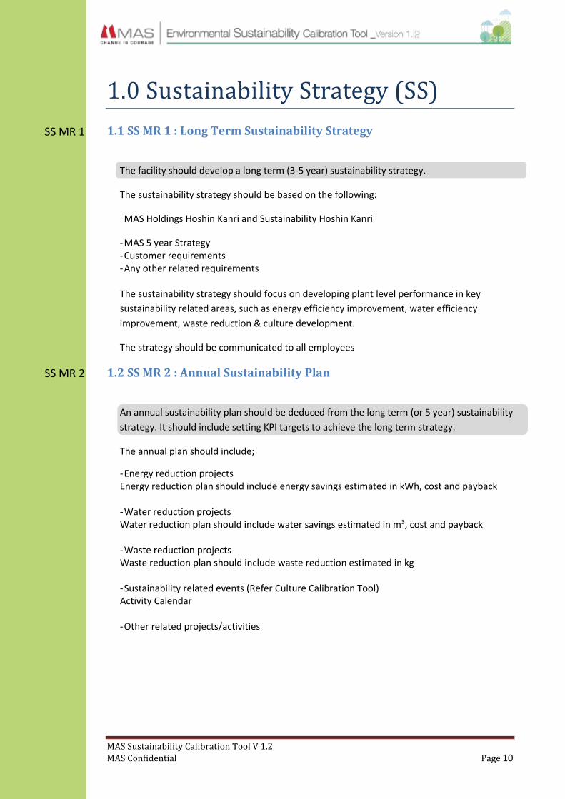
1.1 SS MR 1 : Long Term Sustainability Strategy
The facility should develop a long term (3-5 year) sustainability strategy.
The sustainability strategy should be based on the following:
MAS Holdings Hoshin Kanri and Sustainability Hoshin Kanri
- MAS 5 year Strategy - Customer requirements - Any other related requirements The sustainability strategy should focus on developing plant level performance in key
sustainability related areas, such as energy efficiency improvement, water efficiency
improvement, waste reduction & culture development.
The strategy should be communicated to all employees
1.2 SS MR 2 : Annual Sustainability Plan
An annual sustainability plan should be deduced from the long term (or 5 year) sustainability
strategy. It should include setting KPI targets to achieve the long term strategy.
The annual plan should include;
- Energy reduction projects Energy reduction plan should include energy savings estimated in kWh, cost and payback - Water reduction projects Water reduction plan should include water savings estimated in m3, cost and payback - Waste reduction projects Waste reduction plan should include waste reduction estimated in kg - Sustainability related events (Refer Culture Calibration Tool) Activity Calendar - Other related projects/activities

MAS Sustainability Calibration Tool V 1.2
MAS Confidential Page 11
1.3 SS MR 3 : Sustainability KPI Review
Once the overall long term strategy (MR1), the annual plan (MR2) and KPI’s are determined,
quarterly reviews must be conducted and achievements summarised at year end.
Cluster level sustainability KPIs will be set through the Corporate Sustainability Hoshin and
will be passed down to each facility by the head of each cluster. The facility GM will have
ownership for the KPIs while the Sustainability champion of each facility will be responsible
for achieving them.
Plant sustainability champions will be responsible for achieving the action items spelled out
in the sustainability plan and KPI’s. The targets set in the Hoshin must be achieved by the
facility and will be reviewed quarterly by the central sustainability team.
It is recommended to set department level KPIs where appropriate in order to ensure better
results. (Eg: KPIs at sewing floor and bonding area)
1.4 SS MR 4 : Plant sustainability team
A team should be formed to drive sustainability initiatives of the factory and the KPI’s that
have been set.
Team meetings should be conducted on a quarterly basis and meeting minutes must be
documented.
It is recommended to have a cross functional sustainability team representing all the
departments, including the GM of the plant. The sustainability champion can head this
team.
SS MR 3
SS MR 4

MAS Sustainability Calibration Tool V 1.2
MAS Confidential Page 12
asd
1.5 SS MR 5 : Sustainability Awareness for Management
Awareness sessions for the management must be conducted at least once every year.
These awareness sessions can also include updates on where the facility stands with regard
to the calibration tool and any improvements that need to be done. Some of the
recommended topics to be covered in the awareness programs.
- General awareness on sustainability
- Current trends and developments in the field
- Customer trends
- What MAS is doing
- LEED / ISO14001 certification updates
Senior management of a plant includes all department managers and their deputies.
Awareness to support staff such as cleaning, security is also recommended.
1.6 SS MR 6 : Use of Eco Tracker
Eco tracker data should be updated on a timely and accurate manner. All data should be
updated by the 20th of every month by the responsible person(s).
1.7 SS MR 7 : Certification
Every facility should have a valid Environmental Protection Licence (EPL), ISO 14001:2004
certification and scheduled waste management licence (where required).
This must be obtained for each site separately in the case the facility has multiple sites
(locations). In the case that the facility does not have these, then measures must be taken to
achieve these targets.
1.8 SS RA 1 : Renewable Energy
Facilities should look at options to incorporate on-site or off-site renewable energy and to
be included in the long term strategy of the facility.
SS MR 5
SS MR 6
SS MR 7
SS RA 1
MAS Sustainability Calibration Tool V 1.2
MAS Confidential Page 13
SC MR 1
2.0 Environmental Sustainability Culture (SC)
In order to support the MAS Sustainability Vision it is important that MAS creates a culture of
environmental stewardship. This includes building an employee base who are fully aware of
their roles in a culture of Sustainability and able to take action and support every sustainability
initiative within MAS as well as take the mind-set to their homes. It is also important that MAS
imparts their knowledge and implement initiatives in a wider community to promote an overall
culture of sustainability in a bigger context which would also enhance the image of MAS among
the communities.
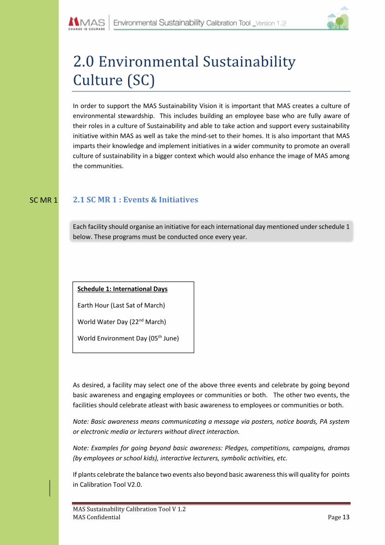
2.1 SC MR 1 : Events & Initiatives
Each facility should organise an initiative for each international day mentioned under schedule 1
below. These programs must be conducted once every year.
As desired, a facility may select one of the above three events and celebrate by going beyond
basic awareness and engaging employees or communities or both. The other two events, the
facilities should celebrate atleast with basic awareness to employees or communities or both.
Note: Basic awareness means communicating a message via posters, notice boards, PA system
or electronic media or lecturers without direct interaction.
Note: Examples for going beyond basic awareness: Pledges, competitions, campaigns, dramas
(by employees or school kids), interactive lecturers, symbolic activities, etc.
If plants celebrate the balance two events also beyond basic awareness this will quality for points
in Calibration Tool V2.0.
Schedule 1: International Days
Earth Hour (Last Sat of March)
World Water Day (22nd March)
World Environment Day (05th June)

MAS Sustainability Calibration Tool V 1.2
MAS Confidential Page 14
SC RA 1
SC MR 2
2.2 SC RA 1 : Initiatives
Conduct 01 new best practice initiative every year on each of energy, water and waste.
Note: Initiative means: internal short term or long-term projects or programmes that are not
Capex projects. These initiatives should aim at reducing plant’s direct impact.
Examples: standardizing switching off lights when leaving a room, switching off AC half an early,
power saving mode for computers, changing dish washing method at the canteen, plastic
reduced zones, food waste reduction programmes, butterfly gardens, ground water recharge,
tree planting and wetland to purify waste water etc.
An initiative can run across multiple themes which still qualifies. For example Plastic Reduced
Zone will qualify as an initiative under energy, water AND waste.
These initiatives can couple with events mentioned in above schedule 1 or separately or with
employee engagement. If a plant does more than one initiative for each theme they will quality
for points in Calibration Tool V2.0.
2.3 SC MR 2 : Employee Engagement
The facility should conduct at least one program that actively engages employees to develop
their understanding on environmental sustainability.
These projects should reach out to more than 20 people and should not be one off projects but
held on a continuous basis. The facility should conduct at least one such program each year or
should have an on-going programme from previous years. For example; Periodic recycling day
programmes, organic home gardening, knowledge sharing such as interactive guest lectures,
periodic competitions, new skill development, awareness building, training etc.
Note: Key is to get people engaged and inspire behavioural change through education and
activities
MAS Sustainability Calibration Tool V 1.2
MAS Confidential Page 15
SC MR 3
SC RA 2
SC RA 3
2.4 SC MR 3 : Community Engagement
The facility should conduct at least one program that actively engages the community to develop
their understanding on environmental sustainability.
These projects should engage more than 20 people and should be long term (more than 6
months) projects. The project could involve any type of community; schools, institutions, villages
etc. The facility should conduct at least one such program each year or should have an on-going
programme from previous years. Example: organic home gardening, clean-up and maintenance
of eco systems, forestry, restoration, waste management, training, awareness building, eco go
beyond projects etc.
Note: Partnerships, education, campaigning, obtaining support, giving support and working
together and inspiring change qualify for engagement.
2.5 SC RA 2 : Innovation & Lean
Innovation: Innovation can be in any areas that will contribute to events, training, knowledge
and awareness, KPIs, products, processes etc.
Lean: Any project done together with or under the guidance of MAS Operating System. The
results of the project should be quantifiable. E.g.: Initiative to reduce fabric waste at source.
2.6 SC RA 3 : Training
It is recommended that relevant employees undergo an external training program related to
environmental sustainability annually.
These programs could include ISO 14001:2004 Lead Auditor, Energy Auditor or Waste Water
Treatment training, etc. This will help develop skills relevant in their job family in the context of
sustainability. The employees sent for training could be in any grade and each year a new person
should be trained.
Training and awareness sessions must be conducted for all Employees.
It is recommended that awareness on environmental sustainability be included in each facility’s
induction or orientation programmes for every level (staff, executives and management)
MAS Sustainability Calibration Tool V 1.2
MAS Confidential Page 16
SM MR 1
3.0 Sewing Machines (SM)
This section will cover the improvements expected to be taken to increase machine efficiency in
order to improve sustainability across the group.
3.1 SM MR 1 : Energy Efficient Motors
All sewing machines in the factory must be fitted with servo motors or direct drive motors by
end 2014. Clutch motors can only be used in situations where the sewing operation of a style
deems it mandatory or effective.
In all servo motors, the control box should be equipped with 24/12 V DC Control outlets.
Progressively replace all clutch motors with servo-motors and use direct drive where it is
applicable
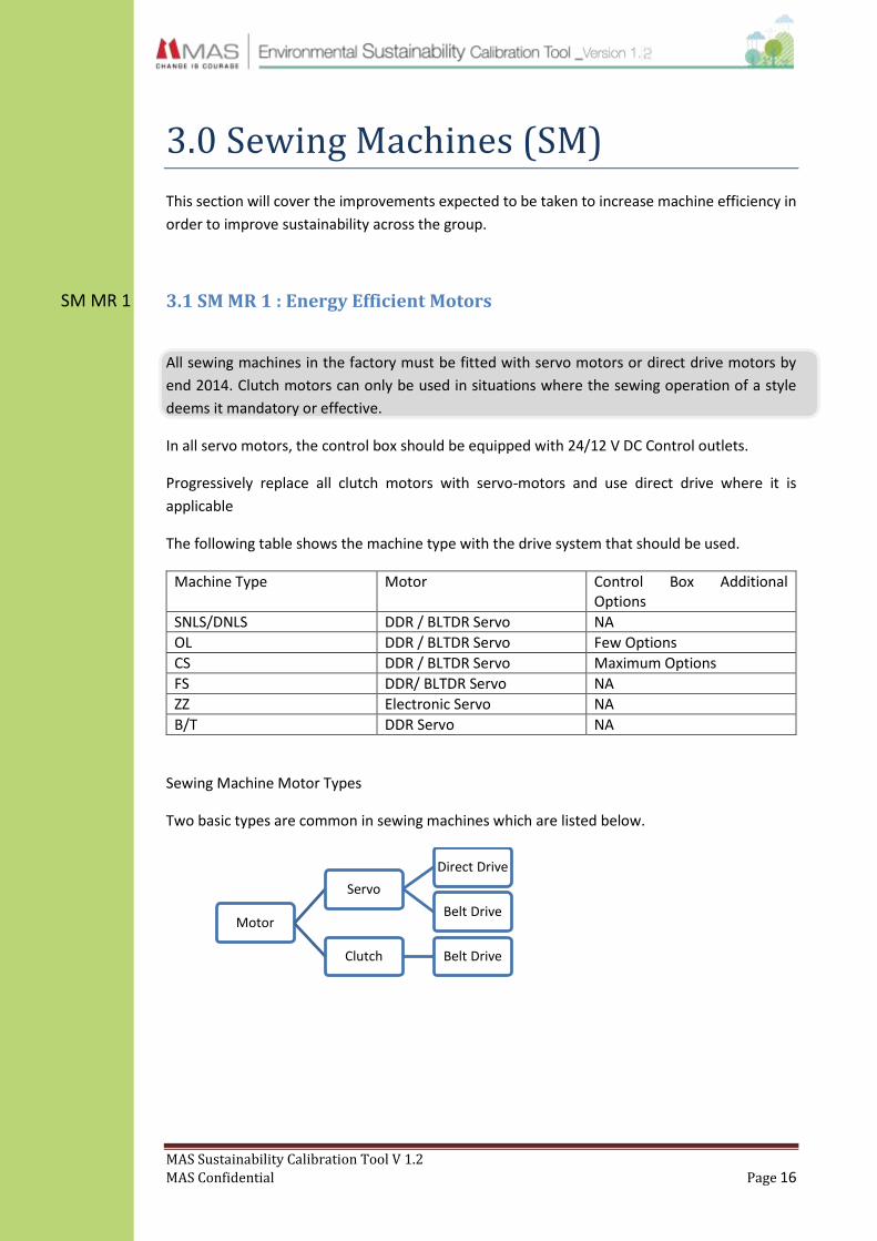
The following table shows the machine type with the drive system that should be used.
Machine Type Motor Control Box Additional Options
SNLS/DNLS DDR / BLTDR Servo NA
OL DDR / BLTDR Servo Few Options
CS DDR / BLTDR Servo Maximum Options
FS DDR/ BLTDR Servo NA
ZZ Electronic Servo NA
B/T DDR Servo NA
Sewing Machine Motor Types
Two basic types are common in sewing machines which are listed below.
Motor
Servo
Direct Drive
Belt Drive
Clutch Belt Drive

MAS Sustainability Calibration Tool V 1.2
MAS Confidential Page 17
SM RA 1
SM RA 2
3.2 SM RA 1 : Direct Drive Motors For New Machines
It is recommended that new sewing machines be installed with direct drive motors.
Direct-Drive Servo motors are preferred than belt drive servos, but where direct drive is not
applicable belt drive can be used.
Consider the motor efficiency parameters as well when purchasing new equipment.
3.3 SM RA 2 : Best Practices
Have in place the best practice initiatives listed below.
Design or modify the electrical grid so that energy consumption of all machinery can be
measured separately through the centralized EMS. Have in place energy sub-metering
to measure this.
If the facility has Building Monitoring System (BMS) software in place, take measures to
connect the machinery to this. Enable remote switching off through BMS.
Training machine operators to switch off machines during break time (tea/lunch).
Design the lighting and machinery grid so that section-wise switching off can be
accommodated.
Ensure that Total Preventive Maintenance (TPM) is effectively carried out.
Categorize motors based on MTBF (mean-time-between-failure)
Equipment
Sustain
Preventive
Maintenance
TBM (Time Based)
CBM ( Condition Based)
Break down
Maintenance
Improvement
Corrective
Maintenace
Prevention of Maintanance

MAS Sustainability Calibration Tool V 1.2
MAS Confidential Page 18
SM RA 3
3.4 SM RA 3 : On-demand controls for compressed air
All sewing machines must use electrically operated solenoids for the foot-lifting operation.
Air lines should be integrated with solenoids and connected to servo motors to control the air
supply.
Uses other than foot lifting must also have on-demand compressed air control systems. No
continuous air output must be given for any operation unless specifically requested.
This will be mandated in the Calibration Tool Version 2

MAS Sustainability Calibration Tool V 1.2
MAS Confidential Page 19
LT MR 1
4.0 Lighting (LT)
4.1: LT MR 1 : Minimum Illuminance level
It is required for each facility to maintain illuminance at the prerequisite levels mentioned
below by measuring the LUX level in each area.
Exceptions are tolerated if customer requirements mention a different LUX level.
Task Type1 Range
Roads and pathways (Outside) General 150 - 300
Workstations Localized 200 - 300
Production Floor General 500
Sewing Needle point Local 900 - 1100
Roads and pathways (Inside) General 200
Walkways (outside) General -
Knitting Localized 1000
Dying General 200
Cutting Localized 1000
Ironing & Spreading General 500
Fabric Inspection Localized 1100
Storage General 500
Precision tasks - Define
Local 2000
Based on ILO compliance requirements
1 Refer appendix C : Lighting system types
MAS Sustainability Calibration Tool V 1.2
MAS Confidential Page 20
LT RA 1
LT RA 2
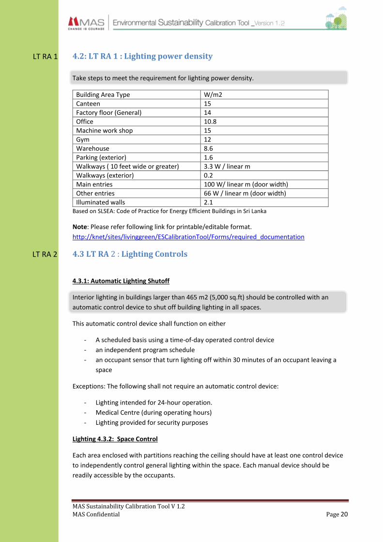
4.2: LT RA 1 : Lighting power density
Take steps to meet the requirement for lighting power density.
Building Area Type W/m2
Canteen 15
Factory floor (General) 14
Office 10.8
Machine work shop 15
Gym 12
Warehouse 8.6
Parking (exterior) 1.6
Walkways ( 10 feet wide or greater) 3.3 W / linear m
Walkways (exterior) 0.2
Main entries 100 W/ linear m (door width)
Other entries 66 W / linear m (door width)
Illuminated walls 2.1 Based on SLSEA: Code of Practice for Energy Efficient Buildings in Sri Lanka
Note: Please refer following link for printable/editable format.
http://knet/sites/livinggreen/ESCalibrationTool/Forms/required_documentation
4.3 LT RA 2 : Lighting Controls
4.3.1: Automatic Lighting Shutoff
Interior lighting in buildings larger than 465 m2 (5,000 sq.ft) should be controlled with an
automatic control device to shut off building lighting in all spaces.
This automatic control device shall function on either
- A scheduled basis using a time-of-day operated control device
- an independent program schedule
- an occupant sensor that turn lighting off within 30 minutes of an occupant leaving a
space
Exceptions: The following shall not require an automatic control device:
- Lighting intended for 24-hour operation.
- Medical Centre (during operating hours)
- Lighting provided for security purposes
Lighting 4.3.2: Space Control
Each area enclosed with partitions reaching the ceiling should have at least one control device
to independently control general lighting within the space. Each manual device should be
readily accessible by the occupants.

MAS Sustainability Calibration Tool V 1.2
MAS Confidential Page 21
LT RA 3
A control device can be provided to turn off lighting within 30 minutes of all occupants leaving
the space. Control devices could be placed in the following areas; meeting rooms, canteen,
wash rooms, individual rooms (managers’ rooms).
Lighting 4.3.3: Exterior Lighting Control.
It is recommended that all exterior (security) lighting application to have automatic controls
capable of turning off exterior lighting when sufficient daylight is available.
These can be controlled by either
- a combination of a photo sensor and a time switch or
- A time switch.
It is recommended that garden lights (decorative purposes) and security light/perimeter lights
are separately controlled. Garden lights can be switched off after 10 pm or can be permanently
switched off if there is no special requirement.
4.4 LT RA 3 : Lamps & Lamp Fittings
It is recommended that incandescent lamps, halogen spot lamps and fluorescent tube lights
with magnetic ballast to be removed from the facility and replaced with more energy
efficient fixtures.
Lighting 4.4.1: Zero usage of Incandescent lamps
It is recommended to remove all the incandescent bulbs from usage.
Exception: Fabric inspection area and other specialized areas are excluded from scope.
Lighting 4.4.2: Zero usage of halogens lamps
It is recommended to remove all the halogen bulbs from usage.
Exception: any lights intended for specific purpose are excluded from scope.

MAS Sustainability Calibration Tool V 1.2
MAS Confidential Page 22
LT RA 4
Lighting 4.4.3: Zero usage of linear fluorescent lights with Magnetic ballasts
It is recommended to remove all magnetic ballasts.
Lighting 4.4.4: Replace fluorescent lights after effective lifetime
It is recommended to replace fluorescent lights after their useful lifetime.
How to identify lights to be replaced
- Flickering
- Black/dark shade developing around two ends (these could be emitting harmful UV
rays)
4.5 LT RA 4 : Day lighting
It is recommended that day lighting options be used for lighting within the facility and that
artificial lighting design be done to incorporate day lighting.
If office areas with day lighting option are available, artificial lighting can be controlled either
manually or automatically.
If skylights are provided for production floors, it is recommended to control artificial lighting
with the day light changes. This will help to maintain necessary illumination levels at the
production floor as well as to optimize savings from the skylight installation.
Lighting 4.5.2: Uniformity of lighting
It is recommended to have uniformity of lighting in order to maintain comfort levels within
occupied spaces.
Note: Uniformity (u) can be obtained by a proper simulation and has to be over 0.5 for the
main production areas.
Lighting 4.5.3: Glare reduction
Use glazing stickers or external shading on windows to reduce glare.
Proper light fixture selection and system design should be considered to reduce glare through
artificial lighting solutions.

MAS Sustainability Calibration Tool V 1.2
MAS Confidential Page 23
ELE MR 1
ELE RA 1
ELE MR 2
5.0 Electrical Systems (ELE)
5.1 ELE MR 1 : Mains Metering
All incoming lines from the utility grid (CEB) and generators should be connected to the Energy
Monitoring System (EMS).
5.2 ELE RA 1 : Sub-Systems Metering
It is recommended to install sub meters to measure energy consumption of additional high
usage components.
The following hierarchy could be followed when considering sub systems for sub metering.
1. AC system
2. Lighting system
3. Machinery system
OR
I. Production units/buildings
II. Office block
III. Compressor
IV. Utilities
5.3 ELE MR 2 : Electrical Drawings
A single line diagram (electrical) must be available with the engineer.
It is recommended to display the drawing in the engineer’s office.
In addition the facility may also have a detailed electrical layout drawing.

MAS Sustainability Calibration Tool V 1.2
MAS Confidential Page 24
ELE MR 3
5.4 ELE MR 3 : Protections & safety
The facility should have appropriate electrical protection and safety devices.
Having considered the purpose for which the installation is being designed, the safety devices
should address the safety of the users, property and the installation.
Type of protection Description
Protection against electric shock Protection against electric shock shall be provided by the application by completely avoiding direct and indirect contact.
Protection against thermal effects
Protection against fire, burns and harmful thermal effects.
Protection against overcurrent Expect where the overcurrent is limited, every live conductor shall be protected by one or more devices for automatic interruption of the supply in the event of overload current and fault current.
Protection against under voltage / over voltage
Suitable precautions shall be taken where a reduction in voltage, or loss and subsequent restoration of voltage, could cause danger.
Isolation and switching Means shall be provided for non-automatic isolation and switching to prevent or remove hazards associated with the electrical installation or electrically powered equipment and machines.
Protection against lightning Good grounding is essential for adequate protection against damage or injury by lightning (earthing resistance should be less than 10 ohms). The protection system needs to get rid of excess energy from the lightning strike by shunting it into the earth.
The above protections can be obtained through the use of MCB, MCCB devices, earth fault
relays/RCCBs, PFR/UVT coil and fuses.
Lightning protection is obtained through lightning conductor (direct) or surge protector
(indirect).
Electrical installation inspection and testing of the total electrical system must be carried out
every three (03) years and signed off by a chartered electrical engineer.
Note: It is recommended that facilities measure the earthing resistance value.10 ohms will be
mandated in version 2.0

MAS Sustainability Calibration Tool V 1.2
MAS Confidential Page 25
ELE MR 4
ELE RA 2
ELE MR 5
5.5 ELE MR 4 : Power Factor Correction
The facility should maintain its power factor at a minimum of 0.98 or better at main feeding
points/main panel room.
It is advisable to use local power factor correction where ever there is a load affecting the total
power factor of the plant. It is also mandatory to conduct routine inspection and maintenance
of the capacitor banks.
It is additionally recommended to maintain the power factor at 0.99
5.6 ELE RA 2 : Load scheduling
Maintain a schedule for switching on sub systems with a high load demand.
The purpose of this is to have the least effect on maximum demand.
The schedule may be made through identifying load pattern demands of the process. Each
schedule must be monitored for consistency on a daily basis.
It is recommended to use automated systems to maintain and monitor equipment within the
facility. Automation should be used to carry out the schedule to optimize the use of electricity
within the facility.
5.7 ELE MR 5 : Testing
The following tests are to be carried out as a part of regular maintenance.
Test Daily Weekly Monthly Biannually Annually
EMS meters inspection (through system) Y
Capacitor banks inspection Y
Lightning protection inspection survey and earthing inspection Y
Surge arrestors inspection Y
Panel boards and wiring terminals inspection Y
MCB / RCCB operation inspection Y
Thermo-graphic survey of electrical sys Y
Electrical test (include safety & earthing) y
Energy audit y

MAS Sustainability Calibration Tool V 1.2
MAS Confidential Page 26
ELE RA 3
Electrical Test must include
Earth test
Main panel switch gear
Insulation level
Protective device operation
Apart from these any other inspections / tests recommended by the manufacturers of the
equipment used within the facility should be carried out as per the provided guidelines.
5.8 ELE RA 3 : EMS Connectivity
The facility should have in place an Energy Monitoring System (EMS).
The EMS can be used to monitor electrical loads connected to the system. The system records
key electrical parameters in 15 minute intervals and data can retrieved through the system
itself. (Please refer attached “EMS Report Generation” document for more information on how
to obtain data). The data can be used to;
Analyze energy use patterns and costs
Identify the impacts of energy saving measures taken by the plants
Provide information to plant management in order to maximize efficiency and to
understand load profiles and hotspots
Identify any anomalies in the system and energy wastage
If any anomalies are found, necessary corrective action must be taken immediately and records
must be maintained. Data should be monitored according to the following frequency in order
to improve energy management within the facility.
Daily Weekly Monthly
Main Incomer Load Profile
Main system load profiles
Sub system load profile
Total energy use
Sectional energy use
Compare CEB and EMS monthly data
It is required to maintain a log for meter locations and connection details for future references.

MAS Sustainability Calibration Tool V 1.2
MAS Confidential Page 27
CMP MR 1
6.0 Compressed Air (CMP)
6.1 CMP MR 1 : Calculate Compressor Sizing
6.1.1 Method 1 – Using Air Flow meter
Use an air flow meter to accurately measure the air intake requirements of all compressed air
usage devices. Tabulate these CFM values to calculate the total system requirement.
Plug in a data logger to the compressor to monitor loading/unloading times, power consumption
and maximum pressure of the compressor.
6.1.2 Method 2 – Hand calculation method
Calculate the total compressed air requirement of the factory in CFM by tabulating the individual
requirement of all equipment as mentioned in its instruction manual.
Compile a list of all machines in the factory based on whether the machines use compressed air.
(E.g. 1)
Example 1: List of machines that use and do not use compressed air.
No Compressed Air Users Compressed Air Non Users
1 Over-lock Single needle
2 Cover-seam / Flat-seam Double needle
3 Hem cutter Zig zag
4 Binding Bar-tag
5 Elasticater
6 Air gun NOTE: Include other types of chain stitch machines, lock stitch machines and specialised machine.
Tabulate the CFM requirements for the machines using compressed air. Two separates tables
are required one for sewing machines and another for specialised non sewing machines. (E.g. 2)

MAS Sustainability Calibration Tool V 1.2
MAS Confidential Page 28
Example 2: List of Sewing Machines
NO Type of Machine No of Machines
CFM per M/C
D factor Total CFM
1 Over-lock machine 1 2.3 0.4 0.92
2 Cover seam machine 1 2.3 0.4 0.92
3 Flat seam machine 1 2.3 0.4 0.92
4 Air gun 1 2.8 0.2 0.56
5 General attachments 1 0.7 1.0 0.70
Tot NOTE: This table could be adjusted when more accurate data is available.
Example 3 : List of specialised machines.
No Type of machine No of Machines
CFM per M/C
D factor Total CFM
1 Cutting table 1 TBC TBC TBC
2 Molding M/C 1 TBC TBC TBC
3 Specialised sewing M/C 1 TBC TBC TBC
Tot
**D Factor – States the actual compressed air usage time in a fraction.
Eg: 0.4 D factor equates that a machine running for 60 seconds will use air for 24 seconds.
TBC – To be calculated
6.1.3 Calculate compressor requirement
Based on the demand analysis carried out, calculate the size of compressor required.
Based on either method 1 or 2 estimate the compressed air volume required for the factory.
Compressors are sized at 8 bar as most sewing machines require air compressed at 6 bar.
Consider pressure drop losses, contingency for future expansions and a safety buffer when sizing
the compressor.
It is recommended to split the air volume requirement and opt for 2 smaller compressors as
opposed to 1 large compressor. The reason being that 1 compressor can run on full load, while
the other can run on part load using a variable speed drive to increase overall efficiency. This
also gives leverage to the production process in the case a compressor fails. The same principle
of having 2 units can be followed for dryer and air receiver as well. All these can be connected to
the same header.

MAS Sustainability Calibration Tool V 1.2
MAS Confidential Page 29
Example 4: Sizing the compressor
Equipment Quantity(nos) Utilization(cfm) D factor
Total(cfm) Full total (cfm)
Overlock 100 2.3 0.4 92
427 Coverseam 100 2.3 0.4 92
Air guns 60 2.8 0.2 33
Specialized Machines
300 0.7 1 210
According to this example the chosen compressor must have FAD of 450cfm considering demand
fluctuation. The most suitable product will be one that can provide this FAD at the lowest
horsepower rating.
6.1.4 Evaluate with current system
Once the ideal compressor sizing has been calculated, it should be compared with the existing
system. Any major deviation between the two systems must be documented and justified.
6.1.5 System Optimisation
It is recommended to have in place as many system optimisations as possible. A few such
methods are given below.
If the current system is over designed or under designed steps must be taken to either introduce
VSD or install new compressors, fulfil short term demand load by installing additional air
receivers closer to the end use location and using multiple smaller compressors to match
different loads/ times/pressures.
Consider the auto condensate drain for compressor, dryer & receiver tank. The temperature at
the air end element of the compressor should be below 100OC, while the temperature at the
dew point of the dryer should be below 7OC.
Paint the compressed air line. Have electronic air controlling solenoids for sewing machines.
Compressor system layout drawing must be available with the engineer.

MAS Sustainability Calibration Tool V 1.2
MAS Confidential Page 30
6.1.6 Calculate Compressor Efficiency (optional)
Efficiency could be calculated using the power output to power input ratio.
𝐸𝑓𝑓𝑖𝑐𝑖𝑒𝑛𝑐𝑦 =𝑉 × 100 × ln (𝑃)
𝑃𝑜𝑤𝑒𝑟
V = Flow rate (L/s)
P = Pressure (bar)
Power = Input power (watt)
This ratio should be compared with the rated efficiency of the compressor and should be
presented in the form of a table.
6.1.7 Calculate size of air receiver tank
The air receiver forms a buffer storage area for the compressed air, balances compressor
pulsations, cools air and collects condensate. The air receiver must be fitted with an automatic
condensate drainage device.
The sizing of the air receiver should follow the following equation.
𝑉𝑅 =𝑄 × 5
𝐴𝐼 × ∆𝑃
VR = Volume of receiver tank (m3)
Q = FAD of compressor (m3/min)
5 = Constant factor
AI = Allowed Motor Cycles
ΔP=Pressure Difference (Cut out pressure – Cut in pressure) (bar)
Table : Figured of constant AI values
Motor power rating (KW) Allowed cycles/h
4-7.5 30
11-22 25
30-55 20
65-90 15
110-160 10
200-250 5
Reference : Compressed air compendium
Note: If 2 or more compressors of different sizing is used chose the lower corresponding AI
value. FAD of variable speed compressor should not be considered when calculating the Q
value. 1 CFM = 0.02831 m3/min.

MAS Sustainability Calibration Tool V 1.2
MAS Confidential Page 31
This equation may also be used; 𝐴𝑖𝑟 𝑅𝑒𝑐𝑒𝑖𝑣𝑒𝑟 𝑆𝑖𝑧𝑒 (𝑚3) = 𝐶𝑜𝑚𝑝𝑟𝑒𝑠𝑠𝑜𝑟 𝐹𝐴𝐷 𝑖𝑛 𝑚3/𝑚𝑖𝑛
3
Air receiver sizes corresponding to compressor type & size;
Modulating Control: 0 to 1 gallon per CFM
On line/ Off line: 3 to 4 gallons per CFM
Stop-start/Variable speed: 4 to 6 gallons per CFM
6.1.8 Calculate the size of the refrigerated air dryer
The compressed air system must be fitted with a refrigerated air drying unit matching the free
air delivery rate of the compressor/s. A contingency factor may be considered for future
expansions. It is also recommended to have an exhaust duct for the dryer unit.
𝐷𝑟𝑦𝑒𝑟 𝑠𝑖𝑧𝑒(𝑐𝑓𝑚)
= 𝐶𝑜𝑚𝑝𝑟𝑒𝑠𝑠𝑜𝑟 𝐹𝐴𝐷 ∗ 𝐼𝑛𝑙𝑒𝑡 𝑎𝑖𝑟 𝑝𝑟𝑒𝑠𝑠𝑢𝑟𝑒 𝐶𝐹 ∗ 𝐼𝑛𝑙𝑒𝑡 𝑎𝑖𝑟 𝑡𝑒𝑚𝑝𝑒𝑟𝑎𝑡𝑢𝑟𝑒 𝐶𝐹
∗ 𝐴𝑚𝑏𝑖𝑒𝑛𝑡 𝑎𝑖𝑟 𝐶𝐹
Refrigerated dryers consume around 3% of total power requirement of a compressor, while
desiccant dryers require 10-25% more power. Therefore refrigeration dryers are recommended,
except in the case where extremely dry air with a low dew point is required.
Manufacturers rate their compressed air dryers in accordance with recommended Standard
CAGI Standard No. ADF100 for 33ºF-39ºF (.5ºC - 3.8ºC) pressure dew point. This is based on 100
psig inlet air pressure, 100ºF (37.7ºC) inlet air temperature, 85ºF (29.4ºC) cooling water
temperature (water cooled units) and 100ºF (37.7ºC) ambient air temperature (air cooled units).
The maximum airside pressure drop allowed is 5 psi.
Inlet air CF / Inlet air temperature CF / Ambient air CF refer to Correction Factors which are
annexed below in ANX CMP B.

MAS Sustainability Calibration Tool V 1.2
MAS Confidential Page 32
6.1.9 Meet best practice filter parameters
Use appropriate filter sizing to adhere to the earlier mentioned air quality standards. It is
mandatory that micro filters (at minimum) are installed in the compressed air system. An
appropriate inlet filter and secondary filter are also required.
Table :
Name Code Description Other Names
Bag filter THNF Cleans dust and contaminated intake air Air filter
Centrifugal separator
ZK Separated accumulating condensate
Eco drain ED Electronic level controlled condensate drain
Pre filter FB/FC Separates aerosol oil and solid particles Line Filter (before dryer)
Micro filter FE/FF Separates aerosol oil and solid particles Line Filter (after dryer)
Activated carbon filter
FG Adsorption of oil vapours
Activated micro FFG Activated carbon and micro filter combination
Activate carbon adsorber
ACT Adsorption of oil vapours
Sterile filter FST For sterile compressed air
Aqua-mat Condensate treatment system
AMCS Air main charging system
Reference : Basic principles, tips, suggestions (Kaeser) / ISO 8573-1
Filter placement example;
(air dryer can be placed before or after the receiver tank)

MAS Sustainability Calibration Tool V 1.2
MAS Confidential Page 33
CMP MR 2 6.2 CMP MR 2 : Plant Room Design
6.2.1 Plant Room Spacing Conditions
All equipment in the compressor room should be arranged taking into consideration minimum
spacing requirements as mentioned in the machine manual, while also considering accessibility
during emergency.
The temperature inside the compressor room should vary by not more than 2O Celsius in
comparison to the outdoor ambient air temperature, measured between 12noon and 2pm on a
warm sunny day, 10 feet away from the plant room air vents. This should be measured on a
quarterly basis. If the location is unable to provide enough fresh air at the recommended
temperature, an air intake fan should be installed to facilitate ventilation, taking care not to
exceed 4m/s air velocity inside the room.
It is recommended that the compressor room be situated in a separate location central to the
plant and designed to promote ventilation without cross-circulation. The compressor should be
preferably placed on a raised platform, plinth or concrete slab foundation. The air intake and the
air exhaust must not be blocked by any permanent or temporary structures.
The compressor room should have a minimum of 1 meter bare space in front and on the sides
with a minimum 6 inches of space at the back, unless otherwise stated in the machine manual.
It is recommended that the compressor room be built to a height of 3m, with wall thickness of
25mm and a well-insulated roof. Direct solar radiation infiltration to the room must be at a
minimum level.

MAS Sustainability Calibration Tool V 1.2
MAS Confidential Page 34
Image 1: Correct plant room arrangement
Fresh air vent is common to compressor & dryer air intake location.
Exhaust air duct is available, situated opposite the intake and close to the dryer.
Compressor exhaust is ducted out of the west side wall.
Air receiver tank is before the refrigerated dryer units.
Each compressor has an individual exhaust duct.
6.2.2 Fresh Air Intake
The compressor intake air temperature / separator element temperature must be within the
recommended manufacturer ratings. The humidity of the air entering the compressor should
meet the minimum criteria mentioned in the machine manual.
Compressor’s intake air must be clean and free from solid / gaseous contaminants / corrosive
gases. It is said that a 4oC increase in inlet air temperature increases energy consumption by 1%.
A pre filter must be used in installations where surrounding air has high dust content or has a
remote air intake from an area with clean air.
The fresh air intake should not be close to the following;
Washroom / Kitchen exhaust / Cooling towers
Parking garages/roads/highways
waste collection / water treatment areas / landfill zones
Loading areas / generator & boiler rooms / Incineration areas/ cooling towers
Fume/VOC generation sources & Chemical stores exhausts / Other exhaust ducts
Or any other areas which have a high ambient temperature or high ambient dust
content.

MAS Sustainability Calibration Tool V 1.2
MAS Confidential Page 35
CMP MR 3
6.2.3 Exhaust Systems
All heated air generating sources must be exhausted out of the room without causing cross-
circulation of the fresh air intake.
In the case where multiple compressors are used it is recommended to have separate ducts for
each unit. A common duct maybe used for compressors with similar rated capacities. It is also
recommended to have a mechanically ventilated (Forced Draft) fan inside the exhaust duct if it
has many bends or runs for a fairly long distance. It is further recommended to look into
exhausting the hot air generated from the refrigerated air dryers.
6.3.1 CMP MR 3 : Air Quality Parameters
Meet best practice air quality parameters
The compressor system must include the following;
Dust Separator
Pre-filter
After-filter
Refrigerated air dryer
Receiver tank
Every compressor regardless of type draws in compressed air, concentrating the contamination
by compression, and if no measures are taken to remove it, passes it on to the compressed air
network. Neither oil free nor fluid/oil cooled compressors alone can provide oil free air without
some kind of air treatment.
Table: Compressed Air Quality Standards
CLASS SOLID / DIRT Particle size in micron
WATER @ 7 bar / 100 psi Pressure Dew point
OIL (including vapour)
0.10<d<0.5 0.5<d<1.0 1.0<d<5.0
Max number of particles per m3 ° C ° F Mg /m3 PPM
0 As specified As specified As specified
1 100 1 0 -70 -94 0.01 0.008
2 100.000 1.000 10 -40 -40 0.1 0.08
3 - 10.000 500 -20 -4 1 0.8
4 - 1.000 +3 +38 5 4
5 - 20.000 +7 +45 25 21
6 Â - +10 +50 - -
Reference : ISO standard from air-compressor-guide.com
MAS Sustainability Calibration Tool V 1.2
MAS Confidential Page 36
CMP MR 4
It is recommended that the outlet air quality from the compressor meet these minimum criteria.
The classes range from 1 to 6 where class 1 has the highest quality. It is determined that apparel
factory requirement is categorized under pneumatic tools, which would need the following air
quality standards.
Oil – Class 1
Particle – Class 1
Water – Class 4
To acquire these air quality standards the compressed air system should include a dust separator,
pre filter, refrigerated dryer and micro-filter as per the below mentioned table reference from
compressed air compendium.
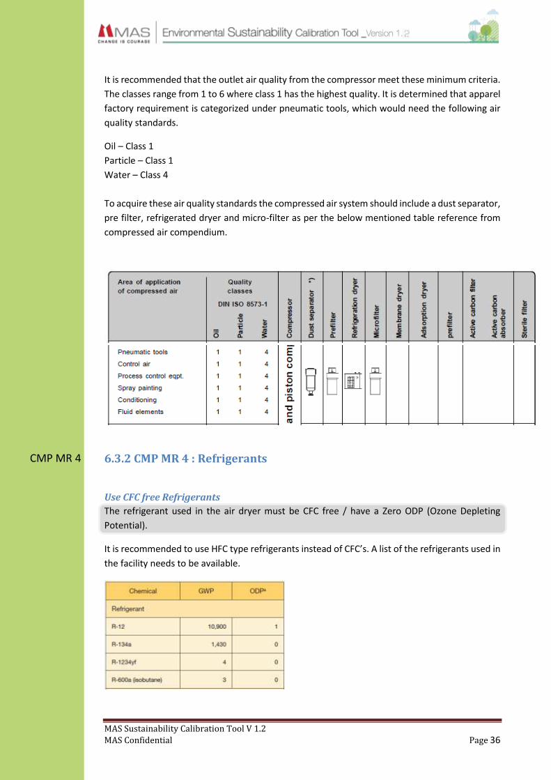
6.3.2 CMP MR 4 : Refrigerants
Use CFC free Refrigerants
The refrigerant used in the air dryer must be CFC free / have a Zero ODP (Ozone Depleting
Potential).
It is recommended to use HFC type refrigerants instead of CFC’s. A list of the refrigerants used in
the facility needs to be available.

MAS Sustainability Calibration Tool V 1.2
MAS Confidential Page 37
CMP RA 1
CMP RA 2
6.4.1 CMP RA 1 : Piping Material
Select the best type of pipe material based on pressure drop and internal smoothness.
Type Max Press
Max Press Advantages Disadvantages
Steel-Threaded 10-80 120 Inexpensive flow resistance
Quick installation high leakage Easy removal corrosion(un-galvanised)
Steel-Seamless 12-25 120 Inexpensive Skilled job
Wide selection corrosion(un-galvanised)
less Leakage
Stainless Steel 80 above 120 Corrosion proof Skilled job
low flow resistance Expensive
less Leakage Limited availability
Plastic 12.5 max N/A Corrosion proof Instability
Lightweight Skilled job
Smooth inside surface Cheap imitations
low flow resistance resistance to condensate
The material must meet the different criteria in protecting against corrosion and ensure
maximum operating temperature, maximum operating pressure, deliver low pressure loss and
low cost installation.
6.4.2 CMP RA 2 : Distribution System Pressure Management
Ensure that pipe sizing has been done so as to reduce losses due to pipe diameter changes. The
maximum pressure drop between the compressor and the end user should be no greater than 1
bar (including filter, dryer).
The pressure drop can be verified by connecting a pressure gauge to the furthest end user and
measuring the actual pressure drop.
∆𝑝 = 450 ×𝑞𝑐
1.85 × 𝑙
𝑑5 × 𝑝
Δp = Pressure Drop (bar)
qc = Air flow, FAD (l/s)
D = Internal pipe diameter (mm)
L = length of pipe (m)
P = Absolute initial pressure (a)

MAS Sustainability Calibration Tool V 1.2
MAS Confidential Page 38
A larger compressed air network can be divided into four main parts: risers, distribution pipes,
service pipes and compressed air fittings. The risers transport the compressed air from the
compressor plant to the consumption area. Distribution pipes split the air across the distribution
area. Service pipes route the air from the distribution pipes to the workplaces.
Table : Typical pressure drop in compressed air line for different pipe sizes considering 100cfm
Pipe nominal bore (mm) Pressure drop (bar) per 100 meters
Equivalent power loss (kW)
40 1.80 9.5
50 0.65 3.4
65 0.22 1.2
80 0.04 0.2
100 0.02 0.1
Reference : Sri Lanka Energy Audit Manual
Table: Pressure drop across other devices.
Description Pressure Drop(Bar)
Final Filter 0.1-0.5
Pipe System 0.2
Dust Filter 0.1-0.5
Dryer 0.1
Reference : Compressed Air Manual 2010 (Atlas Copco)
Table : Maximum Pressure drop across a distribution system
8 Bar and above 3 Bar and below
A Pipe System ΔP≤0.04 ΔP≤1.5% Pmax
1 Main Line ΔP≤0.04
2 Distribution Line ΔP≤0.04
3 Connection Line ΔP≤0.03
Reference : Compressed air compendium BOGE
The system must also have in place pressure regulating and pressure reducing valves where
appropriate. The pressure drop can be further reduced by using long curves and Y pieces instead
of knee joints and T pieces. Try to avoid abrupt changes in pipe diameter and consider isolating
some sections using non return valves for better access during a breakdown. Sufficient proof
must be shown that attempts have been made to optimize the compressed air network. This
network must be designed on a closed loop system to reduce losses. Separate sub-circuits to
facilitate emergency repair work.
All compressed air lines should be painted blue and marked showing the direction of flow (British
Standard 1710:1984).
Maximum air flow velocity of a compressed line should be less than 20 m/s to avoid excess noise
and turbulent flow. The distribution system can be designed with a 1.5-2% downward gradient
in the direction of the flow to capture condensate, though this is not very important for systems
that include refrigerated dryers.

MAS Sustainability Calibration Tool V 1.2
MAS Confidential Page 39
CMP MR 5
CMP RA 3
6.5.1 CMP MR 5 : Standard Operating Procedure (SOP)
The SOP for compressed air system must be displayed at the plant room. All operators must be
aware of the contents of the SOP.
The SOP for the compressed air system must follow the format shown below. Slight variations
are allowed depending on compressor model and manufacturer.
Standard Operating Procedure – Compressor
Prior To Starting
Make a visual inspection (secure guards, proper ventilation, free access to unit)
Check coolant level.
Make sure main discharge valve is open.
Turn the power on. (indicator will light)
Check direction of rotation at initial start or following power interruptions.
Starting Switch the ON/OFF switch to ON position. (Compressor will then start and load)
Normal / Emergency Stop
Switch the ON/OFF switch to OFF position. (compressor will unload and stop)
Press EMERGENCY STOP button. (compressor will stop immediately)
Turn off electrical isolator or disconnect.
Standard Operating Procedure – Dryer
1. Check the by-pass.
2. Activate current supply and switch the ON/OFF switch to ON.
3. Wait 5-10 minutes until machine has achieved its standard operating parameters.
4. Slowly open the air outlet valve and successively open the air inlet valve.
5. Close the by-pass (if available).
6. Check if the condensate drain is working properly.
7. Check if all connecting pipes are properly tightened and fixed.
8. Switch the ON/OFF switch to OFF position.
Caution : Dryer must be switched ON or OFF after first switching the compressor unit ON or OFF.
6.5.2 CMP RA 3 : Policies
A policy covering the compressed air system should be in place for the factory and should
cover the following topics.
New air line connections
Using compressed air for non-value addition processes.

MAS Sustainability Calibration Tool V 1.2
MAS Confidential Page 40
CMP MR 6 6.5.3 CMP MR 6 : Maintenance Schedule
The factory must have a maintenance schedule that covers all of the below mentioned topics.
The standard maintenance checklist can be found in the annexures section. Slight variations are
allowed depending on compressor model and manufacturer.
Table : Maintenance Schedule
Daily or before each operation Check for oil leaks.
Check lubricant level and fill as when necessary.
Drain receiver tank condensate.
Check for unusual noise and vibration.
Ensure belt guards and covers are in place.
Ensure area around unit is clean
Weekly Observe operation of safety valve.
Inspect air filter elements and clean as when necessary.
Monthly Inspect for air leaks (visually).
Check tightness of screws and bolts.
Inspect drive belts.
Clean exterior.
3Months/500Hours Change lubricant.
Drain compressor oil and clean oil sight glass.
Conduct comprehensive leak detection survey.
12Months/2000Hours Install maintenance pack/conduct service.
Change synthetic lubricant.
Replace filter element.
Reference: Ingersoll Rand O&M Manual
Table : Maintenance schedule for Dryer
Weekly Verify temperature on the control panel display.
Visually check if condensate is drained regularly.
Check the dew point temperature.
Monthly Clean the condenser. (with compressed air)
Ensure that unit is working properly after cleaning.
12Months/2000Hours Check if flexible tube used for condensate drainage is damaged.
Ensure connecting pipes are properly tightened & fixed.

MAS Sustainability Calibration Tool V 1.2
MAS Confidential Page 41
CMP MR 7
6.5.4 CMP MR 7 : leak detection and prevention program
Periodically check and rectify any compressed air leaks within the system in order to stop leakage
of air in the main network. The air leakage loss in the total system should be calculated before
searching for individual leaks in the network.
Studies show that 70% of leaks from an air main occur in the last few meters of the network
including T joints, switch couplings and air filter joints in sewing machines.
Simple Calculation
The simplest way of quantifying leakage (VL) is by using the following equation.
𝑉𝐿 =𝑉𝑇 × (𝑃𝑠 − 𝑃𝐹)
𝑡
VL = Volume of leakage (l/min)
VT = Volume of Receiver (l)
PS = Receiver pressure at start (bar)
PF = Receiver pressure at end (bar)
T = Time measured (min)
Firstly empty the compressed air receiver and plug in the supply line to the receiver after
making sure all consumer devices in the system are switched off. If there is a leak, the
receiver pressure will drop and the time taken for this could be measured.
Secondary Calculation
The consumer devices in the network should be switched off. The leaks in the system consume
compressed air and the network pressure will drop and the compressor must replace this
volume. The total running time of the compressor is measured over a period of time. Measuring
time should be for at-least 5 cycles for accurate readings.
Example:
A compressed air receiver with a pipe system has a volume of 1000L. Within 2 minutes
the pressure drops from 8 bar to 7 bar.
𝑉𝐿 =1000 × (8 − 7)
2= 500𝑙/𝑚𝑖𝑛

MAS Sustainability Calibration Tool V 1.2
MAS Confidential Page 42
𝑉𝐿 = 𝑉𝐶 × ∑𝑡𝑥
𝑇
VL = Leakage (m3/min)
VC = Free air delivery of the compressor (m3/min)
∑x = t1+t2+t3+t4+t5 (min)
T = Total time (min)
*∑t = average compressor loading (running) times.
Certain levels of leakage could be tolerated as per the below schedule.
Table : Accepted leakage percentage
5% Small networks (below 250 CFM)
7% Medium sized networks (250-300 CFM)
10% Large networks (300-500 CFM)
15% Very Large networks (above 500 CFM)
Reference : Compressed air compendium_BOGE
A leak detection survey should be carried out quarterly depending on the results of the past
surveys (persistent leaks should result in more frequent leak detection surveys). This survey
should be carried out preferably on a day the plant is shut down.
How to conduct a leakage test
Step 1: Close all the end user valves.
Step 2: Make note of the volume of the air receiver and piping. Start the compressor.
Step 3: Measure time taken to pressurize the system to the set pressure.
Step 4: Measure loading/unloading cycle time. Total volume of system divided by time
taken for unloading time will give you the leak rate.
Step 5: By conducting a walk-around audit make note of places where leaks are taking
place and mark accordingly (mark on separate drawing if action is planned for a later
date).
Step 6: Prioritize the leaks and attend to larger air flow leaks first.
MAS Sustainability Calibration Tool V 1.2
MAS Confidential Page 43
CMP MR 8
CMP RA 4
6.6 CMP MR 8 : Health and Safety
Comply with safety regulations mentioned in the factory ordinance and any other customer
requirements.
All pressure vessels should have safety valves and pressure gauges. Maximum pressure must be
displayed, along with Tested pressure and the next inspection date. Personal Protection
Equipment (PPE) must be available in the plant room and should be worn by the operator. The
following inspections should be carried out by a certified independent inspector.
Pressure vessel inspection – Every year
Internal Examination – Every 5 years
Pressure Test – Every 10 years
6.7 CMP RA 4 : Training
Systematic training programs must be conducted for maintenance team and compressed air end
users.
The factory must have at-least 2 qualified and sufficiently trained persons to operate the
compressed air system.
All designated compressor operators must take part in external training sessions conducted by
the supplier/manufacturer at least annually.
Training sessions should also be conducted for compressed air end users, such as sewing machine
operators and cleaning staff, on the correct uses and applications and creating awareness on the
ill effects of using compressed air incorrectly.
MAS Sustainability Calibration Tool V 1.2
MAS Confidential Page 44
AC MR 1
AC MR 2
7.0 Air Conditioning (AC)
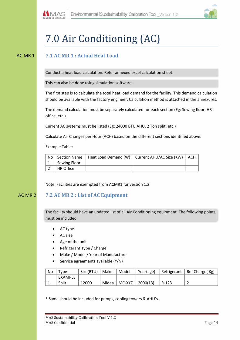
7.1 AC MR 1 : Actual Heat Load
Conduct a heat load calculation. Refer annexed excel calculation sheet.
This can also be done using simulation software.
The first step is to calculate the total heat load demand for the facility. This demand calculation
should be available with the factory engineer. Calculation method is attached in the annexures.
The demand calculation must be separately calculated for each section (Eg: Sewing floor, HR
office, etc.).
Current AC systems must be listed (Eg: 24000 BTU AHU, 2 Ton split, etc.)
Calculate Air Changes per Hour (ACH) based on the different sections identified above.
Example Table:
No Section Name Heat Load Demand (W) Current AHU/AC Size (KW) ACH
1 Sewing Floor
2 HR Office
Note: Facilities are exempted from ACMR1 for version 1.2
7.2 AC MR 2 : List of AC Equipment
The facility should have an updated list of all Air Conditioning equipment. The following points
must be included.
AC type
AC size
Age of the unit
Refrigerant Type / Charge
Make / Model / Year of Manufacture
Service agreements available (Y/N)
No Type Size(BTU) Make Model Year(age) Refrigerant Ref Charge( Kg)
EXAMPLE
1 Split 12000 Midea MC-XYZ 2000(13) R-123 2
* Same should be included for pumps, cooling towers & AHU’s.

MAS Sustainability Calibration Tool V 1.2
MAS Confidential Page 45
AC RA 1 7.3 AC RA 1 : Efficiency Calculation
Running efficiency for the existing air conditioning system should be calculated. This should be
conducted for chillers and package units larger than 10RT.
Performance of refrigeration equipment is indicated using different bases. The most commonly
used bases are Coefficient of Performance (COP), Energy Efficiency Ratio (EER) and Kilowatt per
Ton (kW/TR) rating.
𝐶𝑂𝑃 = 𝐶𝑜𝑜𝑙𝑖𝑛𝑔 𝑒𝑓𝑓𝑒𝑐𝑡 𝑔𝑒𝑛𝑒𝑟𝑎𝑡𝑒𝑑 (𝑘𝑊)
𝐸𝑛𝑒𝑟𝑔𝑦 𝐼𝑛𝑝𝑢𝑡 (𝑘𝑊)
𝐸𝐸𝑅 = 𝑂𝑢𝑡𝑝𝑢𝑡 𝐶𝑜𝑜𝑙𝑖𝑛𝑔 𝐶𝑎𝑝𝑎𝑐𝑖𝑡𝑦 (𝐵𝑡𝑢 𝑜𝑟 𝑘𝐶𝑎𝑙)
𝐸𝑙𝑒𝑐𝑡𝑟𝑖𝑐𝑎𝑙 𝐼𝑛𝑝𝑢𝑡 𝑃𝑜𝑤𝑒𝑟 (𝑘𝑊)
𝑆𝑝𝑒𝑐𝑖𝑓𝑖𝑐 𝐸𝑛𝑒𝑟𝑔𝑦 = 𝐼𝑛𝑝𝑢𝑡 𝑃𝑜𝑤𝑒𝑟 (𝑘𝑊)
𝑂𝑢𝑡𝑝𝑢𝑡 𝐶𝑜𝑜𝑙𝑖𝑛𝑔 (𝑇𝑅)
Energy Efficiency Ratio (EER) method is recommended for window, split and package type air
conditioning devices.
This kW/TR rating is widely used to express the performance of chillers. It denotes the power
input required to produce one tone of cooling input.
Typical COP and kW/RT of different Air Conditioner types are given below. Make sure the
system at each facility closely matches these values.
Type COP kW/RT @ full load
Window AC units 1.2 TO 1.3
Split AC units 1.25
Multi Split AC Units 1.2 TO 1.25
VRV AC Units 1.0
Package Units – Air Cooled 1.2-1.25
Package Units – Water Cooled 1.0-1.05
Chillers – Air Cooled 3.7-4.1 1.0-1.2
Chillers – Water Cooled 4.6-5.3 0.5-0.6
Pump Efficiency
𝑃𝑢𝑚𝑝 𝐸𝑓𝑓𝑖𝑐𝑖𝑒𝑛𝑐𝑦 =(𝑄 × 𝐻)
(𝑃𝑜𝑤𝑒𝑟 × 𝑀𝑒 × 𝐷𝑓)
Q = Flow rate (L/s) H = Pressure head + Suction lift (m) Me = Motor Efficiency Df = Transmission loss
Pump efficiency should be above 80% (rated), refer attached calculation excel sheet to
determine pump efficiency.

MAS Sustainability Calibration Tool V 1.2
MAS Confidential Page 46
AC MR 3 7.4 AC MR 3 : Standard Operating Procedures (SOP)
The SOP for cooling systems must be displayed at all times in plant room at all times. All
operators must be aware of the contents of the SOP.
The SOP must follow the below mentioned format. Slight variations are allowed depending on
compressor model and manufacturer.
7.4.1 SOP – Water Cooled Package Units
Prior to starting
1. Make a visual inspection (dampers, piping, fan belt)
2. Compressor oil should be visible through sight glass.
3. Check voltage.
4. Ensure sufficient load.
Starting
1. Turn on the power switch.
2. Turn on the condenser water supply.
3. Check the fan for rotation direction.
Normal/Emergency Stopping
1. To interrupt operation, press STOP button.
7.4.2 SOP – Water Cooled Chiller
Prior to starting / starting
1. Verify the chilled water pump and condenser water pump starter are ON.
2. Verify cooling tower is ON.
3. Check oil tank oil level.
4. Check the chilled water set-point.
5. Check the current limit set-point.
6. Press AUTO.
Normal/Emergency Stopping
1. Press STOP
2. After compressor and water pumps shutdowns turn pump contactors to OFF.

MAS Sustainability Calibration Tool V 1.2
MAS Confidential Page 47
7.4.3 SOP : Air cooled chiller
Prior to Starting
1. Visual Inspection (Oil level, Oil and chilled water leakage, Panel board and
cleanliness)
2. Check Voltage
Starting
1. Switch on all the AHUs
2. Turn on the chilled water pump (this will automatically start the chiller unit)
3. Check and make sure the working condition of the condenser fans.
Normal Stopping
1. Turn off the chilled water pump (automatically shut down the chiller)
2. Switch off the all AHUS
3. Clean the AHU filters
Emergency stopping
1. Turn off the chiller main switch
7.4.4 SOP : Air cooled package
Starting
1. Switch on the main panel
2. Switch on the blower fan from the compressor
3. Check the condenser fan
4. Check suction and discharge indicators, and make sure they are at the acceptable levels
stated by manufactures
5. Ensure there is no leakage of gas or oil of any kind
6. Check all unit’s ampere ratings and make sure they meet the requirements

MAS Sustainability Calibration Tool V 1.2
MAS Confidential Page 48
AC MR 4 7.5 AC MR 4 : Preventative Maintenance
A daily log sheet must be kept to monitor certain parameters
7.5.1 Water Cooled Package Unit (WCP)
Table : Maintenance Schedule – WCP
Weekly Check liquid line sight glass.
Check temperature drop across the filter driers.
(Replace if necessary)
Monthly Inspect unit air filter.
Clean/Replace if necessary
Inspect coils for excess moisture or icing.
Check condensate flow through drain pipe.
Check tension and condition of fan belts.
6 Months Inspect fan motor for proper lubrication.
Disconnect power & manually check fan rotation.
Check alignment of fan assembly sheaves.
Inspect, clean, tighten all electrical connections.
Inspect TXV sensing bulbs.
Drain & inspect the condenser water system.
Clean the condensers.
Reference: Trane water cooled package
7.5.2 Water Cooled Chiller (WCC)
Table : Maintenance Schedule – WCC
Daily Check chilled water entering & leaving temperatures.
Check condenser water entering & leaving temperatures.
Current drawn by compressor.
Oil level in oil sump.
Condenser pressure.
Evaporator pressure.
Check for unusual noise and vibration.
Annual Check setting and operation of control & safety devices.
Conduct refrigerant leak test.
Check starter contactors. Replace if required.
Check motor winding insulation.
Check motor amps draw.
Perform oil analysis.
Perform vibration analysis.
Check & adjust water flow.
Check & adjust interlocks.

MAS Sustainability Calibration Tool V 1.2
MAS Confidential Page 49
Clean condenser tubes.
Check evaporator insulation for condensate/leakage
Check refrigerant gas discharge pressure
Reference: Trane water cooled chiller
7.5.3 Air Cooled Package Unit (ACP)
Table : Maintenance Schedule – ACP
Daily Remove Filters & wash
Monthly Service Evaporator & condenser coils
Check blower motor belt tension
Check blower & fan motor bearings
Check suction & discharge pressure
Check compressor unit current
Check contactors, thermostat, sensors
Clean drain lines
Annual Carry out insulation test for compressor & fan motor
Service contactors
Reference: Trane water cooled package
7.5.4 Air Cooled Chiller (ACC)
Table : Maintenance Schedule – ACC
Weekly Clean filters
Monthly Check chiller operation
Check fan bearing
Clean cooling coils with high pressure water
Check pump gland
Check liquid & oil level in sight glass
3 Months Calibrate with computer program
6 Months Check all controls
Annual Sample compressor oil and replace if necessary
Leak check chiller
Check wiring connections
Reference: Trane water cooled package
7.5.5 Split Air Conditioner
Table : Maintenance Schedule – Split AC
3 Months Check Current
Check gas pressure
Check blower condition
Clean filters
Clean coil & drain pan
Clean/wash indoor/outdoor unit
Check & service compressor
Reference: Fujicool split AC

MAS Sustainability Calibration Tool V 1.2
MAS Confidential Page 50
7.5.6 Cooling Tower
Table : Maintenance Schedule – Cooling Tower
Daily Check for abnormal noise and vibration
Check for abnormal temperature differences
Monthly Check water distribution & sprinkler
Clean tower pan & drain
Apply protective coating if required
Quarterly Check belt tension & pulley alignment
Check fan guard, inlet louvers & fan blades
Check operational level of pan and adjust if required
Annual Clean the strainer of the tower
Reference: King Sun cooling tower
7.5.7 Air Handling Unit (AHU)
Table : Maintenance Schedule – Air Handling Unit (AHU)
Monthly Check belt tension, motor current, damper function
Check air filter & service
Quarterly Clean coil & drain pan
Check & adjust pulleys, V belts & motor base
Lubricate fan & motor bearings
Check and clean electrical components, panel service
Check exhaust fan
Wash filters
Annual Check and correct earth fault settings
Reference: York AHU
7.5.8 Fan coil Unit (FCU)
Table : Maintenance Schedule – Fan Coil Units (FCU)
Monthly Clean Filters
Quarterly Check electrical wiring & tighten
Clean drain pipes
6 Months Check condenser coil and clean if necessary
Reference: Uni-master FCU
7.5.9 Pumps
Table : Maintenance Schedule – Pumps
Daily Check abnormal noise and vibration
Check for cleanliness
Check contact points for wear & tear
Monthly Conduct visual inspection
Quarterly Apply grease to pump & motor bearings
Check loading amperage
Check electrical system

MAS Sustainability Calibration Tool V 1.2
MAS Confidential Page 51
AC MR 5
AC MR 5
7.6 AC MR 5 : Water Treatment
The following water purification steps are mandatory for an effective chilled water system.
Testing should be conducted monthly.
Table : Water quality at cooling tower basin
Parameter Recommended Levels
1 pH 7.20 – 8.50
2 Electrical Conductivity, µS/cm Below 2000
3 Total Dissolved Solids, mg/l Below 1000
4 Total Hardness, CaCO3 mg/l Below 500
5 Total Alkalinity, CaCO3 mg/l 150-750
6 Phosphate, PBTC mg/l 3-8
Reference : Willpower Analysis Report
Table : Water quality at chiller make-up water
Parameter Recommended Levels
1 pH 6.9-7.5
2 Electrical Conductivity, µS/cm Below 100
3 Total Dissolved Solids, mg/l Below 50
4 Total Hardness, CaCO3 mg/l Below 25
5 Total Alkalinity, CaCO3 mg/l 50-100
6 Chloride, Cl, mg/l Below 20
7 Silica Below 5
Reference : Willpower Analysis Report
To achieve these values it is recommended that the chilled water system has a softener plant &
sedimentation filter depending on the quality of raw water. In addition corrosion & scale
inhibitors, dispersants and algae (Biocide & micro-biocide) inhibitors should also be used to
control the water quality.
7.7 AC MR 6 : Training
All operators running AC systems must be sufficiently trained on AC operations. It is further
recommended that an annual refresher training course be conducted for the operators by a
verified 3rd party trainer.
Training should include at least one or more of the following;
- Energy efficiency
- Effective maintenance
- Best practices
- Safety / refrigerant handling
MAS Sustainability Calibration Tool V 1.2
MAS Confidential Page 52
AC RA 2 7.8 AC RA 2 : Best Practices
An AC evaluation for each facility should be carried out once in 2 years.
7.4.1 Best Practices – General Systems
Make sure the facility is running with the most suitable AC solution. Submit a shot write
up with relevant details.
Have in place efficient cooling systems in order to reduce the energy consumption after
first conducting a feasibility study.
A centralized Building Monitoring System (BMS) should be in place, which can remotely
monitor and control the AC system. It is recommended to control and display
temperature, humidity, CO2, AHU return air temperature, damper position & valve
position. It can also display chiller parameters such as load percentage, chilled water
temperature and loading amperes.
Conduct performance tests on equipment such as chillers, package units, AHU’s, pumps,
cooling towers and distribution systems every 2 years.
All heat generating equipment should be installed with heat extraction, isolation or
separation devices.
Heat recovery systems such as desiccant wheels should be installed.
For areas that produce high amounts of dust and fumes, it is recommended to carry out
a calculation to determine the optimum air exchange rate. This rate could typically be 8-
10 ACH.
Partitions must be in place to separate AC areas from non AC areas. These partitions can
be air curtains, plastic curtains or automatic speed (polythene) doors.
Make sure the building envelop is well insulated and has minimum air infiltration. 50mm
thick (density-32 kg/m3) glass-wool insulation along with double sided aluminium foil is
recommended for the roof.
7.4.2 Best Practices – Chiller System
Have in place VSD pumps for chilled water systems.
Ensure that the chiller is running at the highest corresponding efficiency loads based on
the recommended part load values. Conventional screw chillers are most efficient at 70-
80% of full load and VFD chillers are most efficient below 60% of full load, depending on
manufacturer specifications.
Optimum filters must be used to ensure good air quality. Flow velocity across the filters
should not be more than 2.5m/s. Filters should have a classification of MERV 9 or better.
Energy efficiency of the chiller could be improved by regulating the water temperature.
As the chilled water temperature in the chiller is usually between 7OC (leaving) and 12OC
(entering), it is recommended to increase the temperature of the water leaving the
system above 7OC. The incoming water to the condenser should be 3OC- 5OC lower than
the temperature of the outgoing water.

MAS Sustainability Calibration Tool V 1.2
MAS Confidential Page 53
Water cooled chillers should be installed with a by-pass system so that the cooling tower,
chiller & AHU has the option of being by-passed independently. This is useful during
chemical flushing of individual components of the system without impacting the other
components.
7.4.3 Best Practices – Water cooled condenser systems
It is recommended to install a VSD motor or twin speed fan for the cooling tower.
A chemical management plan that meets the water conservation objectives and controls
corrosion, scaling, sediment and biological growth should be implemented. Mineral content is
typically managed through a combination of bleed-off and chemical treatment that prevents
precipitation of dissolved solids. Water conservation can be optimised by ensuring that bleed-
off and chemical strategies are aligned.
Consider increasing the conductivity concentration ratio of the cooling tower from 4 cycles per
bleed-off to 12 cycles, thus reducing the amount of water that is bled out. Other water leaks
resulting from drift loss and leaks should be minimised.
2.4.4 Best Practices – AHU (air side)
Air Handling Units (AHU) above 15kW should be installed with temperature sensors and variable
speed drive motors. It is also recommended to use 2 way motorised valves for VSD AHUs and 3
way motorised valves for non VSD AHUs.
Condensate water from AHUs should be recovered thus enabling higher water savings & chiller
efficiency. Condensate water runoff should flow in to a single tank taking into consideration the
quality of the water collected. Collection in a single tank will make it easier for the water to be
pumped back into the cooling tower. It is recommended to use an insulated line to pump back
the water.
All chilled water ducting lines must be sufficiently insulated by using appropriate material,
correct thickness and suitable U values (Heat transfer coefficient). Piping material must be
chosen considering the temperature range of chilled water.
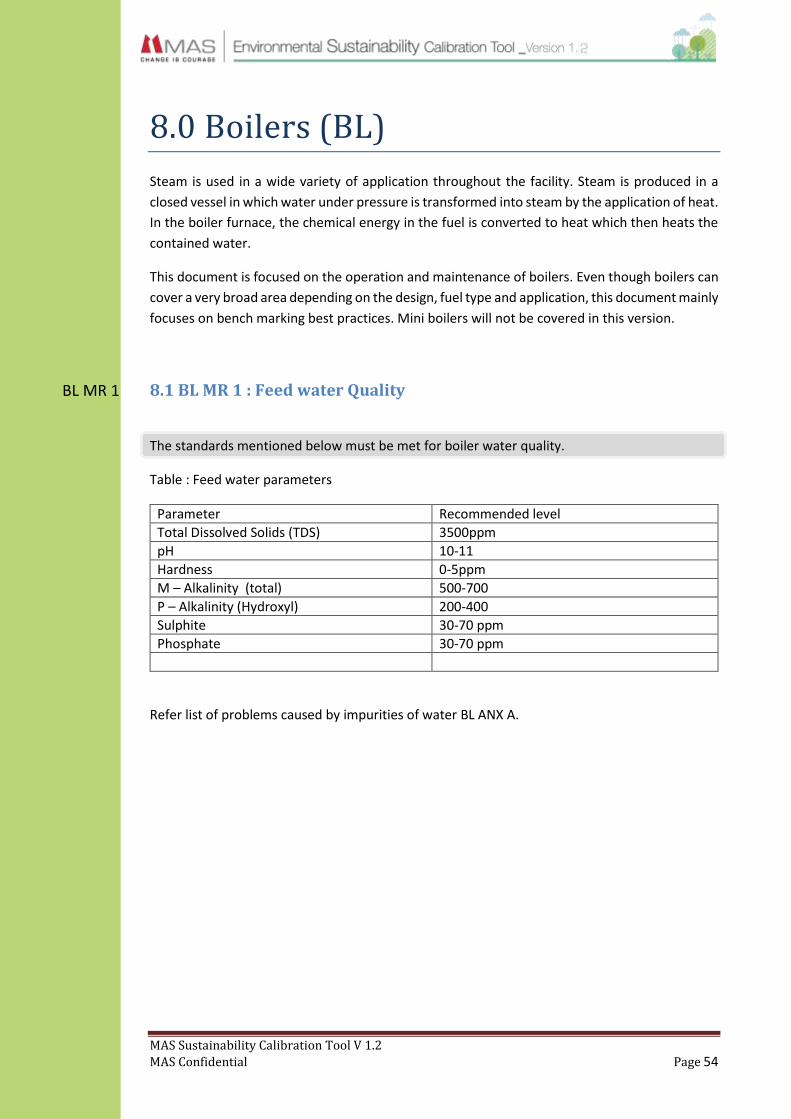
MAS Sustainability Calibration Tool V 1.2
MAS Confidential Page 54
BL MR 1
8.0 Boilers (BL)
Steam is used in a wide variety of application throughout the facility. Steam is produced in a
closed vessel in which water under pressure is transformed into steam by the application of heat.
In the boiler furnace, the chemical energy in the fuel is converted to heat which then heats the
contained water.
This document is focused on the operation and maintenance of boilers. Even though boilers can
cover a very broad area depending on the design, fuel type and application, this document mainly
focuses on bench marking best practices. Mini boilers will not be covered in this version.
8.1 BL MR 1 : Feed water Quality
The standards mentioned below must be met for boiler water quality.
Table : Feed water parameters
Parameter Recommended level
Total Dissolved Solids (TDS) 3500ppm
pH 10-11
Hardness 0-5ppm
M – Alkalinity (total) 500-700
P – Alkalinity (Hydroxyl) 200-400
Sulphite 30-70 ppm
Phosphate 30-70 ppm
Refer list of problems caused by impurities of water BL ANX A.
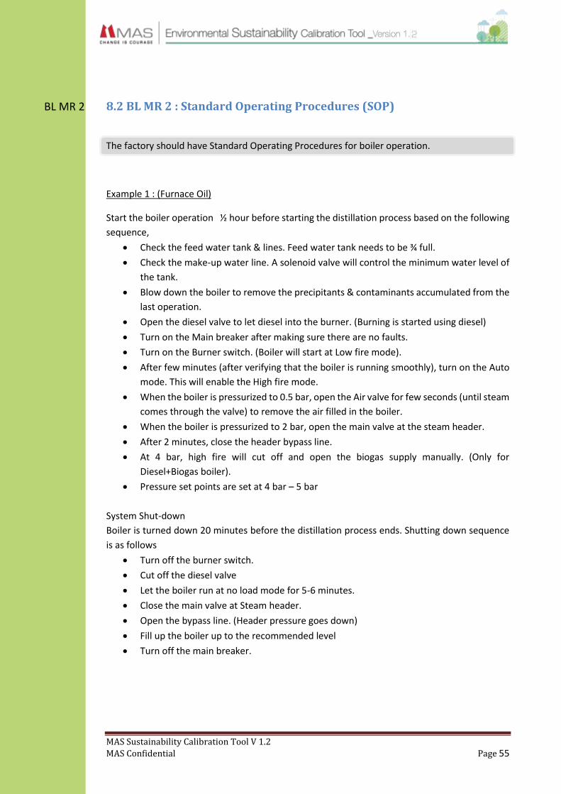
MAS Sustainability Calibration Tool V 1.2
MAS Confidential Page 55
BL MR 2
8.2 BL MR 2 : Standard Operating Procedures (SOP)
The factory should have Standard Operating Procedures for boiler operation.
Example 1 : (Furnace Oil)
Start the boiler operation ½ hour before starting the distillation process based on the following
sequence,
Check the feed water tank & lines. Feed water tank needs to be ¾ full.
Check the make-up water line. A solenoid valve will control the minimum water level of
the tank.
Blow down the boiler to remove the precipitants & contaminants accumulated from the
last operation.
Open the diesel valve to let diesel into the burner. (Burning is started using diesel)
Turn on the Main breaker after making sure there are no faults.
Turn on the Burner switch. (Boiler will start at Low fire mode).
After few minutes (after verifying that the boiler is running smoothly), turn on the Auto
mode. This will enable the High fire mode.
When the boiler is pressurized to 0.5 bar, open the Air valve for few seconds (until steam
comes through the valve) to remove the air filled in the boiler.
When the boiler is pressurized to 2 bar, open the main valve at the steam header.
After 2 minutes, close the header bypass line.
At 4 bar, high fire will cut off and open the biogas supply manually. (Only for
Diesel+Biogas boiler).
Pressure set points are set at 4 bar – 5 bar
System Shut-down
Boiler is turned down 20 minutes before the distillation process ends. Shutting down sequence
is as follows
Turn off the burner switch.
Cut off the diesel valve
Let the boiler run at no load mode for 5-6 minutes.
Close the main valve at Steam header.
Open the bypass line. (Header pressure goes down)
Fill up the boiler up to the recommended level
Turn off the main breaker.

MAS Sustainability Calibration Tool V 1.2
MAS Confidential Page 56
Example 2 : (Bio mass)
Verify that the main steam valve is closed.
Ensure that the feed water level is at the correct level.
Make sure that the valves in the feed water line are opened.
Test for right functionality of both the feed water pumps.
Make sure that all blow-down valves are closed properly.
Air venting valves of the boiler need to be kept opened during initial firing for some time
and then should be closed.
Fill softener water through feed water pump into boiler until it reaches the correct level.
During this operation, make sure switches of both feed water pumps are in the AUTO
position. Also verify that the feed water pump stops automatically when the water level
reaches the set level.
During the initial feeding of fire wood logs to fire chamber, make sure the fire wood is
dry and the size is of the fire wood is less than 5inch diameter.
Make sure fire wood is weighed and that the quantity does not exceed the quantity
recommended by the manufacturer.
Small pieces of dry firewood should be stacked close to the doors of the fire wood
chamber and pour kerosene oil (half a litre) before firing.
After small fire wood pieces are burned over switch on IDF fan and maintain speed at
300rpm.
Make sure scrubber is working together with the IDF fan.
Switch on the FD fan as other fire wood is started to be burnt
Switch on the saw dust feeding system after whole firewood bed catches fire.
Open blow down valve for 90 seconds, when the steam pressure crosses 5bar
Verify that the firing stops when steam reaches 9 bar.
Communicate with steam consumers and open valve as and when they require steam.
Ensure that the main safety valve of the boiler is functioning at set pressure.
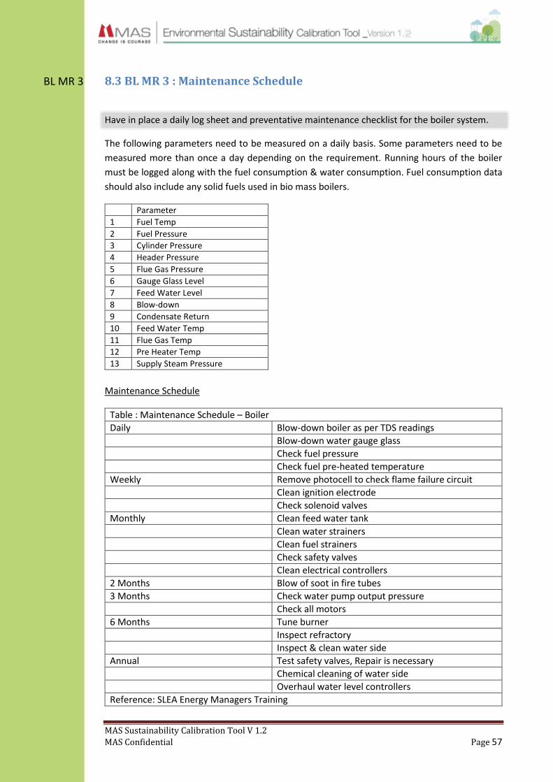
MAS Sustainability Calibration Tool V 1.2
MAS Confidential Page 57
BL MR 3 8.3 BL MR 3 : Maintenance Schedule
Have in place a daily log sheet and preventative maintenance checklist for the boiler system.
The following parameters need to be measured on a daily basis. Some parameters need to be
measured more than once a day depending on the requirement. Running hours of the boiler
must be logged along with the fuel consumption & water consumption. Fuel consumption data
should also include any solid fuels used in bio mass boilers.
Parameter
1 Fuel Temp
2 Fuel Pressure
3 Cylinder Pressure
4 Header Pressure
5 Flue Gas Pressure
6 Gauge Glass Level
7 Feed Water Level
8 Blow-down
9 Condensate Return
10 Feed Water Temp
11 Flue Gas Temp
12 Pre Heater Temp
13 Supply Steam Pressure
Maintenance Schedule
Table : Maintenance Schedule – Boiler
Daily Blow-down boiler as per TDS readings
Blow-down water gauge glass
Check fuel pressure
Check fuel pre-heated temperature
Weekly Remove photocell to check flame failure circuit
Clean ignition electrode
Check solenoid valves
Monthly Clean feed water tank
Clean water strainers
Clean fuel strainers
Check safety valves
Clean electrical controllers
2 Months Blow of soot in fire tubes
3 Months Check water pump output pressure
Check all motors
6 Months Tune burner
Inspect refractory
Inspect & clean water side
Annual Test safety valves, Repair is necessary
Chemical cleaning of water side
Overhaul water level controllers
Reference: SLEA Energy Managers Training
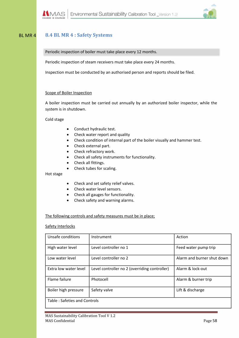
MAS Sustainability Calibration Tool V 1.2
MAS Confidential Page 58
BL MR 4 8.4 BL MR 4 : Safety Systems
Periodic inspection of boiler must take place every 12 months.
Periodic inspection of steam receivers must take place every 24 months.
Inspection must be conducted by an authorised person and reports should be filed.
Scope of Boiler Inspection
A boiler inspection must be carried out annually by an authorized boiler inspector, while the
system is in shutdown.
Cold stage
Conduct hydraulic test.
Check water report and quality
Check condition of internal part of the boiler visually and hammer test.
Check external part.
Check refractory work.
Check all safety instruments for functionality.
Check all fittings.
Check tubes for scaling. Hot stage
Check and set safety relief valves.
Check water level sensors.
Check all gauges for functionality.
Check safety and warning alarms.
The following controls and safety measures must be in place;
Safety Interlocks
Unsafe conditions Instrument Action
High water level Level controller no 1 Feed water pump trip
Low water level Level controller no 2 Alarm and burner shut down
Extra low water level Level controller no 2 (overriding controller) Alarm & lock-out
Flame failure Photocell Alarm & burner trip
Boiler high pressure Safety valve Lift & discharge
Table : Safeties and Controls

MAS Sustainability Calibration Tool V 1.2
MAS Confidential Page 59
BL MR 4
.
Oil temperature indictor 1 no Local cum panel mounted to indicate oil temperature
Pressure switch 2/3 nos For firing positions of burner
Photo resistant cell 1 no Flame failure and audio visual alarm
Temperature controller 1 no To control oil temperature in burner heater before nozzle
with audio visual alarm and burner trip
Sequence controller 1 no To control sequence of firing, pre-purging etc.
Modulating mechanism 1 no Stepped/three stage modulating
Low oil pressure switch 1 no To trip burner with audio visual alarm
Level controller 2 nos To regulate feed water pump operation and trip burner in
case of very low level with audio visual alarm
8.5 BL MR 5 : Operator Training
Boiler should be operated by an authorised person who holds a boiler attendant’s certificate.
Class III– up to 2000lb/hr
Class II – up to 6000lb/hr
Class I – Any capacity.
Annual refresher training programs should be conducted for the boiler operator focusing on
energy saving and systems optimisation. The factory must have at-least 2 qualified and
sufficiently trained persons to operate the boiler.

MAS Sustainability Calibration Tool V 1.2
MAS Confidential Page 60
BL RA 1 8.6 BL RA 1 : Heat recovery & Energy optimising
8.6.1 Boiler Blow-down
Blow-down is a necessary task in boiler operation intermittently reducing the concentration of
solids in the boiler. The frequency of blow-down depends on the quality of the feed water, the
use of the live steam and the quality of the make-up water.
In practice we see a blow-down of 0 % to 15 % of feed water. The consequence of too much
blow-down is an increase in fuel consumption. Too little blow-down also increases fuel
consumption, because it may lead to scale formation at the water-side of the boiler.
8.6.2 Reducing surface losses
It is important to sufficiently insulate the boiler to avoid heat losses. Regular maintenance must
also be conducted to reduce soot deposit on heat transfer surfaces and scale deposit on the
water-side. Both these could reduce the boiler efficiency by 5 to 10.5%. An additional 70% of
heat losses can be avoided by floating a layer of 45mm poly-propelyn balls on the surface of the
condensate.
8.6.3 Air pre-heating
A 1% fuel saving could be obtained by pre-heating the incoming air by 20OC more than the
ambient temperature, using the waste heat recovery unit. This can be done by forcing the
incoming air through a heat exchanger that passes through the heated flue gas. This saving is
achieved by fuel which would otherwise have had to be burned to raise the air temperature.
Air-fuel ratio
The objective of good combustion is to release the total energy in the fuel. Complete combustion
is only possible in the presence of an adequate supply of oxygen. If the supply of oxygen is lower,
incomplete combustion takes place. On the other hand if the supply of oxygen is more,
combustion efficiency is reduced as heat is absorbed from the combustion.
Table : Recommended excess air levels for various fuels
Fuel Excess air (% by wt) Efficiency (%)
1 Furnace oil, Diesel 17-22 85
2 Fire wood 25-40 70
3 Baggases 25-35 70
4 Gas 5-7 88
5 Paddy Husk 25-35 70
Reference : SEA Energy Auditor Program

MAS Sustainability Calibration Tool V 1.2
MAS Confidential Page 61
BL RA 1
Maintaining the correct air fuel ratio at the combustion stage is very important; a 5% reduction
in excess air increases the boiler efficiency by 1%. This ratio can be kept at the optimum level
using a flue gas analyser, oxygen analyser or through effective maintenance.
8.6.4 Economiser & condensate recovery
It is recommended to recover condensate and to insulate the recovery lines to ensure minimum
heat loss. When feed water is kept above 80OC, the dissolved oxygen escapes from the water,
resulting in a corrosion free environment inside the boiler. Flash steam can be recovered from
blow-down water and used to pre heat boiler feed water.
The function of the economiser is to increase the temperature of the feed water before it enters
the boiler by passing it indirectly through the flue gas. This would save on fuel energy that would
be required to heat this water. A 6OC rise in feed water temperature corresponds to a 1% saving
in boiler fuel consumption.
8.7 BL RA 2 : Operational Improvements
8.7.1 Monitor operational performance
It is recommended to analyse the performance of boiler operations on a daily basis.
1. Boiler fuel yield. (Steam tons/fuel ton/Wood).
2. Makeup water (water cubic meters / Steam ton)
3. Electricity (Kwh/Steam tone)
For calculating above performance indicators, it is necessary to measure fuel consumption, water
consumption, steam generation and electricity consumption daily.
Automatic combustion air controlling system with flue gas oxygen analyser.
It is recommended to install a flue gas oxygen analyser to control combustion air motor speed at
set oxygen levels; 11-12% for biomass boilers and below 5% for HFO boilers. This ensures
efficient combustion and reduces electricity consumption.

MAS Sustainability Calibration Tool V 1.2
MAS Confidential Page 62
8.7.2 Instrumentation
It is recommended to have the following instrumentation in place.
No. Item Qty Description
1 Water level controllers 2nos For feed pump operation and low water level alarm
2 Over-ride controller 1nos For lockout under extra low water level alarm
3 Steam pressure gauge with cock 1nos For display of boiler steam pressure
4 Water level gauge assembly 2nos For display of water level in the boiler
5 Switch gears, relays connectors 1set For individual controls of equipment through control panel (for lockout)
6 Audio visual alarm 1set In case of unsafe operation for lockout under extreme conditions
7 Pressure and temperature gauge with thermostat
1set For burner operation
8 Control panel 1set For housing above instruments and switch gears
9 Steam to fuel ratio monitoring system
1set To monitor and display the boiler efficiency on-line, using necessary meters, instrumentation and hardware
10 Main valves for boiler 2nos For safety (isolation valve)
11 Automatic blow-down control 1set
12 Water flow meters 1set
13 Steam flow meters 1set
14 Biomass weighing system 1set
15 Blow-down heat recovery 1set
Flow meters are necessary to measure water, fuel and steam generation. These three
measurements are needed in calculating boiler efficiency.
Temperature monitoring at stack is a mandatory requirement for boilers that run on
fossil fuel.
Temperature at the following locations has to be measured as they are critical for
calculating boiler efficiency.
o Temperature of combustion air.
o Temperature of makeup water.
o Temperature of exhaust air at inlet and outlet of APH. (Air Pre Heater)
o Temperature of exhaust air at inlet and outlet of WPH. (Water Pre Heater)
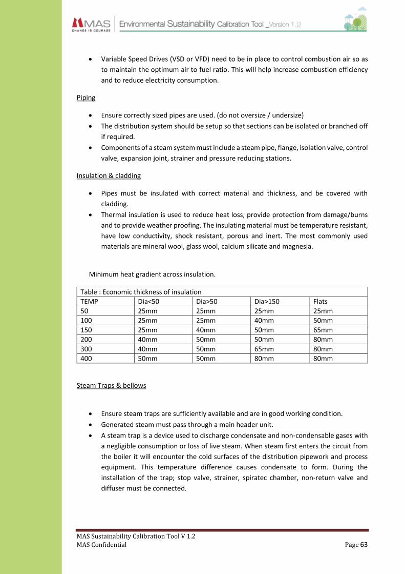
MAS Sustainability Calibration Tool V 1.2
MAS Confidential Page 63
Variable Speed Drives (VSD or VFD) need to be in place to control combustion air so as
to maintain the optimum air to fuel ratio. This will help increase combustion efficiency
and to reduce electricity consumption.
Piping
Ensure correctly sized pipes are used. (do not oversize / undersize)
The distribution system should be setup so that sections can be isolated or branched off
if required.
Components of a steam system must include a steam pipe, flange, isolation valve, control
valve, expansion joint, strainer and pressure reducing stations.
Insulation & cladding
Pipes must be insulated with correct material and thickness, and be covered with
cladding.
Thermal insulation is used to reduce heat loss, provide protection from damage/burns
and to provide weather proofing. The insulating material must be temperature resistant,
have low conductivity, shock resistant, porous and inert. The most commonly used
materials are mineral wool, glass wool, calcium silicate and magnesia.
Minimum heat gradient across insulation.
Table : Economic thickness of insulation
TEMP Dia<50 Dia>50 Dia>150 Flats
50 25mm 25mm 25mm 25mm
100 25mm 25mm 40mm 50mm
150 25mm 40mm 50mm 65mm
200 40mm 50mm 50mm 80mm
300 40mm 50mm 65mm 80mm
400 50mm 50mm 80mm 80mm
Steam Traps & bellows
Ensure steam traps are sufficiently available and are in good working condition.
Generated steam must pass through a main header unit.
A steam trap is a device used to discharge condensate and non-condensable gases with
a negligible consumption or loss of live steam. When steam first enters the circuit from
the boiler it will encounter the cold surfaces of the distribution pipework and process
equipment. This temperature difference causes condensate to form. During the
installation of the trap; stop valve, strainer, spiratec chamber, non-return valve and
diffuser must be connected.

MAS Sustainability Calibration Tool V 1.2
MAS Confidential Page 64
8.7.3 Reducing emission
The facility is recommended to install a dust collector and wet scrubber for biomass boilers.
In a wet scrubber, the polluted gas stream is brought into contact with the scrubbing liquid; by
spraying it with the liquid, by forcing it through a pool of liquid, or by some other contact method.
A wet scrubber removes pollutants from the flue gas generated by a furnace.
A dust collector is used to enhance the quality of air released from industrial and commercial
processes by collecting dust and other impurities from air or gas. Designed to handle high-
volume dust loads, a dust collector system consists of a blower, dust filter, a filter-cleaning
system and a dust receptacle or dust removal system.
Necessary steps must be taken to ensure that the flue gases meet the best practice parameters.
These regulations are covered in the Emissions Calibration Tool.
8.7.4 Calculate efficiency
Direct Method Calculation
Boiler Efficiency η =𝐻𝑒𝑎𝑡 𝑂𝑢𝑡𝑝𝑢𝑡
𝐻𝑒𝑎𝑡 𝐼𝑛𝑝𝑢𝑡× 100 =
𝑄×(ℎ𝑔−ℎ𝑓)
𝑞 ×𝐺𝐶𝑉
Q: Quantity of steam generated per hour (kg/hr)
Q: Quantity of fuel used per hour (kg/hr)
hg: Enthalpy of saturated steam (kcal/kg of steam)
hf : Enthalpy of feed water (kcal/kg of water)
GCV : Gross calorific value of fuel (kcal/kg of fuel

MAS Sustainability Calibration Tool V 1.2
MAS Confidential Page 65
IEQ MR 1
IEQ RA 1
9.0 Indoor Environment Quality (IEQ)
9. 1 CO2 / Fresh Air Management
9.1.1 IEQ MR 1 : Indoor CO2 Management
The Carbon dioxide concentration inside the factory should not exceed 1500ppm. An annual CO2
audit may be carried out to monitor these values.
The normal concentration of CO2 in outdoor air is between 300-400 ppm. CO2 level in office
buildings typically range between 350 – 2500 ppm. It has been demonstrated that levels above
1000 ppm tend to result in health complains and above 5000 ppm is considered a health hazard.
LEED EBOM V3 stated that the maximum allowable indoor CO2 concentration cannot be greater
than 530 ppm above corresponding outdoor levels or 1000 ppm absolute.
Carbon dioxide test must be conducted on an annual basis to ensure building continues to adhere
to the indoor air quality standards. These levels must be checked in all occupied areas. This can
be carried out as an in-house audit. A portable Non-Dispersive Infrared (NDIR) CO2 sensor is
recommended for this (A NDIR sensor is a simple spectroscopic device often used as gas
detector).
Control methods for CO2 concentration through fresh air are given in the annexures.
Note 1: The maximum tolerance level for V1.2 will be 1500 ppm
Note 2: All new / upgrade AC projects must include a design criteria for CO2 to be below
1000ppm or follow ASHRAE 62.1 (Given in Version 2.0)
9.1.2 IEQ RA 1 : Permanently Installed CO2 Sensors
Install permanent C02 sensors to measure CO2 concentrations in order to maintain adequate
outdoor air ventilation rates inside the building.
CO2 concentrations are an indicator of air-change effectiveness where increased levels suggest
inadequate ventilation. With this information ventilation systems can be designed for actual
conditions thus saving on energy usage.
The building should have CO2 sensors in densely occupied spaces.
The sampling location must be between 3 and 6 feet above floor level, which known as the
breathing zone. Test and calibrate the sensors to have an accuracy of 75ppm or 5% of the
reading, whichever is greater.
MAS Sustainability Calibration Tool V 1.2
MAS Confidential Page 66
IEQ RA 2
The calibration of the sensors must be carried out once every 5 years or as per the
manufacturer’s recommendation. Monitor and trend the CO2 concentration in intervals of 30
minutes and calibrate the system to generate an alarm visible to the systems operator if the CO2
concentration rises more than 15% above the corresponding minimum outdoor rate specified in
ASHRAE standard 62.1-2007.
Sensors connected to the BMS system are recommended to have audio visual alarms for high
CO2 concentrations.
9.1.3 IEQ RA 2 : Automated System For Fresh Air Management
Have in place a Building Management System (BMS) which is connected to at-least the AC
system. Connecting machinery, lighting and heat generation is recommended based on
feasibility.
OR
Availability of demand controlled dampers that can control the fresh air flow in to the building.
The purpose of this is to provide the capability for monitoring the ventilation system in order to
sustain occupant comfort and well-being. It is recommended to install a continuous monitoring
system that provides feedback on the performance of the ventilation system to ensure that it
maintains the minimum outdoor airflow rates and be capable of measuring and controlling the
conditions within 15% of the design rates. Monitoring should also be performed for at least 80%
of the buildings total outdoor air intake (LEED EBOM V3).

MAS Sustainability Calibration Tool V 1.2
MAS Confidential Page 67
IEQ RA 3
9.2 Particle Management / Volatile Organic Compounds
9.2.1 IEQ RA 3 : Environment Monitoring Test
Facility is required to conduct an Indoor Environment Monitoring Test annually. This will cover
Dust, Noise, Light and Heat levels within the facility. Ensure the readings are below
recommended values.
Use MERV 09 (Bag filter 70-90%) or better filters in Air Handling Units (AHU’s).
It is necessary to have in place filtration media for all the outdoor air intakes. The strength of the
filtration, known as the Minimum Efficiency Reporting Value (MERV) shall depend on the
national guidelines and building best practice schemes. Pre-filters can also be used where
necessary. As per LEED-EB guidelines the filtration should have MERV 09. This translates to a
normal (bag) filter with an efficiency of 70-90%.
Establish and follow a regular schedule for maintenance and replacement of these filtration
media according to the manufacturer’s recommended intervals.
It is also recommended to have in place a permanent entryway system at least 10 feet long in
the primary direction of travel to capture dirt and particles entering the building (LEED NC V3).
Adhere to the maximum permissible levels stated in the National Environmental (Ambient Air
Quality) Regulations, 1994, published in Gazette Extraordinary, for particulate matter. (This is
covered in the environment monitoring test.)
The indoor noise level should not exceed the permitted levels mentioned in the National
Environmental (noise control) Regulations, 1996. (This is covered in the environment monitoring
test.)
Required parameters are listed in annexures. These requirements will be mandated in
Calibration Tool Version 2.
MAS Sustainability Calibration Tool V 1.2
MAS Confidential Page 68
IEQ RA 4
IEQ MR 2
9.2.2 IEQ RA 4 : VOC Emissions Test
It is recommended that the facility conduct a Volatile Organic Compound (VOC) test.
The VOC test may be carried out in the bonding, moulding & printing sections. The purpose of
this is to make sure no VOC’s are present in the indoor atmosphere. If VOC’s are found then it is
recommended to conduct this VOC test annually. It is also recommended to conduct a VOC test
at the introduction of new product or process that may contain VOC’s.
It is also recommended to use low VOC products for applicable operations such as cleaning
chemicals and painting. Use green seal certified products where applicable. Avoid products
containing formaldehyde, for example in carpets, wall panels and cabinetry. Measures need to
be taken to control and mitigate random build-up of VOCs.
9.3 Fume Extraction / Contaminant Management
9.3.1 IEQ MR 2 : Indoor smoking
Smoking indoors is banned in all facilities.
Environmental tobacco smoke is both the smoke given off directly from ignited tobacco products
and smoke inhaled by smokers. This smoke contains a wide amount of carcinogenic chemicals
which can lead to asthma, bronchitis, pneumonia, lung cancer and heart disease. To minimize
exposure to building occupants, smoking is strictly prohibited in all indoor areas. Due to these
negative health effects indoor smoking is strictly prohibited in the buildings.
Plan for outdoor Smoking
If there is a designated smoking area, proper signage should be displayed and the area should be
located at least 25 feet away from building entrances, windows and air intakes. The purpose of
this is to reduce the exposure of building occupants to the harmful effects of environmental
tobacco smoke.

MAS Sustainability Calibration Tool V 1.2
MAS Confidential Page 69
IEQ RA 5 9.3.2 IEQ RA 5 : Fume Extraction for specialized functions
Specialized machines emitting known toxins such as VOC’s and carcinogens must be extracted
from source. No recirculation of this air should be allowed.
Equipment such as photo process machines, clothes driers, and grinding machinery may have
exhaust duct collars for connecting ductwork that collect and remove contaminants. The
Standard requires that the discharge from such equipment be ducted directly to the outdoors.
This is also applicable for bonding & molding machines, soldering & stain removing operations
and other specialized operations within the facility.
In addition a total VOC audit should be conducted in the identified area and total VOC limit
should not exceed 500 µg/m3. This audit should be carried out annually and is conducted in Sri
Lanka by ITI and SGS.
MAS Sustainability Calibration Tool V 1.2
MAS Confidential Page 70
WE MR 1
10.0 Water Efficiency (WE)
10.1 Water Sources
All water entering the site must be metered, monitored and sufficiently treated to meet the end use criteria. In addition, drinking water must also be tested.
The main consumption of water at each location comprises of process water directly linked to the production and non-process water which used for all other requirements. Raw water may enter the facility premises in one or more of the following methods
- City water(Pipe Bourne) - Surface water - Ground water - Rainwater - Other (water bowsers, external tankers, water dispensers)
This water is used for Process Consumption, Human Consumption, Utilities and Gardening.
The quality of waste water discharge must be analysed on a quarterly basis and should be within the limits stipulated by the National Environmental Act and BOI environmental guidelines.
Quality measurements must be carried out for Potable Water at all facilities on a Quarterly basis.
These measurements must be carried out by an accredited third party laboratory. For example: University of Moratuwa, Industrial Technology Institute (ITI), National Water Supply and Drainage Board (NWSDB) etc.
Any deviation from the respective standards should be addressed immediately and adequate corrective and preventive action should be taken.
10.1.1 WE MR 1 : Source Metering
Each plant must have Main Flow Meters for all incoming sources to measure the total water
input to the facility.
This would enable each facility to keep track of their water usage patterns and easily identify if
any discrepancies take place. The recording of these meters must take place on a daily basis.
Accurate, timely and complete reporting to Eco Tracker on a monthly basis must be executed
by facility representatives.

MAS Sustainability Calibration Tool V 1.2
MAS Confidential Page 71
WE MR 2
WE RA 1
10.1.2 WE MR 2 : Sub Metering
Water used for Process and Non-process must be able to be identified separately.
The main measurement of water is based on Process Water and Non-Process Water (Human
Consumption, Utilities and Gardening). Therefore, it is required to measure these separately to
facilitate the analysis of water usage.
Water consumption should be measured and reported on the following bases:
Process water – Litres per kg of production. (Process water is relevant to Fabric and Apparel other facilities: Silueta, Linea Intimo & Prym)
Non Process water – litres per Full time equivalent.
It is recommended that facilities implement a sub-metering system most meaningful to its consumption structure.
Accurate, timely and complete reporting to Eco Tracker on a monthly basis must be executed by facility representatives by the 20th of every month.
10.1.3 WE RA 1 : Additional Sub metering
It is recommended that the following sections are also Sub-metered to ensure effective management of resources and reduction of wastage.
Apparel Plants Fabric Plants / Apparel Other Plants
Cooling tower Process users (Dyeing , Washing and Finishing)
Toilets Utilities (Boilers, AC)
Canteen & Kitchen Toilets
Irrigation & outdoor usage Canteen & Kitchen
Treated Waste Water discharge Irrigation & outdoor usage
Recycled Waste Water for Reuse Treated Waste Water Discharge
Accurate, timely and complete reporting to Eco Tracker on a monthly basis must be executed by facility representatives by the 20th of every month.
MAS Sustainability Calibration Tool V 1.2
MAS Confidential Page 72
WE MR 3
10.1.4 WE MR 3 : Treatment of raw water
The raw water used at the facility must be treated appropriately and adequately as per the Water Source to ensure it meets the quality parameters for its designated usage. Drinking water quality must meet the parameters set in Drinking Water Standards of Sri Lanka (SLS 614:1983):WE ANX A
10.1.4.1 Treatment for Process Water
Treatment will occur as per the requirement of the Process , Machinery and other equipment used. However a Softener plant is recommended to keep the Total Hardness below 5 PPM. pH of the treated water must be 7 +/- 0.5.
10.1.4.2 Treatment for Non Process Water
Non-process water used for drinking, cooking and in washrooms may be treated in order to achieve the required quality. The treatment schemes for non-process water may include the following steps depending on the quality of the raw water.
Step 1 Multimedia filter / Rapid sand filter
Step 2 Activated carbon adsorption
Step 3 Softener plant (depends on raw water hardness)
Step 4 Advanced membrane filter (depends on raw water quality)
Step 5 PH correction
Step 6 Disinfection (Ultra violet, Chlorination, Ozonation)
In the case of multimedia & UV filters, it is mandated to have a standby unit. Pipe borne Drinking Water parameters must meet SLS 614:1983 standard and Bottled Drinking Water Shall meet the SLS 894 Standard.
Sample Table: Different Water Sources and their recommended treatment schemes. (Based on Raw Water Quality)
No. Water Source Final Use Treatment Steps
1 Well water Drinking Depending on the water quality, all the above steps may stay the same or reduced. (Ex: Avissawella Vs. Kilinochchi)
Gardening None (as it is).
2 City water Drinking None for online. But if an in-house sump is used, Step 6 should be incorporated.
Gardening None

MAS Sustainability Calibration Tool V 1.2
MAS Confidential Page 73
WE RA 2
WE MR 4
Drinking water quality parameters must be monitored monthly.
10.1.5 WE RA 2 : Sustainable Sourcing
Existing Wells
If the facility receives its water from a tube well, the ground water availability of the respective
well must be monitored (depth & yield) in order to ensure the water yield and water tables are
not depleted. For this, a pumping test can be carried out by the National Water Supply &
Drainage Board (NWSDB) annually and a nearby open well can be used as the year-on-year
reference for the water level.
New Wells
In the case of constructing a new tube well, a hydro-geological survey and a pumping test (24
hours test) must be carried out by consulting the hydro-geological division of the National
Water Supply and Drainage Board (NWSDB).
10.2 Waste Water
There are two broad categories of waste water discharged from MAS facilities :
Industrial Waste Water (Effluent) – Liquid discharge from all processes and utilities (Dye house ,
Utility drains , Labs etc.)
Non-Industrial Waste Water (Sewage) – Liquid discharge due to human consumption (Canteen,
Kitchen, Toilets , Washrooms etc.)
10.2.1 WE MR 4 : Treating and Testing of Waste Water
All waste water must be treated within the factory premises before being discharged.
In the case that the facility is situated in a BOI zone that has a central waste water treatment plant the discharge must meet the BOI influent requirements. (WE ANX D). The discharge water must meet the tolerance limits stated in the National Environmental Act (NEA) No.47 of 1980. (WE ANX B,C,D)
The treated discharge water must be tested once in every 3 months for pH, BOD, COD, TSS, Oil & Grease, Amonical Nitrogen and once a year for all the parameters specified in the NEA. Test reports should be filed for future reference. (WE ANX B,C,D)
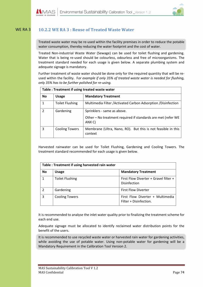
MAS Sustainability Calibration Tool V 1.2
MAS Confidential Page 74
WE RA 3 10.2.2 WE RA 3 : Reuse of Treated Waste Water
Treated waste water may be re-used within the facility premises in order to reduce the potable water consumption, thereby reducing the water footprint and the cost of water.
Treated Non-industrial Waste Water (Sewage) can be used for toilet flushing and gardening. Water that is being re-used should be colourless, odourless and free of microorganisms. The treatment standard needed for each usage is given below. A separate plumbing system and adequate signage is mandatory.
Further treatment of waste water should be done only for the required quantity that will be re-used within the facility. For example if only 35% of treated waste water is needed for flushing, only 35% has to be further polished for re-using.
Table : Treatment if using treated waste water
No Usage Mandatory Treatment
1 Toilet Flushing Multimedia Filter /Activated Carbon Adsorption /Disinfection
2 Gardening Sprinklers - same as above.
Other – No treatment required if standards are met (refer WE ANX C)
3 Cooling Towers Membrane (Ultra, Nano, RO). But this is not feasible in this context
Harvested rainwater can be used for Toilet Flushing, Gardening and Cooling Towers. The treatment standard recommended for each usage is given below.
Table : Treatment if using harvested rain water
No Usage Mandatory Treatment
1 Toilet Flushing First Flow Diverter + Gravel filter + Disinfection
2 Gardening First Flow Diverter
3 Cooling Towers First Flow Diverter + Multimedia Filter + Disinfection.
It is recommended to analyse the inlet water quality prior to finalizing the treatment scheme for each end use.
Adequate signage must be allocated to identify reclaimed water distribution points for the benefit of the users.
It is recommended to use recycled waste water or harvested rain water for gardening activities, while avoiding the use of potable water. Using non-potable water for gardening will be a Mandatory Requirement in the Calibration Tool Version 2.

MAS Sustainability Calibration Tool V 1.2
MAS Confidential Page 75
WE MR 5
10.3 Reduction Water Consumption
Steps must be taken within the facility to reduce the consumption of potable water.
10.3.1 WE MR 5 : Water Efficient Fittings
Water Fittings used in the factory must follow the Standard as mentioned in the MAS Water Policy (derived from LEED V3-EB for O&M 2009). It is mandated that a minimum of 25% of all water fittings in every facility meet this criteria.
Please refer IPC/UPS standards for further efficiency details. Refer WE ANX E
Type of Fittings MAS Recommended Standard
Faucet (Canteen) <6.0 LPM
Faucet (Toilet) <1.9 LPM
Faucet (self-closing) <0.96 per cycle
Urinal Flush <3.85 LPF
WC Flush (cistern) <6.0 LPF
WC Dual Flush 3 / 4.8 LPF
Showers <9.6 LPM
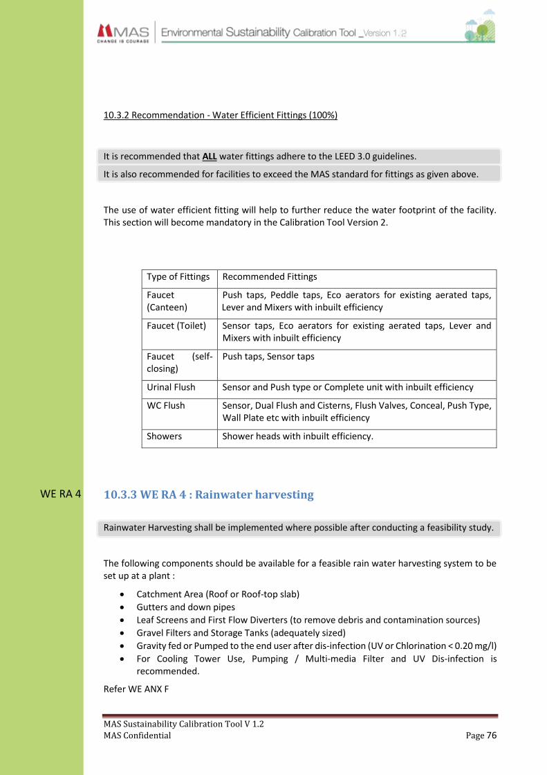
MAS Sustainability Calibration Tool V 1.2
MAS Confidential Page 76
WE RA 4
10.3.2 Recommendation - Water Efficient Fittings (100%)
It is recommended that ALL water fittings adhere to the LEED 3.0 guidelines.
It is also recommended for facilities to exceed the MAS standard for fittings as given above.
The use of water efficient fitting will help to further reduce the water footprint of the facility. This section will become mandatory in the Calibration Tool Version 2.
Type of Fittings Recommended Fittings
Faucet (Canteen)
Push taps, Peddle taps, Eco aerators for existing aerated taps, Lever and Mixers with inbuilt efficiency
Faucet (Toilet) Sensor taps, Eco aerators for existing aerated taps, Lever and Mixers with inbuilt efficiency
Faucet (self-closing)
Push taps, Sensor taps
Urinal Flush Sensor and Push type or Complete unit with inbuilt efficiency
WC Flush Sensor, Dual Flush and Cisterns, Flush Valves, Conceal, Push Type, Wall Plate etc with inbuilt efficiency
Showers Shower heads with inbuilt efficiency.
10.3.3 WE RA 4 : Rainwater harvesting
Rainwater Harvesting shall be implemented where possible after conducting a feasibility study.
The following components should be available for a feasible rain water harvesting system to be set up at a plant :
Catchment Area (Roof or Roof-top slab)
Gutters and down pipes
Leaf Screens and First Flow Diverters (to remove debris and contamination sources)
Gravel Filters and Storage Tanks (adequately sized)
Gravity fed or Pumped to the end user after dis-infection (UV or Chlorination < 0.20 mg/l)
For Cooling Tower Use, Pumping / Multi-media Filter and UV Dis-infection is recommended.
Refer WE ANX F

MAS Sustainability Calibration Tool V 1.2
MAS Confidential Page 77
WE RA 5
WE RA 6
10.3.4 WE RA 5 : Process Water Recovery
Attempts should be taken to recover and reuse process water.
Process water could be recovered from the following sources. Documented proof must be available with relevant persons.
Recovery of steam condensate for boiler feed water
Recovery of AC condensate
Recovery of process cooling water
Reuse cooling water
10.3.6 WE RA 7 : Drip irrigation for landscaping
Use re-cycled treated Waste water (sewage) or Harvested Rain Water for 50% of the total landscape area.
Following measures will ensure no potable water is used for landscaping:
Re-claimed Water Storage tank and feeding system (by gravity or flow actuated pump)
Selected Native Plant Species and zonally plumbing with a sub-flow meter.
LDPE (plastic) micro-irrigation tubing / Adjustable Drip Nozzles.
MAS Sustainability Calibration Tool V 1.2
MAS Confidential Page 78
WE MR 7
WE RA 7
WE MR 6
10.4 Water Resource Enhancement
Water resources can be further purified and replenished by using simple mechanisms.
10.4.1 WE RA 8 : Ground Water Recharge
Have in place ground water recharge mechanisms within the facility.
Storm water can be collected to a water collection pond for groundwater recharging.
Landscaping should be carried out to reduce soil erosion and increase water absorption. Consultancy can be obtained from recommended external parties.
Construct wetland system to purify (including treated sewage waste water) and sustain water tables. Consultancy can be obtained from recommended external parties.
Construct percolation pits & bore-wells.
10.5 Training
10.5.1 WE MR 6 : Training of Maintenance Personnel
Employees engaged in the water treatment (raw/waste) and plumbing process shall be trained on the proper usage and maintenance and basic testing of these systems.
The training can include efficient operation and maintenance of waste water treatment processes, efficient operation of Air-conditioning system, best practices and techniques on water-harvesting
All Employees
Periodic training for all staff members, on water conservation and the MAS water policy.
Special training sessions must also be conducted for janitorial and gardening staff.
This section is covered in the Culture Calibration Tool.
10.5.2 WE MR 7 : Plumbing drawing & water balance calculation
Have in place a plumbing layout drawing and water balance calculation.
The plumbing layout drawing must be update and displayed in the engineers office or pump house room. The facility can also do a periodic leak detection test.
Plant water balance calculation shall be available with the plant engineer / sustainability representative.

MAS Sustainability Calibration Tool V 1.2
MAS Confidential Page 79
WM MR 1
11.0 Waste Management (WM)
11.1.1 WM MR 1 : Centralised Waste Storage
A centralized waste storage area should be maintained for each factory / site.
11.1.1.1 Size of waste storage area
The size of the facility should be determined according to the amount of waste generated due to the normal operations of the factory and taking into account the frequency of waste collection / disposal. All waste items should be stored within the said facility and no waste material should be stored outside or at any other location.
11.1.1.2 Required infrastructure
The waste storage facility should be properly constructed having a roof to avoid rainwater contamination and effects of direct sun light. Effective spillage control measures such as a secondary container shall be in place for hazardous waste storage. The location of the facility should be determined according to access routes to be used by waste disposal vehicles.
11.1.1.3 Segregation at Waste storage facility
Waste collected at the centralized storage facility should be segregated by using a physical partition so that waste once stored will not get mixed. At a minimum the waste should be segregated as hazardous and non-hazardous waste. Non-hazardous waste should be further segregated according to the following types and taking into consideration the method of disposal.
1. Fabric 2. Paper / Cardboard 3. Plastic / Polythene 4. Bio-degradable 5. Glass / Metal
Signage should be used to identify the segregated waste at appropriate locations.
11.1.1.4 Hazardous waste storage
A separate room should be maintained for the storage of hazardous waste and appropriate warning signage should be used at the entrance. The hazardous waste storage facility shall have the following characteristics;
1. Built in a manner so that no seepage will occur due to a spill 2. Adequate secondary containment should be in place

MAS Sustainability Calibration Tool V 1.2
MAS Confidential Page 80
WM RA 1
WM RA 2
3. Adequate spill control kits should be placed nearby in case of an emergency
11.2 Segregation of waste
11.2.1 WM RA 1 : Source Segregation
Segregation of waste at source should be carried out at all possible locations within the factory / office premises. Segregation should be carried out according to the following waste types:
1. Fabric 2. Paper / Cardboard 3. Plastic / Polythene 4. Bio-degradable 5. Glass / Metal 6. Hazardous
If any type of source segregation is carried out, the colour codes mentioned in 11.2.2 should be used for the containers used for segregation.
11.2.2 WM RA 2 : Colour Code for Easy Identification of Waste Types
The following colour code should be adopted for the ease of identification of segregated waste. This colour code should be used on the walls, signage and any other items used for the storage of segregated waste.
Type of waste Colour
Bio-degradable Green
Fabric White
Paper / Cardboard Blue
Plastic / Polythene Orange
Glass Red
Metal / Mixed waste Brown
Hazardous waste Yellow
This section will be a mandatory requirement in the next version.
11.3 Waste disposal
The disposal of all types of waste should be carried out in accordance with the Environmental Protection License of the factory and the waste policy of MAS Holdings. The relevant factory will be responsible for the environmentally friendly disposal of all wastes generated from the factory. The factory is responsible for disposing of all wastes collected in accordance with section 11.3.4
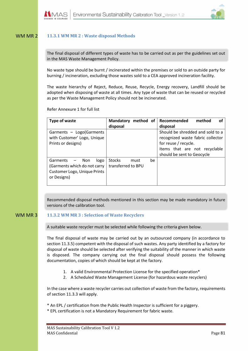
MAS Sustainability Calibration Tool V 1.2
MAS Confidential Page 81
WM MR 2
WM MR 3
11.3.1 WM MR 2 : Waste disposal Methods
The final disposal of different types of waste has to be carried out as per the guidelines set out in the MAS Waste Management Policy. No waste type should be burnt / incinerated within the premises or sold to an outside party for burning / incineration, excluding those wastes sold to a CEA approved incineration facility. The waste hierarchy of Reject, Reduce, Reuse, Recycle, Energy recovery, Landfill should be adopted when disposing of waste at all times. Any type of waste that can be reused or recycled as per the Waste Management Policy should not be incinerated. Refer Annexure 1 for full list
Type of waste Mandatory method of disposal
Recommended method of disposal
Garments – Logo(Garments with Customer' Logo, Unique Prints or designs)
Should be shredded and sold to a recognized waste fabric collector for reuse / recycle. Items that are not recyclable should be sent to Geocycle
Garments – Non logo (Garments which do not carry Customer Logo, Unique Prints or Designs)
Stocks must be transferred to BPU
Recommended disposal methods mentioned in this section may be made mandatory in future versions of the calibration tool.
11.3.2 WM MR 3 : Selection of Waste Recyclers
A suitable waste recycler must be selected while following the criteria given below. The final disposal of waste may be carried out by an outsourced company (in accordance to section 11.3.5) competent with the disposal of such wastes. Any party identified by a factory for disposal of waste should be selected after verifying the suitability of the manner in which waste is disposed. The company carrying out the final disposal should possess the following documentation, copies of which should be kept at the factory.
1. A valid Environmental Protection License for the specified operation* 2. A Scheduled Waste Management License (for hazardous waste recyclers)
In the case where a waste recycler carries out collection of waste from the factory, requirements of section 11.3.3 will apply. * An EPL / certification from the Public Health Inspector is sufficient for a piggery. * EPL certification is not a Mandatory Requirement for fabric waste.

MAS Sustainability Calibration Tool V 1.2
MAS Confidential Page 82
WM MR 4
WM MR 5
WM RA 3
11.3.3 WM MR 4 : Selection of Waste Collectors
A suitable waste collector must be selected while following the criteria given below. The collection and transportation of waste from the factory could be outsourced to a third party by either the factory or the recycler. In such an instant the third party identified for the collection of waste should possess the following documentation, copies of which should be kept at the factory.
1. Business registration / local authority approval to carry out the collection of waste 2. Sale records or documentation proof of how each type of waste is sold to a recycler 3. A Scheduled Waste Management License (for the transportation of hazardous
waste) Waste collectors are obligated to sell / transfer the collected waste to a qualified recycler. If the waste collector reuses or recycles any type of waste collected from the factory requirements of 11.3.2 will apply. In case a particular type of waste cannot be recycled or reused it should be sent for incineration to a CEA approved incineration facility.
Note: Please refer following link for printable/editable format for was disposal list. http://knet/sites/livinggreen/ESCalibrationTool/Forms/required_documentation
11.3.4 WM MR 5 : Agreements with Waste Collectors
The factory will sign an agreement with all waste collector/s who have been assigned to collect and transport waste out of the factory. The agreement shall include the following details;
1. The time period the agreement is valid for 2. Obligations of the factory and the waste collector (in accordance with section 11.3.3) 3. The types of waste the collector is responsible for collecting 4. The frequency of collection
11.3.5 WM RA 3 : Transportation of Waste
The transportation of waste out of the factory can be carried out using factory owned vehicles or vehicles of a contractor selected for this purpose. The vehicles used for transportation of waste should be specifically identified for this purpose and preferably should be a closed truck so that no spillage will occur during transportation.
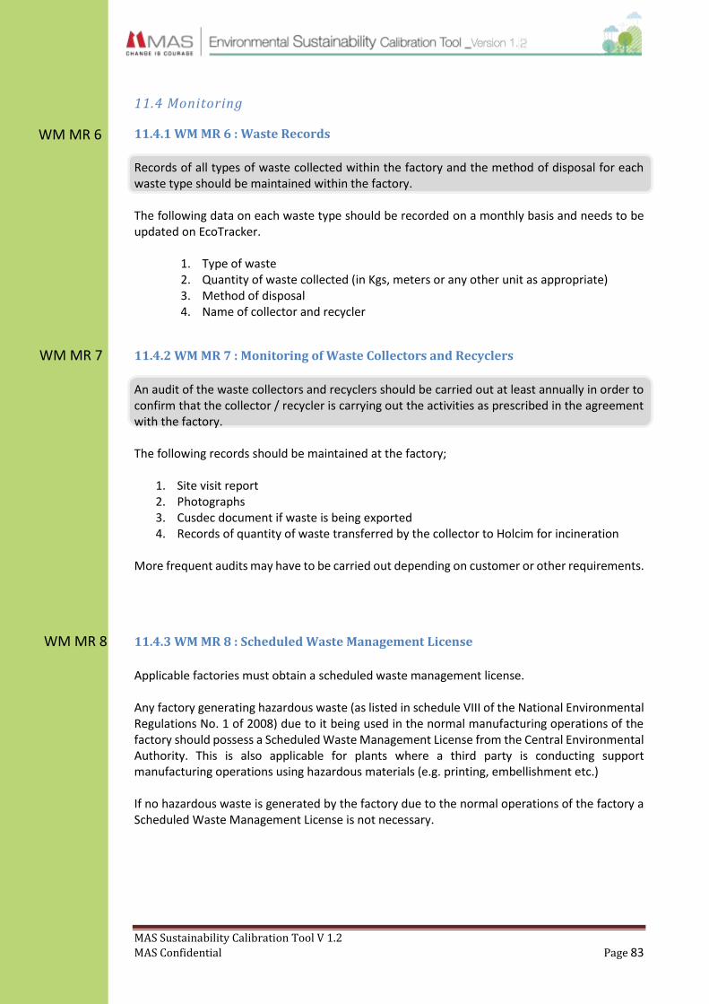
MAS Sustainability Calibration Tool V 1.2
MAS Confidential Page 83
WM MR 6
WM MR 7
WM MR 8
11.4 Monitoring
11.4.1 WM MR 6 : Waste Records
Records of all types of waste collected within the factory and the method of disposal for each waste type should be maintained within the factory. The following data on each waste type should be recorded on a monthly basis and needs to be updated on EcoTracker.
1. Type of waste 2. Quantity of waste collected (in Kgs, meters or any other unit as appropriate) 3. Method of disposal 4. Name of collector and recycler
11.4.2 WM MR 7 : Monitoring of Waste Collectors and Recyclers
An audit of the waste collectors and recyclers should be carried out at least annually in order to confirm that the collector / recycler is carrying out the activities as prescribed in the agreement with the factory. The following records should be maintained at the factory;
1. Site visit report 2. Photographs 3. Cusdec document if waste is being exported 4. Records of quantity of waste transferred by the collector to Holcim for incineration
More frequent audits may have to be carried out depending on customer or other requirements.
11.4.3 WM MR 8 : Scheduled Waste Management License
Applicable factories must obtain a scheduled waste management license. Any factory generating hazardous waste (as listed in schedule VIII of the National Environmental Regulations No. 1 of 2008) due to it being used in the normal manufacturing operations of the factory should possess a Scheduled Waste Management License from the Central Environmental Authority. This is also applicable for plants where a third party is conducting support manufacturing operations using hazardous materials (e.g. printing, embellishment etc.) If no hazardous waste is generated by the factory due to the normal operations of the factory a Scheduled Waste Management License is not necessary.

MAS Sustainability Calibration Tool V 1.2
MAS Confidential Page 84
WM MR 9
WM RA 4
WM MR 10
WM MR 11
11.5 Waste reduction programs
11.5.1 WM MR 9 : Waste Reduction Kaizen / project
A minimum of 1 Kaizen / project must be implemented with the objective of reducing the waste generated and/or to dispose of waste in a more environmentally friendly manner. It is recommended to conduct 5 kaizens annually. Records of the waste reduction programs should be maintained and should include;
1. Baseline 2. Target reduction level 3. Time period 4. Methods to be used 5. Actual reduction within the time period 6. Environmental benefit
11.5.3 WM RA 4 : Encourage Use of Environmentally Friendly Products
The management may take steps to encourage the use of recyclable / recycled / bio-degradable products within the factory and/or encourage the use of such products amongst its employees. Methods used for this purpose could include but not limited to;
1. Eliminating the use of non-recyclable products 2. Purchasing environmentally friendly products for the use in the factory 3. Subsidize environment friendly products for employees
11.6 Training
11.6.1 WM MR 10 : Training of Waste Handlers
Employees engaged in the waste disposal process (from generation to final disposal) shall be trained on the proper methods of waste disposal and on the use of personal protective equipment when handling hazardous waste. Records of such training programs should be kept at the factory. In addition one program must be conducted annually for all employees on waste related topic. This will be covered in more detail in the MAS_SCT_Culture Document.
11.7 Responsibility
11.7.1. WM MR 11 – Responsibility
The senior management shall appoint a competent employee who will be responsible for the management of waste within the factory and its disposal with any outside party. He/She will also be responsible for the maintenance of the records mentioned in earlier sections. Said person can also be included in the facility sustainability team.

MAS Sustainability Calibration Tool V 1.2
MAS Confidential Page 85
12.0 Emissions Management (EM)
12.1 Greenhouse Gas Emissions Management
12.1.1 Introduction
As per the Kyoto Protocol established in 1997 by the United Nations Framework Convention for
Climate Change (UNFCCC), a global treaty was accorded to reduce Greenhouse Gas (GHG)
emissions in order to prevent potentially drastic impacts on long term global climate trends.
Accordingly, time-bound emission reduction targets are to be achieved at regional and country
level to support this global goal.
The following is the list of gases mandated for measurement under the Kyoto Protocol
1. Carbon Dioxide (CO2)
2. Methane (CH4)
3. Nitrous Oxide (N2O)
4. Hydrofluorocarbons (HFCs)
5. Perfluorocarbons (PFCs)
6. Sulpher Hexafluoride (SF6)
Scope for GHG Measurement
The scope of measurement for greenhouse gases is mandated as per the six Kyoto gases
mentioned above. Further, reporting of GHG emissions are to be classified under scope 1,2 &3
as per level of control the operating facility has on such emissions.
Calculation Methodology
For calculation of GHG emissions the following guidelines are to be strictly adhered to and no
alternative methods are to be used for the purpose. The method shown below is to be used for
calculating emissions for fuel combustion & purchased utilities and Refrigerant use at Facilities.
Fuel combustion and Purchased utilities at Facilities
Activity data : electricity in kWh or fuel data in litres or kgs
Emissions factor : CO2 equivalent kg per kWh or litre or kg (Refer annexure EM ANX 01 for
applicable emission factors)
Refrigerant use at Facilities
Preferred Method: Mass Balance
The preferred method for emissions related to refrigerant use at facilities is the mass balance
method which requires taking account of actual refrigerant refill volume on a periodic or need
basis. Accordingly, the applicable formula is as follows:
GHG emissions (CO2e kg)= Activity data * Emission factor
GHG emissions (CO2e kg) = Refrigerants used (kg)* GWP

MAS Sustainability Calibration Tool V 1.2
MAS Confidential Page 86
EM MR 1
Nature and Scope of GHG Emissions
The following table provides the prescribed scope for measurement. While scope 3 emissions
measurement is not mandatory, please consider this as a recommended course of action for
good practice.
Nature of emissions Scope Reporting Status
Use of fossil fuels for stationary combustion within processes controlled and owned by the facility: Diesel/LPG/Kerosene/HFO (Control of process includes machinery and equipment hired/owned equally.
1 Mandatory
On-site combustion of waste or other processes not related to production
1 Mandatory
Diesel/Petrol/LPG used for company owned vehicles
1 Mandatory
Refrigerants from AC and freezer units which are not ODGs (Please refer annexure 02 for GHG emitting refrigerants)
1 Mandatory
Purchased electricity from the National Grid 2 Mandatory
Non-renewable energy purchased for use in the facility (steam/heat/other)
2 Mandatory
12.1.2 EM MR 1 : Primary data recording
Make sure the below mentioned items (quantity) are recorded and uploaded on eco tracker.
Purchased electricity
Fuel (Diesel/Kerosene/LPG/HFO)
Fuel : Company owned Vehicles
Purchased non-renewable energy (Steam/heat)
Purchased refrigerants

MAS Sustainability Calibration Tool V 1.2
MAS Confidential Page 87
12.2 Refrigerant Management
12.2.1 Introduction
Inventory of ODGs
An inventory of ODG emitting refrigerants is to be compiled by each operating facility as per the
guidelines set by the Montreal Protocol which was ratified by the Government of Sri Lanka. A
list ODGs is provided in annexure 03 for reference and completion of the same.
In order to establish an ODG baseline for reduction and phase-out facilities can calculate their
ODG impact as per the methods explained in the following section.
Calculation Methodology
Preferred Method: Mass Balance
The preferred method for emissions related to refrigerant use at facilities is the mass balance
method which requires taking account of actual refrigerant refill volume on a periodic or need
basis. Accordingly, the applicable formula is as follows:
Secondary Method: Annual Leakage Rate
In the event that the plant does not have access to actual refrigerant data, the following method
could be used for completeness of reporting. However, this method is to be used only as a “last
resort” and not as an alternative to the mass balance method.
For chillers as per IPCC guidelines
For packaged units as per IPCC guidelines
For packaged units as per IPCC guidelines
GHG emissions (CO2e kg) = Capacity of unit*15% * GWP
GHG emissions (CO2e kg) = Refrigerants used (kg)* GWP
GHG emissions (CO2e kg) = Capacity of unit*5% * GWP

MAS Sustainability Calibration Tool V 1.2
MAS Confidential Page 88
EM MR 2
ODGs banned by the Government of Sri Lanka
As per the guidelines set by the Government of Sri Lanka the following gases are banned.
Accordingly, the use of such is a violation of the emission calibration standards. Full list available
in EM ANX C.
Planned Strategy for Phase out of ODGs
In accordance with the expectations set under the Montreal Protocol, all new units purchased
within MAS Holdings with effect from January 2014 should not use ODGs. Therefore, the
emission calibration standards will aim to make MAS Holdings’ refrigerant use ODG-free by 2024.
This directive is subject to change depending on any forthcoming local or/and international
regulations.
12.2.1 EM MR 2 : Refrigerants Usage
The purchases of new equipment using CFC refrigerants are banned (refer table: Banned ODG
with effect from Oct 2003).
Existing equipment using CFC refrigerants purchased prior to Jan 2000 must be phased out and
converted to CFC free refrigerants by 2024. (Refer Annexure EM ANX 3)
The facility must have an updated list of all refrigerants used.
Table : Ozone Depleting Gases Banned
Code Symbol Substance
CFC -11 CFCl3 Trichlorofluoromethane
CFC- 12 CF2Cl2 Dichlorodifluoromethane
CFC- 113 C2F3Cl2 Trichlorofluoroethane
CFC- 114 C2F4Cl2 Dichlorodifluromethane
CFC- 115 C2F5Cl Chloropentafluroethane
Halon- 1211 CF2BrCl Bromochlorodifluoromethane
Halon- 1301 CF2Br Bromotrifluoromethane
Halon- 2402 CF4Br2 Dibromotetrafluroethane
CFC- 13 CF3Cl Chlorotrifluromethane
CFC- 111 C2FCl5 Pentachlorofluroethane
CFC- 112 C2F2Cl4 Tetrachlorodifluroethane
CFC- 211 33FCl7 Heptachlorofluropropane
CFC- 212 C3F2Cl6 Hexachlorodifluropropane
CFC- 213 C3F3Cl5 Pentachlorotrifluropropane
CFC- 214 C3F4Cl4 Tetrachlorotetrafluroprone
CFC- 215 C3F5Cl3 Trichloropentafluropropane
CFC- 216 C3F6Cl2 Dichlorohexafluropropane
CFC- 217 C3F7Cl Chloroheptafluropropane
Source: Gazette Extraordinary No 850/4 of Dec 1994

MAS Sustainability Calibration Tool V 1.2
MAS Confidential Page 89
EM MR 3
EM RA 1
Air conditioner units
AC Type Refrigerant
Type
Annual recharge quantity of refrigerants (kg)
LG 9000 BTU R-22 0.5 kg
Refrigerators, Freezers & water dispensers
Refrigerator
type
Refrigerant
Type
Annual recharge quantity of refrigerants (kg)
Freezer R-134a 0 kg
12.3 Stack emissions
12.3.1 EM MR 3 : Annual Testing of Flue Gas
All facilities are expected to conduct a stack emissions test on an annual basis.
Stack emission tests must be conducted for boilers, generators & incinerators. Please refer
annexure EM ANX 4 for accredited third parties who could provide the said services. Stack height
measurements must also be available with the factory Engineer.
12.4 EM RA 1 : Scope 3 Emissions
Following sources of scope 3 emissions are recommended to be reported for good practice and
identification and influence of emission sources not within the direct control of the organization.
Nature of emissions Methodology for measurement
Stationary combustion: Use of fossil fuels within processes but not controlled or owned by the facility: Diesel/LPG/Kerosene/HFO
Please refer section 11.1.3
Mobile combustion: Diesel/Petrol/LPG used in hired vehicles for raw material, finished goods and employee commute. (Travel includes both surface and air)
Please refer section 11.1.3

MAS Sustainability Calibration Tool V 1.2
MAS Confidential Page 90
EM RA 2
EM RA 3
EM RA 4
12.5 EM RA 2 : Guidelines for Stack Emissions
Facilities are recommended to meet the interim standards and guidelines set by the Central
Environmental Authority (CEA) on flue gas emissions and stack height.
Please refer annexure EM ANX 05.
12.6 EM RA 3 : Emission Reduction Initiatives
The following reduction opportunities are recommended. At least one initiative per year.
Identification of efficiency measures to reduce electricity and stationary energy use.
Generation or/and purchase of renewable energy (Solar, hydro, biomass and wind)
Generation or/and purchase of waste to energy sources such as biogas
Use of hybrid and electric vehicles for owned-fleet at facility level
Implementation of owned and/or community-based afforestation projects for offset of
emissions impact.
12.7 EM RA 4 : Biomass Supply
12.7.1. Use of Biomass Residue
Facilities which are currently using or intending to use biomass in their in-house stationary
combustion are encouraged to use biomass residue.
Following is the list of recommended composition of biomass residue.
Saw dust/saw dust briquettes
Paddy husk/paddy husk briquettes
Trimmings (Rubber, Cashew, Cinnamon, Pine, Acacia)
Residue approved by respective authorities such as the Forest Department and State
Timber Corporation
12.7.2. Use of Fuel wood
Facilities which are currently using or intending to use biomass in their in-house stationary
combustion are expected to consider using the following in their biomass composition:
- Gliricidia
- Caliandra
12.7.3 Maintaining a record of biomass supply

MAS Sustainability Calibration Tool V 1.2
MAS Confidential Page 91
EM RA 5
Operating facilities are requested to maintain a consistent and updated supplier register for each
batch of biomass.
DATE BATCH NO
SUPPLIER
VEHICLE NUMBER
CLEARANCE DETAILS
TYPE
QUANTITY
REGION
REMARKS
12.7.4 Facilities are recommended to keep a checklist of biomass used with respect to the hours
run.
NO Date Running Hours Biomass Used (kg) Remarks
11.7.5 Facilities’ database with types and vendors will be subject to spot checks throughout the
year which will include the following for verification:
- Sourcing sites will be checked against plants’ database
- Spot samples will be checked for consistency in composition highlighted above
12.8 EM RA 5 : Large Scale and Long-Term Supply Partners for Biomass
Plants with an existing or a future biomass requirement are expected to maintain at least 20% of
its total supply through long term and large scale suppliers.
This is applicable for facilities that use 10 tons of biomass or more per day.
To qualify as a long term and large scale supplier the following conditions must be met:
- Meet at least 10% of the total daily requirement of the plant
- Provide biomass types recommended in section 11.7 of this document
- Sign an agreement to provide disclosure into vendor’s supply chain and support spot audits.
- Provide a stable supply and enter into an agreement to that effect for at least a year.

MAS Sustainability Calibration Tool V 1.2
MAS Confidential Page 92
STE RA 1
13.0 Building Site & Envelop (STE)
13.1 STE RA 1 : Landscape Management Plan
A landscape management plan for the facility covering the following details (minimum) should be available.
a. Landscape map with storm water discharge lines/points b. Quantity of water used for irrigation c. List of landscape equipment
The landscape management plan should be prepared so as to reduce impervious cover, promote infiltration, capture and treat storm water run-off and to limit all site disturbances beyond the building perimeter, walkways and roadway curbs. It is recommended to use percolation pits and sedimentation traps with proper maintenance. Consider bird safe landscaping, façade treatment and glazed surfaces.
A system should be implemented to calculate the quantity of water used for gardening. If there is no separate water meter for this purpose a log sheet should be maintained indicating the time, duration of watering, dates and locations. This data can be used to estimate the quantity of water used for gardening each month. This is mandatory for facilities that use potable water for irrigation and recommended for those who use recycled water.
The list of equipment should also specify the frequency of usage of the equipment and the types and quantity of the fuels used.

MAS Sustainability Calibration Tool V 1.2
MAS Confidential Page 93
STE RA 2 13.2 STE RA 2 : Heat Gain & Thermal Envelop
A thermal audit of all air conditioned buildings by using an IR camera should be carried out at
least once a year.
Abnormal heat/thermal spots should be identified by using an IR Thermal Camera. Windows, doors, walls etc. that are exposed to direct sunlight should be treated accordingly in order to reduce solar radiation into the facility.
Thermal heat gain from roofs can be reduced by insulating the roof or planting vegetation on the top of flat roofs.
Iinfiltration should be reduced via sealing cracks in a building's envelope, and for new construction or major renovations, by installing continuous air retarders.
Roof: Material of roofing sheets should have at least SRI78 or SRI29 depending on the slope of the roof, a green roof or a combination of both. Please see STE ANX A & B for more details of insulation types and their parameters.
Non-roof: Provide shading by introducing a tree canopy and have open grid paving. It is recommended to use materials with at least SRI29 rating or more.
Microclimate: A layout plan for existing paving, roads, courtyards etc. should be available. It is recommended for more than 50% of such areas should be shaded.
Shading: Windows exposed to direct sunlight (East-west oriented) should be adequately
shaded from the outside.
One or more of the following recommendations could be implemented as appropriate.
a. Shade to be provided through the of recesses in the external envelope of the building b. Shade to be provided by static or moveable external blinds or louvers c. Transient shading to be provided by the orientation of the building on one or more of
its external walls d. Permanent or transient shading to be provided by the surrounding buildings, screens or
vegetation. e. Shading of roofs by rolling reflective canvass, earthen pots, vegetation etc.
MAS Sustainability Calibration Tool V 1.2
MAS Confidential Page 94
STE RA 4
STE RA 3 13.3 STE RA 3 : Asbestos Removal
It is recommended not to use asbestos as construction material when building new roofs.
It is also recommended that existing asbestos roofing material be phased out gradually.
13.4 STE RA 4 : Site Maintenance
A landscape map with tree location and list of species should be available.
Consider using native species in new garden projects.
As built drawings of the factory, a building material checklist and schedules should be available.
It is recommended to have a Certificate of Conformity issued by the Factory Inspection
Engineer.
Have the following checklists / schedules in place;
Cleaning maintenance
Garden maintenance
Onsite composting and organic fertilization

MAS Sustainability Calibration Tool V 1.2
MAS Confidential Page 95
Facility should form a Chemical Management Team to coordinate the development and
implementation of the facility Chemical Management System
CM MR 1
14.0 Chemical Management (CM)
Many chemicals, dyes and raw materials are used in manufacturing processes. However, their
toxicity to human and to the environment is not always fully known. The MAS Chemical
Management Work Stream (CMWS) was initiated in 2013 with the intention of making ‘MAS and
its products free of toxic chemicals by 2020’. We will ensure the safety of our people, our
consumers and our environment through proactively understanding and prudently selecting
every chemical and raw material used within MAS.
The ‘Chemical Management’ forms a key part of our work stream. Effective chemical
management within the facility will ensure concrete benefits such as reducing costs and
environmental impact, becoming more competitive and improving worker health and safety.
14.1 Chemical Management System
14.1.1 CM MR 1: Chemical Management Team
A team approach to chemical management in a facility has been found to be the most effective strategy for long term planning and implementation. A team creates institutional memory, and the success of the team’s work continues even if one member leaves the facility. Also, a team representing all aspects of chemical use in the facility will develop a chemical management system that represents the entire facility, and helps to coordinate common responsibilities across departments.
Key stakeholders for your team; • Senior manager (GM/HRM/Dye house manager) • Department representatives (Dye house, Printing, QA lab, Maintenance, HR and
Finance) • Purchasing officer • Safety officer/ Compliance (Restricted Substances List/RSL) point person
• Representatives from chemical handling
Team meetings should be conducted (refer the following table) and meeting minutes must be
documented. A ‘Champion’ will be required to drive these initiatives.
MAS Sustainability Calibration Tool V 1.2
MAS Confidential Page 96
The facility should adopt the MAS Chemical Management Policy
The facility should have a written chemical management plan
CM MR 2
CM RA 1
Table : Meeting frequency
Type of the business Meeting frequency
Cut and sew Quarterly
Dyeing, Printing Monthly
Note: Can be combined with any other committee/team
14.1.2 CM MR 2: Chemical Management Policy
The MAS Chemical Management Policy will address the following areas;
Chemical Purchasing Procedure
Chemical Handling and Use Procedure
Chemical Storage Procedure
Chemical Labeling
Note: For the Calibration Tool Version 1.2 facilities must adopt the MAS Chemical Procedure or
show progress of adoption. The MAS Chemical Management Policy will be shared with SBU’s
within the year.
14.1.3 CM RA 1: Chemical Management Plan
It is important that the facility set new targets and areas for action in order to make further
improvements in the management of hazardous chemicals. The facility can incorporate
programs in place to phase out the intentional use of the Zero Discharge of Hazardous Chemical
(ZDHC) priority chemical groups.

MAS Sustainability Calibration Tool V 1.2
MAS Confidential Page 97
The facility should maintain a Chemical Inventory list
CM MR 3
14.2 Information of chemicals/dyes
14.2.1 CM MR 3: Chemical Inventory
14.2.1.1 Prepare a Chemical Inventory
A Chemical Inventory is a comprehensive list of chemicals/dyes used in a facility including;
Dye house
Printing
Production
Maintenance (thinners, coolants, machine oil, etc.)
Effluent Treatment Plant
Janitorial services (soap, detergents, etc.)
Laboratory, etc.
This enables facilities to easily respond to request on any use of hazardous chemicals for
production.
Information of all chemicals used in the facility should be filled in the ‘Chemical Inventory Form’
developed by the MAS Chemical Management Work Stream.
Note: Facility must complete the chemical inventory by 2 months prior to the assessment date
and send it back to the MAS Chemical Management Work Stream to carry out the ‘Hazard
Assessment’.
Note: Please refer following link for printable/editable format.
http://knet/sites/livinggreen/ESCalibrationTool/Forms/required_documentation
Figure : Chemical Inventory Form
MAS Sustainability Calibration Tool V 1.2
MAS Confidential Page 98
The facility should collect additional information on dyes/chemicals including;
Technical Data Sheet (TDS)
Certificate of Analysis (CoA)
CM RA 2
14.2.1.2 Update the Chemical Inventory
Maintaining a chemical inventory should be a continuous process. Therefore, the chemical
inventory should be revised/updated due to,
Addition of new chemicals/dyes, new suppliers, etc.
Deletions
The MAS Chemical Management Work Stream will review the chemical inventory biannually.
Facility should clearly highlight the above changes (ex: use two color codes for addition and
deletions) and the quantity in the chemical inventory for the existing chemicals/dyes should also
be updated biannually.
14.2.1.3 Maintain MSDS
Material Safety Data Sheet (MSDS) or Safety Data Sheet (SDS) of all chemicals should be less than of 3 year old. The facility must communicate the requirement to chemical suppliers in order to obtain the most updated MSDS. If the existing MSDS does not meet the criteria, the facility must obtain a verification from the supplier to confirm that it is the most up-to-date version.
Although MSDS can vary in format, the facility should require their chemical suppliers to provide MSDS similar to the preferred examples in the CM ANX A. Restricted substances issues could be prevented when MSDS equipped with good information.
Each department of the facility should maintain MSDSs in a file for all chemicals/dyes used by them.
14.2.3 CM RA 2: Additional Information of Dyes/Chemicals
14.2.3.1 Technical Data Sheet (TDS)
Technical Data Sheet (TDS) or Technical Information (TI) sheet gives important information such as product description (application field, storage info, shelf life, etc.) and chemical nature (claims like APEO-free, metal-free, etc.).
The facility should collect TDSs for all chemicals from chemical suppliers and document them.
Note: TDS is not available for dyes

MAS Sustainability Calibration Tool V 1.2
MAS Confidential Page 99
The facility should maintain a Chemical Disposal List (MR)
CM MR 4
14.2.3.2 Certificate of Analysis
The Certificate of Analysis is a document generated for each run or batch of a product shipped. This may contain a list and percent composition of active ingredients, and results of analytical tests that were performed on the product, such as tests for contaminants (e.g., lead, cadmium).
Dye houses and QA (Quality Assurance) labs should collect this document for all chemicals/dyes used in their processes. Electronic version of this document should be available with the relevant person in the department.
Refer CM ANX B for more information.
14.2.5 CM MR 4: Chemical Disposal List
Completing the chemical disposal list will help the facility to identify chemical management problems or cleanout issues that need immediate attention or action (e.g., situations that might pose health and safety concerns to workers and staff, such as potential explosions or fires). It also helps to rank and prioritize departments and areas of the facility needing cleanout. Using this list, the facility could estimate the types and quantities of chemicals for removal in the cleanout. The facility can also identify activities that need the expertise of a qualified professional (e.g., removing and disposing of chemicals) when using a chemical disposal list.
Chemicals that are no longer being used, outdated, in poor condition, or otherwise in line for disposal should be included in this list. The facility should incorporate the following format to create the chemical disposal list.
Table 1: Chemical disposal list (Example)
Storage date
Product name
Information on
ingredients
CAS numbe
r
Expiry date
Estimated amount
Task owner
Action plan
Date of disposal
14/02/ 2013
RUCOGEN FWK
Nonionic surfactants (25-50%)
N/A 24/04/2014
20 kg
Propan-2-ol (1-5%)
67-63-0

MAS Sustainability Calibration Tool V 1.2
MAS Confidential Page 100
The facility should gather positive lists from chemical suppliers
Facility should test both incoming water and raw effluent against the ZDHC 11 priority chemical
groups
CM RA 3
CM MR 5
14.3 Restricted Substances Compliance
14.3.1 CM RA 3: Positive List
Positive List (Refer CM ANX C) is a signed and dated declaration made by chemical suppliers which confirm that the formulations supplied to the facility are compliant with the ZDHC MRSL (e.g. no intentional ingredients of any ZDHC 11 priority chemical groups or as impurities above the limit specified in the MRSL). The facility should communicate this requirement to all chemical suppliers who are supplying
chemicals (all chemicals including dye house, effluent treatment plant/ETP, quality assurance
and maintenance and bulk chemicals) regarding this requirement in order to ensure their
commitment on the ZDHC targets. The facility should check whether any of these declarations
are renewed at least annually. This would enable facility to choose suppliers based on their
environmental performance.
Note: This requirement will be mandated in Calibration Tool Version 2. The facility should be
able to produce proof (ex: e-mail) of communications with suppliers.
14.3.2 CM MR 5: Water Testing against the ZDHC 11 Priority Chemical
Groups
Facility should test both incoming water and raw effluent against the ZDHC 11 priority
chemical groups. Please refer the Table 3 for the testing frequency.
Table : Water testing frequency
Type of the business Testing frequency
Fabrics Alliance Bi-annually
Silueta and Linea Intimo Annually
Wet process entities Annually (Exempted for Version 1.2)
Cut and Sew plants without wet processing Exempted
Testing incoming water will confirm whether the facility’s incoming water already contains any of the 11 ZDHC chemical groups. If it does, then it could be that the plant is using clean chemicals, but the facility incoming water is not clean. Raw effluent is the wastewater before conducting any treatment. Testing raw effluent identifies which of the 11 ZDHC chemical groups are being used in production.

MAS Sustainability Calibration Tool V 1.2
MAS Confidential Page 101
The facility should have an action plan in the case of non-compliance with the ZDHC MRSL
CM RA 4
Water samples should be tested against the following priority chemical groups.
1. Alkylphenol ethoxylates and Alkylphenols (APEOs and APs) 2. Phthalates 3. Brominated and chlorinated flame retardants 4. Azo dyes 5. Organotin compounds 6. Perfluorinated chemicals (PFCs) 7. Chlorobenzenes 8. Chlorinated solvents 9. Chlorophenols 10. Short-chain chlorinated paraffins (SCCPs) 11. Heavy metals: Cadmium, Lead, Mercury and Chromium (VI)
These testing must be carried out by Bureau Veritas, Sri Lanka and the Compliance Point Person should share the results only with the MAS Chemical Management Work Stream upon request. Refer the following table for testing frequency.
Note: This requirement will be mandated for Wet Processing facilities from Calibration Tool Version 2.0 onwards.
14.3.3 CM RA 4: Action Plan in case of non-compliance
There are instances of non-compliance of chemicals/dyes due to intentional addition of
ingredients specified in the ZDHC 11 priority chemical groups or as impurities above the limit
specified in the ZDHC MRSL. In such cases, facility should build business relationships with their
suppliers to respond to such situations and overcome non-compliance.
Facility should be able to provide a copy of the corrective action process if there is any non-
conformance in the supply of the chemicals found by the facility.
Note: The MAS Chemical Management Work Stream will guide the facility to evaluate safer
alternative substances in the case of non-compliance with the ZDHC MRSL.

MAS Sustainability Calibration Tool V 1.2
MAS Confidential Page 102
The facility should ensure the chemicals stored, labelled, handled and used in a proper
manner including;
Provide personal protective equipment
Containers must be capped and sealed
Segregation according to hazards
Storage of chemical waste
HMIS Rating
PPE Index
CM MR 6 14.4 CM MR 6: Chemical Storage, Labelling, Handling and Use
14.4.1 Availability of Personal Protective Equipment (PPE)
It is the responsibility of the facility to provide separate personal protective equipment (PPE) kits
for people who handle chemicals and they should be trained on the use of PPE. Personal
protective equipment must use properly when handling chemicals.
14.4.2 Storage of chemical containers when not in use
All chemical containers should be kept closed tightly when not being used. Facility should also
ensure that the excess chemicals are stored back in the main barrel soon after the addition
especially if jugs are used to transfer chemicals from the main drum/barrel. This is useful to
maintain the quality of chemicals.
14.4.3 Segregation according to Hazards
Chemicals should be stored according to chemically compatible families (chemical class/ reactive group). Compatibility on shelves should be vertical as well as horizontal. Storage recommendations given in the MSDS of the chemical should be followed.
14.4.4 Storage of Chemical Waste
Chemicals listed in the ‘Chemical disposal list’ under the section 14.2.5 should be stored
separately until a proper disposal method is determined. Follow the guidelines specified in the
section 14.4.4 when storing these chemicals.
14.4.5 HMIS Rating
A Hazardous Material Identification System (HMIS) is a numerical hazard rating that incorporates
the use of labels with color developed by the American Coatings Association as a compliance aid
for the OSHA Hazard Communication Standard.
The HMIS rating is found in the MSDS of the chemical. HMIS labels must be displayed to all
chemicals/dyes in the chemical storage area and the place of use. Refer CM ANX D.
14.4.6 PPE Index
The PPE Index must be posted in the chemical storage area and the place of use. Refer CM ANX
D.
MAS Sustainability Calibration Tool V 1.2
MAS Confidential Page 103
The facility should
Monitor and document its chemical usage
Report the consumption of ‘Red’ and ‘Amber’ chemicals
Secondary containment should be available at all locations where chemicals are stored
CM RA 5
CM MR 7
14.4.7 CM RA 5: Secondary Containment
Facility should provide sufficient secondary containment for containers of any chemicals,
hazardous materials, solvents, etc. in the workplace. Capacity of the secondary containment
should be minimum of 110% of the primary container.
This requirement will be mandated in Calibration Tool Version 2.
14.5 CM MR 7: Consumption Monitoring
The facility should document the monthly consumption of all chemicals. The electronic version
of the monthly consumption report should be available with the purchasing officer.
The MAS Chemical Management Work Stream (CMWS) will carry out the ‘Hazard Assessment’ after the chemical inventory is submitted by the facility. This assessment will include a close and thorough inspection of the chemicals used within the business, cross reference them against our own MAS MRSL (Manufacturing Restricted Substances List) and classify them as either Red, Amber or Green.
Monthly consumption of the ‘Red’ and ‘Amber’ classified chemicals should be reported to the MAS CMWS by the first week of following month.

MAS Sustainability Calibration Tool V 1.2
MAS Confidential Page 104
Employees directly exposed to chemicals should be trained annually
Empty chemical containers should be washed before being disposed from the factory premises
(MR)
CM MR 8
CM MR 9
14.6 CM MR 8: Training
Training topics should include and may not be limited to the following:
Safe handling, transportation, use and storing of chemicals
Chemical hazards
Toxicities of chemicals
Training on MSDS handling
Spillage prevention practices
Spill response plan
All trainings need to be documented (Signature sheets, photographs, training materials, etc.
should be available).
14.7 CM MR 9: Chemical Barrel Washing
All chemical cans and barrels need to be washed in house before being sold to a waste vendor.
100% of the washing effluent should be diverted to an effluent treatment plant.
The chemical containers refer to any container that was used to store / transport any
hazardous substances into the factory. These could be any type of barrels and cans used for
dyes, dyes, chemicals, printing ink, glue etc.
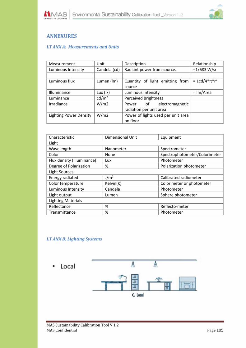
MAS Sustainability Calibration Tool V 1.2
MAS Confidential Page 105
ANNEXURES
LT ANX A: Measurements and Units
Measurement Unit Description Relationship
Luminous Intensity Candela (cd) Radiant power from source. =1/683 W/sr
Luminous flux Lumen (lm) Quantity of light emitting from source
= 1cd/4*π*r2
Illuminance Lux (lx) Luminous Intensity = lm/Area
Luminance cd/m2 Perceived Brightness
Irradiance W/m2 Power of electromagnetic radiation per unit area
Lighting Power Density W/m2 Power of lights used per unit area on floor
Characteristic Dimensional Unit Equipment
Light
Wavelength Nanometer Spectrometer
Color None Spectrophotometer/Colorimeter
Flux density (Illuminance) Lux Photometer
Degree of Polarization % Polarization photometer
Light Sources
Energy radiated J/m2 Calibrated radiometer
Color temperature Kelvin(K) Colorimeter or photometer
Luminous Intensity Candela Photometer
Light output Lumen Sphere photometer
Lighting Materials
Reflectance % Reflecto-meter
Transmittance % Photometer
LT ANX B: Lighting Systems
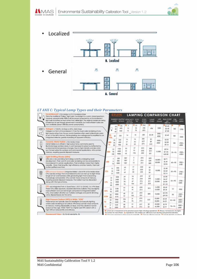
MAS Sustainability Calibration Tool V 1.2
MAS Confidential Page 106
LT ANX C: Typical Lamp Types and their Parameters
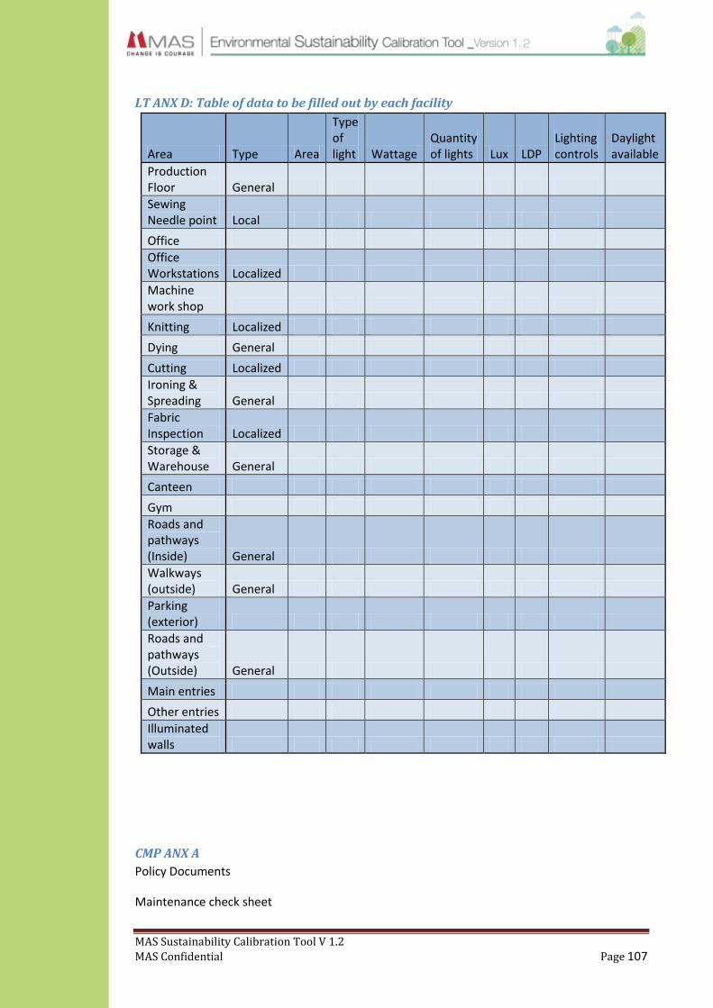
MAS Sustainability Calibration Tool V 1.2
MAS Confidential Page 107
LT ANX D: Table of data to be filled out by each facility
Area Type Area
Type of light Wattage
Quantity of lights Lux LDP
Lighting controls
Daylight available
Production Floor General
Sewing Needle point Local
Office
Office Workstations Localized
Machine work shop
Knitting Localized
Dying General
Cutting Localized
Ironing & Spreading General
Fabric Inspection Localized
Storage & Warehouse General
Canteen
Gym
Roads and pathways (Inside) General
Walkways (outside) General
Parking (exterior)
Roads and pathways (Outside) General
Main entries
Other entries
Illuminated walls
CMP ANX A
Policy Documents
Maintenance check sheet
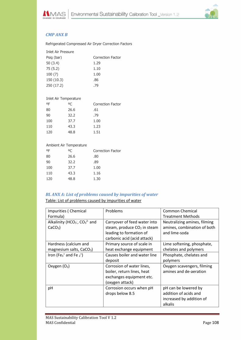
MAS Sustainability Calibration Tool V 1.2
MAS Confidential Page 108
CMP ANX B
Refrigerated Compressed Air Dryer Correction Factors
Inlet Air Pressure
Psig (bar) Correction Factor
50 (3.4) 1.29
75 (5.2) 1.10
100 (7) 1.00
150 (10.3) .86
250 (17.2) .79
Inlet Air Temperature
ºF ºC Correction Factor
80 26.6 .61
90 32.2 .79
100 37.7 1.00
110 43.3 1.23
120 48.8 1.51
Ambient Air Temperature
ºF ºC Correction Factor
80 26.6 .80
90 32.2 .89
100 37.7 1.00
110 43.3 1.16
120 48.8 1.30
BL ANX A: List of problems caused by impurities of water
Table: List of problems caused by impurities of water
Impurities ( Chemical Formula)
Problems Common Chemical Treatment Methods
Alkalinity (HCO3-, CO3
2- and CaCO3)
Carryover of feed water into steam, produce CO2 in steam leading to formation of carbonic acid (acid attack)
Neutralizing amines, filming amines, combination of both and lime-soda
Hardness (calcium and magnesium salts, CaCO3)
Primary source of scale in heat exchange equipment
Lime softening, phosphate, chelates and polymers
Iron (Fe3+ and Fe 2+) Causes boiler and water line
deposit Phosphate, chelates and polymers
Oxygen (O2) Corrosion of water lines, boiler, return lines, heat exchanges equipment etc. (oxygen attack)
Oxygen scavengers, filming amines and de-aeration
pH Corrosion occurs when pH drops below 8.5
pH can be lowered by addition of acids and increased by addition of alkalis

MAS Sustainability Calibration Tool V 1.2
MAS Confidential Page 109
Hydrogen Sulfide (H2S) Corrosion Chlorination
Silica (SiO2) Scale in boilers and cooling water systems
Lime Softening
Source : fact sheet – Boiler Chemicals 101 :North Carolina Department of Environment and Natural Resources (NCDENR)
IEQ ANX A
Table : Maximum Limits for indoor Particulate Matter (PM) volume
SCHEDULE
Pollutant Averaging time
Maximum Permissible Level
Method of measurement
µgm-3 ppm
Particulate Matter – Aerodynamic diameter is less than 10µm in size (PM10)
Annual 50 - High-volume sampling and Gravimetric or Beta Attenuation 24 Hours 100 -
Particulate Matter – Aerodynamic diameter is less than 2.5µm in size (PM2.5)
Annual 25 - High-volume sampling and Gravimetric or Beta Attenuation 24 Hours 50 -
Source: National Environmental (Ambient Air Quality) Regulations, 1994, published in Gazette Extraordinary, for particulate matter.
IEQ ANX B
Table : MERV filter efficiencies
MERV Rating 0.3-1.0 Microns 1.0-3.0 Microns 3.0-10.0 Microns
Dust Spot Efficiency
1 <20% <20%
2 <20% <20%
3 <20% <20%
4 <20% <20%
5 20-35% <20%
6 35-50% <20%
7 50-70% 25-30%
8 >70% 30-35%
9 <50% >85% 40-45%
10 50-65% >85% 50-55%
11 65-80% >85% 60-65%
12 <80% >90% 70-75%
13 <75% <90% >90% 89-90%
14 75-85% <90% >90% 90-95%
15 85-95% <90% >90% >95%
16 <95% <95% >95% N/A

MAS Sustainability Calibration Tool V 1.2
MAS Confidential Page 110
17 >99.9%
18 >99.9%
19 >99.9%
20 >99.9%
Reference: Allfilters.com & ASHRAE 52.2
IEQ ANX C
Table: Noise Level

MAS Sustainability Calibration Tool V 1.2
MAS Confidential Page 111
IEQ ANX D: Additional Information
Air Exchange Rates
The following air change rates should be followed in any typical factory setup. These values have
been derived from ASHRAE 62.1 to better suite factory working conditions.
Typical Location Air Changes per Hour
1 Factory sewing floor 4-6
2 Kitchen 40
3 Operation Theatres 25-30
4 Workshop / Laundry 16
5 Normal / office room 2-4
6 Public wash rooms 16
7 Office wash rooms 6-12
IEQ ANX E: Ventilation Rate Procedure (VRP) – ASHRAE 62.1
Fresh air should be calculated as per the Ventilation Rate Procedure (VRP) mentioned in ASHRAE 62.1. The VRP is a prescriptive procedure in which outdoor air intake rates are predetermined for various space types (occupancy categories) based on contaminant sources and source strengths. The rates are intended to dilute and exhaust odorous bio effluents from occupants and odorous and sensory irritant contaminants from other sources common to that type of space. The VRP is based on typical spaces, those with contaminant source strengths commonly found in the listed category, and based on achieving reasonable levels of adapted occupant satisfaction with space air quality.

MAS Sustainability Calibration Tool V 1.2
MAS Confidential Page 112
IEQ ANX F: Thermal Comfort
Thermal comfort is a condition that expresses satisfaction to the environment around. This has
been evaluated in ASHRAE 55 standard and is one of the important aspects in HVAC design.
The Predicted Mean Vote (PMV) is one of the more recognized thermal comfort models. There
are six primary factors that directly affect thermal comfort that can be grouped in two categories:
personal factors; based on the characteristics of the occupants and environmental factors; which
are conditions of the thermal environment. The former are metabolic rate and clothing level, the
latter are air temperature, radiant temperature, air speed and humidity.
The PMV is measured on a scale of -3 to +3. ASHARAE 55.1-2010 states the value of PMV must
be kept between -0.5 to +0.5 to ensure best thermal comfort.
The Predicted Percentage of Dissatisfied (PPD), which is related to the PMV, is an index that
establishes a quantitative prediction of the thermally dissatisfied people assuming that those
who vote -2, -3, +2 or +3 on the thermal sensation scale are dissatisfied. The model is also based
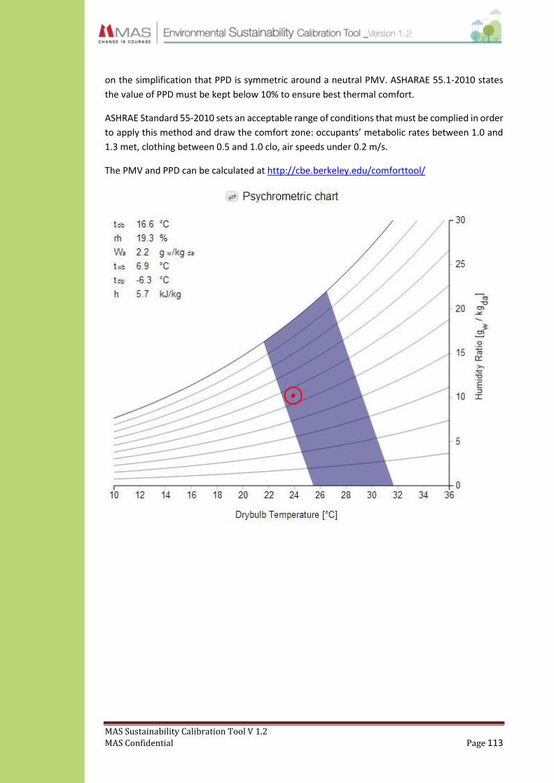
MAS Sustainability Calibration Tool V 1.2
MAS Confidential Page 113
on the simplification that PPD is symmetric around a neutral PMV. ASHARAE 55.1-2010 states
the value of PPD must be kept below 10% to ensure best thermal comfort.
ASHRAE Standard 55-2010 sets an acceptable range of conditions that must be complied in order
to apply this method and draw the comfort zone: occupants’ metabolic rates between 1.0 and
1.3 met, clothing between 0.5 and 1.0 clo, air speeds under 0.2 m/s.
The PMV and PPD can be calculated at http://cbe.berkeley.edu/comforttool/

MAS Sustainability Calibration Tool V 1.2
MAS Confidential Page 114
IEQ ANX G
Table : List of Low VOC paints in Sri Lanka
Asian Paints
Product Name Coating Type VOC in grams/Litre
Tractor Emulsion - Smooth Wall Finish (White) Flat 24.14
Royale Luxury Emulsion (Regal White) Non-Flat 55.62
Royale Shyne (White) Non-Flat 56.31
Apex Ultima Weather Proof Exterior Emulsion (Brilliant White) Non-Flat 33.67
Apex Weather Proof Exterior Emulsion (Classic White) Non-Flat 32.34
Ace Exterior Emulsion (White) Flat 22.22
Tractor Acrylic Distemper (Snow White) Flat 28.22
Premium Emulsion (White) Flat 41.3
Robbialac
Safecoat, Emulsion , Weathercoat, Ceiling White Flat Less than 50
Non Flat top Coat- Tuffkote Paint Non Flat Less than 50
Gloss -Robbialac Aqua Enamel , Non Flat Less Than 50
Robbialac Enamel, Non Flat Less than 400
Robbialac varnish Non Flat Less than 400
Semi-Gloss -Robbialac Aqua Enamel( Satin) Non Flat Less than 50
- Robbialac egg shell Non Flat Less than 400
Non Flat top Coat - Robbialac Patashop Enamel Non Flat Less than 400
Primer Or Undercoat – Lankem -Wallkote, Primer/undercoat Less than 50
Robbialac Wallfiller, Primer/undercoat Less than 50
Lankem Skimcoat Primer/undercoat zero
Robbialac Crack Bridging primer, Primer/undercoat Less than 50
Robbialac Aquablock Primer/undercoat Less than 400
Robbialac Alkali Resistance Primer Primer/undercoat Less than 400
Floor paint - W/B 2k Kemikote Flat Less than 50
- Kemikote Floor paint Flat Less than 500
Flat top coat - Robbialac Patashop Emulsion , Flat Less than 50
Robbialac patashop W/coat Flat less than 50
Anti-corrosive coating – Robbialac A/C paint, Anticorrosive Less than 400
Robbialac Alkyd Zinc Phosphate, Anticorrosive less than 400
Epoxy ZincPhosphate, Anticorrosive less than 250
Reflective roof coating - Robbialac FlexibleRoofing Reflective Less than 50
Dulux
Dulux Pentalite flat 41
Glidden Max Emulsion flat 50

MAS Sustainability Calibration Tool V 1.2
MAS Confidential Page 115
Dulux Light and Space non flat 67
Dulux 3 in 1 non flat 51
Recycle Paints flat 37
Dulux Weathershield flat 26
Dulux MP Weathershield non flat 69
Glidden Duraguard flat 45
Dulux Gloss non flat 415
Dulux MP Gloss non flat 399
Glidden Max Enamel non flat 417
WE ANX A
10.6.1 Drinking Water Standard (for pipe borne water: SLS614:1983)
PARAMETER Highest Desirable level Minimum permissible level
A Physio-Chemical
Electrical conductivity at 25°C µs/cm 750 3500
Total solids (mg/l) 500 2000
Colour (Hazen Units) 5 30
Taste Unobjectionable -
Odour Unobjectionable -
Turbidity (NTU) 2 8
Chloride CL (mg/l) 200 1200
FluorideF (mg/l) - 1.5
Iron Fe (mg/l) 0.3 1
Manganese (Mn) (mg/l) 0.05 0.5
Copper Cu (mg/l) 0.05 1.5
Zinc Zn (mg/l) 5 15
Calcium Ca (mg/l) 100 240
Magnesium Mg (mg/l) 30 150
Total Phosphates (PO4) (mg/l) - 2
Sulphate (S04) (mg/l) 200 400
Total Alkalinity (as CaCO3) (mg/l) 200 400
Total Hardness (as CaCO3) (mg/l) 250 600
Free Ammonia (as NH3) (mg/l) - 0.06
Nitrate (NO3) (mg/l) - 45
Nitrite (NO2 ) (mg/l) - 0.01
pH 7 0 - 8.5 6 5 - 9 0
Arsenic (As) (mg/l) - 0.05
Cadmium (Cd) (mg/l) - 0.005
Chromium (Cr) (mg/l) - 0.05

MAS Sustainability Calibration Tool V 1.2
MAS Confidential Page 116
Cyanide CN (mg/l) - 0.05
lead (Pb) (mg/l) - 0.05
Mercury Hg (mg/l) - 0.005
Selenium (Se) (mg/l) - 0.01
Free Residual Chlorine (as Chlorine) (mg/l) - 0.2
Polynuclier aromatic hydrocarbons (mg/l) - 0.0002
Phenolic compounds (as phenolic 0H) (mg/l) 0.001 0.002
Grease & Oil (mg/l) - 1
COD (Chemical Oxygen Demand) (mg/l) - 10
Radioactive materials
Gross alpha radioactivity (pC/l) - 3
Gross beta radioactivity (pC/l) - 30
Bacteriological
Total Coliforms /100 ml Absent in (i) 95% of the samples in year end, and any two consecutive
samples
10
E.Coli/100ml Absent Absent

MAS Sustainability Calibration Tool V 1.2
MAS Confidential Page 117
WE ANX B
10.6.2 Tolerance limits for the discharged of industrial waste water into inland surface waters as per BOI-Sri Lanka
No. Parameter Unit (Type of limit) Tolerance Limit Value
1 Total suspended solids mg/l, max 50
2 Particle size of the total suspended µm, Iess than 850
solids
3 pH at ambient temperature - 6.0-83
Biochemical Oxygen Demand mg/l, max 30
(BOD5, in five days at 20°C or
BOD3, in three day, at 27°C)
Temperature Discharge °C. max. Shall not exceed 40°C in any section of the
stream within, 15m downstream from the effluent outlet
Oils and grease, mg/l, max 10
7 Phenolic compounds (as phenolicOH) mg/l, max 1
8 Chemical Oxygen Demand (COD) mg/l, max 250
9 Colour
Wave length range Maximum spectral absorption coefficient
436nm (Yellow range) 7/m
525 (Red rance) 5/m
620 (Mac range) 3/m
10 Dissolved phosphates (as P) mg/l, max 5
11 Total Kjedahl nitrogen (as N) mg/l, max 150
12 Ammonical Nitrogen mg/l, max 50
13 Cyanide (as CN-) mg/l, max 0.2
14 Total residual chlorine mg/l, max 1
15 Fluorides (as f-) mg/l, max 2
16 Sulphides (as s2-) mg/l, max 2
17 Arsenic (as As) mg/l, max 0.2
18 Cadmium (as Cd) mg/l, max 0.1
19 Chromium, total (as Cr) mg/l, max 0.5
20 Chromium, Hexavalent (as C56+) mg/l, max 0.1
21 Copper (as Cu) mg/l, max 3
22 Iron (as Fe) mg/l, max 3
23 Lead (as Pb) mg/l, max 0.1
24 Mercury (as Hg) mg/l, max 0.0005
25 Nickel (as Ni) 3
26 Selenium (as Sc) 0.05
27 Zinc (as Zn) 2.0
28 Pesticides 0.005
29 Detergents/surfactants 5
30 Faecal Coliform 40
31 Radioactive material Between 10-8 and 10-7

MAS Sustainability Calibration Tool V 1.2
MAS Confidential Page 118
WE ANX C
10.6.3: Tolerance limits for the discharged of industrial waste water on land for irrigation purpose as per BOI-Sri Lanka
No: Parameter Unit (Type of limit) Tolerance Limit Value
1 Total dissolved solids mg/l, max 2100
2 pH at ambient temperature - 5.5-9.0
3 Biochemical Oxygen Demand mg/l, max 250
(BODs in five days at 20°C or BODs in three days at 27°C)
4 Oils and greases mg/l, max 10
5 Chemical Oxygen Demand (COD) mg/l, max 400
6 Chlorides (as Cl) mg/l, max 600
7 Sulphates (as S04) mg/l, max 1000
8 Boron (as B) mg/l, max 2
9 Arsenic (as As) mg/l, max 0.2
10 Cadmium (as Cd) mg/l, max 2
1 1 Chromium, total (as Cr) mg/l, max 1
12 Lead (as Pb) mg/l, max 1
13 Mercury (as Hg) mg/l, max 0.01
14 Sodium Adsorption Ration (SAR) - 10-15
15 Residual Sodium Carbonate (RSC) mol/l, max 2.5
16 Electrical conductivity µ/cm. max. 2250
17 Fecal Coliform MPN/100ml, max. 40
1 8 Copper (as Cu) mg/l, max 1
19 Cyanide (as CN) mg/l, max 0.2
20 Radio Active Material:
(c) Alpha MIMI'S micro curie/ml, max 10^-9
(d) Beta emitters micro curie/ml, max 10^-8
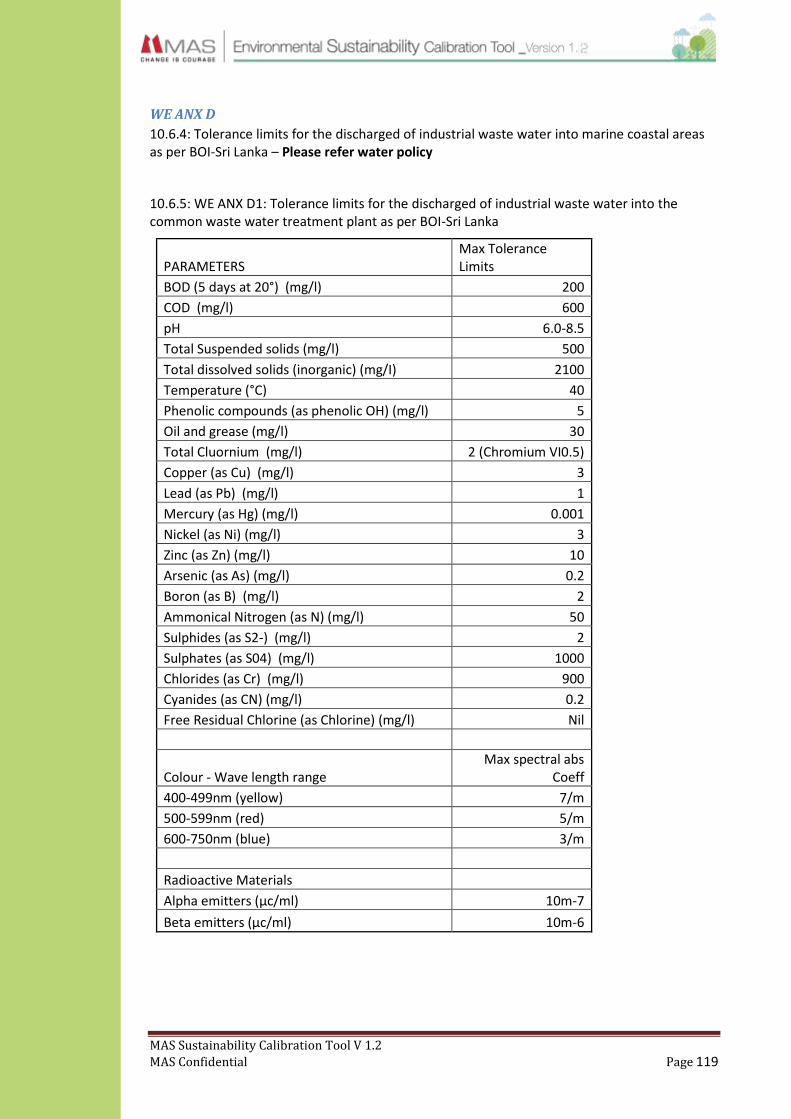
MAS Sustainability Calibration Tool V 1.2
MAS Confidential Page 119
WE ANX D
10.6.4: Tolerance limits for the discharged of industrial waste water into marine coastal areas as per BOI-Sri Lanka – Please refer water policy
10.6.5: WE ANX D1: Tolerance limits for the discharged of industrial waste water into the common waste water treatment plant as per BOI-Sri Lanka
PARAMETERS Max Tolerance Limits
BOD (5 days at 20°) (mg/l) 200
COD (mg/l) 600
pH 6.0-8.5
Total Suspended solids (mg/l) 500
Total dissolved solids (inorganic) (mg/I) 2100
Temperature (°C) 40
Phenolic compounds (as phenolic OH) (mg/l) 5
Oil and grease (mg/l) 30
Total Cluornium (mg/l) 2 (Chromium VI0.5)
Copper (as Cu) (mg/l) 3
Lead (as Pb) (mg/l) 1
Mercury (as Hg) (mg/l) 0.001
Nickel (as Ni) (mg/l) 3
Zinc (as Zn) (mg/l) 10
Arsenic (as As) (mg/l) 0.2
Boron (as B) (mg/l) 2
Ammonical Nitrogen (as N) (mg/l) 50
Sulphides (as S2-) (mg/l) 2
Sulphates (as S04) (mg/l) 1000
Chlorides (as Cr) (mg/l) 900
Cyanides (as CN) (mg/l) 0.2
Free Residual Chlorine (as Chlorine) (mg/l) Nil
Colour - Wave length range Max spectral abs
Coeff
400-499nm (yellow) 7/m
500-599nm (red) 5/m
600-750nm (blue) 3/m
Radioactive Materials
Alpha emitters (µc/ml) 10m-7
Beta emitters (µc/ml) 10m-6

MAS Sustainability Calibration Tool V 1.2
MAS Confidential Page 120
Note: WE ANX D2
The quality of waste water discharged into common sewers or collection system should be such
to ensure that the waste water;
1. Does not damage the sewer by physical or chemical action;
2. Does not endanger the health of the workers cleaning the sewer;
3. Does not upset the processes that are normally used in sewage treatment;
4. Does not overload the common treatment plant;
5. Does not damage the crops or affect the soil an case the effluent after treatment is
used for irrigation and,
6. Does not create fire and explosion hazards due to certain constituent present in the
effluent
The industrial effluents not conforming to the specified tolerance limits or containing solids
such as ash, sands, feathers, large floatable items, straw, plastics, wood, lime slurry, residue,
beer or distillery slops, chemical or paint residue, gross solids from cannery wastes, cinder,
sand. tar, hair, rags, metal shavings, garbage and broken glass shall not be permitted to be
discharged directly into the common sewer line leading to the waste water treatment plant.
Such effluents have to be subjected to an in house treatment to bring them to be within the
suggested tolerance limits and or to free them from the undesirable material mentioned above
prior to discharge into the sewer line.
WE ANX E
10.6.6 LEED V3 – EB for O&M
Table : UPC / IPC standards for plumbing fixture water use
Fixture UPC/IPC Stnd EPA water sense Stnd
Water closets (gpf) 1.60 1.28
Urinals (gpf) 1.00 0.50
Shower heads (gpm) 2.50 1.5-2.0
Faucets and aerators (gpm)
Public lavatory 0.5
Private lavatory 2.2 1.5
Kitchen & janitorial sink faucets 2.20
Metering faucets (gpc) 0.25
Public metering lavatory faucets 0.25
1 Gallon = 3.85 Liters. Gallons per flush= gpf. Gallons per minute=gpm. Gallons per cycle=gpc IPC=International plumbing code. UPC=Uniform plumbing code
Reference : LEED V3 EBOM
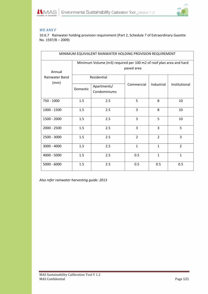
MAS Sustainability Calibration Tool V 1.2
MAS Confidential Page 121
WE ANX F
10.6.7 Rainwater holding provision requirement (Part 2, Schedule 7 of Extraordinary Gazette No. 1597/8 – 2009)
MINIMUM EQUIVALENT RAINWATER HOLDING PROVISION REQUIREMENT
Annual
Rainwater Band
(mm)
Minimum Volume (m3) required per 100 m2 of roof plan area and hard
paved area
Residential
Commercial Industrial Institutional Domestic
Apartments/
Condominiums
750 - 1000 1.5 2.5 5 8 10
1000 - 1500 1.5 2.5 3 8 10
1500 - 2000 1.5 2.5 3 5 10
2000 - 2500 1.5 2.5 3 3 5
2500 - 3000 1.5 2.5 2 2 3
3000 - 4000 1.5 2.5 1 1 2
4000 - 5000 1.5 2.5 0.5 1 1
5000 - 6000 1.5 2.5 0.5 0.5 0.5
Also refer rainwater harvesting guide: 2013

MAS Sustainability Calibration Tool V 1.2
MAS Confidential Page 122
10.6.8 Unit Conversions and Some Definitions
Measurement SI Unit Other Related Conversions
1 Volume 1 m3 = ( 1mx1mx1m)
1000 Ltrs ( 1 Ltr = 1000 ml)
35.314 ft3
264.172 US Gallon
2 Weight 1 kg 1000 g (1g=1000mg)
2.205 Pound (lb)
3 Area 1 m2 = (1mx1m)
10.764 sq.ft
0.000247 Acres (1 Acres = 4046.856 m2)
4 Pressure 1 Pa= 1 kg/(m s2)
10-5 bar (1 bar = 105 Pa)
1 N/m2
(1 bar = 0.987 atm)
(1m H2O = 0.0968 atm)
5 Density 1 kg/m3 0.0624 lb/ft3
1 g /ltr
1000 g/m3
6 Flow Rate 1 m3 / s 264.172 gal / s
4.403 gpm
1000 Ltrs / s
7 Length m 1m = 0.001 km
1m = 39.37 inches
1 in. = 25.4 mm = 2.54 cm
8 Temperature 0 C 0 C = (0F - 32) / 1.8
9 Viscosity 1 m2/ s1 1550.003 in2/S
10.753 ft2/ S
Definitions
1 Absolute Pressure Pressure above absolute Vacuum - 0 atm. Used for Cavitation Calculations.
2 Gauge Pressure Over Pressure higher than the normal Atmos. Press. of 1atm. Normal Pressure Gauges show this.
3 Head How High the Pump can lift a Liquid ,(m) and independent of Liq. Density
4 Pump's Energy Power Transferred to the Liquid,(PH) = Power Input to the Pump (Shaft Power) P2 x Pump Efficiency.
P1 = Power Input to the Motor from the Distribution(Consumer pays for) Single Phase : P1 = V x I x CosΦ. Three Phase : P1 = √3 x V x I x CosΦ
Use Bernoulli’s Equation and Friction Factor Calculations for Pipe flow.

MAS Sustainability Calibration Tool V 1.2
MAS Confidential Page 123
WM ANX A : Recommended Disposal Methods for All Waste Types
Type of waste Mandatory method of disposal
Recommended method of disposal
Garments – Logo(Garments with Customer' Logo, Unique Prints or designs)
Should be shredded and sold to a recognized waste fabric collector for reuse / recycle. Items that are not recyclable should be sent to Geocycle
Garments – Non logo (Garments which do not carry Customer Logo, Unique Prints or Designs)
Stocks must be transferred to BPU
Rejected Panels (Logo / non-logo)
Should be shredded and sold to a recognized waste fabric collector for reuse / recycle
Fabric /Lace – Logo Should be shredded and sold to a recognized waste fabric collector for reuse / recycle
Fabric / Lace – Solid Stocks must be transferred to BPU
Fabric waste contaminated by chemicals / dye
Send to Geocycle
Foam waste (not molded) Sell to third party for reuse / recycling
Foam waste (molded) Sell to third party for recycling Send to Geocycle
Trims – Logo (including customer labels)
Should be shredded and sold to a recognized waste fabric collector for reuse / recycle
Trims- with no customer identification
Sell to third party for reuse / recycle
Art work used in printing Should be shredded and sold to a third party for reuse / recycle. Items that are not recyclable should be sent to Geocycle
Used Thread cones Send back to supplier for reuse
Plastic and polythene waste contaminated by food / drink
Send to Geocycle
Polythene and plastic Sell to a third party for recycle
Corrugated boxes Send back to supplier (local) for reuse. If supplier is overseas sell for recycling
Paper contaminated by food Send to Geocyle
Cardboard and paper Sell to third party for recycling

MAS Sustainability Calibration Tool V 1.2
MAS Confidential Page 124
Food waste Sell as animal feed or compost on site
Cooking waste Sell as animal feed or compost on site
Coconut shells Sell to third party for recycling (manufacture of charcoal)
Gardening waste Compost on site or sell for composting at outside location
Waste needles Sell to a third party for recycling
Other metal waste Sell or handover to third party for recycle or reuse
Glass Sell to a third party for recycling
Toner and Inkjet Cartridges Send for reuse to supplier
E-waste Handover to licensed e-waste collector for safe disposal
Fluorescent bulbs Handover to Asia Recycling for safe disposal
Sludge – Chemical Send to Geocycle for appropriate disposal
Sludge – Biological Use as fertilizer within the factory premises. Not recommended to be used for food crops / home gardening
Chemical Containers / Empty paint buckets
Send to Geocycle. If the plant has an ETP with chemical treatment, the containers could be washed and sold for recycling.
Used Machine Oil Sell to service stations for reuse. Recommended to use as fuel for in-house boilers after proper analysis.
Used Lead Acid Batteries Dispose as per e-waste section
No waste type should be burnt / incinerated within the premises or sold to an outside party for burning / incineration, excluding those wastes sold to a CEA approved incineration facility.
EM ANX A: Emission factors for different types of fuel
Fuel type Emission factor -CO2e kg/unit
Diesel (l) 2.79
Kerosene(l) 2.6
HFO (l) 3.117
LPG (kg) 2.75

MAS Sustainability Calibration Tool V 1.2
MAS Confidential Page 125
Purchased electricity Emission factor –CO2e kg /kWh
2010 0.692
2011/2012/2013 (subject to revision) 0.7047
EM ANX B: Refrigerants and GWP
Industrial
Designation or Common Name
Chemical
Formula
Lifetime
(years)
RadiativeEfficiency
(W m–2 ppb–1) GWP
Hydrofluorocarbons
HFC-23 CHF3 270 0.19 11,700
HFC-32 CH2F2 4.9 0.11 650
HFC-125 CHF2CF3 29 0.23 2,800
HFC-134a CH2FCF3 14 0.16 1,300
HFC-143a CH3CF3 52 0.13 3,800
HFC-152a CH3CHF2 1.4 0.09 140
HFC-227ea CF3CHFCF3 34.2 0.26 2,900
HFC-236fa CF3CH2CF3 240 0.28 6,300
HFC-245fa CHF2CH2CF3 7.6 0.28
HFC-365mfc CH3CF2CH2CF3 8.6 0.21
HFC-43-10mee CF3CHFCHFCF2CF3 15.9 0.4 1,300
Perfluorinated compounds
Sulphur hexafluoride
SF6 3,200 0.52 23,900
Nitrogen trifluoride NF3 740 0.21
PFC-14 CF4 50,000 0.1 6,500
PFC-116 C2F6 10,000 0.26 9,200
Perfluorinated compounds
PFC-218 2,600 0.26 7,000
PFC-318 3,200 0.32 8,700
PFC-3-1-10 2,600 0.33 7,000
PFC-4-1-12 4,100 0.41
PFC-5-1-14 3,200 0.49 7,400
PFC-9-1-18 >1,000d 0.56
trifluoromethyl
sulphur pentafluoride
800 0.57
Fluorinated ethers
HFE-125 136 0.44
HFE-134 26 0.45
HFE-143a 4.3 0.27

MAS Sustainability Calibration Tool V 1.2
MAS Confidential Page 126
HCFE-235da2 2.6 0.38
HFE-245cb2 5.1 0.32
HFE-245fa2 4.9 0.31
HFE-254cb2 2.6 0.28
HFE-347mcc3 5.2 0.34
HFE-347pcf2 7.1 0.25
HFE-356pcc3 0.33 0.93
HFE-449sl (HFE-
7100) 3.8 0.31
HFE-569sf2 (HFE-
7200) 0.77 0.3
HFE-43-10pccc124
(H-Galden 1040x) 6.3 1.37
HFE-236ca12 (HG-10)
12.1 0.66
HFE-338pcc13 (HG-
01) 6.2 0.87
Perfluoropolyethers
PFPMIE 800 0.65
Hydrocarbons and other compounds – Direct Effects
Dimethylether 0.015 0.02
Methylene chloride 0.38 0.03
Methyl chloride 1 0.01
EM ANX C: Substances controlled by Montreal Protocol
Industrial Designation or
Common Name
(years)
Chemical
Formula
Lifetime
(years)
RadiativeEfficiency
(W m–2 ppb–1) GWP
Carbon dioxide CO2 b1.4x10–5 1
Methanec CH4 12c 3.7x10⁻⁴ 21
Nitrous oxide N2O 114 3.03x10⁻³ 310
Substances controlled by the Montreal Protocol
CFC-11 CCl3F 45 0.25 3,800
CFC-12 CCl2F2 100 0.32 8,100
CFC-13 CClF3 640 0.25
CFC-113 CCl2FCClF2 85 0.3 4,800
CFC-114 CClF2CClF2 300 0.31
CFC-115 CClF2CF3 1,700 0.18
Halon-1301 CBrF3 65 0.32 5,400
Halon-1211 CBrClF2 16 0.3

MAS Sustainability Calibration Tool V 1.2
MAS Confidential Page 127
Halon-2402 CBrF2CBrF2 20 0.33
Carbon
tetrachloride CCl4 26 0.13 1,400
Methyl bromide CH3Br 0.7 0.01
Methyl chloroform CH3CCl3 5 0.06
HCFC-22 CHClF2 12 0.2 1,500
HCFC-123 CHCl2CF3 1.3 0.14 90
HCFC-124 CHClFCF3 5.8 0.22 470
HCFC-141b CH3CCl2F 9.3 0.14
HCFC-142b CH3CClF2 17.9 0.2 1,800
HCFC-225ca CHCl2CF2CF3 1.9 0.2
HCFC-225cb CHClFCF2CClF2 5.8 0.32
EM ANX D: Recommended practice for stack emissions & height based on the
regulations under National Environmental Act
Standard limits for Pollutants:
Fuel Type
Particulate
Matter (PM)
(mg/Nm3)
Sulphur
Dioxide (SOx)
(mg/Nm3)
Nitrogen
Oxides (NOx)
(mg/Nm3)
Excess O2
Content
%
Liquid/Gas 150 1000 500 3
Standards on Stack Height:
Minimum chimney height C (m) in meters of any combustion point source is defined by
the following equation.
C (m) = H (m) + 0.6 U (m)
C : Minimum chimney height
H : Height of tallest building within 5U radius of the chimney
U : Uncorrected height for heat input
U = 1.36Q0.6
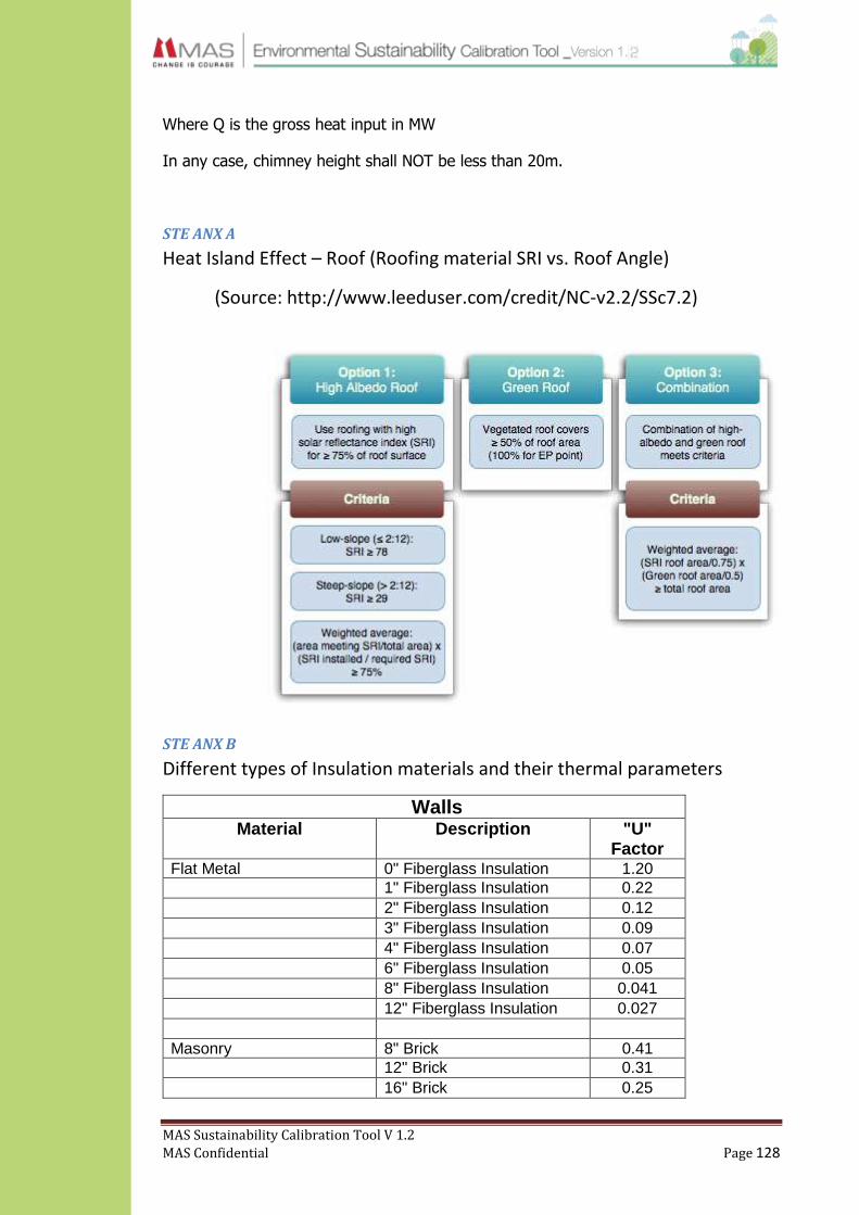
MAS Sustainability Calibration Tool V 1.2
MAS Confidential Page 128
Where Q is the gross heat input in MW
In any case, chimney height shall NOT be less than 20m.
STE ANX A
Heat Island Effect – Roof (Roofing material SRI vs. Roof Angle)
(Source: http://www.leeduser.com/credit/NC-v2.2/SSc7.2)
STE ANX B
Different types of Insulation materials and their thermal parameters
Walls
Material Description "U" Factor
Flat Metal 0" Fiberglass Insulation 1.20 1" Fiberglass Insulation 0.22 2" Fiberglass Insulation 0.12 3" Fiberglass Insulation 0.09 4" Fiberglass Insulation 0.07 6" Fiberglass Insulation 0.05 8" Fiberglass Insulation 0.041 12" Fiberglass Insulation 0.027 Masonry 8" Brick 0.41 12" Brick 0.31 16" Brick 0.25

MAS Sustainability Calibration Tool V 1.2
MAS Confidential Page 129
8" Conic Block, Solid 0.39 12" Conic Block, Solid 0.36 4" Conic Block, Hollow 0.51 8" Conic Block, Hollow 0.39 12" Conic Block, Hollow 0.37 Poured Concrete 2" Thick 0.99 (140 lb. / ft3) 4" Thick 0.86 6" Thick 0.75 8" Thick 0.67 10" Thick 0.61 12" Thick 0..55 Poured Concrete 2" Thick 0.62 (80 lb. / ft.3) 4" Thick 0.42 6" Thick 0.31 8" Thick 0.25 10" Thick 0.21 12" Thick 0.18
Doors
Material Description "U" Factor
Steel No Fiberglas Insulation 1.20 Insulated 0.65 Wood 1" Thick 0.64
Roofs
Material Description "U" Factor
Flat Metal - Roof 0" Fiberglass Insulation 0.90 1" Fiberglass Insulation 0.26 2" Fiberglass Insulation 0.16 3" Fiberglass Insulation 0.11 4" Fiberglass Insulation 0.071 6" Fiberglass Insulation 0.05 8" Fiberglass Insulation 0.039 12" Fiberglass Insulation 0.027 Wood - Roof 0" Fiberglass Insulation 0.48 1" Fiberglass Insulation 0.21 2" Fiberglass Insulation 0.12 3" Fiberglass Insulation 0.10 4" Fiberglass Insulation 0.075

MAS Sustainability Calibration Tool V 1.2
MAS Confidential Page 130
6" Fiberglass Insulation 0.052 8" Fiberglass Insulation 0.04 12" Fiberglass Insulation 0.027 Concrete Deck - Roof 2" Thick 0.30 3" Thick 0.23 4" Thick 0.18 Sky Lights Single Wall 1.15 Double Wall 0.70
Floors - Exterior Exposure
Material Description "U" Factor
Floor - Exterior exposure Insulated 0.55 Un-Insulated 0.81
Windows
Material Description "U" Factor
Glass Single Pane 1.22 Double Pane 0.70 Fiberglass Panels 1.09

MAS Sustainability Calibration Tool V 1.2
MAS Confidential Page 131
CM ANX A: Material Safety Data Sheet (MSDS)
Preferred MSDS

MAS Sustainability Calibration Tool V 1.2
MAS Confidential Page 132
Non-Preferred MSDS

MAS Sustainability Calibration Tool V 1.2
MAS Confidential Page 133
CM ANX B: Additional Information of Dyes/Chemicals
Technical Data Sheet (TDS)

MAS Sustainability Calibration Tool V 1.2
MAS Confidential Page 134
Certificate of Analysis (CoA)

MAS Sustainability Calibration Tool V 1.2
MAS Confidential Page 135
CM ANX C: Positive List
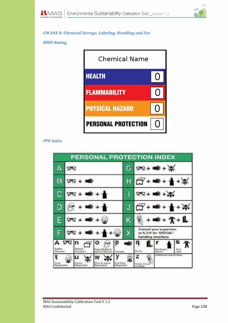
MAS Sustainability Calibration Tool V 1.2
MAS Confidential Page 136
CM ANX D: Chemical Storage, Labeling, Handling and Use
HMIS Rating
PPE Index