enocean wireless systems – range planning guide
TRANSCRIPT
WHITE PAPER
EnOcean GmbH Kolpingring 18a 82041 Oberhaching Germany
Tel. +49.89.67 34 689-0 Fax +49.89.67 34 689-50 [email protected] www.enocean.de
Dipl. Ing. Armin Anders Subject to modifications October 2008 Page 1/ 12
Wireless systems provide much simpler installation as well as the flexibility to relocate or add to a system, compared to installing wired systems. The easy recommendations in this planning guide are provided to ensure successful installation and reliable operation of robust EnOcean building radio net-works.
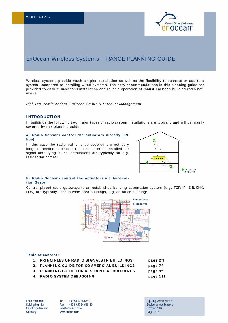
Dipl. Ing. Armin Anders, EnOcean GmbH, VP Product Management INTRODUCTION In buildings the following two major types of radio system installations are typically and will be mainly covered by this planning guide: a) Radio Sensors control the actuators directly (RF bus)
In this case the radio paths to be covered are not very long. If needed a central radio repeater is installed for signal amplifying. Such installations are typically for e.g. residential homes:
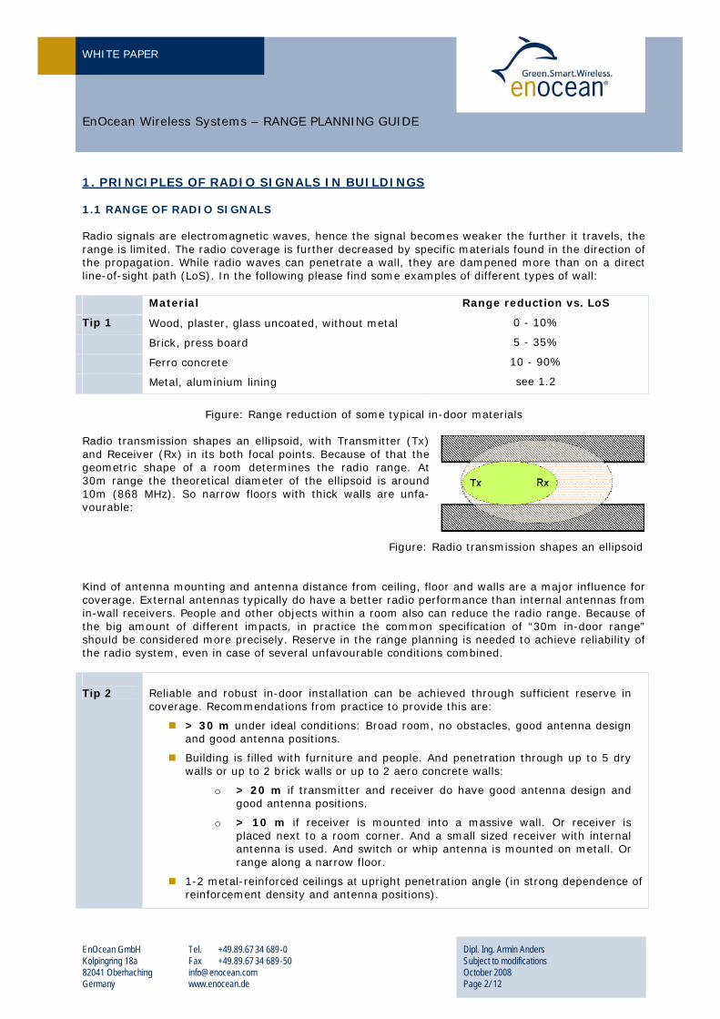
b) Radio Sensors control the actuators via Automa-tion System
Central placed radio gateways to an established building automation system (e.g. TCP/IP, EIB/KNX, LON) are typically used in wide-area buildings, e.g. an office building:
Table of content:
1. PRINCIPLES OF RADIO SIGNALS IN BUILDINGS page 2ff
2. PLANNING GUIDE FOR COMMERCIAL BUILDINGS page 7f
3. PLANNING GUIDE FOR RESIDENTIAL BUILDINGS page 9f
4. RADIO SYSTEM DEBUGGING page 11f
EnOcean Wireless Systems – RANGE PLANNING GUIDE
Transmitter
or Receiver
WHITE PAPER
EnOcean GmbH Kolpingring 18a 82041 Oberhaching Germany
Tel. +49.89.67 34 689-0 Fax +49.89.67 34 689-50 [email protected] www.enocean.de
Dipl. Ing. Armin Anders Subject to modifications October 2008 Page 2/ 12
EnOcean Wireless Systems – RANGE PLANNING GUIDE
U1. PRINCIPLES OF RADIO SIGNALS IN BUILDINGS 1.1 RANGE OF RADIO SIGNALS Radio signals are electromagnetic waves, hence the signal becomes weaker the further it travels, the range is limited. The radio coverage is further decreased by specific materials found in the direction of the propagation. While radio waves can penetrate a wall, they are dampened more than on a direct line-of-sight path (LoS). In the following please find some examples of different types of wall: Material Range reduction vs. LoS
Tip 1 Wood, plaster, glass uncoated, without metal 0 - 10%
Brick, press board 5 - 35%
Ferro concrete 10 - 90%
Metal, aluminium lining see 1.2
Figure: Range reduction of some typical in-door materials
Radio transmission shapes an ellipsoid, with Transmitter (Tx) and Receiver (Rx) in its both focal points. Because of that the geometric shape of a room determines the radio range. At 30m range the theoretical diameter of the ellipsoid is around 10m (868 MHz). So narrow floors with thick walls are unfa-vourable:
Figure: Radio transmission shapes an ellipsoid Kind of antenna mounting and antenna distance from ceiling, floor and walls are a major influence for coverage. External antennas typically do have a better radio performance than internal antennas from in-wall receivers. People and other objects within a room also can reduce the radio range. Because of the big amount of different impacts, in practice the common specification of “30m in-door range” should be considered more precisely. Reserve in the range planning is needed to achieve reliability of the radio system, even in case of several unfavourable conditions combined. Tip 2
Reliable and robust in-door installation can be achieved through sufficient reserve in coverage. Recommendations from practice to provide this are:
> 30 m under ideal conditions: Broad room, no obstacles, good antenna design and good antenna positions.
Building is filled with furniture and people. And penetration through up to 5 dry walls or up to 2 brick walls or up to 2 aero concrete walls:
o > 20 m if transmitter and receiver do have good antenna design and good antenna positions.
o > 10 m if receiver is mounted into a massive wall. Or receiver is placed next to a room corner. And a small sized receiver with internal antenna is used. And switch or whip antenna is mounted on metall. Or range along a narrow floor.
1-2 metal-reinforced ceilings at upright penetration angle (in strong dependence of reinforcement density and antenna positions).
WHITE PAPER
EnOcean GmbH Kolpingring 18a 82041 Oberhaching Germany
Tel. +49.89.67 34 689-0 Fax +49.89.67 34 689-50 [email protected] www.enocean.de
Dipl. Ing. Armin Anders Subject to modifications October 2008 Page 3/ 12
EnOcean Wireless Systems – RANGE PLANNING GUIDE
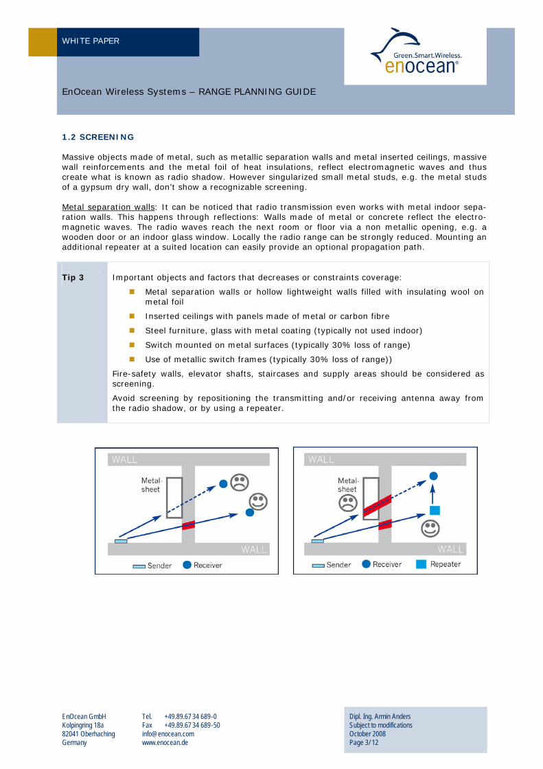
1.2 SCREENING Massive objects made of metal, such as metallic separation walls and metal inserted ceilings, massive wall reinforcements and the metal foil of heat insulations, reflect electromagnetic waves and thus create what is known as radio shadow. However singularized small metal studs, e.g. the metal studs of a gypsum dry wall, don’t show a recognizable screening. UMetal separation wallsU: It can be noticed that radio transmission even works with metal indoor sepa-ration walls. This happens through reflections: Walls made of metal or concrete reflect the electro-magnetic waves. The radio waves reach the next room or floor via a non metallic opening, e.g. a wooden door or an indoor glass window. Locally the radio range can be strongly reduced. Mounting an additional repeater at a suited location can easily provide an optional propagation path. Tip 3
Important objects and factors that decreases or constraints coverage:
Metal separation walls or hollow lightweight walls filled with insulating wool on metal foil
Inserted ceilings with panels made of metal or carbon fibre
Steel furniture, glass with metal coating (typically not used indoor)
Switch mounted on metal surfaces (typically 30% loss of range)
Use of metallic switch frames (typically 30% loss of range))
Fire-safety walls, elevator shafts, staircases and supply areas should be considered as screening.
Avoid screening by repositioning the transmitting and/or receiving antenna away from the radio shadow, or by using a repeater.
WHITE PAPER
EnOcean GmbH Kolpingring 18a 82041 Oberhaching Germany
Tel. +49.89.67 34 689-0 Fax +49.89.67 34 689-50 [email protected] www.enocean.de
Dipl. Ing. Armin Anders Subject to modifications October 2008 Page 4/ 12
EnOcean Wireless Systems – RANGE PLANNING GUIDE
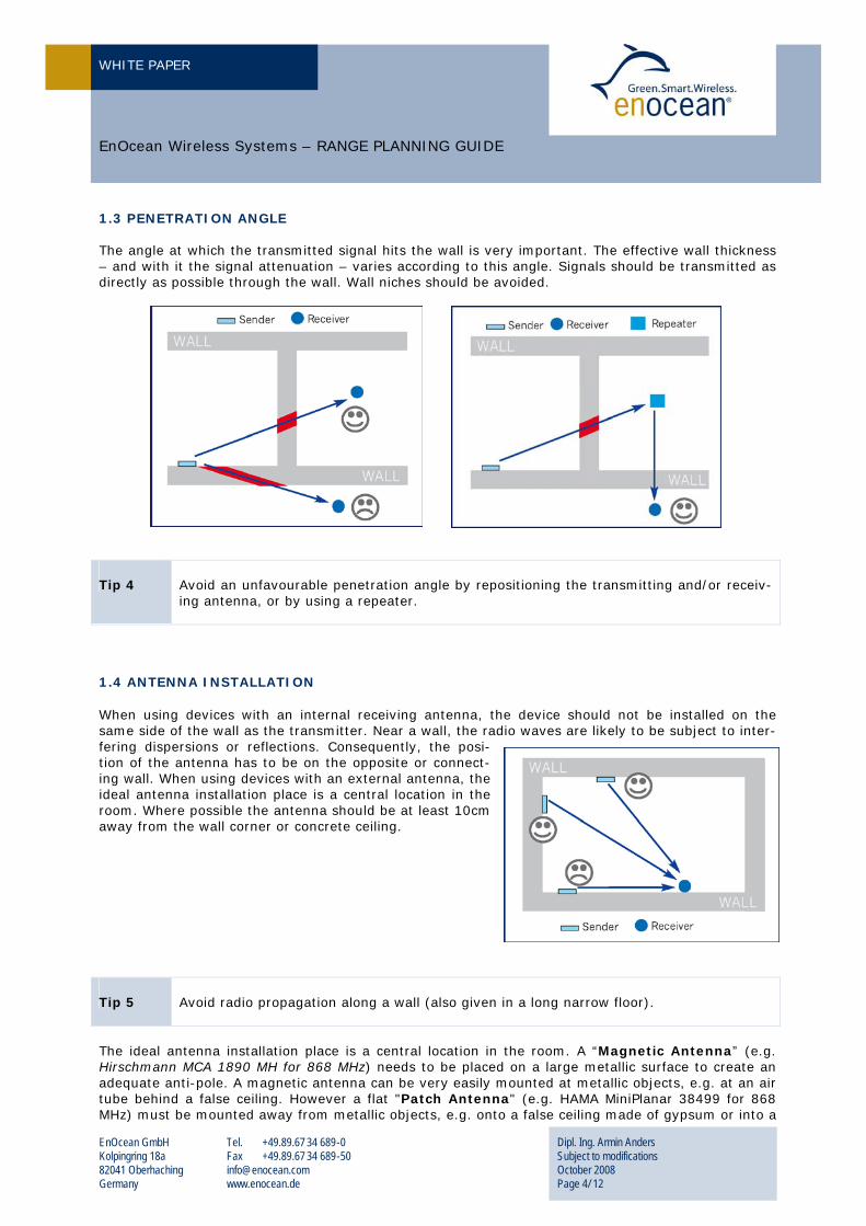
1.3 PENETRATION ANGLE The angle at which the transmitted signal hits the wall is very important. The effective wall thickness – and with it the signal attenuation – varies according to this angle. Signals should be transmitted as directly as possible through the wall. Wall niches should be avoided.
Tip 4
Avoid an unfavourable penetration angle by repositioning the transmitting and/or receiv-ing antenna, or by using a repeater.
1.4 ANTENNA INSTALLATION When using devices with an internal receiving antenna, the device should not be installed on the same side of the wall as the transmitter. Near a wall, the radio waves are likely to be subject to inter-fering dispersions or reflections. Consequently, the posi-tion of the antenna has to be on the opposite or connect-ing wall. When using devices with an external antenna, the ideal antenna installation place is a central location in the room. Where possible the antenna should be at least 10cm away from the wall corner or concrete ceiling.
Tip 5
Avoid radio propagation along a wall (also given in a long narrow floor).
The ideal antenna installation place is a central location in the room. A “Magnetic Antenna” (e.g. Hirschmann MCA 1890 MH for 868 MHz) needs to be placed on a large metallic surface to create an adequate anti-pole. A magnetic antenna can be very easily mounted at metallic objects, e.g. at an air tube behind a false ceiling. However a flat "Patch Antenna" (e.g. HAMA MiniPlanar 38499 for 868 MHz) must be mounted away from metallic objects, e.g. onto a false ceiling made of gypsum or into a
WHITE PAPER
EnOcean GmbH Kolpingring 18a 82041 Oberhaching Germany
Tel. +49.89.67 34 689-0 Fax +49.89.67 34 689-50 [email protected] www.enocean.de
Dipl. Ing. Armin Anders Subject to modifications October 2008 Page 5/ 12
EnOcean Wireless Systems – RANGE PLANNING GUIDE
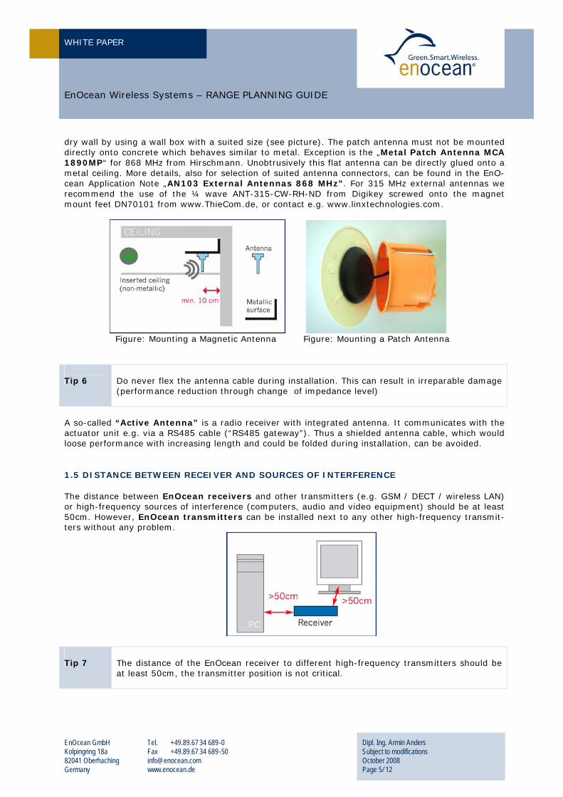
dry wall by using a wall box with a suited size (see picture). The patch antenna must not be mounted directly onto concrete which behaves similar to metal. Exception is the „Metal Patch Antenna MCA 1890MP“ for 868 MHz from Hirschmann. Unobtrusively this flat antenna can be directly glued onto a metal ceiling. More details, also for selection of suited antenna connectors, can be found in the EnO-cean Application Note „AN103 External Antennas 868 MHz”. For 315 MHz external antennas we recommend the use of the ¼ wave ANT-315-CW-RH-ND from Digikey screwed onto the magnet mount feet DN70101 from www.ThieCom.de, or contact e.g. www.linxtechnologies.com.
Figure: Mounting a Magnetic Antenna Figure: Mounting a Patch Antenna Tip 6
Do never flex the antenna cable during installation. This can result in irreparable damage (performance reduction through change of impedance level)
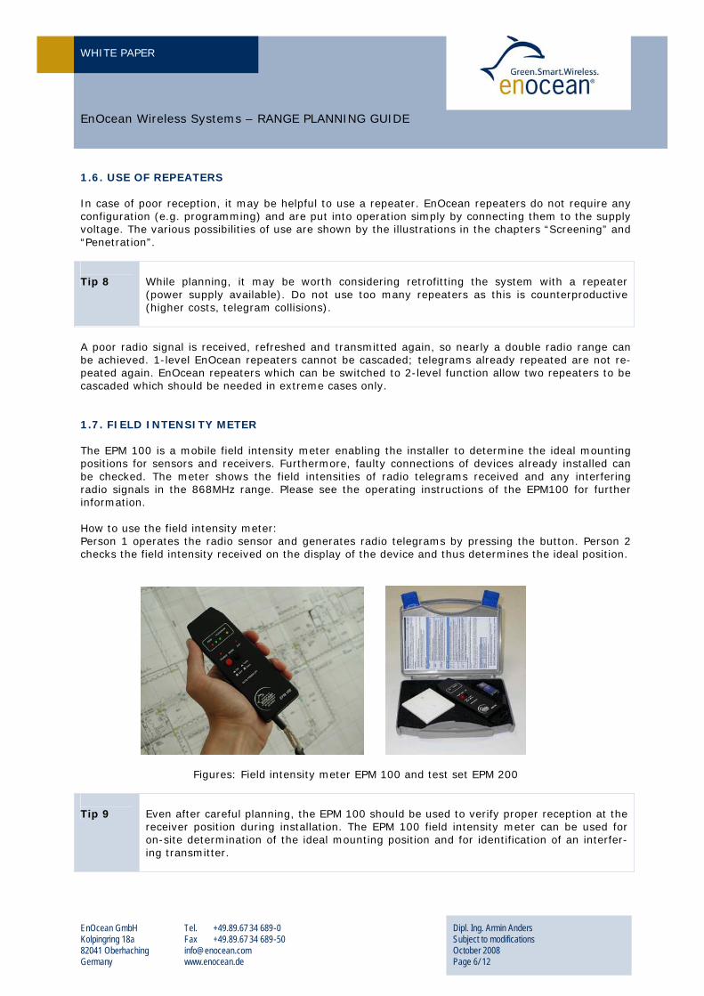
A so-called “Active Antenna” is a radio receiver with integrated antenna. It communicates with the actuator unit e.g. via a RS485 cable (“RS485 gateway”). Thus a shielded antenna cable, which would loose performance with increasing length and could be folded during installation, can be avoided. 1.5 DISTANCE BETWEEN RECEIVER AND SOURCES OF INTERFERENCE The distance between EnOcean receivers and other transmitters (e.g. GSM / DECT / wireless LAN) or high-frequency sources of interference (computers, audio and video equipment) should be at least 50cm. However, EnOcean transmitters can be installed next to any other high-frequency transmit-ters without any problem.
Tip 7
The distance of the EnOcean receiver to different high-frequency transmitters should be at least 50cm, the transmitter position is not critical.
WHITE PAPER
EnOcean GmbH Kolpingring 18a 82041 Oberhaching Germany
Tel. +49.89.67 34 689-0 Fax +49.89.67 34 689-50 [email protected] www.enocean.de
Dipl. Ing. Armin Anders Subject to modifications October 2008 Page 6/ 12
EnOcean Wireless Systems – RANGE PLANNING GUIDE
1.6. USE OF REPEATERS In case of poor reception, it may be helpful to use a repeater. EnOcean repeaters do not require any configuration (e.g. programming) and are put into operation simply by connecting them to the supply voltage. The various possibilities of use are shown by the illustrations in the chapters “Screening” and “Penetration”. Tip 8
While planning, it may be worth considering retrofitting the system with a repeater (power supply available). Do not use too many repeaters as this is counterproductive (higher costs, telegram collisions).
A poor radio signal is received, refreshed and transmitted again, so nearly a double radio range can be achieved. 1-level EnOcean repeaters cannot be cascaded; telegrams already repeated are not re-peated again. EnOcean repeaters which can be switched to 2-level function allow two repeaters to be cascaded which should be needed in extreme cases only. 1.7. FIELD INTENSITY METER The EPM 100 is a mobile field intensity meter enabling the installer to determine the ideal mounting positions for sensors and receivers. Furthermore, faulty connections of devices already installed can be checked. The meter shows the field intensities of radio telegrams received and any interfering radio signals in the 868MHz range. Please see the operating instructions of the EPM100 for further information. How to use the field intensity meter: Person 1 operates the radio sensor and generates radio telegrams by pressing the button. Person 2 checks the field intensity received on the display of the device and thus determines the ideal position.
Figures: Field intensity meter EPM 100 and test set EPM 200 Tip 9
Even after careful planning, the EPM 100 should be used to verify proper reception at the receiver position during installation. The EPM 100 field intensity meter can be used for on-site determination of the ideal mounting position and for identification of an interfer-ing transmitter.
WHITE PAPER
EnOcean GmbH Kolpingring 18a 82041 Oberhaching Germany
Tel. +49.89.67 34 689-0 Fax +49.89.67 34 689-50 [email protected] www.enocean.de
Dipl. Ing. Armin Anders Subject to modifications October 2008 Page 7/ 12
EnOcean Wireless Systems – RANGE PLANNING GUIDE
U2. PLANNING GUIDE FOR COMMERCIAL BUILDINGS The radio coverage in commercial buildings is usually restricted by fire safety walls that must be con-sidered as screening. Inside the fire protected sections lightweight or glass partition walls are used with good radio wave propagation properties (except for metal reinforcements or metalized walls!). The following are two common installation architectures
Radio Sensors control the Actuators directly (RF bus) Usually, the radio paths to be covered are not very long (“cubicle installation”).
Radio Sensors control the Actuators via Automation System
Central placed radio Gateways to the Building Automation System (e.g. TCP/IP, LON, EIB) are used for system coverage. In the following a reliable radio planning is shown that can be done in quick time and using simple tools only:
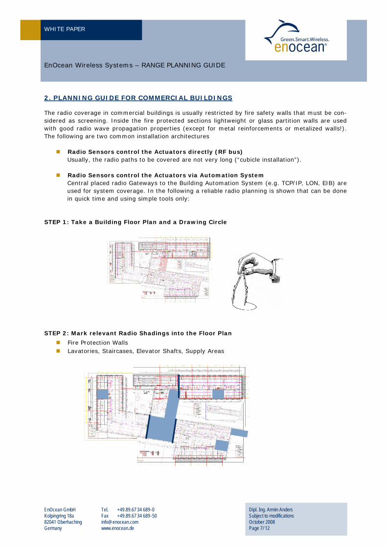
STEP 1: Take a Building Floor Plan and a Drawing Circle
STEP 2: Mark relevant Radio Shadings into the Floor Plan
Fire Protection Walls Lavatories, Staircases, Elevator Shafts, Supply Areas
WHITE PAPER
EnOcean GmbH Kolpingring 18a 82041 Oberhaching Germany
Tel. +49.89.67 34 689-0 Fax +49.89.67 34 689-50 [email protected] www.enocean.de
Dipl. Ing. Armin Anders Subject to modifications October 2008 Page 8/ 12
EnOcean Wireless Systems – RANGE PLANNING GUIDE
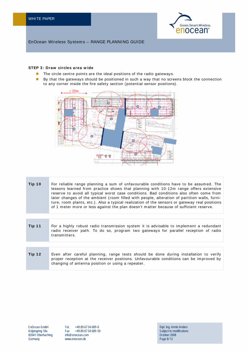
STEP 3: Draw circles area wide
The circle centre points are the ideal positions of the radio gateways. By that the gateways should be positioned in such a way that no screens block the connection
to any corner inside the fire safety section (potential sensor positions). Tip 10
For reliable range planning a sum of unfavourable conditions have to be assumed. The lessons learned from practice shows that planning with 10-12m range offers extensive reserve to avoid all typical worst case conditions. Bad conditions also often come from later changes of the ambient (room filled with people, alteration of partition walls, furni-ture, room plants, etc.). Also a typical realization of the sensors or gateway real positions of 1 meter more or less against the plan doesn’t matter because of sufficient reserve.
Tip 11
For a highly robust radio transmission system it is advisable to implement a redundant radio receiver path. To do so, program two gateways for parallel reception of radio transmitters.
Tip 12
Even after careful planning, range tests should be done during installation to verify proper reception at the receiver positions. Unfavourable conditions can be improved by changing of antenna position or using a repeater.
WHITE PAPER
EnOcean GmbH Kolpingring 18a 82041 Oberhaching Germany
Tel. +49.89.67 34 689-0 Fax +49.89.67 34 689-50 [email protected] www.enocean.de
Dipl. Ing. Armin Anders Subject to modifications October 2008 Page 9/ 12
EnOcean Wireless Systems – RANGE PLANNING GUIDE
U3. PLANNING GUIDE FOR RESIDENTIAL BUILDINGS For applications restricted to one or two rooms (e.g. when retrofitting a switch or an awning) the di-rect transmission range is usually adequate. For applications “throughout” a building, the following differentiations must be made: Installation in Multi-room Flat or One-family House of up to 400 sqm
Larger residential units should be fitted with a repeater. The repeater should be centrally placed, e.g. in the centre of the middle floor. The exact repeater position is noncritical.
EnOcean repeaters are designed in such a way that a second repeater can be added in case of heavy ceiling reinforcement or other screening. Please note that using too many repeaters is counterproductive (higher costs, telegram collisions).
Installation in Multifamily Unit or High-rise Building
Use separate radio systems for each flat. One radio gateway per flat can be used for cross-property connection via an established
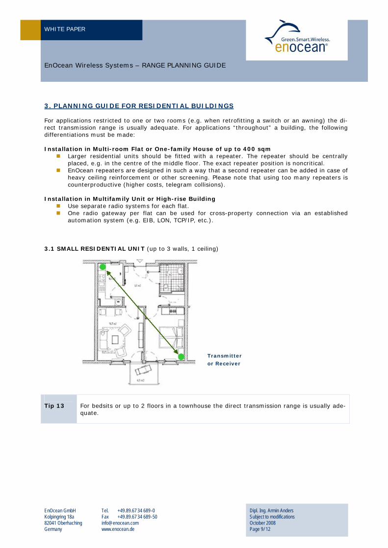
automation system (e.g. EIB, LON, TCP/IP, etc.). 3.1 SMALL RESIDENTIAL UNIT (up to 3 walls, 1 ceiling) Tip 13
For bedsits or up to 2 floors in a townhouse the direct transmission range is usually ade-quate.
Transmitter or Receiver
WHITE PAPER
EnOcean GmbH Kolpingring 18a 82041 Oberhaching Germany
Tel. +49.89.67 34 689-0 Fax +49.89.67 34 689-50 [email protected] www.enocean.de
Dipl. Ing. Armin Anders Subject to modifications October 2008 Page 10/ 12
EnOcean Wireless Systems – RANGE PLANNING GUIDE
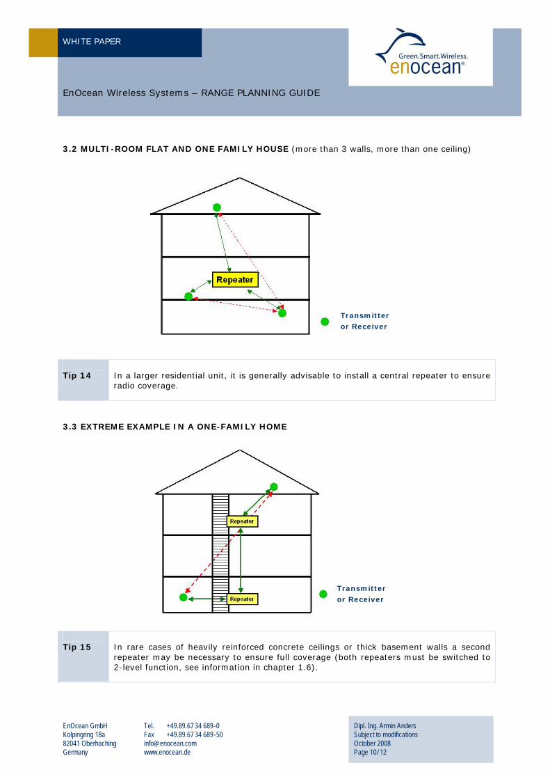
3.2 MULTI-ROOM FLAT AND ONE FAMILY HOUSE (more than 3 walls, more than one ceiling)
Tip 14
In a larger residential unit, it is generally advisable to install a central repeater to ensure radio coverage.
3.3 EXTREME EXAMPLE IN A ONE-FAMILY HOME
Tip 15
In rare cases of heavily reinforced concrete ceilings or thick basement walls a second repeater may be necessary to ensure full coverage (both repeaters must be switched to 2-level function, see information in chapter 1.6).
Transmitter or Receiver
Transmitter or Receiver
WHITE PAPER
EnOcean GmbH Kolpingring 18a 82041 Oberhaching Germany
Tel. +49.89.67 34 689-0 Fax +49.89.67 34 689-50 [email protected] www.enocean.de
Dipl. Ing. Armin Anders Subject to modifications October 2008 Page 11/ 12
EnOcean Wireless Systems – RANGE PLANNING GUIDE
U4. RADIO SYSTEM DEBUGGING The foregoing information on selecting the ideal place of installation for transmitters and receivers has been provided to ensure a smooth operation of the devices. However, if you still have some radio transmission problems, please refer to the following for troubleshooting:
Any radio system consists of a transmitter (Tx-DUT = transmitter device under test), a radio propa-gation path (Radio Path), and a receiver (Rx-DUT = receiver device under test). In case of insufficient coverage, also noticed as temporary malfunctions, please note that radio is not a magic and princi-pally only the following problems can occur:
1. Jammer present
2. Transmitter unit defective (Tx-DUT)
3. Receiver unit defective (Rx-DUT)
4. Range limit reached (Radio Path)
In the following please find a very easy guide to quickly identify one of those problems.
Test setup – What’s required?
1) Equipment in operation (Tx-DUT, Rx-DUT): Tx-DUT actuates Rx-DUT, the proper signal recep-tion has to be easily visible (e.g. light on/off)
2) 2 persons for testing (technical basic understanding)
3) 1 EPM radio level meter (please use EPM 100 Type BB, consider a reserve battery)
4) 1 REFERENCE RADIO SWITCH (tested at another place for proper range and function together with the mentioned EPM)
5) 2 mobile phones (for communication in case of separation walls are given)
Procedure 1 – JAMMER Test
Switch on the EPM: A jammer is present if the YELLOW or even GREEN field strength LED of the EPM flashes/shines constantly. Short impulses (< 1 sec) are not critical, can be signals from already in-stalled EnOcean transmitters or signals from other (allowed) radio systems.
a) If jamming only occurs next to receiver antenna: Remove low-power jammer (e.g. PC, tele-phone) at least 50 cm away from the EnOcean receiver antenna.
b) If jamming occurs all over the room: Remove high-power jammer. If removing is not possible you have to accept eventually strong range reduction (try to use repeaters).
Another easy indication for a high-power jammer is that the range between EPM and REFERENCE RADIO SWITCH is clearly less than 10 m line-of-sight at the jammed area.
Procedure 2 – TRANSMITTER UNIT Test
1. Person 1 remains at the transmitter unit place and operates the REFERENCE RADIO SWITCH consecutively and alternating to the probably defective transmitter unit Tx-DUT. If Tx-DUT is a sensor than operate the LRN pushbutton to transmit.
2. Person 2 moves away with the EPM level meter until the GREEN HI-signal lamp changes to the YELLOW LOW-signal lamp.
WHITE PAPER
EnOcean GmbH Kolpingring 18a 82041 Oberhaching Germany
Tel. +49.89.67 34 689-0 Fax +49.89.67 34 689-50 [email protected] www.enocean.de
Dipl. Ing. Armin Anders Subject to modifications October 2008 Page 12/ 12
EnOcean Wireless Systems – RANGE PLANNING GUIDE
If there is a significant range loss of the tested transmitter device Tx-DUT against the REFERENCE RADIO SWICH (it does not depend on one meter more or less), please change the transmitter unit.
Procedure 3 – RECEIVER UNIT Test
1. Person 1 remains at the receiving place with the EPM100 under the RECEIVING UNIT, keeps thereby the EPM in direction of the ceiling (it does not depend on one meter more or less)
2. Person 2 moves away at consecutively actuation of the transmitter Tx-DUT so far until Person 1 signalizes that the GREEN HI-signal lamp of the EPM changes to the YELLOW LOW-signal lamp.
If there is a significant range loss of the tested Receiver Unit Rx-DUT against the reference EPM (it does not depend on one meter more or less), please check
a) Receiver mounting position (antenna position) and
b) Receiver unit functionality (antenna, hardware, software).
Procedure 4 – RADIO PATH Test
If none of the upper mentioned failures has been identified, the problem cause should be in the radio propagation path. Please read Chapter 1 to 3 of this paper in detail and also consider the following major problem causes:
1) In practical installations you should have a reliable radio range of at least 10 m, even under worst case installation conditions. Otherwise please check for:
2) SCREENING: Massive objects made of metal, such as metallic separation walls and metal in-serted ceilings, massive wall reinforcements and the metal foil of heat insulations, reflect electromagnetic waves and thus create what is known as radio shadow. However singularized small metal studs, e.g. the metal studs of a gypsum dry wall, don’t show a recognizable screening.
3) METAL SEPARATION WALLS: It can be noticed that radio transmission actually works well with metal indoor separation walls. This happens through reflections: Walls made of metal or concrete reflect electromagnetic waves. The radio waves reach the next room or floor via a non metallic opening, e.g. a wooden door or an indoor glass window. But note that locally the radio range can be strongly reduced (dead spots).
4) Mounting an additional repeater at a suited location can easily provide an optional propaga-tion path.
0BDISCLAIMER
The information provided in this document describe typical features of the EnOcean radio transmis-sion system and should not be misunderstood as specified operating characteristics. No liability is assumed for errors and / or omissions. We reserve the right to make changes without prior notice. For the latest documentation visit the EnOcean website at www.enocean.com.