enhanced heap leaching: ii. applications - experts.com · enhanced heap leaching: ii. ... as mrds1...
TRANSCRIPT
Enhanced Heap Leaching: II. Applications
Shlomo Orr and Velimir Vesselinov
Abstract
In our 1st article (Orr, 2000), we investigated different flow and transport phenomena that could significantly reduce leaching recovery. The combination of such understanding with advanced flow and transport modeling establishes the link between cause and effect, thereby directing operators to optimal design and construction of new heaps. Modeling of flow and transport in heaps could also point to a unique change in application method or rate that would maximize leaching enhancement of an existing heap under existing situation and leaching history. The use of such a model is cost effective in that it can simulate multiple scenarios of alternative leaching enhancement methods. By simulating a large number of irrigation scenarios, such a model can point to optimal and/or most promising alternatives for a particular heap. Our simulations concentrate on the effect of changes in application rates and heap design on changes in flow paths and enhanced leaching recovery. Based on such simulations, an intelligent control agent such as MRDS1 could build a new representation of the complex heap leaching system, and by learning from historical data and current information, it could provide optimal management of heap leaching and heap rinsing.
Putting it all together: From Conceptual Models to Simulations
With the exception of film flow and precipitation/dissolution, all of the preferential flow
phenomena discussed above can be captured in a numerical model that is based on mass balance principles. We used a multiphase flow and transport model, FEHM - Finite Element Heat and Mass transport (developed by Los Alamos National Laboratories) to simulate flow and tracer transport in typical heaps. We examined two major types of hypothetical heaps: one is made of lifts of ore crushed and stacked uniformly, and one made of lifts of “run of mine” (ROM) constructed by successive dumping of blasted rocks, using trucks. For each heap type, uniformly stacked crushed ore and ROM, we adopted hydraulic parameters from published analyses of similar materials, and then perturbed these parameters about their mean values to reflect natural heterogeneity (the heterogeneity was somewhat exaggerated to emphasize the effect of heap structure on flow patterns within it. Though each heap is unique, the results show some patterns that provide insight into the general nature of flow and transport in heaps. The following Figures show simulated saturation, flow, and transport in different heaps under different conditions.
Figure 1 shows a cross section of saturation over time, up to 10.5 days from the start of solution application for the uniform heap. Figure 2 (a) and (b) shows saturation profiles during a leaching cycle of 20 days for the ROM heap. The simulations show “dry” zones within the heap throughout the cycle due to significant bypassing of the ore by the leach solution. Figures 3, 4, and 5 show transport of a tracer slug in a “uniform” heap under “high”, “medium”, and “low” application rates, respectively, while Figure 6 compares the different transport paths of the particles under the three different application rates. In particular, a close look at the high and medium flow rates (uppermost and middle pictures) reveals substantially different flow paths 1 MRDS stands for Multiple Resolution Decision-Support System, by Meystel et al., 2000.
triggered by different flow rates, while flow paths under the “low” application rate are only slightly different from those generated by “medium” rates. That is, a significant change in flow rates does not necessarily imply a substantial change in flow paths. This emphasizes the need in modeling to design changes in application rate that will maximize leaching efficiency. A judicious construction of a heap could enable leaching enhancement that by a careful management of application rates.
It should be kept in mind that our modeling demonstration is compatible with specific (though hypothetical) heaps. For all management purposes, modeling of certain heaps under leaching is site specific and could vary significantly from one heap to another, depending on their hydraulic properties and their specific construction and operation histories. Only with a careful evaluation of heap parameters and careful monitoring over a period of time could a modeler construct a model that resembles the hydraulic behavior of a specific heap.
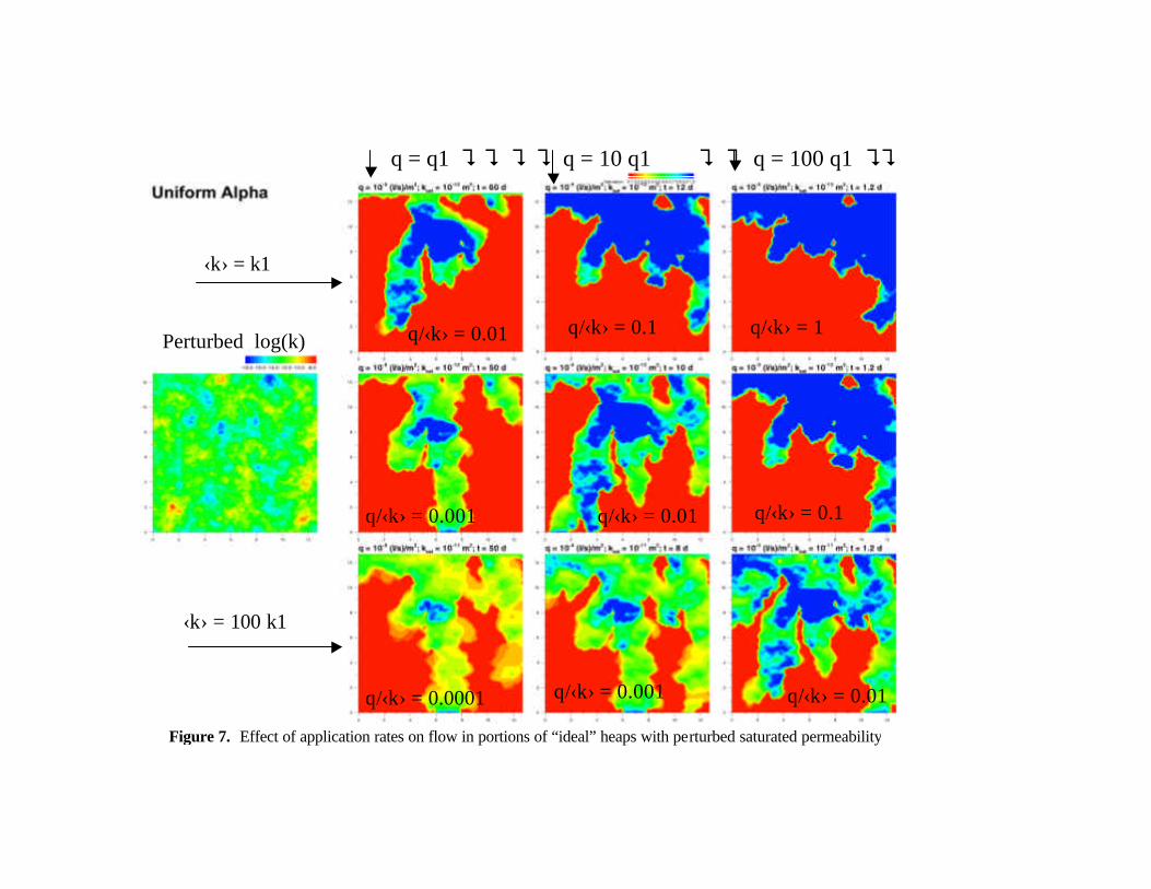
In order to further examine the effect of changes in application rates on changes in flow paths we took a closer look at the normalized application rate, expressed by the ratio of application rates to mean saturated permeability (q/?k?). Figures 7 and 8 show saturation profiles in square portions of ideal heaps (i.e., heaps constructed with no specific trend or anisotropy in mean permeability; also called “statistically homogeneous and isotropic”), under different q/k ratios. The “rows” consist of identical heap portions (with the same mean saturated permeability and same statistical structure) under different application rates, while the “columns” consist of identical application rates applied to similar heap portions (statistically identical) except for different mean saturated permeabilities. In Figure 7, only saturated permeability is perturbed, while in Figure 8, two inter-related parameters are perturbed - permeability and the pore size distribution parameter. Further, while Figure 7 represents a medium where saturated permeability and the pore size distribution are independent, in Figure 8, these parameters are functionally dependent on each other via scaling, based on the similarity theory (of Miller and Miller). This is reflected by the appearance of identical saturation profiles along the diagonal, implying that the only significant factor is the normalized application rate, q/?k?.
Summary and Recommendations Numerical modeling of flow and basic transport in a particular heap could provide
visualization of probable flow patterns and transport pathways, as well as a clear view of unleached zones, which provides the basis for possible remedies. A comprehensive reactive transport modeling could also provide predictions of overall production over time. Moreover, such a model can be used to evaluate the effect of changes in application rates, application distribution, and application methods on enhanced production. Knowledge of the geochemical and mineralogical composition of the heap would provide further optimization by implementing this knowledge in a comprehensive hydrogeochemical modeling.
The spatial distribution of both hydrologic and geochemical parameters to be used in such numerical models can be determined by field and laboratory tests (though, this is not a trivial task), as well as documented heap history – from construction to data collection and processing. A reactive transport model could use these parameters together with known (monitored) solution composition and application rates to simulate copper production. Geophysical mapping such as HRR (high resolution resistivity) and basic hydro-chemical data could be used to calibrate and then validate a model. Monitoring of flow and chemistry in all drain outlets should be
incorporated in the calibration process, as well as model validation. The validation (i.e., proving the ability of the model to predict flow and transport) completes the construction of the model as a predictive tool, capable of simulating multiple flow and transport scenarios resulting from different application methods and practices. Validation of such models can be done first in the laboratory in column experiments. The ultimate validation however, is in the field using experimental small heaps or actual heaps, and including dissection of the stockpiles. It should be emphasized that one-dimensional column tests that focus on production only, are likely to be misleading on a heap scale in three-dimensions. The advantage of physically-based models is their ability to upscale predictions from 1D column experiments in the laboratory to experimental 3D heaps and to actual operational heaps. Due to natural heterogeneity of hydraulic and geochemical properties of heaps, calibration of model parameters in a deterministic sense is practically done through averaging and uncertainty reduction, which ultimately helps to maximize leaching recovery. The main advantage of a working model is its ability to run multiple scenarios (of different application rates, schedules, and spatial distributions), enabling operators to choose the most promising ones.
Under large uncertainty in hydraulic and geochemical properties, however, even the best physically-based model may not be able to provide reliable predictions. We suggest an additional tool used in optimized control systems, such as MRDS (Multiresolution Decision Support system; e.g., Meystel et al., 2001). Briefly, this is an intelligent control agent that learns from existing models and from historical and current data, particularly, continuous HRR and chemistry data, and dynamically builds (and rebuilds) a new representation (or a model) of the complex heap leaching system in real time; the learning and the ever-improving model are oriented towards a goal (maximum production or maximum rinsing, with minimum cost), and are attached to dynamic optimization that provides optimal heap management, either in the form of advice to the operators or by automatic adjustment of solution flow. Further description of the control system is beyond the scope of this paper.
If sprinklers are being used, the investigation should also include drop sizes, coverage uniformity, drop scattering, and their impact on the heap surfaces. Drip irrigation (by pressure emitters) is attractive since it significantly reduces evaporation losses and environmental pollution by spray, and it enables more physical control and survey on heap surfaces during solution applications. However, drip emitters were originally designed to localize flow, rather than spread uniformly; therefore, a dense grid is required (say, about 1 foot spacing between emitters) in order to maximize leaching uniformity (and efficiency), which increases cost. Further, drip emitters are sensitive to partial clogging by solids and microorganisms that feed on kerosene residues in the leach solution; hence, some kind of a bio-filtration system has to be added. Since bio-filtration of leach solution should be considered anyway, modified drip emitters could become the ultimate application tool.
As a last resort, when production is severely declined, it may be worthwhile to try to mix, rearrange, or break the rock fragments that constitute the “old” heap or dump. This can be done partly mechanically (say, by a giant ripper shank), or in a more invasive way, by a skillful and careful use of propellants. Explosives have been used in some heaps for that purpose, but the resulting blasts are too aggressive, and could easily tear a liner. Scraping the uppermost weathered material from the heap’s crest (particularly fines generated by long periods of sprinkling of leach solution) could also enhance leaching by reducing fingered flow.
The significance of curing or pretreatment with concentrated acid with and without surfactants should be revisited. In particular, one needs to determine the optimal composition of

the solution used for curing (that is, to find how concentrated and/or pure the solution should be compared to just water), and cost-effectiveness of surfactants. Pre-treating the ore directly on a conveyor belt before placement on the heap is preferable to pretreatment after stacking. Optimal agglomeration should also be revisited, particularly in view of the limited durability of agglomeration under continuous leaching.
Finally, we suggest laboratory tests that will determine the effect of organic carbon (originating from kerosene used in the solvent extraction process) on surface tension, rock wettability, and overall leaching. Like surfactants, some organic compounds are known to inhibit microbial growth (Horowitz, personal communication). Therefore, for bioleaching purposes it would be beneficial to eliminate both surfactants and organic carbon. Controlled laboratory experiments could provide most of the answers. Such experiments may be able to reveal the combined effects of minute quantities of surfactants and organic carbon in solution (both raffinate and diluted “clean” sulfuric acid) on wettability and capillary forces within and around ore fragments.
Conclusions 1. Understanding of the physical processes of flow and transport within a particular heap or
dump is needed for optimal leaching management. Such understanding can be greatly enhanced by auditing heap history of construction and management, combined with basic monitoring and data collection.
2. Essential data include geophysical mapping, flow and chemistry at all drain outlets, and in-situ measurements of hydraulic properties.
3. Based on the insight and hydrogeochemical properties obtained through heap history, data collection, and field tests, a preliminary flow and transport model of the heap can be constructed and calibrated. Together with continuous monitoring, the model could, in principle, be used as a management tool to maximize the production of copper or gold.
4. For all heaps, particularly where the distributions of hydraulic and geochemical properties are not well characterized, we suggest an additional tool – a Multiresolution Decision Support system (MRDS), originating from methods of Intelligent Control. The unique learning and multi- level search algorithms of the MRDS enable it to learn from existing models and from historical and current data. The representation (or model) created by this learning, together with continuous flow of HRR and chemistry information enables the MRDS to optimize heap leaching in real time.
REFERENCES
Meystel, A. and J. Albus, Intelligent Systems: Architecture, Design, Control, Wiley, 2001 ISBN: 0-471-19374-7

Figure 1. Simulation of flow in heaps constructed by uniform stacking of crushed and ore
2.5 Days
5 Days
7.5 Days
10.5 Days
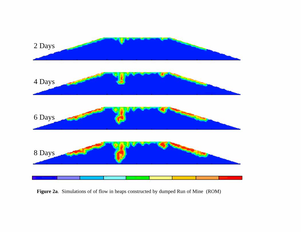
Figure 2a. Simulations of of flow in heaps constructed by dumped Run of Mine (ROM)
2 Days
4 Days
6 Days
8 Days
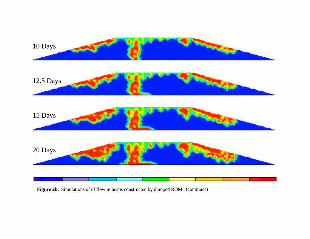
10 Days
12.5 Days
15 Days
20 Days
Figure 2b. Simulations of of flow in heaps constructed by dumped ROM (continues)
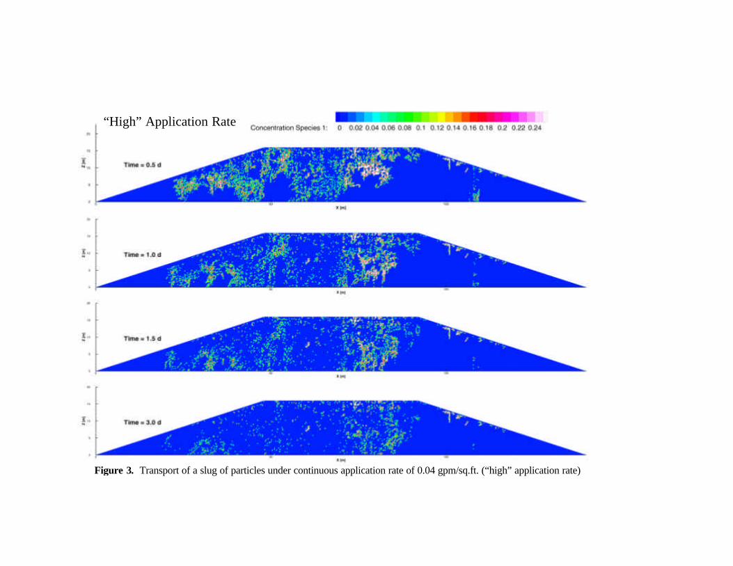
“High” Application Rate
Figure 3. Transport of a slug of particles under continuous application rate of 0.04 gpm/sq.ft. (“high” application rate)

“Medium” Application Rate
Figure 4. Transport of a slug of particles under continuous application rate of 0.004 gpm/sq.ft. (“medium” application rate)

“Low” Application Rate
Figure 5. Transport of a slug of particles under continuous application rate of 0.0004 gpm/sq.ft. (“low” application rate)
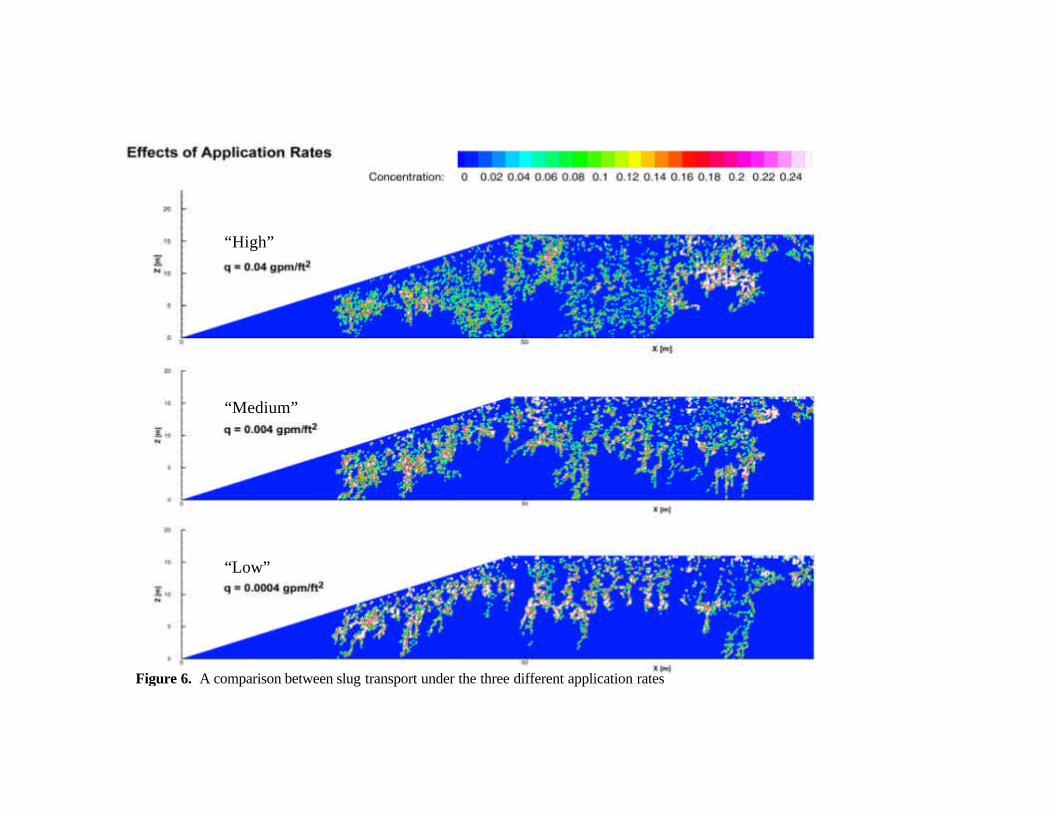
Figure 6. A comparison between slug transport under the three different application rates
“High”
“Medium”
“Low”
q = q1 ? ? ? ? q = 10 q1 ? ? q = 100 q1 ? ?
Figure 7. Effect of application rates on flow in portions of “ideal” heaps with perturbed saturated permeability
‹k› = k1
‹k› = 100 k1
Perturbed log(k)
q/‹k› = 0.1
q/‹k› = 0.1 q/‹k› = 1 q/‹k› = 0.01
q/‹k› = 0.01
q/‹k› = 0.01
q/‹k› = 0.001
q/‹k› = 0.001 q/‹k› = 0.0001

? q = q1 ? ? ? ? q = 10 q1 ? ? q = 100 q1 ? ???
Figure 8. Effect of application rates on flow in portions of “ideal” heaps with perturbed mean saturated permeability, k, and pore-size-distribution parameter, a (related to k through the “scaling”).
q/‹k› = 1
q/‹k› = 0.1
q/‹k› = 0.1
q/‹k› = 0.01
q/‹k› = 0.01
q/‹k› = 0.01
q/‹k› = 0.001
q/‹k› = 0.001 q/‹k› = 0.0001
‹k› = Constant
Perturbed log(k) and log (a)