english version 1
TRANSCRIPT
Thermocouple Application
2
Emergency Shipping ServiceIn emergency situations L.H. Marshall Co. will ship smallquantities of in-stock thermocouples within 24 hours at noadditional charge.
Special Purpose ThermocouplesL.H. Marshall Co. has been making thermocouples in answering questions of application and to developsince 1927 with emphasis on types used worldwide for custom thermocouples tailored to your own specialthe taking of molten nonferrous metal temperatures. needs. Give us a call, or send your specifications forToday our expertise extends even further into foundry, prompt, courteous attention. Call toll-free 1-800-THER-plastic injection molding and other industrial and com- MOC. Or FAX (614) 294-0297. In Ohio, call (614)mercial thermocouple applications. 294-6433 collect. L. H. Marshall Company, Box 02226,Our knowledge in all phases of thermocouple design Columbus, Ohio 43202.and manufacture is available to you; both to assist you
Although some of the thermocouples listed above can beused at higher temperatures than those shown, these aregenerally considered to be maximum reliable operatingtemperatures.
Type J (Iron vs. Constantan) Can be used protected orunprotected. Reducing atmosphere recommended. Iron wireoxidizes rapidly above 1000° F.Type K (Chromel-Alumel*) Recommended for oxidizingatmospheres. Should be used in suitable protection tubewhen in a reducing or sulphurous atmosphere.Type T (Copper-Constantan) Useable in oxidizing, re-ducing or inert atmospheres.
Type E (Chromel*-Constantan) Oxidizing atmospheresrecommended. Highest EMF of common base metalthermocouples.Type R (Platinum vs. Platinum 13% Rhodium) Oxidizingatmosphere recommended. Should be protected withceramic protection tube. Higher EMF output than Type S.Type S (Platinum vs. Platinum 10% Rhodium) Samegeneral conditions as Type R.Type B (Platinum 6% Rhodium vs. Platinum 30% Rhod-ium) Same general conditions as Type R & S. EMF outputis lower than Type R & S.Type C (Tungsten 26% Rhenium vs. Tungsten 5%Rhenium) For use in vacuum or inert gas applications.
*Chromel-Alumel trade name Hoskins Mfg. Co.
Limits of ErrorANSI Type Wire Alloys TemperatureRange ºF Standard Special
JIron ( + ) vs.
Constantan ( - )32 to 530
530 to 1400± 4° F
± 3/4%± 2° F
\± 3/8 %
KChromel ( + ) vs.
Alumel ( - )32 to 530
530 to 2300± 4°F
± 3/4 %± 2°F
± 3/8%
TCopper ( + ) vs.Constantan ( - )
- 300 to - 75-150 to -75- 75 to 200200 to 700
± 2%
± 1 1/2° F± 3/4%
± 1%± 1%
± 3/4° F± 3/8%
EChromel ( + ) vs.Constantan ( - )
32 to 600600 to 1600
± 3° F± 1/2%
RPlatinum ( - ) vs.
Pt. 13% Rhodium ( + )32 to 1000
1000 to 2700± 5° F± 1/2%
± 2 1/2° F± 1/4%
SPlatinum ( - ) vs.
Pt. 10% Rhodium( + )32 to1000
1000 to 2700± 5° F± 1/2%
± 2 1/2° F± 1/4%
BPt. 6% Rhodium ( - )vs. Pt. 30% Rh ( + ) 1600 to 3100 ± 1/2%
CTungsten 26% Rhenium ( - )
vs. Tungsten 5% Rhenium ( + ) 800 to 4200 ± 1 %
3
Thermometer SpecificationsTemperature Range
Display
Accuracy
Resolution
IndicationOperating RangeAccuracy with Time
Temperature Drift
Probe Connection
Storage Temperature
Normal Mode Rejection
Common Mode Rejection
-328° F to + 2498° F(- 200° C to + 1370° C) 0.30" LCD ± 1° F, ± 0. 10° F rdg High: 0.2°F, 0.1°C Low: 1°F, 1°C °F / °C selectable 0° to 50° C 90 days: add ± 0.05% rdg 1 year: add 0.1% rdg zero: ± 2µ V° C span: ± 0.02% / °C Standard mini-connector Type K-20° C to + 70° C 50 db at 50 or 60 Hz 140 db at 50 or 60 Hz
Maximum Common ModeVoltage MeasurementTechnique Linearization
Reference JunctionStability withTemperature
Input ResistanceUpdate RateBattery
Battery Life
Warranty
1000 VAC, ± 2000 V peak
Dual-slope A/D conversion100% digital. Typically100 segments depending onrange selected.
Thermocouple:± 0.7°C from 5°C to 45°C±1.3°F from 41°F to 113°F
Thermocouple: 13M Ω1 reading / second typical
9 volt transistor NEDA#1604I n excess of 1200continuous hours forthermocouple. Lowbattery indicator.1 year
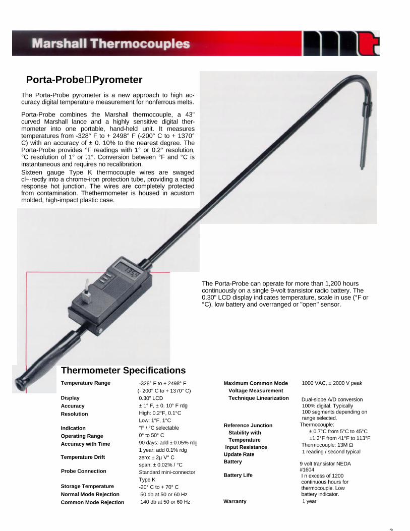
The Porta-Probe can operate for more than 1,200 hourscontinuously on a single 9-volt transistor radio battery. The0.30" LCD display indicates temperature, scale in use (°F or°C), low battery and overranged or "open" sensor.
Porta-Probe PyrometerThe Porta-Probe pyrometer is a new approach to high ac-curacy digital temperature measurement for nonferrous melts.
Porta-Probe combines the Marshall thermocouple, a 43"curved Marshall lance and a highly sensitive digital ther-mometer into one portable, hand-held unit. It measurestemperatures from -328° F to + 2498° F (-200° C to + 1370°C) with an accuracy of ± 0. 10% to the nearest degree. ThePorta-Probe provides °F readings with 1° or 0.2° resolution,°C resolution of 1° or .1°. Conversion between °F and °C isinstantaneous and requires no recalibration.Sixteen gauge Type K thermocouple wires are swagedcl~-rectly into a chrome-iron protection tube, providing a rapidresponse hot junction. The wires are completely protectedfrom contamination. Thethermometer is housed in acustommolded, high-impact plastic case.
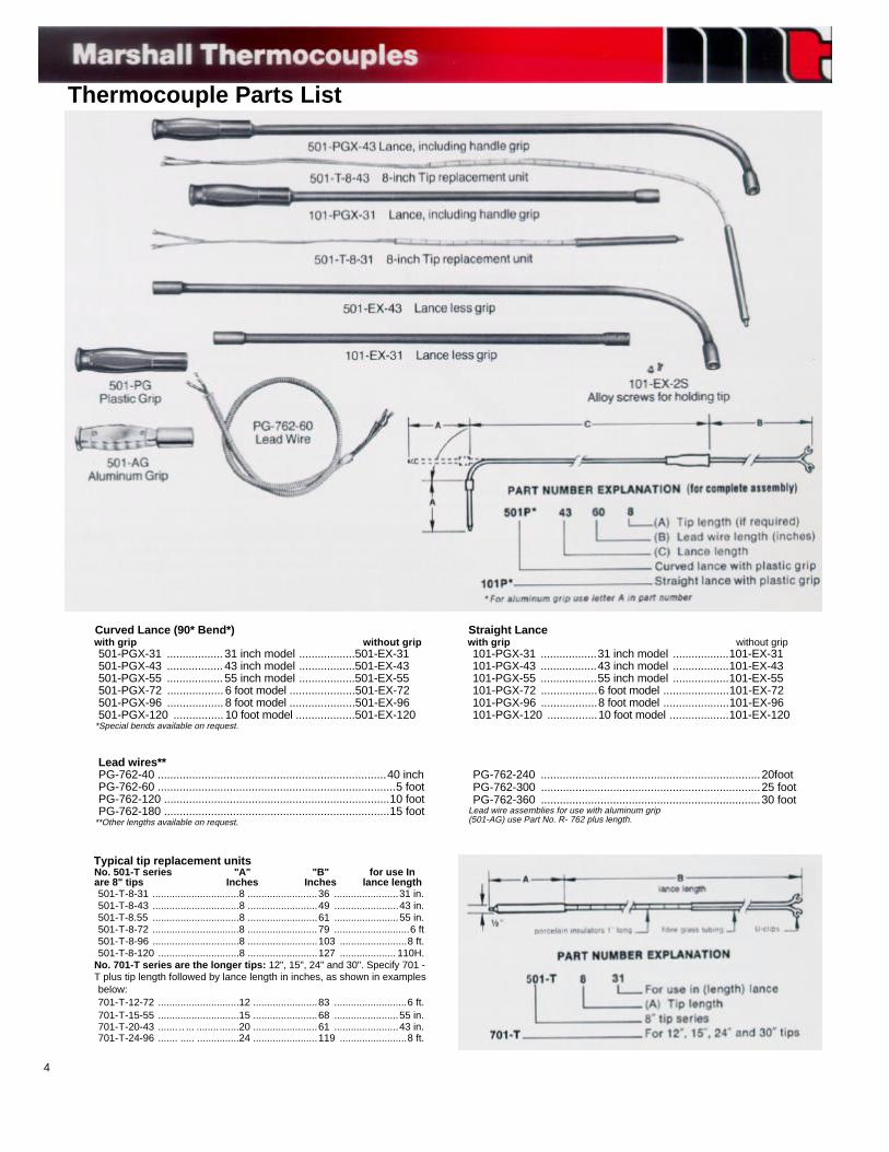
Thermocouple Parts List
Curved Lance (90* Bend*)with grip without grip501-PGX-31 .................. 31 inch model ..................501-EX-31501-PGX-43 .................. 43 inch model ..................501-EX-43501-PGX-55 .................. 55 inch model ..................501-EX-55501-PGX-72 .................. 6 foot model .....................501-EX-72501-PGX-96 .................. 8 foot model .....................501-EX-96501-PGX-120 ................ 10 foot model ...................501-EX-120
*Special bends available on request.
Straight Lancewith grip without grip101-PGX-31 ..................31 inch model ..................101-EX-31101-PGX-43 ..................43 inch model ..................101-EX-43101-PGX-55 ..................55 inch model ..................101-EX-55101-PGX-72 ..................6 foot model .....................101-EX-72101-PGX-96 ..................8 foot model .....................101-EX-96101-PGX-120 ................10 foot model ...................101-EX-120
Lead wires**PG-762-40 .........................................................................40 inchPG-762-60 ............................................................................5 footPG-762-120 ........................................................................10 footPG-762-180 ........................................................................15 foot
**Other lengths available on request.
PG-762-240 ......................................................................20footPG-762-300 ......................................................................25 footPG-762-360 ......................................................................30 foot
Lead wire assemblies for use with aluminum grip(501-AG) use Part No. R- 762 plus length.
Typical tip replacement unitsNo. 501-T series "A" "B" for use Inare 8" tips Inches Inches lance length501-T-8-31 ...............................8 .........................36 .......................31 in.501-T-8-43 ...............................8 .........................49 .......................43 in.501-T-8.55 ...............................8 .........................61 .......................55 in.501-T-8-72 ...............................8 .........................79 ...........................6 ft501-T-8-96 ...............................8 .........................103 ........................8 ft.501-T-8-120 .............................8 .........................127 .................... 110H.
No. 701-T series are the longer tips: 12", 15", 24" and 30". Specify 701 -T plus tip length followed by lance length in inches, as shown in examplesbelow:701-T-12-72 .............................12 .......................83 ..........................6 ft.701-T-15-55 .............................15 .......................68 .......................55 in.701-T-20-43 ....... .. ... ...............20 .......................61 .......................43 in.701-T-24-96 ....... ..... ...............24 .......................119 ........................8 ft.
4
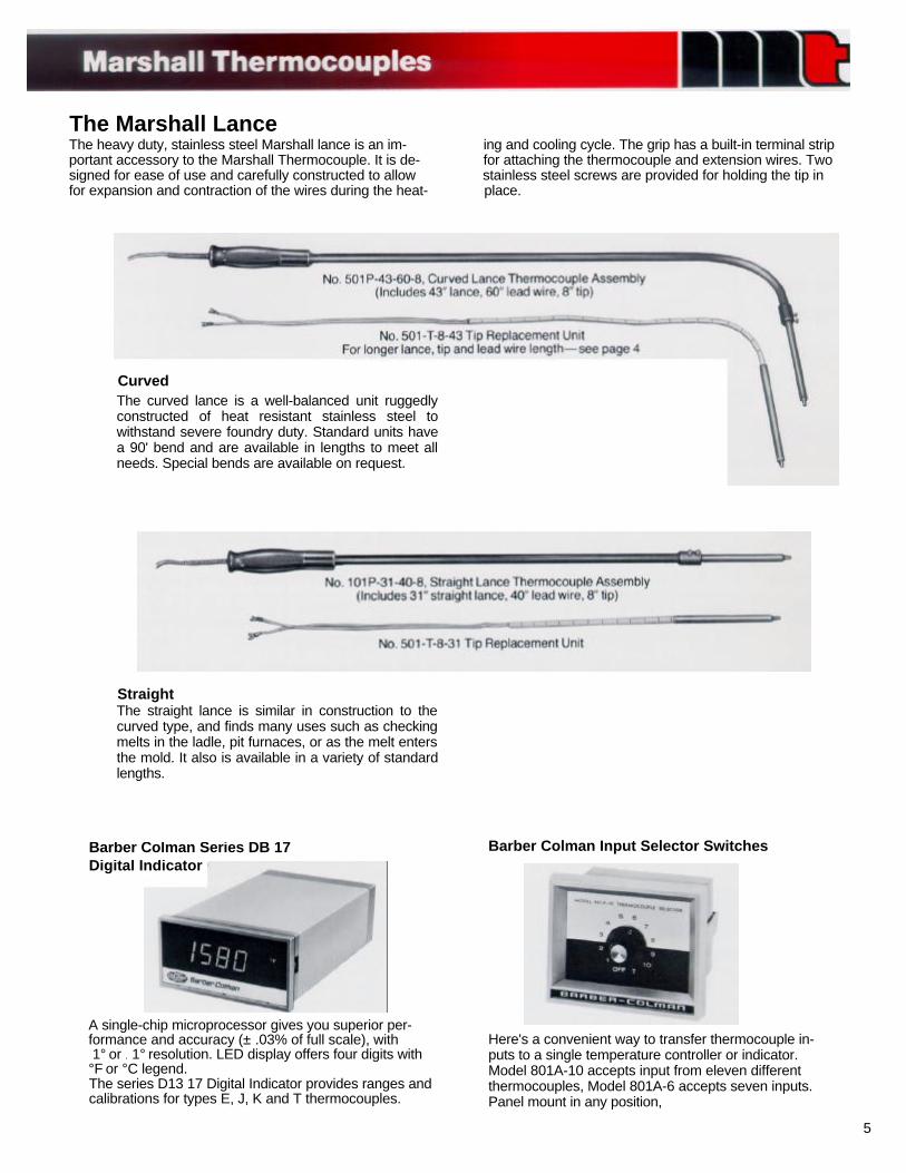
The Marshall LanceThe heavy duty, stainless steel Marshall lance is an im- ing and cooling cycle. The grip has a built-in terminal stripportant accessory to the Marshall Thermocouple. It is de- for attaching the thermocouple and extension wires. Twosigned for ease of use and carefully constructed to allow stainless steel screws are provided for holding the tip infor expansion and contraction of the wires during the heat- place.
CurvedThe curved lance is a well-balanced unit ruggedlyconstructed of heat resistant stainless steel towithstand severe foundry duty. Standard units havea 90' bend and are available in lengths to meet allneeds. Special bends are available on request.
StraightThe straight lance is similar in construction to thecurved type, and finds many uses such as checkingmelts in the ladle, pit furnaces, or as the melt entersthe mold. It also is available in a variety of standardlengths.
Barber Colman Series DB 17Digital Indicator
Barber Colman Input Selector Switches
A single-chip microprocessor gives you superior per-formance and accuracy (± .03% of full scale), with 1° or . 1° resolution. LED display offers four digits with°F or °C legend.The series D13 17 Digital Indicator provides ranges andcalibrations for types E, J, K and T thermocouples.
Here's a convenient way to transfer thermocouple in-puts to a single temperature controller or indicator.Model 801A-10 accepts input from eleven differentthermocouples, Model 801A-6 accepts seven inputs.Panel mount in any position,
5
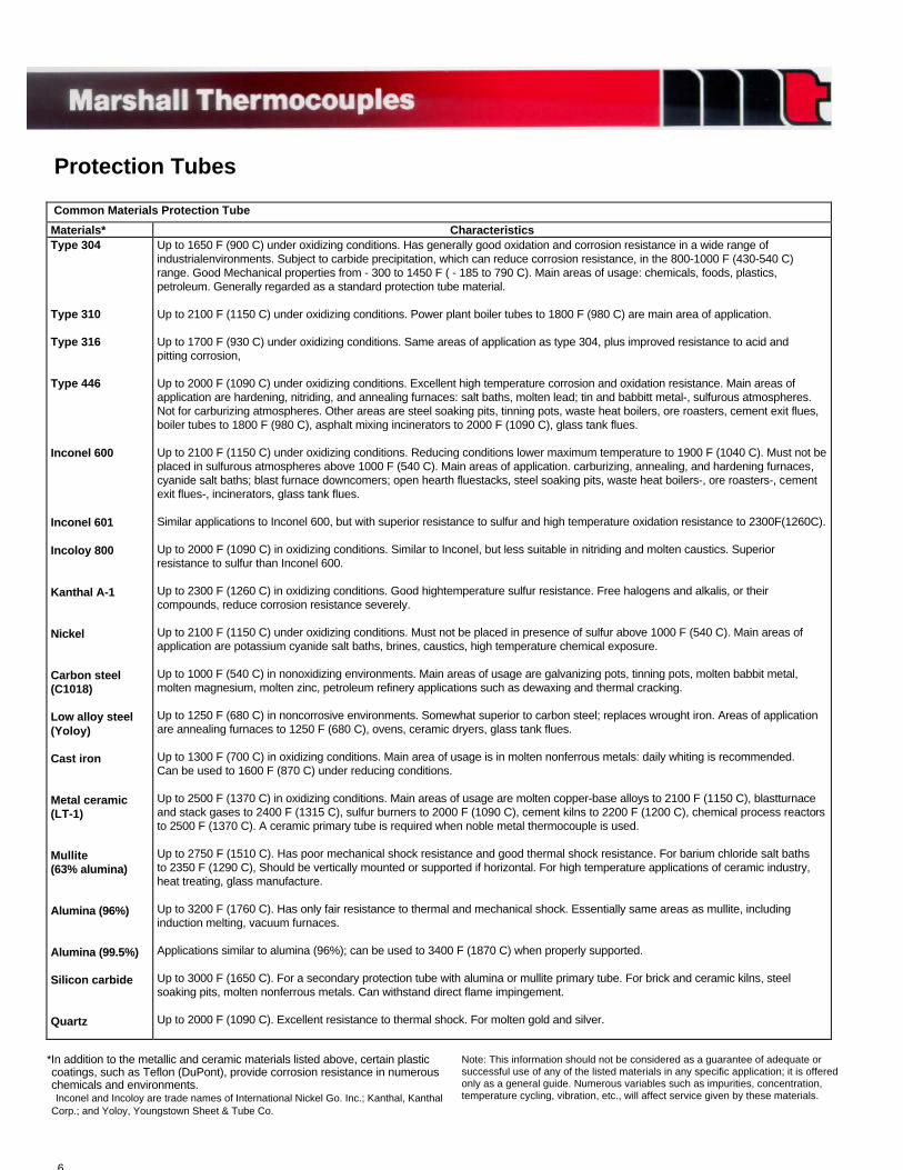
Protection Tubes
Common Materials Protection Tube
Materials* CharacteristicsType 304
Type 310
Type 316
Type 446
Inconel 600
Inconel 601
Incoloy 800
Kanthal A-1
Nickel
Carbon steel(C1018)
Low alloy steel(Yoloy)
Cast iron
Metal ceramic(LT-1)
Mullite(63% alumina)
Alumina (96%)
Alumina (99.5%)
Silicon carbide
Quartz
Up to 1650 F (900 C) under oxidizing conditions. Has generally good oxidation and corrosion resistance in a wide range ofindustrialenvironments. Subject to carbide precipitation, which can reduce corrosion resistance, in the 800-1000 F (430-540 C)range. Good Mechanical properties from - 300 to 1450 F ( - 185 to 790 C). Main areas of usage: chemicals, foods, plastics,petroleum. Generally regarded as a standard protection tube material.
Up to 2100 F (1150 C) under oxidizing conditions. Power plant boiler tubes to 1800 F (980 C) are main area of application.
Up to 1700 F (930 C) under oxidizing conditions. Same areas of application as type 304, plus improved resistance to acid andpitting corrosion,
Up to 2000 F (1090 C) under oxidizing conditions. Excellent high temperature corrosion and oxidation resistance. Main areas ofapplication are hardening, nitriding, and annealing furnaces: salt baths, molten lead; tin and babbitt metal-, sulfurous atmospheres.Not for carburizing atmospheres. Other areas are steel soaking pits, tinning pots, waste heat boilers, ore roasters, cement exit flues,boiler tubes to 1800 F (980 C), asphalt mixing incinerators to 2000 F (1090 C), glass tank flues.
Up to 2100 F (1150 C) under oxidizing conditions. Reducing conditions lower maximum temperature to 1900 F (1040 C). Must not beplaced in sulfurous atmospheres above 1000 F (540 C). Main areas of application. carburizing, annealing, and hardening furnaces,cyanide salt baths; blast furnace downcomers; open hearth fluestacks, steel soaking pits, waste heat boilers-, ore roasters-, cementexit flues-, incinerators, glass tank flues.
Similar applications to Inconel 600, but with superior resistance to sulfur and high temperature oxidation resistance to 2300F(1260C).
Up to 2000 F (1090 C) in oxidizing conditions. Similar to Inconel, but less suitable in nitriding and molten caustics. Superiorresistance to sulfur than Inconel 600.
Up to 2300 F (1260 C) in oxidizing conditions. Good hightemperature sulfur resistance. Free halogens and alkalis, or theircompounds, reduce corrosion resistance severely.
Up to 2100 F (1150 C) under oxidizing conditions. Must not be placed in presence of sulfur above 1000 F (540 C). Main areas ofapplication are potassium cyanide salt baths, brines, caustics, high temperature chemical exposure.
Up to 1000 F (540 C) in nonoxidizing environments. Main areas of usage are galvanizing pots, tinning pots, molten babbit metal,molten magnesium, molten zinc, petroleum refinery applications such as dewaxing and thermal cracking.
Up to 1250 F (680 C) in noncorrosive environments. Somewhat superior to carbon steel; replaces wrought iron. Areas of applicationare annealing furnaces to 1250 F (680 C), ovens, ceramic dryers, glass tank flues.
Up to 1300 F (700 C) in oxidizing conditions. Main area of usage is in molten nonferrous metals: daily whiting is recommended.Can be used to 1600 F (870 C) under reducing conditions.
Up to 2500 F (1370 C) in oxidizing conditions. Main areas of usage are molten copper-base alloys to 2100 F (1150 C), blastturnaceand stack gases to 2400 F (1315 C), sulfur burners to 2000 F (1090 C), cement kilns to 2200 F (1200 C), chemical process reactorsto 2500 F (1370 C). A ceramic primary tube is required when noble metal thermocouple is used.
Up to 2750 F (1510 C). Has poor mechanical shock resistance and good thermal shock resistance. For barium chloride salt bathsto 2350 F (1290 C), Should be vertically mounted or supported if horizontal. For high temperature applications of ceramic industry,heat treating, glass manufacture.
Up to 3200 F (1760 C). Has only fair resistance to thermal and mechanical shock. Essentially same areas as mullite, includinginduction melting, vacuum furnaces.
Applications similar to alumina (96%); can be used to 3400 F (1870 C) when properly supported.
Up to 3000 F (1650 C). For a secondary protection tube with alumina or mullite primary tube. For brick and ceramic kilns, steelsoaking pits, molten nonferrous metals. Can withstand direct flame impingement.
Up to 2000 F (1090 C). Excellent resistance to thermal shock. For molten gold and silver.
6
*In addition to the metallic and ceramic materials listed above, certain plasticcoatings, such as Teflon (DuPont), provide corrosion resistance in numerouschemicals and environments.Inconel and Incoloy are trade names of International Nickel Go. Inc.; Kanthal, Kanthal
Corp.; and Yoloy, Youngstown Sheet & Tube Co.
Note: This information should not be considered as a guarantee of adequate orsuccessful use of any of the listed materials in any specific application; it is offeredonly as a general guide. Numerous variables such as impurities, concentration,temperature cycling, vibration, etc., will affect service given by these materials.
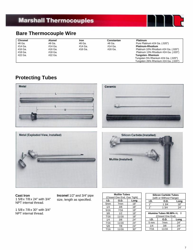
Bare Thermocouple WireChromel Alumel Iron Constantan Platinum#8 Ga. #8 Ga. #8 Ga. #8 Ga. Pure Platinum #24 Ga. (.020")#14 Ga. #14 Ga. #14 Ga. #14 Ga. Platinum-Rhodium#16 Ga. #16 Ga. #16 Ga. #16 Ga. Platinum 10% Rhodium #24 Ga. (.020")#18 Ga. #18 Ga. Platinum 13% Rhodium #24 Ga. (.020")#22 Ga. #22 Ga. Tungsten- Rhenium Tungsten 5% Rhenium #24 Ga. (.020")
Tungsten 26% Rhenium #24 Ga. (.020")
Protecting Tubes
Cast Iron1 5/8 x 7/8 x 24" with 3/4"NPT internal thread.
1 5/8 x 7/8 x 30" with 3/4"NPT internal thread.
Inconel 1/2" and 3/4" pipesize, length as specified.
Mullite Tubes(Closed One End, Gas Tight)I.D. O.D. Long
5mm 7mm 18"1/4 3/8 18"5/16 7/16 18"3/8 1/2 18"7/16 11/16 18"1/4 3/8 24"7/16 11/16 24"5/8 7/8 24"7/16 11/16 30"
Alumina Tubes 99.98% AL 0(Closed One End)
I.D. O.D. Long5 mm 7mm 24"1/4 3/8 24"7/16 11/16 24"
Silicon Carbide Tubes(with or Without Flange)
I.D. O.D. Long 1" 1 3/4 18" 1" 1 3/4 24"
7
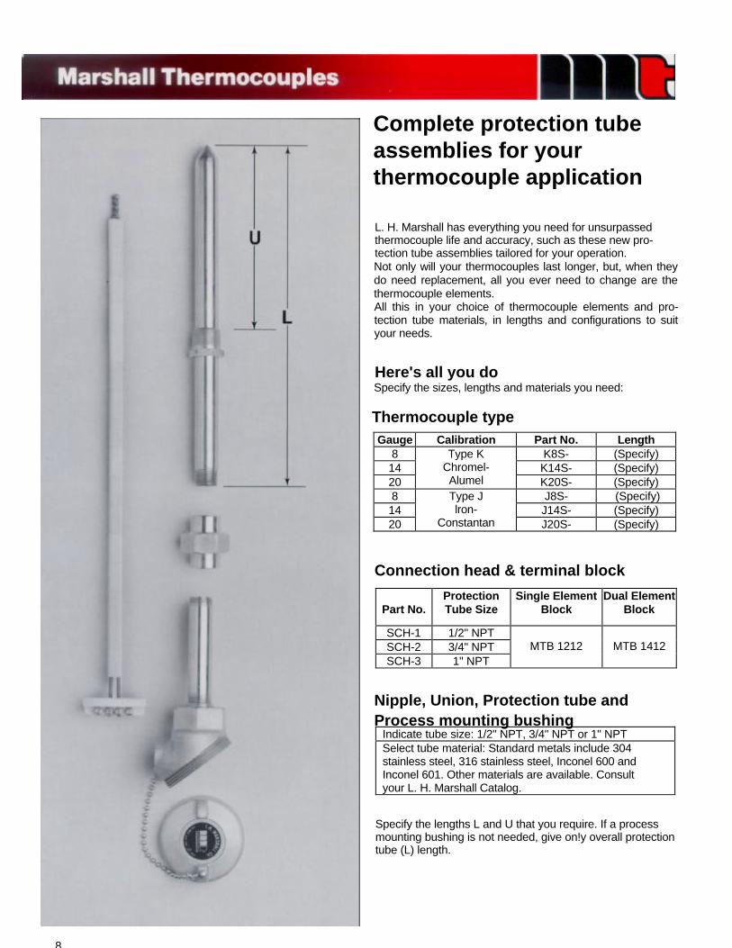
Specify the lengths L and U that you require. If a processmounting bushing is not needed, give on!y overall protectiontube (L) length.
Indicate tube size: 1/2" NPT, 3/4" NPT or 1" NPTSelect tube material: Standard metals include 304stainless steel, 316 stainless steel, Inconel 600 andInconel 601. Other materials are available. Consultyour L. H. Marshall Catalog.
Nipple, Union, Protection tube andProcess mounting bushing
Part No.ProtectionTube Size
Single ElementBlock
Dual ElementBlock
SCH-1 1/2" NPTSCH-2 3/4" NPTSCH-3 1" NPT
MTB 1212 MTB 1412
Connection head & terminal block
Gauge Calibration Part No. Length8 K8S- (Specify)14 K14S- (Specify)20
Type KChromel-Alumel K20S- (Specify)
8 J8S- (Specify)14 J14S- (Specify)20
Type Jlron-
Constantan J20S- (Specify)
Thermocouple type
Here's all you doSpecify the sizes, lengths and materials you need:
L. H. Marshall has everything you need for unsurpassedthermocouple life and accuracy, such as these new pro-tection tube assemblies tailored for your operation.Not only will your thermocouples last longer, but, when theydo need replacement, all you ever need to change are thethermocouple elements.All this in your choice of thermocouple elements and pro-tection tube materials, in lengths and configurations to suityour needs.
8
Complete protection tubeassemblies for yourthermocouple application
9
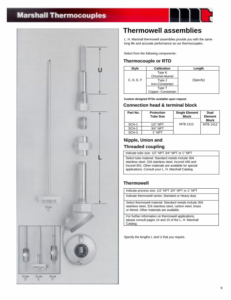
Specify the lengths L and U that you require.
Indicate process size: 1/2" NPT 3/4" NPT or 1" NPT
Indicate thermowell series: Standard or Heavy-duty
Select thermowell material: Standard metals include 304stainless steel, 316 stainless steel, carbon steel, brassor Monel. Other materials are available.
For further information on thermowell applications,please consult pages 14 and 15 of the L. H. MarshallCatalog.
Thermowell
Indicate tube size: 1/2" NPT 3/4" NPT or 1" NPT
Select tube material: Standard metals include 304stainless steel, 316 stainless steel, Inconel 446 andInconel 601. Other materials are available for specialapplications. Consult your L. H. Marshall Catalog.
Nipple, Union andThreaded coupling
Single ElementBlock
Part No. ProtectionTube Size
DualElement
BlockSCH-1 1/2" NPTSCH-2 3/4" NPTSCH-3 1" NPT
MTB 1212 MTB 1412
Connection head & terminal blockCustom designed RTDs available upon request
Style Calibration LengthType K
Chromel-AlumelType J
Iron-ConstantanC, D, E, F
Type TCopper- Constantan
(Specify)
Thermocouple or RTD
Select from the following components:
L. H. Marshall thermowell assemblies provide you with the samelong life and accurate performance as our thermocouples.
Thermowell assemblies
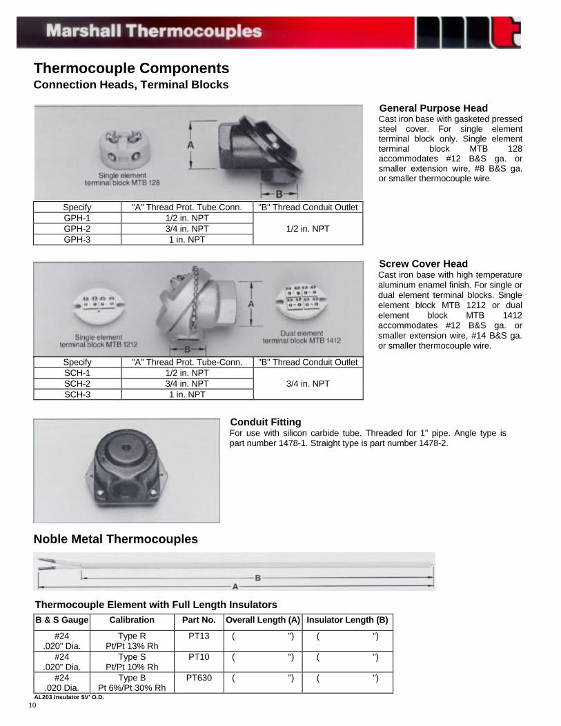
Thermocouple ComponentsConnection Heads, Terminal Blocks
Noble Metal Thermocouples
General Purpose HeadCast iron base with gasketed pressedsteel cover. For single elementterminal block only. Single elementterminal block MTB 128accommodates #12 B&S ga. orsmaller extension wire, #8 B&S ga.or smaller thermocouple wire.
Screw Cover HeadCast iron base with high temperaturealuminum enamel finish. For single ordual element terminal blocks. Singleelement block MTB 1212 or dualelement block MTB 1412accommodates #12 B&S ga. orsmaller extension wire, #14 B&S ga.or smaller thermocouple wire.
Conduit FittingFor use with silicon carbide tube. Threaded for 1" pipe. Angle type ispart number 1478-1. Straight type is part number 1478-2.
Thermocouple Element with Full Length InsulatorsB & S Gauge Calibration Part No. Overall Length (A) Insulator Length (B)
#24.020" Dia.
Type RPt/Pt 13% Rh
PT13 ( ") ( ")
#24.020" Dia.
Type SPt/Pt 10% Rh
PT10 ( ") ( ")
#24.020 Dia.
Type BPt 6%/Pt 30% Rh
PT630 ( ") ( ")
AL203 Insulator $V' O.D.
Specify "A" Thread Prot. Tube Conn. "B" Thread Conduit OutletGPH-1 1/2 in. NPTGPH-2 3/4 in. NPT 1/2 in. NPTGPH-3 1 in. NPT
Specify "A" Thread Prot. Tube-Conn. "B" Thread Conduit OutletSCH-1 1/2 in. NPTSCH-2 3/4 in. NPT 3/4 in. NPTSCH-3 1 in. NPT
10
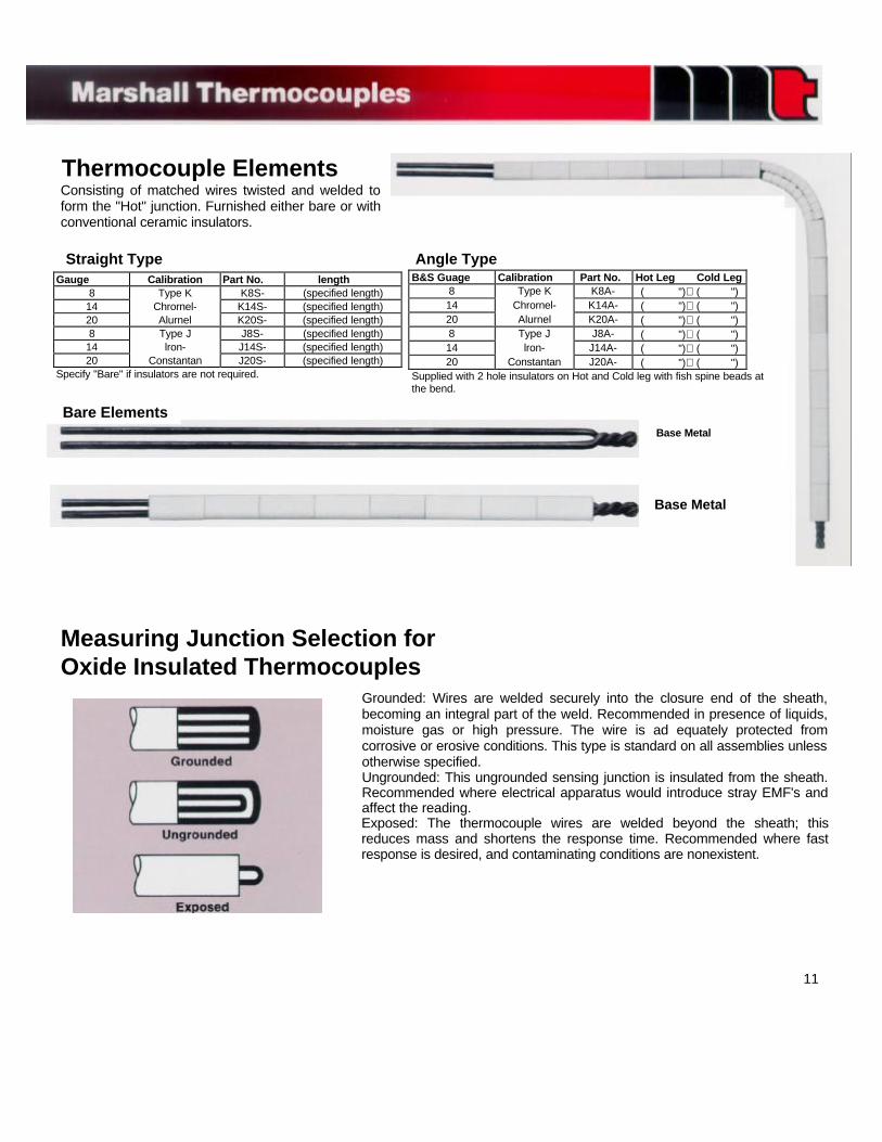
Thermocouple ElementsConsisting of matched wires twisted and welded toform the "Hot" junction. Furnished either bare or withconventional ceramic insulators.
Straight Type Angle TypeGauge Calibration Part No. length
8 Type K K8S- (specified length)14 Chrornel- K14S- (specified length)20 Alurnel K20S- (specified length)8 Type J J8S- (specified length)
14 lron- J14S- (specified length)20 Constantan J20S- (specified length)
Specify "Bare" if insulators are not required.
B&S Guage Calibration Part No. Hot Leg Cold Leg8 Type K K8A- ( ")( ")14 Chrornel- K14A- ( ")( ")20 Alurnel K20A- ( ")( ")8 Type J J8A- ( ")( ")14 lron- J14A- ( ")( ")20 Constantan J20A- ( ")( ")
Supplied with 2 hole insulators on Hot and Cold leg with fish spine beads atthe bend.
Bare ElementsBase Metal
Base Metal
Measuring Junction Selection forOxide Insulated Thermocouples
Grounded: Wires are welded securely into the closure end of the sheath,becoming an integral part of the weld. Recommended in presence of liquids,moisture gas or high pressure. The wire is ad equately protected fromcorrosive or erosive conditions. This type is standard on all assemblies unlessotherwise specified.Ungrounded: This ungrounded sensing junction is insulated from the sheath.Recommended where electrical apparatus would introduce stray EMF's andaffect the reading.Exposed: The thermocouple wires are welded beyond the sheath; thisreduces mass and shortens the response time. Recommended where fastresponse is desired, and contaminating conditions are nonexistent.
11
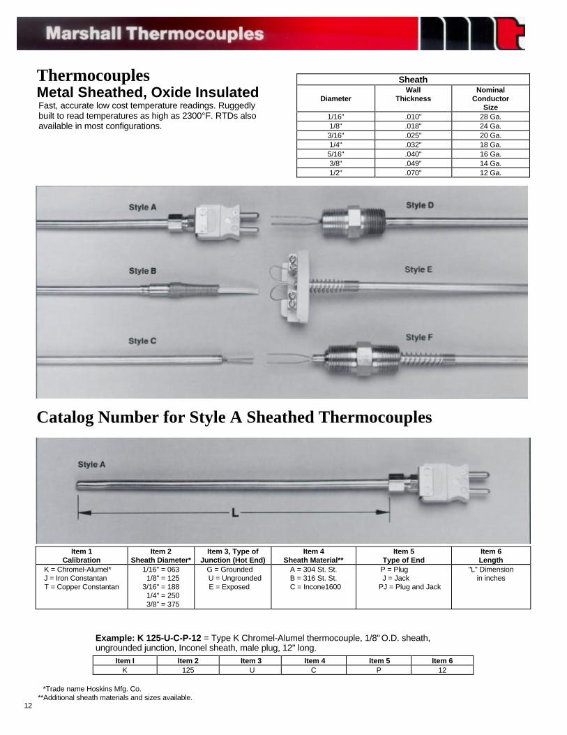
ThermocouplesMetal Sheathed, Oxide InsulatedFast, accurate low cost temperature readings. Ruggedlybuilt to read temperatures as high as 2300°F. RTDs alsoavailable in most configurations.
Sheath
DiameterWall
ThicknessNominal
ConductorSize
1/16" .010" 28 Ga.1/8" .018" 24 Ga.3/16" .025" 20 Ga.1/4" .032" 18 Ga.5/16" .040" 16 Ga.3/8" .049" 14 Ga.1/2" .070" 12 Ga.
Catalog Number for Style A Sheathed Thermocouples
Item 1Calibration
Item 2Sheath Diameter*
Item 3, Type ofJunction (Hot End)
Item 4Sheath Material**
Item 5Type of End
Item 6Length
K = Chromel-Alumel* J = Iron Constantan
T = Copper Constantan
1/16" = 063 1/8" = 1253/16" = 188 1/4" = 250 3/8" = 375
G = Grounded U = Ungrounded
E = Exposed
A = 304 St. St.B = 316 St. St.
C = Incone1600
P = Plug J = Jack
PJ = Plug and Jack
"L" Dimensionin inches
*Trade name Hoskins Mfg. Co.**Additional sheath materials and sizes available.
12
Example: K 125-U-C-P-12 = Type K Chromel-Alumel thermocouple, 1/8" O.D. sheath,ungrounded junction, Inconel sheath, male plug, 12" long.
Item I Item 2 Item 3 Item 4 Item 5 Item 6K 125 U C P 12
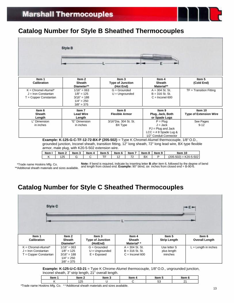
Catalog Number for Style B Sheathed Thermocouples
Item 1Calibration
Item 2Sheath
Diameter**
Item 3Type of Junction
(Hot End)
Item 4Sheath
Material**
Item 5(Cold End)
K = Chromel-Alumel*J = Iron Constantan
T = Copper Constantan
1/16" = 0631/8" = 1253/16" = 1881/4" = 2503/8" = 375
G = Grounded U = Ungrounded
A = 304 St. St.B = 316 St. St.
C = lnconel 600
TF = Transition Fitting
Item 6SheathLength
Item 7Lead Wire
Length
Item 8Flexible Armor
Item 9Plug, Jack, Bothor Spade Lugs
Item 10Type of Extension Wire
L" Dimensionin inches
"E" Dimensionin inches
3/16"Dia. 304 St. St.BX Type
P = PlugJ = Jack
PJ = Plug and JackLCC = # 8 Spade Lug &1/2" Conduit Connector
See Pages9-12
Example: K-125-G-C-TF-12-72-BX-P (205-502) = Type K Chromel-Alumel thermocouple, 1/8" O.D.,grounded junction, Inconel sheath, transition fitting, 12" long sheath, 72" long lead wire, BX type flexiblearmor, male plug, with K20-5-502 extension wire.
Item I Item 2 Item 3 Item 4 Item 5 Item 6 Item 7 Item 8 Item 9 Item 10K 125 G C TF 12 72 BX P (205-502) = K20-5-502
*Trade name Hoskins Mfg. Co.**Additional sheath materials and sizes available.
Note: If bend is required, indicate by inserting letter B after item 6, followed by the degree of bendand length from closed end. Example: 90° bend, six inches from closed end = B-90-6.
Catalog Number for Style C Sheathed Thermocouples
Item 1Calibration
Item 2Sheath
Diameter*
Item 3Type of Junction
(HotEnd)
Item 4Sheath
Material* *
Item 5Strip Length
Item 6Overall Length
K = Chromel-Alumel* J = Iron Constantan T = Copper Constantan
1/16" = 0631/8" = 1253/16" = 1881/4" = 2503/8" = 375
G = Grounded U = Ungrounded
E = Exposed
A = 304 St. St.B = 316 St. St.
C = Inconel 600
Use letter Splus lengthininches
L = Length in inches
Example: K-125-U-C-S3-21 = Type K Chrome-Alumel thermocouple, 1/8" O.D., ungrounded junction,Inconel sheath, 3" strip length, 21" overall length.
Item 1 Item 2 Item 3 Item 4 Item 5 Item 6K 125 U C S3 21
*Trade name Hoskins Mfg. Co. * *Additional sheath materials and sizes available.13
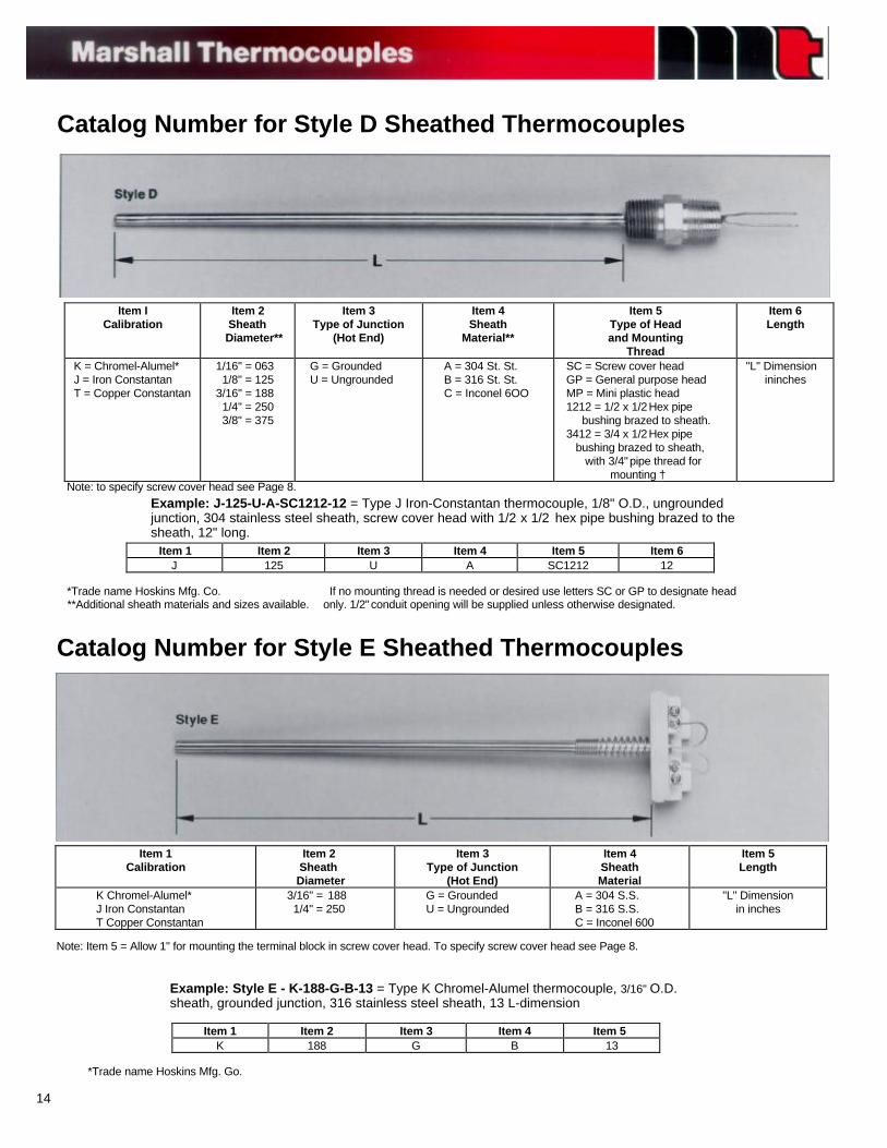
Catalog Number for Style D Sheathed Thermocouples
Note: to specify screw cover head see Page 8.
Example: J-125-U-A-SC1212-12 = Type J Iron-Constantan thermocouple, 1/8" O.D., ungroundedjunction, 304 stainless steel sheath, screw cover head with 1/2 x 1/2 hex pipe bushing brazed to thesheath, 12" long.
*Trade name Hoskins Mfg. Co.**Additional sheath materials and sizes available.
If no mounting thread is needed or desired use letters SC or GP to designate headonly. 1/2" conduit opening will be supplied unless otherwise designated.
Catalog Number for Style E Sheathed Thermocouples
Item ICalibration
Item 2 Sheath Diameter**
Item 3Type of Junction
(Hot End)
Item 4Sheath
Material**
Item 5Type of Headand Mounting
Thread
Item 6Length
K = Chromel-Alumel* J = Iron Constantan T = Copper Constantan
1/16" = 0631/8" = 125
3/16" = 1881/4" = 2503/8" = 375
G = Grounded U = Ungrounded
A = 304 St. St. B = 316 St. St. C = Inconel 6OO
SC = Screw cover head GP = General purpose head MP = Mini plastic head 1212 = 1/2 x 1/2 Hex pipe bushing brazed to sheath. 3412 = 3/4 x 1/2 Hex pipe bushing brazed to sheath, with 3/4" pipe thread for mounting †
"L" Dimensionininches
Item 1 Item 2 Item 3 Item 4 Item 5 Item 6 J 125 U A SC1212 12
Item 1Calibration
Item 2 Sheath Diameter
Item 3Type of Junction
(Hot End)
Item 4SheathMaterial
Item 5Length
K Chromel-Alumel* J Iron Constantan T Copper Constantan
3/16" = 188 1/4" = 250
G = Grounded U = Ungrounded
A = 304 S.S. B = 316 S.S. C = Inconel 600
"L" Dimensionin inches
Note: Item 5 = Allow 1" for mounting the terminal block in screw cover head. To specify screw cover head see Page 8.
Example: Style E - K-188-G-B-13 = Type K Chromel-Alumel thermocouple, 3/16" O.D.sheath, grounded junction, 316 stainless steel sheath, 13 L-dimension
Item 1 Item 2 Item 3 Item 4 Item 5K 188 G B 13
*Trade name Hoskins Mfg. Go.
14
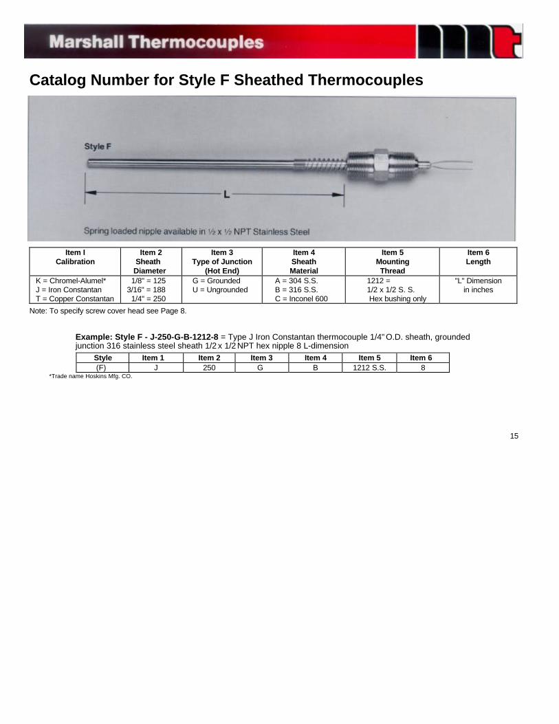
Catalog Number for Style F Sheathed Thermocouples
*Trade name Hoskins Mfg. CO.
15
Item ICalibration
Item 2 Sheath Diameter
Item 3Type of Junction
(Hot End)
Item 4SheathMaterial
Item 5MountingThread
Item 6Length
K = Chromel-Alumel* J = Iron Constantan T = Copper Constantan
1/8" = 125 3/16" = 188 1/4" = 250
G = Grounded U = Ungrounded
A = 304 S.S. B = 316 S.S. C = Inconel 600
1212 = 1/2 x 1/2 S. S. Hex bushing only
"L" Dimensionin inches
Note: To specify screw cover head see Page 8.
Example: Style F - J-250-G-B-1212-8 = Type J Iron Constantan thermocouple 1/4" O.D. sheath, groundedjunction 316 stainless steel sheath 1/2 x 1/2 NPT hex nipple 8 L-dimension Style Item 1 Item 2 Item 3 Item 4 Item 5 Item 6 (F) J 250 G B 1212 S.S. 8
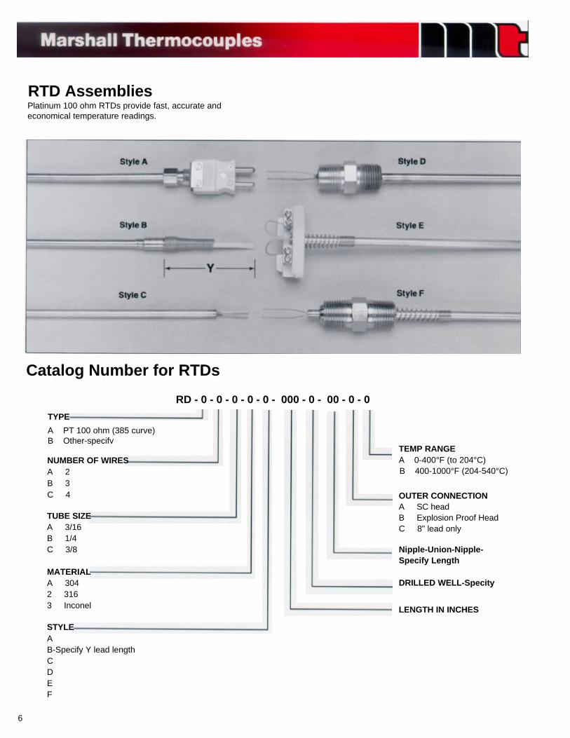
RTD AssembliesPlatinum 100 ohm RTDs provide fast, accurate andeconomical temperature readings.
Catalog Number for RTDs
RD - 0 - 0 - 0 - 0 - 0 - 000 - 0 - 00 - 0 - 0
STYLEAB-Specify Y lead lengthCDEF
MATERIALA 3042 3163 Inconel
TUBE SIZEA 3/16B 1/4C 3/8
NUMBER OF WIRESA 2B 3C 4
TYPE
A PT 100 ohm (385 curve)B Other-specify
LENGTH IN INCHES
DRILLED WELL-Specity
Nipple-Union-Nipple-Specify Length
OUTER CONNECTIONA SC headB Explosion Proof HeadC 8" lead only
TEMP RANGEA 0-400°F (to 204°C)B 400-1000°F (204-540°C)
6
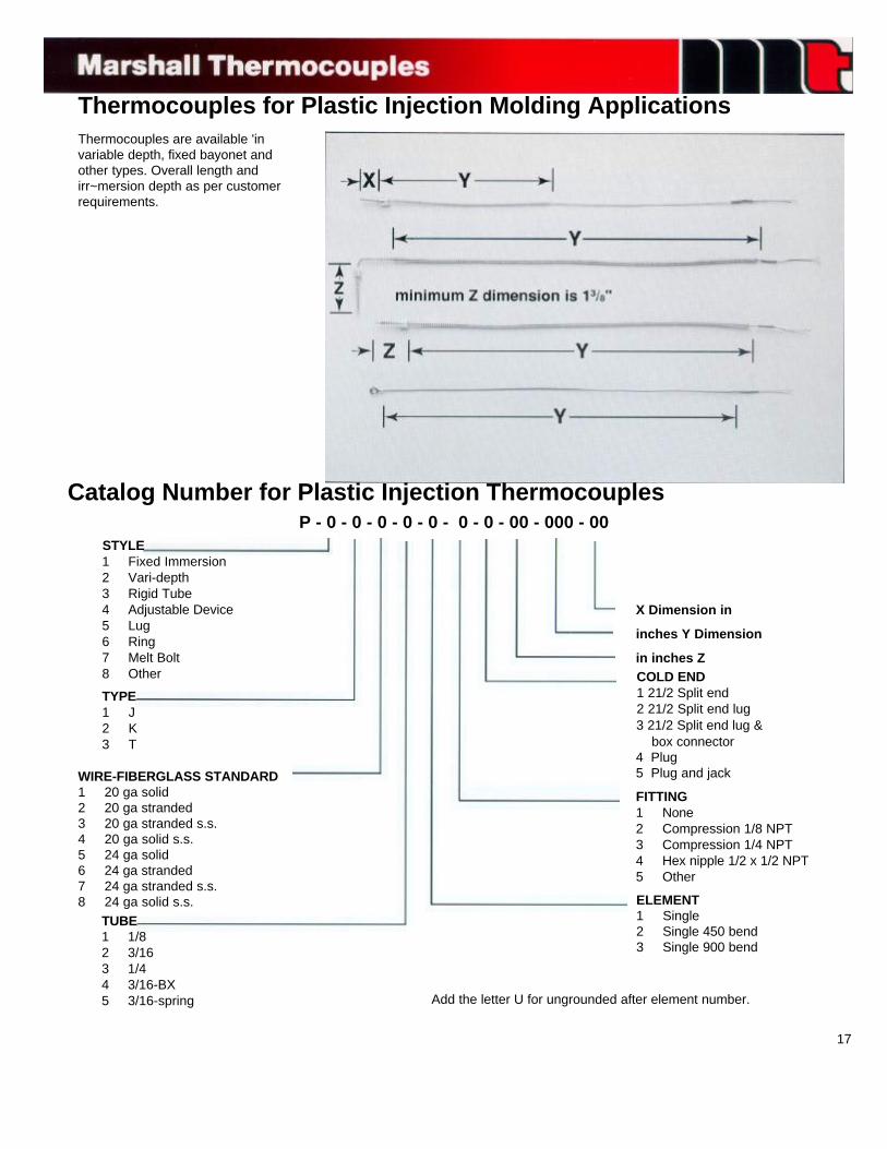
Thermocouples for Plastic Injection Molding ApplicationsThermocouples are available 'invariable depth, fixed bayonet andother types. Overall length andirr~mersion depth as per customerrequirements.
Catalog Number for Plastic Injection ThermocouplesP - 0 - 0 - 0 - 0 - 0 - 0 - 0 - 00 - 000 - 00
STYLE1 Fixed Immersion2 Vari-depth3 Rigid Tube4 Adjustable Device5 Lug6 Ring7 Melt Bolt8 Other
TYPE1 J2 K3 T
WIRE-FIBERGLASS STANDARD1 20 ga solid2 20 ga stranded3 20 ga stranded s.s.4 20 ga solid s.s.5 24 ga solid6 24 ga stranded7 24 ga stranded s.s.8 24 ga solid s.s.
TUBE1 1/82 3/163 1/44 3/16-BX5 3/16-spring Add the letter U for ungrounded after element number.
ELEMENT1 Single2 Single 450 bend3 Single 900 bend
FITTING1 None2 Compression 1/8 NPT3 Compression 1/4 NPT4 Hex nipple 1/2 x 1/2 NPT5 Other
COLD END1 21/2 Split end2 21/2 Split end lug3 21/2 Split end lug & box connector4 Plug5 Plug and jack
X Dimension in
inches Y Dimension
in inches Z
17
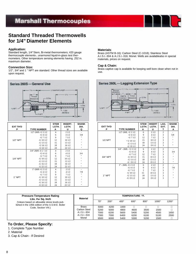
Standard Threaded Thermowellsfor 1/4" Diameter Elements
Application:Standard length, 1/4" Stem, Bi-metal thermometers; #20 gaugethermocouple elements-, unarmored liquid-in-glass test ther-mometers. Other temperature sensing elements having .252 in.maximum diameter.
Connection Size:1/2", 3/4" and 1 " NPT are standard. Other thread sizes are availableupon request.
Materials :Brass (ASTM B-16): Carbon Steel (C-1018); Stainless SteelA.I.S.I.-304 & A.I.S.I.-316; Monel. Wells are availablealso in specialmaterials, prices on request.
Cap & Chain:Brass captive cap is available for keeping well bore clean when not inuse.
EXT TH'DP TYPE NUMBER
STEM LGTH. A
INSERTLGTH.
U
LAG.EXT.
T
SHANKDIA.
A
1/2 NPT
1/2"-260L -U 2 1/2 -U 4 1/2 -U 7 1/2
- U 10 1/2 -U 13 1/2
-U 19 1/2
6912151824
2 1/24 1/27 1/210 1/213 1/219 1/2
233333
- 5/8 " " " "
3/4" NPT
3/4" - 260L - U 2 1/2 -U 4 1/2 -U 7 1/2 -U 10 1/2 -U 13 1/2 -U 19 1/2
6912151824
2 1/24 1/27 1/2
10 1/2 13 1/2 19 1/2
233333
-3/4""""
1" NPT
I" - 260L -U 2 1/2 -U 4 1/2 -U 7 1/2 -U 10 1/2 -U 13 1/2
-U 19 1/2
692 151824
2 1/24 1/27 1/2
10 1/213 1/219 1/2
233333
-7/8""""
EXT TH'DP TYPE NUMBER
STEM LGTH. A
INSERT.LGTH.
U
SHANKDIA.
Q
1/2" NPT
1/2"-260S -U 2 1/2 -U 4 1/2 -U 7 1/2 -U 10 1/2 -U 13 1/2 -U 16 1/2 -U 22 1/2
46912151824
2 1/24 1/27 1/210 1/213 1/216 1/222 1/2
-5/8"""""
1/4" NPT
3/4"-260S -U 2 1/2 -U 4 1/2
-U 7 1/2 -U 10 1/2
-U 13 1/2 -U 16 1/2
-U 22 1/2
46912151824
2 1/24 1/27 1/2
10 1/213 1/216 1/222 1/2
- 3/4 " " " " "
1" NPT
1"-260S -U 2 1/2 -U 4 1/2 -U 7 1/2 -U 10 1/2 -U 13 1/2 -U 16 1/2 -U 22 1/2
46912151824
2 1/2 4 1/2 7 1/210 1/213 1/216 1/2
22 1/2
-7/8"""""
To Order, Please Specify:1. Complete Type Number2. Material3. Cap & Chain - If Desired
8
TEMPERATURE -°°F.Material
70° 200° 400° 600° 800° 1000° 1200°
BrassCarbon SteelA.I.S.I.-304A.I.S.I.-316
Monel
5000 4200 1000 5200 5000 4800 4600 3500 1500
7000 6200 5600 5400 5200 4500 1650 7000 7000 6400 6200 6100 5100 25006500 6000 5400 5300 5200 1500
Pressure-Temperature RatingLbs. Per Sq. Inch
(Values based on allowable stress levels pub-lished in the 1956 edition of the A.S.M.E. Boiler
Code, Section VIII.)
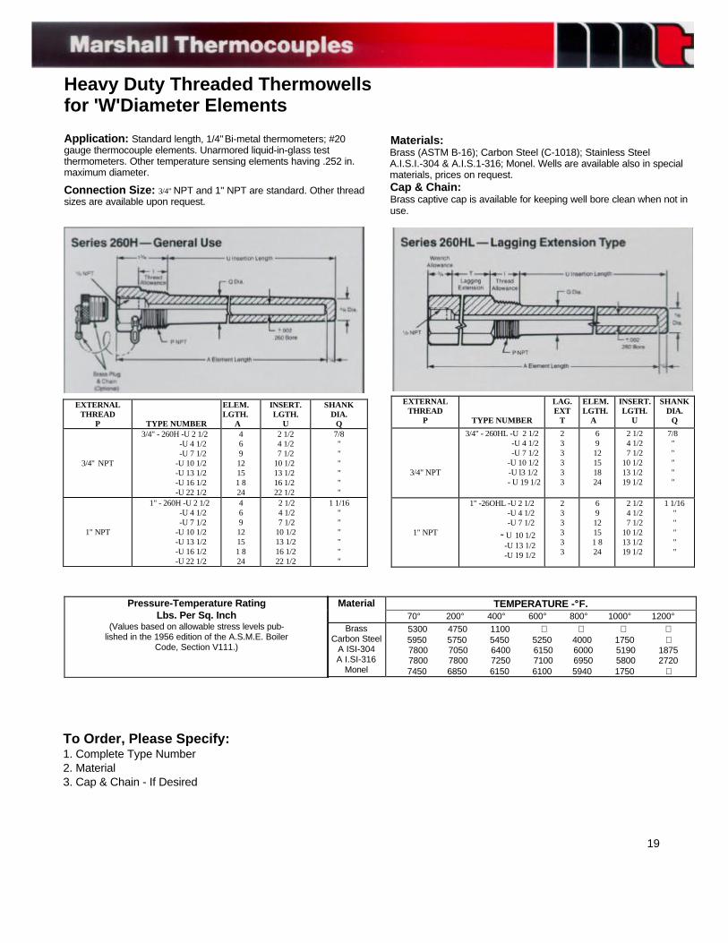
Heavy Duty Threaded Thermowellsfor 'W'Diameter Elements
Application: Standard length, 1/4" Bi-metal thermometers; #20gauge thermocouple elements. Unarmored liquid-in-glass testthermometers. Other temperature sensing elements having .252 in.maximum diameter.
Connection Size: 3/4" NPT and 1" NPT are standard. Other threadsizes are available upon request.
Materials:Brass (ASTM B-16); Carbon Steel (C-1018); Stainless SteelA.I.S.I.-304 & A.I.S.1-316; Monel. Wells are available also in specialmaterials, prices on request.Cap & Chain:Brass captive cap is available for keeping well bore clean when not inuse.
EXTERNALTHREAD
P TYPE NUMBER
LAG.EXT
T
ELEM. LGTH. A
INSERT.LGTH.
U
SHANKDIA.
Q
3/4" NPT
3/4" - 260HL -U 2 1/2 -U 4 1/2 -U 7 1/2 -U 10 1/2 -U l3 1/2
- U 19 1/2
233333
6912151824
2 1/24 1/27 1/2
10 1/2 13 1/2 19 1/2
7/8 " " " " "
1" NPT
1" -26OHL -U 2 1/2 -U 4 1/2 -U 7 1/2
- U 10 1/2 -U 13 1/2 -U 19 1/2
233333
6912151 824
2 1/24 1/27 1/2
10 1/2 13 1/2 19 1/2
1 1/16"""""
EXTERNALTHREAD
P TYPE NUMBER
ELEM.LGTH. A
INSERT.LGTH.
U
SHANKDIA.
Q
3/4" NPT
3/4" - 260H -U 2 1/2 -U 4 1/2 -U 7 1/2 -U 10 1/2 -U 13 1/2 -U 16 1/2 -U 22 1/2
46912151 824
2 1/24 1/27 1/2
10 1/2 13 1/2 16 1/2 22 1/2
7/8""""""
1" NPT
1" - 260H -U 2 1/2 -U 4 1/2 -U 7 1/2 -U 10 1/2 -U 13 1/2 -U 16 1/2 -U 22 1/2
46912151 824
2 1/2 4 1/2 7 1/210 1/213 1/216 1/222 1/2
1 1/16""""""
Pressure-Temperature RatingLbs. Per Sq. Inch
(Values based on allowable stress levels pub-lished in the 1956 edition of the A.S.M.E. Boiler
Code, Section V111.)
To Order, Please Specify:1. Complete Type Number2. Material3. Cap & Chain - If Desired
19
TEMPERATURE -°°F.Material70° 200° 400° 600° 800° 1000° 1200°
BrassCarbon Steel
A ISI-304A I.SI-316
Monel
5300 4750 1100 5950 5750 5450 5250 4000 1750
7800 7050 6400 6150 6000 5190 1875 7800 7800 7250 7100 6950 5800 27207450 6850 6150 6100 5940 1750
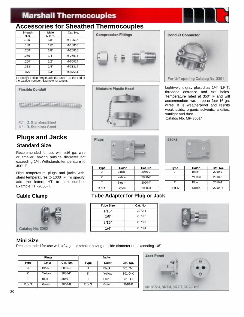
Accessories for Sheathed ThermocouplesSheath
O.D.Male
N.P.T.Cat. No.
.125" 1/8" M-12518
.188" 1/8" M-18818
.250" 1/8" M-25018
.250" 1/4" M-25014
.250" 1/2" M-50014
.313" 1/4" M-31314
.375" 1/4" M-37514
To specify Teflon ferrule, add the letter T to the end ofthe catalog number. Example: M-12518T.
Lightweight gray plastichas 1/4" N.P.T.threaded entrance and exit holes.Temperature rated at 350° F and willaccommodate two. three or four 16 ga.wires. It is weatherproof and resistsweak acids, organic solvents, alkalies,sunlight and dust.Catalog No. MP-35014
Type Color Cat. No.J Black 2010-J
K Yellow 2010-K
T Blue 2010-T
R or S Green 2010-R
Type Color Cat. No.J Black 2060-J
K Yellow 2060-K
T Blue 2060-T
R or S Green 2060-R
Plugs and JacksStandard SizeRecommended for use with #16 ga. wireor smaller, having outside diameter notexceeding 1/4". Withstands temperature to400° F.
High temperature plugs and jacks with-stand temperatures to 1000° F. To specify,add the letters HT to part number.Example: HT-2060-K.
Cable Clamp Tube Adapter for Plug or Jack
Tube Size Cat. No.
1/16" 2070-1
1/8" 2070-2
3/16" 2070-3
1/4" 2070-4
Mini SizeRecommended for use with #24 ga. or smaller having outside diameter not exceeding 1/8".
Jacks
Type Color Cat. No.
J Black 301 O-J
K Yellow 301 O-K
T Blue 301 O-T
R or S Green 3010-R
Plugs
Type Color Cat. No.
J Black 3060-J
K Yellow 3060-K
T Blue 3060-T
R or S Green 3060-R
20
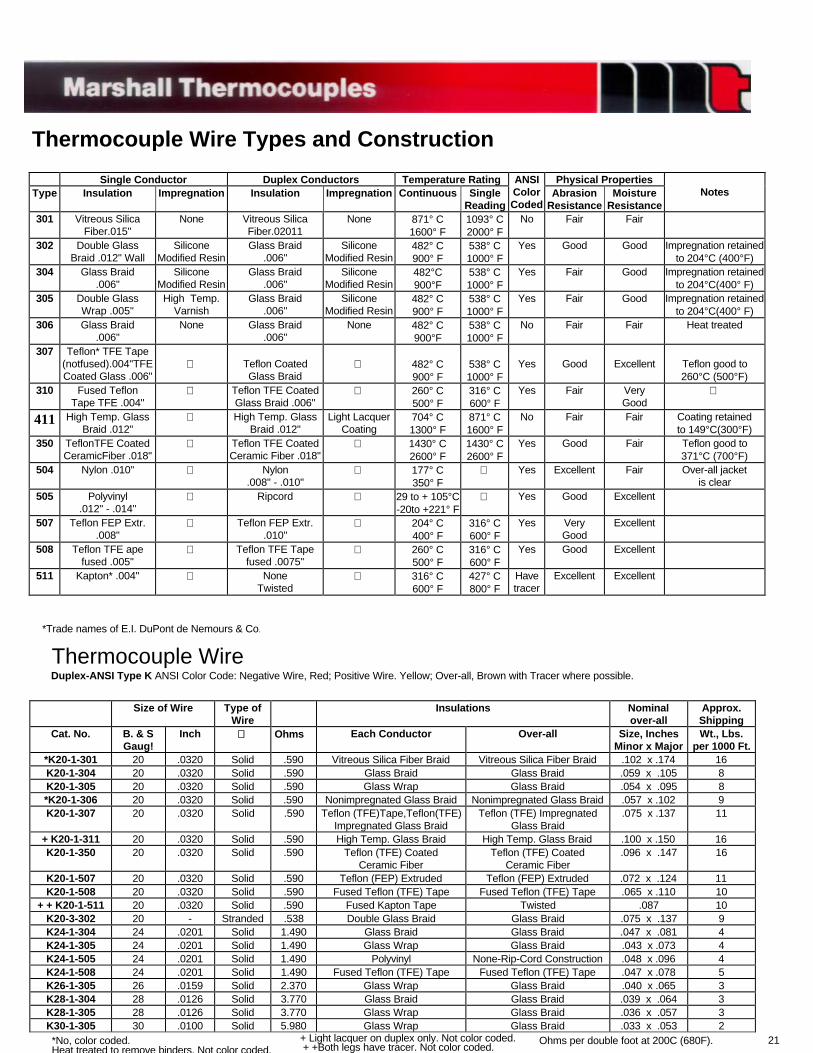
Thermocouple Wire Types and Construction
*Trade names of E.I. DuPont de Nemours & Co.
Thermocouple WireDuplex-ANSI Type K ANSI Color Code: Negative Wire, Red; Positive Wire. Yellow; Over-all, Brown with Tracer where possible.
21
Size of Wire Type ofWire
Insulations Nominalover-all
Approx.Shipping
Cat. No. B. & SGaug!
Inch Ohms Each Conductor Over-all Size, InchesMinor x Major
Wt., Lbs.per 1000 Ft.
*K20-1-301 20 .0320 Solid .590 Vitreous Silica Fiber Braid Vitreous Silica Fiber Braid .102 x .174 16K20-1-304 20 .0320 Solid .590 Glass Braid Glass Braid .059 x .105 8K20-1-305 20 .0320 Solid .590 Glass Wrap Glass Braid .054 x .095 8*K20-1-306 20 .0320 Solid .590 Nonimpregnated Glass Braid Nonimpregnated Glass Braid .057 x .102 9K20-1-307 20 .0320 Solid .590 Teflon (TFE)Tape,Teflon(TFE)
Impregnated Glass BraidTeflon (TFE) Impregnated
Glass Braid.075 x .137 11
+ K20-1-311 20 .0320 Solid .590 High Temp. Glass Braid High Temp. Glass Braid .100 x .150 16K20-1-350 20 .0320 Solid .590 Teflon (TFE) Coated
Ceramic FiberTeflon (TFE) Coated
Ceramic Fiber.096 x .147 16
K20-1-507 20 .0320 Solid .590 Teflon (FEP) Extruded Teflon (FEP) Extruded .072 x .124 11K20-1-508 20 .0320 Solid .590 Fused Teflon (TFE) Tape Fused Teflon (TFE) Tape .065 x .110 10
+ + K20-1-511 20 .0320 Solid .590 Fused Kapton Tape Twisted .087 10K20-3-302 20 - Stranded .538 Double Glass Braid Glass Braid .075 x .137 9K24-1-304 24 .0201 Solid 1.490 Glass Braid Glass Braid .047 x .081 4K24-1-305 24 .0201 Solid 1.490 Glass Wrap Glass Braid .043 x .073 4K24-1-505 24 .0201 Solid 1.490 Polyvinyl None-Rip-Cord Construction .048 x .096 4K24-1-508 24 .0201 Solid 1.490 Fused Teflon (TFE) Tape Fused Teflon (TFE) Tape .047 x .078 5K26-1-305 26 .0159 Solid 2.370 Glass Wrap Glass Braid .040 x .065 3K28-1-304 28 .0126 Solid 3.770 Glass Braid Glass Braid .039 x .064 3K28-1-305 28 .0126 Solid 3.770 Glass Wrap Glass Braid .036 x .057 3K30-1-305 30 .0100 Solid 5.980 Glass Wrap Glass Braid .033 x .053 2*No, color coded.Heat treated to remove binders. Not color coded.
+ Light lacquer on duplex only. Not color coded. + +Both legs have tracer. Not color coded.
Ohms per double foot at 200C (680F).
Single Conductor Duplex Conductors Temperature Rating Physical PropertiesType Insulation Impregnation Insulation Impregnation Continuous Single
Reading
ANSIColorCoded
AbrasionResistance
MoistureResistance
Notes
301 Vitreous SilicaFiber.015"
None Vitreous SilicaFiber.02011
None 871° C1600° F
1093° C2000° F
No Fair Fair
302 Double GlassBraid .012" Wall
SiliconeModified Resin
Glass Braid.006"
SiliconeModified Resin
482° C900° F
538° C1000° F
Yes Good Good Impregnation retainedto 204°C (400°F)
304 Glass Braid.006"
SiliconeModified Resin
Glass Braid.006"
SiliconeModified Resin
482°C900°F
538° C1000° F
Yes Fair Good Impregnation retainedto 204°C(400° F)
305 Double GlassWrap .005"
High Temp.Varnish
Glass Braid.006"
SiliconeModified Resin
482° C900° F
538° C1000° F
Yes Fair Good Impregnation retainedto 204°C(400° F)
306 Glass Braid.006"
None Glass Braid.006"
None 482° C900°F
538° C1000° F
No Fair Fair Heat treated
307 Teflon* TFE Tape(notfused).004"TFECoated Glass .006"
Teflon CoatedGlass Braid
482° C900° F
538° C1000° F
Yes Good Excellent Teflon good to260°C (500°F)
310 Fused TeflonTape TFE .004"
Teflon TFE CoatedGlass Braid .006"
260° C500° F
316° C600° F
Yes Fair VeryGood
411 High Temp. GlassBraid .012"
High Temp. GlassBraid .012"
Light LacquerCoating
704° C1300° F
871° C1600° F
No Fair Fair Coating retainedto 149°C(300°F)
350 TeflonTFE CoatedCeramicFiber .018"
Teflon TFE CoatedCeramic Fiber .018"
1430° C2600° F
1430° C2600° F
Yes Good Fair Teflon good to371°C (700°F)
504 Nylon .010" Nylon.008" - .010"
177° C350° F
Yes Excellent Fair Over-all jacketis clear
505 Polyvinyl.012" - .014"
Ripcord 29 to + 105°C-20to +221° F
Yes Good Excellent
507 Teflon FEP Extr..008"
Teflon FEP Extr..010"
204° C400° F
316° C600° F
Yes VeryGood
Excellent
508 Teflon TFE apefused .005"
Teflon TFE Tapefused .0075"
260° C500° F
316° C600° F
Yes Good Excellent
511 Kapton* .004" NoneTwisted
316° C600° F
427° C800° F
Havetracer
Excellent Excellent
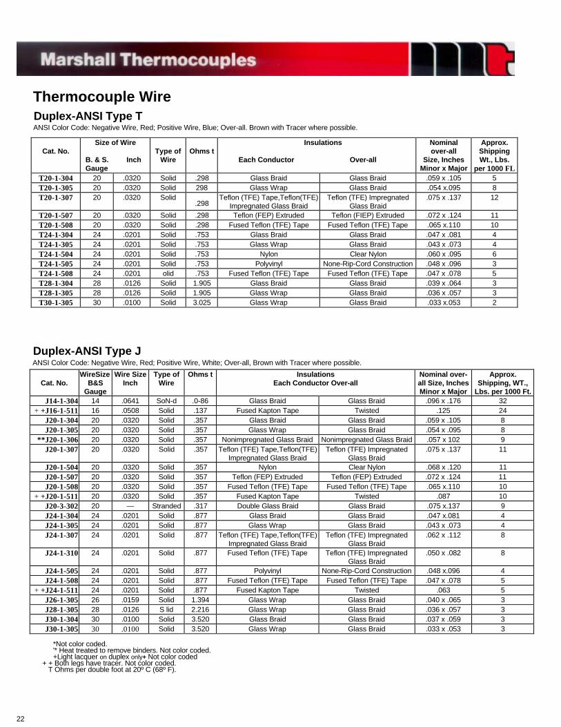
Thermocouple WireDuplex-ANSI Type TANSI Color Code: Negative Wire, Red; Positive Wire, Blue; Over-all. Brown with Tracer where possible.
Cat. No.Size of Wire
B. & S. Inch Gauge
Type ofWire
Ohms t Insulations
Each Conductor Over-all
Nominalover-all
Size, InchesMinor x Major
Approx.ShippingWt., Lbs.
per 1000 FLT20-1-304 20 .0320 Solid .298 Glass Braid Glass Braid .059 x .105 5T20-1-305 20 .0320 Solid 298 Glass Wrap Glass Braid .054 x.095 8T20-1-307 20 .0320 Solid
.298Teflon (TFE) Tape,Teflon(TFE)
Impregnated Glass BraidTeflon (TFE) Impregnated
Glass Braid.075 x .137 12
T20-1-507 20 .0320 Solid .298 Teflon (FEP) Extruded Teflon (FIEP) Extruded .072 x .124 11T20-1-508 20 .0320 Solid .298 Fused Teflon (TFE) Tape Fused Teflon (TFE) Tape .065 x.110 10T24-1-304 24 .0201 Solid .753 Glass Braid Glass Braid .047 x .081 4T24-1-305 24 .0201 Solid .753 Glass Wrap Glass Braid .043 x .073 4T24-1-504 24 .0201 Solid .753 Nylon Clear Nylon .060 x .095 6T24-1-505 24 .0201 Solid .753 Polyvinyl None-Rip-Cord Construction .048 x .096 3T24-1-508 24 .0201 olid .753 Fused Teflon (TFE) Tape Fused Teflon (TFE) Tape .047 x .078 5T28-1-304 28 .0126 Solid 1.905 Glass Braid Glass Braid .039 x .064 3T28-1-305 28 .0126 Solid 1.905 Glass Wrap Glass Braid .036 x .057 3T30-1-305 30 .0100 Solid 3.025 Glass Wrap Glass Braid .033 x.053 2
Duplex-ANSI Type JANSI Color Code: Negative Wire, Red; Positive Wire, White; Over-all, Brown with Tracer where possible.
Cat. No.WireSize
B&SGauge
Wire SizeInch
Type ofWire
Ohms t InsulationsEach Conductor Over-all
Nominal over-all Size, InchesMinor x Major
Approx.Shipping, WT.,
Lbs. per 1000 Ft.J14-1-304 14 .0641 SoN-d .0-86 Glass Braid Glass Braid .096 x .176 32
+ +J16-1-511 16 .0508 Solid .137 Fused Kapton Tape Twisted .125 24J20-1-304 20 .0320 Solid .357 Glass Braid Glass Braid .059 x .105 8J20-1-305 20 .0320 Solid .357 Glass Wrap Glass Braid .054 x .095 8
**J20-1-306 20 .0320 Solid .357 Nonimpregnated Glass Braid Nonimpregnated Glass Braid .057 x 102 9J20-1-307 20 .0320 Solid .357 Teflon (TFE) Tape,Teflon(TFE)
Impregnated Glass BraidTeflon (TFE) Impregnated
Glass Braid.075 x .137 11
J20-1-504 20 .0320 Solid .357 Nylon Clear Nylon .068 x .120 11J20-1-507 20 .0320 Solid .357 Teflon (FEP) Extruded Teflon (FEP) Extruded .072 x .124 11J20-1-508 20 .0320 Solid .357 Fused Teflon (TFE) Tape Fused Teflon (TFE) Tape .065 x.110 10
+ +J20-1-511 20 .0320 Solid .357 Fused Kapton Tape Twisted .087 10J20-3-302 20 — Stranded .317 Double Glass Braid Glass Braid .075 x.137 9J24-1-304 24 .0201 Solid .877 Glass Braid Glass Braid .047 x.081 4J24-1-305 24 .0201 Solid .877 Glass Wrap Glass Braid .043 x .073 4J24-1-307 24 .0201 Solid .877 Teflon (TFE) Tape,Teflon(TFE)
Impregnated Glass BraidTeflon (TFE) Impregnated
Glass Braid.062 x .112 8
J24-1-310 24 .0201 Solid .877 Fused Teflon (TFE) Tape Teflon (TFE) ImpregnatedGlass Braid
.050 x .082 8
J24-1-505 24 .0201 Solid .877 Polyvinyl None-Rip-Cord Construction .048 x.096 4J24-1-508 24 .0201 Solid .877 Fused Teflon (TFE) Tape Fused Teflon (TFE) Tape .047 x .078 5
+ +J24-1-511 24 .0201 Solid .877 Fused Kapton Tape Twisted .063 5J26-1-305 26 .0159 Solid 1.394 Glass Wrap Glass Braid .040 x .065 3J28-1-305 28 .0126 S lid 2.216 Glass Wrap Glass Braid .036 x .057 3J30-1-304 30 .0100 Solid 3.520 Glass Braid Glass Braid .037 x .059 3J30-1-305 30 .0100 Solid 3.520 Glass Wrap Glass Braid .033 x .053 3
*Not color coded.'* Heat treated to remove binders. Not color coded.+Light lacquer on duplex only+ Not color coded
+ + Both legs have tracer. Not color coded. T Ohms per double foot at 20º C (68º F).
22
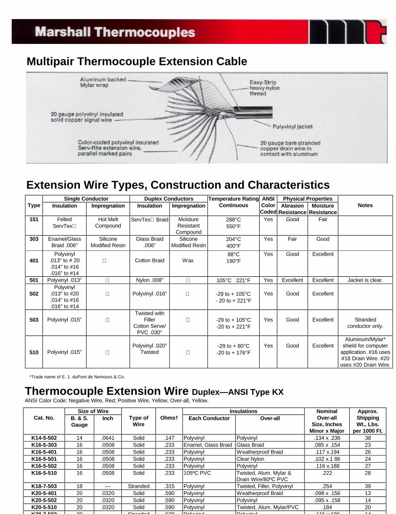
Multipair Thermocouple Extension Cable
Extension Wire Types, Construction and Characteristics
Thermocouple Extension Wire Duplex—ANSI Type KXANSI Color Code: Negative Wire, Red; Positive Wire, Yellow; Over-all, Yellow.
Size of Wire InsulationsCat. No. B. & S.
GaugeInch Type of
WireOhms† Each Conductor Over-all
NominalOver-all
Size, InchesMinor x Major
Approx.ShippingWt., Lbs.
per 1000 Ft.K14-5-502 14 .0641 Solid .147 Polyvinyl Polyvinyl .134 x .236 38K16-5-303 16 .0508 Solid .233 Enamel, Glass Braid Glass Braid .085 x .154 23K16-5-401 16 .0508 Solid .233 Polyvinyl Weatherproof Braid .117 x.194 26K16-5-501 16 .0508 Solid .233 Polyvinyl Clear Nylon .102 x.1 86 24K16-5-502 16 .0508 Solid .233 Polyvinyl Polyvinyl .116 x.188 27K16-5-510 16 .0508 Solid .233 105ºC PVC Twisted, Alum. Mylar &
Drain Wire/80ºC PVC.222 28
K18-7-503 18 — Stranded .315 Polyvinyl Twisted, Filler, Polyvinyl .254 39K20-5-401 20 .0320 Solid .590 Polyvinyl Weatherproof Braid .098 x .156 13K20-5-502 20 .0320 Solid .590 Polyvinyl Polyvinyl .095 x .158 14K20-5-510 20 .0320 Solid .590 Polyvinyl Twisted, Alum. Mylar/PVC .184 20K20 7 502 20 Stranded 538 Polyvinyl Polyvinyl 115 x 190 14
*Trade name of E. 1. duPont de Nemours & Co.
Single Conductor Duplex Conductors Physical PropertiesType Insulation Impregnation Insulation Impregnation
Temperature RatingContinuous
ANSIColorCoded
AbrasionResistance
MoistureResistance
Notes
151 FeltedServTex
Hot MeltCompound
ServTex Braid MoistureResistant
Compound
288°C550°F
Yes Good Fair
303 Enamel/GlassBraid .006"
SiliconeModified Resin
Glass Braid.006"
SiliconeModified Resin
204°C400°F
Yes Fair Good
401Polyvinyl
.013" to # 20.014" to #16.016" to #14
Cotton Braid Wax88°C190°F
Yes Good Excellent
501 Polyvinyl .013" Nylon .008" 105°C 221°F Yes Excellent Excellent Jacket is clear.
502Polyvinyl
.013" to #20
.014" to #16
.016" to #14
Polyvinyl .016" -29 to + 105°C- 20 to + 221°F
Yes Good Excellent
503 Polyvinyl .015" Twisted with
FillerCotton Serve/
PVC .030"
-29 to + 105°C-20 to + 221°F
Yes Good Excellent Strandedconductor only.
510 Polyvinyl .015" Polyvinyl .020"
Twisted -29 to + 80°C-20 to + 176°F
Yes Good ExcellentAluminum/Mylar*
shield for computerapplication. #16 uses#18 Drain Wire. #20uses #20 Drain Wire.
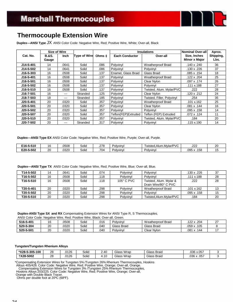
Thermocouple Extension WireDuplex—ANSI Type JX ANSI Color Code: Negative Wire, Red; Positive Wire, White; Over-all, Black
Size of Wire InsulationsCat. No. B.&S.
GaugeInch Type of Wire Ohms Each Conductor Over-all
Nominal Over-allSize, Inches
Minor x Major
Aprox.Shipping,
Lbs.
J14-5-401 14 .0641 Solid .086 Polyvinyl Weatherproof Braid .140 x .240 36J14-5-502 14 .0641 Solid .086 Polyvinyl Polyvinyl .130 x .226 37J16-5-303 16 .0508 Solid .137 Enamel, Glass Braid Glass Braid .085 x .154 18J16-5-401 16 .0508 Solid .137 Polyvinyl Weatherproof Braid .122 x .204 25J16-5-501 16 .0508 Solid .137 Polyvinyl Clear Nylon .097 x .174 26J16-5-502 16 .0508 Solid .137 Polyvinyl Polyvinyl .111 x.188 27J16-5-510 16 .0508 Solid .137 Polyvinyl Twisted, Alum. Mylar/PVC .222 28J16-7-501 16 — Stranded .125 Polyvinyl Clear Nylon .120 x .212 24J18-7-503 18 — Stranded .185 Polyvinyl Twisted, Filler, Polyvinyl .254 35J20-5-401 20 .0320 Solid .357 Polyvinyl Weatherproof Braid .101 x.162 25J20-5-501 20 .0320 Solid .357 Polyvinyl Clear Nylon .081 x .144 16J20-5-502 20 .0320 Solid .357 Polyvinyl Polyvinyl .095 x .158 14J20-5-507 20 .0320 Solid .357 Teflon(FEP)Extruded Teflon (FEP) Extruded .072 x .124 11J20-5-510 20 .0320 Solid .357 Polyvinyl Twisted, Alum. Mylar/PVC .184 20J20-7-502 20 — Stranded .317 Polyvinyl Polyvinyl .115 x.190 14
Duplex—ANSI Type EX ANSI Color Code: Negative Wire, Red; Positive Wire, Purple; Over-all, Purple.
E16-5-510 16 .0508 Solid .278 Polyvinyl Twisted,Alum.Mylar/PVC .222 20E20-5-502 20 .0320 Solid .704 Polyvinyl Polyvinyl .095 x .158 15
Duplex—ANSI Type TX ANSI Color Code: Negative Wire, Red; Positive Wire, Blue; Over-all, Blue.
T14-5-502 14 .0641 Solid .074 Polyvinyl Polyvinyl .130 x .226 37T16-5-502 16 .0508 Solid .118 Polyvinyl Polyvinyl .111 x.188 28T16-5-510 16 .0508 Solid .118 105° C PVC Twisted, Alum. Mylar &
Drain Wire/80° C PVC.222 28
T20-5-401 20 .0320 Solid .298 Polyvinyl Weatherproof Braid .101 x.162 13T20-5-502 20 .0320 Solid .298 Polyvinyl Polyvinyl .095 x .158 15T20-5-510 20 .0320 Solid .298 Polyvinyl Twisted,Alum.Mylar/PVC .184 20
Duplex-ANSI Type SX and RX Compensating Extension Wires for ANSI Type R, S Thermocouples.ANSI Color Code: Negative Wire, Red; Positive Wire, Black; Over-all, Green.S16-5-401 16 .0508 Solid .016 Polyvinyl Weatherproof Braid .122 x .204 27S20-5-304 20 .0320 Solid .040 Glass Braid Glass Braid .059 x .105 8S20-5-501 20 .0320 Solid .040 Polyvinyl Clear Nylon .081 x .144 17
Tungsten/Tungsten Rhenium Alloys
*X28-5-305-100 28 .0126 Solid 2.40 Glass Wrap Glass Braid .036 x.057 3†X28-5002 28 .0126 Solid 4.10 Glass Wrap Glass Braid .036 x .057 3
*Compensating Extension Wires for Tungsten 5% /Tungsten 26% Rhenium Thermocouples, HoskinsAlloys 405/426. Color Code: Negative Wire, Red; Positive Wire, Orange; Over-all, Orange.
Compensating Extension Wires for Tungsten 3% /Tungsten 25% Rhenium Thermocouples,Hoskins Alloys 203/225. Color Code: Negative Wire, Red; Positive Wire, Orange; Over-all,
Orange with Double Black Tracer.Ohms per double foot at 20ºC (68ºF).
24
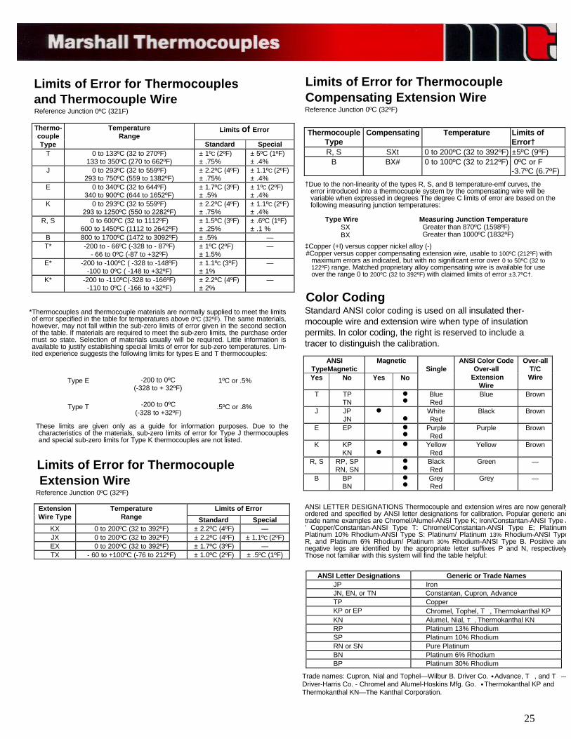
Limits of Error for Thermocouplesand Thermocouple WireReference Junction 0ºC (321F)
Limits of Error for ThermocoupleCompensating Extension WireReference Junction 0ºC (32ºF)
Limits of ErrorThermo-coupleType
TemperatureRange
Standard SpecialT 0 to 133ºC (32 to 270ºF)
133 to 350ºC (270 to 662ºF) ± 1ºC (2ºF) ± .75%
± 5ºC (1ºF) ± .4%
J 0 to 293ºC (32 to 559ºF)293 to 750ºC (559 to 1382ºF)
± 2.2ºC (4ºF) ± .75%
± 1.1ºC (2ºF) ± .4%
E 0 to 340ºC (32 to 644ºF)340 to 900ºC (644 to 1652ºF)
± 1.7ºC (3ºF) ± .5%
± 1ºC (2ºF) ± .4%
K 0 to 293ºC (32 to 559ºF)293 to 1250ºC (550 to 2282ºF)
± 2.2ºC (4ºF) ± .75%
± 1.1ºC (2ºF) ± .4%
R, S 0 to 600ºC (32 to 1112ºF)600 to 1450ºC (1112 to 2642ºF)
± 1.5ºC (3ºF) ± .25%
± .6ºC (1ºF) ± .1 %
B 800 to 1700ºC (1472 to 3092ºF) ± .5% —T* -200 to - 66ºC (-328 to - 87ºF)
- 66 to 0ºC (-87 to +32ºF) ± 1ºC (2ºF) ± 1.5%
—
E* -200 to -100ºC ( -328 to -148ºF)-100 to 0ºC ( -148 to +32ºF)
± 1.1ºC (3ºF) ± 1%
—
K* -200 to -110ºC(-328 to -166ºF)-110 to 0ºC ( -166 to +32ºF)
± 2.2ºC (4ºF) ± 2%
—
*Thermocouples and thermocouple materials are normally supplied to meet the limitsof error specified in the table for temperatures above 0ºC (32ºF). The same materials,however, may not fall within the sub-zero limits of error given in the second sectionof the table. If materials are required to meet the sub-zero limits, the purchase ordermust so state. Selection of materials usually will be required. Little information isavailable to justify establishing special limits of error for sub-zero temperatures. Lim-ited experience suggests the following limits for types E and T thermocouples:
Type E
Type T
-200 to 0ºC(-328 to + 32ºF)
-200 to 0ºC(-328 to +32ºF)
1ºC or .5%
.5ºC or .8%
These limits are given only as a guide for information purposes. Due to thecharacteristics of the materials, sub-zero limits of error for Type J thermocouplesand special sub-zero limits for Type K thermocouples are not listed.
Limits of Error for ThermocoupleExtension Wire
Reference Junction 0ºC (32ºF)
Limits of ErrorExtensionWire Type
TemperatureRange Standard Special
KX 0 to 200ºC (32 to 392ºF) ± 2.2ºC (4ºF) —JX 0 to 200ºC (32 to 392ºF) ± 2.2ºC (4ºF) ± 1.1ºC (2ºF)EX 0 to 200ºC (32 to 392ºF) ± 1.7ºC (3ºF) —TX - 60 to +100ºC (-76 to 212ºF) ± 1.0ºC (2ºF) ± .5ºC (1ºF)
25
Trade names: Cupron, Nial and Tophel—Wilbur B. Driver Co. ·Advance, T , and T —Driver-Harris Co. - Chromel and Alumel-Hoskins Mfg. Go. ·Thermokanthal KP andThermokanthal KN—The Kanthal Corporation.
ANSI Letter Designations Generic or Trade Names JP Iron JN, EN, or TN Constantan, Cupron, Advance TP Copper KP or EP Chromel, Tophel, T , Thermokanthal KP KN Alumel, Nial, T , Thermokanthal KN RP Platinum 13% Rhodium SP Platinum 10% Rhodium RN or SN Pure Platinum BN Platinum 6% Rhodium BP Platinum 30% Rhodium
ANSI LETTER DESIGNATIONS Thermocouple and extension wires are now generallyordered and specified by ANSI letter designations for calibration. Popular generic andtrade name examples are Chromel/Alumel-ANSI Type K; Iron/Constantan-ANSI Type J' Copper/Constantan-ANSI Type T: Chromel/Constantan-ANSI Type E; PlatinumPlatinum 10% Rhodium-ANSI Type S: Platinum/ Platinum 13% Rhodium-ANSI TypeR, and Platinum 6% Rhodium/ Platinum 30% Rhodium-ANSI Type B. Positive andnegative legs are identified by the appropriate letter suffixes P and N, respectivelyThose not familiar with this system will find the table helpful:
ANSITypeMagnetic
Magnetic
Yes No Yes NoSingle
ANSI Color CodeOver-all
ExtensionWire
Over-allT/CWire
T TPTN
nn
BlueRed
Blue Brown
J JPJN
n
n
WhiteRed
Black Brown
E EP nn
PurpleRed
Purple Brown
K KPKN n
n YellowRed
Yellow Brown
R, S RP, SPRN, SN
nn
BlackRed
Green —
B BPBN
nn
GreyRed
Grey —
Color CodingStandard ANSI color coding is used on all insulated ther-mocouple wire and extension wire when type of insulationpermits. In color coding, the right is reserved to include atracer to distinguish the calibration.
‡Copper (+I) versus copper nickel alloy (-)#Copper versus copper compensating extension wire, usable to 100ºC (212ºF) with
maximum errors as indicated, but with no significant error over 0 to 50ºC (32 to122ºF) range. Matched proprietary alloy compensating wire is available for useover the range 0 to 200ºC (32 to 392ºF) with claimed limits of error ±3.7ºC†.
Type WireSXBX
Measuring Junction TemperatureGreater than 870ºC (1598ºF)Greater than 1000ºC (1832ºF)
†Due to the non-linearity of the types R, S, and B temperature-emf curves, theerror introduced into a thermocouple system by the compensating wire will bevariable when expressed in degrees The degree C limits of error are based on thefollowing measuring junction temperatures:
ThermocoupleType
Compensating Temperature Limits ofError†
R, S SXt 0 to 200ºC (32 to 392ºF) ±5ºC (9ºF)B BX# 0 to 100ºC (32 to 212ºF) 0ºC or F
-3.7ºC (6.7ºF)
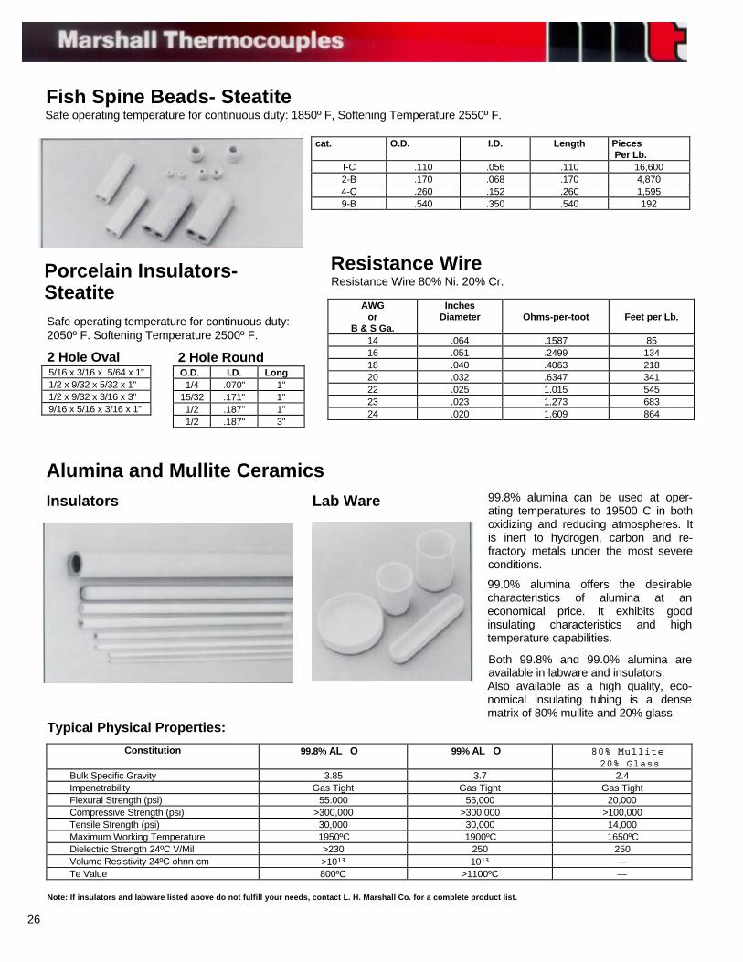
Fish Spine Beads- SteatiteSafe operating temperature for continuous duty: 1850º F, Softening Temperature 2550º F.
cat. O.D. I.D. Length Pieces Per Lb.
I-C .110 .056 .110 16,6002-B .170 .068 .170 4,8704-C .260 .152 .260 1,5959-B .540 .350 .540 192
Resistance WireResistance Wire 80% Ni. 20% Cr.
Porcelain Insulators-SteatiteSafe operating temperature for continuous duty:2050º F. Softening Temperature 2500º F.
5/16 x 3/16 x 5/64 x 1"1/2 x 9/32 x 5/32 x 1"1/2 x 9/32 x 3/16 x 3"9/16 x 5/16 x 3/16 x 1"
2 Hole OvalO.D. I.D. Long
1/4 .070" 1"15/32 .171" 1"1/2 .187" 1"1/2 .187" 3"
2 Hole Round
AWGor
B & S Ga.
InchesDiameter Ohms-per-toot Feet per Lb.
14 .064 .1587 8516 .051 .2499 13418 .040 .4063 21820 .032 .6347 34122 .025 1.015 54523 .023 1.273 68324 .020 1.609 864
Alumina and Mullite CeramicsInsulators Lab Ware 99.8% alumina can be used at oper-
ating temperatures to 19500 C in bothoxidizing and reducing atmospheres. Itis inert to hydrogen, carbon and re-fractory metals under the most severeconditions.
99.0% alumina offers the desirablecharacteristics of alumina at aneconomical price. It exhibits goodinsulating characteristics and hightemperature capabilities.
Both 99.8% and 99.0% alumina areavailable in labware and insulators.Also available as a high quality, eco-nomical insulating tubing is a densematrix of 80% mullite and 20% glass.
Typical Physical Properties:
Constitution 99.8% AL O 99% AL O 80% Mullite80% Mullite 20% Glass 20% Glass
Bulk Specific Gravity 3.85 3.7 2.4 Impenetrability Gas Tight Gas Tight Gas Tight Flexural Strength (psi) 55.000 55,000 20,000 Compressive Strength (psi) >300,000 >300,000 >100,000 Tensile Strength (psi) 30,000 30,000 14,000 Maximum Working Temperature 1950ºC 1900ºC 1650ºC Dielectric Strength 24ºC V/Mil >230 250 250 Volume Resistivity 24ºC ohnn-cm >10¹³ 10¹³ — Te Value 800ºC >1100ºC —
Note: If insulators and labware listed above do not fulfill your needs, contact L. H. Marshall Co. for a complete product list.
26
27