english electric high voltage hrc fuse links
TRANSCRIPT

H.R.C.FUSE-LINKS
11 kV 5-100 750
AMP MVA

ENGLISH ELECTRIC'
HIGH VOLTAGE H.R.C. FUSE-LINKS
(PATENTS PENDING)
TO B.S. 2692:1956
Intensive research and testing, based on more than thirty-five years of experience
as the World’s leading manufacturer of medium voltage H.R.C. fuse-links,
have enabled ‘English Electric’ to introduce High Voltage fuse-links possessing
equally high standards of design, quality and performance.
Strict quality control throughout manufacture guarantees these high standards
and ensures complete uniformity of product.
This publication gives details of the ranges available and each rating of fuse-
link is listed together with ordering references, dimensions and characteristic
curves.

CONTENTS PAGE
APPLICATION 3
QUALITY CONTROL 4 and
LIST NUMBERS and DIMENSIONS
3-3 kV H.R.C. FUSE-LINKS 6 and
11 kV H.R.C. FUSE-LINKS 8 and
INDOOR FUSE MOUNTS 10
CHARACTERISTIC CURVES (INDEX) and DERIVATION OF LIST NUMBERS 11
APPLICATION There are two complete ranges of Type ‘K’ fuse-links available for service up to and including 11 kV, both of which are fully tested and ASTA certified to B.S.2692:1956:—
3*3 kV 150 MVA with current ratings 5 to 200 amp 11 kV 250 MVA with current ratings 5 to 100 amp
ASTA certificates of rating are issued only in respect of British Standard ratings and the above short-circuit ratings correspond to the highest categories specified in B.S.2692:1956. Additional tests, in accordance with the provisions of B.S.2692, have been carried out successfully to prove the 3*3 kV fuse-link to 250 MVA and the 11 kV fuse-link to 750 MVA.
Arc voltages produced during operation are appreciably below the values given in B.S.2692 on rated voltages,and also on 2*2 kVin the case of 3*3kVfuse-links and on 6*6 kV for 11 kVfuse-links.
The 3*3 kV fuse-links are suitable for use in air, with or without striker pin operation, and are provided with off-set tags for bolted connections.
The 11 kV fuse-links are suitable for use in air, with or without striker pin operation, and fitted with ferrule type contacts or off-set tags. A limited range for use in oil, primarily intended for replacement purposes, is also available.
Variations to type and size of tag assemblies can be arranged to suit special requirements, and indoor fuse mounts are available (see dimensional drawings on page 10). Motor starting is particularly catered for, with time/current characteristics designed to give a high current with¬ stand during the starting period.
These fuse-links will operate successfully in parallel, enabling circuits requiring fuses in excess of 200 amp at 3*3 kV and in excess of 100 amp at 11 kV to be catered for. Details on application.

QUALITY CONTROL Every user will appreciate, that by its very nature of duty, protective equipment must incorporate the highest degree of quality to ensure long life to expensive apparatus and minimise shut-down of plant. This responsibility to industry has always been paramount in ‘English Electric’ throughout their unrivalled experience in H.R.C. fuse manufacture, and is evident in the manu¬ facturing control on High Voltage fuses, and also in the choice of designs selected to ensure the coolest running under normal load conditions.
Individual elements are fabricated from pure silver and are carefully examined during manu¬ facture of the fuse-links. All the 11 kV elements, and the higher ratings in the 3*3 kV range, are supported on star cores, or formers, and located at each end. The overall electrical resistance is checked by means of an ohmic test and each element assembly is inserted into a ceramic body which is then filled with pure granulated quartz. Silver plated copper ferrules are sealed to each end of the fuse body.
Due to the more intricate construction of the 11 kV fuse-links additional safety measures are taken as upon completion, each is carefully examined by radiograph. The radiograph is marked with the relevant serial number of the fuse and these records are available for inspection at any time.
Fig.l A typical radiograph of an 11 kV fuse-link.
Fig. 2 Completed 11 kV fuse-links being given a routine check for correct resistance.
After radiographing, each fuse-link is again tested for correct ohmic resistance, and in addition to the above, all fuses for use in oil are subjected to a searching hot water test to prove the
efficiency of the oil seal. This is a routine test for each fuse, and is additional to the normal type tests laid down
__ in B.S.2692:1956.
Considerable care is taken in the packing and storage of the fuse-links as, on com¬ pletion of manufacture, each fuse-link is sealed in a transparent P.V.C. envelope to give protection to current-carrying parts whilst in storage and further protection is given by enclosure in a strong outer carton.

Fig, 3 General view of one of the control rooms at the Nelson High Power Laboratory, Stafford, where short-circuit testing of High Voltage fuse-links is carried out.
Fig. 4 General view of part of Fusegear Division Test Laboratory at Liverpool, taken while tests on High Voltage fuse-links were in progress.

3*3 kV HIGH VOLTAGE H.R.C.
LIST NUMBERS for ordering purposes
TAG CONTACTS
TYPES K3PB & K3PBX
TYPES K4PC & K4PCX
Rating Amp
List No.
With Striker
Without Striker
5 K3PBX5A K2PA5A
10 K3PBX10A K2PA10A
15 K3PBX15A K2PA15A
20 K3PBX20A K2PA20A
25 K3PBX25A K2PA25A
30 K3PBX30A K2PA30A
40 K3PBX40A K2PA40A
50 K3PBX50A K2PA50A
60 K3PBX60A K3PB60A
75 K3PBX75A K3PB75A
100 K3PBX100A K3PB100A
150 K4PCX150A K4PC150A
200 K4PCX200A K4PC200A

FOR USE IN AIR FUSE-LINKS -
DIMENSIONS IN INCHES
List No. Prefix Rating Amp A B D E G H J K L M N p
K2PA (without striker)
5,10,15,20 25, 30, 40, 50 7i
(±i*s) m u 9i
(±T6) i 8 i —
K3PBX (with striker)
5,10.15. 20. 25. 30. 40. 50. 60. 75.100
7i
(±tV) 2* 2 '•A n lOi
(±tV) i I n i 1
max. K3PB
(without striker) 60, 75, 100
K4PCX (with striker)
K4PC (without striker)
150, 200 7i
(±tV) H 3* lOi
(±tV) i i i| i 1
max.
7

11 kV HIGH VOLTAGE H.R.G.
TYPES KEB & KEBX
(TYPES KEBO i KEBXO FOR USE IN OIL)
LIST NUMBERS for ordering purposes
FERRULE CONTACTS
For use in AIR For use in AIR For use in OIL
TYPES KEA & KEA)
LONG '
Rating Amp
List No.
With Without Striker Striker
5 KEAX5A KEA5A 10 KEAX10A KEA10A 15 KEAX15A KEA15A 1 20 KEAX20A KEA20A 1 25 KEAX25A KEA25A n 30 KEAX30A KEA30A 40 KEAX40A KEA40A 50 KEAX50A KEA50A 60 KEAX60A KEA60A 75 KEAX75A KEA75A
100 KEAX100A KEA100A
TYPES K6EB & K6EBX
TYPES K5EA & K5EAX
1 10" LONG 10" LONG
Rating List No.
Rating List No.
Amp With Without Amp With Without Striker Striker Striker Striker
5 KEBX5A KEB5A 5 KEBX05A KEB05A
10 KEBX10A KEB10A 10 KEBXO10A KEBO10A
15 KEBX15A KEB15A 15 KEBX015A KEB015A
20 KEBX20A KEB20A 20 KEBXO20A KEBO20A 25 KEBX025A KEB025A
25 KEBX25A KEB25A 30 KEBXO30A KEBO30A 30 KEBX30A KEB30A 40 KEBXO40A KEBO40A 40 KEBX40A KEB40A 50 KEBXO50A KEBO50A 50 KEBX50A KEB50A 60 KEBXO60A KEBO60A
TAG CONTACTS For use in AIR For use in AIR 16i:" FIXING CENTRES
Rating Amp
List No.
With Without Striker Striker
5 K5EAX5A K5EA5A 10 K5EAX10A K5EA10A 15 K5EAX15A K5EA15A 20 K5EAX20A K5EA20A 25 K5EAX25A K5EA25A 30 K5EAX30A K5EA30A 40 K5EAX40A K5EA40A 50 K5EAX50A K5EA50A 60 K5EAX60A K5EA60A 75 K5EAX75A K5EA75A
100 K5EAX100A K5EA100A
12i r" FIXING CENTRES
Rating Amp
List No.
With Without Striker Striker
5 K6EBX5A K6EB5A 10 K6EBX10A K6EB10A 15 K6EBX15A K6EB15A 20 K6EBX20A K6EB20A 25 K6EBX25A K6EB25A 30 K6EBX30A K6EB30A 40 K6EBX40A K6EB40A 50 K6EBX50A K6EB50A
8

FUSE-LINKS FOR USE IN AIR / EXCEPT TYPES KEBO & KEBXO \^WHICH ARE SUITABLE FOR USE IN OIL )
DIMENSIONS IN INCHES
—1-
- A-
P
FERRULE
Ir.
CONTACTS
t c
* B
♦ D
A
1 s 1 <
— pi- \ ^
STRIKER, IF FITTED.
List No. Prefix Rating Amp A B c D E F p
KEAX (with striker)
KEA (without striker)
5, 10. 15. 20
25. 30. 40. 50 60. 75.100
14i
(±iV) 3 H 2i '•A i
max.
KEBX (with striker) KEB (without striker)
5.10.15. 20 25. 30. 40. 50
10
(iiV) 2i H ‘•A i
max.
For use in oil: KEBXO (with striker) KEBO (without striker)
5.10.15 20. 25. 30 40. 50. 60
10
{±tV) 2i 2i 2i 1} 1tV i
max.
-j-
l—_ A
“T- K K
Ph
■ i
B I-
D
1.
1
I ^ .-Vi -r . I 1
3~ - • V7
L
-H-
\ STRIKER. 1
TAG CONTACTS
Crs.
List No. Prefix Rating Amp A B C D E F G H J K L M N P
K5EAX (with striker) K5EA (without striker)
5. 10. 15. 20 25. 30. 40. 50
60. 75. 100
14i
(±iV) 3 H 2i Ui 17|
(±lV) ■fi 1-H i f
max.
K6EBX (with striker) K6EB (without striker)
5.10.15.20 25. 30. 40. 50
10
(±it)
2i 2| 2| 1tV 2i 12i 13|
{±iV) If IT i 1
max.

INDOOR FUSE MOUNTS
DIMENSIONS IN INCHES
VOLTAGE FUSE MOUNT
ORDERING REF. FOR USE WITH
FUSE-LINKS TYPE A B C D E F G H
3-3 kV P76313-30
K2PA n 13i 1-fi ^^ 5|i m 3i 2*
K3PB. K3PBX H 13i 1H 15i ^•h 2* 3i 2i
K4PC, K4PCX 9i 13i m 15i i-h 3i 3* 2*
11 kV
P76313-20 K5EA, K5EAX 16i lOi m 22i 10* 3* SH 2*
P76313-10 K6EB, K6EBX 12i 16i m 18* 9+i 2f SH 2*

CHARACTERISTIC CURVES INDEX OF CHARACTERISTIC CURVES SHOWN ON PAGES 12-19 For further information please refer to ‘English Electric’, Fusegear Division, Liverpool.
3-3 kV H.R.C. FUSE-LINKS P*GE
Time/Prospective Current 12 Cut-off Current/Prospective Current 13 Maximum Values of Pt 13
11 kV H.R.C. FUSE-LINKS (wr body) Time/Prospective Current 14 Cut-off Current/Prospective Current 15 Maximum Values of Pt 15
11 kV H.R.C. FUSE-LINKS (io- body) Time/Prospective Current 16
Cut-off Current/Prospective Current 17
Maximum Values of Pt 17
11 kV H.R.C. FUSE-LINKS (io bodv-for use in did
Time/Prospective Current 18 Cut-off Current/Prospective Current 19 Maximum Values of Pt 19
DERIVATION OF LIST NUMBERS FIRST LETTER: This is always ‘K’ and denotes the type reference for high voltage H.R.C. fuse-links listed in this publication.
SECOND LETTER: Denotes voltage rating: ‘P’ = 3-3 kV, ‘E’ = 11 kV.
SECOND & THIRD IN COMBINATION: Denotes dimensions of fuse body and manufacturing specification.
FOURTH LETTER (When used): Can be ‘X’ or ‘O’. ‘X’=Striker pin fitted; ‘O’=For use in Oil.
FIFTH LETTER (When used): Will always be ‘O’ and denotes for use in Oil.
FINAL LETTER: This is always ‘A’ and denotes ‘Amperes’.
NUMBERS (a) If a number appears immediately after the prefix letter ‘K’ the fuse-link is fitted with tag contacts to a design
represented by the number. Otherwise ferrule contacts are fitted.
(b) The number immediately preceding the final letter ‘A’ denotes the current rating of the fuse-link in amperes.
EXAMPLES K5EAX100A Denotes a tag contact (5) fuse-link of 11 kV rating (E) with body dimensions (EA), fitted with striker pin (X) and
of lOOA rating.
KEBO60A Denotes a ferrule contact fuse-link of 11 kV rating (E) with body dimensions (EB) for use in oil (O) and of 60A rating.
11

TIM
E/CU
RREN
T CH
ARAC
TERI
STIC
S -3
*3 K
V TY
PES
K2P
A,
K3P
B,
K3P
BX,
K4P
C,
K4P
CX •
FOR
USE
IN A
IR
<
X d d
S3>l3dWV Nl lN3U>inD 3AllD3dSO>Jd 1VDIdl3NNAS SW^I
12
PR
E-A
RC
ING
TIM
E

CUT-
OFF
CURR
ENT
CHAR
ACTE
RIST
ICS
PR
OS
PE
CT
IVE
CU
RR
EN
T
kA
(SY
MM
ET
RIC
AL
R.M
.S.)

TIM
E/CU
RREN
T CH
ARA
CTER
ISTI
CS
• 11 K
V TY
PES
KEA. K
EAX.
K5E
A.
K5E
AX
• FO
R US
E IN A
IR
OQ
X
d d
S3y3dWV Nl lN3UUnD 3AllD3dSOyd 1VDIdl3WWAS S'W'd
14
PR
E-A
RC
ING
TIM
E

CUT-
OFF
CURR
ENT
CHAR
ACTE
RIST
ICS

TIM
E/CU
RREN
T CH
ARA
CTER
ISTI
CS
• 11 K
V TY
PES
KEB
, K
EBX
, K
6EB, K
6EBX
• FO
R U
SE I
N A
IR
S3>l3dWV Nl lN3WynD 3AllD3dSO>ld nVDIdJ.3WWAS SWd
16
PR
E-A
RC
ING
TIM
E

CUT-
OFF
CURR
ENT
CHAR
ACTE
RIST
ICS
(SNOIliaNOD iinvd 1VDI«X3WWASV) V>l lN3»ynD ddO-inD 17

TIM
E/CU
RREN
T CH
ARA
CTER
ISTI
CS
' 11 K
V TY
PES
KEBO
. KE
BXO
• FO
R US
E IN O
IL
CM
X Q d
2 D z
Q Z o u
b
S3U3dWV Nl lN3UdnD 3AllD3dSOdd 1VDIdl3WWAS 'SW>I
18
PR
E-A
RC
ING
TIM
E
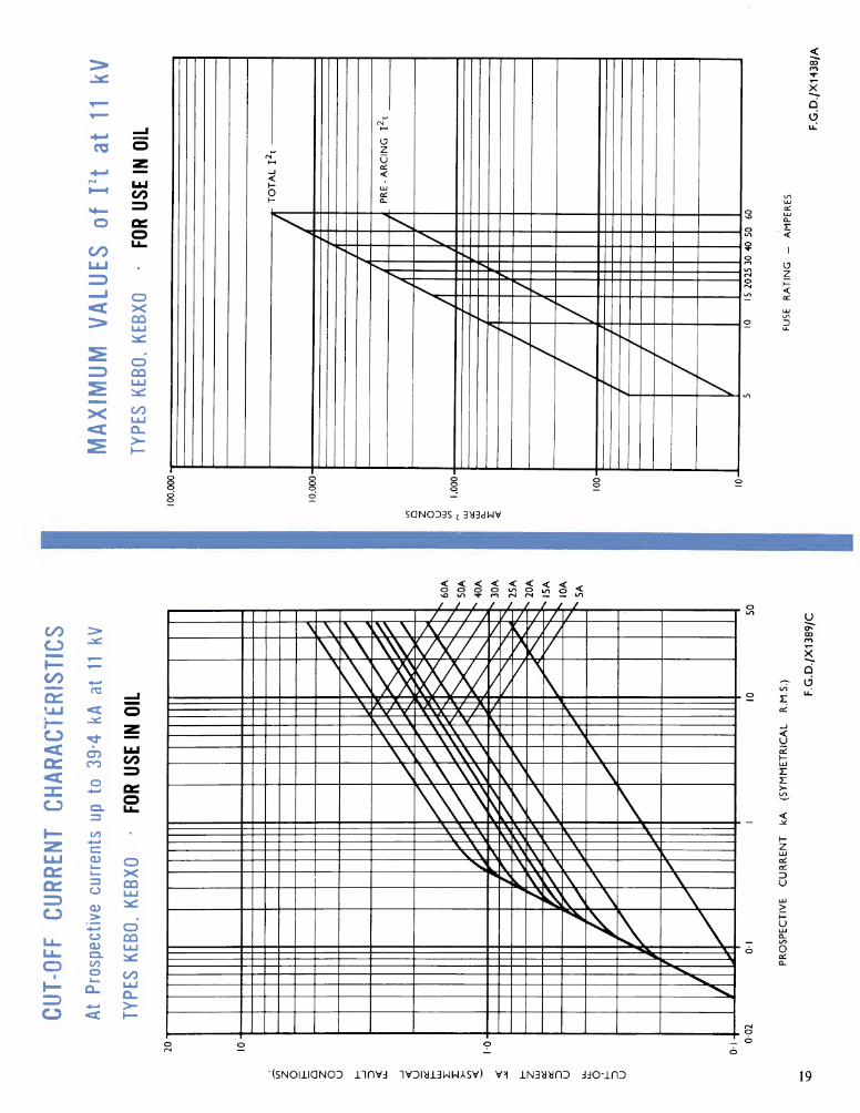
(SNOIliaNOD iinvd 1VDI»i3WWASV) V>l iN3y»nD ddO-iOD 19
NOTE: The Company's policy is one of continuous development
and improvement of its products, and therefore, the right is reserved
to supply products which may differ slightly from those illustrated
and described in this publication.
Publication FG/204A 1265150JC/RPU