ag 2007 beta protecting low-voltage fuse systems · beta protecting low-voltage fuse systems lv hrc...
TRANSCRIPT

BETA ProtectingLow-Voltage Fuse Systems
LV HRC fuse links
3/36 Siemens ET B1 · 2008
3
* You can order this quantity or a multiple thereof.
■ Overview
LV HRC fuses are used for installation systems in non-residential, commercial and industrial buildings as well as in switchboards of power supply companies. They therefore protect essential building parts and installations.
LV HRC fuses are fuse systems designed for operation by scilled personnel. There are no constructional requirements for non-inter-changeability of rated current and touch protection.
The components and auxiliary equipment are designed in such a way as to ensure the safe replacement of LV HRC fuses or isolation of systems.
LV HRC fuse links are available in the sizes 000, 00, 0, 1, 2, 3, 4 and 4a.
LV HRC fuse links are available in the following operational classes:• gG for cable and line protection• aM for the short-circuit protection of switching devices in motor circuits • gR or aR for the protection of power semiconductors • gS: The new gS operational class combines cable and line protection
with semiconductor protection.
LV HRC fuse links of size 000 can also be used in LV HRC fuse bases, LV HRC fuse switch disconnectors, LV HRC fuse strips as well as in LV HRC in-line fuse switch disconnectors of size 00.
The fuse links 300 A, 355 A and 425 A comply with the standard but do not have the VDE mark.
LV HRC components$ LV HRC fuse base from the SR60 busbar system% LV HRC fuse base for busbar mounting& LV HRC fuse base, 3P( LV HRC fuse base, 1P) LV HRC contact covers* LV HRC fuse link+ LV HRC signal detectors, LV HRC partition- LV HRC protective cover
LV HRC fuse bases with slewing equipment,. - for screw fixing on mounting plate/ - for screw fixing on busbar system 0 - for claw fixing on busbar/1LV HRC protective cover for LV HRC fuse bases with slewing
equipment
2 LV HRC slewing equipment3 LV HRC fuse base cover4 LV HRC isolating link with insulated grip lugs5 LV HRC isolating link with non-insulated grip lugs6 LV HRC fuse puller with sleeve7 LV HRC fuse puller
I2_13743
1
23
45
6
15 16 17 18 19
10 11 12
14
13
9
8
7
© Siemens AG 2007
BETA ProtectingLow-Voltage Fuse Systems
LV HRC fuse links
3/37Siemens ET B1 · 2008
12
34567891011121314151617* You can order this quantity or a multiple thereof.
■ Benefits
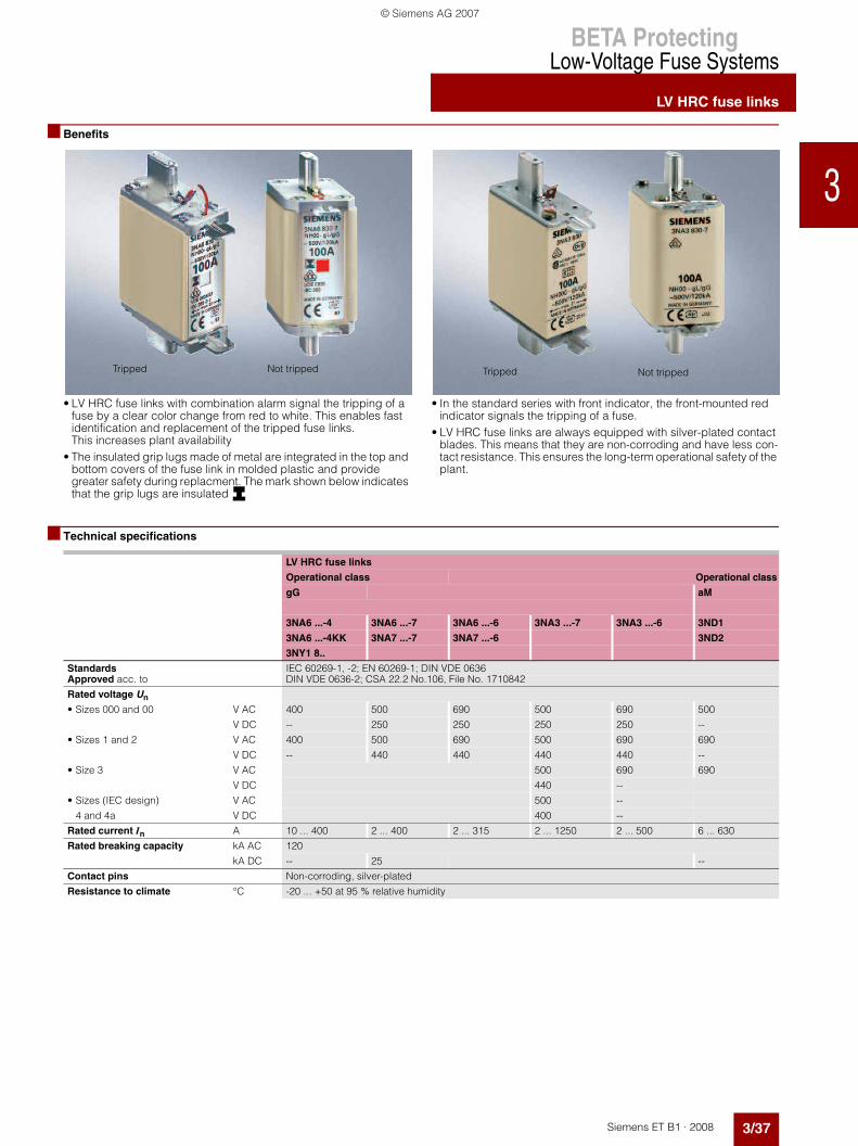
• LV HRC fuse links with combination alarm signal the tripping of a fuse by a clear color change from red to white. This enables fast identification and replacement of the tripped fuse links. This increases plant availability
• The insulated grip lugs made of metal are integrated in the top and bottom covers of the fuse link in molded plastic and provide greater safety during replacment. The mark shown below indicates that the grip lugs are insulated
• In the standard series with front indicator, the front-mounted red indicator signals the tripping of a fuse.
• LV HRC fuse links are always equipped with silver-plated contact blades. This means that they are non-corroding and have less con-tact resistance. This ensures the long-term operational safety of the plant.
■ Technical specifications
Tripped Not tripped Tripped Not tripped
LV HRC fuse links
Operational class Operational class
gG aM
3NA6 ...-4 3NA6 ...-7 3NA6 ...-6 3NA3 ...-7 3NA3 ...-6 3ND1
3NA6 ...-4KK 3NA7 ...-7 3NA7 ...-6 3ND2
3NY1 8..
Standards IEC 60269-1, -2; EN 60269-1; DIN VDE 0636Approved acc. to DIN VDE 0636-2; CSA 22.2 No.106, File No. 1710842
Rated voltage Un
• Sizes 000 and 00 V AC 400 500 690 500 690 500
V DC -- 250 250 250 250 --
• Sizes 1 and 2 V AC 400 500 690 500 690 690
V DC -- 440 440 440 440 --
• Size 3 V AC 500 690 690
V DC 440 --
• Sizes (IEC design) V AC 500 --
4 and 4a V DC 400 --
Rated current In A 10 ... 400 2 ... 400 2 ... 315 2 ... 1250 2 ... 500 6 ... 630
Rated breaking capacity kA AC 120
kA DC -- 25 --
Contact pins Non-corroding, silver-plated
Resistance to climate °C -20 ... +50 at 95 % relative humidity
© Siemens AG 2007

BETA ProtectingLow-Voltage Fuse Systems
LV HRC fuse links
3/38 Siemens ET B1 · 2008
12
3456789101112131415
1716
* You can order this quantity or a multiple thereof.
■ Selection and ordering data
Insulated grip lugs
Sizes Mounting width In Un DT Order No. Priceper PU
PG PU PS*/P. unit
Weightper P. unitapprox
mm A V AC/V DC
Unit(s) Unit(s) kg
LV HRC fuse links with combination alarm, operational class gG
000 21 10 400/-- B 3NA6 803-4 013 1 3 0.13516 B 3NA6 805-4 013 1 3 0.13520 B 3NA6 807-4 013 1 3 0.135
25 B 3NA6 810-4 013 1 3 0.13532 B 3NA6 812-4 013 1 3 0.13535 B 3NA6 814-4 013 1 3 0.135
40 B 3NA6 817-4 013 1 3 0.13550 B 3NA6 820-4 013 1 3 0.13563 B 3NA6 822-4 013 1 3 0.135
80 B 3NA6 824-4 013 1 3 0.135100 B 3NA6 830-4 013 1 3 0.135
00 30 80 400/-- B 3NA6 824-4KK 013 1 3 0.200100 B 3NA6 830-4KK 013 1 3 0.200
125 B 3NA6 832-4 013 1 3 0.200160 B 3NA6 836-4 013 1 3 0.200
1 30 35 400/-- B 3NA6 114-4 013 1 3 0.29040 B 3NA6 117-4 013 1 3 0.29050 B 3NA6 120-4 013 1 3 0.290
63 B 3NA6 122-4 013 1 3 0.29080 B 3NA6 124-4 013 1 3 0.290
100 B 3NA6 130-4 013 1 3 0.290
125 B 3NA6 132-4 013 1 3 0.290160 B 3NA6 136-4 013 1 3 0.290
47.2 200 B 3NA6 140-4 013 1 3 0.430224 B 3NA6 142-4 013 1 3 0.430250 B 3NA6 144-4 013 1 3 0.430
2 47.2 50 400/-- B 3NA6 220-4 013 1 3 0.45063 B 3NA6 222-4 013 1 3 0.45080 B 3NA6 224-4 013 1 3 0.450
100 B 3NA6 230-4 013 1 3 0.450125 B 3NA6 232-4 013 1 3 0.450160 B 3NA6 236-4 013 1 3 0.450
200 B 3NA6 240-4 013 1 3 0.450224 B 3NA6 242-4 013 1 3 0.450250 B 3NA6 244-4 013 1 3 0.450
57.8 300 B 3NA6 250-4 013 1 3 0.650315 B 3NA6 252-4 013 1 3 0.650355 B 3NA6 254-4 013 1 3 0.650400 B 3NA6 260-4 013 1 3 0.650
© Siemens AG 2007

BETA ProtectingLow-Voltage Fuse Systems
LV HRC fuse links
3/39Siemens ET B1 · 2008
12
34567891011121314151617* You can order this quantity or a multiple thereof.
Non-insulated grip lugs
Insulated grip lugs
Size Moun- ting width
In Un DT Order No. Priceper PU
PG DT Order No. Priceper PU
PG PU PS*/P. unit
Weightper P. unitapprox
A V AC/V DC
Unit(s) Unit(s) kg
LV HRC fuse links with combination alarm, operational class gG
000 21 2 500/ 250
B 3NA7 802 013 B 3NA6 802 013 1 3 0.1354 B 3NA7 804 013 B 3NA6 804 013 1 3 0.1356 B 3NA7 801 013 B 3NA6 801 013 1 3 0.135
10 B 3NA7 803 013 B 3NA6 803 013 1 3 0.13616 } 3NA7 805 013 } 3NA6 805 013 1 3 0.13620 } 3NA7 807 013 } 3NA6 807 013 1 3 0.136
25 } 3NA7 810 013 } 3NA6 810 013 1 3 0.60032 B 3NA7 812 013 B 3NA6 812 013 1 3 0.13635 } 3NA7 814 013 } 3NA6 814 013 1 3 0.440
40 B 3NA7 817 013 B 3NA6 817 013 1 3 0.13650 } 3NA7 820 013 } 3NA6 820 013 1 3 0.12863 } 3NA7 822 013 } 3NA6 822 013 1 3 0.120
80 } 3NA7 824 013 } 3NA6 824 013 1 3 0.128100 } 3NA7 830 013 } 3NA6 830 013 1 3 0.120
00 30 80 500/ 250
B 3NA7 824-7 013 B 3NA6 824-7 013 1 3 0.211100 B 3NA7 830-7 013 B 3NA6 830-7 013 1 3 0.211125 } 3NA7 832 013 } 3NA6 832 013 1 3 0.200
160 } 3NA7 836 013 A 3NA6 836 013 1 3 0.200
1 30 16 500/ 440
B 3NA7 105 013 B 3NA6 105 013 1 3 0.29020 B 3NA7 107 013 B 3NA6 107 013 1 3 0.29025 B 3NA7 110 013 B 3NA6 110 013 1 3 0.290
35 B 3NA7 114 013 B 3NA6 114 013 1 3 0.29040 B 3NA7 117 013 B 3NA6 117 013 1 3 0.29050 B 3NA7 120 013 B 3NA6 120 013 1 3 0.290
63 B 3NA7 122 013 B 3NA6 122 013 1 3 0.29080 B 3NA7 124 013 } 3NA6 124 013 1 3 0.290
100 B 3NA7 130 013 } 3NA6 130 013 1 3 0.290
125 } 3NA7 132 013 } 3NA6 132 013 1 3 0.290160 } 3NA7 136 013 } 3NA6 136 013 1 3 0.290
47.2 200 } 3NA7 140 013 } 3NA6 140 013 1 3 0.440224 B 3NA7 142 013 B 3NA6 142 013 1 3 0.440250 } 3NA7 144 013 } 3NA6 144 013 1 3 0.400
2 47.2 35 500/ 440
B 3NA7 214 013 B 3NA6 214 013 1 3 0.45050 B 3NA7 220 013 B 3NA6 220 013 1 3 0.45063 B 3NA7 222 013 B 3NA6 222 013 1 3 0.450
80 B 3NA7 224 013 B 3NA6 224 013 1 3 0.450100 B 3NA7 230 013 B 3NA6 230 013 1 3 0.450125 B 3NA7 232 013 B 3NA6 232 013 1 3 0.450
160 } 3NA7 236 013 } 3NA6 236 013 1 3 0.450200 } 3NA7 240 013 } 3NA6 240 013 1 3 0.450
224 B 3NA7 242 013 B 3NA6 242 013 1 3 0.450250 } 3NA7 244 013 } 3NA6 244 013 1 3 0.450
57.8 300 – B 3NA6 250 013 1 3 0.641 315 } 3NA7 252 013 } 3NA6 252 013 1 3 0.660
355 – B 3NA6 254 013 1 3 0.641400 } 3NA7 260 013 } 3NA6 260 013 1 3 0.660
© Siemens AG 2007

BETA ProtectingLow-Voltage Fuse Systems
LV HRC fuse links
3/40 Siemens ET B1 · 2008
12
3456789101112131415
1716
* You can order this quantity or a multiple thereof.
Non-insulated grip lugs
Insulated grip lugs
Size Moun-ting width
In Un DT Order No. Priceper PU
PG DT Order No. Priceper PU
PG PU PS*/P. unit
Weightper P. unitapprox
A V AC/V DC
Unit(s) Unit(s) kg
LV HRC fuse links with combination alarm, operational class gG
000 21 2 690/ 250
B 3NA7 802-6 013 B 3NA6 802-6 013 1 3 0.1364 B 3NA7 804-6 013 B 3NA6 804-6 013 1 3 0.1366 B 3NA7 801-6 013 B 3NA6 801-6 013 1 3 0.136
10 B 3NA7 803-6 013 B 3NA6 803-6 013 1 3 0.13616 B 3NA7 805-6 013 B 3NA6 805-6 013 1 3 0.13620 B 3NA7 807-6 013 B 3NA6 807-6 013 1 3 0.136
25 B 3NA7 810-6 013 B 3NA6 810-6 013 1 3 0.13632 B 3NA7 812-6 013 B 3NA6 812-6 013 1 3 0.13635 B 3NA7 814-6 013 B 3NA6 814-6 013 1 3 0.136
00 30 40 690/ 250
B 3NA7 817-6 013 B 3NA6 817-6 013 1 3 0.21150 B 3NA7 820-6 013 B 3NA6 820-6 013 1 3 0.21163 B 3NA7 822-6 013 B 3NA6 822-6 013 1 3 0.211
80 B 3NA7 824-6 013 B 3NA6 824-6 013 1 3 0.211100 B 3NA7 830-6 013 B 3NA6 830-6 013 1 3 0.211
1 30 50 690/ 440
B 3NA7 120-6 013 B 3NA6 120-6 013 1 3 0.29063 B 3NA7 122-6 013 B 3NA6 122-6 013 1 3 0.29080 B 3NA7 124-6 013 B 3NA6 124-6 013 1 3 0.290
100 B 3NA7 130-6 013 B 3NA6 130-6 013 1 3 0.290125 B 3NA7 132-6 013 B 3NA6 132-6 013 1 3 0.290160 B 3NA7 136-6 013 B 3NA6 136-6 013 1 3 0.290
47.2 200 B 3NA7 140-6 013 B 3NA6 140-6 013 1 3 0.440
2 47.2 80 690/ 440
B 3NA7 224-6 013 B 3NA6 224-6 013 1 3 0.450100 B 3NA7 230-6 013 B 3NA6 230-6 013 1 3 0.450125 B 3NA7 232-6 013 B 3NA6 232-6 013 1 3 0.450
160 B 3NA7 236-6 013 B 3NA6 236-6 013 1 3 0.450200 B 3NA7 240-6 013 B 3NA6 240-6 013 1 3 0.450
57.8 224 B 3NA7 242-6 013 B 3NA6 242-6 013 1 3 0.660250 B 3NA7 244-6 013 B 3NA6 244-6 013 1 3 0.660
300 B 3NA7 250-6 013 B 3NA6 250-6 013 1 3 0.660315 B 3NA7 252-6 013 B 3NA6 252-6 013 1 3 0.660
© Siemens AG 2007

BETA ProtectingLow-Voltage Fuse Systems
LV HRC fuse links
3/41Siemens ET B1 · 2008
12
34567891011121314151617* You can order this quantity or a multiple thereof.
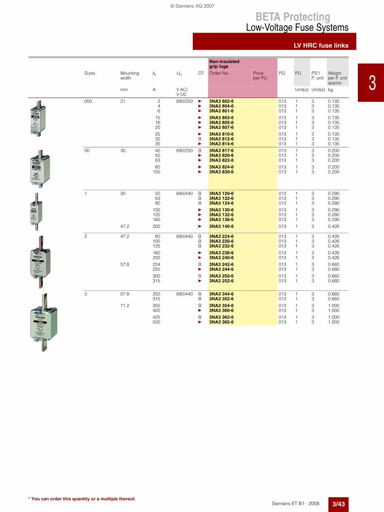
Non-insulated grip lugs
Sizes Mounting width
In Un DT Order No. Priceper PU
PG PU PS*/P. unit
Weightper P. unitapprox
mm A V AC/V DC
Unit(s) Unit(s) kg
LV HRC fuse links with front indicator, operational class gG
000 21 2 500/250 } 3NA3 802 013 1 3 0.1334 } 3NA3 804 013 1 3 0.1336 } 3NA3 801 013 1 3 0.133
10 } 3NA3 803 013 1 3 0.13316 } 3NA3 805 013 1 3 0.13320 } 3NA3 807 013 1 3 0.133
25 } 3NA3 810 013 1 3 0.13332 } 3NA3 812 013 1 3 0.13335 } 3NA3 814 013 1 3/90 0.133
40 } 3NA3 817 013 1 3 0.13350 } 3NA3 820 013 1 3/90 0.13363 } 3NA3 822 013 1 3/90 0.133
80 } 3NA3 824 013 1 3/90 0.133100 } 3NA3 830 013 1 3/90 0.133
125 400/-- A 3NY1 822 013 1 3 0.130160 B 3NY1 824 013 1 3 0.129
00 30 35 500/250 B 3NA3 814-7 013 1 3 0.20050 B 3NA3 820-7 013 1 3 0.20063 B 3NA3 822-7 013 1 3 0.200
80 B 3NA3 824-7 013 1 3 0.200100 B 3NA3 830-7 013 1 3 0.200125 } 3NA3 832 013 1 3 0.217
160 } 3NA3 836 013 1 3 0.217
0 30 6 500/440 B 3NA3 001 013 1 3 0.34010 B 3NA3 003 013 1 3 0.34016 B 3NA3 005 013 1 3 0.340
20 B 3NA3 007 013 1 3 0.34025 B 3NA3 010 013 1 3 0.34032 B 3NA3 012 013 1 3 0.340
35 B 3NA3 014 013 1 3 0.34040 B 3NA3 017 013 1 3 0.34050 B 3NA3 020 013 1 3 0.340
63 A 3NA3 022 013 1 3 0.34080 B 3NA3 024 013 1 3 0.340
100 A 3NA3 030 013 1 3 0.340
125 A 3NA3 032 013 1 3 0.340160 A 3NA3 036 013 1 3 0.340
1 30 16 500/440 B 3NA3 105 013 1 3 0.29020 B 3NA3 107 013 1 3 0.29025 B 3NA3 110 013 1 3 0.290
35 B 3NA3 114 013 1 3 0.30040 B 3NA3 117 013 1 3 0.30050 B 3NA3 120 013 1 3 0.300
63 } 3NA3 122 013 1 3 0.30080 } 3NA3 124 013 1 3 0.300
100 } 3NA3 130 013 1 3 0.300
125 } 3NA3 132 013 1 3 0.300160 } 3NA3 136 013 1 3 0.300
47.2 200 } 3NA3 140 013 1 3 0.440224 A 3NA3 142 013 1 3 0.440250 } 3NA3 144 013 1 3 0.440
© Siemens AG 2007

BETA ProtectingLow-Voltage Fuse Systems
LV HRC fuse links
3/42 Siemens ET B1 · 2008
12
3456789101112131415
1716
* You can order this quantity or a multiple thereof.
Non-insulated grip lugs
Sizes Mounting width
In Un DT Order No. Priceper PU
PG PU PS*/P. unit
Weightper P. unitapprox
mm A V AC/V DC
Unit(s) Unit(s) kg
2 47.2 35 500/440 B 3NA3 214 013 1 3 0.45350 B 3NA3 220 013 1 3 0.45363 A 3NA3 222 013 1 3 0.453
80 A 3NA3 224 013 1 3 0.453100 A 3NA3 230 013 1 3 0.453125 A 3NA3 232 013 1 3 0.453
160 } 3NA3 236 013 1 3 0.453200 } 3NA3 240 013 1 3 0.453
224 } 3NA3 242 013 1 3 0.453250 } 3NA3 244 013 1 3 0.453
57.8 300 A 3NA3 250 013 1 3 0.647315 } 3NA3 252 013 1 3 0.647
355 } 3NA3 254 013 1 3 0.647400 } 3NA3 260 013 1 3 0.647
3 57.8 200 500/440 B 3NA3 340 013 1 3 0.647224 B 3NA3 342 013 1 3 0.640250 A 3NA3 344 013 1 3 0.647
300 B 3NA3 350 013 1 3 0.647315 } 3NA3 352 013 1 3 0.647
355 A 3NA3 354 013 1 3 0.647400 } 3NA3 360 013 1 3 0.647
71.2 425 A 3NA3 362 013 1 3 1.000500 } 3NA3 365 013 1 3 1.000630 } 3NA3 372 013 1 3 1.000
Can only be used for 3NH3 530 LV HRC fuse base
4 (IEC design) 101.8 630 500/440 B 3NA3 472 013 1 1 2.500800 A 3NA3 475 013 1 1 2.500
1000 A 3NA3 480 013 1 1 2.500
1250 A 3NA3 482 013 1 1 2.500
Can only be used for 3NH7 520 LV HRC fuse base
4a 101.8 500 500/440 B 3NA3 665 013 1 1 2.700630 B 3NA3 672 013 1 1 2.700800 A 3NA3 675 013 1 1 2.700
1000 A 3NA3 680 013 1 1 2.8401250 A 3NA3 682 013 1 1 2.840
© Siemens AG 2007
BETA ProtectingLow-Voltage Fuse Systems
LV HRC fuse links
3/43Siemens ET B1 · 2008
12
34567891011121314151617* You can order this quantity or a multiple thereof.
Non-insulated grip lugs
Sizes Mounting width
In Un DT Order No. Priceper PU
PG PU PS*/P. unit
Weightper P. unitapprox
mm A V AC/V DC
Unit(s) Unit(s) kg
000 21 2 690/250 } 3NA3 802-6 013 1 3 0.1354 } 3NA3 804-6 013 1 3 0.1356 } 3NA3 801-6 013 1 3 0.135
10 } 3NA3 803-6 013 1 3 0.13516 } 3NA3 805-6 013 1 3 0.13520 } 3NA3 807-6 013 1 3 0.135
25 } 3NA3 810-6 013 1 3 0.13532 B 3NA3 812-6 013 1 3 0.13535 } 3NA3 814-6 013 1 3 0.135
00 30 40 690/250 B 3NA3 817-6 013 1 3 0.20050 } 3NA3 820-6 013 1 3 0.20063 } 3NA3 822-6 013 1 3 0.200
80 } 3NA3 824-6 013 1 3 0.200100 } 3NA3 830-6 013 1 3 0.200
1 30 50 690/440 B 3NA3 120-6 013 1 3 0.29063 B 3NA3 122-6 013 1 3 0.29080 B 3NA3 124-6 013 1 3 0.290
100 } 3NA3 130-6 013 1 3 0.290125 } 3NA3 132-6 013 1 3 0.290160 } 3NA3 136-6 013 1 3 0.290
47.2 200 } 3NA3 140-6 013 1 3 0.426
2 47.2 80 690/440 B 3NA3 224-6 013 1 3 0.426100 B 3NA3 230-6 013 1 3 0.426125 B 3NA3 232-6 013 1 3 0.426
160 } 3NA3 236-6 013 1 3 0.426200 } 3NA3 240-6 013 1 3 0.426
57.8 224 B 3NA3 242-6 013 1 3 0.660250 } 3NA3 244-6 013 1 3 0.680
300 B 3NA3 250-6 013 1 3 0.660315 } 3NA3 252-6 013 1 3 0.680
3 57.8 250 690/440 B 3NA3 344-6 013 1 3 0.660315 B 3NA3 352-6 013 1 3 0.660
71.2 355 B 3NA3 354-6 013 1 3 1.000400 } 3NA3 360-6 013 1 3 1.000
425 B 3NA3 362-6 013 1 3 1.000500 } 3NA3 365-6 013 1 3 1.000
© Siemens AG 2007

BETA ProtectingLow-Voltage Fuse Systems
LV HRC fuse links
3/44 Siemens ET B1 · 2008
12
3456789101112131415
1716
* You can order this quantity or a multiple thereof.
Non-insulated grip lugs
Sizes Mounting width
In Un DT Order No. Priceper PU
PG PU PS*/P. unit
Weightper P. unitapprox
mm A V AC/V DC
Unit(s) Unit(s) kg
LV HRC fuse links with front indicator, operational class aM
000 21 6 500/-- B 3ND1 801 014 1 3 0.13010 B 3ND1 803 014 1 3 0.13016 B 3ND1 805 014 1 3 0.130
20 B 3ND1 807 014 1 3 0.13025 B 3ND1 810 014 1 3 0.13032 B 3ND1 812 014 1 3 0.130
35 B 3ND1 814 014 1 3 0.13040 B 3ND1 817 014 1 3 0.13050 B 3ND1 820 014 1 3 0.130
63 B 3ND1 822 014 1 3 0.13080 B 3ND1 824 014 1 3 0.130
00 30 100 500/-- B 3ND1 830 014 1 3 0.192125 B 3ND1 832 014 1 3 0.192160 B 3ND1 836 014 1 3 0.192
1 30 63 690/-- B 3ND2 122 014 1 3 0.29080 B 3ND2 124 014 1 3 0.290
100 B 3ND2 130 014 1 3 0.440
47.2 125 B 3ND2 132 014 1 3 0.440160 B 3ND2 136 014 1 3 0.440
200 B 3ND2 140 014 1 3 0.440250 B 3ND2 144 014 1 3 0.440
2 47.2 125 690/-- B 3ND2 232 014 1 3 0.440160 B 3ND2 236 014 1 3 0.440
200 B 3ND2 240 014 1 3 0.440250 B 3ND2 244 014 1 3 0.440
57.8 315 B 3ND2 252 014 1 3 0.650355 B 3ND2 254 014 1 3 0.650400 A 3ND2 260 014 1 3 0.650
3 57.8 315 690/-- B 3ND2 352 014 1 3 0.650355 B 3ND2 354 014 1 3 0.650400 B 3ND2 360 014 1 3 0.650
71.2 500 B 3ND1 365 014 1 3 1.030630 B 3ND1 372 014 1 3 1.000
© Siemens AG 2007

BETA ProtectingLow-Voltage Fuse Systems
LV HRC fuse links
3/45Siemens ET B1 · 2008
12
34567891011121314151617* You can order this quantity or a multiple thereof.
■ Dimensional drawings
LV HRC fuse links, operational class gG
Sizes In Un Type Dimensions
A V b h1 h2 t1 t2000 2 ... 100 500 V AC/250 V DC 3NA3 8../-7 21 54 80 45 8
2 ... 35 690 V AC/250 V DC 3NA3 8..-62 ... 100 500 V AC/250 V DC 3NA6 8..
10 ... 100 400 AC 3NA6 8..-42 ... 35 690 V AC/250 V DC 3NA6 8..-6
10 ... 100 500 V AC/250 V DC 3NA7 8..2 ... 35 690 V AC/250 V DC 3NA7 8..-6
00 35 ... 160 500 V AC/250 V DC 3NA3 8.. 30 54 80 45 1440 ... 100 690 V AC/250 V DC 3NA3 8..-680 ... 160 500 V AC/250 V DC 3NA6 8../-780 ... 160 400 AC 3NA6 8..-4 (KK)40 ... 100 690 V AC/250 V DC 3NA6 8..-680 ... 160 500 V AC/250 V DC 3NA7 8../-740 ... 100 690 V AC/250 V DC 3NA7 8..-6
0 6 ... 160 500 V AC/440 V DC 3NA3 0.. 30 67 126 45 14
1 16 ... 160 500 V AC/440 V DC 3NA3 1.. 30 75 137 50 1550 ... 160 690 V AC/440 V DC 3NA3 1..-616 ... 160 500 V AC/440 V DC 3NA6 1..35 ... 160 400 AC 3NA6 1..-450 ... 160 690 V AC/440 V DC 3NA6 1..-616 ... 160 500 V AC/440 V DC 3NA7 1..50 ... 160 690 V AC/440 V DC 3NA7 1..-6
200 ... 250 500 V AC/440 V DC 3NA3 1.. 47 75 137 51 9200 690 V AC/440 V DC 3NA3 1..-6200 ... 250 500 V AC/440 V DC 3NA6 1..200 ... 250 400 AC 3NA6 1..-4200 690 V AC/440 V DC 3NA6 1..-6200 ... 250 500 V AC/440 V DC 3NA7 1..200 690 V AC/440 V DC 3NA7 1..-6
2 35 ... 250 500 V AC/440 V DC 3NA3 2.. 47 75 151 58 1080 ... 200 690 V AC/440 V DC 3NA3 2..-635 ... 250 500 V AC/440 V DC 3NA6 2..50 ... 250 400 AC 3NA6 2..-480 ... 200 690 V AC/440 V DC 3NA6 2..-635 ... 250 500 V AC/440 V DC 3NA7 2..80 ... 200 690 V AC/440 V DC 3NA7 2..-6
300 ... 400 500 V AC/440 V DC 3NA3 2.. 58 74 151 59 13224 ... 250 690 V AC/440 V DC 3NA3 2..-6300 ... 400 500 V AC/440 V DC 3NA6 2..300 ... 400 400 AC 3NA6 2..-4224 ... 315 690 V AC/440 V DC 3NA6 2..-6300 ... 400 500 V AC/440 V DC 3NA7 2..224 ... 315 690 V AC/440 V DC 3NA7 2..-6
3 200 ... 400 500 V AC/440 V DC 3NA3 3.. 58 74 151 71 13250, 315 690 V AC/440 V DC 3NA3 3..-6
425 ... 630 500 V AC/440 V DC 3NA3 3.. 71 74 151 70 13355 ... 500 690 V AC/440 V DC 3NA3 3..-6
4 630 ... 1250 500 V AC/440 V DC 3NA3 4.. See adjacent drawing
4a 500 ... 1250 500 V AC/440 V DC 3NA3 6.. 102 97 201 95 20
t1
I2_10899
b
t2
h 1 h 2
202
I2_11335
65 55
9010
2
Sizes 000 to 3 and 4a
Size 4 (IEC design)
© Siemens AG 2007
BETA ProtectingLow-Voltage Fuse Systems
LV HRC fuse links
3/46 Siemens ET B1 · 2008
3
* You can order this quantity or a multiple thereof.
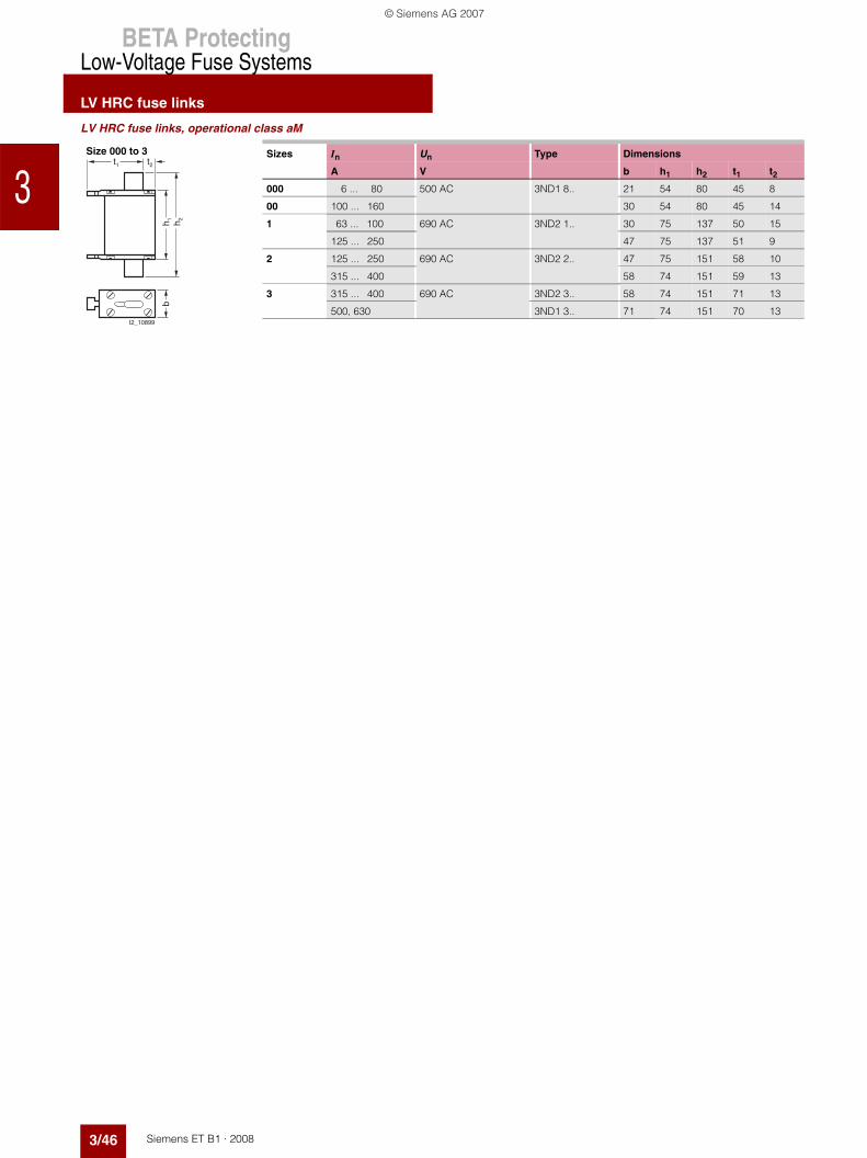
LV HRC fuse links, operational class aM
Sizes In Un Type Dimensions
A V b h1 h2 t1 t2000 6 ... 80 500 AC 3ND1 8.. 21 54 80 45 8
00 100 ... 160 30 54 80 45 14
1 63 ... 100 690 AC 3ND2 1.. 30 75 137 50 15
125 ... 250 47 75 137 51 9
2 125 ... 250 690 AC 3ND2 2.. 47 75 151 58 10
315 ... 400 58 74 151 59 13
3 315 ... 400 690 AC 3ND2 3.. 58 74 151 71 13
500, 630 3ND1 3.. 71 74 151 70 13
t1
I2_10899
bt2
h 1 h 2
Size 000 to 3
© Siemens AG 2007

BETA ProtectingLow-Voltage Fuse Systems
LV HRC signal detectors
3/47Siemens ET B1 · 2008
12
34567891011121314151617* You can order this quantity or a multiple thereof.
■ Overview
LV HRC signal detectors are used for remote indication that the LV HRC fuse links have been tripped. 3 different solutions are available:• 3NX1 021 signal detectors with signal detector link 3• 3NX1 024 signal detector top• 5TT3 170 fuse monitors.
The LV HRC signal detectors with signal detector link support monitoring of LV HRC fuse links with non-insulated grip lugsof sizes 000 to 4 at 10 A or more.
The signal detector link is connected in parallel to the LV HRC fuse link. In the event of a fault, the LV HRC fuse links are released simul-taneously with the LV HRC fuse signaling link. A tripping pin switches a floating microswitch.
The signal detector top can be used with LV HRC fuse links, sizes 000, 00, 1 and 2, which are equipped with non-insulated grip lugs and have a front indicator or combination alarm. It is simply plugged into the grip lugs.
If a fuse is tripped, the front indicator springs open and switches a floating microswitch. This solution should not be used for safety-relevant plants. For this purpose, we recommend our electronic fuse monitors.
■ Benefits
LV HRC signal detectors reliably indicate when a fuse has tripped. Tripped fuses are quickly located. This saves time and increases plant availability.
■ Selection and ordering data
$ LV HRC fuse link% Signal detector& Microswitch( Spring contact) Hinged lid* Signal detector links
I2_1
3744
1
6
5
3
4
2
$ LV HRC fuse link% Front indicator & Signal detector tops( Rocker/lever arm
$
%
&
(
Sizes DT Order No. Priceper PU
PG PU PS*/P. unit
Weightper P. unitapprox
Unit(s) Unit(s) kg
LV HRC signal detectors 000 ... 4 A 3NX1 021 014 1 1 0.036Only for SIEMENS 3NA3, 3NA7 and 3ND LV HRC fuse links with non-insulated grip lugs• Rated voltage up to 690 V AC/600 V DC• Contact: microswitch 250 V AC, 6 A• Connection: flat termination 2.3 mm
Signal detector links 000 ... 4• Rated voltage up to 690 V AC/ 600 V DC
Response value > 9 V; 2.5 A; for standard applications
A 3NX1 022 014 1 3 0.015
Response value > 2 V; 7 A; only for meshed networks
C 3NX1 023 014 1 3 0.015
Signal detector tops 000, 00, 1, 2 } 3NX1 024 014 1 1 0.010
Only for SIEMENS 3NA3, 3NA7 and 3ND LV HRC fuse links with non-insulated grip lugs• Rated voltage up to 690 V AC/600 V DC• Contact: microswitch 230 V AC, 5 A, 1 CO• Connection: flat termination 2.3 mm
© Siemens AG 2007

BETA ProtectingLow-Voltage Fuse Systems
LV HRC signal detectors
3/48 Siemens ET B1 · 2008
3
* You can order this quantity or a multiple thereof.
For more information on fuse monitors, please refer to the chapter "Monitoring of plants and devices".
■ Dimensional drawings
■ Schematics
Ue In Uc MW DT Order No. Priceper PU
PG PU PS*/P. unit
Weightper P. unitapprox
V AC A V Unit(s) Unit(s) kg
Fuse monitors
For all low-voltage fuse systems.Can be used in asymmetric systems afflicted with harmonics and regenerative feedback motors. Alarm also for disconnected loads.
230 4 3x 380 ... 415 2 } 5TT3 170 027 1 1 0.150
LV HRC signal detectors Signal detector links Signal detector tops
3NX1 021 3NX1 022, 3NX1 023 3NX1 024
115
40
I2_0
7856
a
2515
I2_0
7857
a
11
7
66
� �
� � � �
��
����
� � � �
����
��
� � � � � � �
Fuse monitors
5TT3 170
36
L1 L2 L3
14
L1 L2 L3
15
5 4364
45 90
I2_1
1512
LV HRC signal detectorsSignal detector top
Fuse monitors
3NX1 0213NX1 024
5TT3 170
" �N NO NC
���� ����
�����������
© Siemens AG 2007

BETA ProtectingLow-Voltage Fuse Systems
LV HRC fuse bases
3/49Siemens ET B1 · 2008
12
34567891011121314151617* You can order this quantity or a multiple thereof.
■ Overview
Terminals for all applicationsTerminals are as different as the requirements of individual systems.
Flat terminals with screws are suitable for connecting busbars or ca-ble lugs. They have a torsion-proof screw connection with shim, spring washer and nut. When tightening the nut, always ensure compliance with the specified torque due to the considerable leverage effect.The double busbar terminal differs from the flat connection in that it supports connection of two busbars, one on the top and one at the bottom of the flat connection.
The modern box terminal ensures efficient and reliable connection to the conductors. They support connection of conductors with or without end sleeves.
In the case of flat terminal with nut, connection of the nut to the terminal lug is torsion-proof. When tightening the nut, the torque must be observed because of the considerable leverage effect.
Up to three conductors can be clamped to the terminal strip.
The plug-in terminal is equipped for connecting two conductors. One conductor can be clamped to the saddle-type terminal.
© Siemens AG 2007

BETA ProtectingLow-Voltage Fuse Systems
LV HRC fuse bases
3/50 Siemens ET B1 · 2008
3
* You can order this quantity or a multiple thereof.
■ Benefits
■ Technical specifications
• The silver-plated Lyra contact provides a large contact area for the contact pin of the LV HRC fuse link. This improves heat transmission and lowers the temperature. It also minimizes ageing of the fuse link in the maximum load range, in particular when using SITOR fuses
• The large contact area also facilitates replacement of LV HRC fuse links
• The spring washer tensioning the contact is mechanically galvanized. This will prevent hydrogen embrittlement. The contact is resistant to aging and there will be no dreaded annealing of contacts, which considerably improves operating safety.
LV HRC fuse bases, LV HRC bus-mounting bases
Size 000/00 0 1 2 3 4 4a
Standards IEC 60269-1, -2; EN 60269-1; DIN VDE 0636-2
Rated current In A 160 160 250 400 630 1250
Rated voltage Un V AC 690 690 (Also suitable for 1000 V SITOR fuse links)V DC 250 440
Rated breaking capacity kA AC 120
kA DC 25
Flat terminals
Screw M8 M10 M12 M16Nut M8 --Max. tightening torque Nm 14 38 65
Plug-in terminals
Conductor cross-section mm2 2.5 ... 50 --
Saddle-type terminals
Conductor cross-section mm2 6 ... 70 --
Box terminals
Conductor cross-section mm2 2.5 ... 50
Terminal strip
Conductor cross-section, 3-wire mm2 1.5 ... 16 --Max. torque for attachment of LV HRC fuse base
Nm 2 2.5 --
LV HRC fuse bases with slewing equipment LV HRC fuse bases with slewing equipment
Size 000/00 1 2/3 4a
Rated voltage Un V AC 690V DC 440
Power loss W 4 5 20 32
Flat terminals
Screw M8 M10 M12 M16Nut M8 --Max. tightening torque Nm 14 38 65
© Siemens AG 2007
BETA ProtectingLow-Voltage Fuse Systems
LV HRC fuse bases
3/51Siemens ET B1 · 2008
12
34567891011121314151617* You can order this quantity or a multiple thereof.
■ Selection and ordering data
Sizes In Version DT Order No. Priceper PU
PG PU PS*/P. unit
Weightper P. unitapprox
A Unit(s) Unit(s) kg
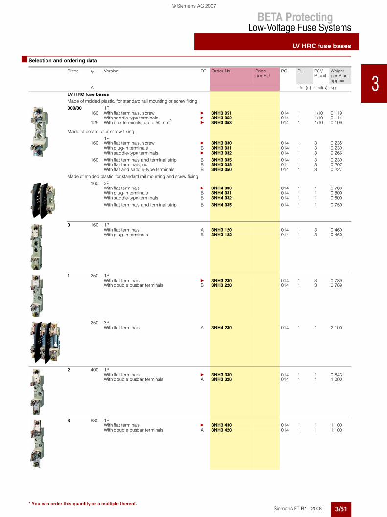
LV HRC fuse bases
Made of molded plastic, for standard rail mounting or screw fixing
000/00 1P160 With flat terminals, screw } 3NH3 051 014 1 1/10 0.119
With saddle-type terminals } 3NH3 052 014 1 1/10 0.114125 With box terminals, up to 50 mm2
} 3NH3 053 014 1 1/10 0.109
Made of ceramic for screw fixing
1P160 With flat terminals, screw } 3NH3 030 014 1 3 0.235
With plug-in terminals B 3NH3 031 014 1 3 0.230With saddle-type terminals } 3NH3 032 014 1 3 0.266
160 With flat terminals and terminal strip B 3NH3 035 014 1 3 0.230With flat terminals, nut B 3NH3 038 014 1 3 0.207With flat and saddle-type terminals B 3NH3 050 014 1 3 0.227
Made of molded plastic, for standard rail mounting and screw fixing
160 3PWith flat terminals } 3NH4 030 014 1 1 0.700With plug-in terminals B 3NH4 031 014 1 1 0.800With saddle-type terminals B 3NH4 032 014 1 1 0.800
With flat terminals and terminal strip B 3NH4 035 014 1 1 0.750
0 160 1PWith flat terminals A 3NH3 120 014 1 3 0.460With plug-in terminals B 3NH3 122 014 1 3 0.460
1 250 1PWith flat terminals } 3NH3 230 014 1 3 0.789With double busbar terminals B 3NH3 220 014 1 3 0.789
250 3PWith flat terminals A 3NH4 230 014 1 1 2.100
2 400 1PWith flat terminals } 3NH3 330 014 1 1 0.843With double busbar terminals A 3NH3 320 014 1 1 1.000
3 630 1PWith flat terminals } 3NH3 430 014 1 1 1.100With double busbar terminals A 3NH3 420 014 1 1 1.100
© Siemens AG 2007

BETA ProtectingLow-Voltage Fuse Systems
LV HRC fuse bases
3/52 Siemens ET B1 · 2008
3
* You can order this quantity or a multiple thereof.
Sizes In Version DT Order No. Priceper PU
PG PU PS*/P. unit
Weightper P. unitapprox
A Unit(s) Unit(s) kg
4 1250 1P(IEC design)
With flat terminals A 3NH3 530 014 1 1 3.000
LV HRC bus-mounting bases for busbars
12 x 5 mm to 12 x 10 mm, Busbar spacing 40 mm
000/00 160 1PWith top saddle-type terminals B 3NH3 036 014 1 1 0.150With bottom saddle-type terminals B 3NH3 037 014 1 1 0.150Terminal strip, top B 3NH3 048 014 1 1 0.150
000/00 80 3P, in tandem design3 outgoing feeders, top and bottom With saddle-type terminalsWith 4 barriers B 3NH4 037 014 1 1 0.800With 2 non-interrupted barriers B 3NH4 045 014 1 1 0.800
LV HRC fuse bases with slewing equipment
With flat terminal and additional saddle-type terminals (included)
000/00 160 1P
With screw fixing for mounting plate A 3NH7 030 014 1 1 1.000With claw fixing for non-perforated busbar
B 3NH7 031 014 1 1/3 1.000
With screw fixing for perforated busbar
B 3NH7 032 014 1 1/3 1.000
1 250 With screw fixing for mounting plate A 3NH7 230 014 1 1 2.500With claw fixing for non-perforated busbar
B 3NH7 231 014 1 1 2.500
With screw fixing for perforated busbar
B 3NH7 232 014 1 1 2.500
Can also be used for fuse links of size 2
3 630 With screw fixing for mounting plate B 3NH7 330 014 1 1 4.800With claw fixing for non-perforated busbar
B 3NH7 331 014 1 1 4.800
With screw fixing for perforated busbar, can be used as disconnector
B 3NH7 332 014 1 1 4.800
© Siemens AG 2007

BETA ProtectingLow-Voltage Fuse Systems
LV HRC fuse bases
3/53Siemens ET B1 · 2008
12
34567891011121314151617* You can order this quantity or a multiple thereof.
Sizes In Version DT Order No. Priceper PU
PG PU PS*/P. unit
Weightper P. unitapprox
A Unit(s) Unit(s) kg
4a 1250 With screw fixing for mounting plate
A 3NH7 520 014 1 1 5.200
LV HRC contact covers for LV HRC fuse bases
000/00 Touch protection for contact pieces } 3NX3 105 014 1 2/20 0.0130 B 3NX3 114 014 1 2/40 0.0101 } 3NX3 106 014 1 2/20 0.027
2 } 3NX3 107 014 1 2/12 0.0313 } 3NX3 108 014 1 2/10 0.038
LV HRC partitions for LV HRC fuse basesAs intermediate phase and end barrier
000/00 Type
3NH3 0/3NH4 0 } 3NX2 023 014 1 2 0.0250 3NH3 1 B 3NX2 030 014 1 2 0.0501 3NH3 2 } 3NX2 024 014 1 2 0.053
2 3NH3 3 } 3NX2 025 014 1 2 0.0663 3NH3 4 } 3NX2 026 014 1 2 0.101
LV HRC protective covers IP2X For LV HRC fuse bases
000/00 1P and 3P B 3NX3 115 014 1 10 0.039
LV HRC covers
For plugging into IP2X LV HRC protective covers B 3NX3 116 014 1 10 0.014
LV HRC contact covers for LV HRC bus-mounting bases
Touch protection for contact pieces
Outgoing terminal } 3NX3 105 014 1 2/20 0.013Incoming terminal B 3NX3 113 014 1 2/50 0.006
LV HRC partitions for 3NH3 0 LV HRC bus-mounting bases
As phase barrier C 3NX2 027 014 1 2 0.017
As end barrier C 3NX2 028 014 1 2/50 0.020
© Siemens AG 2007

BETA ProtectingLow-Voltage Fuse Systems
LV HRC fuse bases
3/54 Siemens ET B1 · 2008
3
* You can order this quantity or a multiple thereof.
Sizes Version DT Order No. Priceper PU
PG PU PS*/P. unit
Weightper P. unitapprox
Unit(s) Unit(s) kg
Non-interrupted barriers
For 3NH4 0 LV HRC bus-mounting bases C 3NX2 031 014 1 2/30 0.050
Fuse pullers
000 ... 4 For LV HRC fuse links
Without sleeve } 3NX1 013 014 1 1 0.280
With sleeve } 3NX1 014 014 1 1 0.480
Isolating links For LV HRC fuse bases and
fuse switch disconnectors
With insulated grip lugs
000/00 Silver-plated } 3NG1 002 014 1 3/30 0.0800 C 3NG1 102 014 1 1/10 0.110
1 } 3NG1 202 014 1 1/10 0.1702 } 3NG1 302 014 1 1/5 0.2403 } 3NG1 402 014 1 1/5 0.290
With non-insulated grip lugs
4 Tinned B 3NG1 503 014 1 6 0.7084a Nickel-plated B 3NG1 505 014 1 1/5 0.730
Fuse-base covers
For LV HRC fuse bases, red with yellow inscription (German) "Power supply isolating point"
000/00 C 3NX1 003 014 1 3 0.0501, 2, 3 C 3NX1 004 014 1 3 0.100
© Siemens AG 2007

BETA ProtectingLow-Voltage Fuse Systems
LV HRC fuse bases
3/55Siemens ET B1 · 2008
12
34567891011121314151617* You can order this quantity or a multiple thereof.
■ Dimensional drawings
LV HRC fuse bases
1) Size 4 LV HRC fuse links are also screwed onto the base.2) LV HRC bus-mounting bases are only connected on one side using terminals,
the second connection is made through the bottom of the base.
Size 000/00 to 3
3NH3 051 3NH3 052 3NH3 053
Sizes In Num- ber of poles
Connection Type Dimensions
Size 41) A b1 b2 h1 h2 t1 t2 t3
000/00 160 1P M8 plug-in terminal 3NH3 0.. 30 34 102 122 24 40 60Saddle-type terminal 29Flat terminal 23
3P M8 plug-in terminal 3NH4 0.. 30 102Saddle-type terminal 29Flat terminal 23
1P Saddle-type terminal LV HRC bus mounting base2)
3NH3 0..
29 37 – 95 28 44 64Terminal strip 26 102
0 160 1P Flat terminal 3NH3 1.. 23 38 150 173 24 39 60Plug terminal 30
1 250 1P M10 flat terminal 3NH3 2.. 35 49 177 201 35 55 84Double busbar terminal
3P M10 flat terminal 3NH4 2.. 163
2 400 1P M10 flat terminal 3NH3 3.. 35 49 202 226 35 55 90Double busbar terminal
3 630 1P M12 flat terminal 3NH3 4.. 35 49 212 241 35 55 101Double busbar terminal
4 1250 1P M12 flat terminal 3NH3 5.. 50 102 270 max. 307
51 1161) 144
4a Can only be used in bases with slewing equipment
LV HRC bus-mounting base2)
1P
b1
b2
h 1 h 2
t1
t2
t3
I2_1
1346
101
4,521,5
23
3556 I2
_128
4833,539
121
4,521,5
20
3556 I2
_128
4933,539
108
120
4,518
3556 I2
_128
50
33,539
99 117
I2_1
1347t1
b2
b1
h 2h 1
t2t3
h 1
t1
t2
t3
b1
b2
I2_1
1348
© Siemens AG 2007

BETA ProtectingLow-Voltage Fuse Systems
LV HRC fuse bases
3/56 Siemens ET B1 · 2008
3
* You can order this quantity or a multiple thereof.
LV HRC bus-mounting bases in tandem design LV HRC fuse bases with slewing equipmentBusbar center-to-center clearance 40 mm3NH4 037, 3NH4 045
Sizes 000/00 to 4a
I2_0
6498
a33 33107
213,
5
4491
28
230
I2_1
1357
ao
d
eb
c
ln
m
Sizes In Type Dimensions
A a b c d e l m n o
000/00 160 3NH7 03. 44 149 45 88.5 22.5 120 17 18 200
1 250 3NH7 23. 68 230 68 123.5 23 177 25 40 300
2/3 630 3NH7 33. 90 270 96 153.5 15.5 220.5 30.5 35 350
4a 1250 3NH7 520 116 350 154.5 217.5 69 270 40 26 440
© Siemens AG 2007

BETA ProtectingLow-Voltage Fuse Systems
LV HRC fuse bases
3/57Siemens ET B1 · 2008
12
34567891011121314151617* You can order this quantity or a multiple thereof.
LV HRC contact covers for LV HRC fuse bases
Sizes 000/00 to 3, 3NX3 10
Sizes Type Dimensions
a b c d e
000/00 3NX3 105 38 47.5 34 11.5 30
1 3NX3 106 61.5 57 42.5 35 46
2 3NX3 107 74 65 51 35 46
3 3NX3 108 81.5 77.5 57.5 35 46
3NX3 115 LV HRC protective cover, with 3NX3 116 LV HRC cover
Size 000/00, degree of protection IP2X
I2_1
1365a
e
db
c
�� �
���
��
������
��
LV HRC partitions
Size 000/00 Sizes 0 to 33NX3 023 3NX2 030, 3NX2 024 to 3NX2 026
Sizes Type Dimensions
a b c d
0 3NX2 030 87.6 178.5 7.7 12.3
1 3NX2 024 107.3 202.5 7.7 12.3
2 3NX2 025 115.3 227.5 14.2 25.1
3 3NX2 026 129.8 242 20.2 37.2
������
��
� �
�
� �
�
� �
�
�
� �
��
�� �
�
��
������
�
�
�
��
�
��
�
�
LV HRC contact covers for LV HRC bus-mounting bases
for 1-pole version and tandem design,3NX3 105
3P,3NX3 113
LV HRC partitions
Phase barriers End barrier For LV HRC fuse bases in tandem design3NX2 027 3NX2 028 3NX2 031
I2_1
1367
3047,5
34
38
5030
I2_11368
11,5
114
82
I2_0
6499
a
113,
5
86,5
I2_06502a
230
81,5
I2_0
6684
a
© Siemens AG 2007

BETA ProtectingLow-Voltage Fuse Systems
LV HRC fuse bases
3/58 Siemens ET B1 · 2008
3
* You can order this quantity or a multiple thereof.
Fuse puller Sizes 000 to 43NX1 013 (without sleeve), 3NX1 014 (with sleeve)
Isolating linksWith insulated grip lug, sizes 000/00 to 33NG1 .02 Sizes Type Dimensions
a b c d e f g h
000/00 3NG1 002 44 15 48 78 54 20.5 8 19
0 3NG1 102 60.5 15 48 125 68 20.5 8 19
1 3NG1 202 61 20 53 135 72 23 9 24
2 3NG1 302 61 26 61 150 72 23 9 29
3 3NG1 402 61 32 73 150 72 23 9 36
Isolating links with non-insulated grip lugs
Size 4 Size 4a3NG1 503 3NG1 505
27,5
47,5
68 125
13024
66
136
350
92,526
I2_06503a
Sleeve
a e d
I2_06490
g
b
h
c3,5
13 6 f
I2_06511a
8
68200
30
150
16
61
32
5085
10550
85105
9
6 4053
,588 19
7
I2_06685a
© Siemens AG 2007

BETA ProtectingLow-Voltage Fuse Systems
LV HRC fuse bases
3/59Siemens ET B1 · 2008
12
34567891011121314151617* You can order this quantity or a multiple thereof.
■ More information
Space requirements when installing LV HRC fuse bases
1) Placing an additional base on the barrier and plug-on part does not increase the distance, rather the bases lie flat directly on top of one another.
2) This measurement specifies the required overall mounting depth with base d and the overall mounting height h.
3) If the bases are installed directly on a side wall in the distribution board, one spacer part can be broken off. This would reduce the distance measurement.
1 LV HRC fuse base, 3P 3 LV HRC fuse bases, 1P LV HRC partition
I2_1
1361
I2_1
1362
I2_1
1363
Partition
Spacer
h
d
Sizes Mounting width (mm) of LV HRC fuse bases Mounting height (mm)
Mounting depth(mm)
1 unit, 3P 3 units, 1P Distance through spacer
3NX2 0.. partitions with matching bases2)
Base with phase barrier, with-out end barrier
Base with phase and 2 end barriers
Base with phase barrier, with-out end barrier
Base with phase and 2 end barriers
h d
000/00 102 106 100 1041) 2 138 86
LV HRC bus-mounting bases see page 3/55 – 114 90
0 – – 128 142 7 178 90
1 163 177 158 172 7 202 110
2 – – 184 224 20 227 118
3 – – 208 272 32 242 132
4 Installation without barriers; for mounting see page 3/55 n/a
4a Can only be used in bases with slewing equipment n/a
© Siemens AG 2007

BETA ProtectingLow-Voltage Fuse Systems
LV HRC fuse bases
3/60 Siemens ET B1 · 2008
3
* You can order this quantity or a multiple thereof.
Drill hole dimensions for base plate mountingLV HRC fuse bases,
Sizes000/00 and 0
Sizes 1 to 3
Size4
Sizes Type Dimensions
b1 b2 h1 h2 l
000/00 3NH3 0.. 17 – 48 25 7.5
0 3NH3 1.. 19 – 74 25 7.5
1 3NH3 2.. 9 30 88 25 10.5
2 3NH3 3.. 9 30 100 25 10.5
3 3NH3 4.. 9 30 108 25 10.5
4 3NH3 530 36 30 141 25 13
LV HRC fuse bases, 3PSize 000/00 Size 1
Sizes Type Dimensions
b1 b2 h1 h2 l
000/00 3NH4 0.. 15 70 46 – 7.5
1 3NH4 230 26 110.5 88 25 10
b1
h 1
I2_1
1349
h 2h 1
l
���������
��
�
�
�
��
��
b1
I2_1
1351
b1b2
h 1h 1
h 2l
b1
I2_1
1352
b1b2
h 1h 1
l
b1
I2_1
1353
b1b2
h 1h 1
h 2l
© Siemens AG 2007
BETA ProtectingLow-Voltage Fuse Systems
LV HRC fuse bases
3/61Siemens ET B1 · 2008
12
34567891011121314151617* You can order this quantity or a multiple thereof.
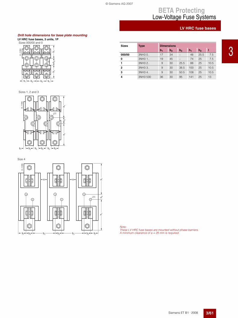
Drill hole dimensions for base plate mountingLV HRC fuse bases, 3 units, 1PSizes 000/00 and 0
Sizes Type Dimensions
b1 b2 b3 h1 h2 l
000/00 3NH3 0.. 17 34 – 48 25.5 7.5
0 3NH3 1.. 19 45 – 74 25 7.5
1 3NH3 2.. 9 30 25.5 88 25 10.5
2 3NH3 3.. 9 30 38.5 100 25 10.5
3 3NH3 4.. 9 30 50.5 108 25 10.5
4 3NH3 530 36 30 95 141 25 13b1
h 1
I2_1
1354
h 2h 1
l
b2b2b1
Sizes 1, 2 and 3
b3b2b3b2
h 1
b2
I2_1
1355
h 2h 1
b1
l
Size 4
Note:These LV HRC fuse bases are mounted without phase barriers. A minimum clearance of a = 25 mm is required.b1
I2_1
1356
b2
h 1h 1
h 2
aa
b3 b2 b1b2b3
l
© Siemens AG 2007

BETA ProtectingLow-Voltage Fuse Systems
LV HRC fuse bases
3/62 Siemens ET B1 · 2008
3
* You can order this quantity or a multiple thereof.
Space requirements when installing LV HRC bus-mounting bases
Space requirements for3-piece, 1-pole LV HRC bus-mounting bases, staggered
82
I2_1
1364
71
38
Sad
dle-
type
term
inal
con
nect
ion:
175
Ter
min
al s
trip
: 182
Drill hole dimensions for base plate mounting
Size 000/00
Sizes1 and 2/3
Size 4a
������
�
�
�
���� ��
�
������
�
��
���� ��
�
h2
f
h1 h1
� k
g
I2_1
1360
g
Sizes In Type Dimensions
A f g h1 h2 ∅k p
000/00 160 3NH7 03. 79 – 9.5 25 7 20
1 250 3NH7 23. 102.5 25 19 30 10.5 25
2/3 630 3NH7 33. 122.5 25 30 30 10.5 40
4a 1250 3NH7 520 170 30 31.5 45 13 50
© Siemens AG 2007