english - elanportal.comelanportal.com/supportdocs/catalog/sc1_installation_manual.pdfp/n 9905976...
TRANSCRIPT
SC1 – Serial Controller Quick Install Guide
Items in Box• SC1• RJ-45 to RJ-45 Crossover cable• Installation Manual• Power supply
IntroductionThe ELAN SC1 is a serial to ViaNet interface that provides integration of legacy ViaNet devices with the ELAN gSC2, gSC10 and g1 (g Series) controllers. Specifically the SC1 allows the g Series controllers to communicate with the ELAN S1616A, M86A and TS2 and TS2L. It may provide interface to additional ELAN ViaNet legacy components, but components other than those listed in the previous sentence have not been tested and are not supported. You should test the SC1 with devices other than those listed above prior to committing your customer to an unsupported upgrade path.
Features• Converts Serial protocol communications to ELAN ViaNet protocol communications• Convenient RJ-45 to RJ-45 connections• LED activity indicator for easy troubleshooting • g! Controller Programming
Please consult the latest SC1 integration note for proper g! System Controller configuration.
Limited Warranty ELAN HOME SYSTEMS, LLC, a Core Brands, LLC company (“ELAN”) warrants the SC-1 Serial Device Controller to be free from defects in materials and workmanship for the period of two years (2 years) from date of purchase. If within the applicable warranty period above purchaser discovers that such item was not as warranted above and promptly notifies ELAN in writing, ELAN shall repair or replace the item at the company’s option. This warranty shall not apply (a) to equipment not manufactured by ELAN, (b) to equipment which shall have been installed by other than an ELAN authorized installer, (c) to installed equipment which is not installed to ELAN’s specifications, (d) to equipment which shall have been repaired or altered by others than ELAN, (e) to equipment which shall have been subjected to negligence, accident, or damage by circumstances beyond ELAN’s control, including, but not limited to, lightning, flood, electrical surge, tornado, earthquake, or other catastrophic events beyond ELAN’s control, or to improper operation, maintenance or storage, or to other than normal use of service. With respect to equipment sold by, but not manufactured by ELAN, the warranty obligations of ELAN shall in all respects conform to the warranty actually extended to ELAN by its supplier. The foregoing warranties do not cover reimbursement for labor, transportation, removal, installation or other expenses which may be incurred in connection with repair or replacement.
Except as may be expressly provided and authorized in writing by ELAN, ELAN shall not be subject to any other obligations or liabilities whatsoever with respect to equipment manufactured by ELAN or services rendered by ELAN.
THE FOREGOING WARRANTIES ARE EXCLUSIVE AND IN LIEU OF ALL OTHER EXPRESSED AND IMPLIED WARRANTIES EXCEPT WARRANTIES OF TITLE, INCLUDING BUT NOT LIMITED TO IMPLIED WARRANTIES OF MERCHANTABILITY AND FITNESS FOR A PARTICULAR PURPOSE.
ATTENTION: TO OUR VALUED CONSUMERSTo ensure that consumers obtain quality pre-sale and after-sale support and service, ELAN Home Systems products are sold exclusively through authorized dealers. ELAN products are not sold online. The warranties on ELAN products are NOT VALID if the products have been purchased from an unauthorized dealer or an online E-tailer.
To determine if your ELAN reseller is authorized, please contact ELAN Home Systems at (707) 283-5900.
www.elanhomesystems.com
Specifications
PowerPower Requirements 12VDC @ 50mA Nominal
COM PortType RJ-45 Recommended connector:RJ-45 to RJ-45 Crossover Cable (Included)
VIA!NET IN/OUTELAN Standard RJ-45 Recommended cable:RJ-45 to RJ-45 ViaNET cable (Not Included)
Dimensions3”L x 2.3”W x 1”H7.62cm L x 5.842cm W x 2.54cm H
Weight0.5 lbs.227 grams
Shipping Weight1 lbs.454 grams
English
© 2014 Core Brands, LLC. All rights reserved. ELAN®
, g!®
are registered trademarks of Core Brands, LLC, a Nortek company. P/N 9905976 Rev. B 02/2014
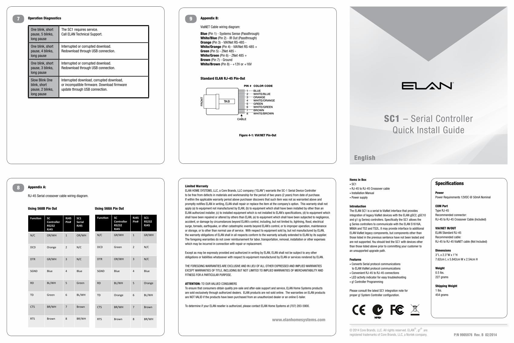
7 9Operation Diagnostics Appendix B:
ViaNET Cable wiring diagram:
Blue (Pin 1) - System Sense (Passthrough)White/Blue (Pin 2) - IR Out (Passthrough)Orange (Pin 3) - VIA!Net RS-485 - White/Orange (Pin 4) - VIA!Net RS-485 +Green (Pin 5) - ZNet 485 -White/Green (Pin 6) - ZNet 485 +Brown (Pin 7) - GroundWhite/Brown (Pin 8) - +12V or +16V
BLUEWHITE/BLUEORANGEWHITE/ORANGEGREENWHITE/GREENBROWNWHITE/BROWN
12345678
PIN # COLOR CODE
FR
ON
T
CABLE
Standard ELAN RJ-45 Pin-Out
TAB
Figure 4-1: VIA!NET Pin-Out
8 Appendix A:
RJ-45 Serial crossover cable wiring diagram.
Using 568B Pin Out Using 568A Pin Out
One blink, short pause, 5 blinks, long pause
The SC1 requires service.Call ELAN Technical Support.
One blink, short pause, 4 blinks, long pause
Interrupted or corrupted download. Redownload through USB connection.
One blink, short pause, 3 blinks, long pause
Interrupted or corrupted download. Redownload through USB connection.
Slow Blink One blink, short pause, 2 blinks, long pause
Interrupted download, corrupted download, or incompatible firmware. Download firmware update through USB connection.
Blue (Pin 1) - Systems Sense (Passthrough) White/Blue (Pin 2) - IR Out (Passthrough)Orange (Pin 3) - VIA!Net RS-485 -White/Orange (Pin 4) - VIA!Net RS-485 +Green (Pin 5) - ZNet 485 -White/Green (Pin 6) - ZNet 485 +Brown (Pin 7) - GroundWhite/Brown (Pin 8) - +12V or +16V
Func%on SC Controller RS232 RJ45
RJ45 Pin#
SC1 Serial RJ45
N/C OR/WH 1 OR/WH
DCD Orange 2 N/C
DTR GR/WH 3 N/C
SGND Blue 4 Blue
RD BL/WH 5 Green
TD Green 6 BL/WH
CTS BR/WH 7 Brown
RTS Brown 8 BR/WH
Func%on SC Controller RS232 RJ45
RJ45 Pin#
SC1 RS232 RJ45
N/C GR/WH 1 GR/WH
DCD Green 2 N/C
DTR OR/WH 3 N/C
SGND Blue 4 Blue
RD BL/WH 5 Orange
TD Orange 6 BL/WH
CTS BR/WH 7 Brown
RTS Brown 8 BR/WH
Standard ELAN RJ-45 Pin-Out
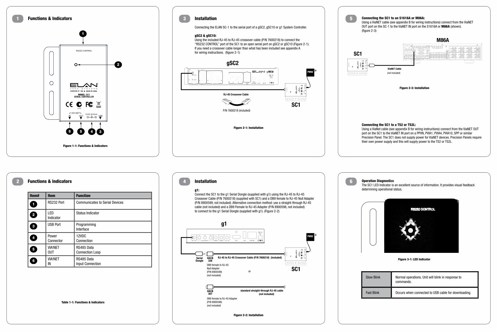
Functions & Indicators
Functions & Indicators2
1 3
4
5
6
1
56 4 3
2
RJ-45 Crossover Cable
SC1
PWR3
gSC2
RJ-45 to RJ-45 Crossover Cable (P/N 7600218) (included)HACB328
SerialDongle
SC1
PWR3
standard straight-through RJ-45 cable (not included)
HACB307
g1
DB9 female to RJ-45 Null Adapter(P/N 8900599)(not included)
DB9 female to RJ-45 Adapter (P/N 8900598) (not included)
RJ-45 to RJ-45 Crossover Cable (P/N 7600218) (included)HACB328
SerialDongle
SC1
PWR3
standard straight-through RJ-45 cable (not included)
HACB307
g1
DB9 female to RJ-45 Null Adapter(P/N 8900599)(not included)
DB9 female to RJ-45 Adapter (P/N 8900598) (not included)
Figure 1-1: Functions & Indicators
Table 1-1: Functions & Indicators
Figure 2-1: Installation
P/N 7600218 (included)
Figure 2-2: Installation
Figure 2-3: Installation
Item# Item Function
1 RS232 Port Communicates to Serial Devices
2 LED Indicator
Status Indicator
3 USB Port Programming Interface
4 Power Connector
12VDC Connection
5 VIA!NETOUT
RS485 DataConnection Loop
6 VIA!NETIN
RS485 DataInput Connection
Installation
Connecting the ELAN SC-1 to the serial port of a gSC2, gSC10 or g1 System Controller.
gSC2 & gSC10:Using the included RJ-45 to RJ-45 crossover cable (P/N 7600218) to connect the “RS232 CONTROL” port of the SC1 to an open serial port on gSC2 or gSC10 (Figure 2-1). If you need a crossover cable longer than what has been included see appendix A for wiring instructions. (figure 2-1)
Installation
g1:Connect the SC1 to the g1 Serial Dongle (supplied with g1) using the RJ-45 to RJ-45 Crossover Cable (P/N 7600218) (supplied with SC1) and a DB9 female to RJ-45 Null Adapter (P/N 8900599, not included). Alternative connection method: use a straight-through RJ-45 cable (not included) and a DB9 Female to RJ-45 Adapter (P/N 8900598, not included) to connect to the g1 Serial Dongle (supplied with g1). (Figure 2-2)
Connecting the SC1 to an S1616A or M86A:Using a ViaNET cable (see appendix B for wiring instructions) connect from the ViaNET OUT port on the SC-1 to the ViaNET IN port on the S1616A or M86A (shown). (figure 2-3)
Operation DiagnosticsThe SC1 LED Indicator is an excellent source of information. It provides visual feedback determining operational status.
Connecting the SC1 to a TS2 or TS2L:Using a ViaNet cable (see appendix B for wiring instructions) connect from the ViaNET OUT port on the SC1 to the ViaNET IN port on a PPVN, PVIA1, PVIA4, PVIA10, SPP or similar Precision Panel. The SC1 does not supply power for ViaNET devices. Precision Panels require their own power supply and this will supply power to the TS2 or TS2L.
Figure 3-1: LED Indicator
ViaNET Cable
SC1
M86A
OUT
INIR LOOP
IN
L+ GND R+
ZONE 4 ZONE 5 ZONE 6 VIANET OUT
ZONE 1 ZONE 2 ZONE 3 VIANET IN
ZONE 1
L+ GND R+
ZONE 2
L+ GND R+
ZONE 3CLASS 2 WIRING - SPEAKER OUTPUTS - 30W/CH. @ 8 ohms
2 3 4 5 6 7
L+ GND R+
ZONE 4
L+ GND R+
ZONE 5
L+ GND R+
ZONE 6
OUT
SOURCE IR OUTPUTS
1 2 3 4 5 6
SENSE INPUTS
ZONE PRE-AMP OUTPUTS
L
L R
IR EXPANSION POR TS
PG/DB OUT
MOH OUT
PG/DB IN
L R
L R
L R
L R
L
R
L
R
L
R
L
R
L
R
1 2 3 4 5 6
81
120VAC 50/60Hz400W
LOOPOUTPUT 5
LOOPOUTPUT 1
SOURCEINPUT 5
SOURCEINPUT 2
LOOPOUTPUT 8
LOOPOUTPUT 7
SOURCEINPUT 6
LOOPOUTPUT 3
LOOPOUTPUT 4
SOURCEINPUT 7
SOURCEINPUT 4
L
L
ALLZONESIR OUT
LOOPOUTPUT 2
R
R
LOOPOUTPUT 6
SOURCEINPUT 8
SOURCEINPUT 3
SOURCEINPUT 1
(not included)
Slow Blink Normal operations. Unit will blink in response to commands.
Fast Blink Occurs when connected to USB cable for downloading.
or