assembly manual - nautilusdownload.nautilus.com/supportdocs/am/bowflex/bfx_pr3000_am_we… ·...
TRANSCRIPT
Nautilus® Bowflex® Schwinn® Fitness StairMaster® Universal® Nautilus Institute®
Assembly Manual
PR3000 Home Gym
001-7279-063008A
® ®
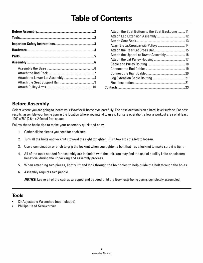
Table of Contents
Before Assembly...................................................................... 2
Tools ........................................................................................... 2
Important Safety Instructions ................................................ 3
Hardware .................................................................................. 4
Parts ........................................................................................... 5
Assembly ................................................................................... 6
Assemble the Base .......................................................... 6 Attach the Rod Pack ........................................................ 7 Attach the Lower Lat Assembly ..................................... 8 Attach the Seat Support Rail .......................................... 9 Attach Pulley Arms ......................................................... 10
Attach the Seat Bottom to the Seat Backbone ......... 11 Attach Leg Extension Assembly ................................... 12 Attach Seat Back ............................................................ 13 Attach the Lat Crossbar with Pulleys ...........................................14 Attach the Rear Lat Cross Bar ...................................... 15 Attach the Upper Lat Tower Assembly ....................... 16 Attach the Lat Pulley Housing ...................................... 17 Cable and Pulley Routing .............................................. 18 Connect the Rod Cables ................................................ 19 Connect the Right Cable ................................................ 20 Leg Extension Cable Routing ........................................ 21 Final Inspection ............................................................... 21Contacts................................................................................... 23
Before AssemblySelect where you are going to locate your Bowflex® home gym carefully. The best location is on a hard, level surface. For best results, assemble your home gym in the location where you intend to use it. For safe operation, allow a workout area of at least 100” x 78” (2.6m x 2.0m) of free space.
Follow these basic tips to make your assembly quick and easy.
1. Gather all the pieces you need for each step.
2. Turn all the bolts and locknuts toward the right to tighten. Turn towards the left to loosen.
3. Use a combination wrench to grip the locknut when you tighten a bolt that has a locknut to make sure it is tight.
4. All of the tools needed for assembly are included with the unit. You may find the use of a utility knife or scissors beneficial during the unpacking and assembly process.
5. When attaching two pieces, lightly lift and look through the bolt holes to help guide the bolt through the holes.
6. Assembly requires two people.
NOTICE: Leave all of the cables wrapped and bagged until the Bowflex® home gym is completely assembled.
Tools• (2)AdjustableWrenches(notincluded)• Phillips Head Screwdriver
Assembly Manual2

Important Safety Instructions
• Keepbystandersandchildrenawayfromtheproductyouareassemblingatalltimes.
• Donotassembleequipmentinawetordamplocation.
• Makesureassemblyisdoneinanappropriateworkspaceawayfromfoottrafficandexposuretobystanders.
• Somecomponentsofthemachinecanbeheavyorawkward.Useasecondpersonwhendoingtheassembly stepsinvolvingtheseparts.Donotdostepsthatinvolveheavyliftingorawkwardmovementsonyourown.
• Donottrytochangethedesignorfunctionalityofthismachine.Thiscouldcompromisethesafetyandcanvoid the warranty.
• If replacement parts are necessary use only genuine Nautilus® replacement parts and hardware. Failure to use genuine replacement parts can cause a risk to users, keep the machine from operating correctly or void the warranty.
• Donotuseorputthemachineintoserviceuntilthemachinehasbeenfullyassembledandinspectedfor correct performance in accordance with the Owner’s Manual.
Thisiconmeansapotentiallyhazardoussituationwhich,ifnotavoided,couldresultindeathorseriousinjury.
Read and understand all warnings on this machine. Carefully read and understand the Assembly Manual.
Before using this equipment, obey the following warnings
Assembly Manual3

Hardware(Hardware not actual size)
Qty. 19 Item #13/8”x 3/4” Hex Head Bolt
Qty. 6Item #10Snap Hook
Qty. 2 Item #25/16”x 2 1/2” Hex Head Bolt
Qty. 2 Item #111/2” x 9 1/2” Threaded Stud
Qty. 3Item #31/4” Washer
Qty. 4Item #12Ball Stop
Qty. 4Item #41/2” Washer
Qty. 2Item #133/8” x 3” Hex Head Bolt
Qty. 31Item #53/8” Washer
Qty. 2 Item #141/2” x 5 1/4” Hex Head Bolt
Qty. 3 Item #6#10 x 1” Phillips Head Screw
Qty. 4 Item #155/16” x 3/4” Hex Head Bolt
Qty. 6Item #73/8” Nylock Nut
Qty. 4 Item #163/8” x 2 3/4” Hex Head Bolt
Qty. 4Item #81/2” Wide Washer
Qty. 6Item #175/16” Washer
Qty. 6Item #91/2” Nylock Nut
Qty. 1Item #18Seat Pin
Assembly Manual4

Parts
19 1 Base Platform20 1 Right Frame Rail21 1 Left Frame Rail22 1 Rear Cross Bar23 1 Central Support24 1 Lat Cross Bar with Pulleys25 1 Rear Lat Cross Bar26 1 Upper Lat Tower27 1 Right Pulley Arm28 1 Left Pulley Arm29 1 Rod Pack30 1 Lower Lat Tower31 1 Seat Back32 1 Seat Backbone33 1 Seat Bottom34 1 Seat Support Rail35 2 Floating Pulleys
36 1 Lat Pulley Housing37 1 Leg Extension Assembly38 2 Roller Tubes39 4 Foam Roller Pads40 1 Placard41 1 Rod Pack Strap42 2 AdjustableHandgrips43 2 Handgrips44 1 Accessory Bag #145 2 Leg Press Extension Cables46 1 Snap Hook47 1 Accessory Bag #248 4 Roller End Caps49 1 Leg Extension Lock Pin50 1 Seat Backbone Lock Pin51 1 Hardware Bag52 1 ManualKit
Item # Item #Qty. Qty.Description Description
19
20
21
22
23
24
2526
27
28
29
30
31
32
3334
35
36
37
38
39
40
41 42 4344
45
46
47
48
49
50
5152
Assembly Manual5

Assembly
Step 1: Assemble the Base Parts• BasePlatform(#19)• RightFrameRail(#20)• LeftFrameRail(#21)• RearCrossBar(#22)• CentralSupport(#23)
Hardware• (4)3/8”x3/4”HexHeadBolts(#1)• (4)3/8”x23/4”HexHeadBolts(#16)• (12)3/8”Washers(#5)• (4)3/8”NylockNuts(#7)
Tools• AdjustableWrench(notincluded)
1-1 Put the Base Assembly parts on the floor.
1-2 Align the bolt holes on the Right and Left Frame Rails with the holes in the Base Platform, Rear Cross Bar and the Central Support.
1-3 Install the hardware, but do not tighten the bolts.
1-4 Tighten all hardware.
20
21
22
19
5
16
23
1
7
Assembly Manual6
Assembly
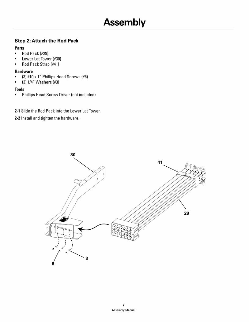
Step 2: Attach the Rod PackParts• RodPack(#29)• LowerLatTower(#30)• RodPackStrap(#41)
Hardware• (3)#10x1”PhillipsHeadScrews(#6)• (3)1/4”Washers(#3)
Tools• PhillipsHeadScrewDriver(notincluded)
2-1 Slide the Rod Pack into the Lower Lat Tower.
2-2 Install and tighten the hardware.
30
29
41
36
Assembly Manual7

Assembly
Step 3: Attach the Lower Lat Assembly to the Base AssemblyParts• CompetedAssembly(fromstep1)• LowerLatTowerAssembly(fromstep2)
Hardware• (2)3/8”x3/4”HexHeadBolts(#1)• (2)3/8”Washers(#5)
Tools• AdjustableWrench(notincluded)
3-1 Put the Lower Lat Tower Assembly onto the Completed Assembly.
3-2 Install and tighten the hardware.
5
1
Assembly Manual8
Assembly
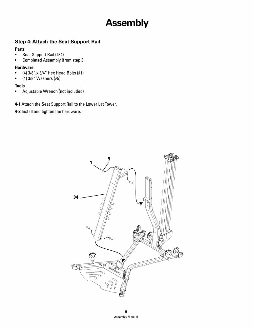
Step 4: Attach the Seat Support RailParts• SeatSupportRail(#34)• CompletedAssembly(fromstep3)
Hardware• (4)3/8”x3/4”HexHeadBolts(#1)• (4)3/8”Washers(#5)
Tools• AdjustableWrench(notincluded)
4-1 Attach the Seat Support Rail to the Lower Lat Tower.
4-2 Install and tighten the hardware.
51
34
Assembly Manual9

Assembly
Step 5: Attach the Pulley ArmsParts• RightPulleyArm(#27)• LeftPulleyArm(#28)• CompletedAssembly(fromstep4)
Hardware• (4)3/8”x3/4”HexHeadBolts(#1)• (4)3/8”Washers(#5)• (2)1/2”x91/2”ThreadedStuds(#11)• (4)1/2”WideWashers(#8)• (4)1/2”NylockNuts(#9)
Tools• (2)AdjustableWrenches(notincluded)
5-1 Attach the the Right and Left Pulley Arms to the Completed Assembly.
5-2 Install and tighten the hardware.
51
9
8
9
11
8
27
28
Assembly Manual10

Assembly
Step 6: Attach the Seat Bottom to the Seat BackboneParts• SeatBottom(#33)• SeatBackbone(#32)
Hardware• (4)5/16”x3/4”HexHeadBolts(#15)• (4)5/16”Washers(#17)
Tools• AdjustableWrench(notincluded)
6-1 Attach the Seat Bottom to the Seat Backbone.
6-2 Install and tighten the hardware.
33
32
17
15
Assembly Manual11

Assembly
Step 7: Attach the Leg Extension AssemblyParts• LegExtensionAssembly(#37)• LegExtensionLockPin(#49)• SeatBottomAssembly(fromstep6)
7-1 Attach the Leg Extension Assembly to the Seat Bottom Assembly with the Leg Extension Lock Pin.
37
49
Assembly Manual12

Assembly
Step 8: Attach the Seat BackParts• SeatBack(#31)• CompletedAssembly(fromstep5)
Hardware• (2)5/16”x21/2”HexHeadBolts(#2)• (2)5/16”Washers(#17)
Tools• AdjustableWrench(notincluded)
8-1 Attach the Seat back to the Seat Support Rail.
8-2 Install and tighten the hardware.
3117
2
Assembly Manual13

Assembly
Step 9: Attach the Lat Crossbar with Pulleys to the Upper Lat TowerParts• LatCrossbarwithPulleys(#24)• UpperLatTower(#26)
Hardware• (2)3/8”x3”HexHeadBolts(#13)• (4)3/8”Washers(#5)• (2)3/8”NylockNuts(#7)
Tools• (2)AdjustableWrenches(notincluded)
9-1 Attach the Lat Crossbar with Pulleys to the Upper Lat Tower.
9-2 Install and tighten the hardware.
7
5
13
26
24
Assembly Manual14
Assembly
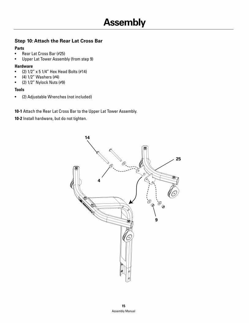
Step 10: Attach the Rear Lat Cross BarParts• RearLatCrossBar(#25)• UpperLatTowerAssembly(fromstep9)
Hardware• (2)1/2”x51/4”HexHeadBolts(#14)• (4)1/2”Washers(#4)• (2)1/2”NylockNuts(#9)
Tools
• (2)AdjustableWrenches(notincluded)
10-1 Attach the Rear Lat Cross Bar to the Upper Lat Tower Assembly.
10-2 Install hardware, but do not tighten.
25
14
4
9
Assembly Manual15
Assembly
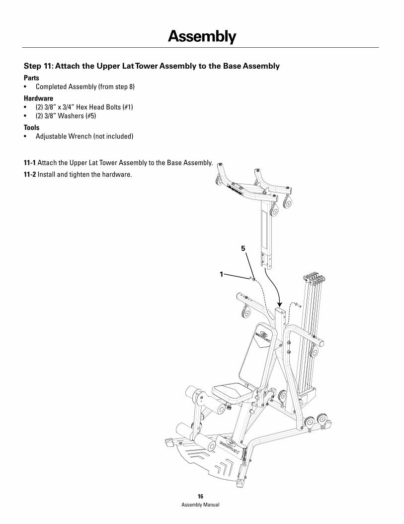
Step 11: Attach the Upper Lat Tower Assembly to the Base AssemblyParts• CompletedAssembly(fromstep8)
Hardware• (2)3/8”x3/4”HexHeadBolts(#1)• (2)3/8”Washers(#5)
Tools• AdjustableWrench(notincluded)
11-1 Attach the Upper Lat Tower Assembly to the Base Assembly.
11-2 Install and tighten the hardware.
5
1
Assembly Manual16

Assembly
Step 12: Attach the Lat Pulley HousingParts• LatPulleyHousing(#36)• CompletedAssembly(fromstep11)
Hardware• (3)3/8”x3/4”HexHeadBolts(#1)• (3)3/8”Washers(#5)
Tools• AdjustableWrench(notincluded)
12-1 Attach the Lat Pulley Housing to the Lat Tower.
Note: Rod Pack removed from illustration for clarity.
1
1
36
5
Assembly Manual17

Assembly
Step 13: Cable and Pulley Routing the Rear PulleysParts• CompletedAssembly(fromstep12)Tools• AdjustableWrench(notincluded)
13-1 Remove the 3/8” x 4 1/2” Hex Head Bolt and the 3/8” Washer in the center of the Lat Pulley Housing.
13-2 Remove the two pulley wheels from the Lat Pulley Housing.
13-3 Unwrap the Right Pulley Cable from the Right Frame Rail and thread it under and then over one of the pulley wheels. Pinch the Right Pulley Cable to the pulley wheel until installed.
13-4 Unwrap the Left Pulley Cable on the Left Frame Rail and thread it under and then over the other pulley wheel.
13-5 Put the pulleys with the cables wrapped around them back into the Lat Pulley Housing.
13-6 Replace and tighten the 3/8” x 4 1/2” Hex Head Bolt and the 3/8” Washer in the center of the Lat Pulley Housing.
Assembly Manual18

Assembly
Step 14: Connect the Rod Cables through the Right Floating and Lat Tower Pulleys
14-1 Put the right cable that runs through the Lat Pulley Housing through the Floating Pulley (A).
14-2 Pull the same cable through the Pulley on the Rear Lat Cross Bar (B) and then through the Pulley on the Front Lat Cross Bar (C).
14-3PutthecableendthroughtheCableEndBallStop(D).
14-4 Attach the Cable Core (E) to keep the cable from falling out of the pulleys.
14-5 Repeat steps 14-1 through 14-4 on the opposite side.
A
C
B
D
E
Assembly Manual19
Assembly
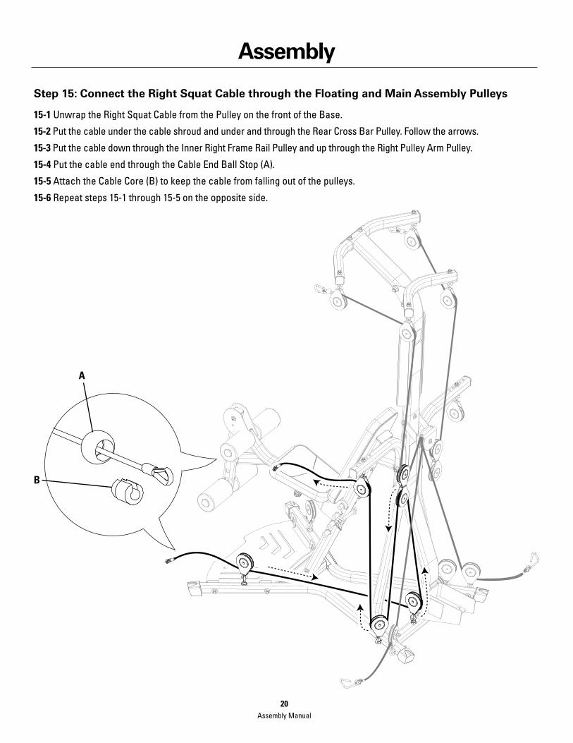
Step 15: Connect the Right Squat Cable through the Floating and Main Assembly Pulleys
15-1 Unwrap the Right Squat Cable from the Pulley on the front of the Base.
15-2 Put the cable under the cable shroud and under and through the Rear Cross Bar Pulley. Follow the arrows.
15-3 Put the cable down through the Inner Right Frame Rail Pulley and up through the Right Pulley Arm Pulley.
15-4 Put the cable end through the Cable End Ball Stop (A).
15-5 Attach the Cable Core (B) to keep the cable from falling out of the pulleys.
15-6 Repeat steps 15-1 through 15-5 on the opposite side.
A
B
Assembly Manual20
45
46
46
Assembly
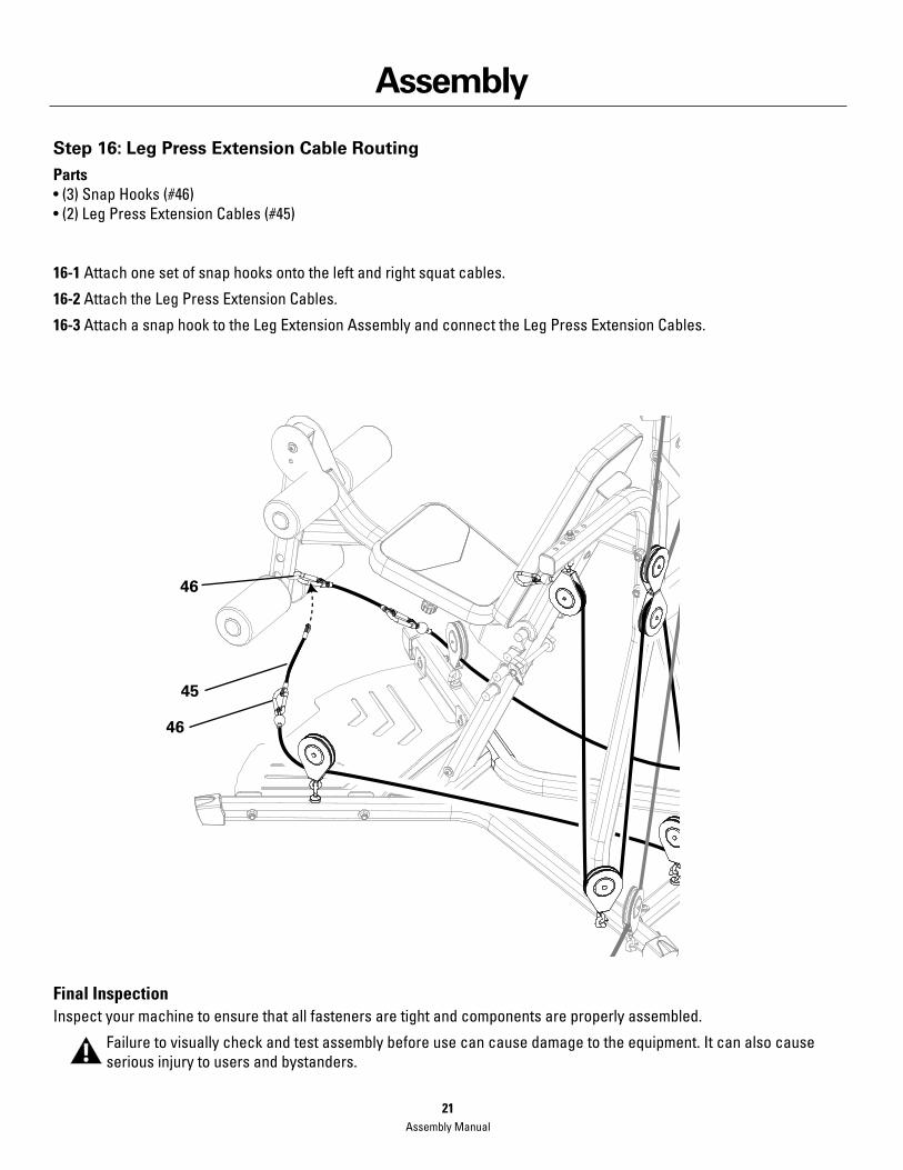
Step 16: Leg Press Extension Cable RoutingParts•(3)SnapHooks(#46)•(2)LegPressExtensionCables(#45)
16-1 Attach one set of snap hooks onto the left and right squat cables.
16-2 Attach the Leg Press Extension Cables.
16-3 Attach a snap hook to the Leg Extension Assembly and connect the Leg Press Extension Cables.
Final InspectionInspect your machine to ensure that all fasteners are tight and components are properly assembled.
Failure to visually check and test assembly before use can cause damage to the equipment. It can also cause seriousinjurytousersandbystanders.
Assembly Manual21

Assembly Manual22
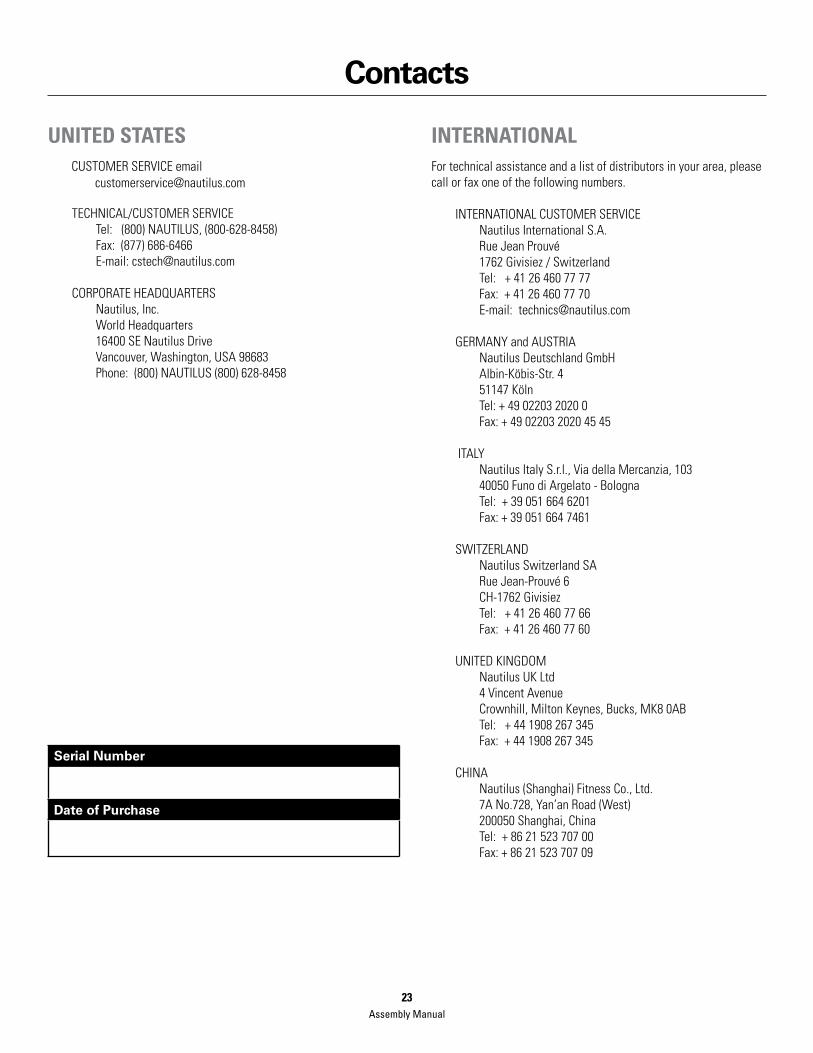
Contacts
UNITED STATES CUSTOMER SERVICE email [email protected]
TECHNICAL/CUSTOMER SERVICETel: (800) NAUTILUS, (800-628-8458)Fax: (877) 686-6466E-mail: [email protected]
CORPORATE HEADQUARTERSNautilus, Inc.World Headquarters16400 SE Nautilus DriveVancouver, Washington, USA 98683Phone: (800) NAUTILUS (800) 628-8458
INTERNATIONALFor technical assistance and a list of distributors in your area, please call or fax one of the following numbers.
INTERNATIONAL CUSTOMER SERVICE Nautilus International S.A.Rue Jean Prouvé1762 Givisiez / SwitzerlandTel: + 41 26 460 77 77Fax: + 41 26 460 77 70E-mail: [email protected]
GERMANY and AUSTRIA Nautilus Deutschland GmbH Albin-Köbis-Str. 4 51147 Köln Tel: + 49 02203 2020 0 Fax: + 49 02203 2020 45 45
ITALY Nautilus Italy S.r.l., Via della Mercanzia, 10340050 Funo di Argelato - BolognaTel: + 39 051 664 6201Fax: + 39 051 664 7461
SWITZERLANDNautilus Switzerland SARue Jean-Prouvé 6 CH-1762 GivisiezTel: + 41 26 460 77 66Fax: + 41 26 460 77 60
UNITED KINGDOMNautilus UK Ltd4 Vincent AvenueCrownhill, Milton Keynes, Bucks, MK8 0ABTel: + 44 1908 267 345Fax: + 44 1908 267 345
CHINANautilus (Shanghai) Fitness Co., Ltd.7A No.728, Yan’an Road (West)200050 Shanghai, China Tel: + 86 21 523 707 00Fax: + 86 21 523 707 09
Serial Number
Date of Purchase
Assembly Manual23

©2008. Nautilus, Inc. All rights reserved. Nautilus, the Nautilus Logo, Universal, the Universal Logo, Bowflex, the Bowflex logo, Power Rod, StairMaster and Nautilus Institute are either regis-tered trademarks or trademarks of Nautilus, Inc. Schwinn is a registered trademark. All other trademarks are owned by their respective companies. Nautilus, Inc., World Headquarters, 16400 SE NautilusDrive,Vancouver,WA986831-800-NAUTILUSwww.nautilus.com
Nautilus® Bowflex® Schwinn® Fitness StairMaster® Universal® Nautilus Institute®
Printed in China