gmv configurator training guide v1 -...
TRANSCRIPT
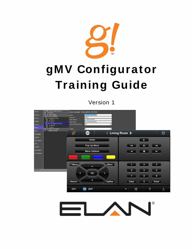
gMV Configurator Training Guide
Version 1
Copyright Copyright © ELAN Home Systems, LLC. All Rights Reserved.
All brand or product names used in this document are trademarks, registered trademarks, trade names, or service marks of their respective holders.
Material in this document is subject to change without notice: contact ELAN if you would like to confirm that you have the most recent version. ELAN Home Systems, LLC. CORE Brands 1800 S. McDowell Blvd Petaluma, CA. 94954
Document Revision: 2/27/2015
Contents Lesson 1: gMV Setup ............................................................. 1-1
Exercise 1: Add gMV Comm Device .............................................................. 1-3 Lesson 2: gMV Adding Sources .............................................. 2-1
Exercise 1: Adding Sources to the gMV ......................................................... 2-2 Exercise 2: Configuring the Audio Input Type ................................................ 2-6 Exercise 3: Assigning the Inputs & DSP Mix .................................................. 2-9 Exercise 4: Adjusting Input Level Gain & Lip Sync Delay ............................ 2-11 Exercise 5: Assigning the EDID for a Source ............................................... 2-12 Exercise 6: Adding an additional Source ..................................................... 2-13
Lesson 3: gMV Adding Zones ................................................. 3-1
Exercise 1: Zone Name ................................................................................. 3-2 Exercise 2: gMV Zone Configuration ............................................................. 3-3 Exercise 3: gMV Zone Turn On Settings ........................................................ 3-9 Exercise 4: gMV Zone Audio Settings .......................................................... 3-11 Exercise 5: gMV Zone Feature Settings ...................................................... 3-13 Exercise 6: gMV EQ Settings & Zone Settings Page ................................... 3-15 Exercise 7: Display Setup ............................................................................ 3-19
Lesson 4: gMV in the g!Viewer .............................................. 4-1
Exercise 1: Adding Zones to the Viewer ........................................................ 4-2 Exercise 2: Check the Viewer ........................................................................ 4-4
Lesson 5: gMV Commissioning .............................................. 5-1
Exercise 1: Commissioning ............................................................................ 5-2 Exercise 2: Replacing an HDMI Device ......................................................... 5-3 Exercise 3: Factory Reset gMV ...................................................................... 5-4

Your Resources at ELAN In addition to the information in this Training Guide, be sure to check out ELAN’s website at www.elanhomesystems.com. The website provides access to a wealth of documentation including Integration Notes for detailed information on specific systems with which the g! Software integrates. Our Technical Support staff can assist you Monday through Friday from 9:00 a.m. to 7:00 p.m. EST and 6:00 a.m.to 4 p.m. Pacific at 800-622-3526. Email: [email protected]
Lesson 1 gMV Set Up
Overview
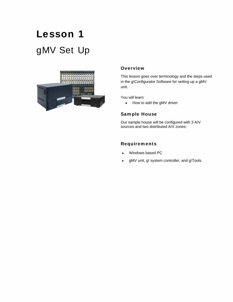
This lesson goes over terminology and the steps used in the g!Configurator Software for setting up a gMV unit. You will learn:
How to add the gMV driver.
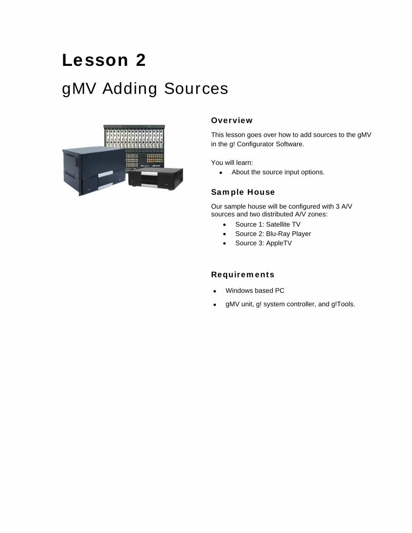
Sample House
Our sample house will be configured with 3 A/V sources and two distributed A/V zones:
Requirements
Windows based PC
gMV unit, g! system controller, and g!Tools.
gMV Set Up 2
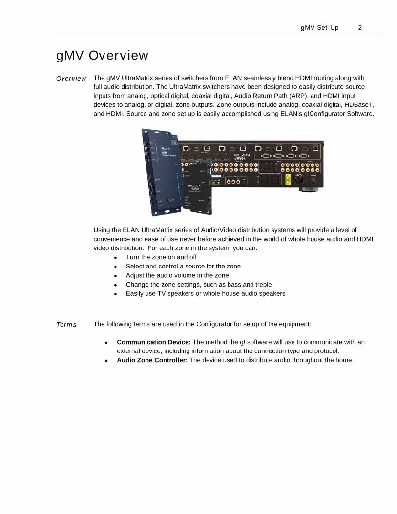
0BgMV Overview Overview The gMV UltraMatrix series of switchers from ELAN seamlessly blend HDMI routing along with
full audio distribution. The UltraMatrix switchers have been designed to easily distribute source inputs from analog, optical digital, coaxial digital, Audio Return Path (ARP), and HDMI input devices to analog, or digital, zone outputs. Zone outputs include analog, coaxial digital, HDBaseT, and HDMI. Source and zone set up is easily accomplished using ELAN’s g!Configurator Software.
Using the ELAN UltraMatrix series of Audio/Video distribution systems will provide a level of convenience and ease of use never before achieved in the world of whole house audio and HDMI video distribution. For each zone in the system, you can:
Turn the zone on and off
Select and control a source for the zone
Adjust the audio volume in the zone
Change the zone settings, such as bass and treble
Easily use TV speakers or whole house audio speakers
Terms The following terms are used in the Configurator for setup of the equipment:
Communication Device: The method the g! software will use to communicate with an external device, including information about the connection type and protocol.
Audio Zone Controller: The device used to distribute audio throughout the home.
gMV Set Up 3
Exercise 1: Add gMV Comm Device
Overview When using the gMV units there are two control options, RS-232 and Ethernet. When controlling the gMV unit using RS-232 a communication device is needed to bridge the gMV Zone Controller to the gSC system controller. Exercise 1 will guide you through how to add communication device for the gMV unit and how to add the gMV as a zone controller. We will use the gMV64 for this lesson.
Note: When controlling the gMV unit using Ethernet no communication device is needed and this
step maybe skipped.
How-to 1. Add the communication device.
a. Start the Configurator, click the Media tab, and then right-click Communication
Devices.
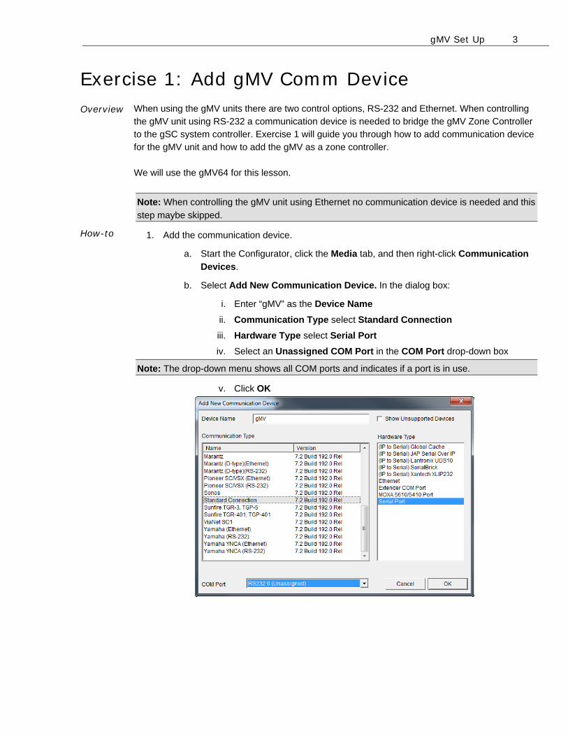
b. Select Add New Communication Device. In the dialog box:
i. Enter “gMV” as the Device Name
ii. Communication Type select Standard Connection
iii. Hardware Type select Serial Port
iv. Select an Unassigned COM Port in the COM Port drop-down box
Note: The drop-down menu shows all COM ports and indicates if a port is in use.
v. Click OK
gMV Set Up 4
Quick Reference: Add New Communication Device
Device Name Enter a name for the external device. This can be any name, but should be descriptive so that you can identify this specific device in the Configurator. DO NOT leave this field set to “New Device”.
Show unsupported devices
Select this checkbox to display legacy devices in the Communication Type window. Legacy devices have not been tested with the current version of g! and are no longer supported by ELAN. If you choose to install an unsupported device, a message will display to warn that the device is not supported by ELAN technical support.
Communication Type
This is the protocol of the communication. See the Integration Note for the specific thermostat for more information.
Hardware Type The type of connection you are using, such as serial port or Ethernet.
Device This drop down will populate with the appropriate device for the selected Hardware Type. I.E. When Serial Port Hardware Type is selected the Device dropdown changes to COM Port.
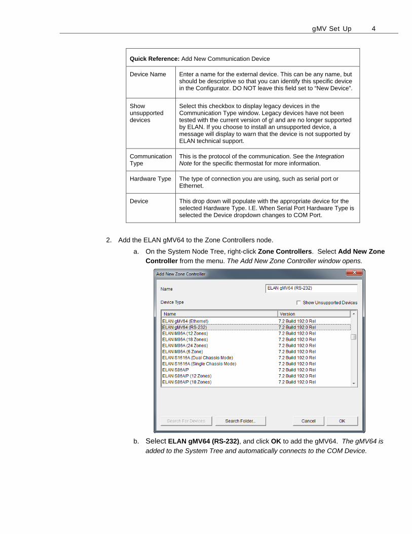
2. Add the ELAN gMV64 to the Zone Controllers node.
a. On the System Node Tree, right-click Zone Controllers. Select Add New Zone
Controller from the menu. The Add New Zone Controller window opens.
b. Select ELAN gMV64 (RS-232), and click OK to add the gMV64. The gMV64 is
added to the System Tree and automatically connects to the COM Device.
gMV Set Up 5
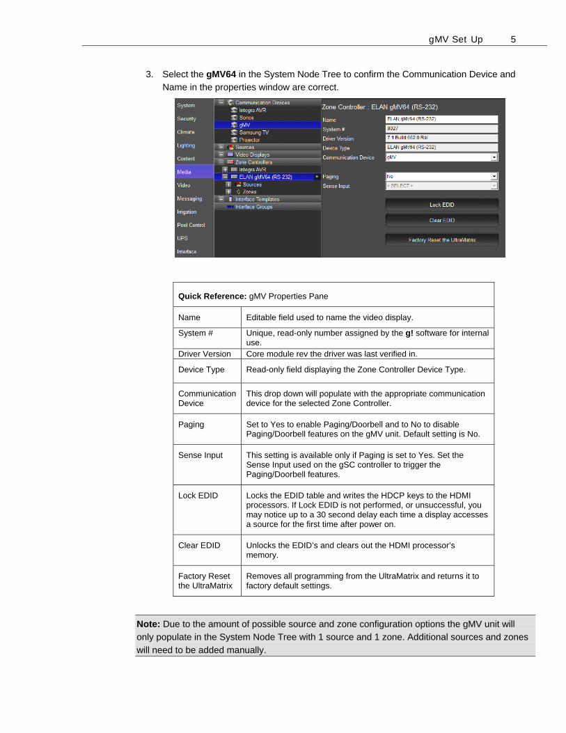
3. Select the gMV64 in the System Node Tree to confirm the Communication Device and
Name in the properties window are correct.
Quick Reference: gMV Properties Pane
Name Editable field used to name the video display.
System # Unique, read-only number assigned by the g! software for internal use.
Driver Version Core module rev the driver was last verified in.
Device Type Read-only field displaying the Zone Controller Device Type.
Communication Device
This drop down will populate with the appropriate communication device for the selected Zone Controller.
Paging Set to Yes to enable Paging/Doorbell and to No to disable Paging/Doorbell features on the gMV unit. Default setting is No.
Sense Input This setting is available only if Paging is set to Yes. Set the Sense Input used on the gSC controller to trigger the Paging/Doorbell features.
Lock EDID Locks the EDID table and writes the HDCP keys to the HDMI processors. If Lock EDID is not performed, or unsuccessful, you may notice up to a 30 second delay each time a display accesses a source for the first time after power on.
Clear EDID Unlocks the EDID’s and clears out the HDMI processor’s memory.
Factory Reset the UltraMatrix
Removes all programming from the UltraMatrix and returns it to factory default settings.
Note: Due to the amount of possible source and zone configuration options the gMV unit will
only populate in the System Node Tree with 1 source and 1 zone. Additional sources and zones
will need to be added manually.

gMV Set Up 6
Notes: _____________________________________________________________________________
_____________________________________________________________________________
_____________________________________________________________________________
_____________________________________________________________________________
_____________________________________________________________________________
_____________________________________________________________________________
_____________________________________________________________________________
_____________________________________________________________________________
_____________________________________________________________________________
_____________________________________________________________________________
_____________________________________________________________________________
_____________________________________________________________________________
_____________________________________________________________________________
_____________________________________________________________________________
_____________________________________________________________________________
_____________________________________________________________________________
_____________________________________________________________________________
_____________________________________________________________________________
_____________________________________________________________________________
_____________________________________________________________________________
_____________________________________________________________________________
_____________________________________________________________________________
_____________________________________________________________________________
_____________________________________________________________________________
_____________________________________________________________________________
_____________________________________________________________________________
_____________________________________________________________________________
_____________________________________________________________________________
_____________________________________________________________________________
_____________________________________________________________________________
Lesson 2 gMV Adding Sources
Overview
This lesson goes over how to add sources to the gMV in the g! Configurator Software. You will learn:
About the source input options.
Sample House
Our sample house will be configured with 3 A/V sources and two distributed A/V zones:
Source 1: Satellite TV Source 2: Blu-Ray Player Source 3: AppleTV
Requirements
Windows based PC
gMV unit, g! system controller, and g!Tools.
gMV Adding Sources 2
Exercise 1: Adding Sources to the gMV Overview In a typical installation, sources are assigned to specific inputs on the zone controller. The g!
software needs to know which sources are assigned to each input so that the correct signals can
be sent to the zone controller based on user input in the Viewer interface. Due to the amount of
possible source configuration options the gMV will only populate in the System Node Tree with 1
source. Additional sources will need to be added manually.
In Lesson 2, you will add sources to the gMV unit. We will begin by adding a DirecTV satellite box
to the gMV Sources node.
Note: This exercise assumes the Satellite TV source is already created. For information on how
to add a source in the Media tab please see the g!Configurator Training Guide, Lesson 6
Distributed A/V Part 1.
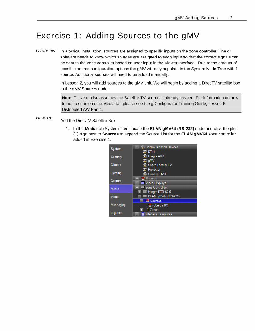
How-to Add the DirecTV Satellite Box
1. In the Media tab System Tree, locate the ELAN gMV64 (RS-232) node and click the plus (+) sign next to Sources to expand the Source List for the ELAN gMV64 zone controller added in Exercise 1.
gMV Adding Sources 3
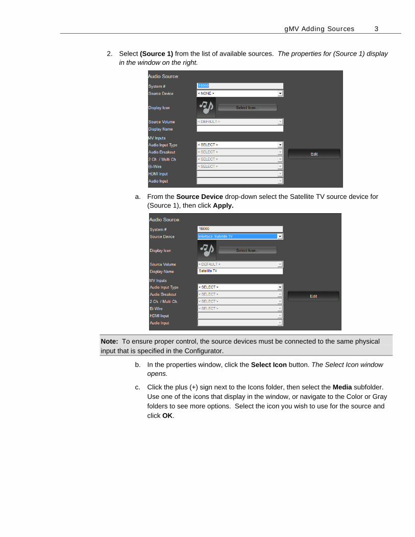
2. Select (Source 1) from the list of available sources. The properties for (Source 1) display in the window on the right.
a. From the Source Device drop-down select the Satellite TV source device for (Source 1), then click Apply.
Note: To ensure proper control, the source devices must be connected to the same physical
input that is specified in the Configurator.
b. In the properties window, click the Select Icon button. The Select Icon window opens.
c. Click the plus (+) sign next to the Icons folder, then select the Media subfolder.
Use one of the icons that display in the window, or navigate to the Color or Gray
folders to see more options. Select the icon you wish to use for the source and
click OK.
gMV Adding Sources 4
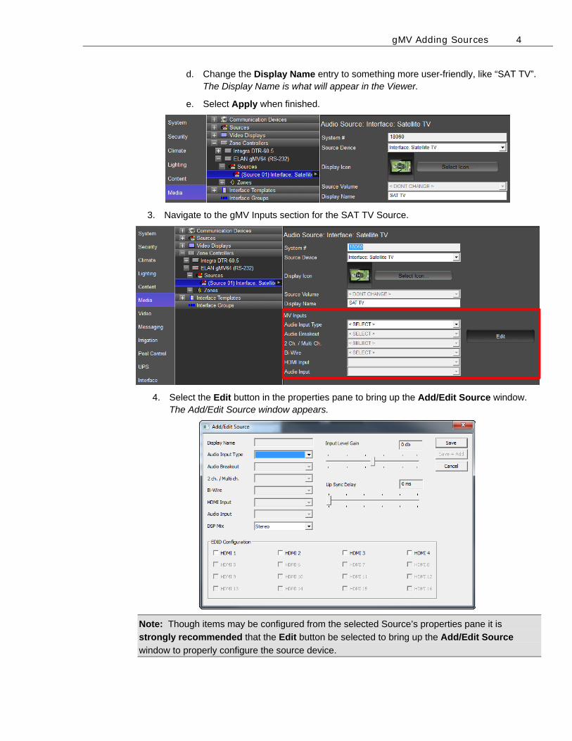
d. Change the Display Name entry to something more user-friendly, like “SAT TV”. The Display Name is what will appear in the Viewer.
e. Select Apply when finished.
3. Navigate to the gMV Inputs section for the SAT TV Source.
4. Select the Edit button in the properties pane to bring up the Add/Edit Source window. The Add/Edit Source window appears.
Note: Though items may be configured from the selected Source’s properties pane it is
strongly recommended that the Edit button be selected to bring up the Add/Edit Source
window to properly configure the source device.
gMV Adding Sources 5
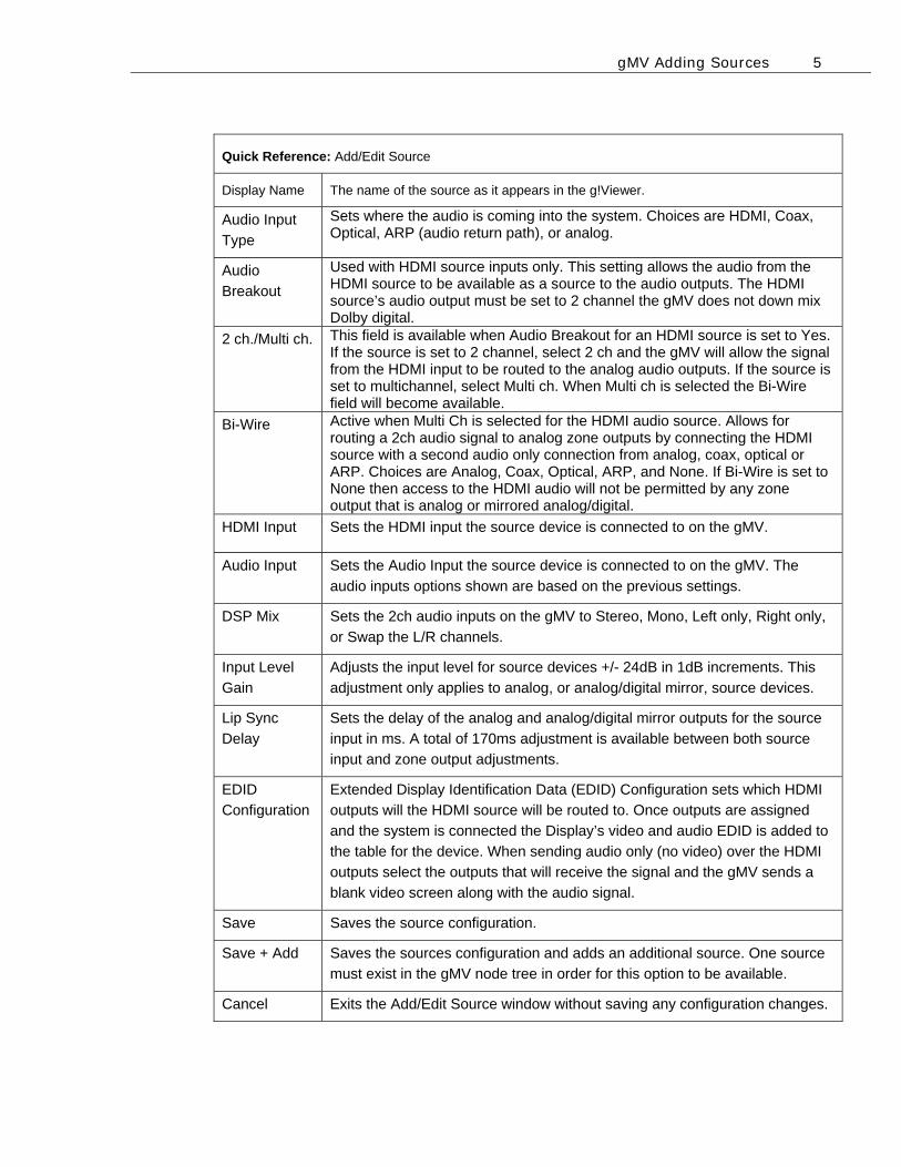
Quick Reference: Add/Edit Source
Display Name The name of the source as it appears in the g!Viewer.
Audio Input
Type
Sets where the audio is coming into the system. Choices are HDMI, Coax, Optical, ARP (audio return path), or analog.
Audio
Breakout
Used with HDMI source inputs only. This setting allows the audio from the HDMI source to be available as a source to the audio outputs. The HDMI source’s audio output must be set to 2 channel the gMV does not down mix Dolby digital.
2 ch./Multi ch. This field is available when Audio Breakout for an HDMI source is set to Yes. If the source is set to 2 channel, select 2 ch and the gMV will allow the signal from the HDMI input to be routed to the analog audio outputs. If the source is set to multichannel, select Multi ch. When Multi ch is selected the Bi-Wire field will become available.
Bi-Wire Active when Multi Ch is selected for the HDMI audio source. Allows for routing a 2ch audio signal to analog zone outputs by connecting the HDMI source with a second audio only connection from analog, coax, optical or ARP. Choices are Analog, Coax, Optical, ARP, and None. If Bi-Wire is set to None then access to the HDMI audio will not be permitted by any zone output that is analog or mirrored analog/digital.
HDMI Input Sets the HDMI input the source device is connected to on the gMV.
Audio Input Sets the Audio Input the source device is connected to on the gMV. The
audio inputs options shown are based on the previous settings.
DSP Mix Sets the 2ch audio inputs on the gMV to Stereo, Mono, Left only, Right only,
or Swap the L/R channels.
Input Level
Gain
Adjusts the input level for source devices +/- 24dB in 1dB increments. This
adjustment only applies to analog, or analog/digital mirror, source devices.
Lip Sync
Delay
Sets the delay of the analog and analog/digital mirror outputs for the source
input in ms. A total of 170ms adjustment is available between both source
input and zone output adjustments.
EDID
Configuration
Extended Display Identification Data (EDID) Configuration sets which HDMI
outputs will the HDMI source will be routed to. Once outputs are assigned
and the system is connected the Display’s video and audio EDID is added to
the table for the device. When sending audio only (no video) over the HDMI
outputs select the outputs that will receive the signal and the gMV sends a
blank video screen along with the audio signal.
Save Saves the source configuration.
Save + Add Saves the sources configuration and adds an additional source. One source
must exist in the gMV node tree in order for this option to be available.
Cancel Exits the Add/Edit Source window without saving any configuration changes.
gMV Adding Sources 6
Exercise 2: Configuring the Audio Input Type Overview How-to
The gMV UltraMatrix features flexibility on the audio inputs that allows for the source’s audio input type to be selected for distribution to analog or digital audio outputs.
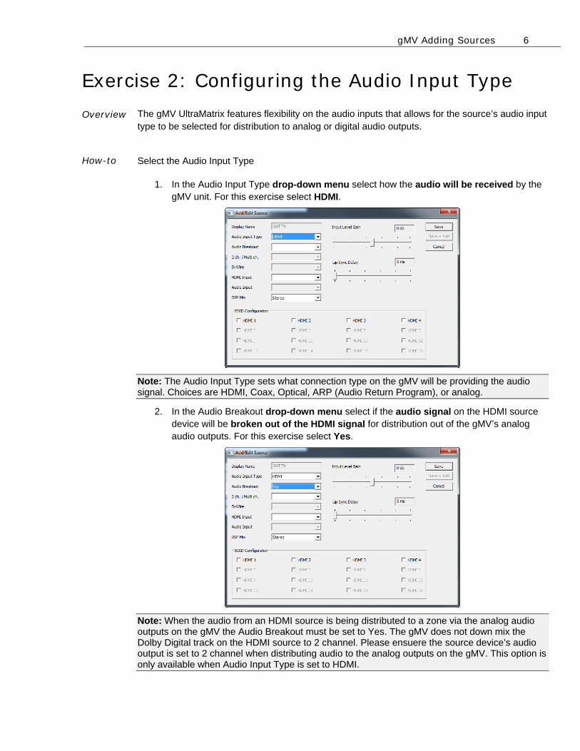
Select the Audio Input Type
1. In the Audio Input Type drop-down menu select how the audio will be received by the gMV unit. For this exercise select HDMI.
Note: The Audio Input Type sets what connection type on the gMV will be providing the audio signal. Choices are HDMI, Coax, Optical, ARP (Audio Return Program), or analog.
2. In the Audio Breakout drop-down menu select if the audio signal on the HDMI source device will be broken out of the HDMI signal for distribution out of the gMV’s analog audio outputs. For this exercise select Yes.
Note: When the audio from an HDMI source is being distributed to a zone via the analog audio outputs on the gMV the Audio Breakout must be set to Yes. The gMV does not down mix the Dolby Digital track on the HDMI source to 2 channel. Please ensuere the source device’s audio output is set to 2 channel when distributing audio to the analog outputs on the gMV. This option is only available when Audio Input Type is set to HDMI.
gMV Adding Sources 7
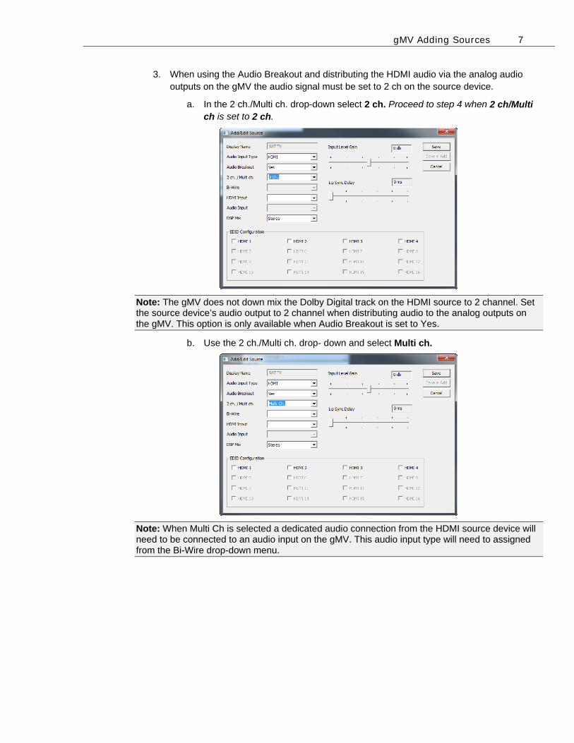
3. When using the Audio Breakout and distributing the HDMI audio via the analog audio outputs on the gMV the audio signal must be set to 2 ch on the source device.
a. In the 2 ch./Multi ch. drop-down select 2 ch. Proceed to step 4 when 2 ch/Multi ch is set to 2 ch.
Note: The gMV does not down mix the Dolby Digital track on the HDMI source to 2 channel. Set the source device’s audio output to 2 channel when distributing audio to the analog outputs on the gMV. This option is only available when Audio Breakout is set to Yes.
b. Use the 2 ch./Multi ch. drop- down and select Multi ch.
Note: When Multi Ch is selected a dedicated audio connection from the HDMI source device will need to be connected to an audio input on the gMV. This audio input type will need to assigned from the Bi-Wire drop-down menu.
gMV Adding Sources 8
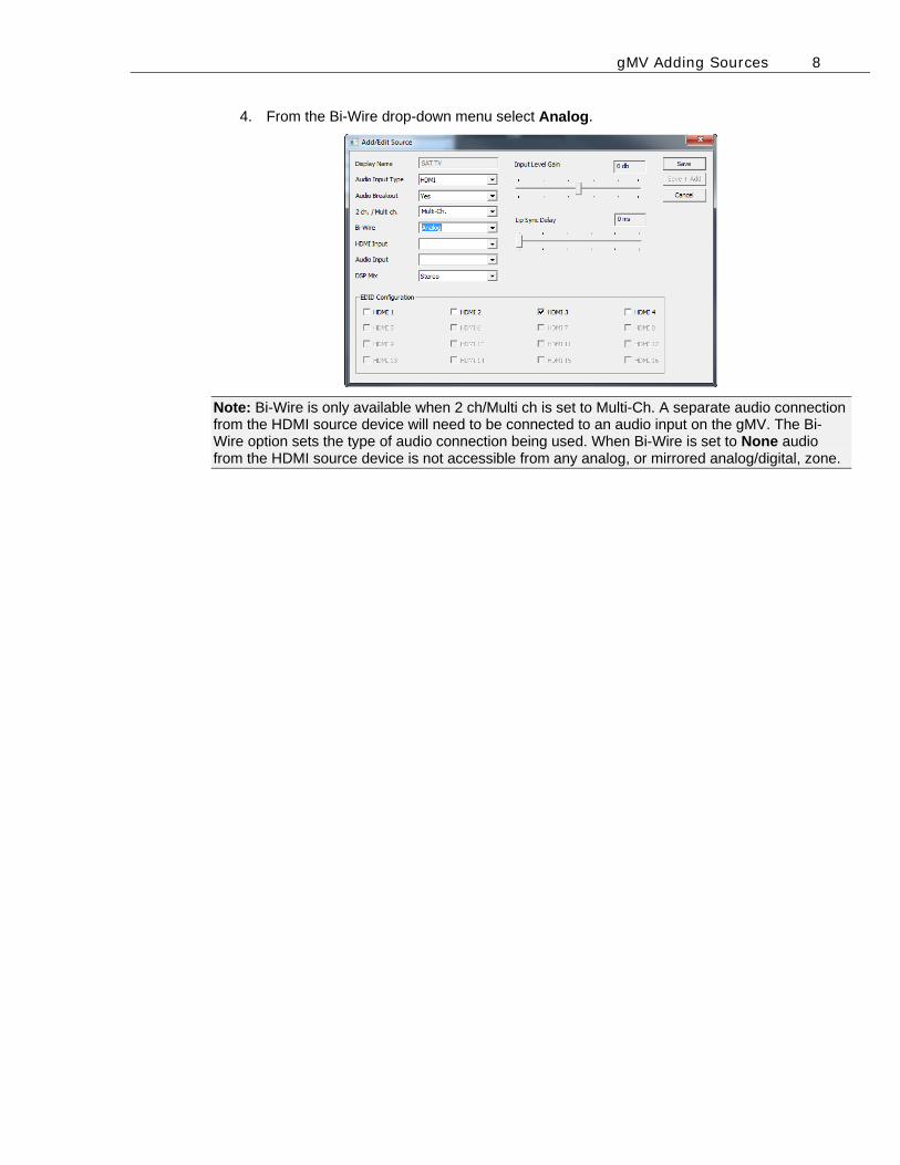
4. From the Bi-Wire drop-down menu select Analog.
Note: Bi-Wire is only available when 2 ch/Multi ch is set to Multi-Ch. A separate audio connection from the HDMI source device will need to be connected to an audio input on the gMV. The Bi-Wire option sets the type of audio connection being used. When Bi-Wire is set to None audio from the HDMI source device is not accessible from any analog, or mirrored analog/digital, zone.
gMV Adding Sources 9
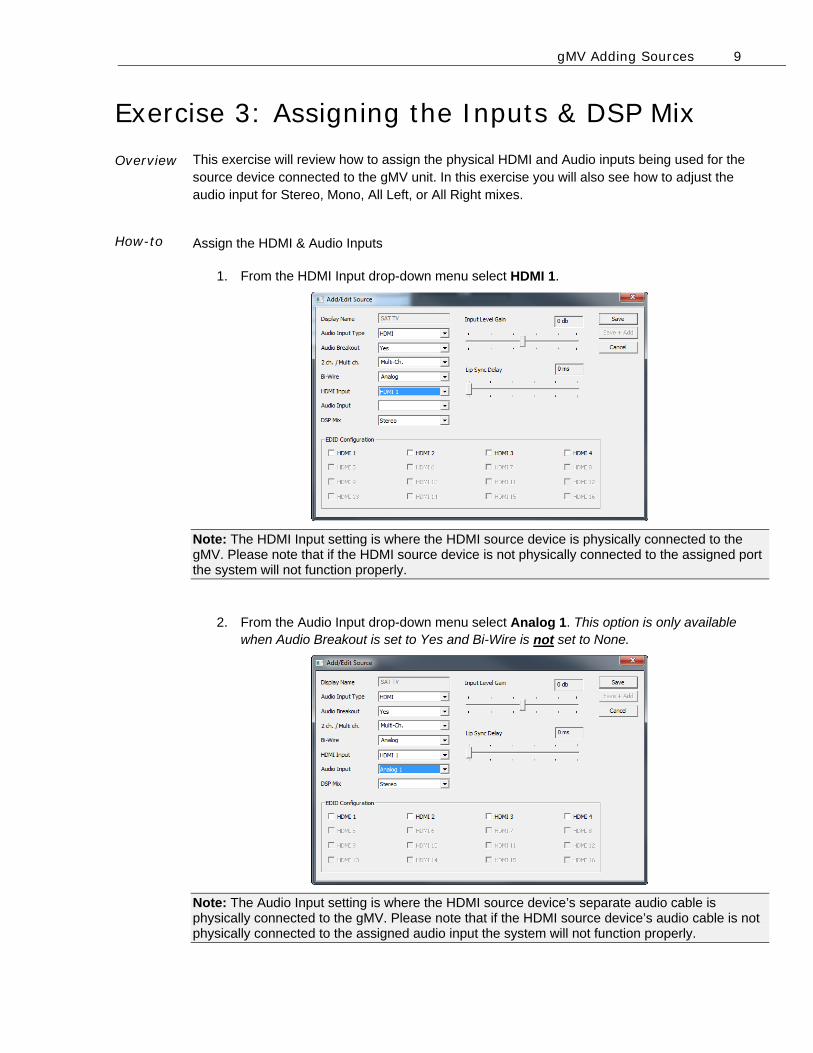
Exercise 3: Assigning the Inputs & DSP Mix Overview How-to
This exercise will review how to assign the physical HDMI and Audio inputs being used for the source device connected to the gMV unit. In this exercise you will also see how to adjust the audio input for Stereo, Mono, All Left, or All Right mixes.
Assign the HDMI & Audio Inputs
1. From the HDMI Input drop-down menu select HDMI 1.
Note: The HDMI Input setting is where the HDMI source device is physically connected to the gMV. Please note that if the HDMI source device is not physically connected to the assigned port the system will not function properly.
2. From the Audio Input drop-down menu select Analog 1. This option is only available when Audio Breakout is set to Yes and Bi-Wire is not set to None.
Note: The Audio Input setting is where the HDMI source device’s separate audio cable is physically connected to the gMV. Please note that if the HDMI source device’s audio cable is not physically connected to the assigned audio input the system will not function properly.
gMV Adding Sources 10
Quick Reference: Audio Input Drop-Down Menu Options
Input Type Available Inputs
Analog Analog Audio Input 1, 2, 3, 4, 5, 6, 7, 8
Optical Optical Digital Input 9, 10, 11, 12, 13, 14, 15, 16
Coax Coax Digital Input 17, 18, 19, 20, 21, 22, 23, 24
ARP (Audio
Return
Program)
HDBaseT ARP Input 25, 26, 27, 28* *Requires HDRE balun.
Note: Amount of Input options shown are for the gMV64. The gMV88 and gMV1616 feature additional amounts of inputs.
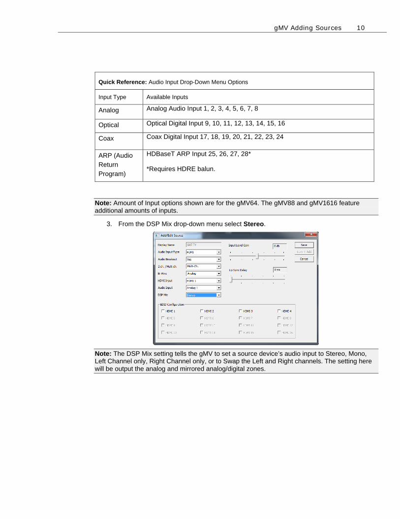
3. From the DSP Mix drop-down menu select Stereo.
Note: The DSP Mix setting tells the gMV to set a source device’s audio input to Stereo, Mono, Left Channel only, Right Channel only, or to Swap the Left and Right channels. The setting here will be output the analog and mirrored analog/digital zones.
gMV Adding Sources 11
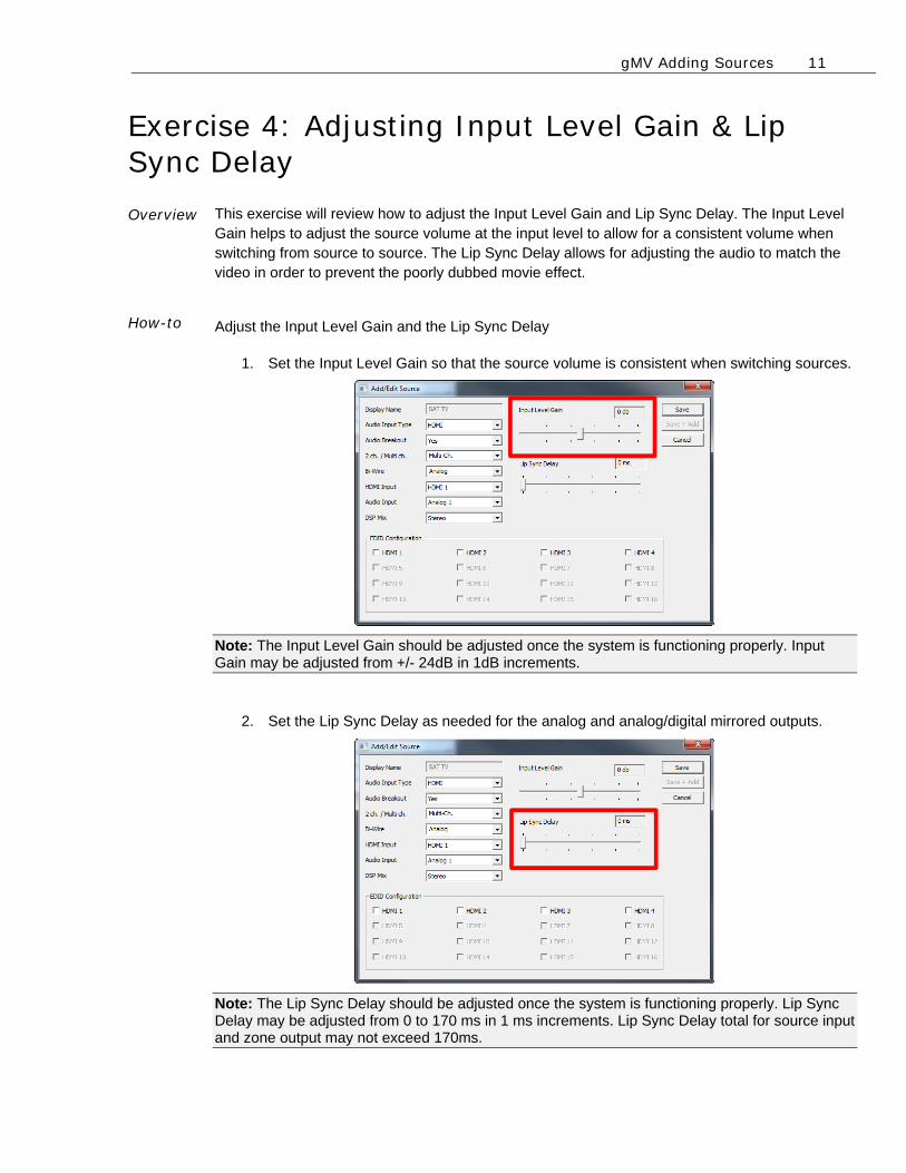
Exercise 4: Adjusting Input Level Gain & Lip Sync Delay Overview How-to
This exercise will review how to adjust the Input Level Gain and Lip Sync Delay. The Input Level Gain helps to adjust the source volume at the input level to allow for a consistent volume when switching from source to source. The Lip Sync Delay allows for adjusting the audio to match the video in order to prevent the poorly dubbed movie effect.
Adjust the Input Level Gain and the Lip Sync Delay
1. Set the Input Level Gain so that the source volume is consistent when switching sources.
Note: The Input Level Gain should be adjusted once the system is functioning properly. Input Gain may be adjusted from +/- 24dB in 1dB increments.
2. Set the Lip Sync Delay as needed for the analog and analog/digital mirrored outputs.
Note: The Lip Sync Delay should be adjusted once the system is functioning properly. Lip Sync Delay may be adjusted from 0 to 170 ms in 1 ms increments. Lip Sync Delay total for source input and zone output may not exceed 170ms.
gMV Adding Sources 12
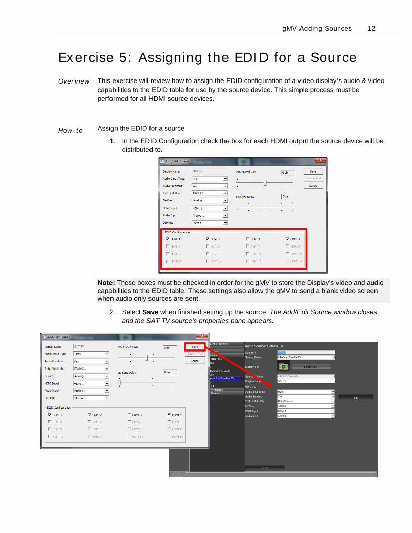
Exercise 5: Assigning the EDID for a Source Overview How-to
This exercise will review how to assign the EDID configuration of a video display’s audio & video capabilities to the EDID table for use by the source device. This simple process must be performed for all HDMI source devices.
Assign the EDID for a source
1. In the EDID Configuration check the box for each HDMI output the source device will be distributed to.
Note: These boxes must be checked in order for the gMV to store the Display’s video and audio capabilities to the EDID table. These settings also allow the gMV to send a blank video screen when audio only sources are sent.
2. Select Save when finished setting up the source. The Add/Edit Source window closes and the SAT TV source’s properties pane appears.
gMV Adding Sources 13
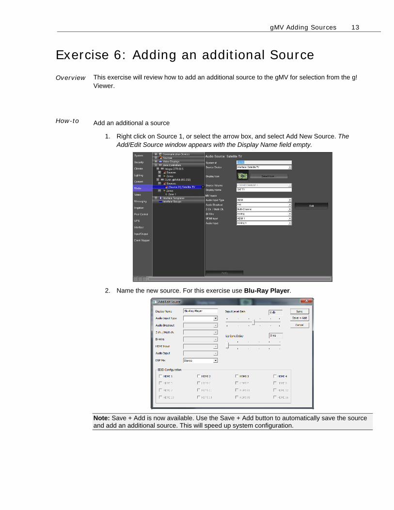
Exercise 6: Adding an additional Source Overview
How-to
This exercise will review how to add an additional source to the gMV for selection from the g! Viewer.
Add an additional a source
1. Right click on Source 1, or select the arrow box, and select Add New Source. The Add/Edit Source window appears with the Display Name field empty.
2. Name the new source. For this exercise use Blu-Ray Player.
Note: Save + Add is now available. Use the Save + Add button to automatically save the source and add an additional source. This will speed up system configuration.
gMV Adding Sources 14
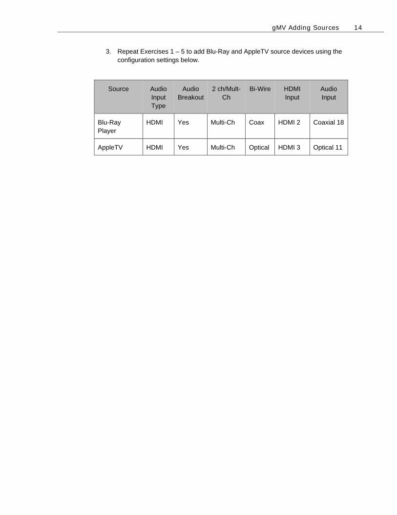
3. Repeat Exercises 1 – 5 to add Blu-Ray and AppleTV source devices using the configuration settings below.
Source Audio Input Type
Audio Breakout
2 ch/Mult-Ch
Bi-Wire HDMI Input
Audio Input
Blu-Ray Player
HDMI Yes Multi-Ch Coax HDMI 2 Coaxial 18
AppleTV HDMI Yes Multi-Ch Optical HDMI 3 Optical 11

gMV Adding Sources 15
Notes: _____________________________________________________________________________
_____________________________________________________________________________
_____________________________________________________________________________
_____________________________________________________________________________
_____________________________________________________________________________
_____________________________________________________________________________
_____________________________________________________________________________
_____________________________________________________________________________
_____________________________________________________________________________
_____________________________________________________________________________
_____________________________________________________________________________
_____________________________________________________________________________
_____________________________________________________________________________
_____________________________________________________________________________
_____________________________________________________________________________
_____________________________________________________________________________
_____________________________________________________________________________
_____________________________________________________________________________
_____________________________________________________________________________
_____________________________________________________________________________
_____________________________________________________________________________
_____________________________________________________________________________
_____________________________________________________________________________
_____________________________________________________________________________
_____________________________________________________________________________
_____________________________________________________________________________
_____________________________________________________________________________
_____________________________________________________________________________
_____________________________________________________________________________
_____________________________________________________________________________
Lesson 3 gMV Adding Zones
Overview
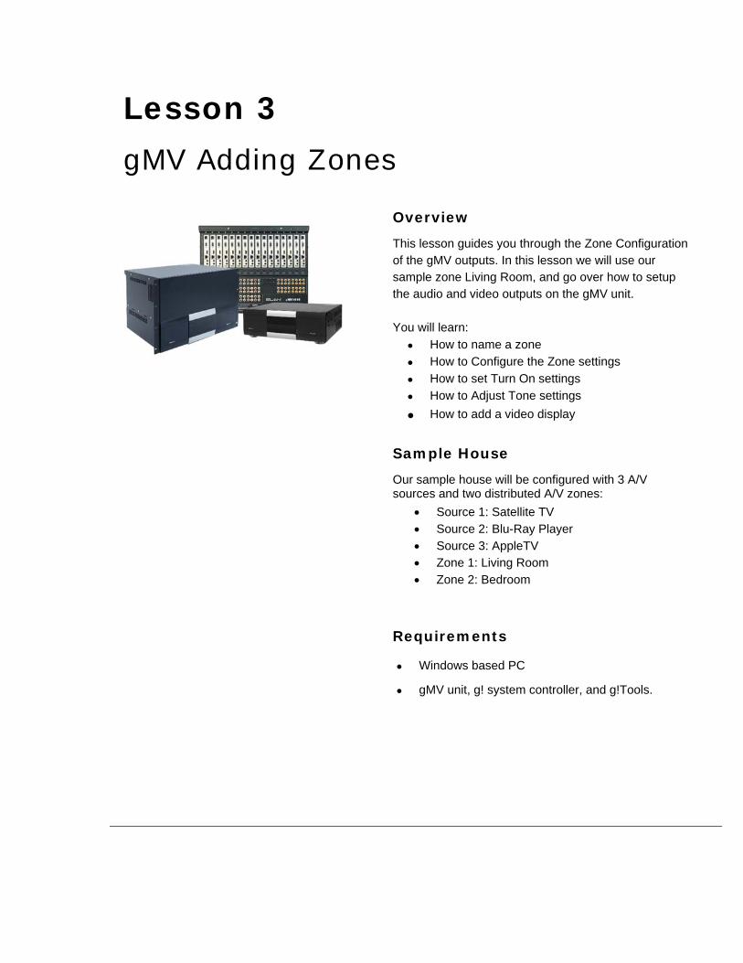
This lesson guides you through the Zone Configuration of the gMV outputs. In this lesson we will use our sample zone Living Room, and go over how to setup the audio and video outputs on the gMV unit. You will learn:
How to name a zone
How to Configure the Zone settings
How to set Turn On settings
How to Adjust Tone settings
How to add a video display
Sample House
Our sample house will be configured with 3 A/V sources and two distributed A/V zones:
Source 1: Satellite TV Source 2: Blu-Ray Player Source 3: AppleTV Zone 1: Living Room Zone 2: Bedroom
Requirements
Windows based PC
gMV unit, g! system controller, and g!Tools.
gMV Adding Zones 2
Exercise 1: Zone Name Overview Beginning with this exercise, you will set up the Zone Name for the Zone Controller.
Giving the zones user-friendly names, such as “Living Room” and “Bedroom” for our sample
house, will provide the homeowner with an intuitive interface for controlling the audio/video in their
home.
Due to the amount of possible zone configuration options the gMV will only populate in the System
Node Tree with 1 zone. Additional zones will need to be added manually.
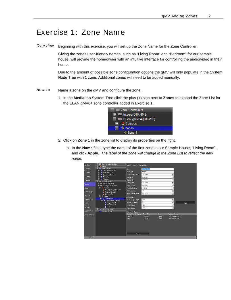
How-to Name a zone on the gMV and configure the zone.
1. In the Media tab System Tree click the plus (+) sign next to Zones to expand the Zone List for
the ELAN gMV64 zone controller added in Exercise 1.
2. Click on Zone 1 in the zone list to display its properties on the right.
a. In the Name field, type the name of the first zone in our Sample House, “Living Room”,
and click Apply. The label of the zone will change in the Zone List to reflect the new
name.
gMV Adding Zones 3
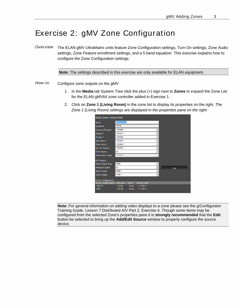
Exercise 2: gMV Zone Configuration Overview The ELAN gMV UltraMatrix units feature Zone Configuration settings, Turn On settings, Zone Audio
settings, Zone Feature enrollment settings, and a 5 band equalizer. This exercise explains how to
configure the Zone Configuration settings.
Note: The settings described in this exercise are only available for ELAN equipment.
How-to
Configure zone outputs on the gMV
1. In the Media tab System Tree click the plus (+) sign next to Zones to expand the Zone List
for the ELAN gMV64 zone controller added in Exercise 1.
2. Click on Zone 1 (Living Room) in the zone list to display its properties on the right. The
Zone 1 (Living Room) settings are displayed in the properties pane on the right:
Note: For general information on adding video displays to a zone please see the g!Configurator Training Guide, Lesson 7 Distributed A/V Part 2, Exercise 4. Though some items may be configured from the selected Zone’s properties pane it is strongly recommended that the Edit button be selected to bring up the Add/Edit Source window to properly configure the source device.
gMV Adding Zones 4
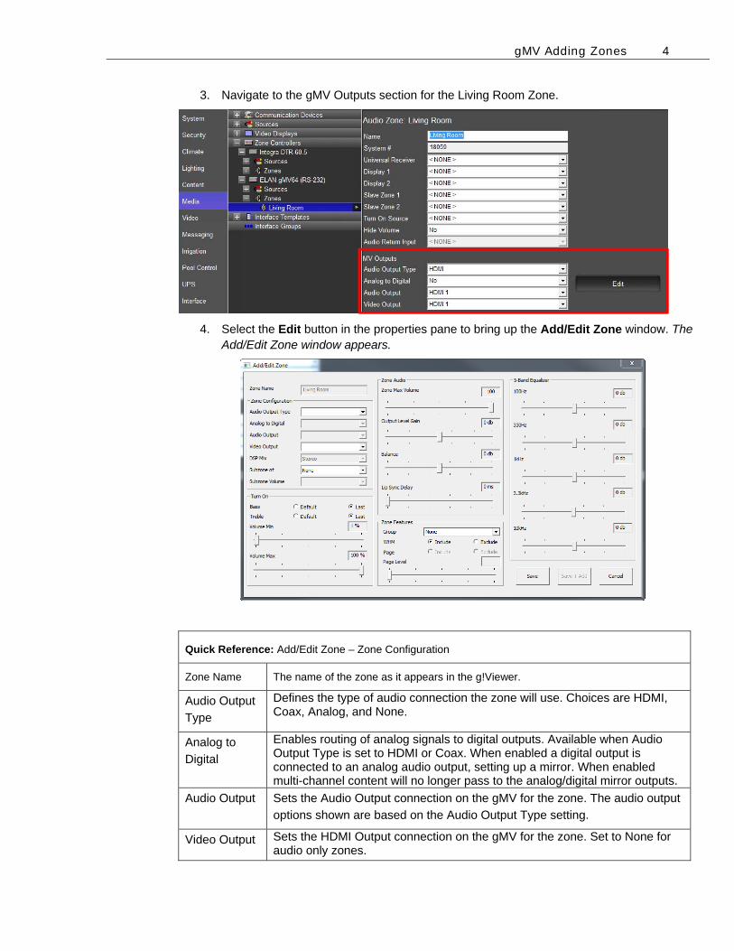
3. Navigate to the gMV Outputs section for the Living Room Zone.
4. Select the Edit button in the properties pane to bring up the Add/Edit Zone window. The Add/Edit Zone window appears.
Quick Reference: Add/Edit Zone – Zone Configuration
Zone Name The name of the zone as it appears in the g!Viewer.
Audio Output
Type
Defines the type of audio connection the zone will use. Choices are HDMI, Coax, Analog, and None.
Analog to
Digital
Enables routing of analog signals to digital outputs. Available when Audio Output Type is set to HDMI or Coax. When enabled a digital output is connected to an analog audio output, setting up a mirror. When enabled multi-channel content will no longer pass to the analog/digital mirror outputs.
Audio Output Sets the Audio Output connection on the gMV for the zone. The audio output
options shown are based on the Audio Output Type setting.
Video Output Sets the HDMI Output connection on the gMV for the zone. Set to None for audio only zones.
gMV Adding Zones 5
DSP Mix Sets the audio outputs on the gMV to Stereo, Mono, Left only, Right only, or
Swap the L/R channels.
Subzone of Sets the master zone. When a master zone is set, all source and power
selections made in either the master zone or subzone will track.
Subzone
Volume
Set the subzone volume to be Independent or Synced with the master zone.
This setting is only available if the Subzone of is being used.
Save Saves the zone configuration and closes the Add/Edit Zone window.
Save + Add Saves the zone configuration and adds an additional zone. This setting is
only available after a second zone has been added.
Cancel Exits the Add/Edit Zone window without saving any configuration changes.
One zone must exist in the gMV node tree in order for this option to be
available.
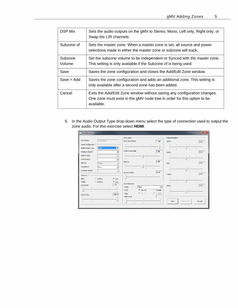
5. In the Audio Output Type drop-down menu select the type of connection used to output the zone audio. For this exercise select HDMI.
gMV Adding Zones 6
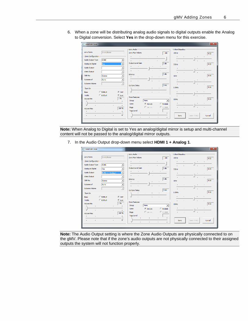
6. When a zone will be distributing analog audio signals to digital outputs enable the Analog to Digital conversion. Select Yes in the drop-down menu for this exercise.
Note: When Analog to Digital is set to Yes an analog/digital mirror is setup and multi-channel content will not be passed to the analog/digital mirror outputs.
7. In the Audio Output drop-down menu select HDMI 1 + Analog 1.
Note: The Audio Output setting is where the Zone Audio Outputs are physically connected to on the gMV. Please note that if the zone’s audio outputs are not physically connected to their assigned outputs the system will not function properly.
gMV Adding Zones 7
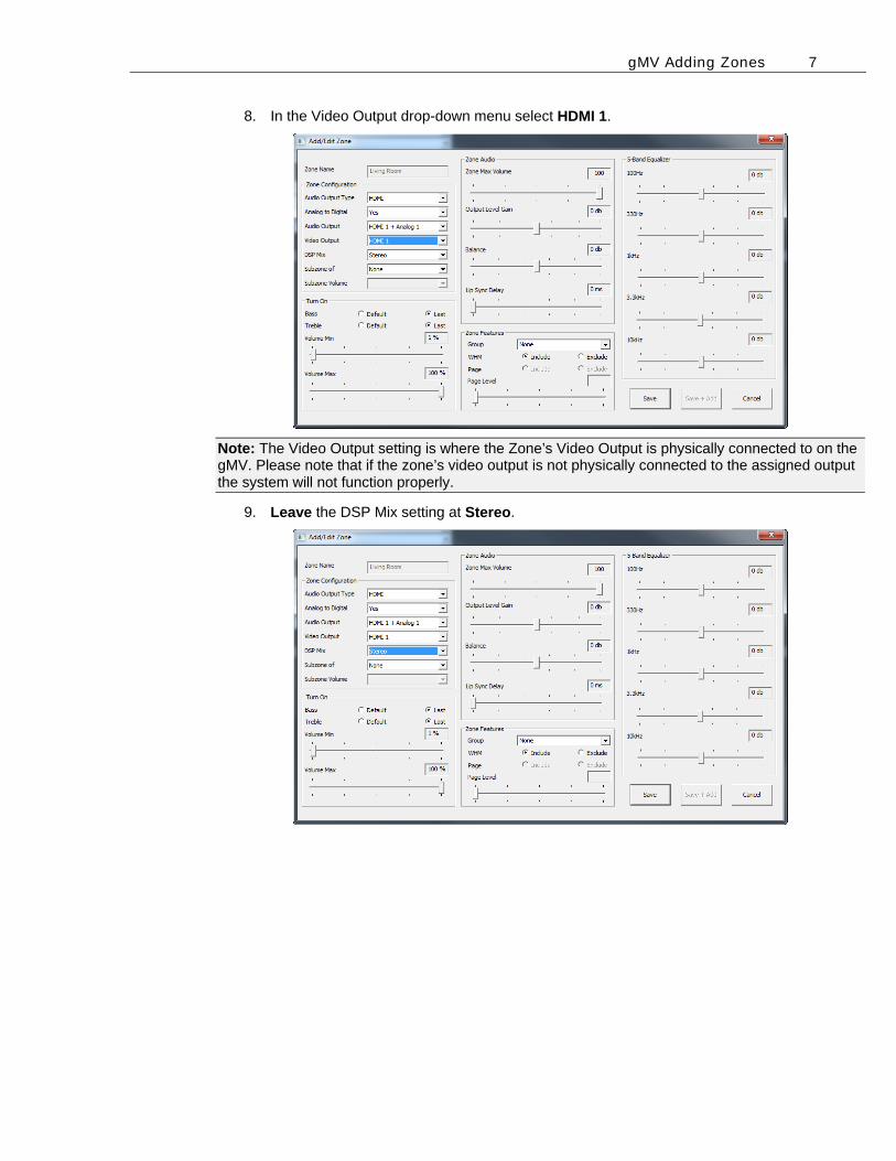
8. In the Video Output drop-down menu select HDMI 1.
Note: The Video Output setting is where the Zone’s Video Output is physically connected to on the gMV. Please note that if the zone’s video output is not physically connected to the assigned output the system will not function properly.
9. Leave the DSP Mix setting at Stereo.
gMV Adding Zones 8
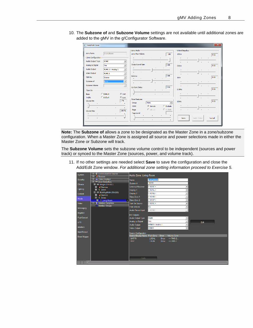
10. The Subzone of and Subzone Volume settings are not available until additional zones are added to the gMV in the g!Configurator Software.
Note: The Subzone of allows a zone to be designated as the Master Zone in a zone/subzone configuration. When a Master Zone is assigned all source and power selections made in either the Master Zone or Subzone will track.
The Subzone Volume sets the subzone volume control to be independent (sources and power track) or synced to the Master Zone (sources, power, and volume track).
11. If no other settings are needed select Save to save the configuration and close the Add/Edit Zone window. For additional zone setting information proceed to Exercise 5.
gMV Adding Zones 9
Overview How To
Exercise 3: gMV Zone Turn On Settings The gMV UltraMatrix units feature Turn On settings for each zone to adjust Bass, Treble, and Turn On volume. When set up, the Turn On settings ensure that an end user will have the best possible sound when a zone is turned on. Exercise 3 will go over how to set up the Turn On setting for a gMV zone. Note: The Turn On settings should be performed after the system is operational in order to properly test bass, treble, and turn on volume settings.
Set the Turn On Tone and Volume settings
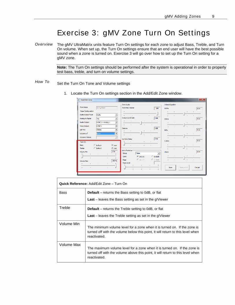
1. Locate the Turn On settings section in the Add/Edit Zone window.
Quick Reference: Add/Edit Zone – Turn On
Bass Default – returns the Bass setting to 0dB, or flat
Last – leaves the Bass setting as set in the g!Viewer
Treble Default – returns the Treble setting to 0dB, or flat
Last – leaves the Treble setting as set in the g!Viewer
Volume Min The minimum volume level for a zone when it is turned on. If the zone is turned off with the volume below this point, it will return to this level when reactivated.
Volume Max The maximum volume level for a zone when it is turned on. If the zone is turned off with the volume above this point, it will return to this level when reactivated.
gMV Adding Zones 10
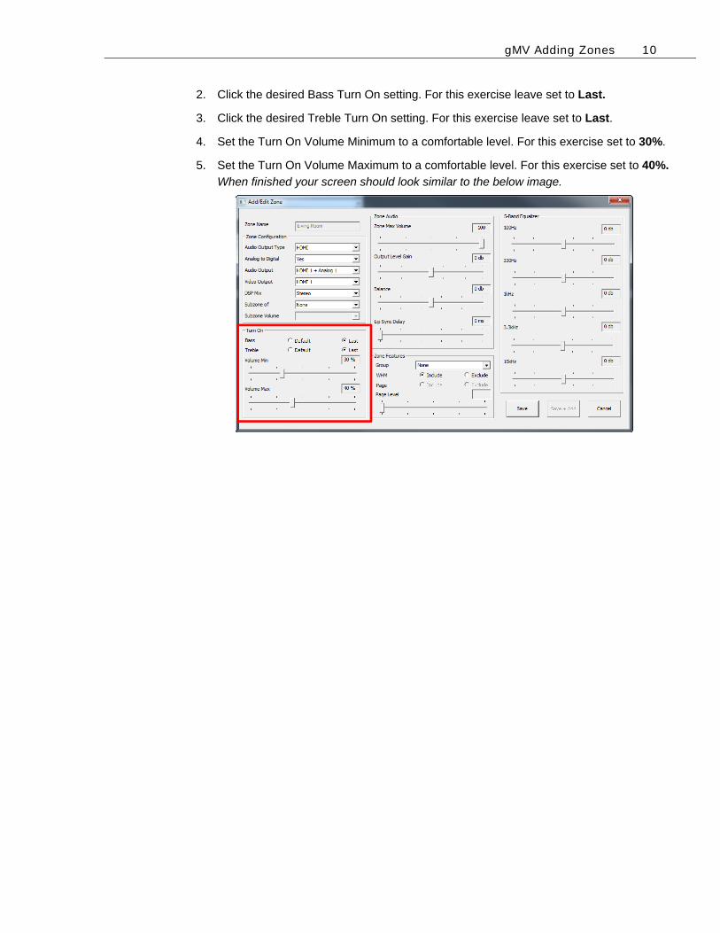
2. Click the desired Bass Turn On setting. For this exercise leave set to Last.
3. Click the desired Treble Turn On setting. For this exercise leave set to Last.
4. Set the Turn On Volume Minimum to a comfortable level. For this exercise set to 30%.
5. Set the Turn On Volume Maximum to a comfortable level. For this exercise set to 40%.
When finished your screen should look similar to the below image.

gMV Adding Zones 11
Overview How To
Exercise 4: gMV Zone Audio Settings The gMV UltraMatrix units feature adjustable settings for Maximum Zone Volume, Output Level Gain, Balance, and Lip Sync Delay. These settings are used to ensure that the audio played in a zone will provide an enjoyable listening experience. Exercise 4 will go over how to set up the Zone Audio settings for a gMV zone. Note: The Zone Audio settings should be performed after the system is operational in order to properly test Zone Max Volume, Output Level Gain, Balance adjustments, and Lip Sync Delay.
Adjust the Zone Max Volume and Lip Sync Delay settings
1. Locate Zone Audio settings in the Add/Edit Zone window.
Quick Reference: Add/Edit Zone – Zone Audio
Zone Max
Volume
Sets the maximum volume level for a zone. This setting may not
be lower than 40.
Output Level
Gain
Adjusts the output level for the zone +/- 24dB in 1dB increments.
This setting is useful when sub-zoning and the subzone volume
levels need to be quieter or louder than the main zone.
Balance Adjusts the gain between the left and right channels to set the
playback position in the stereo field.
Lip Sync
Delay
Sets the delay of the analog and analog/digital mirror outputs for
the zone output in ms. A total of 170ms adjustment is available
between both source input and zone output adjustments.
gMV Adding Zones 12
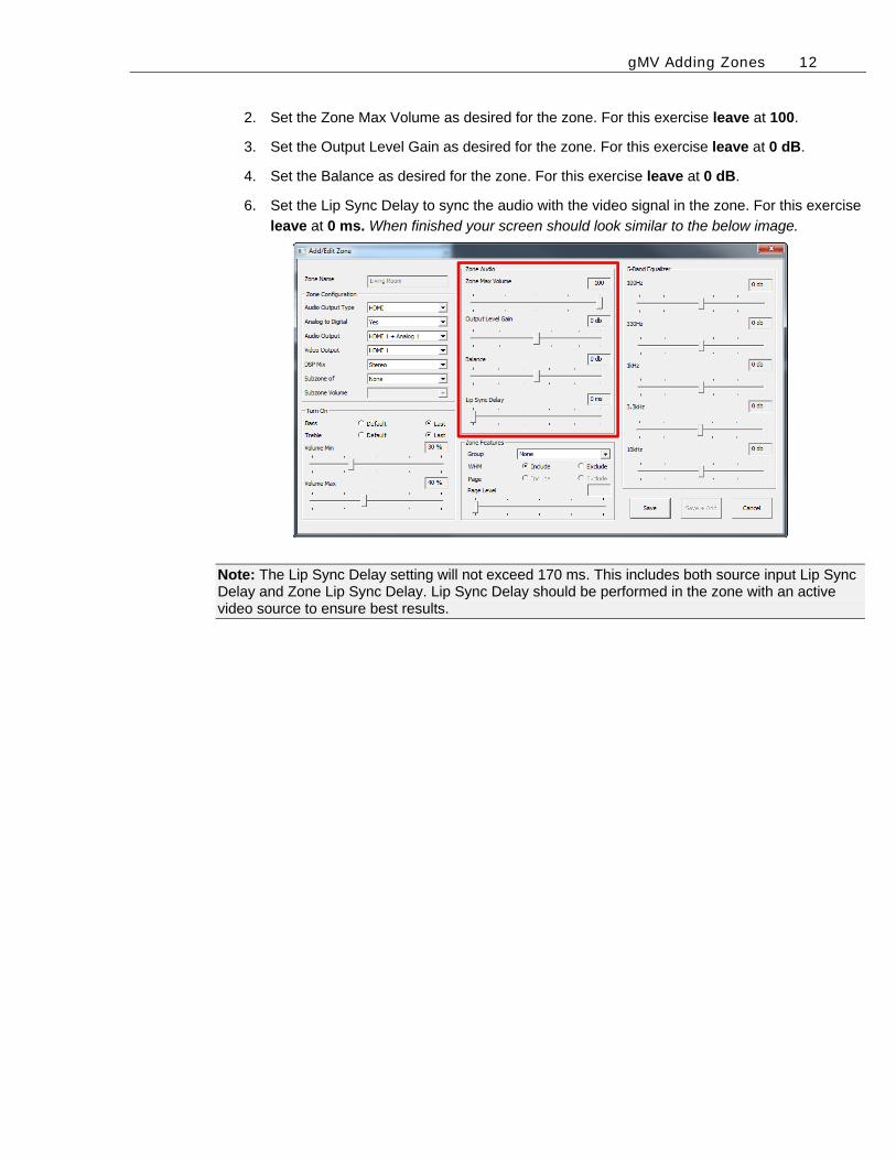
2. Set the Zone Max Volume as desired for the zone. For this exercise leave at 100.
3. Set the Output Level Gain as desired for the zone. For this exercise leave at 0 dB.
4. Set the Balance as desired for the zone. For this exercise leave at 0 dB.
6. Set the Lip Sync Delay to sync the audio with the video signal in the zone. For this exercise
leave at 0 ms. When finished your screen should look similar to the below image.
Note: The Lip Sync Delay setting will not exceed 170 ms. This includes both source input Lip Sync Delay and Zone Lip Sync Delay. Lip Sync Delay should be performed in the zone with an active video source to ensure best results.
gMV Adding Zones 13
Overview How To
Exercise 5: gMV Zone Feature Settings The gMV UltraMatrix units have adjustable Zone Features that include Zone Grouping, WHM inclusion, Page/Doorbell Inclusion, and Page/Doorbell Level adjustments. These settings are used to make the system easier to navigate in the g!Viewer and thus become more user friendly. Exercise 5 will go over how to set up the Zone Features settings for a gMV zone.
Set up the Zone Groups, WHM, and Paging/Doorbell Features
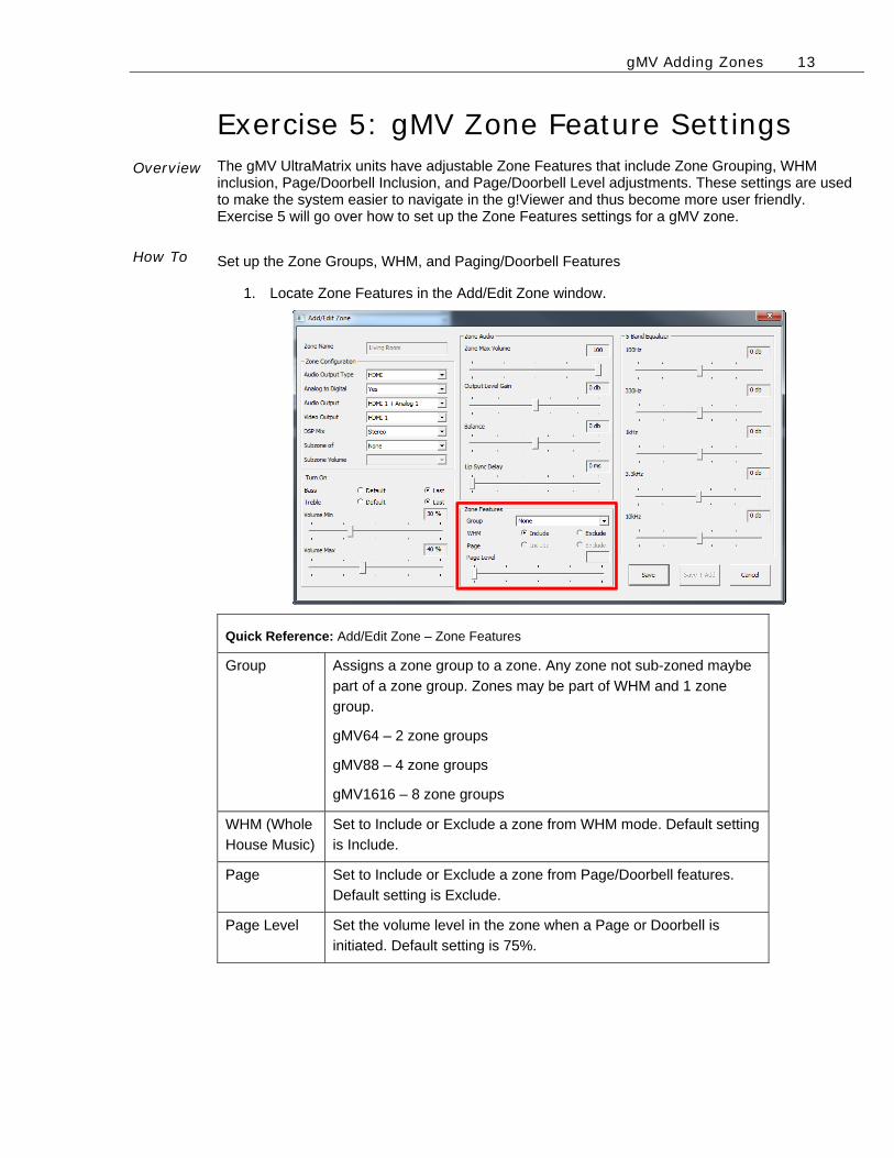
1. Locate Zone Features in the Add/Edit Zone window.
Quick Reference: Add/Edit Zone – Zone Features
Group Assigns a zone group to a zone. Any zone not sub-zoned maybe
part of a zone group. Zones may be part of WHM and 1 zone
group.
gMV64 – 2 zone groups
gMV88 – 4 zone groups
gMV1616 – 8 zone groups
WHM (Whole
House Music)
Set to Include or Exclude a zone from WHM mode. Default setting
is Include.
Page Set to Include or Exclude a zone from Page/Doorbell features.
Default setting is Exclude.
Page Level Set the volume level in the zone when a Page or Doorbell is
initiated. Default setting is 75%.
gMV Adding Zones 14
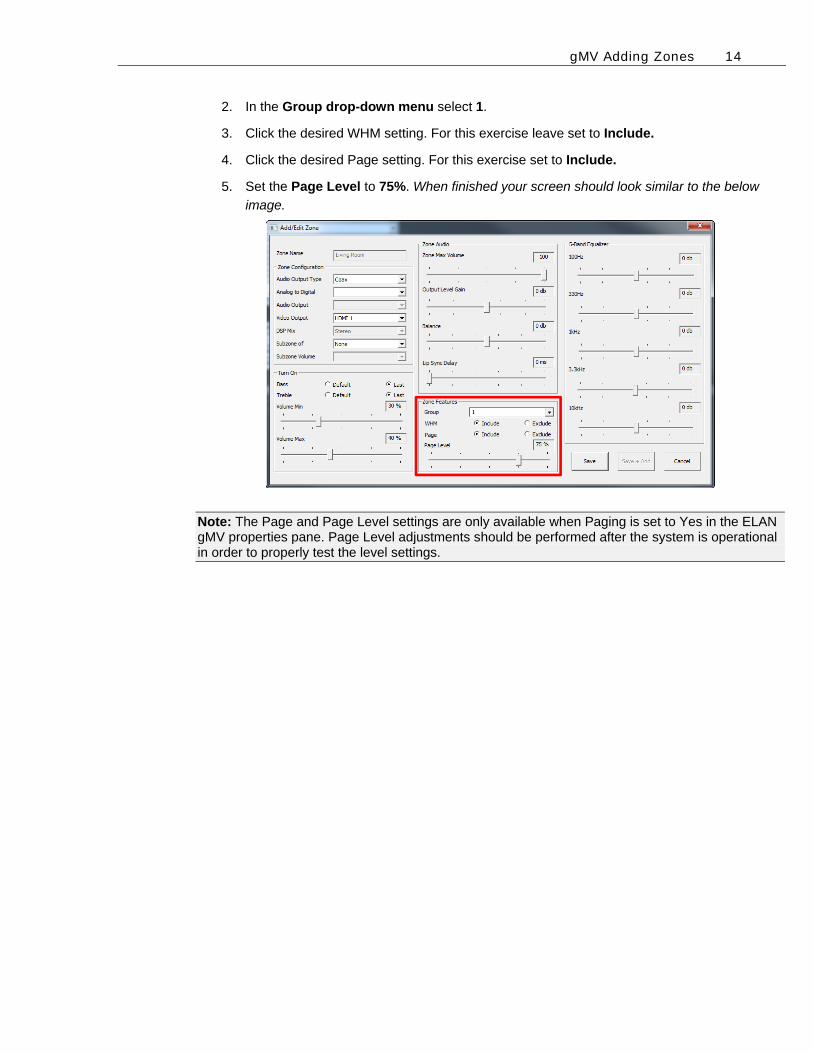
2. In the Group drop-down menu select 1.
3. Click the desired WHM setting. For this exercise leave set to Include.
4. Click the desired Page setting. For this exercise set to Include.
5. Set the Page Level to 75%. When finished your screen should look similar to the below
image.
Note: The Page and Page Level settings are only available when Paging is set to Yes in the ELAN gMV properties pane. Page Level adjustments should be performed after the system is operational in order to properly test the level settings.
gMV Adding Zones 15
Overview How To
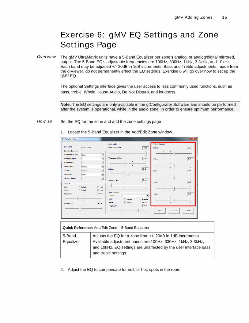
Exercise 6: gMV EQ Settings and Zone Settings Page The gMV UltraMatrix units have a 5-Band Equalizer per zone’s analog, or analog/digital mirrored, output. The 5-Band EQ’s adjustable frequencies are 100Hz, 330Hz, 1kHz, 3.3kHz, and 10kHz. Each band may be adjusted +/- 20dB in 1dB increments. Bass and Treble adjustments, made from the g!Viewer, do not permanently effect the EQ settings. Exercise 6 will go over how to set up the gMV EQ.
The optional Settings interface gives the user access to less commonly used functions, such as
bass, treble, Whole House Audio, Do Not Disturb, and loudness.
Note: The EQ settings are only available in the g!Configurator Software and should be performed after the system is operational, while in the audio zone, in order to ensure optimum performance.
Set the EQ for the zone and add the zone settings page
1. Locate the 5-Band Equalizer in the Add/Edit Zone window.
Quick Reference: Add/Edit Zone – 5-Band Equalizer
5-Band
Equalizer
Adjusts the EQ for a zone from +/- 20dB in 1dB increments.
Available adjustment bands are 100Hz, 330Hz, 1kHz, 3.3kHz,
and 10kHz. EQ settings are unaffected by the user interface bass
and treble settings.
2. Adjust the EQ to compensate for null, or hot, spots in the room.
gMV Adding Zones 16
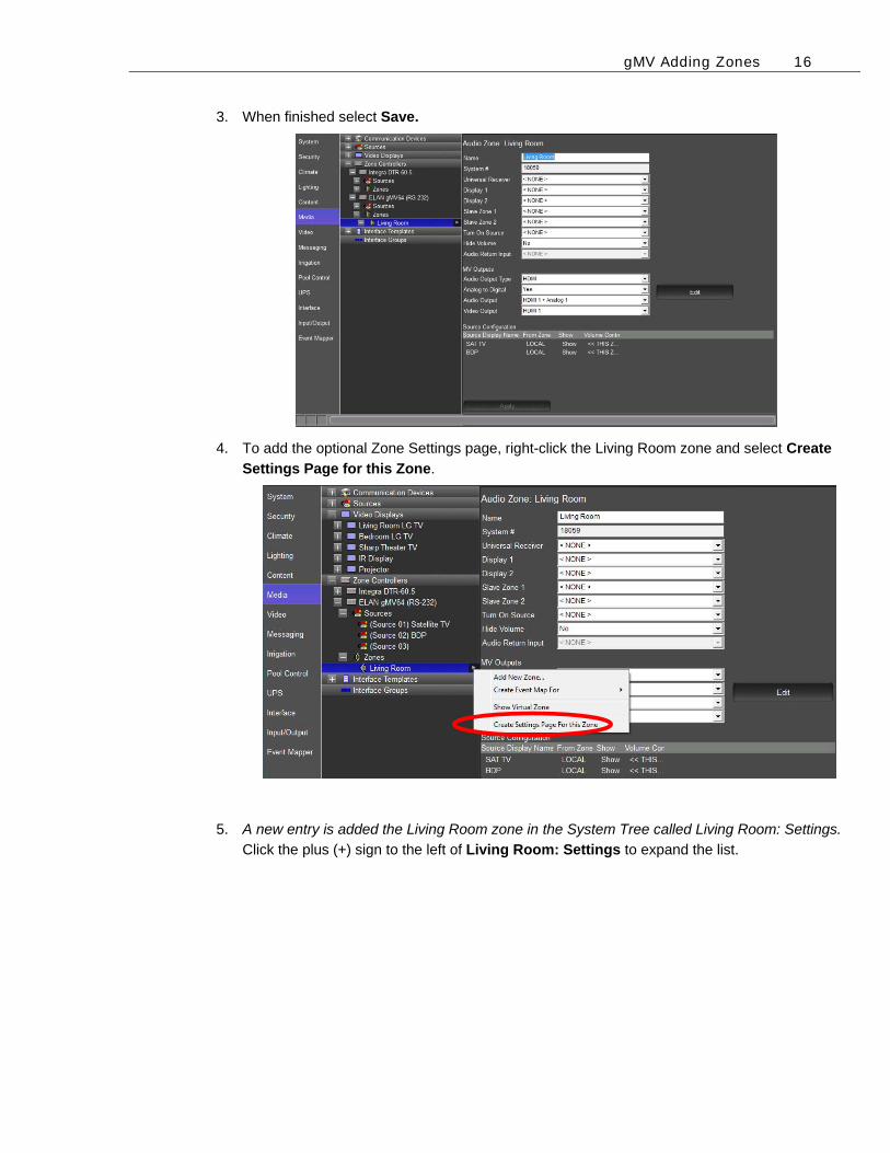
3. When finished select Save.
4. To add the optional Zone Settings page, right-click the Living Room zone and select Create
Settings Page for this Zone.
5. A new entry is added the Living Room zone in the System Tree called Living Room: Settings.
Click the plus (+) sign to the left of Living Room: Settings to expand the list.
gMV Adding Zones 17
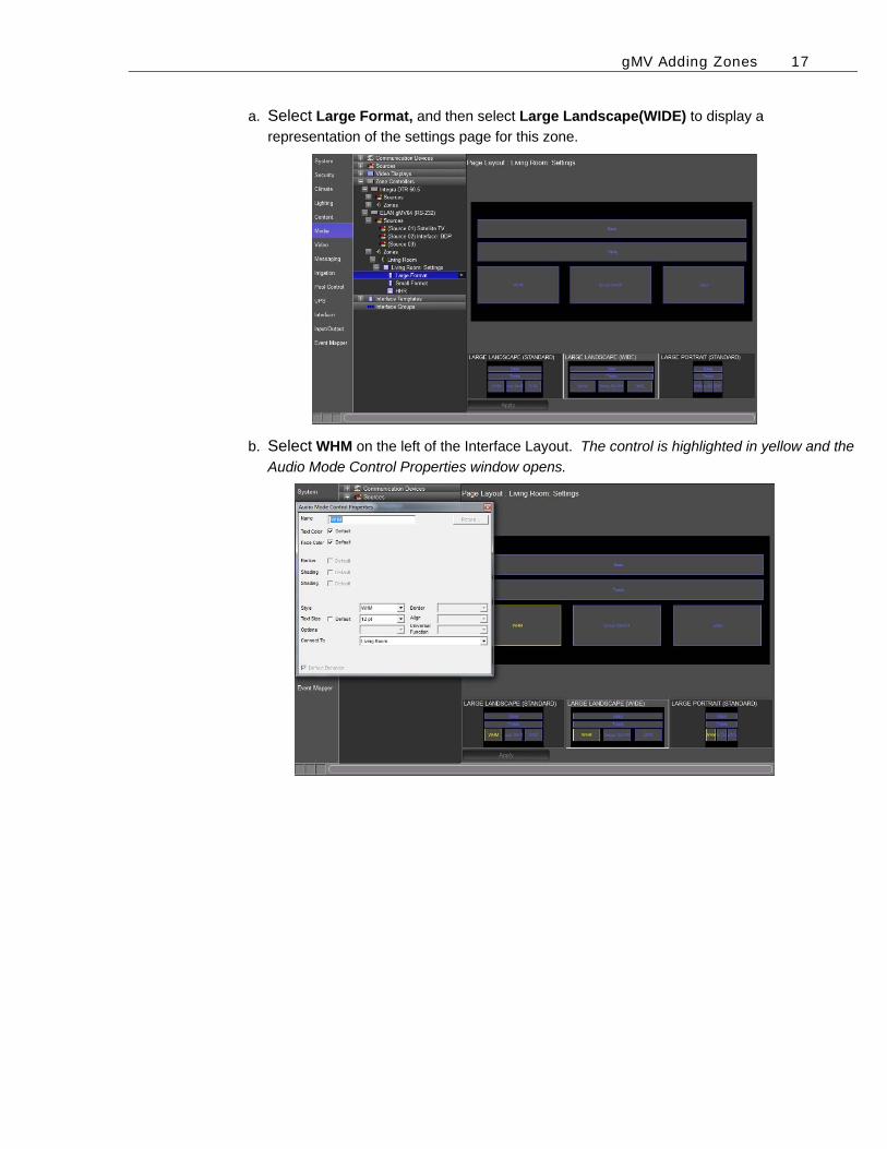
a. Select Large Format, and then select Large Landscape(WIDE) to display a
representation of the settings page for this zone.
b. Select WHM on the left of the Interface Layout. The control is highlighted in yellow and the
Audio Mode Control Properties window opens.
gMV Adding Zones 18
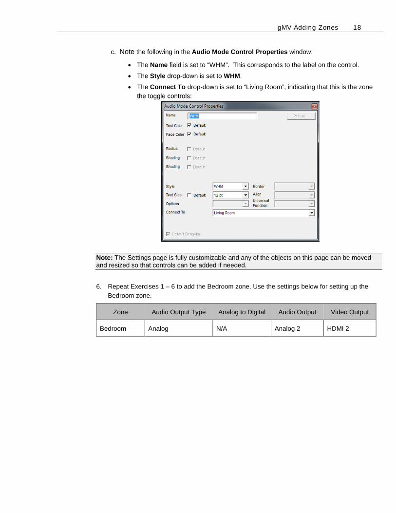
c. Note the following in the Audio Mode Control Properties window:
The Name field is set to “WHM”. This corresponds to the label on the control.
The Style drop-down is set to WHM.
The Connect To drop-down is set to “Living Room”, indicating that this is the zone
the toggle controls:
Note: The Settings page is fully customizable and any of the objects on this page can be moved and resized so that controls can be added if needed.
6. Repeat Exercises 1 – 6 to add the Bedroom zone. Use the settings below for setting up the
Bedroom zone.
Zone Audio Output Type Analog to Digital Audio Output Video Output
Bedroom Analog N/A Analog 2 HDMI 2
gMV Adding Zones 19
Exercise 7: Display Setup Overview Once all the Zone settings have been configured the video displays may be added to a zone.
This exercise will demonstrate how to assign video display(s) for the Zone Controller. This step is
performed after the gMV zone has been configured.
Note: The exercise assumes that display devices have already been created in the g! Configurator. For information on how to add a video display in the Media tab please see the g!Configurator Training Guide, Lesson 7 Distributed A/V Part 2.
How-to Assign a video display.
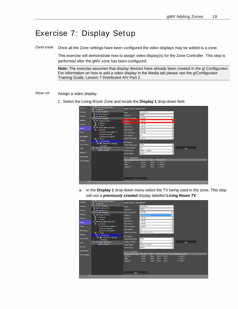
1. Select the Living Room Zone and locate the Display 1 drop-down field.
a. In the Display 1 drop-down menu select the TV being used in the zone. This step
will use a previously created display labelled Living Room TV.
gMV Adding Zones 20
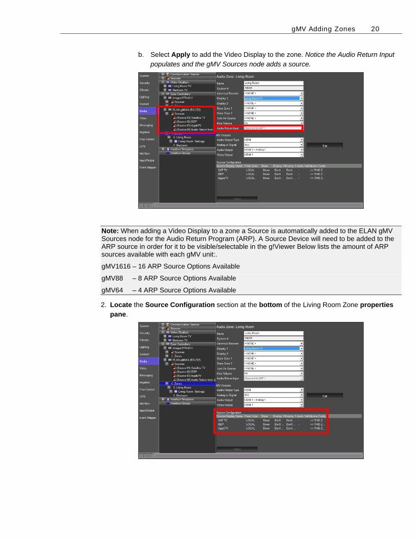
b. Select Apply to add the Video Display to the zone. Notice the Audio Return Input
populates and the gMV Sources node adds a source.
Note: When adding a Video Display to a zone a Source is automatically added to the ELAN gMV Sources node for the Audio Return Program (ARP). A Source Device will need to be added to the ARP source in order for it to be visible/selectable in the g!Viewer Below lists the amount of ARP sources available with each gMV unit:.
gMV1616 – 16 ARP Source Options Available
gMV88 – 8 ARP Source Options Available
gMV64 – 4 ARP Source Options Available
2. Locate the Source Configuration section at the bottom of the Living Room Zone properties
pane.
gMV Adding Zones 21
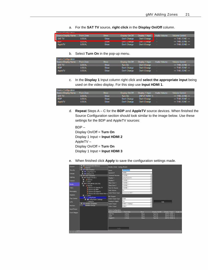
a. For the SAT TV source, right click in the Display On/Off column.
b. Select Turn On in the pop-up menu.
c. In the Display 1 Input column right click and select the appropriate input being
used on the video display. For this step use Input HDMI 1.
d. Repeat Steps A – C for the BDP and AppleTV source devices. When finished the
Source Configuration section should look similar to the image below. Use these
settings for the BDP and AppleTV sources:
BDP –
Display On/Off = Turn On
Display 1 Input = Input HDMI 2
AppleTV –
Display On/Off = Turn On
Display 1 Input = Input HDMI 3
e. When finished click Apply to save the configuration settings made.

gMV Adding Zones 22
Notes: _____________________________________________________________________________
_____________________________________________________________________________
_____________________________________________________________________________
_____________________________________________________________________________
_____________________________________________________________________________
_____________________________________________________________________________
_____________________________________________________________________________
_____________________________________________________________________________
_____________________________________________________________________________
_____________________________________________________________________________
_____________________________________________________________________________
_____________________________________________________________________________
_____________________________________________________________________________
_____________________________________________________________________________
_____________________________________________________________________________
_____________________________________________________________________________
_____________________________________________________________________________
_____________________________________________________________________________
_____________________________________________________________________________
_____________________________________________________________________________
_____________________________________________________________________________
_____________________________________________________________________________
_____________________________________________________________________________
_____________________________________________________________________________
_____________________________________________________________________________
_____________________________________________________________________________
_____________________________________________________________________________
_____________________________________________________________________________
_____________________________________________________________________________
_____________________________________________________________________________
Lesson 4 gMV in the g!Viewer
Overview
This lesson goes over terminology and the steps used in the g!Configurator Software for setting up a gMV unit. You will learn:
How to add gMV zones to the g!Viewer
To check the gMV operation from the g!Viewer
Sample House
Our sample house will be configured with 3 A/V sources and two distributed A/V zones:
Source 1: Satellite TV Source 2: Blu-Ray Player Source 3: AppleTV Zone 1: Living Room Zone 2: Bedroom
Requirements
Windows based PC
gMV unit, g! system controller, and g!Tools.

gMV g!Viewer 2
Exercise 1: Adding Zones to the Viewer Overview At this point, you have added in a Zone Controller with a total of 2 zones. However, only two of
those zones will actually be used—the Living Room and the Bedroom. The next step is to remove the unused zones from the Viewer so that the homeowner sees an uncluttered and intuitive interface.
How-to To remove the unused zones from the Viewer interface:
1. Select the Interface tab in the Configurator.
2. Under Interface Devices (TouchScreen) near the top of the System Tree, click the plus (+)
sign to the left of the Windows option to expand the list.
3. Select Tab Config: Media System. The list of available/visible zones for the media system
display in the properties window on the right.
Visible Tabs= zones that appear in the Viewer for the homeowner to use.
Available Tabs= zones that are not currently displayed in the Viewer.
Since the Living Room and Bedroom zones are active in our Sample House, we need these
zones to be in the Visible Tabs list. All of the remaining zones can be put in the Available tabs
column hiding them from the viewer interface.
gMV g!Viewer 3
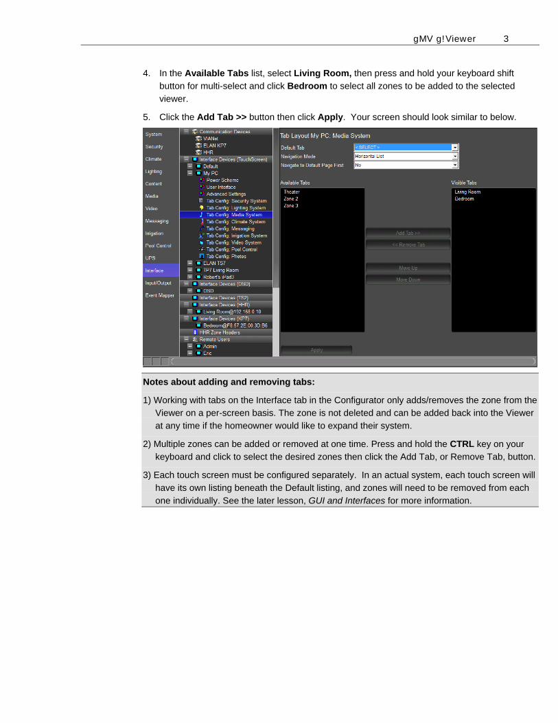
4. In the Available Tabs list, select Living Room, then press and hold your keyboard shift
button for multi-select and click Bedroom to select all zones to be added to the selected
viewer.
5. Click the Add Tab >> button then click Apply. Your screen should look similar to below.
Notes about adding and removing tabs:
1) Working with tabs on the Interface tab in the Configurator only adds/removes the zone from the
Viewer on a per-screen basis. The zone is not deleted and can be added back into the Viewer
at any time if the homeowner would like to expand their system.
2) Multiple zones can be added or removed at one time. Press and hold the CTRL key on your
keyboard and click to select the desired zones then click the Add Tab, or Remove Tab, button.
3) Each touch screen must be configured separately. In an actual system, each touch screen will
have its own listing beneath the Default listing, and zones will need to be removed from each
one individually. See the later lesson, GUI and Interfaces for more information.
gMV g!Viewer 4
8BExercise 2: Check the Viewer Overview In the previous lessons and exercises you used the Configurator to set up the
ELAN Media system and interfaces. In this exercise you will finally check your configuration in the Viewer.
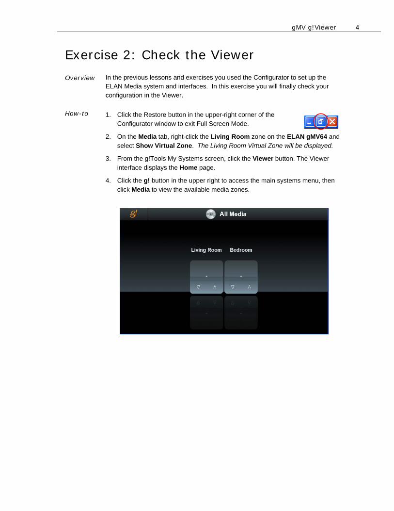
How-to 1. Click the Restore button in the upper-right corner of the
Configurator window to exit Full Screen Mode.
2. On the Media tab, right-click the Living Room zone on the ELAN gMV64 and
select Show Virtual Zone. The Living Room Virtual Zone will be displayed.
3. From the g!Tools My Systems screen, click the Viewer button. The Viewer
interface displays the Home page.
4. Click the g! button in the upper right to access the main systems menu, then
click Media to view the available media zones.
gMV g!Viewer 5
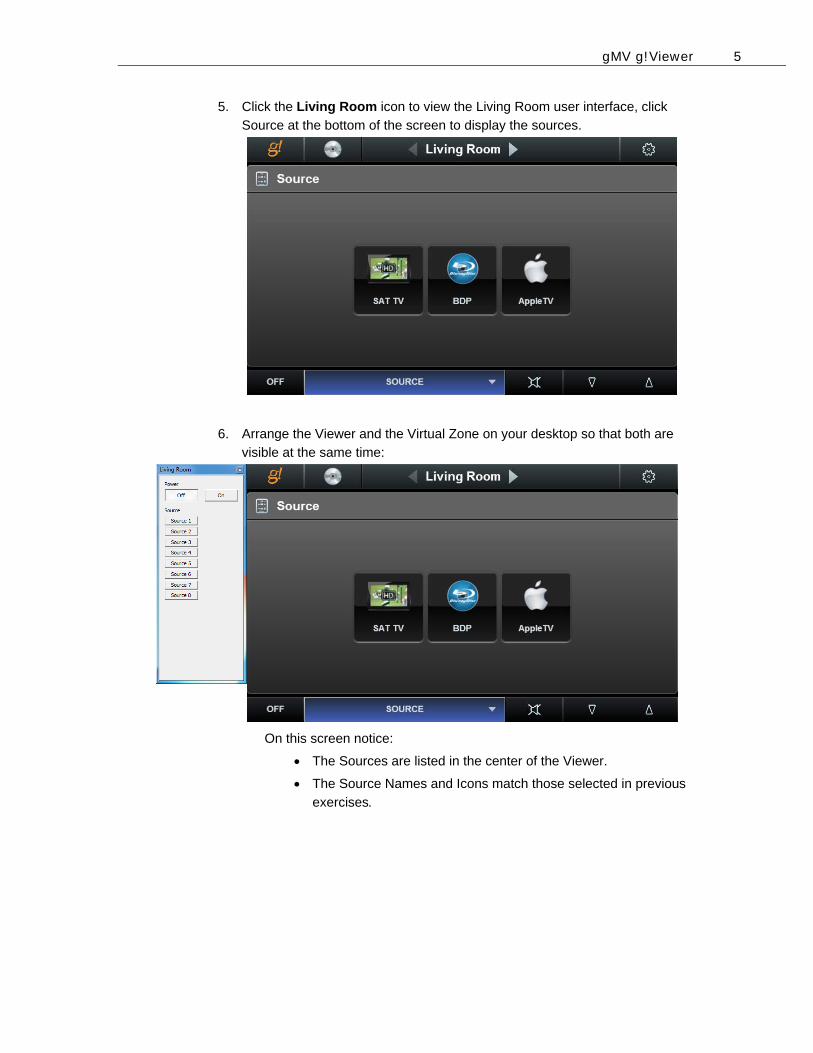
5. Click the Living Room icon to view the Living Room user interface, click
Source at the bottom of the screen to display the sources.
6. Arrange the Viewer and the Virtual Zone on your desktop so that both are
visible at the same time:
On this screen notice:
The Sources are listed in the center of the Viewer.
The Source Names and Icons match those selected in previous
exercises.
gMV g!Viewer 6
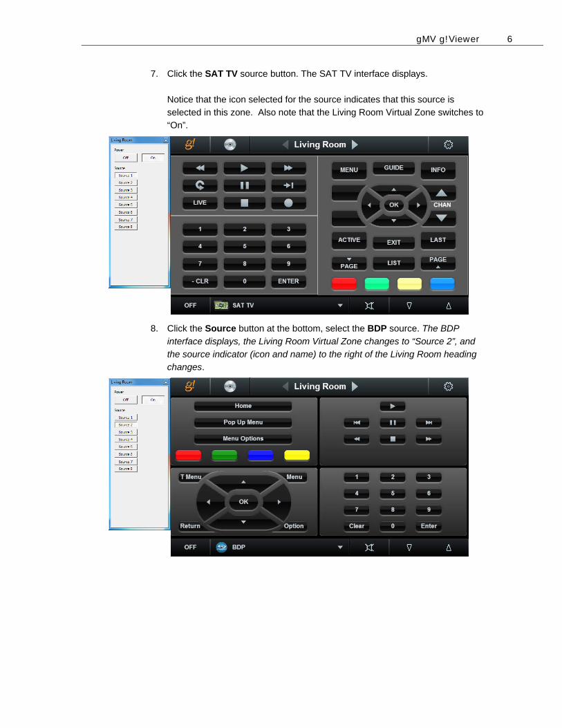
7. Click the SAT TV source button. The SAT TV interface displays.
Notice that the icon selected for the source indicates that this source is
selected in this zone. Also note that the Living Room Virtual Zone switches to
“On”.
8. Click the Source button at the bottom, select the BDP source. The BDP
interface displays, the Living Room Virtual Zone changes to “Source 2”, and
the source indicator (icon and name) to the right of the Living Room heading
changes.
gMV g!Viewer 7
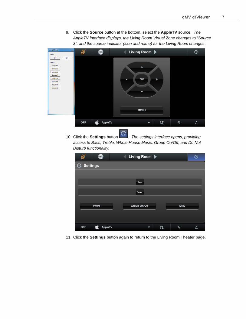
9. Click the Source button at the bottom, select the AppleTV source. The
AppleTV interface displays, the Living Room Virtual Zone changes to “Source
3”, and the source indicator (icon and name) for the Living Room changes.
10. Click the Settings button . The settings interface opens, providing
access to Bass, Treble, Whole House Music, Group On/Off, and Do Not
Disturb functionality.
11. Click the Settings button again to return to the Living Room Theater page.

gMV g!Viewer 8
Notes: _____________________________________________________________________________
_____________________________________________________________________________
_____________________________________________________________________________
_____________________________________________________________________________
_____________________________________________________________________________
_____________________________________________________________________________
_____________________________________________________________________________
_____________________________________________________________________________
_____________________________________________________________________________
_____________________________________________________________________________
_____________________________________________________________________________
_____________________________________________________________________________
_____________________________________________________________________________
_____________________________________________________________________________
_____________________________________________________________________________
_____________________________________________________________________________
_____________________________________________________________________________
_____________________________________________________________________________
_____________________________________________________________________________
_____________________________________________________________________________
_____________________________________________________________________________
_____________________________________________________________________________
_____________________________________________________________________________
_____________________________________________________________________________
_____________________________________________________________________________
_____________________________________________________________________________
_____________________________________________________________________________
_____________________________________________________________________________
_____________________________________________________________________________
_____________________________________________________________________________
B
Lesson 5 gMV Commissioning
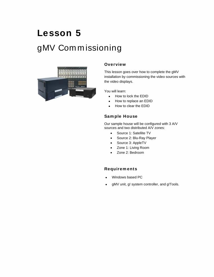
Overview
This lesson goes over how to complete the gMV installation by commissioning the video sources with the video displays. You will learn:
How to lock the EDID
How to replace an EDID
How to clear the EDID
Sample House
Our sample house will be configured with 3 A/V sources and two distributed A/V zones:
Source 1: Satellite TV Source 2: Blu-Ray Player Source 3: AppleTV Zone 1: Living Room Zone 2: Bedroom
Requirements
Windows based PC
gMV unit, g! system controller, and g!Tools.
gMV Commissioning 2
Exercise 1: Commissioning Overview Once all zones and sources are configured the UltraMatrix switcher must be
commissioned, negotiating the EDID and HDCP keys for all displays and sources. This exercise will walk you through locking EDID information.
How-to
Lock the EDID information
1. Select an HDMI source in a zone. Wait for a picture to appear on the video
display in the zone and select the next HDMI source in the zone.
Note: In a new installation, the first time a source is routed to a display the EDID and HDCP negotiation can take up to 30 seconds per source.
2. Repeat step 1 in each zone for each additional HDMI source.
3. Proceed to the next zone and repeat steps 1 and 2. Once all the HDMI
sources in each zone have been commissioned proceed to step 4.
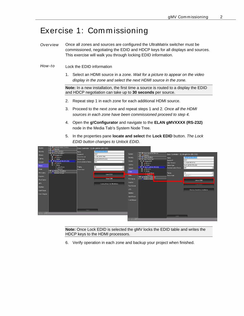
4. Open the g!Configurator and navigate to the ELAN gMVXXXX (RS-232)
node in the Media Tab’s System Node Tree.
5. In the properties pane locate and select the Lock EDID button. The Lock
EDID button changes to Unlock EDID.
Note: Once Lock EDID is selected the gMV locks the EDID table and writes the HDCP keys to the HDMI processors.
6. Verify operation in each zone and backup your project when finished.

gMV Commissioning 3
8B
Exercise 2: Replacing an HDMI Device Overview How-to
When an HDMI device is replaced the system will need to be re-commissioned. The steps below will walk you through how to re-commission a device to the gMV.
Replace an HDMI device
1. Open the g!Configurator and navigate to the ELAN gMVXXXX (RS-232)
node in the Media Tab’s System Node Tree.
2. In the properties pane locate and select the Unlock EDID button.
3. The Clear EDID button is now available. Select the Clear EDID button to erase
all EDID and HDCP table information from the gMV unit.
4. Repeat steps 1 - 6 in How-to Lock the EDID information above.
gMV Commissioning 4
Exercise 3: Factory Reset gMV Overview How-to
In some instances it may be necessary to Factory Reset the gMV unit, such as if
you move a gMV unit from one project to another. A factory reset of the gMV unit
removes all configurations previously made to the unit and restores the unit to its
factory default settings.
Factory Reset the gMV
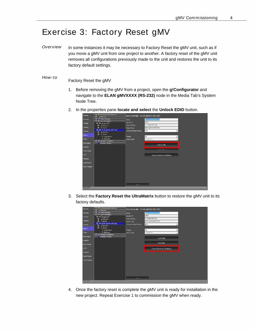
1. Before removing the gMV from a project, open the g!Configurator and
navigate to the ELAN gMVXXXX (RS-232) node in the Media Tab’s System
Node Tree.
2. In the properties pane locate and select the Unlock EDID button.
3. Select the Factory Reset the UltraMatrix button to restore the gMV unit to its
factory defaults.
4. Once the factory reset is complete the gMV unit is ready for installation in the
new project. Repeat Exercise 1 to commission the gMV when ready.

gMV Commissioning 5
Notes: _____________________________________________________________________________
_____________________________________________________________________________
_____________________________________________________________________________
_____________________________________________________________________________
_____________________________________________________________________________
_____________________________________________________________________________
_____________________________________________________________________________
_____________________________________________________________________________
_____________________________________________________________________________
_____________________________________________________________________________
_____________________________________________________________________________
_____________________________________________________________________________
_____________________________________________________________________________
_____________________________________________________________________________
_____________________________________________________________________________
_____________________________________________________________________________
_____________________________________________________________________________
_____________________________________________________________________________
_____________________________________________________________________________
_____________________________________________________________________________
_____________________________________________________________________________
_____________________________________________________________________________
_____________________________________________________________________________
_____________________________________________________________________________
_____________________________________________________________________________
_____________________________________________________________________________
_____________________________________________________________________________
_____________________________________________________________________________
_____________________________________________________________________________
_____________________________________________________________________________