enginnering | design | installation m a n u a l
TRANSCRIPT

ENGINNERING | DESIGN | INSTALLATION
M A N U A L

ENGINNERING | DESIGN | INSTALLATION 2
HELICAL PIERS INC.
TABLE OF CONTENTS ABOUT helical piers inc. ................................................................................................................................ 4
OUR PRODUCTS .................................................................................................................................... 4
APPLICATIONS ........................................................................................................................................... 5
deep foundations .................................................................................................................................. 5
earth retention ...................................................................................................................................... 6
Other Applications ................................................................................................................................ 7
INTRODUCTION ............................................................................................................................................. 9
Basic Features ....................................................................................................................................... 9
terminology ......................................................................................................................................... 10
HISTORY .............................................................................................................................................. 12
modern applications ........................................................................................................................... 12
environmental sustainability .............................................................................................................. 12
installation .................................................................................................................................................. 14
design .......................................................................................................................................................... 17
bearing capacity .................................................................................................................................. 17
technical data .............................................................................................................................................. 21
ENGINNERING | DESIGN | INSTALLATION 3
HELICAL PIERS INC.
HELICAL PIERS INC.
OUR COMPANY & OUR PRODUCTS

ENGINNERING | DESIGN | INSTALLATION 4
HELICAL PIERS INC.
ABOUT HELICAL PIERS INC. Helical Piers Inc. (HPI) personnel have an extensive background in the downhole drill tool market. In 1969, Ake
Ronnkvist developed the Inertia Welded Drill Pipe. In 1979, Mr. Ronnkvist was awarded a patent for the Inertia
Welded Sucker Rod used to power oil well pumps. He was recognized with the NGWA “Achievement in
Technology Award” in 1987.
In 2008, the team at HPI was recognized for designing and manufacturing the drill string that was used to drill
the escape shaft for the Chilean Mine Rescue. Since 2009, HPI was awarded three patents; the first being an
Inertia Welded Helical Anchor with hardened ends, second being in 2015 which was a High Tension Cable
Divider Screw-In Foundation System, and most recently, in 2018, we designed and applied for a patent on the
Hex Drive Helical Anchor (Patent Pending).
The first Helical Anchor Patent was sold as an asset of a past company that HPI staff founded and operated.
This patented product was commercially successful at the time of sale. This product has seen extreme growth
and success, which is why we have spent several years designing our new anchor. We have seen great interest
in this new design.
OUR PRODUCTS At Helical Piers Inc., we use the highest quality material, cutting edge heat treatment technology, multiple
welding processes, CNC machine centers, thread gauges, and computer assisted design tools. Each step of our
manufacturing process is closely monitored by our quality control personnel, who have a distinctive role in our
business. A history of success proves it.
In order to competitively compete in today’s growing helical anchor market, we knew we had to manufacture
a helical anchor that tests as the highest torque ratings and capacity ratings on the market. We did just that.
HPI’s newest design, the “Hex Drive Helical”, is proven to have torsion strength greater than two times the
industry standard. This new design allows for more torsional capacity due to the connection between the lead
& the extension(s) as well as the connection between the drive head & the lead or extension(s). This has given
the industry a higher bearing capacity pile in both tension and/or compression applications.
The new design only uses one bolt for connections, instead of the standard 3 bolt design. This provides quicker
connection times, leading to increased productions. With our new design, contractors can now use less piles
with quicker installation times, while still achieving the needed bearing capacities.

ENGINNERING | DESIGN | INSTALLATION 5
HELICAL PIERS INC.
APPLICATIONS Our helical piers are used for many different applications. Helical Piers Inc.’s product can support any load or
application, with a fast and efficient installation process. We have included examples of applications used
today:
DEEP FOUNDATIONS
Boardwalk Foundations Our helical piers can be used as a foundation for eco-friendly boardwalks where soil conditions are unfavorable.
The piles can be installed with portable installation equipment in order to provide minimal disturbance. Our
piles also provide increased resistance for boardwalks that are exposed to flooding and storm surges.
Bridge Foundations Helical Piers Inc. helical piles are the perfect deep foundation solution for small bridge foundations. Helical
piles are also cost-effective, and contractors and engineers prefer helical piles as they can be installed with
compact hydraulic-driven drills.
Communication Tower Foundations We have designed helical piles that have been used to support communication and transmission towers across
the country. Helical piles are preferred when mobilization is limited in remote areas, especially if soils are
difficult. This form of support for the towers is also highly preferred, as there is much less steel that is used.
Light Poles Utilizing helical piles in lieu of typical concrete piers allows for immediate installation of the light pole after the
helical pile has been installed properly as there is no waiting for concrete to cure. The helical pile is also not
susceptible to frost/freeze thaw cycle which means a stronger and longer lasting footing/foundation for the
light pole.
Residential & Commercial Foundations Our helical piles can be used for new and failing residential and commercial foundations. Our piles can be
installed in limited access locations with less installation equipment, making helical piers a great option to lift
and stabilize residential and commercial foundations that our failing. Helical piers can also be used for new
construction foundations to stabilize concrete footing or grade beams.
Solar Foundations Helical piles are preferred in solar foundations as they fight uplift created by high wind forces and frost heaving,
which causes negative friction along pile shafts.
ENGINNERING | DESIGN | INSTALLATION 6
HELICAL PIERS INC.
Decks, Porches, Gazebos, etc.
Helical piles are a very efficient alternative to traditional concrete deck footings. They are installed with
minimal turf damage because of the small equipment needed for installation. They do not require any curing
time. They provide more protection from frost and the freeze/thaw cycle than typical concrete foundations.
Cost wise, they are very similar and are often times cheaper because of the increased installation time vs the
traditional concrete piers.
Swimming Pool Foundations Helical piles provide a great alternative to traditional swimming pool foundations (timber piling, concrete
piling, etc.). Using helical piers for swimming pool foundations also eliminate mobilization costs for large
equipment and the vibrations and spoils that typically come along with traditional foundations. The installation
of the piles is quick and efficient with the ability to immediately load after installation and move on to the next
step in the pool construction.
Wind Turbines Using helical piles for wind turbines is highly preferred, as there is less concrete used, reducing cure times. In
turn, this reduces the installation time, mobilization and money.
Generator Pads
Helical piles are a great solution for providing support for a generator. They can be used to either support the
generator itself directly (meaning there will be no concrete slab underneath the generator) or, if a slab and
footings are required due to ha heavier load or poor soil conditions, they can be used to support the slab and
footings to allow for less soil correction. Also, helical piles can be installed in very close proximity to existing
buildings, features, utilities, etc. because of their non-vibratory and small equipment installation methods.
Utility Supports
Often, above ground & below ground utility lines require support due to poor soil conditions or to provide a
platform for above ground utility lines to sit on. Helical piles are a cost effective and value-added piece to the
project. They are quick and easy to install and require not concrete curing which means immediate loading of
the piles can happen. There are an endless amount of pile brackets that can be mounted to the top of the
helical pile to provide proper fastening/support for the specific utility line or structure being supported.
EARTH RETENTION
Permanent Foundation Shoring Process Helical piers are utilized as tiebacks for permanent earth retention/foundation shoring. They allow contractors
to install tiebacks faster, easier, and without any concrete/grout (unless design requires it). The helical piles
can be galvanized to provide long lasting protection & durability against corrosion in permanent applications.
ENGINNERING | DESIGN | INSTALLATION 7
HELICAL PIERS INC.
Temporary Shoring Systems Similar to the permanent earth retention utilization of helical piers, when they are used in a temporary system,
most times they are not required to be galvanized which decreases costs and the removal of the helical piers
is quick and easy and can be done with small machinery when having to work in tight spots/areas.
OTHER APPLICATIONS
Slope Stabilization Equipment Helical Piers Inc. helical piers can be used for steep slope stabilization. The piers provide anchoring resistance
to sliding forces within slopes. This earth stabilization system is fast and easy to install, requires no cure time,
uses small equipment for difficult access areas, limits materials needed, and creates no spoils.
Tiedowns Helical piers are an easy solution for a tiedown application. Like the benefits of many other applications,
installation is quick & easy, raw material cost is lower, there is no concrete cure time, and helical piers can be
installed on land or in water and maintain the same needed tiedown capacity in wither situation.
Anti-Buoyancy Helical piles are often used for anti-buoyancy as well. They are a great solution for use in high water table
applications where there is need to hold an underground tank or structure down when high water tables or
fluctuating water tables are present. They provide a long lasting, durable, cost effective, environmentally
friendly, and easy solution for these applications.
Mooring Helical piles provide easy, effective, environmentally friendly solutions for water applications. They can be used
for docks, boat lifts, anchoring points, buoys, and shoreline protection (similar to slope stabilization). They can
be installed using light equipment and they can be galvanized to protect against corrosion. They are easily
installed and easily removed for applications that require removal during the winter months if needed.
Bollards Utilizing helical piles as bollards is a great way to reduce costs compared to typical concrete encased bollards.
They can come in the same sizes as traditional bollards and can also be filled with concrete if desired. There is
no spoil removal, substantially less concrete (depending on design/capacity needed, there could be no
concrete needed), and there is no cure time. They also provide the capability to be easily moved and re-used
if needed.
Underpinning & Foundation Repair Helical piles are commonly used to aide with foundation underpinning or foundation repair. They are a non-
vibratory solution that provides adequate foundation support to either fix/level foundations or support a
foundation while excavation/work can be done underneath existing foundations. Custom & typical footing
brackets can be mounted on each helical pile to safely and properly attached the pile to the footing so work
can be done, or proper support can be added to the existing structure.

ENGINNERING | DESIGN | INSTALLATION 8
HELICAL PIERS INC.
HELICAL PIERS
& THEIR BENEFITS
ENGINNERING | DESIGN | INSTALLATION 9
HELICAL PIERS INC.
INTRODUCTION Helical piles have been used for well over 200 years. Today, there are over 50 helical pile manufacturing
companies and there are over 163 U.S. patents relating to helical piles.
Helical piles are a great solution for deep foundations from several different perspectives. From an engineering
viewpoint, they can be adapted to support many different types of structures with several different soil
conditions.
From an owner perspective, the quick installation involved with a helical pile can reduce costs. From a
contractor standpoint, they are easy to install. From the public perspective, they are one of the most innovative
and environmentally friendly deep foundation solutions available on the market today.
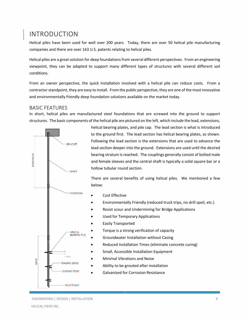
BASIC FEATURES In short, helical piles are manufactured steel foundations that are screwed into the ground to support
structures. The basic components of the helical pile are pictured on the left, which include the lead, extensions,
helical bearing plates, and pile cap. The lead section is what is introduced
to the ground first. The lead section has helical bearing plates, as shown.
Following the lead section is the extensions that are used to advance the
lead section deeper into the ground. Extensions are used until the desired
bearing stratum is reached. The couplings generally consist of bolted male
and female sleeves and the central shaft is typically a solid square bar or a
hollow tubular round section.
There are several benefits of using helical piles. We mentioned a few
below:
• Cost Effective
• Environmentally Friendly (reduced truck trips, no drill spoil, etc.)
• Resist scour and Undermining for Bridge Applications
• Used for Temporary Applications
• Easily Transported
• Torque is a strong verification of capacity
• Groundwater Installation without Casing
• Reduced Installation Times (eliminate concrete curing)
• Small, Accessible Installation Equipment
• Minimal Vibrations and Noise
• Ability to be grouted after installation
• Galvanized for Corrosion Resistance

ENGINNERING | DESIGN | INSTALLATION 10
HELICAL PIERS INC.
TERMINOLOGY Provided below is a definition of terms for helical piles.
Batter Angle: Inclination angle from vertical at which helical piles are installed; can be given as percentage,
ratio of vertical depth to horizontal run, or angle in degrees.
Bracket: Manufactured steel cap or assembly that attaches to the helical pile butt and is used to transfer loads
to new or existing foundation elements; examples include angle bracket, plate bracket, new construction
bracket.
Cohesion: Soil shear strength parameter that is constant with respect to confining pressure; basically, the
forces within soil that hold it together.
Coupling: Pinned, bolted, or welded connection of two helical piles shafts.
Down Drag: The phenomenon where soft soils surrounding a pile consolidate and produce a downward force
on the pile tending to cause additional settlement. Consolidation can be triggered by soil self-weight, periodic
changes in groundwater, placement of fill, or other surcharge loads on the ground surface.
Drive Pin: Pin used to connect a helical pile butt to a drive tool on a torque motor; typically, a high strength
smooth round pin, although any dowel of appropriate strength can be used.
Drive Tool: Adapter for transferring torque between the torque motor and the helical pile consisting of a hex
or other shape Kelly bar socket and a round or square collar sleeve.
End Bearing: Term used to describe a pile that generates most of its capacity from the pile tip such as piles
that bear directly on bedrock; essentially all helical piles with single helix are end bearing.
Flange: Pair of often-identical plates that form the main structural components of a wide flange beam, H-pile,
or I-joist; flanges are separated and held apart by the web.
Helix: Generally circular steel plate pressed in a spiral shape with uniform pitch. The helix is welded to the
shaft and used to install the helical pile in a screwing action into the ground and to transfer the load from the
shaft into the surrounding soil or rock material.
Kelly Bar: Short, typically round or hexagonal drive shaft extending from a torque motor, auger drive, or
soil/rock drill.
Lateral Load: Force acting on a helical pier in a direction that is transverse (perpendicular) to the central shaft.
Lateral Resistance: Capacity of a helical foundation system or devise to resist lateral loads.
Micropile: Small-diameter (typically 4-inch to 8-inch) drilled pile with central reinforcing steel bar surrounded
by cement grout; One of the main distinctions of micropiles compared to other types of drilled piles is the use
of smaller drilling equipment, with short mast and segmental drill stem.

ENGINNERING | DESIGN | INSTALLATION 11
HELICAL PIERS INC.
Mooring: Underwater anchoring system for securing a boat or ship. Typically consists of a helical anchor, cable
or chain, and buoy.
Pile Cap: Reinforced concrete structure of variable thickness and geometry placed over one or a group of
helical piles and used to transfer loads to a column, grade, beam, wall or other structure.
Solider Pile: Vertical pile used in earth retention.
Static Load Test: Pile load test wherein load increments are applied to a helical pile at a slow rate to simulate
static conditions. The quick test method is considered a type of static load test; loads may be applied with
deadweight blocks or by hydraulic ram; the word “static” is used to differentiate this test from cyclic, dynamic,
impulse, or statinamic load testing.
Tie-Back: Helical anchor used in earth retention with helical bearing plates located a significant distance past
the active zone of retained earth and a central shaft that extends through the active zone to a rigid wall facing;
also a term used for grouted anchors, duck-bill anchors, and deadman anchors where the bond zone is outside
of the active zone of retained earth.
Underpinning: Method of installing helical piles alongside or underneath an existing structure, connecting the
piles to the structure, and transferring support from the existing foundation elements to the helical piles; may
be associated with lifting and releveling of structures.

ENGINNERING | DESIGN | INSTALLATION 12
HELICAL PIERS INC.
HISTORY The first time a helical pile was used was in 1836 by a blind engineer named Alexander Mitchell. He steadily
lost his site from age six to twenty-one. In his spare time, he studied mechanics, mathematics, science and
building construction. An area of interest for Mitchell was how to secure structures in weak soils. This is when
Mitchell designed the first helical pile and he patented his idea in 1833. At this time, Mitchell was referring to
his patent as the “screw pile”.
In 1839, Mitchell used nine of his screw piles underneath the Maplin Sands Lighthouse. This foundation
technique was successful and was considered an extremely valuable invention for lighthouses. After this, screw
piles were used underneath several marine structures, such as piers, bridges, etc.
MODERN APPLICATIONS Helical piles have several modern applications. They are now used as/for guy wires for transmission towers,
residential construction for new foundations and decks, commercial construction foundations, boardwalks on
wetland areas, to support heavy manufacturing equipment within commercial buildings, underground
structures and foundation shoring, tie-backs, large boat lift foundations, docks, etc.
ENVIRONMENTAL SUSTAINABILITY An added benefit of helical piles is that they are environmentally sustainable. Helical piles consume less raw
material and requires few truck trips compared to other types of deep foundation applications. A helical pile
is 65 percent less raw materials by weight to construct compared to driven steel piles and 95 percent less raw
material by weight compared to drilled shafts or auger-cast piles. The table below gives an accurate
representation of the environmental benefit of using helical piles due to reduced truck trips.
FOUNDATION OPTION NUMBER OF TRIPS TO/FROM SITE TRIP DESCRIPTION
50 Helical Piles 1 2 3 total
Truck & Trailer (installation machine) Flatbed Tractor-Trailers (helical piles)
50 Drilled Shafts 14 1 1 1 17 total
Concrete Trucks Pump Trucks Flatbed Tractor Trailer (reinforcing steel) Drill Rig
50 Driven H-Piles 2 4 1 7 total
Crane Delivery & Pickup Flatbed Tractor Trailers (H-Piles) Pile-Driving Rig
ENGINNERING | DESIGN | INSTALLATION 13
HELICAL PIERS INC.
INSTALLATION
MANUAL
ENGINNERING | DESIGN | INSTALLATION 14
HELICAL PIERS INC.
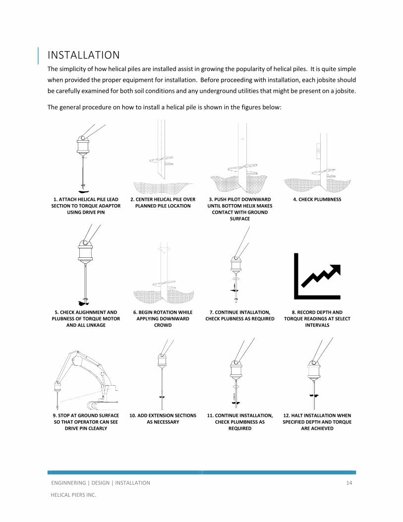
INSTALLATION The simplicity of how helical piles are installed assist in growing the popularity of helical piles. It is quite simple
when provided the proper equipment for installation. Before proceeding with installation, each jobsite should
be carefully examined for both soil conditions and any underground utilities that might be present on a jobsite.
The general procedure on how to install a helical pile is shown in the figures below:
1. ATTACH HELICAL PILE LEAD
SECTION TO TORQUE ADAPTOR USING DRIVE PIN
2. CENTER HELICAL PILE OVER PLANNED PILE LOCATION
3. PUSH PILOT DOWNWARD UNTIL BOTTOM HELIX MAKES
CONTACT WITH GROUND SURFACE
4. CHECK PLUMBNESS
5. CHECK ALIGHNMENT AND
PLUBNESS OF TORQUE MOTOR AND ALL LINKAGE
6. BEGIN ROTATION WHILE APPLYING DOWNWARD
CROWD
7. CONTINUE INTALLATION, CHECK PLUBNESS AS REQUIRED
8. RECORD DEPTH AND TORQUE READINGS AT SELECT
INTERVALS
9. STOP AT GROUND SURFACE SO THAT OPERATOR CAN SEE
DRIVE PIN CLEARLY
10. ADD EXTENSION SECTIONS AS NECESSARY
11. CONTINUE INSTALLATION, CHECK PLUMBNESS AS
REQUIRED
12. HALT INSTALLATION WHEN SPECIFIED DEPTH AND TORQUE
ARE ACHIEVED

ENGINNERING | DESIGN | INSTALLATION 15
HELICAL PIERS INC.
13. CUT SHAFT TO FINAL
ELEVATION 14. DRILL BOLT HOLES AS
NECESSARY 15. MOUNT PIER CAP 16. RECORD FINAL DEPTH,
TORQUE, AND ELEVATION

ENGINNERING | DESIGN | INSTALLATION 16
HELICAL PIERS INC.
DESIGN
MANUAL

ENGINNERING | DESIGN | INSTALLATION 17
HELICAL PIERS INC.
DESIGN There are many different factors that
go into designing and sizing the
correct pile configuration for each job.
Some of those factors include the
properties of the soil(s), installation
requirements and/or parameters,
load on the pile(s), load type on the
pile (compression, tension, shear), the
helical pile design configuration, and
other job/jobsite location factors.
BEARING CAPACITY Calculating bearing capacity is used to
determine the number and diameter
of helical bearing plates and the
strength of shaft required to support
the intended design loads. When this
is used in tandem with installation
torque measurements and load tests,
the helical pile capacity can be easily
accomplished.
The spacing of the helical plates is
extremely important, so that the
capacity is being maximized and not
wasting each helical bearing plates
capacity. If the spacing between each
helix is too close, the helixes start to
act as a group, rather than
individually. It has been determined
that the helical plates must be placed
two times or greater the average
diameter of the lower helix apart from
each other. An example of this is
provided in the figure to the right.

ENGINNERING | DESIGN | INSTALLATION 18
HELICAL PIERS INC.
INDIVIDUAL BEARING CAPACITY The individual bearing method focuses more on the bearing capacities of the helix or helices, and the
sizing/spacing that will be needed to support the given load. The factors that go into this method are: ultimate
capacity (LBS), projected helical plate area (SF), soil cohesion (LB/SF), bearing capacity factor for cohesion,
effective overburden pressure (LB/SF), bearing capacity factor for overburden, effective unit weight of the soil
(LB/CF), footing width (FT), and bearing capacity factor.
The simplified calculation of bearing pressure for a single helical plate is:
qult = An (cNc +q’Nq)
Where: qult is the ultimate bearing pressure (lbs)
An is the projected helical plate area (ft2)
c is the soil cohesion (lb/ft2)
Nc is the bearing capacity factor for cohesion
q’ is the effective overburden stress at the bearing depth (lb/ft2)
Nq is the bearing capacity factor for overburden
When calculating a helical pile that has multiple helical plates, the equation above will remain the same, but
An will include all the projected areas of each helix.
NON-COHESIVE SOIL To determine the ultimate bearing capacity in a non-cohesive or granular soil conditions, such as sand and
gravel, on a jobsite, the following equation should be used:
Qu = Σ (Ahq’Nq)
Where: Ah is the projected helix area
q is the effective overburden stress at the bearing depth (lb/ft2)
Nq is the bearing capacity factor for overburden
COHESIVE SOIL To determine the ultimate bearing capacity in a cohesive soil conditions, such as clay, on a jobsite, the following
equation should be used:
Qu = ΣAh (cNc)
Where: ΣAh is sum of the projected helix area

ENGINNERING | DESIGN | INSTALLATION 19
HELICAL PIERS INC.
c is the soil cohesion (lb/ft2)
Nc is the bearing capacity factor for cohesion
The Nc bearing capacity factor when applied to helical piles is often taken as equal to 9. The design engineer
has the option of overriding the default clay bearing capacity factor of 9.
TORQUE CORRELATION METHOD The torque correlation method (torque vs. capacity method) is another commonly used method to determine
the correct size and configuration of pile that is required. Engineers long ago discovered there was a
relationship between the torque on the helical pile during installation and capacity of that pile based on its
torque. The exact torque factor for each size pile can be determined by performing a load test(s) with each pile
in the specific soils that the helical piers will be installed in. In most cases, this either cannot or will not happen
due to project costs/time restraints. There is a common equation used to calculate torque vs. capacity:
Qu = Kt * T
Where: Kt is the torque factor
T is the torsional resistance
There are common or “average” torque factors that have been calculated and determined several years of
research from engineers. The table below shows industry standard torque factors. Factors may vary due to
soil conditions.
Industry Standard Torque Factors
Shaft Diameter 2 3/8" 2 7/8" 3 1/2" 4 1/2" 5" 5 1/2" 6 5/8" 7"
Torque Factor 9 to 10 8 to 9 7 to 8 6 to 7 6 to 7 5 to 6 4 to 5 4 to 5
Helical Piers Inc. has performed tests to determine actual torque capacities on our different sizes of helical pile
shafts which is shown below:
ADD SHAFT RATINGS
When determining pile size and configuration, be sure to consult with either Helical Piers Inc. or a licensed
engineer who has expertise and knowledge in the helical pile industry to ensure the correctly sized/configured
pile is being used on your project.

ENGINNERING | DESIGN | INSTALLATION 20
HELICAL PIERS INC.
OUR PRODUCT
MANUAL

ENGINNERING | DESIGN | INSTALLATION 21
HELICAL PIERS INC.
TECHNICAL DATA Helical Piers Inc. has assigned exclusive part numbers to each helical pier lead and extension so that our
customers can reference exactly what they are looking for. We offer two different styles of anchors: our
“standard” design and our Patent Pending “Hex Drive” helical anchor. Depending on the strength needed will
determine which design one would need.
Note: The following sizes are our standard sizes. Specialty sizes ranging up to 14” OD can be manufactured
and produced in our facility.

2 3/8 (.254 WALL) LEADS
STANDARD DESIGN
A B C
2 3/8" OD (.254 WALL) X 5' W/ 8" HELIX 8 - - 5' 23250538
2 3/8" OD (.254 WALL) X 5' W/ 10" HELIX 10 - - 5' 232505310
2 3/8" OD (.254 WALL) X 5' W/ 12" HELIX 12 - - 5' 232505312
2 3/8" OD (.254 WALL) X 5' W/ 14" HELIX 14 - - 5' 232505314
2 3/8" OD (.254 WALL) X 5' W/ 8-10" HELIX 8 10 - 5' 2325053810
2 3/8" OD (.254 WALL) X 5' W/ 10-12" HELIX 10 12 - 5' 23250531012
2 3/8" OD (.254 WALL) X 5' W/ 12-14" HELIX 12 14 - 5' 23250531214
2 3/8" OD (.254 WALL) X 7' W/ 8" HELIX 8 - - 7' 23250738
2 3/8" OD (.254 WALL) X 7' W/ 10" HELIX 10 - - 7' 232507310
2 3/8" OD (.254 WALL) X 7' W/ 12" HELIX 12 - - 7' 232507312
2 3/8" OD (.254 WALL) X 7' W/ 14" HELIX 14 - - 7' 232507314
2 3/8" OD (.254 WALL) X 7' W/ 8-10" HELIX 8 10 - 7' 2325073810
2 3/8" OD (.254 WALL) X 7' W/ 10-12" HELIX 10 12 - 7' 23250731012
2 3/8" OD (.254 WALL) X 7' W/ 12-14" HELIX 12 14 - 7' 23250731214
2 3/8" OD (.254 WALL) X 7' W/ 8-10-12" HELIX 8 10 12 7' 232507381012
2 3/8" OD (.254 WALL) X 7' W/ 10-12-14" HELIX 10 12 14 7' 2325073101214
2 3/8" OD (.254 WALL) X 10' W/ 8" HELIX 8 - - 10' 23251038
2 3/8" OD (.254 WALL) X 10' W/ 10" HELIX 10 - - 10' 232510310
2 3/8" OD (.254 WALL) X 10' W/ 12" HELIX 12 - - 10' 232510312
2 3/8" OD (.254 WALL) X 10' W/ 14" HELIX 14 - - 10' 232510314
2 3/8" OD (.254 WALL) X 10' W/ 8-10" HELIX 8 10 - 10' 2325103810
2 3/8" OD (.254 WALL) X 10' W/ 10-12" HELIX 10 12 - 10' 23251031012
2 3/8" OD (.254 WALL) X 10' W/ 12-14" HELIX 12 14 - 10' 23251031214
2 3/8" OD (.254 WALL) X 10' W/ 8-10-12" HELIX 8 10 12 10' 232510381012
2 3/8" OD (.254 WALL) X 10' W/ 10-12-14" HELIX 10 12 14 10' 2325103101214
PLATE DIAMETERLENGTH PART NUMBERPRODUCT DESCRIPTION

2 3/8 (.254 WALL) LEADS
HEX DESIGN
A B C
2 3/8" OD (.254 WALL) X 5' W/ 8" HELIX 8 - - 5' H23250538
2 3/8" OD (.254 WALL) X 5' W/ 10" HELIX 10 - - 5' H232505310
2 3/8" OD (.254 WALL) X 5' W/ 12" HELIX 12 - - 5' H232505312
2 3/8" OD (.254 WALL) X 5' W/ 14" HELIX 14 - - 5' H232505314
2 3/8" OD (.254 WALL) X 5' W/ 8-10" HELIX 8 10 - 5' H2325053810
2 3/8" OD (.254 WALL) X 5' W/ 10-12" HELIX 10 12 - 5' H23250531012
2 3/8" OD (.254 WALL) X 5' W/ 12-14" HELIX 12 14 - 5' H23250531214
2 3/8" OD (.254 WALL) X 7' W/ 8" HELIX 8 - - 7' H23250738
2 3/8" OD (.254 WALL) X 7' W/ 10" HELIX 10 - - 7' H232507310
2 3/8" OD (.254 WALL) X 7' W/ 12" HELIX 12 - - 7' H232507312
2 3/8" OD (.254 WALL) X 7' W/ 14" HELIX 14 - - 7' H232507314
2 3/8" OD (.254 WALL) X 7' W/ 8-10" HELIX 8 10 - 7' H2325073810
2 3/8" OD (.254 WALL) X 7' W/ 10-12" HELIX 10 12 - 7' H23250731012
2 3/8" OD (.254 WALL) X 7' W/ 12-14" HELIX 12 14 - 7' H23250731214
2 3/8" OD (.254 WALL) X 7' W/ 8-10-12" HELIX 8 10 12 7' H232507381012
2 3/8" OD (.254 WALL) X 7' W/ 10-12-14" HELIX 10 12 14 7' H2325073101214
2 3/8" OD (.254 WALL) X 10' W/ 8" HELIX 8 - - 10' H23251038
2 3/8" OD (.254 WALL) X 10' W/ 10" HELIX 10 - - 10' H232510310
2 3/8" OD (.254 WALL) X 10' W/ 12" HELIX 12 - - 10' H232510312
2 3/8" OD (.254 WALL) X 10' W/ 14" HELIX 14 - - 10' H232510314
2 3/8" OD (.254 WALL) X 10' W/ 8-10" HELIX 8 10 - 10' H2325103810
2 3/8" OD (.254 WALL) X 10' W/ 10-12" HELIX 10 12 - 10' H23251031012
2 3/8" OD (.254 WALL) X 10' W/ 12-14" HELIX 12 14 - 10' H23251031214
2 3/8" OD (.254 WALL) X 10' W/ 8-10-12" HELIX 8 10 12 10' H232510381012
2 3/8" OD (.254 WALL) X 10' W/ 10-12-14" HELIX 10 12 14 10' H2325103101214
PLATE DIAMETERLENGTH PART NUMBERPRODUCT DESCRIPTION

2 7/8 (.217 WALL) LEADS
STANDARD DESIGN
A B C
2 7/8" OD (.217 WALL) X 5' W/ 8" HELIX 8 - - 5' 28210538
2 7/8" OD (.217 WALL) X 5' W/ 10" HELIX 10 - - 5' 282105310
2 7/8" OD (.217 WALL) X 5' W/ 12" HELIX 12 - - 5' 282105312
2 7/8" OD (.217 WALL) X 5' W/ 14" HELIX 14 - - 5' 282105314
2 7/8" OD (.217 WALL) X 5' W/ 8-10" HELIX 8 10 - 5' 2821053810
2 7/8" OD (.217 WALL) X 5' W/ 10-12" HELIX 10 12 - 5' 28210531012
2 7/8" OD (.217 WALL) X 5' W/ 12-14" HELIX 12 14 - 5' 28210531214
2 7/8" OD (.217 WALL) X 7' W/ 8" HELIX 8 - - 7' 28210738
2 7/8" OD (.217 WALL) X 7' W/ 10" HELIX 10 - - 7' 282107310
2 7/8" OD (.217 WALL) X 7' W/ 12" HELIX 12 - - 7' 282107312
2 7/8" OD (.217 WALL) X 7' W/ 14" HELIX 14 - - 7' 282107314
2 7/8" OD (.217 WALL) X 7' W/ 8-10" HELIX 8 10 - 7' 2821073810
2 7/8" OD (.217 WALL) X 7' W/ 10-12" HELIX 10 12 - 7' 28210731012
2 7/8" OD (.217 WALL) X 7' W/ 12-14" HELIX 12 14 - 7' 28210731214
2 7/8" OD (.217 WALL) X 7' W/ 8-10-12" HELIX 8 10 12 7' 282107381012
2 7/8" OD (.217 WALL) X 7' W/ 10-12-14" HELIX 10 12 14 7' 2821073101214
2 7/8" OD (.217 WALL) X 10' W/ 8" HELIX 8 - - 10' 28211038
2 7/8" OD (.217 WALL) X 10' W/ 10" HELIX 10 - - 10' 282110310
2 7/8" OD (.217 WALL) X 10' W/ 12" HELIX 12 - - 10' 282110312
2 7/8" OD (.217 WALL) X 10' W/ 14" HELIX 14 - - 10' 282110314
2 7/8" OD (.217 WALL) X 10' W/ 8-10" HELIX 8 10 - 10' 2821103810
2 7/8" OD (.217 WALL) X 10' W/ 10-12" HELIX 10 12 - 10' 28211031012
2 7/8" OD (.217 WALL) X 10' W/ 12-14" HELIX 12 14 - 10' 28211031214
2 7/8" OD (.217 WALL) X 10' W/ 8-10-12" HELIX 8 10 12 10' 282110381012
2 7/8" OD (.217 WALL) X 10' W/ 10-12-14" HELIX 10 12 14 10' 2821103101214
PLATE DIAMETERLENGTH PART NUMBERPRODUCT DESCRIPTION

2 7/8 (.217 WALL) LEADS
HEX DESIGN
A B C
2 7/8" OD (.217 WALL) X 5' W/ 8" HELIX 8 - - 5' H28210538
2 7/8" OD (.217 WALL) X 5' W/ 10" HELIX 10 - - 5' H282105310
2 7/8" OD (.217 WALL) X 5' W/ 12" HELIX 12 - - 5' H282105312
2 7/8" OD (.217 WALL) X 5' W/ 14" HELIX 14 - - 5' H282105314
2 7/8" OD (.217 WALL) X 5' W/ 8-10" HELIX 8 10 - 5' H2821053810
2 7/8" OD (.217 WALL) X 5' W/ 10-12" HELIX 10 12 - 5' H28210531012
2 7/8" OD (.217 WALL) X 5' W/ 12-14" HELIX 12 14 - 5' H28210531214
2 7/8" OD (.217 WALL) X 7' W/ 8" HELIX 8 - - 7' H28210738
2 7/8" OD (.217 WALL) X 7' W/ 10" HELIX 10 - - 7' H282107310
2 7/8" OD (.217 WALL) X 7' W/ 12" HELIX 12 - - 7' H282107312
2 7/8" OD (.217 WALL) X 7' W/ 14" HELIX 14 - - 7' H282107314
2 7/8" OD (.217 WALL) X 7' W/ 8-10" HELIX 8 10 - 7' H2821073810
2 7/8" OD (.217 WALL) X 7' W/ 10-12" HELIX 10 12 - 7' H28210731012
2 7/8" OD (.217 WALL) X 7' W/ 12-14" HELIX 12 14 - 7' H28210731214
2 7/8" OD (.217 WALL) X 7' W/ 8-10-12" HELIX 8 10 12 7' H282107381012
2 7/8" OD (.217 WALL) X 7' W/ 10-12-14" HELIX 10 12 14 7' H2821073101214
2 7/8" OD (.217 WALL) X 10' W/ 8" HELIX 8 - - 10' H28211038
2 7/8" OD (.217 WALL) X 10' W/ 10" HELIX 10 - - 10' H282110310
2 7/8" OD (.217 WALL) X 10' W/ 12" HELIX 12 - - 10' H282110312
2 7/8" OD (.217 WALL) X 10' W/ 14" HELIX 14 - - 10' H282110314
2 7/8" OD (.217 WALL) X 10' W/ 8-10" HELIX 8 10 - 10' H2821103810
2 7/8" OD (.217 WALL) X 10' W/ 10-12" HELIX 10 12 - 10' H28211031012
2 7/8" OD (.217 WALL) X 10' W/ 12-14" HELIX 12 14 - 10' H28211031214
2 7/8" OD (.217 WALL) X 10' W/ 8-10-12" HELIX 8 10 12 10' H282110381012
2 7/8" OD (.217 WALL) X 10' W/ 10-12-14" HELIX 10 12 14 10' H2821103101214
PLATE DIAMETERLENGTH PART NUMBERPRODUCT DESCRIPTION

2 7/8 (.276 WALL) LEADS
STANDARD DESIGN
A B C
2 7/8" OD (.276 WALL) X 5' W/ 8" HELIX 8 - - 5' 28270538
2 7/8" OD (.276 WALL) X 5' W/ 10" HELIX 10 - - 5' 282705310
2 7/8" OD (.276 WALL) X 5' W/ 12" HELIX 12 - - 5' 282705312
2 7/8" OD (.276 WALL) X 5' W/ 14" HELIX 14 - - 5' 282705314
2 7/8" OD (.276 WALL) X 5' W/ 8-10" HELIX 8 10 - 5' 2827053810
2 7/8" OD (.276 WALL) X 5' W/ 10-12" HELIX 10 12 - 5' 28270531012
2 7/8" OD (.276 WALL) X 5' W/ 12-14" HELIX 12 14 - 5' 28270531214
2 7/8" OD (.276 WALL) X 7' W/ 8" HELIX 8 - - 7' 28270738
2 7/8" OD (.276 WALL) X 7' W/ 10" HELIX 10 - - 7' 282707310
2 7/8" OD (.276 WALL) X 7' W/ 12" HELIX 12 - - 7' 282707312
2 7/8" OD (.276 WALL) X 7' W/ 14" HELIX 14 - - 7' 282707314
2 7/8" OD (.276 WALL) X 7' W/ 8-10" HELIX 8 10 - 7' 2827073810
2 7/8" OD (.276 WALL) X 7' W/ 10-12" HELIX 10 12 - 7' 28270731012
2 7/8" OD (.276 WALL) X 7' W/ 12-14" HELIX 12 14 - 7' 28270731214
2 7/8" OD (.276 WALL) X 7' W/ 8-10-12" HELIX 8 10 12 7' 282730781012
2 7/8" OD (.276 WALL) X 7' W/ 10-12-14" HELIX 10 12 14 7' 2827307101214
2 7/8" OD (.276 WALL) X 10' W/ 8" HELIX 8 - - 10' 28271038
2 7/8" OD (.276 WALL) X 10' W/ 10" HELIX 10 - - 10' 282710310
2 7/8" OD (.276 WALL) X 10' W/ 12" HELIX 12 - - 10' 282710312
2 7/8" OD (.276 WALL) X 10' W/ 14" HELIX 14 - - 10' 282710314
2 7/8" OD (.276 WALL) X 10' W/ 8-10" HELIX 8 10 - 10' 2827103810
2 7/8" OD (.276 WALL) X 10' W/ 10-12" HELIX 10 12 - 10' 28271031012
2 7/8" OD (.276 WALL) X 10' W/ 12-14" HELIX 12 14 - 10' 28271031214
2 7/8" OD (.276 WALL) X 10' W/ 8-10-12" HELIX 8 10 12 10' 282710381012
2 7/8" OD (.276 WALL) X 10' W/ 10-12-14" HELIX 10 12 14 10' 2827103101214
PLATE DIAMETERLENGTH PART NUMBERPRODUCT DESCRIPTION

2 7/8 (.276 WALL) LEADS
HEX DESIGN
A B C
2 7/8" OD (.276 WALL) X 5' W/ 8" HELIX 8 - - 5' H28270538
2 7/8" OD (.276 WALL) X 5' W/ 10" HELIX 10 - - 5' H282705310
2 7/8" OD (.276 WALL) X 5' W/ 12" HELIX 12 - - 5' H282705312
2 7/8" OD (.276 WALL) X 5' W/ 14" HELIX 14 - - 5' H282705314
2 7/8" OD (.276 WALL) X 5' W/ 8-10" HELIX 8 10 - 5' H2827053810
2 7/8" OD (.276 WALL) X 5' W/ 10-12" HELIX 10 12 - 5' H28270531012
2 7/8" OD (.276 WALL) X 5' W/ 12-14" HELIX 12 14 - 5' H28270531214
2 7/8" OD (.276 WALL) X 7' W/ 8" HELIX 8 - - 7' H28270738
2 7/8" OD (.276 WALL) X 7' W/ 10" HELIX 10 - - 7' H282707310
2 7/8" OD (.276 WALL) X 7' W/ 12" HELIX 12 - - 7' H282707312
2 7/8" OD (.276 WALL) X 7' W/ 14" HELIX 14 - - 7' H282707314
2 7/8" OD (.276 WALL) X 7' W/ 8-10" HELIX 8 10 - 7' H2827073810
2 7/8" OD (.276 WALL) X 7' W/ 10-12" HELIX 10 12 - 7' H28270731012
2 7/8" OD (.276 WALL) X 7' W/ 12-14" HELIX 12 14 - 7' H28270731214
2 7/8" OD (.276 WALL) X 7' W/ 8-10-12" HELIX 8 10 12 7' H282730781012
2 7/8" OD (.276 WALL) X 7' W/ 10-12-14" HELIX 10 12 14 7' H2827307101214
2 7/8" OD (.276 WALL) X 10' W/ 8" HELIX 8 - - 10' H28271038
2 7/8" OD (.276 WALL) X 10' W/ 10" HELIX 10 - - 10' H282710310
2 7/8" OD (.276 WALL) X 10' W/ 12" HELIX 12 - - 10' H282710312
2 7/8" OD (.276 WALL) X 10' W/ 14" HELIX 14 - - 10' H282710314
2 7/8" OD (.276 WALL) X 10' W/ 8-10" HELIX 8 10 - 10' H2827103810
2 7/8" OD (.276 WALL) X 10' W/ 10-12" HELIX 10 12 - 10' H28271031012
2 7/8" OD (.276 WALL) X 10' W/ 12-14" HELIX 12 14 - 10' H28271031214
2 7/8" OD (.276 WALL) X 10' W/ 8-10-12" HELIX 8 10 12 10' H282710381012
2 7/8" OD (.276 WALL) X 10' W/ 10-12-14" HELIX 10 12 14 10' H2827103101214
PLATE DIAMETERLENGTH PART NUMBERPRODUCT DESCRIPTION

3 1/2 (.254 WALL) LEADS
STANDARD DESIGN
A B C
3 1/2" OD (.254 WALL) X 5' W/ 10" HELIX 10 - - 5' 352505310
3 1/2" OD (.254 WALL) X 5' W/ 12" HELIX 12 - - 5' 352505312
3 1/2" OD (.254 WALL) X 5' W/ 14" HELIX 14 - - 5' 352505314
3 1/2" OD (.254 WALL) X 5' W/ 10-12" HELIX 10 12 - 5' 35250531012
3 1/2" OD (.254 WALL) X 5' W/ 12-14" HELIX 12 14 - 5' 35250531214
3 1/2" OD (.254 WALL) X 7' W/ 10" HELIX 10 - - 7' 352507310
3 1/2" OD (.254 WALL) X 7' W/ 12" HELIX 12 - - 7' 352507312
3 1/2" OD (.254 WALL) X 7' W/ 14" HELIX 14 - - 7' 352507314
3 1/2" OD (.254 WALL) X 7' W/ 10-12" HELIX 10 12 - 7' 35250731012
3 1/2" OD (.254 WALL) X 7' W/ 12-14" HELIX 12 14 - 7' 35250731214
3 1/2" OD (.254 WALL) X 7' W/ 10-12-14" HELIX 10 12 14 7' 3525073101214
3 1/2" OD (.254 WALL) X 10' W/ 10" HELIX 10 - - 10' 352510310
3 1/2" OD (.254 WALL) X 10' W/ 12" HELIX 12 - - 10' 352510312
3 1/2" OD (.254 WALL) X 10' W/ 14" HELIX 14 - - 10' 352510314
3 1/2" OD (.254 WALL) X 10' W/ 10-12" HELIX 10 12 - 10' 35251031012
3 1/2" OD (.254 WALL) X 10' W/ 12-14" HELIX 12 14 - 10' 35251031214
3 1/2" OD (.254 WALL) X 10' W/ 10-12-14" HELIX 10 12 14 10' 3525103101214
PLATE DIAMETERLENGTH PART NUMBERPRODUCT DESCRIPTION

3 1/2 (.254 WALL) LEADS
HEX DESIGN
A B C
3 1/2" OD (.254 WALL) X 5' W/ 10" HELIX 10 - - 5' H352505310
3 1/2" OD (.254 WALL) X 5' W/ 12" HELIX 12 - - 5' H352505312
3 1/2" OD (.254 WALL) X 5' W/ 14" HELIX 14 - - 5' H352505314
3 1/2" OD (.254 WALL) X 5' W/ 10-12" HELIX 10 12 - 5' H35250531012
3 1/2" OD (.254 WALL) X 5' W/ 12-14" HELIX 12 14 - 5' H35250531214
3 1/2" OD (.254 WALL) X 7' W/ 10" HELIX 10 - - 7' H352507310
3 1/2" OD (.254 WALL) X 7' W/ 12" HELIX 12 - - 7' H352507312
3 1/2" OD (.254 WALL) X 7' W/ 14" HELIX 14 - - 7' H352507314
3 1/2" OD (.254 WALL) X 7' W/ 10-12" HELIX 10 12 - 7' H35250731012
3 1/2" OD (.254 WALL) X 7' W/ 12-14" HELIX 12 14 - 7' H35250731214
3 1/2" OD (.254 WALL) X 7' W/ 10-12-14" HELIX 10 12 14 7' H3525073101214
3 1/2" OD (.254 WALL) X 10' W/ 10" HELIX 10 - - 10' H352510310
3 1/2" OD (.254 WALL) X 10' W/ 12" HELIX 12 - - 10' H352510312
3 1/2" OD (.254 WALL) X 10' W/ 14" HELIX 14 - - 10' H352510314
3 1/2" OD (.254 WALL) X 10' W/ 10-12" HELIX 10 12 - 10' H35251031012
3 1/2" OD (.254 WALL) X 10' W/ 12-14" HELIX 12 14 - 10' H35251031214
3 1/2" OD (.254 WALL) X 10' W/ 10-12-14" HELIX 10 12 14 10' H3525103101214
PLATE DIAMETERLENGTH PART NUMBERPRODUCT DESCRIPTION

3 1/2 (.368 WALL) LEADS
STANDARD DESIGN
A B C
3 1/2" OD (.368 WALL) X 5' W/ 10" HELIX 10 - - 5' 353605310
3 1/2" OD (.368 WALL) X 5' W/ 12" HELIX 12 - - 5' 353605312
3 1/2" OD (.368 WALL) X 5' W/ 14" HELIX 14 - - 5' 353605314
3 1/2" OD (.368 WALL) X 5' W/ 10-12" HELIX 10 12 - 5' 35360531012
3 1/2" OD (.368 WALL) X 5' W/ 12-14" HELIX 12 14 - 5' 35360531214
3 1/2" OD (.368 WALL) X 7' W/ 10" HELIX 10 - - 7' 353607310
3 1/2" OD (.368 WALL) X 7' W/ 12" HELIX 12 - - 7' 353607312
3 1/2" OD (.368 WALL) X 7' W/ 14" HELIX 14 - - 7' 353607314
3 1/2" OD (.368 WALL) X 7' W/ 10-12" HELIX 10 12 - 7' 35360731012
3 1/2" OD (.368 WALL) X 7' W/ 12-14" HELIX 12 14 - 7' 35360731214
3 1/2" OD (.368 WALL) X 7' W/ 10-12-14" HELIX 10 12 14 7' 3536073101214
3 1/2" OD (.368 WALL) X 10' W/ 10" HELIX 10 - - 10' 353610310
3 1/2" OD (.368 WALL) X 10' W/ 12" HELIX 12 - - 10' 353610312
3 1/2" OD (.368 WALL) X 10' W/ 14" HELIX 14 - - 10' 353610314
3 1/2" OD (.368 WALL) X 10' W/ 10-12" HELIX 10 12 - 10' 35361031012
3 1/2" OD (.368 WALL) X 10' W/ 12-14" HELIX 12 14 - 10' 35361031214
3 1/2" OD (.368 WALL) X 10' W/ 10-12-14" HELIX 10 12 14 10' 3536103101214
PLATE DIAMETERLENGTH PART NUMBERPRODUCT DESCRIPTION

3 1/2 (.368 WALL) LEADS
HEX DESIGN
A B C
3 1/2" OD (.368 WALL) X 5' W/ 10" HELIX 10 - - 5' H353605310
3 1/2" OD (.368 WALL) X 5' W/ 12" HELIX 12 - - 5' H353605312
3 1/2" OD (.368 WALL) X 5' W/ 14" HELIX 14 - - 5' H353605314
3 1/2" OD (.368 WALL) X 5' W/ 10-12" HELIX 10 12 - 5' H35360531012
3 1/2" OD (.368 WALL) X 5' W/ 12-14" HELIX 12 14 - 5' H35360531214
3 1/2" OD (.368 WALL) X 7' W/ 10" HELIX 10 - - 7' H353607310
3 1/2" OD (.368 WALL) X 7' W/ 12" HELIX 12 - - 7' H353607312
3 1/2" OD (.368 WALL) X 7' W/ 14" HELIX 14 - - 7' H353607314
3 1/2" OD (.368 WALL) X 7' W/ 10-12" HELIX 10 12 - 7' H35360731012
3 1/2" OD (.368 WALL) X 7' W/ 12-14" HELIX 12 14 - 7' H35360731214
3 1/2" OD (.368 WALL) X 7' W/ 10-12-14" HELIX 10 12 14 7' H3536073101214
3 1/2" OD (.368 WALL) X 10' W/ 10" HELIX 10 - - 10' H353610310
3 1/2" OD (.368 WALL) X 10' W/ 12" HELIX 12 - - 10' H353610312
3 1/2" OD (.368 WALL) X 10' W/ 14" HELIX 14 - - 10' H353610314
3 1/2" OD (.368 WALL) X 10' W/ 10-12" HELIX 10 12 - 10' H35361031012
3 1/2" OD (.368 WALL) X 10' W/ 12-14" HELIX 12 14 - 10' H35361031214
3 1/2" OD (.368 WALL) X 10' W/ 10-12-14" HELIX 10 12 14 10' H3536103101214
PLATE DIAMETERLENGTH PART NUMBERPRODUCT DESCRIPTION

4 1/2 (.250 WALL) LEADS
STANDARD DESIGN
A B C
4 1/2" OD (.250 WALL) X 5' W/ 10" HELIX 10 - - 5' 452505310
4 1/2" OD (.250 WALL) X 5' W/ 12" HELIX 12 - - 5' 452505312
4 1/2" OD (.250 WALL) X 5' W/ 14" HELIX 14 - - 5' 452505314
4 1/2" OD (.250 WALL) X 5' W/ 10-12" HELIX 10 12 - 5' 45250531012
4 1/2" OD (.250 WALL) X 5' W/ 12-14" HELIX 12 14 - 5' 45250531214
4 1/2" OD (.250 WALL) X 7' W/ 10" HELIX 10 - - 7' 452507310
4 1/2" OD (.250 WALL) X 7' W/ 12" HELIX 12 - - 7' 452507312
4 1/2" OD (.250 WALL) X 7' W/ 14" HELIX 14 - - 7' 452507314
4 1/2" OD (.250 WALL) X 7' W/ 10-12" HELIX 10 12 - 7' 45250731012
4 1/2" OD (.250 WALL) X 7' W/ 12-14" HELIX 12 14 - 7' 45250731214
4 1/2" OD (.250 WALL) X 7' W/ 10-12-14" HELIX 10 12 14 7' 4525073101214
4 1/2" OD (.250 WALL) X 10' W/ 10" HELIX 10 - - 10' 452510310
4 1/2" OD (.250 WALL) X 10' W/ 12" HELIX 12 - - 10' 452510312
4 1/2" OD (.250 WALL) X 10' W/ 14" HELIX 14 - - 10' 452510314
4 1/2" OD (.250 WALL) X 10' W/ 10-12" HELIX 10 12 - 10' 45251031012
4 1/2" OD (.250 WALL) X 10' W/ 12-14" HELIX 12 14 - 10' 45251031214
4 1/2" OD (.250 WALL) X 10' W/ 10-12-14" HELIX 10 12 14 10' 4525103101214
PLATE DIAMETERLENGTH PART NUMBERPRODUCT DESCRIPTION

4 1/2 (.250 WALL) LEADS
HEX DESIGN
A B C
4 1/2" OD (.250 WALL) X 5' W/ 10" HELIX 10 - - 5' H452505310
4 1/2" OD (.250 WALL) X 5' W/ 12" HELIX 12 - - 5' H452505312
4 1/2" OD (.250 WALL) X 5' W/ 14" HELIX 14 - - 5' H452505314
4 1/2" OD (.250 WALL) X 5' W/ 10-12" HELIX 10 12 - 5' H45250531012
4 1/2" OD (.250 WALL) X 5' W/ 12-14" HELIX 12 14 - 5' H45250531214
4 1/2" OD (.250 WALL) X 7' W/ 10" HELIX 10 - - 7' H452507310
4 1/2" OD (.250 WALL) X 7' W/ 12" HELIX 12 - - 7' H452507312
4 1/2" OD (.250 WALL) X 7' W/ 14" HELIX 14 - - 7' H452507314
4 1/2" OD (.250 WALL) X 7' W/ 10-12" HELIX 10 12 - 7' H45250731012
4 1/2" OD (.250 WALL) X 7' W/ 12-14" HELIX 12 14 - 7' H45250731214
4 1/2" OD (.250 WALL) X 7' W/ 10-12-14" HELIX 10 12 14 7' H4525073101214
4 1/2" OD (.250 WALL) X 10' W/ 10" HELIX 10 - - 10' H452510310
4 1/2" OD (.250 WALL) X 10' W/ 12" HELIX 12 - - 10' H452510312
4 1/2" OD (.250 WALL) X 10' W/ 14" HELIX 14 - - 10' H452510314
4 1/2" OD (.250 WALL) X 10' W/ 10-12" HELIX 10 12 - 10' H45251031012
4 1/2" OD (.250 WALL) X 10' W/ 12-14" HELIX 12 14 - 10' H45251031214
4 1/2" OD (.250 WALL) X 10' W/ 10-12-14" HELIX 10 12 14 10' H4525103101214
PLATE DIAMETERLENGTH PART NUMBERPRODUCT DESCRIPTION

4 1/2 (.337 WALL) LEADS
STANDARD DESIGN
A B C
4 1/2" OD (.337 WALL) X 5' W/ 10" HELIX 10 - - 5' 453305510
4 1/2" OD (.337 WALL) X 5' W/ 12" HELIX 12 - - 5' 453305512
4 1/2" OD (.337 WALL) X 5' W/ 14" HELIX 14 - - 5' 453305514
4 1/2" OD (.337 WALL) X 5' W/ 10-12" HELIX 10 12 - 5' 45330551012
4 1/2" OD (.337 WALL) X 5' W/ 12-14" HELIX 12 14 - 5' 45330551214
4 1/2" OD (.337 WALL) X 7' W/ 10" HELIX 10 - - 7' 453307510
4 1/2" OD (.337 WALL) X 7' W/ 12" HELIX 12 - - 7' 453307512
4 1/2" OD (.337 WALL) X 7' W/ 14" HELIX 14 - - 7' 453307514
4 1/2" OD (.337 WALL) X 7' W/ 10-12" HELIX 10 12 - 7' 45330751012
4 1/2" OD (.337 WALL) X 7' W/ 12-14" HELIX 12 14 - 7' 45330751214
4 1/2" OD (.337 WALL) X 7' W/ 10-12-14" HELIX 10 12 14 7' 4533075101214
4 1/2" OD (.337 WALL) X 10' W/ 10" HELIX 10 - - 10' 453310510
4 1/2" OD (.337 WALL) X 10' W/ 12" HELIX 12 - - 10' 453310512
4 1/2" OD (.337 WALL) X 10' W/ 14" HELIX 14 - - 10' 453310514
4 1/2" OD (.337 WALL) X 10' W/ 10-12" HELIX 10 12 - 10' 45331051012
4 1/2" OD (.337 WALL) X 10' W/ 12-14" HELIX 12 14 - 10' 45331051214
4 1/2" OD (.337 WALL) X 10' W/ 10-12-14" HELIX 10 12 14 10' 4523305101214
PLATE DIAMETERLENGTH PART NUMBERPRODUCT DESCRIPTION

4 1/2 (.250 WALL) LEADS
HEX DESIGN
A B C
4 1/2" OD (.337 WALL) X 5' W/ 10" HELIX 10 - - 5' H453305310
4 1/2" OD (.337 WALL) X 5' W/ 12" HELIX 12 - - 5' H453305312
4 1/2" OD (.337 WALL) X 5' W/ 14" HELIX 14 - - 5' H453305314
4 1/2" OD (.337 WALL) X 5' W/ 10-12" HELIX 10 12 - 5' H45330531012
4 1/2" OD (.337 WALL) X 5' W/ 12-14" HELIX 12 14 - 5' H45330531214
4 1/2" OD (.337 WALL) X 7' W/ 10" HELIX 10 - - 7' H453307310
4 1/2" OD (.337 WALL) X 7' W/ 12" HELIX 12 - - 7' H453307312
4 1/2" OD (.337 WALL) X 7' W/ 14" HELIX 14 - - 7' H453307314
4 1/2" OD (.337 WALL) X 7' W/ 10-12" HELIX 10 12 - 7' H45330731012
4 1/2" OD (.337 WALL) X 7' W/ 12-14" HELIX 12 14 - 7' H45330731214
4 1/2" OD (.337 WALL) X 7' W/ 10-12-14" HELIX 10 12 14 7' H4533073101214
4 1/2" OD (.337 WALL) X 10' W/ 10" HELIX 10 - - 10' H453310310
4 1/2" OD (.337 WALL) X 10' W/ 12" HELIX 12 - - 10' H453310312
4 1/2" OD (.337 WALL) X 10' W/ 14" HELIX 14 - - 10' H453310314
4 1/2" OD (.337 WALL) X 10' W/ 10-12" HELIX 10 12 - 10' H45331031012
4 1/2" OD (.337 WALL) X 10' W/ 12-14" HELIX 12 14 - 10' H45331031214
4 1/2" OD (.337 WALL) X 10' W/ 10-12-14" HELIX 10 12 14 10' H4523303101214
PLATE DIAMETERLENGTH PART NUMBERPRODUCT DESCRIPTION

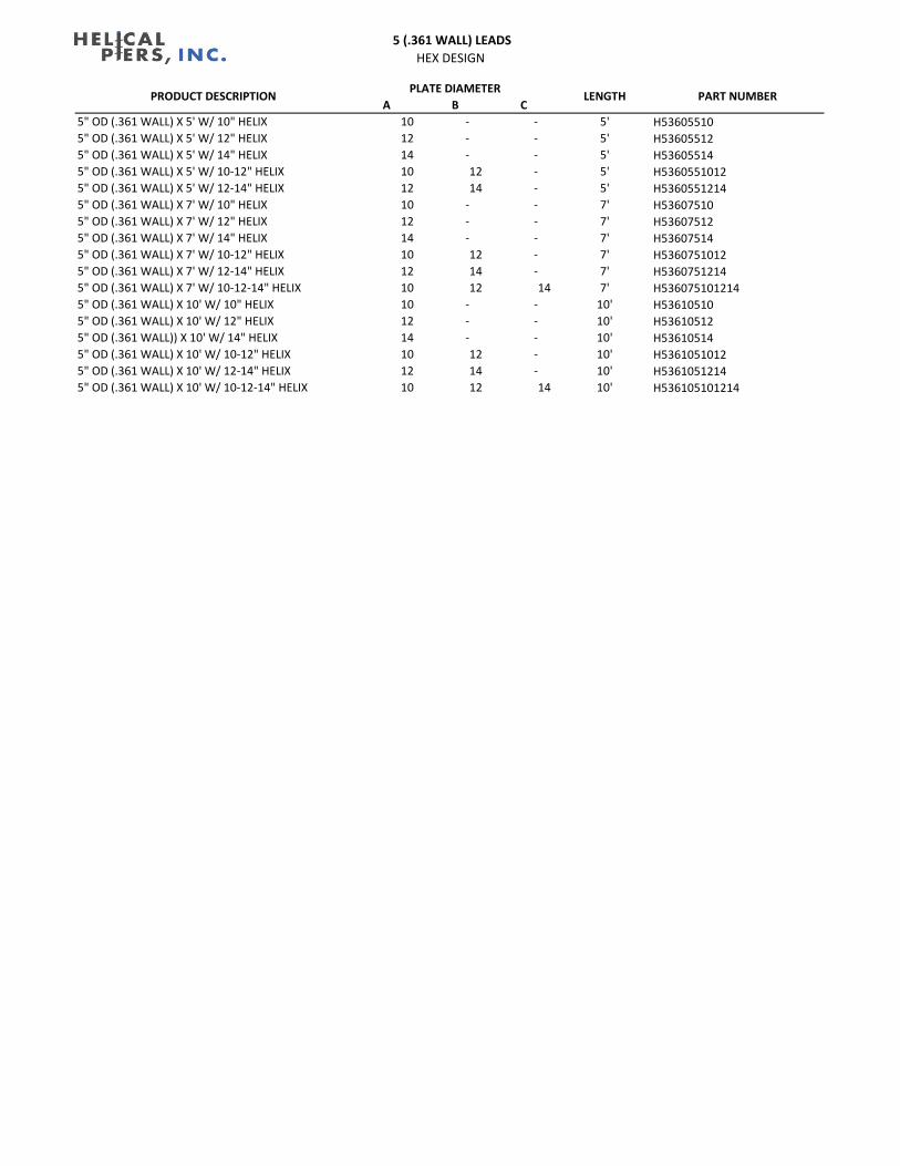
5 (.361 WALL) LEADS
STANDARD DESIGN
A B C
5" OD (.361 WALL) X 5' W/ 10" HELIX 10 - - 5' 53605510
5" OD (.361 WALL) X 5' W/ 12" HELIX 12 - - 5' 53605512
5" OD (.361 WALL) X 5' W/ 14" HELIX 14 - - 5' 53605514
5" OD (.361 WALL) X 5' W/ 10-12" HELIX 10 12 - 5' 5360551012
5" OD (.361 WALL) X 5' W/ 12-14" HELIX 12 14 - 5' 5360551214
5" OD (.361 WALL) X 7' W/ 10" HELIX 10 - - 7' 53607510
5" OD (.361 WALL) X 7' W/ 12" HELIX 12 - - 7' 53607512
5" OD (.361 WALL) X 7' W/ 14" HELIX 14 - - 7' 53607514
5" OD (.361 WALL) X 7' W/ 10-12" HELIX 10 12 - 7' 5360751012
5" OD (.361 WALL) X 7' W/ 12-14" HELIX 12 14 - 7' 5360751214
5" OD (.361 WALL) X 7' W/ 10-12-14" HELIX 10 12 14 7' 536075101214
5" OD (.361 WALL) X 10' W/ 10" HELIX 10 - - 10' 53610510
5" OD (.361 WALL) X 10' W/ 12" HELIX 12 - - 10' 53610512
5" OD (.361 WALL)) X 10' W/ 14" HELIX 14 - - 10' 53610514
5" OD (.361 WALL) X 10' W/ 10-12" HELIX 10 12 - 10' 5361051012
5" OD (.361 WALL) X 10' W/ 12-14" HELIX 12 14 - 10' 5361051214
5" OD (.361 WALL) X 10' W/ 10-12-14" HELIX 10 12 14 10' 536105101214
PLATE DIAMETERLENGTH PART NUMBERPRODUCT DESCRIPTION
5 (.361 WALL) LEADS
HEX DESIGN
A B C
5" OD (.361 WALL) X 5' W/ 10" HELIX 10 - - 5' H53605510
5" OD (.361 WALL) X 5' W/ 12" HELIX 12 - - 5' H53605512
5" OD (.361 WALL) X 5' W/ 14" HELIX 14 - - 5' H53605514
5" OD (.361 WALL) X 5' W/ 10-12" HELIX 10 12 - 5' H5360551012
5" OD (.361 WALL) X 5' W/ 12-14" HELIX 12 14 - 5' H5360551214
5" OD (.361 WALL) X 7' W/ 10" HELIX 10 - - 7' H53607510
5" OD (.361 WALL) X 7' W/ 12" HELIX 12 - - 7' H53607512
5" OD (.361 WALL) X 7' W/ 14" HELIX 14 - - 7' H53607514
5" OD (.361 WALL) X 7' W/ 10-12" HELIX 10 12 - 7' H5360751012
5" OD (.361 WALL) X 7' W/ 12-14" HELIX 12 14 - 7' H5360751214
5" OD (.361 WALL) X 7' W/ 10-12-14" HELIX 10 12 14 7' H536075101214
5" OD (.361 WALL) X 10' W/ 10" HELIX 10 - - 10' H53610510
5" OD (.361 WALL) X 10' W/ 12" HELIX 12 - - 10' H53610512
5" OD (.361 WALL)) X 10' W/ 14" HELIX 14 - - 10' H53610514
5" OD (.361 WALL) X 10' W/ 10-12" HELIX 10 12 - 10' H5361051012
5" OD (.361 WALL) X 10' W/ 12-14" HELIX 12 14 - 10' H5361051214
5" OD (.361 WALL) X 10' W/ 10-12-14" HELIX 10 12 14 10' H536105101214
PLATE DIAMETERLENGTH PART NUMBERPRODUCT DESCRIPTION

5 1/2 (.362 WALL) LEADS
STANDARD DESIGN
A B C
5 1/2" OD (.362 WALL) X 5' W/ 10" HELIX 10 - - 5' 553605510
5 1/2" OD (.362 WALL) X 5' W/ 12" HELIX 12 - - 5' 553605512
5 1/2" OD (.362 WALL) X 5' W/ 14" HELIX 14 - - 5' 553605514
5 1/2" OD (.362 WALL) X 5' W/ 10-12" HELIX 10 12 - 5' 55360551012
5 1/2" OD (.362 WALL) X 5' W/ 12-14" HELIX 12 14 - 5' 55360551214
5 1/2" OD (.362 WALL) X 7' W/ 10" HELIX 10 - - 7' 553607510
5 1/2" OD (.362 WALL) X 7' W/ 12" HELIX 12 - - 7' 553607512
5 1/2" OD (.362 WALL) X 7' W/ 14" HELIX 14 - - 7' 553607514
5 1/2" OD (.362 WALL) X 7' W/ 10-12" HELIX 10 12 - 7' 55360751012
5 1/2" OD (.362 WALL) X 7' W/ 12-14" HELIX 12 14 - 7' 55360751214
5 1/2" OD (.362 WALL) X 7' W/ 10-12-14" HELIX 10 12 14 7' 5536075101214
5 1/2" OD (.362 WALL) X 10' W/ 10" HELIX 10 - - 10' 553610510
5 1/2" OD (.362 WALL) X 10' W/ 12" HELIX 12 - - 10' 553610512
5 1/2" OD (.362 WALL) X 10' W/ 14" HELIX 14 - - 10' 553610514
5 1/2" OD (.362 WALL) X 10' W/ 10-12" HELIX 10 12 - 55361051012
5 1/2" OD (.362 WALL) X 10' W/ 12-14" HELIX 12 14 - 10' 55361051214
5 1/2" OD (.362 WALL) X 10' W/ 10-12-14" HELIX 10 12 14 10' 5536105101214
PLATE DIAMETERLENGTH PART NUMBERPRODUCT DESCRIPTION

5 1/2 (.362 WALL) LEADS
HEX DESIGN
A B C
5 1/2" OD (.362 WALL) X 5' W/ 10" HELIX 10 - - 5' H553605510
5 1/2" OD (.362 WALL) X 5' W/ 12" HELIX 12 - - 5' H553605512
5 1/2" OD (.362 WALL) X 5' W/ 14" HELIX 14 - - 5' H553605514
5 1/2" OD (.362 WALL) X 5' W/ 10-12" HELIX 10 12 - 5' H55360551012
5 1/2" OD (.362 WALL) X 5' W/ 12-14" HELIX 12 14 - 5' H55360551214
5 1/2" OD (.362 WALL) X 7' W/ 10" HELIX 10 - - 7' H553607510
5 1/2" OD (.362 WALL) X 7' W/ 12" HELIX 12 - - 7' H553607512
5 1/2" OD (.362 WALL) X 7' W/ 14" HELIX 14 - - 7' H553607514
5 1/2" OD (.362 WALL) X 7' W/ 10-12" HELIX 10 12 - 7' H55360751012
5 1/2" OD (.362 WALL) X 7' W/ 12-14" HELIX 12 14 - 7' H55360751214
5 1/2" OD (.362 WALL) X 7' W/ 10-12-14" HELIX 10 12 14 7' H5536075101214
5 1/2" OD (.362 WALL) X 10' W/ 10" HELIX 10 - - 10' H553610510
5 1/2" OD (.362 WALL) X 10' W/ 12" HELIX 12 - - 10' H553610512
5 1/2" OD (.362 WALL) X 10' W/ 14" HELIX 14 - - 10' H553610514
5 1/2" OD (.362 WALL) X 10' W/ 10-12" HELIX 10 12 - H55361051012
5 1/2" OD (.362 WALL) X 10' W/ 12-14" HELIX 12 14 - 10' H55361051214
5 1/2" OD (.362 WALL) X 10' W/ 10-12-14" HELIX 10 12 14 10' H5536105101214
PLATE DIAMETERLENGTH PART NUMBERPRODUCT DESCRIPTION
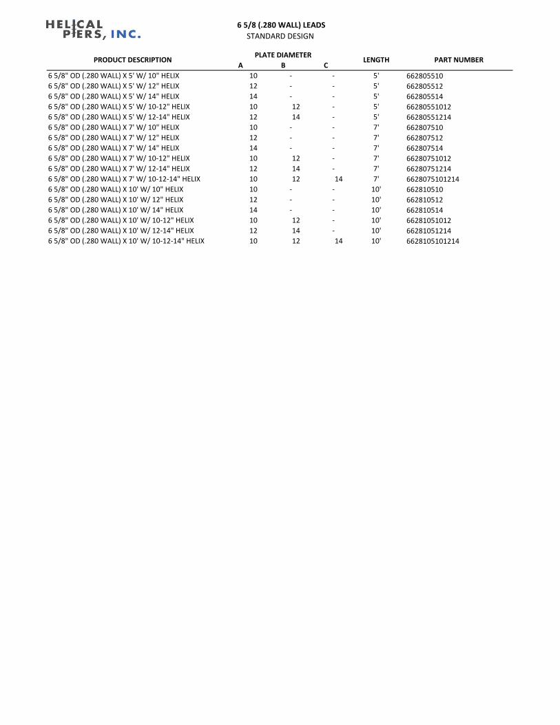
6 5/8 (.280 WALL) LEADS
STANDARD DESIGN
A B C
6 5/8" OD (.280 WALL) X 5' W/ 10" HELIX 10 - - 5' 662805510
6 5/8" OD (.280 WALL) X 5' W/ 12" HELIX 12 - - 5' 662805512
6 5/8" OD (.280 WALL) X 5' W/ 14" HELIX 14 - - 5' 662805514
6 5/8" OD (.280 WALL) X 5' W/ 10-12" HELIX 10 12 - 5' 66280551012
6 5/8" OD (.280 WALL) X 5' W/ 12-14" HELIX 12 14 - 5' 66280551214
6 5/8" OD (.280 WALL) X 7' W/ 10" HELIX 10 - - 7' 662807510
6 5/8" OD (.280 WALL) X 7' W/ 12" HELIX 12 - - 7' 662807512
6 5/8" OD (.280 WALL) X 7' W/ 14" HELIX 14 - - 7' 662807514
6 5/8" OD (.280 WALL) X 7' W/ 10-12" HELIX 10 12 - 7' 66280751012
6 5/8" OD (.280 WALL) X 7' W/ 12-14" HELIX 12 14 - 7' 66280751214
6 5/8" OD (.280 WALL) X 7' W/ 10-12-14" HELIX 10 12 14 7' 6628075101214
6 5/8" OD (.280 WALL) X 10' W/ 10" HELIX 10 - - 10' 662810510
6 5/8" OD (.280 WALL) X 10' W/ 12" HELIX 12 - - 10' 662810512
6 5/8" OD (.280 WALL) X 10' W/ 14" HELIX 14 - - 10' 662810514
6 5/8" OD (.280 WALL) X 10' W/ 10-12" HELIX 10 12 - 10' 66281051012
6 5/8" OD (.280 WALL) X 10' W/ 12-14" HELIX 12 14 - 10' 66281051214
6 5/8" OD (.280 WALL) X 10' W/ 10-12-14" HELIX 10 12 14 10' 6628105101214
PLATE DIAMETERLENGTH PART NUMBERPRODUCT DESCRIPTION

6 5/8 (.280 WALL) LEADS
HEX DESIGN
A B C
6 5/8" OD (.280 WALL) X 5' W/ 10" HELIX 10 - - 5' H662805510
6 5/8" OD (.280 WALL) X 5' W/ 12" HELIX 12 - - 5' H662805512
6 5/8" OD (.280 WALL) X 5' W/ 14" HELIX 14 - - 5' H662805514
6 5/8" OD (.280 WALL) X 5' W/ 10-12" HELIX 10 12 - 5' H66280551012
6 5/8" OD (.280 WALL) X 5' W/ 12-14" HELIX 12 14 - 5' H66280551214
6 5/8" OD (.280 WALL) X 7' W/ 10" HELIX 10 - - 7' H662807510
6 5/8" OD (.280 WALL) X 7' W/ 12" HELIX 12 - - 7' H662807512
6 5/8" OD (.280 WALL) X 7' W/ 14" HELIX 14 - - 7' H662807514
6 5/8" OD (.280 WALL) X 7' W/ 10-12" HELIX 10 12 - 7' H66280751012
6 5/8" OD (.280 WALL) X 7' W/ 12-14" HELIX 12 14 - 7' H66280751214
6 5/8" OD (.280 WALL) X 7' W/ 10-12-14" HELIX 10 12 14 7' H6628075101214
6 5/8" OD (.280 WALL) X 10' W/ 10" HELIX 10 - - 10' H662810510
6 5/8" OD (.280 WALL) X 10' W/ 12" HELIX 12 - - 10' H662810512
6 5/8" OD (.280 WALL) X 10' W/ 14" HELIX 14 - - 10' H662810514
6 5/8" OD (.280 WALL) X 10' W/ 10-12" HELIX 10 12 - 10' H66281051012
6 5/8" OD (.280 WALL) X 10' W/ 12-14" HELIX 12 14 - 10' H66281051214
6 5/8" OD (.280 WALL) X 10' W/ 10-12-14" HELIX 10 12 14 10' H6628105101214
PLATE DIAMETERLENGTH PART NUMBERPRODUCT DESCRIPTION

6 5/8 (.435 WALL) LEADS
STANDARD DESIGN
A B C
6 5/8" OD (.435 WALL) X 5' W/ 10" HELIX 10 - - 5' 664305510
6 5/8" OD (.435 WALL) X 5' W/ 12" HELIX 12 - - 5' 664305512
6 5/8" OD (.435 WALL) X 5' W/ 14" HELIX 14 - - 5' 664305514
6 5/8" OD (.435 WALL) X 5' W/ 10-12" HELIX 10 12 - 5' 66430551012
6 5/8" OD (.435 WALL) X 5' W/ 12-14" HELIX 12 14 - 5' 66430551214
6 5/8" OD (.435 WALL) X 7' W/ 10" HELIX 10 - - 7' 664307510
6 5/8" OD (.435 WALL) X 7' W/ 12" HELIX 12 - - 7' 664307512
6 5/8" OD (.435 WALL) X 7' W/ 14" HELIX 14 - - 7' 664307514
6 5/8" OD (.435 WALL) X 7' W/ 10-12" HELIX 10 12 - 7' 66430751012
6 5/8" OD (.435 WALL) X 7' W/ 12-14" HELIX 12 14 - 7' 66430751214
6 5/8" OD (.435 WALL) X 7' W/ 10-12-14" HELIX 10 12 14 7' 6643075101214
6 5/8" OD (.435 WALL) X 10' W/ 10" HELIX 10 - - 10' 664310510
6 5/8" OD (.435 WALL) X 10' W/ 12" HELIX 12 - - 10' 664310512
6 5/8" OD (.435 WALL) X 10' W/ 14" HELIX 14 - - 10' 664310514
6 5/8" OD (.435 WALL) X 10' W/ 10-12" HELIX 10 12 - 10' 66431051012
6 5/8" OD (.435 WALL) X 10' W/ 12-14" HELIX 12 14 - 10' 66431051214
6 5/8" OD (.435 WALL) X 10' W/ 10-12-14" HELIX 10 12 14 10' 6643105101214
PLATE DIAMETERLENGTH PART NUMBERPRODUCT DESCRIPTION

6 5/8 (.435 WALL) LEADS
HEX DESIGN
A B C
6 5/8" OD (.435 WALL) X 5' W/ 10" HELIX 10 - - 5' H664305510
6 5/8" OD (.435 WALL) X 5' W/ 12" HELIX 12 - - 5' H664305512
6 5/8" OD (.435 WALL) X 5' W/ 14" HELIX 14 - - 5' H664305514
6 5/8" OD (.435 WALL) X 5' W/ 10-12" HELIX 10 12 - 5' H66430551012
6 5/8" OD (.435 WALL) X 5' W/ 12-14" HELIX 12 14 - 5' H66430551214
6 5/8" OD (.435 WALL) X 7' W/ 10" HELIX 10 - - 7' H664307510
6 5/8" OD (.435 WALL) X 7' W/ 12" HELIX 12 - - 7' H664307512
6 5/8" OD (.435 WALL) X 7' W/ 14" HELIX 14 - - 7' H664307514
6 5/8" OD (.435 WALL) X 7' W/ 10-12" HELIX 10 12 - 7' H66430751012
6 5/8" OD (.435 WALL) X 7' W/ 12-14" HELIX 12 14 - 7' H66430751214
6 5/8" OD (.435 WALL) X 7' W/ 10-12-14" HELIX 10 12 14 7' H6643075101214
6 5/8" OD (.435 WALL) X 10' W/ 10" HELIX 10 - - 10' H664310510
6 5/8" OD (.435 WALL) X 10' W/ 12" HELIX 12 - - 10' H664310512
6 5/8" OD (.435 WALL) X 10' W/ 14" HELIX 14 - - 10' H664310514
6 5/8" OD (.435 WALL) X 10' W/ 10-12" HELIX 10 12 - 10' H66431051012
6 5/8" OD (.435 WALL) X 10' W/ 12-14" HELIX 12 14 - 10' H66431051214
6 5/8" OD (.435 WALL) X 10' W/ 10-12-14" HELIX 10 12 14 10' H6643105101214
PLATE DIAMETERLENGTH PART NUMBERPRODUCT DESCRIPTION

Hubbell Laboratories | Engineering Test Report May 30, 2018 | 1M18050-S1
This test report shall not be reproduced except in full, without written approval of the Laboratory. Page 1 of 10
Hubbell Power Systems, Inc • 210 North Allen Street • Centralia, Missouri 65240 Form EF-LAB-5.10-001, Rev A, 08/31/2016
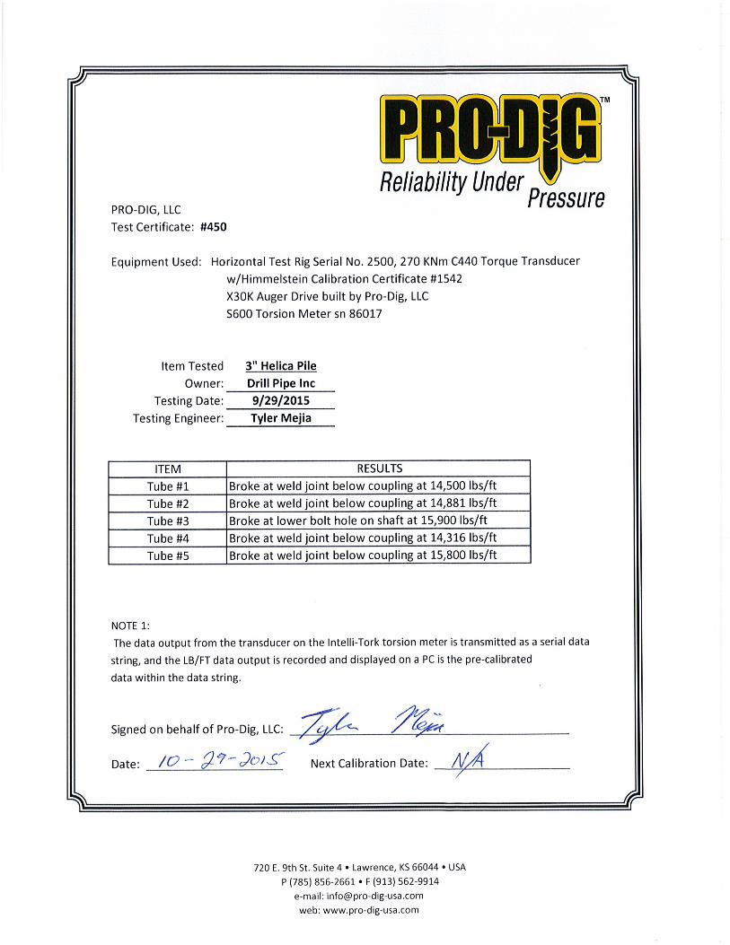
Test Report Number: 1M18050-S1
Test Request Number: M18-05-01
Test Report Date: May 30, 2018
Sample Description: (4) 2.875” HEX Pipe Extensions
Test Method Identification:
Torsion, Compression
Purpose of Test: Determine performance of a possible new round shaft coupling. Test samples provided by DPI (Drill Pipe, Inc.)
Tested for: Shawn Downey, Sr. Design Engineer Hubbell Power Systems, Inc., Civil Construction Business Unit 210 North Allen Street Centralia, Missouri 65240, USA
Test Performed By: Dustin Daum, Test Lab Technician
Report Written By: Ben Jennings, Application Engineer
Report Approved By: Gary Seider, Director of Engineering
Hubbell Laboratories | Engineering Test Report May 30, 2018 | 1M18050-S1
This test report shall not be reproduced except in full, without written approval of the Laboratory. Page 2 of 10
Hubbell Power Systems, Inc • 210 North Allen Street • Centralia, Missouri 65240 Form EF-LAB-5.10-001, Rev A, 08/31/2016
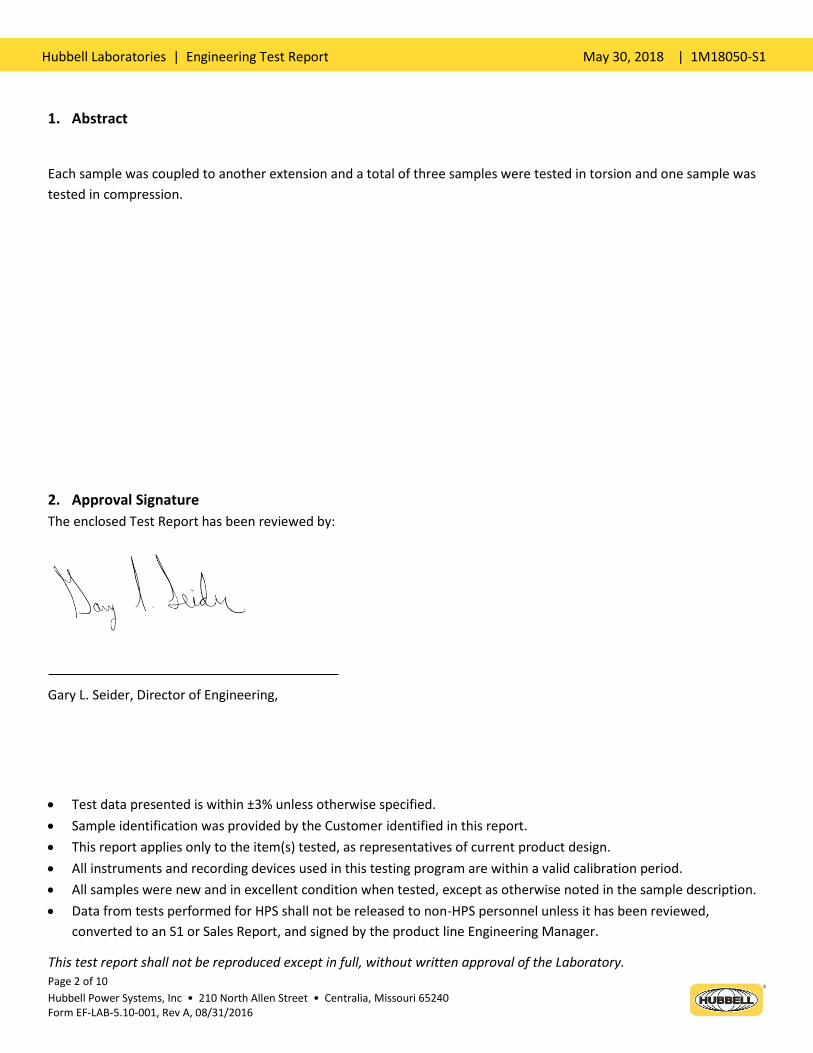
1. Abstract
Each sample was coupled to another extension and a total of three samples were tested in torsion and one sample was
tested in compression.
2. Approval Signature
The enclosed Test Report has been reviewed by:
Gary L. Seider, Director of Engineering,
Test data presented is within ±3% unless otherwise specified.
Sample identification was provided by the Customer identified in this report.
This report applies only to the item(s) tested, as representatives of current product design.
All instruments and recording devices used in this testing program are within a valid calibration period.
All samples were new and in excellent condition when tested, except as otherwise noted in the sample description.
Data from tests performed for HPS shall not be released to non-HPS personnel unless it has been reviewed,
converted to an S1 or Sales Report, and signed by the product line Engineering Manager.

Hubbell Laboratories | Engineering Test Report May 30, 2018 | 1M18050-S1
This test report shall not be reproduced except in full, without written approval of the Laboratory. Page 3 of 10
Hubbell Power Systems, Inc • 210 North Allen Street • Centralia, Missouri 65240 Form EF-LAB-5.10-001, Rev A, 08/31/2016

Hubbell Laboratories | Engineering Test Report May 30, 2018 | 1M18050-S1
This test report shall not be reproduced except in full, without written approval of the Laboratory. Page 4 of 10
Hubbell Power Systems, Inc • 210 North Allen Street • Centralia, Missouri 65240 Form EF-LAB-5.10-001, Rev A, 08/31/2016
3. Equipment List
Item Description Calibration Number
1
Riehle FS-160 Vertical Test Machine 6-3-067
2
Himmelstein Torque Readout/Torque Tester 6-3-011
4. Identification of Samples
Description of Samples: 2.875” HEX Pipe Extensions
Manufacturer: Hubbell Power Systems
Date of Receipt of Samples: May 4, 2018
Catalog Number: N/A
Special Comments: N/A
Applies to Samples Numbers: 4112-1-(1-3)
Tests Performed: Torsion
Description of Samples: 2.875” HEX Pipe Extensions
Manufacturer: Hubbell Power Systems
Date of Receipt of Samples: May 4, 2018
Catalog Number: N/A
Special Comments: N/A
Applies to Samples Numbers: 4112-1-4
Tests Performed: Compression
5. Test Procedures / Methods
Torsion:
A sample (two extensions coupled together) was placed in the Himmelstein Torque Tester. To facilitate the application
of a torsion load, a 1/2” thick hex washer was welded 2” from each end of the sample. The coupling section of each
sample was monitored for rotational deflection as load was applied. The load continually increased until an ultimate
value was achieved.
Compression:
A sample (two extensions coupled together) was shortened in length to facilitate applying a compression force. The
sample included the friction welded section as well as the female upset section. The sample was placed in the Riehle PS-

Hubbell Laboratories | Engineering Test Report May 30, 2018 | 1M18050-S1
This test report shall not be reproduced except in full, without written approval of the Laboratory. Page 5 of 10
Hubbell Power Systems, Inc • 210 North Allen Street • Centralia, Missouri 65240 Form EF-LAB-5.10-001, Rev A, 08/31/2016
160 Vertical Test Machine. A compression load was applied until an ultimate value or the machine’s capacity was
achieved.
6. Test Results
Torsion
Sample Machined Insert Hole Diameter (Inches)
Ultimate Torque (ft-lbs)
Coupling Deflection @ Ultimate
Comments
4112-1-1 1.0 18,676 < 1/4” Collapsed Upset, Assembly was still Easily Disassembled
4112-1-2 1.75 18,190 < 1/4” Broke Pipe @ Upset, Assembly was still Easily Disassembled
4112-1-3 1.75 18,130 < 1/4” Broke @ Friction Weld, Assembly was still Easily Disassembled

Hubbell Laboratories | Engineering Test Report May 30, 2018 | 1M18050-S1
This test report shall not be reproduced except in full, without written approval of the Laboratory. Page 6 of 10
Hubbell Power Systems, Inc • 210 North Allen Street • Centralia, Missouri 65240 Form EF-LAB-5.10-001, Rev A, 08/31/2016
Compression
Sample Machined Insert Hole Diameter (Inches)
Ultimate Load (lbs)
Comments
4112-1-4 1.0 159,520 No Damage or Deformation

Hubbell Laboratories | Engineering Test Report May 30, 2018 | 1M18050-S1
This test report shall not be reproduced except in full, without written approval of the Laboratory. Page 7 of 10
Hubbell Power Systems, Inc • 210 North Allen Street • Centralia, Missouri 65240 Form EF-LAB-5.10-001, Rev A, 08/31/2016
7. Photos
Typical Torsion Setup Device used to Monitor Rotational Deflection
Typical Rotational Deflection after Ultimate Load Sample 1 – Collapsed Upset

Hubbell Laboratories | Engineering Test Report May 30, 2018 | 1M18050-S1
This test report shall not be reproduced except in full, without written approval of the Laboratory. Page 8 of 10
Hubbell Power Systems, Inc • 210 North Allen Street • Centralia, Missouri 65240 Form EF-LAB-5.10-001, Rev A, 08/31/2016
Sample 2 – Broke in Upset Sample 3 – Broke in Friction Weld
Sample 3 – Broke in Friction Weld Sample 3 – Broke in Friction Weld

Hubbell Laboratories | Engineering Test Report May 30, 2018 | 1M18050-S1
This test report shall not be reproduced except in full, without written approval of the Laboratory. Page 9 of 10
Hubbell Power Systems, Inc • 210 North Allen Street • Centralia, Missouri 65240 Form EF-LAB-5.10-001, Rev A, 08/31/2016
Sample 3 – Broke in Friction Weld
Compression Setup After Compression Load

Hubbell Laboratories | Engineering Test Report May 30, 2018 | 1M18050-S1
This test report shall not be reproduced except in full, without written approval of the Laboratory. Page 10 of 10
Hubbell Power Systems, Inc • 210 North Allen Street • Centralia, Missouri 65240 Form EF-LAB-5.10-001, Rev A, 08/31/2016
After Compression Load After Compression Load
8. Conclusion
4 samples of 2.875” hex pipe extensions were prepared for testing. 3 were tested to failure in torque. The average
ultimate torque for these samples was 18,300ft-lbs (with the lowest being 18,130 ft-lbs). Of these three samples, two of
them failed on the upset side of the coupling and one broke the friction weld. The last sample was tested in
compression and had no damage or deflection at test machine’s maximum capacity (160 kips).