engine by sh a. k. mahajan
TRANSCRIPT

ENGINEENGINE
PRESENTATION BY A. K. MAHAJAN
Dy. General Manager (Excv), CWS, TADALI, WCL
What is an Engine?
An engine is a device which transforms the chemical energy of a fuel in to thermal energy and use this energy to produce mechanical work.
Heat Engines are classified into two broad types
a) External Combustion Engines
b) Internal Combustion Engines
External Combustion Engines
In an External Combustion Engine the product of combustion of air and fuel transfer heat to a second fluid which is the working fluid of the cycle
Example :-Steam Engine, Steam Turbine Plant

Internal Combustion Engines
In an Internal Combustion Engine the product of combustion are directly the motive fluid
Example :-Petrol, Gas, Diesel Engines, Jet engines & Rockets are also internal Combustion Engines
The above image is an early design for internal combustion four-stroke four-cylinder engine. The main idea for any engine is the existence of a combustion chamber, in which fuel-air mixture exists. Then, this mixture is allowed to burn; either using a spark or by increasing its temperature and pressure of the mixture. Due to combustion, energy is liberated and the piston is forced to move. Accordingly, it transforms the produced power to the gearbox using the crankshaft. It should also be noted that air is allowed to enter and mix with the fuel using the camshaft mechanism. As previously mentioned, the main difference between the engines are either the number of strokes or the cycle that is used to ignite the fuel.
An Internal Combustion Engine
The two most famous mechanism of actions are the two-stroke and four-stroke engines. As clear from its name, the only difference exists in the so-called stroke. This leads to different design considerations, and accordingly leads to distinguishable efficiency for each kind.

The stroke is defined as the length of the path that the piston goes through inside the cylinder. The upper end of the cylinder is referred to as the Top Dead Center (TDC), and the lower end is referred to as the Bottom Dead Center (BDC). Using the crankshaft mechanism, the linear motion that comes out from the piston due to the combustion is converted into rotational motion. Rotational motion is the required one to derive the wheels.
STROKE CATEGORIZATION
Two stroke engines are normally found in low power vehicles, such as: garden equipment, jet skis, and some motorcycles engines. From its name, the two-strokes engine refers to a type of an engine in which the process of combustion of a fuel and the liberation of mechanical energy takes place in only two strokes of the piston, the first goes from the top dead center to the bottom dead center, and vice versa for the second stroke. Starting from the point at which compressed fuel/air/oil mixture exists inside the piston, a spark is ignited from the spark plug, hence combustion. Combustion produces large energy that pushes the piston downward and exhaust gases are formed out of the combustion. Thus, the engine starts its first stroke in which it delivers power using the crankshaft and exhaust gases are liberated out of the cylinder from the exhaust valve.
TWO-STROKE ENGINES:
First stroke of the 2-stroke engine
As the piston proceeds downward, another valve is opened which is the fuel/air valve. Air/fuel/oil mixtures come from the carburetor, where it was mixed, to rest in an adjacent fuel chamber. When the piston moves downward more and the cylinder has no more gases, fuel mixture starts to flow to the combustion chamber and the second process of fuel compression starts. It is worth mentioning that the design carefully considers the point that fuel-air mixture should not mix with the exhaust. Therefore, the processes of fuel injection and exhausting should be synchronized to avoid that concern.

It should be noted that the piston has three functions in its operation:
1 - The piston acts as the combustion chamber with the cylinder, and it also compresses the air/fuel mixture and receives back the liberated energy and transfers it to the crankshaft. 2 - The piston motion creates a vacuum in order to such the fuel/air mixture from the carburetor, and pushes it from the crankcase (adjacent chamber) to the combustion chamber. 3 - The sides of the piston are acting like the valves, covering and uncovering the intake and exhaust ports drilled into the side of the cylinder wall.
Second stroke of the 2-stroke engine
ADVANTAGES AND DISADVANTAGES OF THE 2-STROKE ENGINE:
ADVANTAGES
1. It has no valves or camshaft mechanism, hence simplifying its mechanism and construction.
2. For one complete revolution of the crankshaft, the engine executes one cycle—the 4-stroke executes 1 cycle per 2 crankshafts revolutions.
3. Less weight and easier to manufacture.
4. High power to weight ratio
ADVANTAGES AND DISADVANTAGES OF THE 2-STROKE ENGINE:
DISADVANTAGES
1. The lack of lubrication system that protects the engine parts from wear. Accordingly, the 2-stroke engines have shorter life.
2. They do not consume fuel efficiently.
3. They produce lots of pollution.
4. Sometimes part of the fuel leaks to the exhaust with the exhaust gases.

In 1867, Nikolaus August Otto, a German engineer, developed the four stroke "Otto" cycle, which is widely used in transportation even today. Otto developed the four stroke internal combustion engine when he was 34 years old. Actually most of today’s gasoline cars use four stroke engines, which is a direct application for the thermodynamic cycle "Otto Cycle".
FOUR STROKE ENGINES: FOUR STROKE ENGINE
The cylinder of the four strokes engine differs from the two strokes engine. The major difference between both engines is the valves that are located on the top of the cylinder. These two valves open and close alternatively to allow either air/fuel mixture to enter or exhaust gases to come out. As it was previously mentioned, the motion of the two valves happen through the camshaft system. The spark plug is the one that ignites the compressed fuel-air mixture at a time when both valves are closed. Accordingly, the piston is pushed downward, transmitting power to the crankshaft. Power is then transferred to the wheel through other mechanisms.
The four strokes can be identified as follows
1. Suction Stroke.
2. Compression Stroke
3. Power Stroke
4. Exhaust Stroke.

First Stroke
Suction (Intake) stroke: During this stroke, the piston starts its motion from the top downward of the cylinder. Synchronously, the intake valve is opened (based on the camshaft mechanism), allowing air/vaporized fuel mixture to enter to the combustion chamber.
Suction (Intake) stroke:
Compression stroke: In this one, both valves should be closed. The piston starts to move upward to compress the fuel, until it reaches the top dead center. By compressing the fuel, the fuel temperature and pressure increases.
Second Stroke Compression stroke:

Third Stroke
Power Stroke: As the piston reaches the top dead center, the spark plug ignites a spark, allowing the fuel to burn. The combustion yields a high power that is transmitted through the crankshaft mechanism. It should be noted that in order for the combustion energy to be consumed efficiently in moving the piston, both valves should be closed.
Power Stroke:
Fourth Stroke
Exhaust Stroke: After reaching to the maximum displacement of the piston, most of the energy liberated is transferred. Accordingly, the pistons starts it back upward motion to get rid of the exhaust gases that result from combustion. At that moment, the exhaust valve is opened to allow it to go outside the cylinder.
Exhaust Stroke:

DIESEL CYCLE:
In the Diesel Cycle, named after Rudolf Christian Karl Diesel (1858-1913), only air is admitted in the intake stroke. The air is then adiabatically compressed, and fuel is injected into to the hot air in the form of many small drops (not a vapor). Each drop burns over a small time, giving an approximation of a isobaric explosion. The explosion pushes the cylinder outwards. The power stroke, valve exhaust, and exhaust stroke which follow are identical to those in the Otto Cycle
DIESEL CYCLE:
the only difference between is the Otto engine and diesel engine is that the latter does not require a spark plug to ignite the fuel; the fuel here is ignited under the effect of increase in pressure and temperature. In Diesel engines, compression ratios are as high as 22.5 to 1, where for Otto engines it normally does not reach even one fifth that number.
The four cycles of the diesel engine are:
1 - The piston is moved away from the cylinder head by the crankshaft, drawing only air into the cylinder. 2 - The piston moves towards the cylinder head, compressing the air. At the end of the stroke vaporized fuel is injected into the cylinder and is ignited by the high temperature of the air. 3 - The piston is forced away from the cylinder head by the gas, expanding after the ignition of the fuel. 4 - The exhaust valve is opened and the piston moves towards the cylinder head, driving the exhaust gases from the cylinder.

DIESEL CYCLE STROKE:
Diesel Engine Right Side View Family Similarities
•Oil Cooler •Fuel Pump Location
•Exhaust OutletLocation
•C. I. FlywheelHousing (8V/12V)
•Oil Filters •Auxiliary CoolerConnection
•EngineMounts
•Oil Fill & DipstickLocations
•DDC ECM•Air Inlet Location

Major Component Locations (Rear View)•Charge Air Cooler
•Turbocharger•Turbocharger
•Oil LevelGage
•Oil FillTube
•Accessory Drive •Accessory Drive
•Flywheel
•Oil Filters•Oil Pan
•Air CompressorDrive Location
•Flywheel Housing
Major Component Locations (Front View)
•Water Inlet
•Water Pump
•BeltTensioner
•Fan DrivePulley
•Oil FillTube
•FuelFilters
•WaterOutlet
•Charge AirCooler •Turbocharger
•ValveCover
•Alternator
•CrankshaftPulley•Front Cover
•Accessory Drive(SAE A)
•Accessory Drive(SAE C) (JWAC Only)
16 V Cylinder Block 16V Crankshaft

Connecting Rod Piston and Connecting Rod Assembly
Engine Coolant Pump
MAINTENANCE
means
MAINTAIN TO ENHANCE THE LIFE

You can always compare an Engine and its Systems with human body
Human Body
Respiratory SystemDigestiveBloodBody TemperatureExcretion System
Diesel Engine
Air SystemFuel System, Lubricating oil SystemCooling SystemExhaust System
Are you taking care of your engine similar to the care you take for yourself
Human Body Care Personal HygieneClean Food / WaterDaily Exercise
Periodic Health checks On time Medical HelpImmunization
Diesel Engine Care
Cleanliness / EnvironmentRecommended Fuel, Coolant & Lube OilScheduled Maintenance Checks Daily - 300 Hrs.,1500 Hrs.,6000HrsEngine health check up with Data loggerAnnual Maintenance ContractCorrect problem while they are simple
The Equipment Owner and Operator are responsible for safe operation in a hostile environment.
Maintenance is the key to lower the Operating cost. A Diesel engine requires regularly scheduled maintenance to keep it running safely.
Preventive Maintenance is the easiest and least expensive type of maintenance which permits the desired work at a convenient time.
WHY IS MAINTENANCE REQUIRED
•To operate
•To achieve operational reliability
•To achieve availability

• Sufficient fuel is available• Combustion air is dry and clean• Only trained personnel to be on job• Correct tools to be used• Only manufacturer recommended parts to be used• Fluids and lubrication as per manufacturer’s
recommendation
Maintenance related criteria
Correct care of your engine will result in Longer life, Better Performance and More economical Operation.
To get best service the operator must observe few rules and assume responsibility of engine care while engine is Operated as well as Maintained.
Guide lines of Equipment Manufacturer be followed :
Advantages :
• Prolonged useful life
• Prevent costly down time
• Optimum production
Disadvantages if not followed :
• Reduced life of engine & equipment
• Costly down time
• Production loss
Correct care of Engine / Equipment will result in
• Longer Life
• Better Performance
• More economical operation

Make sure all the gauges are operational
• Engine related gauges
• Equipment related gauges
Correct care of Engine
Engine related gauges and controls
• Engine oil pressure gauge
• Water Temperature gauge
• Engine oil temperature gauge
• Tachometer / Hour meter
• Dip stick - Oil level gauge
• Vacuum Indicator
• Fuel level indicator
• Air pressure gauge
Correct care of Engine
Engine related gauges and controls
Engine oil pressure safety control
Water temperature safety control
Fuel throttle control - accelerator
Correct care of Engine
Engine Starting Procedure : Carry out “A” check
• Check the gear lever for neutral position.
• Do not crank the engine for more than 10 seconds. Check the system if engine fails to start within 10 seconds.
• Start engine with throttle in closed position.
• Oil pressure must be indicated on the gauge within 15 seconds after starting. Continued operation will lead to serious engine damage.
• Run the engine at idle for 2-3 minutes and slowly accelerate the speed. This is to provide adequate lubrication to bearings.
Correct care of Engine

Engine Starting Procedure :
“A” check - ? The checks you need to carry out before
starting the engine every day.
• Check engine oil level - Conditions apply.
Equipment level, Quality & brand of oil, Dipstick handling and Time after stopping the engine.
Top up oil if required with SAE 15 W 40 grade and API CF4 specification
• Check engine coolant level - Conditions apply.
Check coolant level only when the system is cool ( <55 Deg C)
Top up if required with pre-mixed coolant. Do not use plain water
• Complain in case of any leakages / abnormalities
Correct care of Engine
Engine Starting Procedure :
“A” check - ?
• Check belts for damages, twisting, tightness etc
Check tension of new belts again after running 5 minutes for “Belt Tension after run-in”.
• Replace belts as sets only.
• Pulley misalignment not to exceed 1/16” for each ft.of DBPC.
• Belts should not bottom on grooves.
• Belts should protrude over 3/32” above top edge of groove.
• Belts should be dry.
Correct care of Engine
Engine Starting Procedure :
“A” check - ?
• Drain sediment from fuel tank / filters / water separator.
• Drain approximately 1 cup of fuel to remove water & sediments.
• Fill fuel as nearly full as possible since more condensation of water vapor occurs in partially filled tank.
• Ensure functioning of fuel gauge.
• Ensure fuel tank cap is tightened properly.
• Ensure exterior of the tank is free from mud / slush.
• Complain for leakage of fuel if any.
Correct care of Engine
Engine Starting Procedure :
“A” check - ?
• Check vacuum indicator for Red flag.
• Complain for appearance of red flag when ever noticed.
Correct care of Engine

Engine Shut-Down Procedure :• Idle the Engine for 3 to 5 minutes before shutting down, to allow lube oil & coolant to carry heat away from combustion chamber, bearings & shafts and Turbocharger.
• Release the key from the switch. Never leave the key on dash board.
Correct care of Engine
Engine Shut-Down Procedure : Safety
• Stop the engine immediately if sudden drop in oil pressure, unusual sound etc. with due care.
• This would save an engine from major damages if operator is alert and heed warning signs.
• Ensure all gauges and safety controls are in order.
Correct care of Engine
Don’ts : Do not idle the engine for excessively long period
• Excessive idling will cause the combustion chamber temperature to drop low.
• Fuel may not burn completely resulting in washing of lubricating oil off the cylinder walls and dilute the crank case.
• Clogging of injector spray holes, valves and piston rings to stick and improper lubrication due to oil dilution.
Correct care of Engine
Engine Speeds: Which is the best speed zone for an engine ?
Zone -I : Low Idle - Peak Torque
• Poor fuel economy
• Lead to over heating - reduced fan and coolant flow
• Low Turbo boost - Engine operates like a naturally aspirated engine.
• Loads like Torque converter and Hydraulic pumps will lug the engine speed down below peak torque RPM.
• Engine acceleration and recovery under load is unacceptable.
Not recommended to run at this speed zone.
Correct care of Engine

Engine Speeds: Which is the best speed zone for an engine ?
Zone - II : Peak Torque - Full load Governed Speed -
• Engine is most efficient in fuel consumption and power production
• Cooling system is most efficient
• Torsional levels are less
• All components operates the best.
ENGINE IS DESIGNED TO OPERATE IN THIS SPEED RANGE
Correct care of Engine
Engine Speeds: Which is the best speed zone for an engine ?
Zone - III : Full load Governed speed to No load High Idle -
• Limiting speed governor provided to protect engine from over speed
• Normally 10-12% greater than Governor cut off speed depending on parasitic load.
Extended High Idle operation is not recommended.
ENGINE RPM ABOVE HIGH IDLE RESULT SERIOUS DAMAGE AND CONSIDERED AS AN ENGINE ABUSE.
Correct care of Engine
Over Speed :
What are the causes of Engine over speed ?
• Improper gear shift
• Excessive vehicle speed during down hill
• Fuel pump tampering
Correct care of Engine
Over Speed : What are the common signs of engine over speed ?
• Bent or Broken push tubes or rod
• Valve stamping on pistons
• Worn valve collets
• Excessive valve lash
• Cross head shifting
• PT Pump “T” breakage
Correct care of Engine

Over Speed : What are the common signs of engine over speed ?
• Cam Gear Walk-off
• Tappet or cam roller pin failure
• Cam lobe damage
• Cross head shifting
• PT Pump “T” breakage
• Fly wheel and Damper mounting bolts loosened
Correct care of Engine
Common Complaints and action required:
Excessive Smoke Not taking load Abnormal Coolant and Oil Temperature Unusual Noise Excessive fuel, lube oil and coolant use Leakage of coolant, oil and fuel Engine hard starting Exhaust getting red hot
Recommended Engine Operating Parameters :
• Oil Temperature : 75 Degree C to 105 Degree C. Sudden increase in temperature is a cause of alarm.
• Coolant Temperature : 75 Degree C to 95 Degree C Ideal range is from 82 Degree to 88 Degree Celsius.
• Oil Pressure :
Non DFC system DFC system
At Idle speed : 1 to 2 Kg/cm 2. 0.7 Kg/cm2 Minimum
At rated speed : 3 to 7 Kg/cm 2 2.4 to 3.1 Kg/cm2
Oil pressure is established at normal temperature.
Maintenance Operations:
• Maintenance is the key to lower operating costs.
• A Diesel Engine requires regularly scheduled maintenance to keep it running efficiently.
Maintenance Schedule :
• A good Maintenance Schedule depends on engine application.
• The Schedule should be established using check sheet of O&M manual as a guide to meet a specific operation.
• Maintenance crew needs daily running reports from operators to initiate actions and

Maintenance Operations: “A” Maintenance Checks - Daily / Weekly
• Check engine oil level - Conditions apply.
Equipment level, Quality & brand of oil, Dipstick handling and Time after stopping the engine.
Grade : SAE 15 W 40
Specification : API CF4 / CH4
Oil Level
“A” Maintenance Checks - Daily / Weekly Check belts - Conditions apply
• Check tension of new belts again after running 5 minutes for “Belt Tension after run-in”.
• Replace belts as sets only.
• Pulley misalignment not to exceed 1/16” for each ft.of DBPC.
• Belts should not bottom on grooves.
• Belts should protrude over 3/32” above top edge of groove. Belts should be dry.
“A” Maintenance Checks - Daily / Weekly
• Check engine coolant level - Conditions apply.
• Check coolant level only when the system is cool ( <55 Deg C)
• Top up if required with pre-mixed coolant.
• Investigate for excess coolant loss / consumption.
• Arrest leakage if any
“A” Maintenance Checks - Daily / Weekly
• Drain sediment from fuel tank / filters / water separator.
• Drain approximately 1 cup of fuel to remove water & sediments.
• Fill fuel as nearly full as possible since more condensation of water vapor occurs in partially filled tank.
• Ensure functioning of fuel gauge.
• Ensure fuel tank cap is tightened properly.
• Ensure exterior of the tank is free from mud / slush.
• Arrest leakage of fuel if any.

“A” Maintenance Checks - Daily / Weekly
• Clean / Replace air cleaner element:
• Clean pre-cleaner and dust pan.
• Check vacuum indicator for Red flag.
• Clean or Replace Air cleaner elements : Conditions apply
• Cleaning can lead to rupture / microscopic damage to element. Hence, suggest to replace the element for longer life of engine.
• However, following suggestion can be followed for cleaning.
“A” Maintenance Checks - Daily / Weekly
Clean / Replace air cleaner element: Air cleaner Service Tips
1.Don’t remove the element for inspection.
2.Believe the indicator and if you don’t trust replace with new.
3.Never rap an element to clean it.
4.Never judge the filters life by looking at it. Measure restriction.
5.Never leave an air cleaner open longer than necessary.
6.Don’t ignore a worn or damaged gasket of cleaner
7.Don’t use a damaged or bunched element
8.Use clean and dry air with pressure not exceeding 60 PSI from in to out.
9.Inspect the element after cleaning for puncture.
10.Replace the outer element after 4-5 cleaning along with inner element.
“A” Maintenance Checks - Daily / Weekly
Clean / Replace air cleaner element: 7 steps Air filter Replacement.
1. Remove the element gently from the housing.
2. Wipe the inside of the housing with clean, damp cloth.
3. Ensure the hardened dirt ridges from gasket sealing surfaces are completely removed.
4. Check for uneven dirt pattern on element.
5. Press the rubber gasket on element and see that it springs back.
6. Make sure the gasket seats evenly in the housing.
7. Ensure air-tight-fit on all hoses, elbows and sealing components of air
“A” Maintenance Checks - Daily / weekly
• Clean / Replace air cleaner element : Two Common problems.
• Over Servicing.
• Improper Servicing.
Ensure,
• Exhaust system is leak proof.
• Fumes escaping from breather is not entering in to the air cleaner.• Check engine sound and parameters after starting the engine and before assigning for operation.

“B” Maintenance Checks - 300 hours or 6 months
Repeat “A” Maintenance Checks.
Lubricating System.
• Change lube oil, full flow & SLO by pass filter elements : Conditions apply.
• Cut open used element for metal particles.
• Use SAE 15W40 with CF4 classification.
• Install new filter with oil filled in it and torque the bolt to 35 ft.lbs.
• Recheck the oil level after 15 minutes of engine stopping and add oil up to “H” mark on dip stick.
“B” Maintenance Checks - 300 hours or 6 months
Cooling system.
• Check coolant for pH and Concentration and add ‘B’ check quantity if required.
• pH value of coolant : 8.5 to 10 ( Color of coolant if pink)
• Concentration level of coolant : 0.4 to 0.6 unit per liter.
• Concentration level should preferably at 0.4 unit per liter
“B” Maintenance Checks - 300 hours or 6 months
Fuel System
• Change fuel filter
• Clean fuel tank breather
• Check throttle linkage
Air System
• Check air piping
• Operation of vacuum indicator
• Record Oil Pressure
• Check for leakage-Correct if any.
“C” Maintenance Checks - First 1500 hours
• Engine breathing and fuel delivery to cylinders is vital for engine performance.
• Repeat “A” and “B” Maintenance Checks.
• Adjust injector and valves : conditions apply.
• Use only proper barring technique.
• Do not rotate the engine by pulling / prying fan.
• Use calibrated torque wrench / dial gauge for injector setting.
• Refer the table for correct set procedures (IBC / OBC / STC ).

Maintenance Operations: “C” Maintenance Checks - Every 1500 hours OR 1 year
• Engine breathing and fuel delivery to cylinders is vital for engine performance.
• Repeat “A” and “B” Maintenance Checks.
• Check fan hub, idler and water pump.
• Clean radiator externally
• Inspect starter & alternator
• Check evacuator valve
• Clean fuel tank from inside
• Check condition of coolant hoses / pipe coupling.
“C” Maintenance Checks - After every “D” check
• Perform all steps of ‘C’ check.
• Adjust Injector and valves.
“D” Maintenance Checks - Every 6000 hours OR 2 years
• Repeat “A” , “B” and ‘C” Maintenance Checks.
• Clean and calibrate Injectors
• Clean and calibrate fuel pump
• Clean cooling system by chemical cleaning / Pressure Flushing
• Inspect water pump, idler and fan hub for grease leakage and wobble.
• Check turbocharger bearing clearance.
• Inspect viscous vibration damper for fluid loss, dents, deformation and raising of dampers front cover plate.
“D” Maintenance Checks - Every 6000 hours OR 2 years
• Replace viscous vibration damper for the following problems.
1. Gear train failure
2. Accessory drive shaft failure
3. Crankshaft failure
4.Damper mounting cap screw failure
5.Flywheel mounting cap screw failure
6.Replace viscous damper at recommended intervals.
7.Inspect air compressor.
8. Tighten manifold cap screws

Maintenance Operations: Seasonal Checks
• Replace Hoses
• Particles of deteriorated hoses can be carried though oil and coolant and restrict the passages in particular radiator, coolant passages and oil cooler.
• Check thermostats and seals
• Tighten mounting bolt and nuts
• Check fan and drive pulley mounting
• Check crankshaft and drive assemblies end clearance.
• Steam clean the engine
Maintenance Operations: Troubleshooting
• Study the problem thoroughly. Ask questions.
• List out the probable causes and eliminate which are not the causes
• Do the easiest things first. Do not lose the evidences.
• Double check before beginning disassembly
• Find and correct basic cause of trouble
• Use right Tools and procedures to correct a complaint
• Carry out Test - for satisfactory performance
• Fail -safe - Educate the person who is responsible for the failure
• Use Troubleshooting Trees - for quick reference
Engine and its Systems
Engine is the prime mover of an equipment. Utmost care is hence required to keep the engine in Order so as to roll the equipment on the road.
• Air• Cooling• Fuel• Lube oil
Synchronized functioning of all these systems will lead to Synchronized functioning of all these systems will lead to Optimum output and lifeOptimum output and life
AIR SYSTEMComponents of Air System
• Air filter & housing• Air inlet piping• Turbocharger• CAC (Charged Air Cooler)• Intake manifold• Cylinder components

COOLING SYSTEMJacket Water Charge Cooling
To RadiatorThermostat
FromRadiator
WaterPump
ChargeAir
Cooler
Lube Oil Cooler
COOLING SYSTEMSeparate Circuit Charge Cooling
To RadiatorThermostat
FromRadiator
WaterPump
Lube Oil Cooler
ChargeAir
Cooler
AuxiliaryWaterPump
To AuxiliaryRadiator
FromAuxiliaryRadiator
FUEL SYSTEMFuel systems parts
• Fuel tank• Valve• Primary fuel filter• Water separator• Fuel pump• Secondary fuel filter• Fuel manifold• Fuel line kit• Nozzle assembly • Fuel cooler
Ten Maintenance Steps

10 Maintenance Steps
1. Keep Dirt out of the engine
2. Maintain a Lubricating oil film on bearing surfaces.
3. Regulate the Engine’s Fuel.
4. Control Operating Temperature.
5. Guard Against Corrosion.
6. Let the Engine Breathe.
7. Prevent Over speeding.
8. Know your Engine’s condition.
9. Correct Troubles while they are simple.
10. Schedule and control your maintenance.
Mining Construction
Compressor
Gas Compression
Rail
Oilfield PumpsFishing
Trawlers
Marine
Defense
EXCAVATOR’S ENGINE
• TATA EX1200 – QSK23C• BE1600 – QSX15 • BE1000 – BSA6D170• CAT RH90 – C18ACC (2 ENGINES 500 HP EACH)• PC650 – KT1150• EX350 – ISUZU• EX300 – 6CTA8.3/NT743• CK300 – NT855C/BC• BE300 - BS6D125/NT855FFC
DUMPER’S ENGINE
• CAT 793D 240T – CAT3516 HEUI• CAT 785C 120T – 3512 HEUI• CAT 777C/D 100 T – CAT3508 HEUI• BH100 – QST30• CAT 773D/E 50/60T – 3412 HEUI• BH60/50 – KTTA19C/QSK19• BH35-II – NTA855BC• LW35 – NTA855• R35 – NTA855• CAT1035N – 3406 DITA
DOZER/GRADER ENGINE
• D355 DOZER – BS6D170/KTA1150/QSX15• D155 DOZER – BS6D170/KT1150/QSX15• CAT D11R DOZER – CAT3508 HEUI• CAT 834B WHEEL DOZER – CAT3408 HEUI• CAT834G WHEEL DOZER– CAT3456 HEUI• CAT24M GRADER – CAT3412 HEUI• CAT14M GRADER – CAT C11 • BG825 GRADER – BS6D140

DRILL’S ENGINE
• RECP650 DRILL - NT855C/BC• IDM30 DRILL – NT855C/BC
DUMPER’S TRANSMISSION
• CAT 773B/D DUMPER – CAT50• BH60 DUMPER – M6610 A• 210M DUMPER - CLT6063• BH35-II – CLT754• R35 – CLBT754• LW35 – CLBT754• CAT1035N – CLT754
DOZER/GRADER TRANSMISSION
• D155 DOZER – D155• D355 DOZER – D355• CAT834B WHEEL DOZER- WD834B• BG825 GRADER – BG825


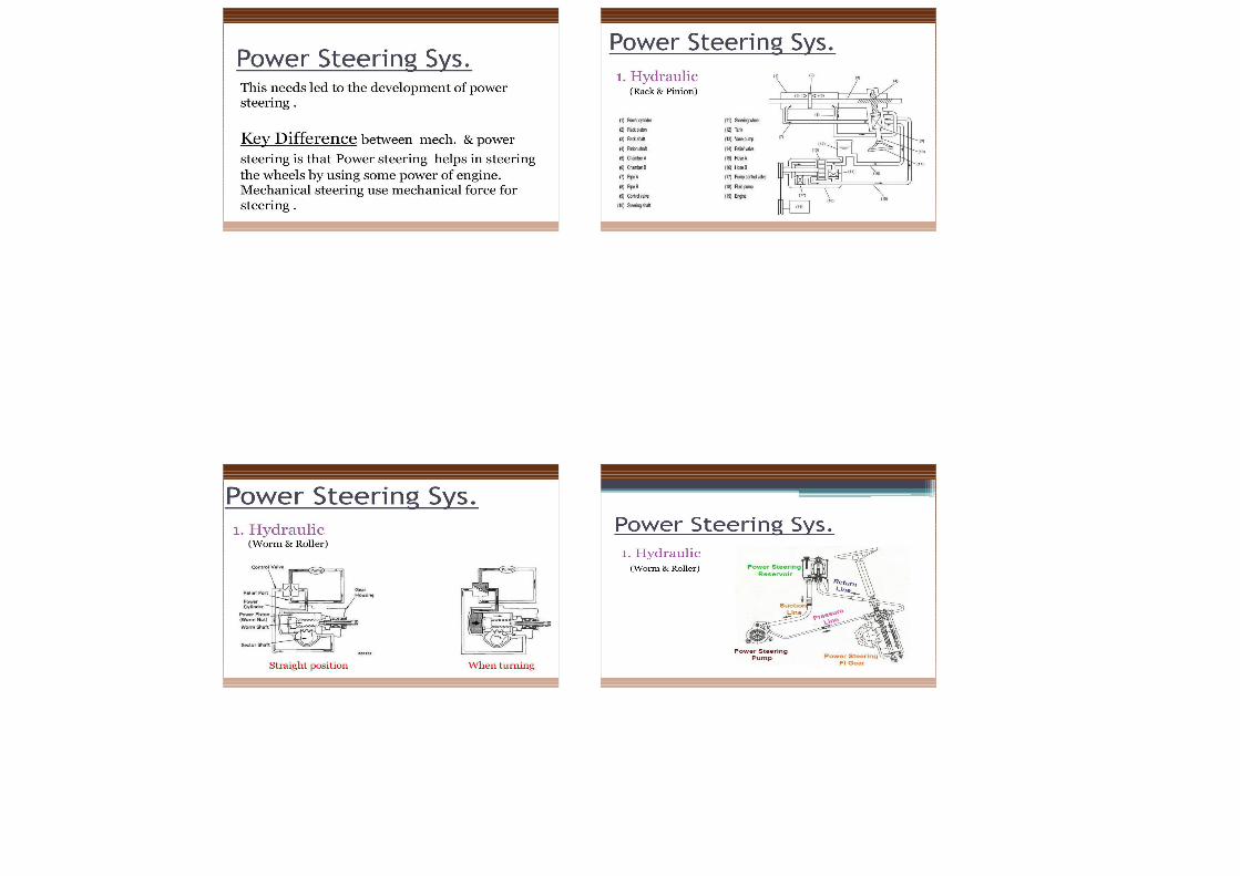
STEERING SYSTEM


CLUTCH, GEARBOX, DIFFERENTIAL & FINAL DRIVE
Transmission System
• Function of transmission:- It is used to transmit engine torque to the drivingwheels to drive the vehicle on the road.
4
Transmission System - Layout
6
ClutchFunction of clutch
• Clutch is used to disengage and engage theengine with rest of the transmission systems.
• To disengage while starting the engine andwhile changing gear ratio.
• To engage after starting of the engine and gearshift operation.
8

ClutchRequirement of Clutch• Transmit maximum torque of the engine.
• Engage gradually to avoid sudden jerks.
• Dissipate maximum amount of heat.
• Damp the vibrations and noise.
• Dynamically balanced.
• As small as possible.
• Easy to operate.9
Clutch Unit• Flywheel also acts as a driving
member
• Pressure plate is connected toclutch cover assembly.
• Clutch Cover assembly is bolted tothe flywheel.
• Clutch springs placed betweenPressure plate & Cover plate, pressthe Pressure plate against theclutch plate.
• Thus Clutch plate is squeezedbetween Flywheel & Pressure plate.
Classification of Clutch• Cone clutch
• Flat Plate clutch- Dry or Wet type clutch
- No. of friction plates(Single or Multiple)
- Actuation mode (Cable orHydraulic)
- Actuation spring (Helicalor Diaphragm)
• Centrifugal clutch11
Clutch Engaged & Disengaged• Clutch is always is in
engaged state.• It can be disengaged by
pressing of Clutch pedal.Disengagement is effected
by non - contact of Clutchplate both with Flywheelface & Pressure plate face.
• Frictional heat isdissipated by openingspresent in Clutch housing& Cover
12

Clutch Material
13
What is slipping of clutch?When there is lack of firm contact between the flywheel and pressure plate.
Reasons-- worn out lining, lack of free play, worn out splines on clutch shafts
What is ‘grabbing and chattering’ clutch?
A vehicles moves with a series of jerks or it vibrates and chatters during engagement.
Reasons- Too much play between gears, hardened lining, cracked or damaged pressureplate.
What is “dragging” clutch?
The driven plate does not stop rotating.
Reasons– Weak or broken pressure springs, not able to squeeze pressure plates

Gear Box• Gear box varies the leverage
(speed ratio & hence torqueratio) between the engine &driving wheels.
• It is located between Clutch &Propeller shaft.
• It is provided with either 4speed or 5 speed ratios or moredepending on design.
• Gear ratio is varied by Gearshift lever.
15
Need of Gear Box
14
Differential
A differential is a device, usually but not necessarily, employing gears capable of transmitting torque and rotation through three shafts, almost used in one of two ways-
1. Receives One input and provides two output. 2. Combines two inputs to create an output, that is the sum, difference, or average of the input.
Why Differential WasDeveloped?
Difficult and unpredictable handling, damage to tyres and road and strain on the entire drive train.

Purpose• To transfer the
engine power to thewheels
• To act as the finalgear reduction inthe vehicle
• To make the wheelsto rotate at different
speeds whilenegotiating a turn.
56
Differential: In Straight Ahead Motion Input torque is applied to
the ring gear, which turnsthe entirecarrier, providing torqueto both side gears, whichin turn may drive the leftand right wheels.
If the resistance at bothwheels is equal, thepinion gear does not
rotate, and both wheelsturn at the same rate.
57
Differential: In a Turn
• If the left side gear(red) encountersresistance, the piniongear(green) rotatesabout the left sidegear, in turn applyingextra rotation to theright side gear(yellow).
58
Axle Transmits rotary motion and torque from theengine-transmission-driveshaft to the wheels Changes torsional direction from longitudinal totransverse Provides speed reduction and torquemultiplication Provides a differential action to permit vehiclecornering Provides mounting points for suspension andbrakes
59

FINAL DRIVE ASSEMBLY
The final drive assembly employs a planetary gear unit to effect speed reduction and transmit power to the tyres, thus providing a large drive force.
Planetary Gear System
36
Planetary Gear System: Construction• Input shaft is connected to Ring gear(Blue)• Output shaft is connected to Plane carrier(Green) which is also
connected to Multi-disk clutch• Sun gear is connected to a Drum(Yellow), which can be locked
by brake band (Red). It is also connected to the other half ofClutch
37
Planetary Gear System: Operation• In Neutral
• Both band and clutch sets are released• Planets assembled to carrier with NRB• Ring gear only drive planet gear not the planet carrier
(Output shaft)• The planet gears drive the sun gears to spin freely
38

Planetary Gear System: Operation• In Low Gear (forward reduction)
• Band locks the sun gear by locking the drum• Planets walk around the sun gear• Planet carrier to spin in same direction as ring gear• Gear ratio= sun & ring teeth/no of teeth of ring gear
39
Planetary Gear System: Operation• In High Gear (Direct drive)• Band is released.• Lock any two members• Clutch is engaged so that the sun gear and planet
carrier is locked to act as a rigid member• Planets has to walk around the ring gear,• Ring Gear (Input shaft) will spin at the same speed as
the Planet Carrier (Output shaft)
40
Planetary Gear System: Operation• Reverse Gear
• Planet carrier is locked• Ring gear (Input shaft) will cause the sun gear(Output Shaft) to turn in the opposite direction
41
Compressors
Basic Classification and design overview

What are compressors?Compressors are mechanical devices that compresses gases. It is widely used in industries and has various applications
What are its applications?
Compressors have many everyday uses, such as in :
•Air conditioners, (car, home)
•Home and industrial refrigeration
•Hydraulic compressors for industrial machines
•Air compressors for industrial manufacturing
Refrigeration compressor

What are dynamic compressors?The dynamic compressor is continuous flow compressor is characterized by rotating impeller to add velocity and thus pressure to fluid.
It is widely used in chemical and petroleum refinery industry for specific services.
There are two types of dynamic compressorsCentrifugal CompressorAxial Flow Compressor
Centrifugal Compressor
Achieves compression by applying inertial forces to the gas by means of rotating impellers.
It is multiple stage ; each stage consists of an impeller as the rotating element and the stationary element, i.e. diffuser
Fluid flow enters the impeller axially and discharged radially
The gas next flows through a circular chamber (diffuser), where it loses velocity and increases pressure.
Axial flow compressorAxial flow compressorWorking fluid principally flows parallel to the axis of rotation. The energy level of air or gas flowing through it is increased by the action of the rotor blades which exert a torque on the fluid
Have the benefits of high efficiency and large mass flow rate
Require several rows of airfoils to achieve large pressure rises making them complex and expensive
Why multistage compressor?Why multistage compressor?
High temp rise leads into limitation for the maximum achievable pressure rise. Discharge temperature shall not exceed 150ºC and should not exceed 1350C for hydrogen rich servicesA multistage centrifugal compressor compresses air to the required pressure in multiple stages. Intercoolers are used in between each stage to removes heat and decrease the temperature of gas so that gas could be compressed to higher pressure without much rise in temperature
Intercooler

What are positive displacement compressors?
Positive displacement compressors causes movement by trapping a fixed amount of air then forcing (displacing) that trapped volume into the discharge pipe.
It can be further classified according to the mechanism used to move air.Rotary CompressorReciprocating compressor
Rotary compressorsThe gas is compressed by the rotating action of a roller inside a cylinder.
The roller rotates off-centre around a shaft so that part of the roller is always in contact with the cylinder.
Volume of the gas occupies is reduced and the refrigerant is compressed.
High efficient as sucking and compressing refrigerant occur simultaneously.
Reciprocating compressor
It is a positive-displacement compressor that
Uses pistons driven by a crankshaft to deliver gases at high pressure.
The intake gas enters the suction manifold, then flows into the compression cylinder
It gets compressed by a piston driven in a reciprocating motion via a crankshaft,
Discharged at higher pressure
How to select a particular type of compressor ?

Graph showing operating regions of various compressors
Taken from PIP REEC001 Compressor Selection Guidelines
Advantages and Disadvantages of dynamic compressors
Advantages Disadvantages
Dynamic Compressors
Centrifugal •Wide operating range•High reliability•Low Maintenance
•Instability at reduced flow•Sensitive to gas composition change
Axial •High Capacity for given size•High efficiency•Heavy duty•Low maintenance
•Low Compression ratios•Limited turndown
Advantages and disadvantages of positive displacement type compressor
Advantages DisadvantagesPositive displacement compressor
Reciprocating •Wide pressure ratios•High efficiency
•Heavy foundation required•Flow pulsation•High maintenance
Diaphragm •Very high pressure•Low flow•No moving seal
•Limited capacity range•Periodic replacement of diaphragm
Screw •Wide application•High efficiency•High pressure ratio
•Expensive•Unsuitable for corrosive or dirty gases
Selection Considerations Selection Considerations o Safety
a. Limiting gas properties (e.g., decomposition, flammability, toxicity). b. Compatibility of process gas with materials of construction c. Over-pressure protection

•Economics
a. Life-cycle cost b. User and vendor capabilities and facilities for maintaining equipment c. Expected equipment reliability
Block diagram of reciprocating compressor
It is a piston and cylinder device with (automatic) spring controlled inlet and exhaust valves
There is a clearance between the piston crown and the top of the cylinder.
Construction of Reciprocating Compressors
• Reciprocating compressors can be divided into two main groups.
1. Gas end.2. Power end.

Different Parts Of Gas End
Various parts of gas end are:• Cylinder & liner• Piston• Piston rod• Piston rod packing• Piston rings• Valves
Different Parts of Power End
Various parts of power end are• Crank and Crankshaft• Connecting rod• crosshead
Crank and crankshaft
crossheadConnecting rod
Shaft Power And Actual Power
Shaft power is the experimentally measured power required to run a compressor
It is given by
Actual power is defined as the power required for gas compression only . It is power integrated from an experimentally measured PV curve