“energy storage systems in the catenary grid of light rail...
TRANSCRIPT
Promoting Electric Public Transport
TROLLEY Project
Output 3.1.4 & Output 3.3.11
Transnational Manual on Advanced
Energy Storage Systems –
Part 0 – Introduction:
“Energy Storage Systems in
the Catenary Grid of Light Rail and
Trolleybus Systems”
as of September 2013
Prepared by: Barnim Bus Company mbH
(external expert: Fraunhofer IVI)
Status: Final Version
Dissemination level: Public Document
The TROLLEY project is implemented through the CENTRAL EUROPE
Programme co financed by the ERDF
TROLLEY Transnational Manual on Advanced Energy Storage Systems
TROLLEY Transnational Manual on Advanced Energy Storage Systems 2 of 26
This document has been prepared by the authors in the
framework of the TROLLEY project.
Energy Storage Systems in the Catenary Grid of Light Rail and Trolleybus Systems
Authors:
Dr.-Ing. Thoralf Knote
Dipl.-Ing. Beate Haufe
- Fraunhofer Institute for Transportation and Infrastructure Systems IVI -
Any liability for the content of this publication lies with the authors.
The European Commission is not responsible for any use that may be
made of the information contained herein.

TROLLEY Transnational Manual on Advanced Energy Storage Systems
TROLLEY Transnational Manual on Advanced Energy Storage Systems 3 of 26
Table of Contents
1. Introduction and Background
2. Storage Technologies - Overview
2.1 Battery Storage
2.1.1 High-Temperature Batteries
2.1.2 Lead-Acid Batteries
2.1.3 Nickel-Cadmium Batteries
2.1.4 Nickel-Metal-Hydride Batteries
2.1.5 Lithium-Ion Batteries
2.1.6 Redox-Flow Batteries
2.2 Flywheel Storage Systems
2.3 Electric Double Layer Capacitors
3. Summary

TROLLEY Transnational Manual on Advanced Energy Storage Systems
TROLLEY Transnational Manual on Advanced Energy Storage Systems 4 of 26
1. Introduction and Background
The INTERREG Central Europe project TROLLEY – Promoting electric public transport -
contributes to an improved accessibility of, and within, Central European cities, focusing on
urban transport. By taking an integrated approach the project has one main aim: the
promotion of trolleybuses as the cleanest and most economical transport mode for
sustainable cities and regions in Central Europe.
The Central Europe project TROLLEY (www.trolley-project.eu) is one consortium of 7
European cities: Salzburg in Austria, Gdynia in Poland, Leipzig and Eberswalde in Germany,
Brno in the Czech Republic, Szeged in Hungary and Parma in Italy. Horizontal support for
research and communication tasks is given by the University of Gdansk, Poland, and the
international action group to promote ebus systems with zero emission: trolley:motion.
The project TROLLEY promotes trolleybus systems as a ready-to-use, electric urban transport
solution for European cities, because trolleybuses are efficient, sustainable, safe, and –
taking into account external costs – much more competitive than diesel buses. The project
directly responds to the fact that congestion and climate change come hand in hand with
rising costs and that air and noise pollution are resulting in growing health costs. Trolleybus
systems are assisting with the on-going transition from our current reliance on diesel-
powered buses to highly efficient, green means of transportation. Therefore, the TROLLEY
project seeks to capitalise on existing trolleybus knowledge, which is truly rich in central
Europe, where trolleybus systems are more widespread.
The following document “Transnational Manual on Advanced Energy Storage Systems”
presents the results of feasibility and simulation studies as well as real-life evaluation reports
of TROLLEY’s pilot studies and pilot investment in the area of advanced energy storage
systems for trolleybus systems. The document exists of three parts: “Part 0” presents a
general introduction to different energy storage systems available in the market. “Part I”
describes on-board energy storage systems and shows the evaluation results of TROLLEY’s
investment pilots “installation of supercaps on trolleybuses” in Parma and the “installation
of a lithium-ion battery on a trolleybus” in Eberswalde. “Part II” illustrates the results of
TROLLEY’s feasibility studies for network based energy storage systems. It describes the
dimensioning of a network-based energy storage system on the basis of wayside installed
super capacitors in the networks of TROLLEY’s partner cities Eberswalde and Gdynia.

TROLLEY Transnational Manual on Advanced Energy Storage Systems
TROLLEY Transnational Manual on Advanced Energy Storage Systems 5 of 26
2. Storage Technologies - Overview
Depending on the method used to store the energy, mechanical, chemical, electrochemical,
electrostatic, thermal and thermochemical storage systems are differentiated. Table 1
displays typical samples for their application.
Storage system application areas differ for instance by capacity, duration and power. Figure
1 gives an overview of the power and discharge behaviour of different storage systems.
These storage systems range from single elements to large compound installations.
Table 1: Energy storing methods and application examples
Storing method Application
Mechanical - Pumped storage hydro power station
- Compressed air storage
- flywheel
Chemical - hydrogen, methane (by electrolysis and possibly following
methanation)
Electrochemical - battery (e.g. lead-acid, nickel-cadmium, nickelmetal-
hydride, lithium-ion, redox flow, sodium-sulfur, sodium-
nickel-chloride etc.)
Electrostatic - capacitor, double layer capacitor
- superconducting magnetic energy storage
Thermal - thermal energy storage (water, solid material)
thermochemical - latent heat storage units (phase transition between solid
and liquid state)
Energy storage systems can be used in public transport power grids for
- system voltage stabilization and
- intermediate buffering of recuperated energy to save traction energy.
For purpose of voltage stabilization, the storage level is held high at all times.

TROLLEY Transnational Manual on Advanced Energy Storage Systems
TROLLEY Transnational Manual on Advanced Energy Storage Systems 6 of 26
Figure 1: Classification of storage technologies by power and nominal discharge time;
adopted from Hannig (2009)
If the voltage level falls beneath a defined value, the storage feeds energy into the grid. In
energy-saving mode of operation, the storage level is held at a level that allows the
gathering of recovered energy in vehicles during braking as well as the supply of this energy
back into the power grid for traction purposes. These functions and the necessity of
installing stationary storage systems in places publicly accessible result in the following basic
requirements:
- high power supply and absorption,
- high charge-discharge efficiency,
- less energy losses,
- high system reliability,
- high number of charge-discharge cycles,
- compact construction with low size ratio,
TROLLEY Transnational Manual on Advanced Energy Storage Systems
TROLLEY Transnational Manual on Advanced Energy Storage Systems 7 of 26
- relatively low system costs and
- no improper risk to surrounding area and environment.
These requirements limit the diversity of storage media for the use in public transport power
grids. Pumped storage stations and compressed air plants are inappropriate due to their
dimension, stationary character and little number of charge-discharge cycles in the course of
a day. Chemical buffering as hydrogene or methane is coupled with high energy losses and
does not comply with the required response time. Thermal and thermochemical storages are
not suitable owing to the necessity of additional equipment for energy conversion. Super
conducting magnetic storages are restricted to niche applications in consequence of the
early state of research and development and very high costs.
As a result, only flywheel, double layer capacitor and accumulator systems are suitable for
stationary energy storing in the energy supply of public transport. These storage
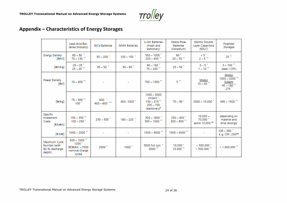
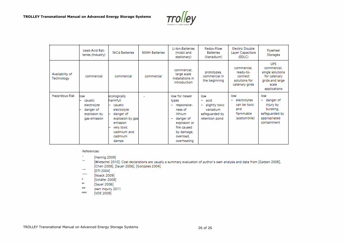
technologies and their applicability will be highlighted below. A survey on characteristics of
storage systems is given in the Appendix of this report. The survey intentionally includes
data from different sources to demonstrate data deviation and progress. Particularly novel
technologies are expected to cause significant power and energy increase and cost-cutting.
2.1 Battery Storage Systems
The term battery is commonly used for both primary and secondary batteries. Secondary
batteries are also called accumulators. Only these accumulators have the characteristic of
being rechargeable repeatedly and therefore they are qualified for electrical energy
buffering. Accumulators differ in used base materials, in structure and arrangement of
components, and in operating temperature. Batteries with low operating temperature are
used in most cases. These are for instance batteries based on of lead-acid (Pb), nickel-metal-
hydride (NiMH), nickel-cadmium (NiCd) and lithium in various material combinations. Among
these, lithium-ion (Li-Ion) batteries are expected to possess the highest potential for further
development. Sodium-sulfur (NaS) and sodium-nickelchloride (NaNiCl) batteries, so called
ZEBRA batteries, are known hightemperature batteries. Redox flow batteries differ from
others as they consist of an activity unit and spatially separated vessels for the reacting
agents. These battery types are depicted in more detail below.
2.1.1 High-Temperature Batteries

TROLLEY Transnational Manual on Advanced Energy Storage Systems
TROLLEY Transnational Manual on Advanced Energy Storage Systems 8 of 26
High-temperature batteries operate at a temperature of 270 to 350°C. Sodium-sulfur
batteries (NaS) use sodium and sulfur in a liquid state. As commercially available equipment
they can only be found in stationary use. Exclusive manufacturer is NKG Insulators Ldt. in
Japan and nearly all applications will be found there. References in literature differ regarding
the upkeep of the required process heat. [Wietschel 2010] specifies that no additional heat
input is necessary in case of good thermal insulation and daily charge and discharge. [Hannig
2009] points to additional heating during standby operation. This will lead to losses up to 14
until 18 percent per day. Calendrical durability is said to be approximately 6 to 15 years.
Favorable conditions enable a charge-discharge efficiency of about 70 to 80 percent. Power
and energy capacity of such NaS battery plants will reach the range of MW and MWh. For
example, Tsunashima Battery Plant of Tokyo Electric Power Company has a nominal energy
capacity of 48 MWh by 6 MW power. In public transport energy supply installations, NaS
batteries seem to be hardly acceptable due to the use of liquefied sodium and sulfur and
their environmental risks.
ZEBRA batteries operate at temperatures similar to NaS batteries, they also use liquid
sodium and are thermal isolated as well. Stand-by operation requires additional heating.
These heating losses add up to about 10 percent daily. The Swiss company FZ SONICK S.A.
(former MES-DEA) produces ZEBRA batteries at low lot level for use in electric vehicles
(Twingo-Elektra, IVECO Daily electric, 5 IVECO Irisbus Europolis in Lyon, 1 solar bus Tindo in
Adelaide). A second application area is energy supply for Rolls Royce submarine lifeboats. A
stationary 100 kWh pilot plant was installed in Canada. It is claimed that interconnections of
such installations would be possible, but none is known. Calendrical lifespan is specified with
8 to 10 years. For use as stationary storage equipment in energy supply of public transport
systems, they are less qualified due to their low charge-discharge cycles of approximately
1500 [Hannig 2009].
2.1.2 Lead-Acid Batteries
Lead-acid batteries are commonly well known. The respective technology is fully developed.
Batteries are commercially available from various producers and comparatively cheap.
Maintenance effort is relatively high and rises with battery life. Calendrical lifespan for
industrial purpose batteries is specified with 5 to 15 years. Despite the low number of
charge-discharge cycles, the use in public transport energy supply with frequent charging

TROLLEY Transnational Manual on Advanced Energy Storage Systems
TROLLEY Transnational Manual on Advanced Energy Storage Systems 9 of 26
and discharging required will reduce the lifespan of the battery considerably, if the whole
system is not oversized to avoid deep discharge. The application area of lead-acid batteries
involves automotive tasks as well as big installations. For instance, the former energy
supplier of Berlin (BEWAG) had used a lead-acid storage plant of 14 MWh and 17 MW [VDE
2009] for stabilization of frequency and voltage in the insulated grid of West Berlin. Supplier
Stadtwerke Herne owns a lead-acid installation of 1.2 MWh and 1.2 MW for buffering the
energy of a solar park nearby. With power and energy capacity obtainable from lead-acid
batteries, these installations seem to fit requirements of energy buffering and voltage
stabilization in catenary grids of trolleybuses and trams. However, the low number of
storage cycles poses an obstacle and no such application was found during the investigation.
2.1.3 Nickel-Cadmium Batteries
The technology of nickel-cadmium-batteries (NiCd) is sophisticated and has been well known
for about 100 years. Their commercial application area ranges from small applications in the
private sector over middle-sized industrial batteries to large storage plants in energy
distribution networks (Golden Valley Energy Authority’s system in Fairbanks is able to supply
power of 40 MW within 7 minutes, respectively 26 MW for 15 minutes [DTI 2004]). In
Europe they are offered primarily by the companies Hoppecke and Saft.
Because of the toxicity of cadmium, marketing and usage of NiCd batteries are severely
restricted in Europe today. In respect to European directives, German battery law [BattG]
permits batteries with more than 0.002 percent cadmium per weight to alarm and
emergency systems, cordless electric devices and old vehicles falling under Appendix II of
directive 2000/53/EC of the European Parliament and of the Council exclusively.
The ability to store and supply energy in the cold (temperatures of -20 to -40 °C) must be
considered an advantage of NiCd technology in comparison to other technologies.
Disadvantages are the relatively strong memory effect for recharging, the slightly lower
charge-discharge efficiency and the relatively high costs. Maintenance effort is said to be
lower than for lead-acid batteries [Price 2005]. The number of charge-discharge cycles is
almost the double of lead-acid batteries, but not enough for application in public transport
catenary grids.

TROLLEY Transnational Manual on Advanced Energy Storage Systems
TROLLEY Transnational Manual on Advanced Energy Storage Systems 10 of 26
Figure 2: NiCd-battery storage in Fairbanks, Alaska; Source: saft.com and [Price 2005]
2.1.4 Nickel-Metal-Hydride Batteries
The nickel-metal-hydride (NiMH) battery technology represents the follow-up of nickel-
cadmium technology by avoidance of cadmium. The scope of use ranges from consumer
area to powertrain applications with special focus to hybrid and electric vehicles. The
number of charge-discharge cycles, temperature stability and calendrical lifespan are less
than those of NiCd batteries. Large storage plants of NiMH batteries are unknown.
Therefore, usage of such batteries as stationary storage systems in catenary grids seems to
be quite unlikely.
2.1.5 Lithium-Ion Batteries
The term Li-ion battery includes various combinations of different electrolyte and electrode
materials. In the last decades, research and developement have caused continual
improvement of battery power and energy capacity as well as minimization of fire and burst
risk. (Lithium reacts vehemently with water and also air and nitrogen by exothermal
reaction.) Unlike other battery types, Li-ion batteries feature very high energy and power
densities, a high charge-discharge efficiency and a better cycle stability. However, a battery
management system with single cell control and charge equalization is necessary to operate
them and to keep the operating voltage level for each cell.
Li-ion batteries are known mainly from portable applications in consumer electronics. These
batteries are in the power and energy range of some W or Wh respectively. Currently, Li-ion
batteries in kW and kWh range gain increasing importance in the field of powertrain supply
of electric and hybrid vehicles. First stationary storage facilities (75 units with 5 to 15 kWh
each) are tested in-situ in Germany and France within the research project SolIon [Saft
TROLLEY Transnational Manual on Advanced Energy Storage Systems
TROLLEY Transnational Manual on Advanced Energy Storage Systems 11 of 26
2009]. These Li-ion batteries by company Saft are said to be completely maintenance-free.
They serve as buffer for energy from net coupled photovoltaic installations with maximum
power of 5 kWsolar. Furthermore, Li-ion batteries from Saft are used as domicile store of
photovoltaic energy in Guadeloupe, Réunion.
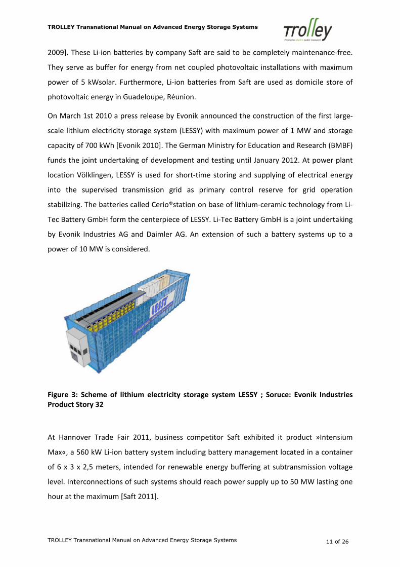
On March 1st 2010 a press release by Evonik announced the construction of the first large-
scale lithium electricity storage system (LESSY) with maximum power of 1 MW and storage
capacity of 700 kWh [Evonik 2010]. The German Ministry for Education and Research (BMBF)
funds the joint undertaking of development and testing until January 2012. At power plant
location Völklingen, LESSY is used for short-time storing and supplying of electrical energy
into the supervised transmission grid as primary control reserve for grid operation
stabilizing. The batteries called Cerio®station on base of lithium-ceramic technology from Li-
Tec Battery GmbH form the centerpiece of LESSY. Li-Tec Battery GmbH is a joint undertaking
by Evonik Industries AG and Daimler AG. An extension of such a battery systems up to a
power of 10 MW is considered.
Figure 3: Scheme of lithium electricity storage system LESSY ; Soruce: Evonik Industries
Product Story 32
At Hannover Trade Fair 2011, business competitor Saft exhibited it product »Intensium
Max«, a 560 kW Li-ion battery system including battery management located in a container
of 6 x 3 x 2,5 meters, intended for renewable energy buffering at subtransmission voltage
level. Interconnections of such systems should reach power supply up to 50 MW lasting one
hour at the maximum [Saft 2011].

TROLLEY Transnational Manual on Advanced Energy Storage Systems
TROLLEY Transnational Manual on Advanced Energy Storage Systems 12 of 26
Due to the novelty of Li-ion technology, energy density and high charge/discharge efficiency
of 90 to 95 %, a great development potential is expected furthermore. Increasing
commercial usage of such batteries is expected to cause significant cost reduction. The
abovementioned trend for development of large-scale Li-ion battery systems will possibly
make them an interesting option for stationary energy buffering in the catenary grid of
trams and trolleybuses.
2.1.6 Redox-Flow Batteries
Redox-flow batteries consist of two liquid electrolytes containing soluble salts as active
matter. The electrolytes are stored in separate external tanks. For electricity production
these liquids are pumped through the central electrochemical reactor unit and afterwards
back into the tanks. Thanks to the external storing of the electrolytes the energy capacity of
redox-flow batteries can be increased by expanding the tanks and the amount of electrolyte.
The number of reaction cells building the electro-chemical reactor unit defines the power
output. Self-discharge of redox-flow batteries is very low, as this process can only appear
within the electro-chemical reactor unit. Long-term energy storage is therefore provided.
Figure 4: Schematic diagram of a redox-flow battery on base of vanadium electrolytes
By applying the redox-flow principle, a large diversity of material combinations is potentially
usable. Systems with both electrolytes on base of vanadium seem to be the fittest for the

TROLLEY Transnational Manual on Advanced Energy Storage Systems
TROLLEY Transnational Manual on Advanced Energy Storage Systems 13 of 26
future, because the electrolytes cannot be poisoned by interfusingn. With all ancillary units
taken into account, this battery type reaches a charge-discharge efficiency of about 75 %.
Energy density is comparable to lead-acid batteries. In contrast to other battery systems,
charge/discharge cycle stability is high. Acid electrolytes and the relatively weak toxic
vanadium can generate hazards.
Storage plants up to the range of MW and MWh have already been built. For instance,
American Prudent Energy Corporation installed a few plants for use with wind farms in
Japan. These installations are built from 7 kW units, possess a nominal power of 4 MW and a
nominal energy of 6 MWh.1 1 However, it is worth to mention that a row of planned
installations of other manufacturers were not implemented or only as a prototype. In
Germany some institutes of the Fraunhofer-Gesellschaft are developing vanadium-redox-
flow batteries. Currently, they are testing prototypes with 1 to 2 kW power. A system in MW
range is planned for 2016.
To sum up, it can be said that even though commercial applications are already available,
redox-flow battery technology is still in a prototypic status. Therefore, their use as stationary
energy buffer in catenary grids has to remain an objective for the future. Additionally, it
must be kept in mind that redox-flow batteries require a relatively large volume.
2.2 Flywheel Storage Systems
Flywheels use the kinetic energy of a rotating mass for energy storing. In the beginning they
were made from steel and their rotation velocity was low (3000 to 5000 rounds per minute).
Today’s innovative systems consist of high-tensile carbon fiber composites (CFK) and operate
at 20,000 up to 60,000 rounds per minute. The amount of energy stored in a flywheel is
proportional to inertia of the rotating mass and to the square of its rotational speed.
Therefore, higher energy density and more compact constructions are achieved by fast
running systems. Energy conversion takes place via a motor-generator system that speeds
the flywheel mass up for energy storing and converts the rotational energy into electrical
energy during discharging. Despite of sophisticated bearing and vacuum operation, energy
losses are very high. Therefore, flywheels are qualified for short time buffering only. Their
1 Prudent Energy Corporation, Fallstudie Japan, www.pdenergy.com/pdfs/casestudy_japan.pdf,
Accessed 15. 4. 2011
TROLLEY Transnational Manual on Advanced Energy Storage Systems
TROLLEY Transnational Manual on Advanced Energy Storage Systems 14 of 26
main advantages consist in an extremely quick reaction for charge or discharge request
including high power requests, a high charge-discharge efficiency of 90 to 95 %, a high cyclic
lifespan of about 1 million cycles, a high calendrical lifespan and high system reliability.
Additionally, only low maintenance effort is necessary. These properties make them
interesting for voltage stabilization and buffering of recuperated energy in catenary grids. A
second application area is the delivery of momentary backup power in uninterruptable
power supply (UPS) systems.
Further applications are found in maritime and military sectors and in nuclear engineering.
As prototypes, flywheels had been used to buffer energy gathered during breaking at the
vehicle itself for later usage. In electric transmission grids, flywheels are operated as a fast
control energy reserve. In the first halfyear of 2011, a flywheel storage plant of 20 MW
power is intended for connection to the net in Stephentown, NY. This plant is built by 200
carbonfiber flywheels of Beacon Power, each with 16,000 rounds per minute, 100 kW power
and 25 kWh energy content. Thereby, 1 MW unit consists of 10 storages each plus one
transformer.
Flywheel systems entail a relatively low hazardous risk because scarcely any toxic material is
used in them. The only risk exists in bursting due to the strong rotatory forces. This danger
can be obviated by an appropriate containing of the system.
Flywheels have been commercially obtainable for quite some time. Especially the more
slowly turning systems are technically mature. Perfection of fast turning systems is a
continuing subject of research. There is a number of companies producing flywheel storage
systems, among them German companies like Piller Power Systems in Osterode/Harz and
Rosseta Technik GmbH in Roßlau. Further producers in non-exhaustive enumeration are
CCM Centre for Concepts in Mechatronics B.V. in the Netherlands, Hitec Power Protection,
Urenco Power Technologies, Active Power, Beacon Power, Kinetic Traction Systems, Inc. or
SatCon Power Systems.
In contrast to the abovementioned energy storage technologies, flywheel storages have
been used several times as stationary energy buffers in public transport catenary grids.
Detailed information about these applications can be found in publications, some of which
are mentioned below.

TROLLEY Transnational Manual on Advanced Energy Storage Systems
TROLLEY Transnational Manual on Advanced Energy Storage Systems 15 of 26
Already in 2000, a Powerbridge flywheel system from Piller Power Systems was installed at
üstra Transport Company in Hannover [Briest 2000]. This flywheel was a commercial one,
manufactured for use as uninterruptable power supply. The flywheel mass was made from
steel and turned with 3600 rounds per minute. Its maximum power was 1 MW and the
usable energy content amounts to approximately 5 kWh. Until the end of 2003, four of these
systems have been installed. In analysis of long lasting data collection, energy savings of
450,000 kWh per annum were demonstrated [Kähler 2005]. Such systems have also been
used in the metro grid of Hamburger Hochbahn. The first one was installed in 2007 and the
second in 2010. Decisive reasons for using a flywheel have been short reaction time and
relatively low costs. In [Steinhorst 2008], savings of more than 430,000 kWh per annum
were forecast after the first operation experience. For economic optimization, the storage is
switched off at operation shutdown from midnight to the early morning. Further flywheels
of the same producer are situated in the catenary grid of the public transport operators
RATP in Paris, BKV in Budapest and HTM in Den Haag.
The first storage test of a flywheel from Rosetta Technik GmbH was carried out at the energy
supply system of the public transport operator in Dessau. Another flywheel was taken into
operation in the Zwickau tram grid in 2007. This flywheel turns with up to 25,000 rounds per
minute, provides up to 1 MW power und possesses a usable energy content of 4 kWh. In
[Täubner 2007], detailed information about technical data and maintenance effort is
reported. As annually maintenance tasks, oil change of the vacuum pump and the bearing,
chiller cleaning and a diagnostic inspection are mentioned by Rosetta Technik GmbH for
checking the overall status of the system. In contrast to information given by [Hannig 2009],
a 20 years calendrical lifespan is expected not only for the flywheel but also for the bearing.
Besides the storage type used in Zwickau, Rosetta offers flywheels made from steel and
small format carbon fiber flywheels. These storages shall be traded in the future via KAMAG
Transporttechnik GmbH & Co. KG in Ulm.

TROLLEY Transnational Manual on Advanced Energy Storage Systems
TROLLEY Transnational Manual on Advanced Energy Storage Systems 16 of 26
Figure 5: Energy storage unit of the Zwickau tram grid with flywheel of Rosetta Technik
GmbH; Source: Rosetta
In addition, Zurich public transport operator tested a flywheel storage device at a steep
route section of its tram net in late summer 2009. Taking into consideration frequent
services at this section with braking energy reuse efficiency of 85 %, the supplemental
energy saving potential was too low and uneconomical.
Kinetic Traction Systems, emanated from Pentadyne Corporation and Urenco, offers fast
turning carbon fiber flywheels especially for public transport systems. These storages were
tested at rail and metro systems in New York, London and Lyon. By own account of Kinetic
Traction Systems, these storages will reach up to 10 million charge-discharge cycles and a
calendrical lifespan of 20 years at least.
In summary it must be said that stationary flywheel storages offer a row of applications in
public transport energy supply. For optimal operation, an adaption to local conditions is
always necessary.
2.3 Electric Double Layer Capacitors
Electric double layer capacitors (EDLC) are also known as super, gold or ultracaps. By means
of the electric double layer, they can store considerably more energy than conventional
capacitors. Nevertheless, their energy density is very low in comparison with other electric
storages. Assets of these storages are fast charging and discharging of high power, at least
500,000 recharging cycles, a charge-discharge efficiency of about 95 % and a calendrical
lifespan of approximately 10 years. Electric storage losses are lower than those of flywheels

TROLLEY Transnational Manual on Advanced Energy Storage Systems
TROLLEY Transnational Manual on Advanced Energy Storage Systems 17 of 26
but higher than those of accumulators. Thus they are predetermined as short time storage
medium with high power output. The only disadvantage consists in relatively high costs.
The hazard potential of EDLC is low. Solely the use of acetonitrile as electrolyte in some
types of EDLC bears a risk of fire and poisoning. In Japan, the use of acetonitrile as
electrolyte is interdicted. In Europe this electrolyte has not been banned yet but researchers
look for materials to replace it. Electric double layer capacitors are evaluated as special
refuse. Hence EDLCreplacement produces disposal causes additional costs. Therefore,
conditions of return should be fixed already during purchase negotiations.
The EDLC application area ranges from automotive to the coverage of supply quality in
power grids. Companies like Maxwell Technologies, Panasonic, NESS Capacitor Company,
WIMA and others produce and offer EDLC. For use as stationary storage systems in catenary
grids, ready-to-connect systems are offered by rail systems manufacturers Siemens and
Bombardier. For research purposes, such an installation was developed at Fraunhofer
Institute for Transportation and Infrastructure Systems IVI.
Figure 6: Fraunhofer IVI Stationary EDLC Storage System
The name of the Siemens system is Sitras SES - energy storage system for mass transit
systems. It is designed for DC traction power supply systems at 600 and 750 V. Useable
energy content is 2.5 kWh and maximum power is 700 kW. One system consists of four
double cubicles (dimensions: 2 cubicles per 1.4 x 0.7 x 2.6 m and 2 cubicles per 1.3 x 2.0 x 2.6
TROLLEY Transnational Manual on Advanced Energy Storage Systems
TROLLEY Transnational Manual on Advanced Energy Storage Systems 18 of 26
m). For installation alongside the track, the system is also available as a ready-mounted
container version. Cascading of energy content is possible. The system is able to switch
automatically between the operation modes energy saving and voltage stabilization.
Maintenance effort is specified as lower than that of flywheel systems. Siemens specifies
possible energy savings as up to 500,000 kWh per year. The first prototype of such stationary
energy storage equipment worldwide was installed at Cologne Transit Authorities light rail
route 1 in March 2001. Furthermore, installations took place in Portland, Dresden, Madrid,
Bochum und Peking. By now four such systems work in Cologne and two in Madrid.
Bombardier’s storage system is named EnerGstor™ and is one part of Bombardier’s
environmental technology brand ECO4™. The system is scalable and its energy content can
be dimensioned from 0.25 up to 5.0 kWh or more. It is designed for the use in DC traction
power supply systems at 600 and 750 V. Optionally a variant for use with 1500 V/DC is
obtainable. As a means of finding the most economic option for operation, the simulation
tool EnerGPlan™ by Bombardier can be used. Compact construction, no necessity of public
work for use in standard situations and low hardware and installation costs were mentioned
as the essential features of the system. The maximum power of storage systems with a
useable energy content of 1 kWh is numbered to 650 kW. Its dimensions are 1.8 x 1.8 x 2 m.
During the projected lifespan of such an EnerGstor system, no running maintenance is
required besides simple basic tasks like inspections and preventive cleaning.
3. Summary
Nearly all described energy storage system types can be installed on-board to store energy,
either by way of a battery, which can provide much energy for quite a long time, but has a
long charging time, or by way of ultracaps or supercaps, which can be charged extremely
fast, but have to supply the stored energy as fast as possible. Therefore, it is important by
the dimensioning of trolleybus networks to harmonise the energy storage unit (size, weight,
capacity) to the basic technology and the intended operating schedule.
Due to their relatively low number of charge-recharge cycles, battery storage systems are
usually not suitable as stationary energy storages in catenary grids. Opportunities for future
use might potentially open up from the latest developments of large-scale Li-ion battery
systems.
TROLLEY Transnational Manual on Advanced Energy Storage Systems
TROLLEY Transnational Manual on Advanced Energy Storage Systems 19 of 26
Flywheel storage systems are successfully applied as stationary energy storages by some
public transport operators. Only the storage systems themselves are offered commercially.
Additional necessary installation work and, where required, building measures for
connection to the catenary grid have to be carried out in cooperation with the
manufacturer.
On the base of electric double layer capacitors, ready-to-connect storage systems are
offered by two large railway systems providers. Operation experience can be found at
several public transport operators since 2001. The offered EDCL-storage systems are scalable
and equipped for fast installation with less installation and maintenance effort.
TROLLEY Transnational Manual on Advanced Energy Storage Systems
TROLLEY Transnational Manual on Advanced Energy Storage Systems 20 of 26
4. References
Frequently Used Internet Sources
Beacon Beacon Power www.beaconpower.com
Evonik Evonik Industries AG corporate.evonik.com, www.evonik-steag.de
GAIA GAIA Akkumulatorenwerke GmbH www.gaia-akku.com
Hitec Hitec Power Protection www.hitec-ups.com
HOPPECKE HOPPECKE Advanced Battery Technology GmbH www.hoppecke.com
KTS Kinetic Traction Systems, Inc. www.kinetictraction.com
Li-Tec Li-Tec Battery GmbH www.li-tec.de
FZ SONICK FZ SONICK S.A. (Ehemals MES DEA Divisione Energie Alternative)
www.fzsonick.com,
www.cebi.com/cebi/content/index_html?a=5&b=9&c=19&d=69
Piller Piller Power Systems GmbH www.piller.com
Produktinformation - UNIBLOCK UBT – Rotierende USV von 400kVA-
50MVA
Prudent Prudent Energy Corporation, USA, www.pdenergy.com
Rosetta Rosetta Technik GmbH www.rosetta.de
Saft Batterien Saft Industrial Battery Group www.saftbatteries.com
TROLLEY Transnational Manual on Advanced Energy Storage Systems
TROLLEY Transnational Manual on Advanced Energy Storage Systems 21 of 26
Literature
BattG |Gesetz über das Inverkehrbringen, die Rücknahme und die umweltverträgliche
Entsorgung von Batterien und Akkumulatoren (Batteriegesetz - BattG), www.gesetze-im-
internet.de/bundesrecht/battg/gesamt.pdf, Zugriff v.17.12.2012
Beacon 2010 | Beacon Power: 20 MW Frequency Regulation Plant, November 3, 2010,
www.beaconpower.com/files/DOE-ESS-update-ppt-11.10.pdf, Zugriff v. 17. 3. 2011
Briest 2000 | Briest, R., Kähler, S.: Einsatz routierender Energiespeicher im Fahrleitungsnetz
der üstra Hannover. In eb - Elektrische Bahnen (98), 2000, Heft 5/6, S. 214 – 221
Bombardier EnerGstor | Bombardier Transportsysteme, Produktinformation: EnerGstor –
Streckenseitige Energiespeicherung, www.bombardier.com/files/de/supporting_docs/BT-
ECO4-EnerGstor.pdf, Zugriff vom 15.3.2011
Chen 2008 | Chen, H. u. a.: Progress in electrical energy storage system: A critical review. In:
progress in Natural Sience 19 (2009) S. 291-312
DTI 2004 | DTI - GLOBAL WATCH MISSION REPORT: Electrochemical Energy Storage – a
Mission to the USA, November 2004,
www.spinnovation.com/sn/Batteries/GLOBAL_WATCH_MISSION_REPORT.pdf, Zugriff v.
18.4.2011
Evonik 2010 | Evonik Industries, Pressemitteilung vom 1. März 2010: Evonik entwickelt die
größte Lithium-Keramik-Batterie der Welt,
www.evoniksteag.de/sites/energy/de/presse/Pages/news-details.aspx?newsid=10311,
Zugriff v. 26.4.2011
Gatzen 2008 | Gatzen, Christoph: The Economics of Power Storage – Theory and Empirical
Analysis for Central Europe. Oldenbourg Industrieverlag, München 2008
Godbersen 2004 | Godbersen, Ch., Höschler, P.: Erfahrungen mit statischen
Energiespeichern in der DC-Bahnenergieversorgung. In eb - Elektrische Bahnen (102), 2004,
Heft 5, S. 217 – 222
Gonzalez 2004 | Gonzales, A. u. a.: Study of Electricity Technologies and their Potentials to
Address Wind Energy Intermittency in Ireland. Sustainable Energy Research Group; 2004
TROLLEY Transnational Manual on Advanced Energy Storage Systems
TROLLEY Transnational Manual on Advanced Energy Storage Systems 22 of 26
Hannig 2009 | Hannig, Florian u. a.: BMWi-Auftragsstudie 08/28 »Stand und
Entwicklungspotenzial der Speichertechniken für Elektroenergie – Ableitung von
Anforderungen an und Auswirkungen auf die Investitionsgüterindustrie«,2009,
www.bmwi.de/BMWi/Redaktion/PDF/Publikationen/Studien/speichertechnikenelektroener
gie,property=pdf,bereich=bmwi,sprache=de,rwb=true.pdf,Zugriff vom 14.2.2011
Hochbahn 2009 | Hamburger Hochbahn: Unternehmensbericht 2009.
www.hochbahn.de/wps/wcm/connect/39135980433ae86d83c6dbed8c1618a7/HOCHBAHN
_UB_2009_DE.pdf?MOD=AJPERES, Zugriff v. 14.4.2011
Kähler 2005 | Kähler, S., Habel, D.: Ergebnisse des Energiespeichereinsatzes in Hannover
Fahrenheide. In eb - Elektrische Bahnen (103), 2005, Heft 6 S. 301 – 304
Mazoni 2008 | Mazoni, R., Metzger, M., Crugnola, G.: Zebra Electric Energy Storage System:
From R&D to Market. Vortrag auf HTE hi.tech.expo, Mailand, 25.-28.November 2008,
cebinew.kicms.de/cebi/easyCMS/FileManager/Files/MESDEA/papers/HTE_08_paper.pdf,
Zugriff v. 28.4.2011
Noack 2009 | Jens Noack, Sascha Berthold, Jens Tübke: Lastausgleich durch Redox-Flow-
Batterien, Erschienen in: Energy 2.0-Kompendium 2009, S. 200;
www.energy20.net/pi/?StoryID=317&articleID=152659, Zugriff v. 20. 4.2011
Price 2005 | Price, Anthony: Electrical energy storage – a review of technology options, in
Proceedings of ICE, Civil Engineering 158, November 2005, Seiten 52–58, Paper 14175,
www.swanbarton.com/downloads/a_price_civ_en_store.pdf,Zugriff v. 18.4.2011
Wietschel 2010 | Wietschel, Martin u. a.: Energietechnologien 2050 – Schwerpunkte für
Forschung und Entwicklung. Fraunhofer-Verlag, 2010
Saft 2009 | Saft-Pressemitteilung vom 10. Juni 2009: Sol-ion, Europas größtes Projekt für
Umwandlung und Speicherung von PVEnergie kommt in die Felderprobungsphase.
www.saftbatteries.com/SAFT/UploadedFiles/PressOffice/2011/CP_20-10_de.pdf, Zugriff v.
15.4.2011
Saft 2011 | Saft-Pressemitteilung vom 4. April 2011: Saft introduces Intensium Max
megawatt scale containerized energy storage system.
www.saftbatteries.com/SAFT/UploadedFiles/PressOffice/2011/CP_16-11_en.pdf, Zugriff v.
15.4.2011

TROLLEY Transnational Manual on Advanced Energy Storage Systems
TROLLEY Transnational Manual on Advanced Energy Storage Systems 23 of 26
Schäfer 2009 | Schäfer, Tim, Li-Tec Battery Kamenz/Sachsen: Batterietechnologie: Trends,
Entwicklungen, Anwendungen. Vortrag auf dem 3. Expertentreffen der Energiemetropole
Leipzig am 7. 12. 2009,
www.energiemetropoleleipzig.de/tl_files/Energiemetropole/Expert09/vortraege/5_Vortrag_
Schaefer_Li-Tec_Energie_Metropole%20Leipzig_Battery_Tim.pdf, Zugriff v. 26.4.2011
Siemens SITRAS SES | Siemens Transportation, Produktinformation: Stationärer
Energiespeicher für die DC-Bahnstromversorgung Sitras SES,
www.mobility.siemens.com/shared/data/pdf/www/turnkey_systems/sitras_ses_pi_120_00.
pdf, Zugriff vom 4.2.2011
Stadtwerke Herne | Stadtwerke Herne AG – Batteriespeicher:
www.stadtwerkeherne.de/index/unternehmen/umwelt/energiepark_mont_cenis/batteriesp
eicheranlage.html
Steinhorst 2008 | Steinhorst, Frank, Jonassen, Ingo, Peters, Arne: Mit Schwung Energie
sparen - Stationärer Schwungmasse-Energiespeicher bei der Hochbahn AG. In Der
Nahverkehr, 06 (2008), S. 16 ff.
Täubner 2009 | Täubner, Frank: Vortrag September 2009: Reduzierung des Energiebedarfs
durch Schwungradspeicher. www.rosseta.de/texte/vor-sps09.pdf, Zugriff v. 14.4.2011
Täubner 2007 | Täubner, Frank: Produktbeschreibung und Datenblatt –
Energiespeicherwerk für Gleichstromnetze im Nahverkehr.
www.rosseta.de/texte/bahnsrs.pdf, Zugriff v. 14.4.2011
VDE 2009 | Energietechnische Gesellschaft im VDE (Hrsg.): Energiespeicher in
Stromversorgungssystemen mit einem hohen Anteil erneuerbarer Energieträger –
Bedeutung, Stand der Technik, Handlungsbedarf. Frankfurt, 2009
VBZ 2009 | Verkehrsbetriebe Zürich, Geschäftsbericht 2009,
www.stadtzuerich.ch/content/dam/stzh/vbz/Deutsch/Ueber%20das%20Departement/Publi
kationen%20und%20Broschueren/Geschaeftsbericht/vbz_geschaeftsbericht2009.pdf, Zugriff
v. 14. 4. 2011
Wietschel 2010 | Wietschel, Martin u. a.: Energietechnologien 2050 – Schwerpunkte für
Forschung und Entwicklung. Fraunhofer-Verlag, 2010
TROLLEY Transnational Manual on Advanced Energy Storage Systems
TROLLEY Transnational Manual on Advanced Energy Storage Systems 24 of 26
Appendix – Characteristics of Energy Storages

TROLLEY Transnational Manual on Advanced Energy Storage Systems
TROLLEY Transnational Manual on Advanced Energy Storage Systems 25 of 26
TROLLEY Transnational Manual on Advanced Energy Storage Systems
TROLLEY Transnational Manual on Advanced Energy Storage Systems 26 of 26