endurance testing of a pulsed plasma thruster for ... · endurance testing of a pulsed plasma...
TRANSCRIPT
Contents lists available at SciVerse ScienceDirect
Acta Astronautica
Acta Astronautica 91 (2013) 187–193
0094-57http://d
n CorrE-m
seifert@carsten.
journal homepage: www.elsevier.com/locate/actaastro
Endurance testing of a pulsed plasma thrusterfor nanosatellites
David Krejci a,n, Bernhard Seifert a, Carsten Scharlemann b
a Fotec GmbH, 2700 Wiener Neustadt, Austriab University of Applied Science, 2700 Wiener Neustadt, Austria
a r t i c l e i n f o
Article history:Received 10 July 2012Received in revised form14 June 2013Accepted 15 June 2013Available online 22 June 2013
Keywords:μPPTPPTPulsed plasma thrusterThrust measurementCubeSatPropulsion
65/$ - see front matter & 2013 IAA. Publishex.doi.org/10.1016/j.actaastro.2013.06.012
esponding author.ail addresses: [email protected] (D. Krejfotec.at, [email protected] (B. Seifert),[email protected] (C. Scharlemann).
a b s t r a c t
The mission complexity of Nanosatellites has increased tremendously in recent years, buttheir mission range is limited due to the lack of an active orbit control or Δv capability.Pulsed Plasma Thrusters (PPT), featuring structural simplicity and very low powerconsumption are a prime candidate for such applications. However, the requiredminiaturization of standard PPTs and the adaption to the low power consumption is notstraightforward. Most investigated systems have failed to show the required lifetime. Thepresent coaxial design has shown a lifetime of up to 1 million discharges at dischargeenergies of 1.8 J in previous studies. The present paper focuses on performance char-acterizations of this design. For this purpose direct thrust measurements with a mN thrustbalance were conducted. Thrust measurements in conjunction with mass bit determina-tion allowed a comprehensive assessment. Based on those measurements the presentmPPT has a total impulses capability of approximately I≈1.7 Ns, an average mass bit of0.37 mg s−1 and an average specific impulse of Isp≈904 s. All tests have shown very goodEM compatibility of the PPT with the electronics of the flight-like printed circuit board.Consequently, a complete mPPT unit can provide a Δv change of 5.1 m/s or 2.6 m/s to astandard 1-unit or 2-unit CubeSat respectively.
& 2013 IAA. Published by Elsevier Ltd. All rights reserved.
1. Introduction
The recent success of CubeSats allows the definition ofadvanced mission concepts, having CubeSats employed inadvanced scientific applications, including formation flying[1,2]. However, the enabling technology for such missions,namely autonomous propulsion and active attitude controlwith high pointing accuracy remains elusive [3,4]. Thisoriginates from the difficulties of miniaturizing existingpropulsion concepts either regarding structural–mechanicallimits in the case of chemical propulsion, or too stringentpower limitations for many types of electric propulsion [5].
d by Elsevier Ltd. All rights
ci),
Currently there are various efforts in miniaturizing propul-sion technologies appropriate for the size of CubeSats,including cold gas thrusters based on both gaseous (CanX-2) [6,7] and solidified propellant (Delfi-n3Xt) [8] andelectrical propulsion systems, such as vacuum arc thrusters(ION) [9] and Field Emission based ion thruster (FEEP) [10].
Another electrical type of thruster which lends itselfwell to miniaturization is the structurally simple pulsedplasma thruster (PPT), which is operated in pulsed mode,adapting well to low power available. Thanks to their abilityto deliver small impulse bits and their high reliability,miniaturized PPTs (mPPTs) are well suited to enable preciseformation flying. Furthermore, pointing accuracies currentlyonly obtainable by reaction wheels are expected, whichcould therefore considerably reduce mass and powerrequirements for high performance stabilization [11]. Anadditional system benefit of PPTs is the quasi-neutrality
reserved.

Nomenclature
b Electrostatic comb plate width, md Plate distance of electrostatic comb, mI Impulse, kg m s−1
IBit Impulse bit, mN sl Electrostatic comb overlapping length, mlE Distance of electrostatic comb from balance
spring bearings, mn Number of plates in electrostatic combr Distance of thruster to balance bearings, mT Thrust, N
U Voltage at electrostatic calibration comb, V
Greek symbols:
Δv Velocity increment, m s-1
ε0 Permittivity of free space, As V−1 m−1
κ Coefficient of thrust balance torsion spring,N m rad−1
θ Thrust balance beam angular deviation, radμ0 Permeability of free space, H m−1
D. Krejci et al. / Acta Astronautica 91 (2013) 187–193188
of the expelled plasma, making the need for chargeneutralization obsolete.
PPTs were first flown in space on the Soviet Zond-2mission [12]. Ever since then, PPTs have been employed invarious space missions [13], with utilization reaching fromorbit insertion and drag make-up (TIP/NOVAwith a total of28 thruster) to east-west station keeping (LES-6) [14] toactive attitude control (SMS and LES-8/9) [15,16]. Typicaldischarge energy levels of flight experienced PPTs rangefrom a few joules (LES-6, SMS) to one hundred joules (EO-1,MightySat-II) [17–19].
Presently, several research teams focus on the investiga-tion of mPPTs [20,21], but none has shown the reliability andlifetime necessary for such application. The investigationpresented in the following has focused on mPPT performanceevaluation during long term employment, similar to futureemployments on CubeSats. Fig. 1 shows the plasma plume ofthe coaxial mPPT design investigated in this work. With theavailable resources no further characterization of the plume,especially the divergence angle, could be performed.
2. Operation principle
The PPT is an electro-dynamic thruster, acceleratingionized propellant by interaction of the electric current inthe plasma and the self-induced electromagnetic fields[22]. In an annular coaxial design, shown in Fig. 2, the
Fig. 1. Plasma plume of coaxial mPPT.
acceleration chamber consists of two concentric, tubularshaped electrodes made of copper with the propellantTEFLONs in between. The external diameter of the PPT isroughly 9 mm and its length is 35 mm. The diameters ofthe concentric electrodes are 6.0 mm and 4.8 mm respec-tively. With the total propellant area of 10.2 mm² and thetotal weight of only 15 g, even 2-unit CubeSats can easilybe equipped with multiple PPTs in order to allow sophis-ticated attitude control and formation flight maneuvers.The PPT head was designed and manufactured at FOTECand is optimized for low mass and volume, low dischargeenergy and good electro-magnetic compatibility. A highvoltage capacitor, used to store the discharge energy forone pulse, is connected to the electrodes. While theplasma acceleration process is a highly complex physicalmatter [23–27], simple models are available to guide thepreliminary thruster design [28–35]. The size of thecomplete thruster module including four PPT heads, highvoltage capacitors shared between the individual mPPTsheads, igniters and conditioning electronics is 90�90�30 mm3. Total weight of the unit is about 300 g with thecapacitors being the major driver of the weight. The usageof custom-made peak current optimized capacitors, sig-nificant weight reduction is expected for future revisions.The igniter is introduced annularly into the accelerationchamber through the TEFLONs propellant. The ignitertriggers the main discharge, featuring peak current values
CurrentI
Lorentz force F = j x B
Current I
Current I
MagneticField B
CapacitorC
PropellantPTFE
Plasma Sheet
Fig. 2. Simplified schematic of PPTs.
-3
-2
-1
0
1
2
3
0Time [µs]
Cur
rent
[kA
]
AR = 1AR = 1.67AR = 2.5AR = 3.33
5 10 15 20
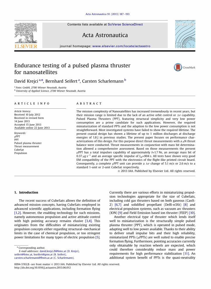
Fig. 3. Typical current pulse during discharge.
D. Krejci et al. / Acta Astronautica 91 (2013) 187–193 189
up to 3 kA, which then ablates, dissociates, ionizes andaccelerates the propellant.
In Fig. 3 the typical current pulse during discharge isshown for standard-shape mPPT with different width-to-gap aspect ratios. Due to the encapsulated mPPT design andits fixed assembly on the PCB, the discharge characteristicscould not be determined in the scope of this work, butbecause of similar geometric dimensions and the sameelectrical setup, similar results can be expected.
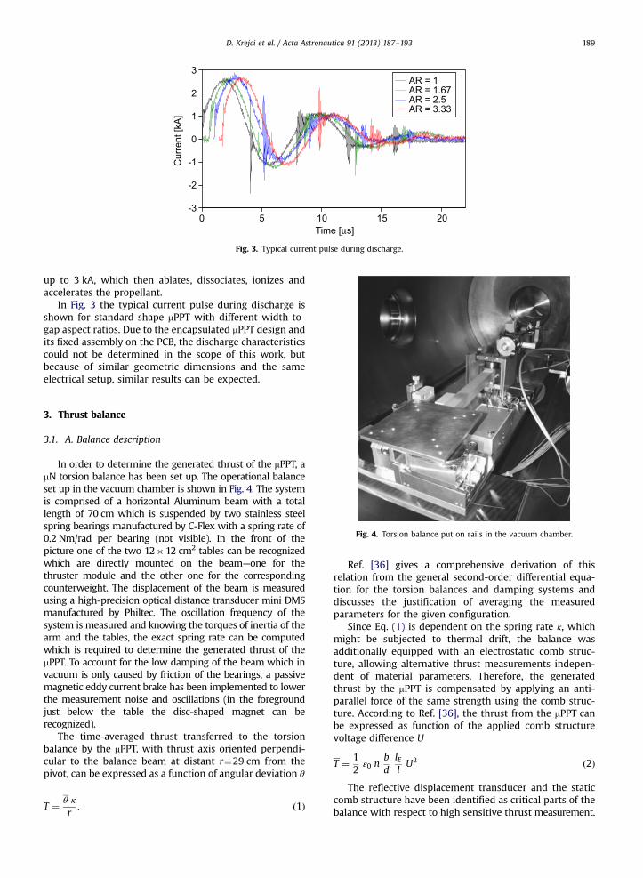
Fig. 4. Torsion balance put on rails in the vacuum chamber.
3. Thrust balance
3.1. A. Balance description
In order to determine the generated thrust of the mPPT, amN torsion balance has been set up. The operational balanceset up in the vacuum chamber is shown in Fig. 4. The systemis comprised of a horizontal Aluminum beam with a totallength of 70 cm which is suspended by two stainless steelspring bearings manufactured by C-Flex with a spring rate of0.2 Nm/rad per bearing (not visible). In the front of thepicture one of the two 12�12 cm2 tables can be recognizedwhich are directly mounted on the beam—one for thethruster module and the other one for the correspondingcounterweight. The displacement of the beam is measuredusing a high-precision optical distance transducer mini DMSmanufactured by Philtec. The oscillation frequency of thesystem is measured and knowing the torques of inertia of thearm and the tables, the exact spring rate can be computedwhich is required to determine the generated thrust of themPPT. To account for the low damping of the beam which invacuum is only caused by friction of the bearings, a passivemagnetic eddy current brake has been implemented to lowerthe measurement noise and oscillations (in the foregroundjust below the table the disc-shaped magnet can berecognized).
The time-averaged thrust transferred to the torsionbalance by the mPPT, with thrust axis oriented perpendi-cular to the balance beam at distant r¼29 cm from thepivot, can be expressed as a function of angular deviation θ
T ¼ θ κ
r: ð1Þ
Ref. [36] gives a comprehensive derivation of thisrelation from the general second-order differential equa-tion for the torsion balances and damping systems anddiscusses the justification of averaging the measuredparameters for the given configuration.
Since Eq. (1) is dependent on the spring rate κ, whichmight be subjected to thermal drift, the balance wasadditionally equipped with an electrostatic comb struc-ture, allowing alternative thrust measurements indepen-dent of material parameters. Therefore, the generatedthrust by the mPPT is compensated by applying an anti-parallel force of the same strength using the comb struc-ture. According to Ref. [36], the thrust from the mPPT canbe expressed as function of the applied comb structurevoltage difference U
T ¼ 12ε0 n
bd
lElU2 ð2Þ
The reflective displacement transducer and the staticcomb structure have been identified as critical parts of thebalance with respect to high sensitive thrust measurement.
D. Krejci et al. / Acta Astronautica 91 (2013) 187–193190
Therefore, proper performance of these crucial componentshas been validated. The accurate operation of the reflectivedisplacement transducer was verified with the aid of a Key-ence LC-2400W laser displacement meter. No malfunction orunexpected deviations have been detected. In addition, mag-netic deflection has been used to validate the electrostaticcomb structure since only small direct currents are used andno high voltage is needed which may be a potential source ofmeasurement errors due to unmeant static charging.
3.2. B. Balance accuracy
The optical displacement sensor uncertainty was deter-mined using a mirror at mechanically fixed distance to thesensor face. The resulting measurement noise and drift of thereflective displacement sensor and the measurement electro-nics are listed in Table 1. The noise and drift of the overall,fully equipped, thrust balance was determined at vacuumoperation conditions for a chamber pressure below 5�10−7 mbar after 48 h in vacuum conditions in order to achievethermal equilibrium and to rule out outgassing effects.
The balance response time was determined by applyinga step force of 100 mN to the fully equipped thrust balanceusing the electrostatic comb. The response time, defined asthe time elapsed from 10% to 90% of the final deflectionwas found to be 1.6 s. The natural frequency of the balanceis therefore 0.6 Hz but it strongly depends on the weightsput on the tables.
4. Test facility and balance operation
For thrust measurements, the mPPTs were pulsed atthree different frequencies of 1/3 Hz, 1/6 Hz and 1/9 Hz
Table 1Balance accuracy.
Noise [mNrms] Drift [nN s−1]
Displacement sensor 0.07 1.3Balance total 0.37 2.0
-1
0
1
2
3
4
5
0Tim
Thru
st [µ
N]
50
Fig. 5. Typical thrust measurem
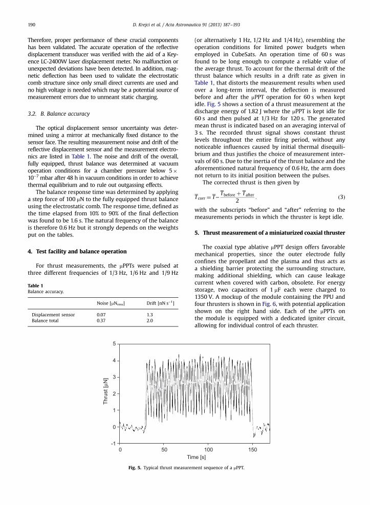
(or alternatively 1 Hz, 1/2 Hz and 1/4 Hz), resembling theoperation conditions for limited power budgets whenemployed in CubeSats. An operation time of 60 s wasfound to be long enough to compute a reliable value ofthe average thrust. To account for the thermal drift of thethrust balance which results in a drift rate as given inTable 1, that distorts the measurement results when usedover a long-term interval, the deflection is measuredbefore and after the mPPT operation for 60 s when keptidle. Fig. 5 shows a section of a thrust measurement at thedischarge energy of 1.82 J where the mPPT is kept idle for60 s and then pulsed at 1/3 Hz for 120 s. The generatedmean thrust is indicated based on an averaging interval of3 s. The recorded thrust signal shows constant thrustlevels throughout the entire firing period, without anynoticeable influences caused by initial thermal disequili-brium and thus justifies the choice of measurement inter-vals of 60 s. Due to the inertia of the thrust balance and theaforementioned natural frequency of 0.6 Hz, the arm doesnot return to its initial position between the pulses.
The corrected thrust is then given by
Tcorr ¼ T−Tbefore þ Tafter
2: ð3Þ
with the subscripts “before” and “after” referring to themeasurements periods in which the thruster is kept idle.
5. Thrust measurement of a miniaturized coaxial thruster
The coaxial type ablative mPPT design offers favorablemechanical properties, since the outer electrode fullyconfines the propellant and the plasma and thus acts asa shielding barrier protecting the surrounding structure,making additional shielding, which can cause leakagecurrent when covered with carbon, obsolete. For energystorage, two capacitors of 1 mF each were charged to1350 V. A mockup of the module containing the PPU andfour thrusters is shown in Fig. 6, with potential applicationshown on the right hand side. Each of the mPPTs onthe module is equipped with a dedicated igniter circuit,allowing for individual control of each thruster.
e [s]100 150
ent sequence of a mPPT.

Fig. 6. mPPT EBB module for CubeSats with four independently controllable thrusters and application example (CubeSat structure by Pumpkin, Inc.).
0
5
10
15
20
0
5
10
15
20
25
0.5
Impu
lse
Bit [
µNs]
Forc
e [ µ
N]
Energy [J]
Force, 0.5HzForce, 0.25HzForce, 1.0HzAverage Impulse Bit
0.7 0.9 1.1 1.3 1.5
Fig. 7. Averaged impulse bit for coaxial annular electrode configuration.
D. Krejci et al. / Acta Astronautica 91 (2013) 187–193 191
Fig. 7 shows the direct thrust measurements for threedifferent firing frequencies, each repeated three times, andthe resulting mean impulse bit measured as a function ofthe discharge energy. Three different discharge energieswere tested by varying the capacitor charging voltage. Ascan be seen, in this energy and discharge frequency range,the impulse bit determination is independent from dis-charge frequency, only showing minor effects of increasedthermal load for increased firing frequencies. The barsindicate the deviation between the single measurementsand do not correspond to the total thrust measurementerror. Further measurements will be necessary in order todetermine the temperature increase of the PPT head forvarious ignition frequencies.
5.1. A. Lifetime thrust measurement
Lifetime tests have been performed using a coaxial typemPPT incorporated into the PPU module. The entire thrus-ter module was mounted on the balance and fired at1/3 Hz continuously to simulate CubeSat operational con-ditions with an average power consumption of less than1 W.
Thrust measurements using the test proceduredescribed before were conducted at intervals of 2 h, orapproximately 2400 ignitions. A long duration test includ-ing thrust measurement was conducted for a total of
4.2�105 discharges. The resulting impulse bit measuredas function of the number of ignitions is shown in Fig. 8.
To avoid the increasing complexity of a moving pro-pellant in the highly miniaturized design employed, thepropellant was not repositioned as in the case of standardPPT designs, in which the propellant front face position iskept constant. Therefore, ablation of the propellant leadsto recession of the propellant face relative to the thrusterelectrodes, prolonging the acceleration chamber. Thedegradation of thrust as already been observed in previousdesigns [42] is traced back to this recession of propellant.The accumulated impulse delivered by the thruster wasdetermined to I¼ 1:7 N s for 4.2�105 discharges. Assum-ing a standard 1-unit CubeSat with a maximum mass of1.33 kg, a propulsion unit containing four thruster headswould be able to deliver a Δv change of Δv≈5:1 m=s,enabling drag make-up maneuvers, formation flight andconstellation maintenance [37–41]. In a realistic scenarioconcerning volume and power budgets available, thethruster module will most likely be employed in a 2- or3-unit CubeSat architecture, with accordingly reducedvelocity changes delivered to the satellite of Δv≈2:6m=sor Δv≈1:7m=s respectively, again assuming a mass of1.33 kg per CubeSat unit. However, long duration testsperformed without thrust measurements showed success-ful thruster operation up to 106 discharges, thereforesignificantly increasing the total impulse per thruster andthe corresponding Δv change.

0
5
10
15
0Number of ignitions [-]
Impu
lse
bit [
µNs]
·103100 200 300 400
Fig. 8. Long duration thrust measurement of mPPT.
00.10.20.30.40.50.60.70.80.9
1
0
mas
s bi
t [µg
/dis
char
ge]
Number of ignitions [-]·103100 200 300 400 500 600 700
Fig. 9. Long-term mass bit measurement of mPPT.
D. Krejci et al. / Acta Astronautica 91 (2013) 187–193192
Disassembly of the TEFLONs propellant bar for weightmeasurements and mass bit determination respectivelywas not possible due to the fashion the mPPT is assembledwithin the propulsion module. Therefore, mass bit deter-mination was performed in a separate long duration testfor an identical mPPT without direct attachment of themPPT to the PPU module, allowing easy disassembling andweight determination of the propellant. This methodimproved the accuracy of the measurement compared topast results [43]. In this configuration, mass bit determina-tion was performed by gravimetric weight determinationof the propellant before and after the test interval. Allweight measurements have been conducted after storageof the propellant under ambient conditions for 24 h toaccount for atmospheric humidity intake. The resultingmass bit values (shown in Fig. 9) are therefore mean valuesaveraged over the number of discharges of the determina-tion interval. As in the case of the impulse bit, the recess ofthe propellant surface leads to a degradation of the massbit. Although the different ways of connecting the mPPT tothe PPU in the case of thrust and mass bit measurementsintroduce an unknown error in the electrical circuit para-meters of the system, the combination of the data pre-sented in Figs. 8 and 9 allows an estimation of the averagespecific impulse achieved for the mPPT configurationemployed. The mean specific impulse averaged over4.2�105 discharges becomes Isp¼9047212 s.
The specific impulse measured is found in the lowerregion of range of specific impulse expected for this type ofthruster which is anticipated considering the given min-iaturization and low energy operation [44]. This translatesdirectly, using a time-averaged mass bit given in Fig. 9 andbasic energy relations, into an initial efficiency of �3.9%which decays to 1.1% after 1,00,000 ignitions and reacheslower values of 0.7% after succeeding 3,00,000 ignitions.These values are located near the lower end of expectedefficiency range for this type of thruster.
6. Conclusion
The pulsed plasma thruster is a candidate propulsiontechnology for miniaturization to meet the stringentrequirements posed by nanosatellites. These miniaturiza-tion requirements especially pose difficulties regarding thereliability and lifetime of such miniaturized thrusters. Thecurrent paper presents a highly miniaturized pulsedplasma thruster in recessive ablative coaxial configurationfor low power operation. The thruster was characterizedand its performance in long duration tests was manufac-tured in-house and investigated. The thruster was incor-porated in a fully operational propulsion unit containingthe PPU and up to four thrusters, and thrust was measuredthroughout a period of 4:2� 105 ignitions. Direct thrustmeasurement of the thruster was performed using adedicated thrust balance, able to resolve mN forces. Totalimpulses delivered throughout the lifetime test weredetermined to be foI≈1:7 N sr one thruster. For the minia-turized thruster module presented, which comprises fourthrusters, this amounts to a Δv change, based on a 1-unitCubeSat, of Δv≈5:1m=s, and correspondingly decreasedvalues of Δv≈2:6m=s and Δv≈1:7m=s for 2-unit and 3-unitCubeSats respectively, based on a satellite mass of 1.33 kgper CubeSat unit. Minimum discrete impulse bits, neces-sary for fine attitude control, were measured toIbit≈10 mN s, decreasing to Ibit≈3:5 mN s for increasedoperational lifetime.
Long duration mass bit measurement was performedover the test duration of 6:9� 105 ignitions. This testshowed degradation in mass bit with increasing totalnumber of discharges corresponding to impulse bit degra-dation. The combined data allowed for an estimate of theachieved specific impulse over the entire test period ofIsp¼9047212 s for the low power, miniaturized thrusterconfiguration.
The thruster module described and used for testing inthis paper allows the individual control of each of the fourthrusters, using four separate ignition circuits, allowing forindividual change on discharge frequency and thus thrustproduced. The ability to individually address each thrusterallows for flexible control in case of thrust deviation of asingle thruster head by modifying the discharge frequencyof such a thruster, maintaining a uniform thrust, if neces-sary. The discharge frequencies achieved by the fourthrusters within the module will be limited by the powerbudget delivered by the CubeSat only.
The mPPT presented and investigated in this work istherefore found capable of providing reliable autonomous
D. Krejci et al. / Acta Astronautica 91 (2013) 187–193 193
propulsion for Nanosatellites, potentially increasing thesatellites mission performance.
Acknowledgements
This project was funded by the Austrian ResearchPromotion Agency (FFG) within the framework of AustrianSpace Applications Program (ASAP).
References
[1] P.P. Sundaramoorthy, E. Gill, C.J.M. Verhoeven, Systematic identifica-tion of applications for a cluster of femto-satellites, in: Proceedingsof the 61st International Astronautical Congress, IAC-10.B4.4.8,Prague, CZ, 2010.
[2] M. Balan, M. Piso, M. Trusculescu, C. Dragasanu, A., Pandele, CubeSatformation flying: a suitable platform for space situational awarenessapplications, in: Proceedings of the 61st International AstronauticalCongress, CZ, IAC-10.B4.4.1, Prague, CZ, 2010.
[3] J. Bouwmeester, J. Guo, Survey of worldwide pico- and nanosatellitemissions, distributions and subsystem technology, Acta Astronaut.67 (7–8) (2010) 854–862.
[4] D. Selva, D. Krejci, A survey and assessment of the capabilities ofCubeSats for Earth observation, Acta Astronaut. 74 (2012) 50–68.
[5] K. Woellert, P. Ehrenfreund, A.J. Ricco, H. Hertzfeld, CubeSats: cost-effective science and technology platforms for emerging and devel-oping nations, Adv. Space Res. 47 (4) (2011) 663–684.
[6] D. Rankin, D.D. Kekez, R.E. Zee, F.M. Pranajaya, D.G. Foisy,A.M. Beattie, The CanX-2 nanosatellite: Expanding the scienceabilities if nanosatellites, Acta Astronaut. 57 (2–8) (2005) 167–174.
[7] K. Sarde, S. Eagleson, E. Caillibot, C. Grant, D. Kekez, F. Pranajaya,R.E. Zee, Canadian advanced nanospace experiment 2: scientific andtechnological innovation on a three-kilogram satellite, Acta Astro-naut. 59 (1–5) (2006) 236–245.
[8] S. de Jong, E. Maddox, G.J. Vollmuller, C.A.H. Schurbiers, R.A.C.M.M.van Swaaij, W.J. Ubbels, R.J. Hamann, The Delfi-n3Xt nanosatellite:space weather research and qualification of microtechnology, in:Proceedings of the 59th International Astronautical Congress, Glas-gow, UK, 2008.
[9] J. Schein, A. Gerhan, F. Rysanek, M. Krishnan, Vacuum arc thrusterfor CubeSat propulsion, in: Proceedings of the 28th InternationalElectric Propulsion Conference, IEPC-0276, Toulouse, Fr, 2003.
[10] C. Scharlemann, GRASP-Analysis of green propellant candidates, in:Proceedings of the 62nd International Astronautical Congress, IAC-11-C4.1.6, Cape Town, South Africa, 2011.
[11] M. Martinez-Sanchez, J.E. Pollard, Spacecraft electric propulsion—anoverview, AIAA J. Propul. Power 14 (5) (1998) 688–699.
[12] R.L. Burton, P.J. Turchi, Pulsed plasma thruster, AIAA J. Propul. Power14 (5) (1998) 716–734.
[13] A. Valdes, K. Khorasani, A pulsed plasma thruster fault detection andisolation strategy for formation flying satellites, Appl. Soft Comput.10 (3) (2010) 746–758.
[14] R. Vondra, K. Thomassen, A. Solbes, A. Pulsed, Electric thruster forsatellite control, Proc. IEEE 59 (2) (1971) 271–277.
[15] R.J. Vondra, K.I. Thomassen, Flight qualified pulsed electric thrusterfor satellite, J. Spacecr. Rockets 11 (9) (1974) 613–617.
[16] R.J. Cassady, N.J. Meckel, W.A. Hoskins, R.M. Myers, S.R. Oleson,M. McGuire, Pulsed plasma thruster systems for spacecraft attitudecontrol, in: Proceedings of the 10th AIAA/USU Conference on SmallSatellites, 1996.
[17] S.W. Benson, L. Arrington, W.A. Hoskins, N.J. Meckel, Development ofa PPT for the EO-1 spacecraft, in: Proceedings of the 35th AIAA/ASME/SAE/ASEE Joint Propulsion Conference, AIAA-99-2276, LosAngeles, California, 1999.
[18] A. Nawaz, M. Auweter-Kurtz, G. Herdrich, H.L. Kurtz, Investigationand optimization of an instationary MPD thruster at IRC, in:Proceedings of the 29th International Electric Propulsion Confer-ence, IEPC-2005-208, Princeton, NJ, 2005.
[19] N.A. Gatsonis, R. Eckman, X. Yin, E.J. Pencil, R.M. Myers, Experi-mental investigations and numerical modeling of pulsed plasmathruster plumes, J. Spacecr. Rockets 38 (3) (2001) 454–464.
[20] M. Coletti, F. Guarducci, S.B. Gabriel, A micro PPT for CubeSatapplication: design and preliminary experimental results, ActaAstronaut. 69 (2011) 200–208.
[21] J. Aoyagi, M. Mukai, Y. Kamishima, T. Sasaki, K. Shintani,H. Takegahara, T. Wakizono, M. Sugiki, Total impulse improvementof coaxial pulsed plasma thruster for small satellite, Vacuum 83 (1)(2009) 72–76.
[22] E. Stuhlinger, Ion Propulsion for Space Flight, McGraw-Hill BookCompany, New York, 13–19.
[23] E. Choueiri, T. Markusic, J. Berkery, J., Cooley, Physics and Dynamicsof Current Sheets in Pulsed Plasma Thrusters, AFOSR-F49620-01-1-0052, October 2001.
[24] J.W. Berkery, E.Y. Choueiri, Canted current sheet mass leakage andits impact on pulsed plasma thruster performance, in: Proceedingsof the 40th AIAA/ASME/SAE/ASEE Joint Propulsion Conference &Exhibit, AIAA-2004-3463, Fort Lauderdale, Florida, July 2004.
[25] P. Shaw, V. Lappas, Modeling of a Pulsed Plasma Thruster, SimpleDesign, Complex Matter, Space Propulsion 2010, San Sebastian,Spain, 26.4.2010.
[26] M. Keidar, I. Boyd, F. Gulczinski, E. Antonsen, G. Spanjers, Analysis ofTeflon surface charring and near field plume of a Micro- PulsedPlasma Thruster, in: Proceedings of the 27th International ElectricPropulsion Conference, IEPC-01-155, Pasadena, CA, October 2001.
[27] M. Keidar, I.D. Boyd, I.I. Beilis, On the model of Teflon ablation in anablation-controlled discharge, J. Phys. D: Appl. Phys. 34 (2001)1675–1677.
[28] R.G. Jahn, Physics of Electric Propulsion, McGraw-Hill, Inc., NewYork, 1968 (Chapter 9).
[29] W.J. Guman, Pulsed Plasma Technology in Microthrusters, FairchildHiller Corp., AFAPL-TR-68-132, Farmingdale, NY, November 1968.
[30] J.K. Ziemer, E.Y. Choueiri, Scaling laws for electromagnetic pulsedplasma thrusters, Plasma Sour. Sci. Technol. 10 (3) (2001) 395–405.
[31] P.V. Shaw, V.J. Lappas, Mathematical modeling of high efficiencypulsed plasma thrusters for microsatellites, in: Proceedings of the57nd International Astronautical Congress, IAC-06-C4.P.4, Valencia,Spain, 2006.
[32] D. Krejci, C. Scharlemann, Analytic model for the assessment of theelectrode configuration of a mPPT, in: Proceedings of the 45th AIAA/ASME/SAE/ASEE Joint Propulsion Conference & Exhibit, AIAA 2009-5279, Denver, Colorado, August 2009.
[33] D.D. Laperriere, N.A. Gatsonis, M.A. Demetriou, Elechtromechanicalmodeling of applied field micro pulsed plasma thrusters, in:Proceedings of the 41st AIAA/ASME/SAE/ASEE Joint PropulsionConference & Exhibit, AIAA 2005-4077, Tucson, Arizona, July 2005.
[34] C.M. Brito, A.A. Elaskar, H.H. Brito, N.R. Paoletti, Zero-dimensionalmodel for preliminary design of ablative pulsed plasma teflonthrusters, J. Propul. Power 20 (6) (2004) 970–977.
[35] A. Nawaz, R. Albertoni, M. Auweter-Kurtz, Thrust efficiency optimi-zation of the pulsed plasma thruster SIMP-LEX, Acta Astronaut. 67(3–4) (2010) 440–448.
[36] D. Krejci, B. Seifert, Miniaturized pulsed plasma thrusters forCubeSats: modelling and direct thrust measurements, in: Proceed-ings of the 61st International Astronautical Congress, IAC-10.E2.1.5,Prague, CZ, September 2010.
[37] E.M.C. Kong, D.W. Miller, Optimal spacecraft reorientation for earthorbiting clusters: applications to Techsat 21, Acta Astronaut. 53 (11)(2003) 863–877.
[38] H.J. Königsmann, J.T. Collins, S. Dawson, J.R. Wertz, Autonomousorbit maintenance system, Acta Astronaut. 39 (9–12) (1996) 977985.
[39] S. Corna, J.C. Bastante, F. Jubineau, Design and operations of a multi-satellite system for the cross-scale mission concept, Acta Astronaut.63 (1–4) (2008) 258–279.
[40] J.A. Kéchichian, Analysis and implementation of in-plane station-keeping of continuously perturbed Walker constellations, ActaAstronaut. 65 (11–12) (2009) 1560–1667.
[41] S. D’Amico, O. Montenbruck, Proximity operations of formation-flying spacecraft using an eccentricity/inclination vector separation,J. Guidance Control Dyn. 29 (3) (2006) 554–563.
[42] D. Krejci, B. Seifert, C. Scharlemann, Thrust measurement of a micropulsed plasma thruster for Cubestats, in: Proceedings of the 1st IAAConference on University Satellite Missions and CubeSat Workshop,Rome, January 2011.
[43] C. Scharlemann, M. Tajmar, I..Vasiljevich, N. Buldrini, D. Krejci,B. Seifert, Propulsion for nanosatellites, in: Proceedings of the32nd International Electric Propulsion Conference, Wiesbaden, 2011.
[44] J.A. Pobst, G.G. Spanjers, I.J. Wysong, J.B. Malak, Basic Research inElectric Propulsion Part I: Pulsed Plasma Thruster Propellant Effi-ciency and Contamination. Part II: Arcjet Remote Plume Measure-ment and Hydrogen Density, Technical Report, AD-A408488; AFRL/PRS-TR-97-3027.