emujc series - wattswater.de€¦ · switch for setting the actuator action: da = direct action,...
TRANSCRIPT

WattsIndustries.com
EMUJC Series Electronic actuator
Technical Data Sheet
2
Watts Water Technologies, Inc.
2
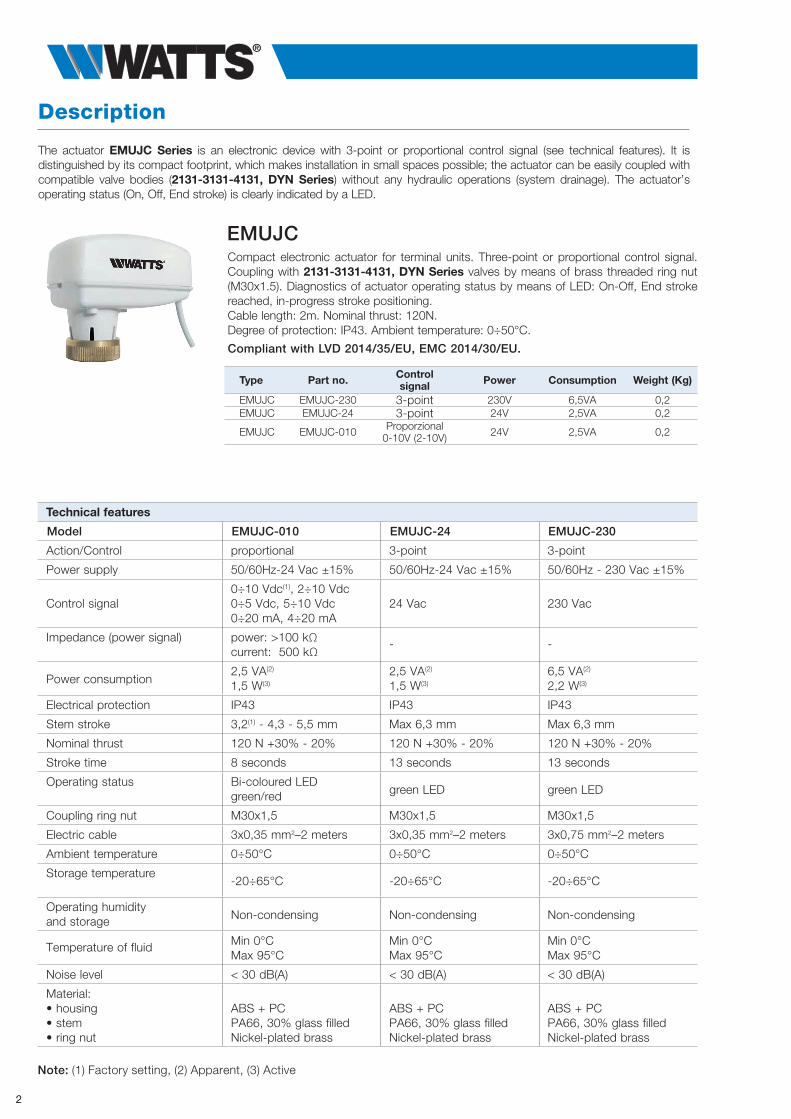
Compact electronic actuator for terminal units. Three-point or proportional control signal. Coupling with 2131-3131-4131, DYN Series valves by means of brass threaded ring nut (M30x1.5). Diagnostics of actuator operating status by means of LED: On-Off, End stroke reached, in-progress stroke positioning.Cable length: 2m. Nominal thrust: 120N.Degree of protection: IP43. Ambient temperature: 0÷50°C.
Compliant with LVD 2014/35/EU, EMC 2014/30/EU.
EMUJC
Type Part no. Control signal Power Consumption Weight (Kg)
EMUJC EMUJC-230 3-point 230V 6,5VA 0,2EMUJC EMUJC-24 3-point 24V 2,5VA 0,2
EMUJC EMUJC-010 Proporzional0-10V (2-10V) 24V 2,5VA 0,2
Technical features
Model EMUJC-010 EMUJC-24 EMUJC-230
Action/Control proportional 3-point 3-point
Power supply 50/60Hz-24 Vac ±15% 50/60Hz-24 Vac ±15% 50/60Hz - 230 Vac ±15%
Control signal0÷10 Vdc(1), 2÷10 Vdc0÷5 Vdc, 5÷10 Vdc0÷20 mA, 4÷20 mA
24 Vac 230 Vac
Impedance (power signal) power: >100 kΩcurrent: 500 kΩ
- -
Power consumption2,5 VA(2)
1,5 W(3)
2,5 VA(2)
1,5 W(3)
6,5 VA(2)
2,2 W(3)
Electrical protection IP43 IP43 IP43
Stem stroke 3,2(1) - 4,3 - 5,5 mm Max 6,3 mm Max 6,3 mm
Nominal thrust 120 N +30% - 20% 120 N +30% - 20% 120 N +30% - 20%
Stroke time 8 seconds 13 seconds 13 seconds
Operating status Bi-coloured LEDgreen/red green LED green LED
Coupling ring nut M30x1,5 M30x1,5 M30x1,5
Electric cable 3x0,35 mm2–2 meters 3x0,35 mm2–2 meters 3x0,75 mm2–2 meters
Ambient temperature 0÷50°C 0÷50°C 0÷50°C
Storage temperature -20÷65°C -20÷65°C -20÷65°C
Operating humidity and storage Non-condensing Non-condensing Non-condensing
Temperature of fluid Min 0°CMax 95°C
Min 0°CMax 95°C
Min 0°CMax 95°C
Noise level < 30 dB(A) < 30 dB(A) < 30 dB(A)
Material:• housing• stem• ring nut
ABS + PCPA66, 30% glass filledNickel-plated brass
ABS + PCPA66, 30% glass filledNickel-plated brass
ABS + PCPA66, 30% glass filledNickel-plated brass
Note: (1) Factory setting, (2) Apparent, (3) Active
The actuator EMUJC Series is an electronic device with 3-point or proportional control signal (see technical features). It is distinguished by its compact footprint, which makes installation in small spaces possible; the actuator can be easily coupled with compatible valve bodies (2131-3131-4131, DYN Series) without any hydraulic operations (system drainage). The actuator’s operating status (On, Off, End stroke) is clearly indicated by a LED.
Description

3
Watts Water Technologies, Inc.
3
ActionWhen the actuator is powered between terminals 1 and 2, the stem extends. When power is removed, the actuator remains in position. When the actuator is powered between terminals 1 and 3, the stem retracts and when the signal is removed, the actuator remains in position. On the other hand, if the actuator remains powered, it stops automatically about 90 seconds after reaching the end stroke position.
Models with three-point control (EMUJC-230 and EMUJC-24)
Fs
Fm
A AB
B B
Fig.1
Actuator - valve coupling by means of threaded ring nut
End strokeIf the signal is continuously applied in the same direction, every 2 hours the actuator starts up for about 90 seconds (in keeping with the signal direction applied), to confirm the end stroke position.
Check of operating statusModels with three-point control are fitted with green LEDs to indicate the operating status:
LED Signal Meaning
Off Actuator not powered
Flashing green Stem moving or Confirmation of end stroke position
Steady green End stroke position reached
Action EMUJC-230 cable colour EMUJC-24 cable colour Stem movement
terminal 1terminal 2
BlueBrown
BlackRed
The stem extends
terminal 1terminal 3
BlueOrange
BlackOrange
The stem retracts
The electronic actuators EMUJC Series, coupled with the valves 2131-3131-4131, DYN Series, are used in heating and/or air-conditioning systems to control the heat emission of the single terminal units.
Application
Operation
The operation of the EMUJC Series actuator is based on the rotation of a shaft driven in either direction by a set of gears. The latter are, in turn, driven by a bidirectional synchronous motor through a magnetic coupling which limits the torque transmitted and therefore also the linear output force. The actuator and valve body (Fig.1) are coupled by means of a threaded ring nut . The movement of the actuator is transmitted to the stem of the valve by axial contact and is kept constant by means of a spring situated inside the valve body. In this way, the valve opening and closing forces are obtained, in one direction, through the thrust exerted by the actuator (Fs opens way B-AB, Fig.2) and, in the other direction, through the force of the spring (Fm opens way A-B, Fig.2) situated inside the valve itself. The valve remains open if the actuator is removed from the valve body.
Fig.2

4
Watts Water Technologies, Inc.
4
ActionWhen the control signal increases (from 0 to 10 V) in Direct Action (DA) configuration the stem extends, and in Reverse Action (RA) configuration, the stem retracts.When the control signal decreases (from 10 to 0V) in Direct Action (DA) configuration the stem retracts, and in Reverse Action (RA) configuration, the stem extends
Model with proportional control (EMUJC-010)
Action Control signal Stem movement
Direct Action (DA) 0÷10 Vdc The stem extends
10÷0 Vdc The stem retracts
Reverse Action (RA)0÷10 Vdc The stem retracts
10÷0 Vdc The stem extends
End strokeIf the signal is continuously applied in the same direction, every 2 hours the actuator starts up for about 60 seconds (in keeping with the signal direction applied), to confirm the end stroke position.
Self-calibrationWhen it is powered, the actuator self-calibrates its end stroke position. The actuator drives the stem out for the whole available stroke of the valve until it no longer detects movement of the plug and it memorises its position. At the end of the self-calibration cycle, the actuator positions the stem according to the control signal.
Control segnals
The actuator is set up to receive the following user-selected input control signals:
• 0÷10 Vdc
• 2÷10 Vdc
• 0÷5 Vdc
• 5÷0 Vdc
• 0÷20 mA
• 4÷20 mA
Check of operating statusThe model with proportional control is fitted with a bi-coloured LED (green/red) to indicate the operating status:
LED Signal Meaning
Off Actuator not powered
Flashing green Stem moving or Confirmation of end stroke position
Steady green Position reached
Flashing red Self-calibration cycle
Steady red No input signal (when set at 2÷10V o 4÷20 mA)
5
Watts Water Technologies, Inc.
5
>15 cm
OKNO
OK OK
Max 90 °C Max 90 °C
Fig.3
>15 cm
OKNO
OK OK
Max 90 °C Max 90 °C
>15 cm
OKNO
OK OK
Max 90 °C Max 90 °C
Fig.4 Fig.5
N L1 230VACN L1 230VAC
AC
(-)
(+)
BLUE RED GREY
BLACK RED ORANGE BLACK RED ORANGE BLUE BROWN ORANGE BLU BROWN ORANGE
N L1 230VACN L1 230VAC
AC
(-)
(+)
BLUE RED GREY
BLACK RED ORANGE BLACK RED ORANGE BLUE BROWN ORANGE BLU BROWN ORANGE
N L1 230VACN L1 230VAC
AC
(-)
(+)
BLUE RED GREY
BLACK RED ORANGE BLACK RED ORANGE BLUE BROWN ORANGE BLU BROWN ORANGE
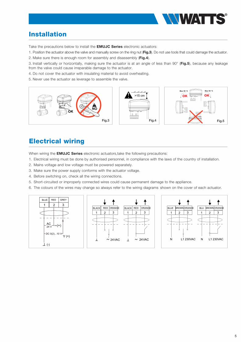
Take the precautions below to install the EMUJC Series electronic actuators:
1. Position the actuator above the valve and manually screw on the ring nut (Fig.3). Do not use tools that could damage the actuator.
2. Make sure there is enough room for assembly and disassembly (Fig.4).
3. Install vertically or horizontally, making sure the actuator is at an angle of less than 90° (Fig.5), because any leakage from the valve could cause irreparable damage to the actuator.
4. Do not cover the actuator with insulating material to avoid overheating.
5. Never use the actuator as leverage to assemble the valve.
Installation
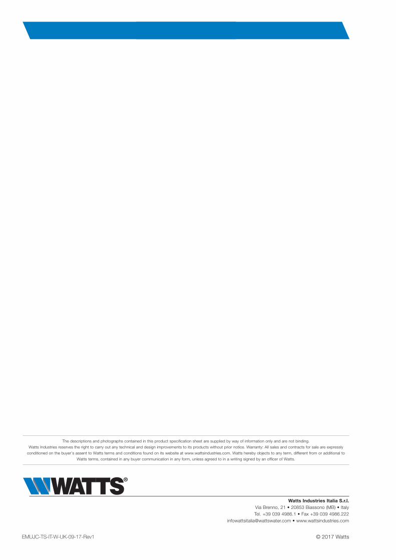
When wiring the EMUJC Series electronic actuators,take the following precautions:
1. Electrical wiring must be done by authorised personnel, in compliance with the laws of the country of installation.
2. Mains voltage and low voltage must be powered separately.
3. Make sure the power supply conforms with the actuator voltage.
4. Before switching on, check all the wiring connections.
5. Short-circuited or improperly connected wires could cause permanent damage to the appliance.
6. The colours of the wires may change so always refer to the wiring diagrams shown on the cover of each actuator.
Electrical wiring

6
Watts Water Technologies, Inc.
6
Dip switch
Switches 1-2-3Switches for setting the control signal. Switch 6 must be selected as a consequence.
Switches 4Switch for setting the actuator action: DA = Direct Action, RA = Reverse Action.
Switches 5Switch for setting the control characteristics.Switch OFF = linear output to use with linear or equal percentage valves.Switch ON = pseudo equal percentage output to use with quick-opening or on/off valves.
Switches 6Switch for setting the type of control signal.Switch OFF = signal voltageSwitch ON = signal currentThis switch must be set on the basis of switches 1, 2 and 3
NOTE: all switches are factory set in the OFF position.
Switch ON - RASwitch OFF - DA
The actuators with three-point control (EMUJC-24 and EMUJC-230) do not need any initial set-up. The proportional actuator (EMUJC-010) can be configured on the basis of the input signal, the desired action and the required stem stroke. The main configurations are shown below. For more information refer to the instruction sheet.
Configuration
DIP SWITCH
1:2:3:
4:5:6:
ACTIONCURVESIGNAL TYPE
COMMAND SIGNAL
RANGE
OFF
0..10VDC0..20m
A
0..5VDC
5..10VDC
2..10VDC4..20m
A
DA RA
LIN Eq%
VDC mA
1 2
34
56
ON
OFFON

7
Watts Water Technologies, Inc.
7
80
60 2049
73.6
M 30 x 1.5
EMUJC
NOTE: the stroke is factory set at 3.2mm
Jumper
The correlation between the positions of the jumper and the stroke of the actuator stem is shown below.
Overall dimensions (mm)
3.2 mm
6
4.3 mm
6
6 mm
6
Specification text
EMUJC SeriesCompact electronic actuator for terminals EMUJC Series WATTS brand. Three-point or proportional control signal. Coupling to the valves by brass threaded nut M30x1.5. Diagnostics of actuator status by LED: On-Off indication, limit switch reached, positioning in progress. Power cable length: 2m. Nominal thrust: 120N. Degree of protection: IP43. Ambient temperature: 0÷50°C. Compliant with LVD 2014/35/EU, EMC 2014/30/EU.
Watts Industries Italia S.r.l.Via Brenno, 21 • 20853 Biassono (MB) • ItalyTel. +39 039 4986.1 • Fax +39 039 4986.222
[email protected] • www.wattsindustries.com
© 2017 Watts
The descriptions and photographs contained in this product specification sheet are supplied by way of information only and are not binding.
Watts Industries reserves the right to carry out any technical and design improvements to its products without prior notice. Warranty: All sales and contracts for sale are expressly
conditioned on the buyer’s assent to Watts terms and conditions found on its website at www.wattsindustries.com. Watts hereby objects to any term, different from or additional to
Watts terms, contained in any buyer communication in any form, unless agreed to in a writing signed by an officer of Watts.
EMUJC-TS-IT-W-UK-09-17-Rev1