emma project update operational concept for a complete a-smgcs · joern jakobi, dlr a-smgcs work...
TRANSCRIPT

Integrated Project of theSixth Framework Programme,
Priority 1.4: Aeronautics and Space,
sponsored by EC, DG TRENContract FP6-503192
Internet: http://www.dlr.de/emma
EMMA Project Update +
Operational Concept for a complete A-SMGCS
Jörn Jakobi, DLR

Joer
n Ja
kobi
, DLR
A-SMGCS Work Shop, Luxembourg, 2005 2
The European Commission funded systematically A-SMGCS implementation projects:
FP4: DEFAMM (1996 – 1999)
FP5: BETA (2000 – 2002)
FP6: EMMA (2004 – 2006)which will pave the way forward to harmonise the implementation of A-SMGCS level 1&2
EMMA2 (2006 – 2008)will consider higher levels of A-SMGCS
Why EMMA

Joer
n Ja
kobi
, DLR
A-SMGCS Work Shop, Luxembourg, 2005 3
Objectives
Harmonisation and Consolidation of level 1&2 Concepts
Verification and Validationof a level 1&2 A-SMGCS
Innovative A-SMGCS-R&D and A-SMGCS-Spin-Offs
Implementation of a level 1&2 A-SMGCS
Harmonised Implementation of A-SMGCS

Joer
n Ja
kobi
, DLR
A-SMGCS Work Shop, Luxembourg, 2005 4
24 Partner, 9 States24 Months Duration
Budget of 16 Mio. Total3 Test Sites
EMMA Consortium
Joer
n Ja
kobi
, DLR
A-SMGCS Work Shop, Luxembourg, 2005 5
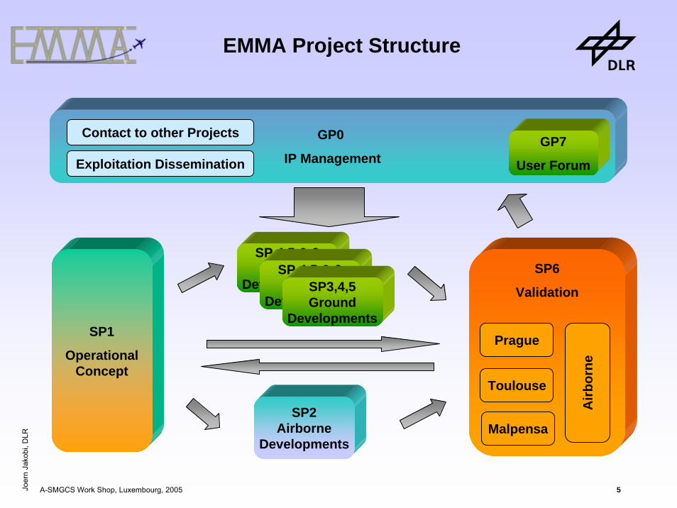
EMMA Project Structure
GP0
IP ManagementExploitation Dissemination
SP1
OperationalConcept
SP 4,5 & 6Ground
Developments
SP2Airborne
Developments
SP6
Validation
Prague
Toulouse
Malpensa
SP 4,5 & 6Ground
DevelopmentsSP3,4,5Ground
Developments
Contact to other Projects GP7
User Forum
Airb
orne

Joer
n Ja
kobi
, DLR
A-SMGCS Work Shop, Luxembourg, 2005 6
Achievements so far (1)
• A harmonised definition of A-SMGCS levels I & II in partnership with Eurocontrol
• Development of algorithm and analysis tool (MOGADOR by CENA/DSNA) to assess surveillance and alerting performance
• Surveillance performance assessment at the biggest European Hub Paris Charles de Gaulle Airport
• Concept for higher-level services, equipment and procedures outlined
• Functional Hazard Assessment (FHA) and Preliminary System SafetyAssessment (PSSA) conducted
• Verification and Validation Methodology harmonised with 3 test sites
• RWY-Incursion Scenarios tested in Real Time Simulation for Prague and Milan Malpensa and Systems tuned to operational needs

Joer
n Ja
kobi
, DLR
A-SMGCS Work Shop, Luxembourg, 2005 7
Achievements so far (2)
• Cockpit Real Time Simulation performed at Airbus and DLR CockpitSimulator
• Three different MLAT Systems under development– in Toulouse by Thales ATM and
– in Malpensa by SELEX (formerly Alenia Marconi Systems)
– In Prague by ERA under operational use
• ADS-B solutions using 1090ES integrated and under test
• Onboard Guidance planned to demonstrate in– TUD Test Vehicles
– DLR Test Aircraft
– Revenue Aircraft

Joer
n Ja
kobi
, DLR
A-SMGCS Work Shop, Luxembourg, 2005 8
Dissemination of Results
• Consolidate with EUROCONTROL findings
• Consolidate with C-ATM (Co-operative Air Traffic Management)
• Promoted at different international events (FAA-EUROCONTROL ATM Seminar, ATM Symposium, JISSA, CAATS, A-SMGCS workshops)
• Feedback to ICAO to mature Manual on A-SMGCS in partnership with Eurocontrol
• Feed in EMMA2 (as a perfect starting point – same test sites and nearly same partners)
• Feedback to EUROCAE to mature A-SMGCS MASPS
• Co-ordination with other projects (e.g. FLYSAFE, D-TAXI)

Joer
n Ja
kobi
, DLR
A-SMGCS Work Shop, Luxembourg, 2005 9
Ongoing Issues
• Focus in the remaining runtime of EMMA on– Consolidation of concept documents (updates)
– Toulouse and Malpensa Installations
– Operational Tests at Prague and Malpensa
– Shadow Mode Trials at Toulouse
– D-MAN demonstrations at DLR simulator with Prague scenarios
– Analysis of Results
– Recommendation Report
• Consolidate and Disseminate actively the Findings (e.g. EMMA Demonstration Day [Prague, 21st/22nd March 2006], Eurocontrol A-SMGCS group)
• Disseminate flyers and a short video

Integrated Project of theSixth Framework Programme,
Priority 1.4: Aeronautics and Space,
sponsored by EC, DG TRENContract FP6-503192
Internet: http://www.dlr.de/emma
EMMA Operational Concept for a complete A-SMGCS
Joer
n Ja
kobi
, DLR
A-SMGCS Work Shop, Luxembourg, 2005 11
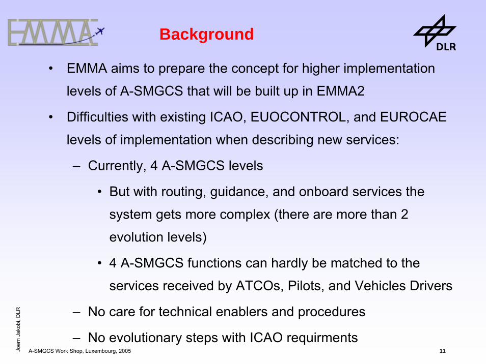
Background
• EMMA aims to prepare the concept for higher implementation
levels of A-SMGCS that will be built up in EMMA2
• Difficulties with existing ICAO, EUOCONTROL, and EUROCAE
levels of implementation when describing new services:
– Currently, 4 A-SMGCS levels
• But with routing, guidance, and onboard services the
system gets more complex (there are more than 2
evolution levels)
• 4 A-SMGCS functions can hardly be matched to the
services received by ATCOs, Pilots, and Vehicles Drivers
– No care for technical enablers and procedures
– No evolutionary steps with ICAO requirments
Joer
n Ja
kobi
, DLR
A-SMGCS Work Shop, Luxembourg, 2005 12
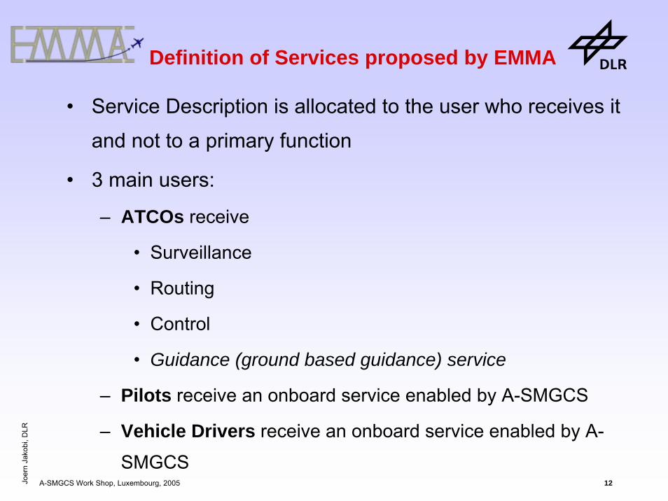
Definition of Services proposed by EMMA
• Service Description is allocated to the user who receives it
and not to a primary function
• 3 main users:
– ATCOs receive
• Surveillance
• Routing
• Control
• Guidance (ground based guidance) service
– Pilots receive an onboard service enabled by A-SMGCS
– Vehicle Drivers receive an onboard service enabled by A-
SMGCS
Joer
n Ja
kobi
, DLR
A-SMGCS Work Shop, Luxembourg, 2005 13
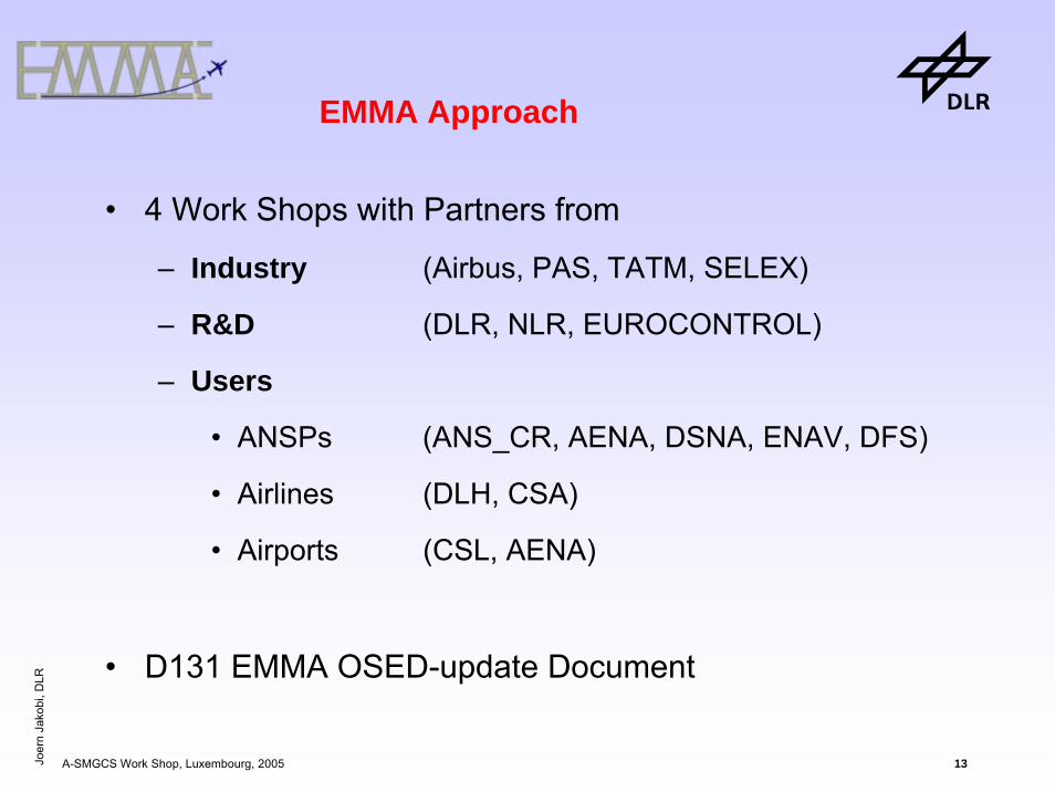
EMMA Approach
• 4 Work Shops with Partners from
– Industry (Airbus, PAS, TATM, SELEX)
– R&D (DLR, NLR, EUROCONTROL)
– Users
• ANSPs (ANS_CR, AENA, DSNA, ENAV, DFS)
• Airlines (DLH, CSA)
• Airports (CSL, AENA)
• D131 EMMA OSED-update Document

Joer
n Ja
kobi
, DLR
A-SMGCS Work Shop, Luxembourg, 2005 14
Definition of Services proposed by EMMA
• When defining a service, technical functions and theirtechnical enablers have to be regarded
• It is an iterative process
– Service technical Enablers
Joer
n Ja
kobi
, DLR
A-SMGCS Work Shop, Luxembourg, 2005 15
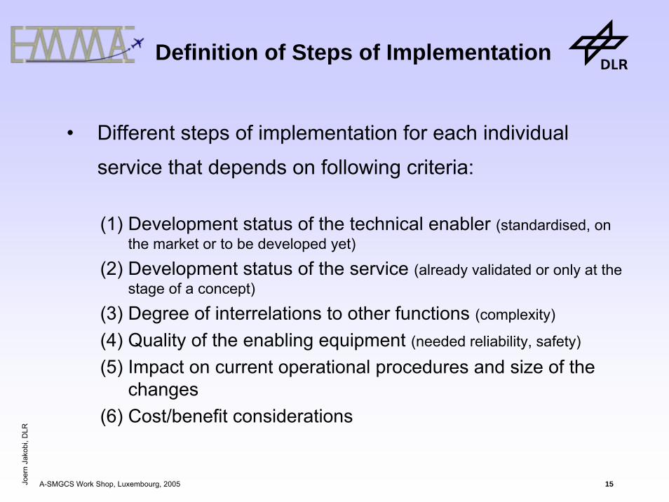
Definition of Steps of Implementation
• Different steps of implementation for each individual
service that depends on following criteria:
(1) Development status of the technical enabler (standardised, on the market or to be developed yet)
(2) Development status of the service (already validated or only at the stage of a concept)
(3) Degree of interrelations to other functions (complexity)
(4) Quality of the enabling equipment (needed reliability, safety)
(5) Impact on current operational procedures and size of the changes
(6) Cost/benefit considerations

Joer
n Ja
kobi
, DLR
A-SMGCS Work Shop, Luxembourg, 2005 16
Definition of Functions and Technical Enablers
ATCO - Surveillance
Function On-board Enabler Ground Enabler
Provide traffic information
•Mode S transponder•ADS-out
•Cooperative sensors (SSR, Mode-S, ADS-B, GNSS)•Non-cooperative sensors (SMR)•Sensor data fusion•Flight information•Vehicle information
Provide traffic context •Aeronautical info server•Meteo data
Interface with ATCOs •HMI component

Joer
n Ja
kobi
, DLR
A-SMGCS Work Shop, Luxembourg, 2005 17
EMMA Surveillance – Service Step 1
Obstacles(whether moving or stationary, having an equivalent radar cross
section of 1 square meter or more)
Non-authorised non-cooperativemovements
(only pos)
Non-authorisedCooperative Movements
(pos & id)
AuthorisedcooperativeMovements
(pos & id)
Intruders
Onlycovered
Area1 Transition Phase:
Authorised but non-cooperativeMovements (only pos) (e.g. GA)
Manoeuvring

Joer
n Ja
kobi
, DLR
A-SMGCS Work Shop, Luxembourg, 2005 18
+ area Transition Phase:Authorised but non-cooperative
Aircraft (only pos) (e.g. GA)Authorisedcooperative
Aircraft(pos & id)
EMMA Surveillance – Service Step 2
Obstacles(whether moving or stationary, having an equivalent radar cross
section of 1 square meter or more)
Non-authorised non-cooperative movements(aircraft and vehicles detected but not authorised and notautomatically
identified)
Non-authorisedCooperative Movements
(aircraft & vehicles identified but not authorised)
AuthorisedcooperativeMovements(aircarft and
vehicles identifiedand authorised)
Intruders
Transition Phase:Authorised but non-coperative Movements (e.g. VFR)
[1] All movements on the manoeuvring have to be authorised by aerodrome controller (compare §7.5.3.2.1, doc4444). With EMMA all authoried movements shall be properly equipped to enable automatic identification. All other movements are intruders or obstacles.
Manoeuvering Apron

Joer
n Ja
kobi
, DLR
A-SMGCS Work Shop, Luxembourg, 2005 19
Obstacles(whether moving or stationary, having an equivalent radar crosssection of 1 square meter or more within designated area where
obstacles can conflict aircraft movements [taxi lanes, active stands])
Non-authorised Vehicles2
AuthorisedCooperative Vehicles2
((pos & id)within designated areas where vehicles can conflict with aircraft
Intruder
[2] In low visibility conditions, when movements are not able to avoid each other, parts of the apron area (taxi lanes, active stands) are used exclusively for authorised movements. In LVO Vehicles operating in these areas must be authorised and equipped. In good visibility conditions vehicles do not have to be controlled on the Apron (compare also ICAO doc 9830 §3.5.16.3).
Transition Phase:Authorised but non-cooperative
Aircraft (e.g. GA)Authorisedcooperative
Aircraft(pos & id)
+ area
EMMA Surveillance – Service Step 3 (+VIS3)
Obstacles(whether moving or stationary, having an equivalent radar cross
section of 1 square meter or more)
Non-authorised non-cooperative movements(aircraft and vehicles detected but not authorised and notautomatically
identified)
Non-authorisedCooperative Movements
(aircraft & vehicles identified but not authorised)
AuthorisedcooperativeMovements(aircarft and
vehicles identifiedand authorised)
Intruders
Transition Phase:Authorised but non-coperative Movements (e.g. VFR)
[1] All movements on the manoeuvring have to be authorised by aerodrome controller (compare §7.5.3.2.1, doc4444). With EMMA all authoried movements shall be properly equipped to enable automatic identification. All other movements are intruders or obstacles.
Manoeuvering Apron

Joer
n Ja
kobi
, DLR
A-SMGCS Work Shop, Luxembourg, 2005 20
Definition of Services StepsATCO - Surveillance
Service Steps
Description
Step 1 • Detection and accurate position of all aircraft, all vehicles, and obstacles
• Identification of all cooperative aircraft and vehicles
Step 2 • Step1 + Detection and identification of all aircrafts
Step 3 • Step2 + • Detection and identification of
all vehicles • Detection of Obstacles
Manoeuvring area
Movement area
Movement area•Vis3 - where manoeuvring a/c may come into conflict with each other or with vehiclesICAO doc 9830 §3.5.16.3
Comments

Joer
n Ja
kobi
, DLR
A-SMGCS Work Shop, Luxembourg, 2005 21
Definition of Functions and Technical Enablers
ATCO - Control
Function On-board Enabler Ground EnablerConflict and Incursion Detection and Alerting
•Surveillance function + alerting algorithm
Conflict Resolution •Resolution algorithm
Support to Communication
•Data Link (point to point)•Onboard HMI component
•Data Link•Ground HMI component
Support to coordination between ATCOs
•Flight Data Management•Electronic Flight Strips

Joer
n Ja
kobi
, DLR
A-SMGCS Work Shop, Luxembourg, 2005 22
Definition of Service StepsATCO - Control
Service Step
Description Comments
Step 1 •Runway Conflict/Incursion detection and alerting
Step 2 •Taxiway Conflict/Incursion detection and alerting
Step 3 •Detection of plan / route deviation•Support to Communication (CPDLC)•ATCO coordination (EFS)
Step 4 •Conflict/Incursion detection and alerting of apron / stand / gateconflicts
Implementation of conflict resolutionadvisorymay be initiated at any step

Joer
n Ja
kobi
, DLR
A-SMGCS Work Shop, Luxembourg, 2005 23
Definition of Functions and Technical Enablers
ATCO - Routing
Function On-board Enabler
Ground Enabler
Manual Routing None •Input Devices + •simple routing algorithm
Semi-automatic Routing None
•Routing algorithm +•Interfaces to external data
Automatic Routing None
•Routing algorithm + •Interfaces to external data•Planning algorithm (SU-time, DMAN)

Joer
n Ja
kobi
, DLR
A-SMGCS Work Shop, Luxembourg, 2005 24
Definition of Service StepsATCO - Routing
Service Steps
Description Comments
Step 1 Manual Routing Manual input of a route supported by the shortest taxi route w.r.t. to local standard routes
Step 2 Semi-automatic Routing Routing service proposes a most suitable route, taking into account control and flight plan information.
Step 3 Automatic Routing Routing service provides route (track) and time information by aid of a planning function.
Step 4

Joer
n Ja
kobi
, DLR
A-SMGCS Work Shop, Luxembourg, 2005 25
Definition of Service StepsATCO – Routing
Efficient taxi route + Start-up time
Source: BETA

Joer
n Ja
kobi
, DLR
A-SMGCS Work Shop, Luxembourg, 2005 26
Definition of Service StepsATCO - Routing
Service Steps
Description Comments
Step 1 Manual Routing Manual input of a route supported by the shortest taxi route w.r.t. to local standard routes
Step 2 Semi-automatic Routing Routing service proposes a most suitable route, taking into account control and flight plan information.
Step 3 Automatic Routing Routing service provides route (track) and time information by aid of a planning function.
Step 4 Automatic Routing + ROP (DMAN)[1]
Planning support is further increased by a departure manager providing optimal runway occupancy times.
Joer
n Ja
kobi
, DLR
A-SMGCS Work Shop, Luxembourg, 2005 27
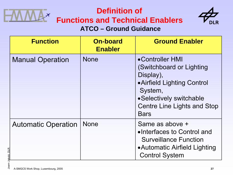
Definition of Functions and Technical Enablers
ATCO – Ground Guidance
Function On-board Enabler
Ground Enabler
Manual Operation None •Controller HMI (Switchboard or Lighting Display),•Airfield Lighting Control System,•Selectively switchableCentre Line Lights and Stop Bars
Automatic Operation None Same as above +•Interfaces to Control and Surveillance Function
•Automatic Airfield Lighting Control System
Joer
n Ja
kobi
, DLR
A-SMGCS Work Shop, Luxembourg, 2005 28
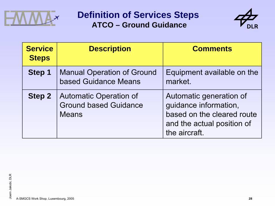
Definition of Services StepsATCO – Ground Guidance
Service Steps
Description Comments
Step 1 Manual Operation of Ground based Guidance Means
Equipment available on the market.
Step 2 Automatic Operation of Ground based Guidance Means
Automatic generation of guidance information, based on the cleared route and the actual position of the aircraft.
Joer
n Ja
kobi
, DLR
A-SMGCS Work Shop, Luxembourg, 2005 29
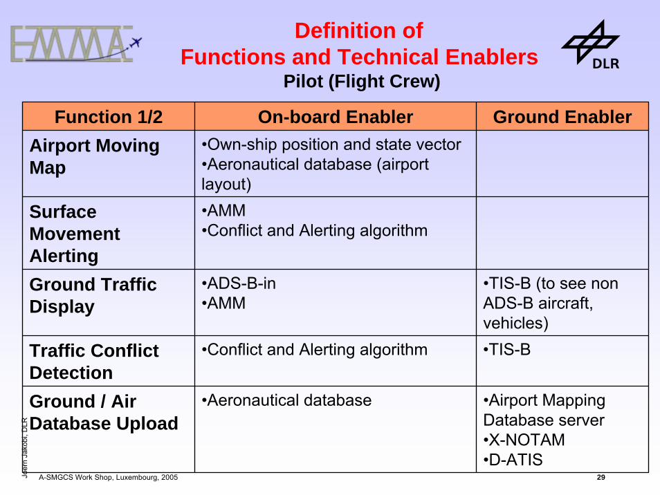
Definition of Functions and Technical Enablers
Pilot (Flight Crew)
Function 1/2 On-board Enabler Ground EnablerAirport Moving Map
•Own-ship position and state vector•Aeronautical database (airport layout)
Surface Movement Alerting
•AMM•Conflict and Alerting algorithm
Ground Traffic Display
•ADS-B-in•AMM
•TIS-B (to see non ADS-B aircraft, vehicles)
Traffic Conflict Detection
•Conflict and Alerting algorithm •TIS-B
Ground / Air Database Upload
•Aeronautical database •Airport Mapping Database server•X-NOTAM•D-ATIS

Joer
n Ja
kobi
, DLR
A-SMGCS Work Shop, Luxembourg, 2005 30
Function 2/2 On-board Enabler Ground Enabler
CPDLC Ground Clearances and Taxi Route Uplink
•CPDLC (DCL, D-Taxi)•Airport Moving Map
•CPDLC•Routing service
Braking and Steering Cues
•Taxi-Route (uplinked or not)•Aeronautical database (airport layout)•B&S algorithm
HUD Surface Guidance
•Taxi Route (uplinked or not)•Own-ship position and state vector•Aeronautical database
Automated Steering
•Taxi Route (uplinked or not)•Own-ship position and state vector•Auto-Pilot for taxiing
Definition of Functions and Technical Enablers
Pilot (Flight Crew)

Joer
n Ja
kobi
, DLR
A-SMGCS Work Shop, Luxembourg, 2005 31
Service Steps
Description Comments
Step 1 •Airport Moving Map•Surface Movement Alerting•Braking and Steering Cue (for landing roll)
•Equipment already available
Step 2 •Ground-Air Database Upload•Ground Traffic Display•Traffic Conflict Detection•CPDLC Ground Clearance and Taxi Route Uplink•Braking and Steering Cue (landing roll and taxi)
•Ground TIS-B + DL needed
Step 3 •HUD Surface Guidance •HUD is already available for approach
Step 4 •Automated Steering •Major changes in equipments and procedures
Definition of Service StepsPilot (Flight Crew)

Joer
n Ja
kobi
, DLR
A-SMGCS Work Shop, Luxembourg, 2005 32
Definition of Functions and Technical Enablers
Vehicle Drivers
Function On-board Enabler Ground EnablerAirport Moving Map •Own-ship position and state
vector•Aeronautical database (airport layout)
Surface Movement Alerting
•AMM•Conflict and Alerting algorithm
Ground Traffic Display
•ADS-B-in•AMM
•TIS-B
Traffic Conflict Detection
•Conflict and Alerting algorithm •TIS-B
Support to Vehicles Operations via data link
•Ground/vehicle datalink •Ground/vehicle datalink

Joer
n Ja
kobi
, DLR
A-SMGCS Work Shop, Luxembourg, 2005 33
Definition of Services StepsVehicle Drivers
Service Steps
Description Comments
Step 1 •Airport Moving Map inlc. alerts
•No ground equipment•Equipment already available
Step 2 •Ground-Air Database Upload•Ground Traffic Display incl. alerts
•Ground TIS-B + DL needed
Step 3 •Dispatch and Guidance via data link

Joer
n Ja
kobi
, DLR
A-SMGCS Work Shop, Luxembourg, 2005 34
Definition of Procedures
• Workshop with Users to discuss by which potential
procedures the services should be applied
• Procedures defined for higher services but still very pre-
matured
• But we need initial procedures to test them in validation
activities (EMMA2)
• Procedures are the core to enable a service to bring
benefit
• Initial procedures used to cluster service steps to
A-SMGCS implementation packages
• EMMA doc D135 - Op. Requirements Doc

Joer
n Ja
kobi
, DLR
A-SMGCS Work Shop, Luxembourg, 2005 35
Logical Interdependencies between EMMA Service Steps
automation - complexity – new procedures
Surveillance Step 1 Step 2 Step 3
Step 1Control Step 2 Step 3
Step 1Routing Step 2 Step 3
Step 1Guidance Step 2
Gro
und
Sys
tem
Step 1Aircraft Step 2 Step 3
enables

Joer
n Ja
kobi
, DLR
A-SMGCS Work Shop, Luxembourg, 2005 36
Expected Steps to each Service
Surveillance
S1id/pos
everything manoeuvering
S2Step 1 +
id/pos a/c in the movement area
S3S2 + id/pos
vehicles movement
area
ControlC1
Conflict RwyC2
Conflict Twy
C3Plan / Route Deviation
C4Conflict Apron
Guidance G1Manual switched ground guidance (e.g. Heathrow)
G2Auto switch
Routing R1Manual
R2Semi-auto
R3Auto (planning)
R4ROP
Aircraft
A1AMM
A2Ground traffic
+ CPDLC
A3HUD
A4Auto
steering
Vehicles V1AMM
V2Ground Traffic
V3Data link
Logical Interdependencies between EMMA Service Steps

Joer
n Ja
kobi
, DLR
A-SMGCS Work Shop, Luxembourg, 2005 37
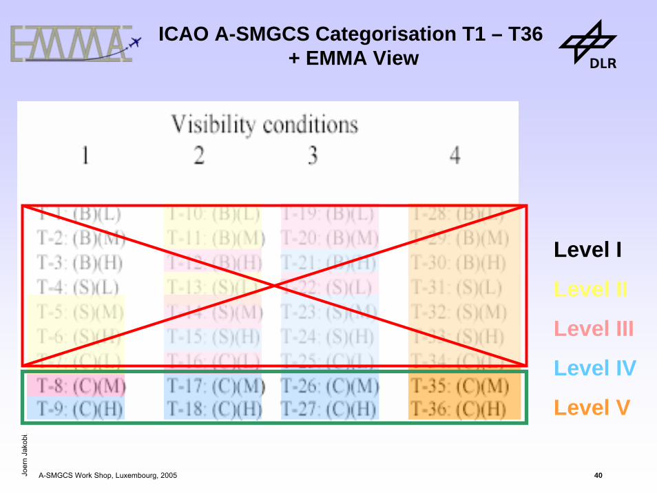
ICAO A-SMGCS Categorisation
1. Visibility Conditions• Vis 1 no impact• Vis 2 ATCO cannot see • Vis 3 Pilots cannot see and avoid (400m < Vis 3 < 75m)• Vis 4 Pilots cannot taxi (< 75m)
2. Traffic Density• Light (L): 0 < movements < 20• Medium (M): 20 < movements < 35• Heavy (H): 35 < movements ∞
3. Aerodrome Layout• Basic (B): = 1 RWY = 1 TWY = 1 Apron• Simple (S): = 1 RWY > 1 TWY > 1 Apron • Complex (C): > 1 RWY > 1 TWY > 1 Apron

Joer
n Ja
kobi
, DLR
A-SMGCS Work Shop, Luxembourg, 2005 38
ICAO implementation levels

Joer
n Ja
kobi
, DLR
A-SMGCS Work Shop, Luxembourg, 2005 39
Level I
Level II
Level III
Level IV
Level V
ICAO A-SMGCS Categorisation T1 – T36
Joer
n Ja
kobi
, DLR
A-SMGCS Work Shop, Luxembourg, 2005 40
Level I
Level II
Level III
Level IV
Level V
ICAO A-SMGCS Categorisation T1 – T36+ EMMA View
Joer
n Ja
kobi
, DLR
A-SMGCS Work Shop, Luxembourg, 2005 41
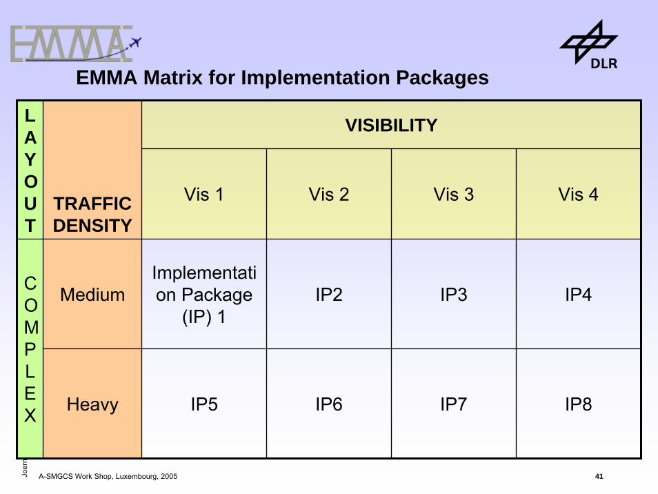
EMMA Matrix for Implementation Packages
VISIBILITYLAYOUT
TRAFFIC DENSITY
Vis 1 Vis 2 Vis 3 Vis 4
MediumImplementation Package
(IP) 1IP2 IP3 IP4
Heavy IP5 IP6 IP7 IP8
COMPLEX

Joer
n Ja
kobi
, DLR
A-SMGCS Work Shop, Luxembourg, 2005 42
ICAO A-SMGCS Definition
A system providing routing, guidance and surveillance for the
control of aircraft and vehicles in order to maintain the
declared surface movement rate under all weather conditions
within the aerodrome visibility operational level (AVOL) while
maintaining the required level of safety.
– SAFETY
– THROUGHPUT

Joer
n Ja
kobi
, DLR
A-SMGCS Work Shop, Luxembourg, 2005 43
Traffic Density Vis 1 Vis 2 Vis 3 Vis 4
Heavy
Optional
Medium
optional
EMMA Matrix for Implementation Packages

Joer
n Ja
kobi
, DLR
A-SMGCS Work Shop, Luxembourg, 2005 44
Expected Steps to each Service
Surveillance
S1id/pos
everything manoeuvering
S2Step 1 +
id/pos a/c in the movement area
S3S2 + id/pos
vehicles movement
area
ControlC1
Conflict RwyC2
Conflict Twy
C3Plan / Route Deviation
C4Conflict Apron
Guidance G1Manual switched ground guidance (e.g. Heathrow)
G2Auto switch
Routing R1Manual
R2Semi-auto
R3Auto (planning)
R4ROP
Airborne
A1AMM
A2Ground traffic
+ CPDLC
A3HUD
A4Auto
steering
Vehicles V1AMM
V2Ground Traffic
V3Data link
Logical Interdependencies between EMMA Service Steps
Joer
n Ja
kobi
, DLR
A-SMGCS Work Shop, Luxembourg, 2005 45
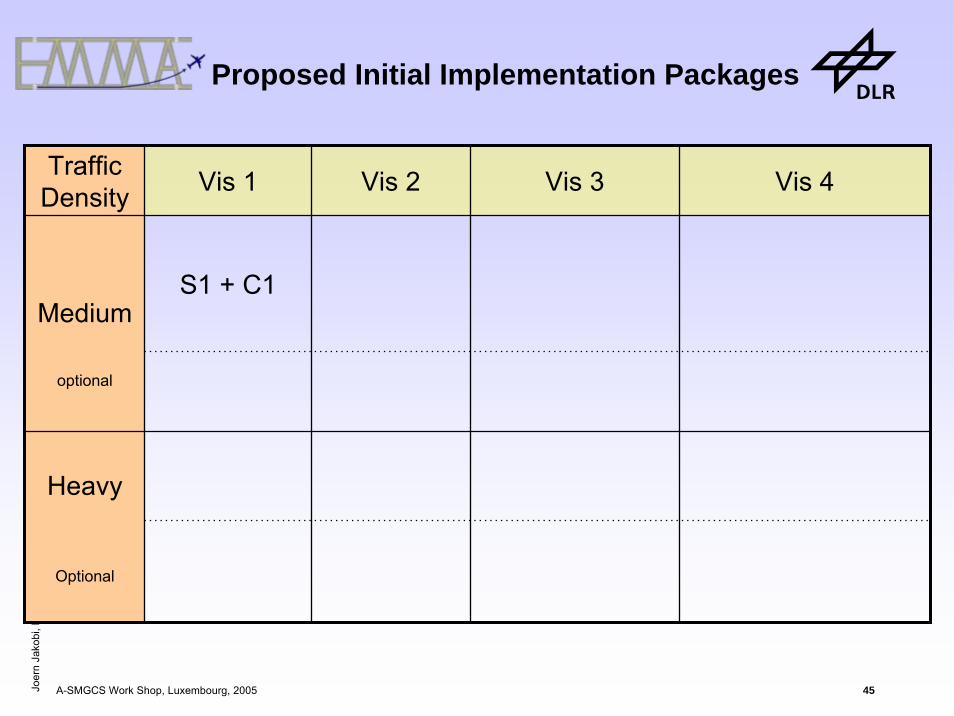
Traffic Density Vis 1 Vis 2 Vis 3 Vis 4
S1 + C1
Heavy
Optional
Medium
optional
Proposed Initial Implementation Packages

Joer
n Ja
kobi
, DLR
A-SMGCS Work Shop, Luxembourg, 2005 46
Traffic Density Vis 1 Vis 2 Vis 3 Vis 4
S1 + C1 S2 + C1
Heavy
Optional
Medium
optional
Proposed Initial Implementation Packages

Joer
n Ja
kobi
, DLR
A-SMGCS Work Shop, Luxembourg, 2005 47
Traffic Density Vis 1 Vis 2 Vis 3 Vis 4
S1 + C1 S2 + C1S2 + C1 + A2 + V2
Heavy
Optional
Medium
optional
Proposed Initial Implementation Packages
Joer
n Ja
kobi
, DLR
A-SMGCS Work Shop, Luxembourg, 2005 48

Joer
n Ja
kobi
, DLR
A-SMGCS Work Shop, Luxembourg, 2005 49
Traffic Density Vis 1 Vis 2 Vis 3 Vis 4
S1 + C1 S2 + C1S2 + C1 + A2 + V2
S3 + C4 + R3
Heavy
Optional
Medium
optional
Proposed Initial Implementation Packages

Joer
n Ja
kobi
, DLR
A-SMGCS Work Shop, Luxembourg, 2005 50
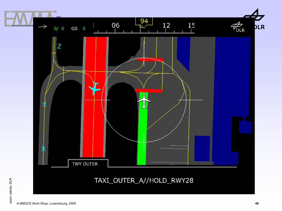
Seperation in Vis 3
Today
BWA 124531 A340
DLH 135431 B737

Joer
n Ja
kobi
, DLR
A-SMGCS Work Shop, Luxembourg, 2005 51
A 257AT72
BWA 124531 A340
DLH 135431 B737
Seperation in Vis 3
Today with A-SMGCS

Joer
n Ja
kobi
, DLR
A-SMGCS Work Shop, Luxembourg, 2005 52
A 257AT72
BWA 124531 A340
DLH 135431 B737
Seperation in Vis 3
- „Ground STCA“ or- Aircraft approaching stationary traffic (ICAO doc 9830, §3.4.5.7 b) 2))

Joer
n Ja
kobi
, DLR
A-SMGCS Work Shop, Luxembourg, 2005 53
Seperation in Vis 3
CSA 25731 AT72
DLH 135431 B737
BWA 124531 A340

Joer
n Ja
kobi
, DLR
A-SMGCS Work Shop, Luxembourg, 2005 54
Seperation in Vis 3
BWA 124531 A340
CSA 25731 AT72
DLH 135431 B737

Joer
n Ja
kobi
, DLR
A-SMGCS Work Shop, Luxembourg, 2005 55
Seperation in Vis 3
BWA 124531 A340
CSA 25731 AT72
DLH 135431 B737

Joer
n Ja
kobi
, DLR
A-SMGCS Work Shop, Luxembourg, 2005 56
Traffic Density Vis 1 Vis 2 Vis 3 Vis 4
S1 + C1 S2 + C1S2 + C1 + A2 + V2
S3 + C4 + R3
Heavy
Optional
Medium
optional
Proposed Initial Implementation Packages

Joer
n Ja
kobi
, DLR
A-SMGCS Work Shop, Luxembourg, 2005 57
Traffic Density Vis 1 Vis 2 Vis 3 Vis 4
S1 + C1 S2 + C1S2 + C1 + A2 + V2
S3 + C4 + R3S2 + C4+ V2+ R3
Heavy
Optional
Medium
optional
Proposed Initial Implementation Packages

Joer
n Ja
kobi
, DLR
A-SMGCS Work Shop, Luxembourg, 2005 58
Traffic Density Vis 1 Vis 2 Vis 3 Vis 4
S1 + C1 S2 + C1 S2 + C4+ V2+ R3 S2 + C2 + A3 + V2
Heavy
Optional
Medium
optional
Proposed Initial Implementation Packages

Joer
n Ja
kobi
, DLR
A-SMGCS Work Shop, Luxembourg, 2005 59
Traffic Density Vis 1 Vis 2 Vis 3 Vis 4
S1 + C1 S2 + C1 S2 + C4+ V2+ R3 S2 + C2 + A3 + V2
A1 + V1R3/R4 +A2 +V1
A2 + V2C2+R3/R4+A2+V1
R4 + A2 C4 + A4 + R3/R4
Heavy
Optional
Medium
optional
Proposed Initial Implementation Packages

Joer
n Ja
kobi
, DLR
A-SMGCS Work Shop, Luxembourg, 2005 60
Traffic Density Vis 1 Vis 2 Vis 3 Vis 4
S1 + C1 S2 + C1 S2 + C4+ V2+ R3 S2 + C2 + A3 + V2
A1 + V1R3/R4 +A2 +V1
A2 + V2 C2+R3/R4+A2+V1 R4 + A2 C4 + A4 + R3/R4
S2 + C3 + R4 S2 + C3 + R4 S2 + C4 + V2 + R4 S2 + C3 + A3 + V2 + R4Heavy
Optional
Medium
optional
Proposed Initial Implementation Packages

Joer
n Ja
kobi
, DLR
A-SMGCS Work Shop, Luxembourg, 2005 61
Traffic Density Vis 1 Vis 2 Vis 3 Vis 4
S1 + C1 S2 + C1 S2 + C4+ V2+ R3 S2 + C2 + A3 + V2
A1 + V1R3/R4 +A2 +V1
A2 + V2C2+R3/R4+A2+V1
R4 + A2 C4 + A4 + R3/R4
A2 + V2 A2 + V2 A2 + V3 A4 + V3
S2 + C3 + R4 S2 + C3 + R4 S2 + C4 + V2 + R4 S2 + C3 + A3 + V2 + R4Heavy
Optional
Medium
optional
Proposed Initial Implementation Packages

Joer
n Ja
kobi
, DLR
A-SMGCS Work Shop, Luxembourg, 2005 62
Traffic Density Vis 1 Vis 2 Vis 3 Vis 4
S1 + C1 S2 + C1 S2 + C4+ V2+ R3 S2 + C2 + A3 + V2
A1 + V1R3/R4 +A2 +V1
A2 + V2C2+R3/R4+A2+V1
R4 + A2 C4 + A4 + R3/R4
A2 + V2 A2 + V2 A2 + V3 A4 + V3
S2 + C3 + R4 S2 + C3 + R4 S2 + C4 + V2 + R4 S2 + C3 + A3 + V2 + R4Heavy
Optional
Medium
optional
Eurocontrol EMMA
Proposed Initial Implementation Packages

Joer
n Ja
kobi
, DLR
A-SMGCS Work Shop, Luxembourg, 2005 63
Questions…?
What did he say…?
www.dlr.de/[email protected]