electronics technology and robotics iii structure and
TRANSCRIPT
1
Electronics Technology and Robotics III Structure and Materials 1
(Notes primarily from “Underwater Robotics – Science Design and Fabrication”, an excellent book for the design, fabrication, and operation of Remotely Operated Vehicles ROVs)
Administration:
o Prayer General Introduction:
o The frame of an underwater vehicle provides a firm platform for the fixing of the necessary mechanical, electrical, and propulsion components including special tooling such as sonar, cameras, lighting, manipulators, scientific sensor and sampling equipment. ROV frames have been made by lots of different materials from plastic composites to aluminum tubing.
o In general, the materials used are chosen to give the maximum strength with the minimum weight, since weight has to be offset with buoyancy.
o The size of the frame is dependent on the following criteria. Weight of the complete ROV unit in air Volume of the onboard equipment Volume of the Sensors and Tooling Volume of the Buoyancy Load bearing criteria of the frame
Systems Interaction: o Interactivity between ROV systems causes difficulties in the design and
fabrication process. o Changing any of the power, navigation, propulsion, ballast, payload,
structure, control or tether systems affects the design and construction of the other systems.
o For instance, a team may find that they have to add another payload tool to their ROV. The frame now must be changed to accommodate the new tool which in turn affects the ballast system and possibly several other subsystems.

2
Three Basic Structure Components of an Underwater Vehicle: o There are three components in an underwater vehicle’s structure, the
frame, pressure canisters, and the fairing:
Figure 1: Three Basic Components of an Underwater Vehicle
Frame – the internal supporting structure that gives a vehicle its shape
It is required to support the weight of the vehicle in and out of the water.
It has to distribute concentrated forces such as lifting points. It must resist hydrodynamic forces from currents, waves, and
thruster propulsion. All of the other ROV components such as cameras, pressure
canisters, and thrusters must be mounted such a way that servicing is convenient.
It must withstand the forces from the onboard tools themselves and the additional forces transferred to the frame while the tools are in operation.
The frame should guard the underwater vehicle from collisions underwater and rough treatment out of water.
It should protect the tether from damage. Pressure Canisters – rigid, watertight containers that protect
contents from water and pressure They have to withstand water pressure forces. They must keep the integrity of the watertight seals. They need to provide a way to service their contents. They may include wire penetrations in their outer walls and
still maintain water tightness. They must provide a way for mounting to the frame.
Fairing – the external surface of a vehicle, such as a submarine, that serves to reduce drag
Fairing should minimize the drag the vehicle encounters in the water.
It should have a smooth surface so the vehicle does not get caught or entangled in its working environment.
o ROVs are normally made without a fairing since they do not travel great distances nor at high speeds.

3
Structure Basics: o Strength and Stiffness:
Strength – the power to resist strain or stress without experiencing damage; durability
Stiffness – the measure of the resistance offered by a body to deformation.
Figure 2: ROV Frame Under Three Basic Structural Forces
The strength and stiffness of your ROV is subject to: The strength and stiffness of the individual parts The geometry of the structural members in the vehicle How the parts are fastened to each other Perform Structures and Materials Lab 1 – Strength and
Stiffness of Geometric Configurations o Weight – the force that gravitation exerts upon a body
Although buoyancy can be added to compensate for more weight under water, the additional weight encumbers the handling of the vehicle while out of water.
In general, less weight is superior than more weight. Factors to consider when putting your underwater vehicle on a
“diet”: Limit the size of your vehicle Use materials that have higher strength and stiffness for
their density Make use of material cross-sections that lend themselves to
higher strength and stiffness o Construction and Maintenance:
Keep it simple; simple designs are easier to construct and have fewer things that can malfunction. One of the MATE competition score sheets lists “Components easy to access for maintenance & troubleshooting” as one of their line items.
COTS parts – Commercial Off-The-Shelf parts: Parts that are ready-made and commercially available. The final part is normally quicker to purchase than to build
the part yourself.

4
COTS parts are more reliable and occasionally cheaper than DIY parts.
DIY parts – Do-It-Yourself parts: More educational Have a backup part available that can be easily inserted
In the MATE competitions, multiple commercial components such as tethers or thrusters are encouraged. Systems designed to perform multiple, complex functions from one “black box” or series of components designed to integrate with each other are discouraged. An example is the FIRST controller system.
o Safety: Safety by design Safety is always the first priority in the design and operation of an
underwater vehicle. The standards for manned vehicles are understandably much higher and more rigid than an unmanned vehicle.
Partial list of potential hazards for unmanned vehicles: Injury from rollover or shifting during transportation Electrical shock Discharge from stored energy such as hydraulics and
pneumatics Lacerations from sharp objects Hazards to divers nearby Injuries during the fabrication process
Safety by design is a concept that supports the view that along with quality and cost; safety is determined during the design stage. This proactive approach results in a decrease in accidents and injuries.
Code of Practice for the Safe and Efficient Operation of Remotely Operated Vehicles by IMCA: http://www.imca-int.com/documents/divisions/rov/docs/IMCAR004.pdf
2011 MATE safety inspection sheet: See Appendix A or link to http://www.materover.org/rov_competition_files/2011/2011_SafetyInspection.pdf
5
Structural Cross Sections and Geometric Configurations: o The goal when designing an underwater vehicle frame is to maximize the
strength and stiffness with the minimum weight and material. o Connecting and joining the frame elements is a key factor in your material
selection. o Structural Cross Sections:
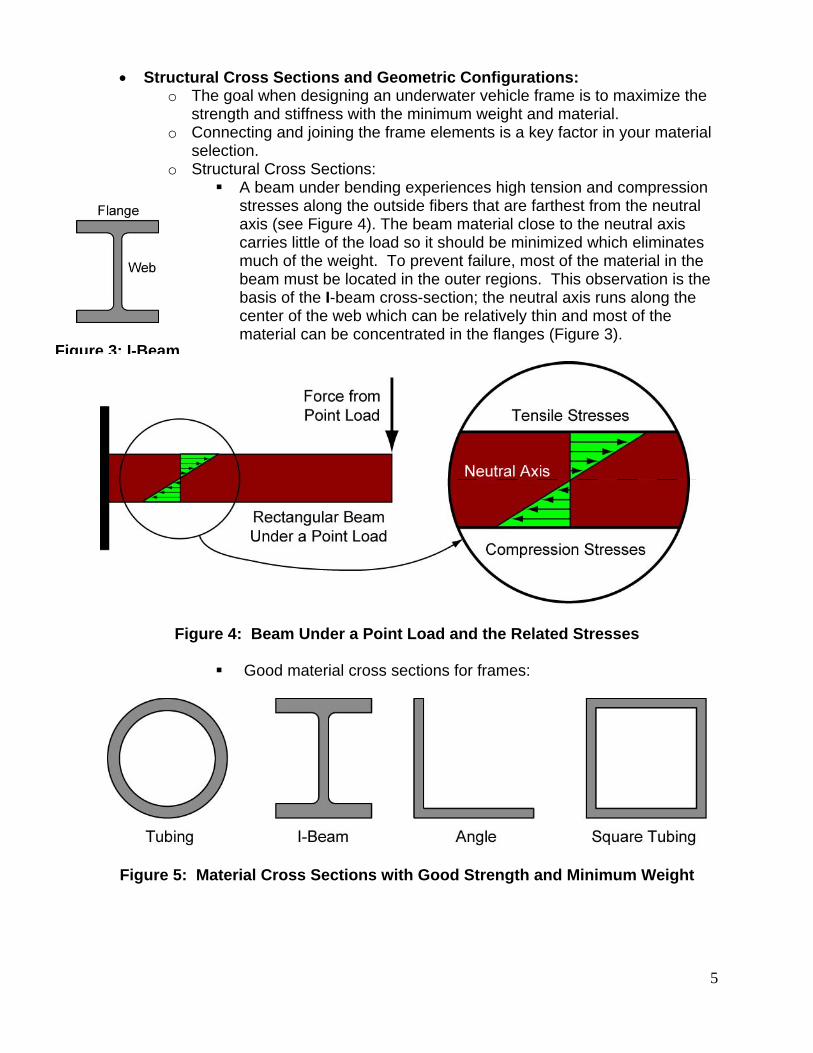
A beam under bending experiences high tension and compression stresses along the outside fibers that are farthest from the neutral axis (see Figure 4). The beam material close to the neutral axis carries little of the load so it should be minimized which eliminates much of the weight. To prevent failure, most of the material in the beam must be located in the outer regions. This observation is the basis of the I-beam cross-section; the neutral axis runs along the center of the web which can be relatively thin and most of the material can be concentrated in the flanges (Figure 3).
Figure 4: Beam Under a Point Load and the Related Stresses
Good material cross sections for frames:
Figure 5: Material Cross Sections with Good Strength and Minimum Weight
Figure 3: I-Beam
6
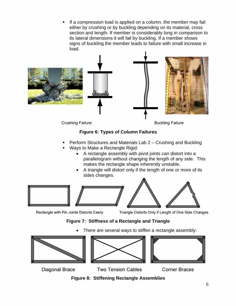
If a compression load is applied on a column, the member may fail either by crushing or by buckling depending on its material, cross section and length. If member is considerably long in comparison to its lateral dimensions it will fail by buckling. If a member shows signs of buckling the member leads to failure with small increase in load.
Figure 6: Types of Column Failures
Perform Structures and Materials Lab 2 – Crushing and Buckling Ways to Make a Rectangle Rigid:
A rectangle assembly with pivot joints can distort into a parallelogram without changing the length of any side. This makes the rectangle shape inherently unstable.
A triangle will distort only if the length of one or more of its sides changes.
Figure 7: Stiffness of a Rectangle and Triangle
There are several ways to stiffen a rectangle assembly:
Figure 8: Stiffening Rectangle Assemblies

7
Cornerstone Electronics Technology and Robotics III Structures and Materials Lab 1 – Strength and Stiffness of Geometric
Configurations
Purpose: The student tests several structural geometric configurations under load to determine the relative load bearing capacity of each configuration.
Apparatus and Materials: o 5 – Popsicle Sticks o 6 – #6x32x3/4” Machine Screws o 6 – #6x32 Nuts
Procedure: o Drill the ends of the Popsicle sticks with a #25 drill bit (creates a loose fit
for a #6x32 screw). o Connect the ends of 3 Popsicle sticks to form a triangle using the machine
screws and nuts. Do not tighten the machine screws and nuts, but only tighten until they barely touch the wood. See the illustration below.
o Apply a force with your finger as shown above and note the stability and the load capacity of the shape.
o Now construct the Popsicles sticks into the configurations of squares and pentagons. Tighten the screws as before.
8
o Again apply force with your finger(s) as shown above and note the stability and the load capacity of the each shape.
o Record your results.
Results: o Evaluate the load capacity of each geometric configuration. Make a list
from weakest to the strongest geometric configuration.
________________________
________________________
________________________
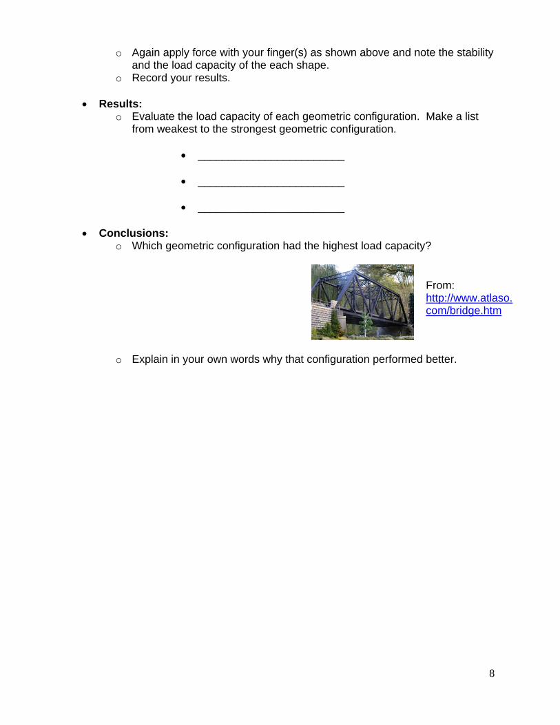
Conclusions: o Which geometric configuration had the highest load capacity?
o Explain in your own words why that configuration performed better.
From: http://www.atlaso.com/bridge.htm

9
Purpose: The student tests the effect that a material cross section has on strength and stiffness.
Apparatus and Materials:
o 1 – 10-Ton Hydraulic Bench Press with Pressure Gauge (http://www.northerntool.com/shop/tools/product_200332763_200332763?cm_ite=145208&cm_pla=Metal%20Fabrication%3EShop%20Presses&cm_cat=Shopping&cm_ven=Aggregates)
o 1 - 0.75” OD x 0.62” ID x 12” Aluminum Tubing – From McMaster Carr: http://www.mcmaster.com/#9056k713/=d99sia
o 1 – 0.5” x 72” Aluminum Rod – From McMaster Carr: http://www.mcmaster.com/#8974k33/=d99uph
o 1 – ¾” x 5’ PVC Rod – From McMaster Carr: http://www.mcmaster.com/#pvc-rods/=d9fti4
o Nylon Strap and Hose Clamps
Procedure: o READ, UNDERSTAND, AND APPLY ALL SAFETY INSTRUCTIONS
FOR THE HYDRAULIC BENCH PRESS BEFORE USE. o PVC – Crushing and Buckling:
Cut 2.5 cm and 30 cm pieces off the PVC rod. Mill both ends of the rods to form a smooth surface that is
perpendicular to the rod length. Secure the nylon strap with hose clamps onto all 30 cm pieces used in
this lab. Anchor the other end of the strap to a fixed surface. Load the hydraulic bench press with each piece such that the
compression force is applied along the length of the rod. Measure the maximum force each can withstand and record your
results. o Aluminum – Cross Sections:
Lathe turn down the entire length of a 30 cm+ rod to a diameter of 10.7 mm.
Cut a 30 cm pieces off the 10.7 mm diameter aluminum rod. Mill all of the ends of the tubing and rod. Secure the rod with straps. Load the hydraulic bench press with the ¾” aluminum tubing. Increase the press load until the maximum compression force is
reached. Record the maximum force. Repeat the compression test using the 10.7 mm diameter
aluminum rod. Record your results. Results:
o PVC:

10
o Aluminum:
Conclusions: o PVC:
Which length of PVC exhibited crushing failure?
Which length of PVC exhibited buckling failure?
The compression strength of PVC pipe is approximately 9,600 psi.
The area of the ¾” PVC rod is 0.442 in2. How do your test results compare to the maximum calculated value?
o Aluminum: Fill in the table below.
For experimental purposes, are the two areas equal?
Which shape can carry more compression load?
What does that say about the cross section of the shape that carries the higher load?
11
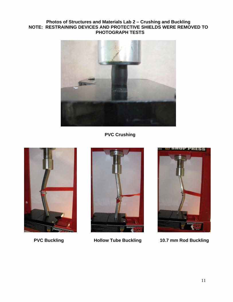
Photos of Structures and Materials Lab 2 – Crushing and Buckling NOTE: RESTRAINING DEVICES AND PROTECTIVE SHIELDS WERE REMOVED TO
PHOTOGRAPH TESTS
PVC Crushing
PVC Buckling Hollow Tube Buckling 10.7 mm Rod Buckling

12
Appendix A