electronically reconfigurable reflective phase shifter...
TRANSCRIPT
Electronically Reconfigurable Reflective Phase Shifter for Circularly Polarized Reflectarray Systems
P. Padilla, J. F. Valenzuela-Valdés, J. L. Padilla, J. M. Fernández-González, and M. Sierra-Castaner
Abstract—This letter presents the design of a two-port electronically reconfigurable phase shifter for circularly polarized reflectarray systems at microwave frequencies. The phase shifter is based on 3 dB/90° couplers combined with reflective circuits that introduce sequentially the phase variation. Each reflective circuit, formed by printed elements (L) and tunable varactors, produces the phase variation due to the variable capacity value of the varactor. The phase shifting process includes three different stages of phase shifting for the signal in its way from the input port towards the output port through the phase shifter. Both ports are interchangeable, acting either as input or output ports. This fulfils the reflection requirements of circularly polarized reflectarrays, being especially suitable for this purpose. The complete design, together with its circuital behavior and performance results, are depicted in this document.
Index Terms—Ku band, microwave phase shifters, reflectarrays, 3 dB/90° coupler.
I. INTRODUCTION
IN THE last years, planar multi-layered antennas have become an excellent option for the design of radiating el
ements and array antennas due to their easy manufacturing, low profile and reduced costs [1], [2]. In particular, in the case of reflectors, they are been replaced by planar structures called reflectarrays. Reflectarray antennas have become a real alternative in transmission/reception systems whose requirements impose severe constraints in terms of radiation pattern, directivity or gain [3]. The underlying idea in reflectarrays is the substitution of the conventional conformed reflector: the reflective surface that transforms in a plane wave the wave coming from the feeder is replaced by a planar array of radiating elements with an adequate phase distribution at each array cell [3], [4]. The phase shifting strategy, which depends on the system topology and the final antenna specifications, is usually provided by either a reflective delay line circuit connected to
rA(in/out)
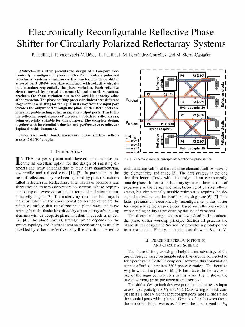
Fig. 1. Schematic working principle of the reflective phase shifter.
each radiating cell or at the radiating element itself by varying the element size and shape [5]. The first strategy is the one that this letter affords with the design of an electronically tunable phase shifter for reflectarray systems. There is a lot of experience in the design and manufacturing of passive reflectarrays, but electronically tunable reflectarray requires the design of active devices, that is still an ongoing issue [6], [7]. This letter presents an electronically reconfigurable phase shifter for circularly reflectarray devices, based on reflective circuits whose tuning ability is provided by the use of varactors.
This document is organized as follows: Section II introduces the phase shifter working principle. Section III presents the phase shifter design and Section IV provides a prototype and its measurements. Finally, conclusions are drawn in Section V.
II. PHASE SHIFTER FUNCTIONING
AND CIRCUITAL SCHEME
The phase shifting working principle takes advantage of the use of designs based on tunable reflective circuits connected to four-port hybrid 3 dB/90° couplers. However, this combination cannot afford a complete 360° phase variation. The iterative way in which the phase shifting is introduced in the device is one of the main contributions in this work. Fig. 1 shows the design working principle hereinafter described.
The shifter design includes two ports that act either as input or as output ports (ports PA and PB ). Considering for each coupler that PI and P4 are the input/output ports, and P2 and P3 are the coupled ports with a phase difference of 90° between them, the proposed design works as follows: the input signal in PA
varactor (C) printed L hybrid coupler substrate
reflective circuit
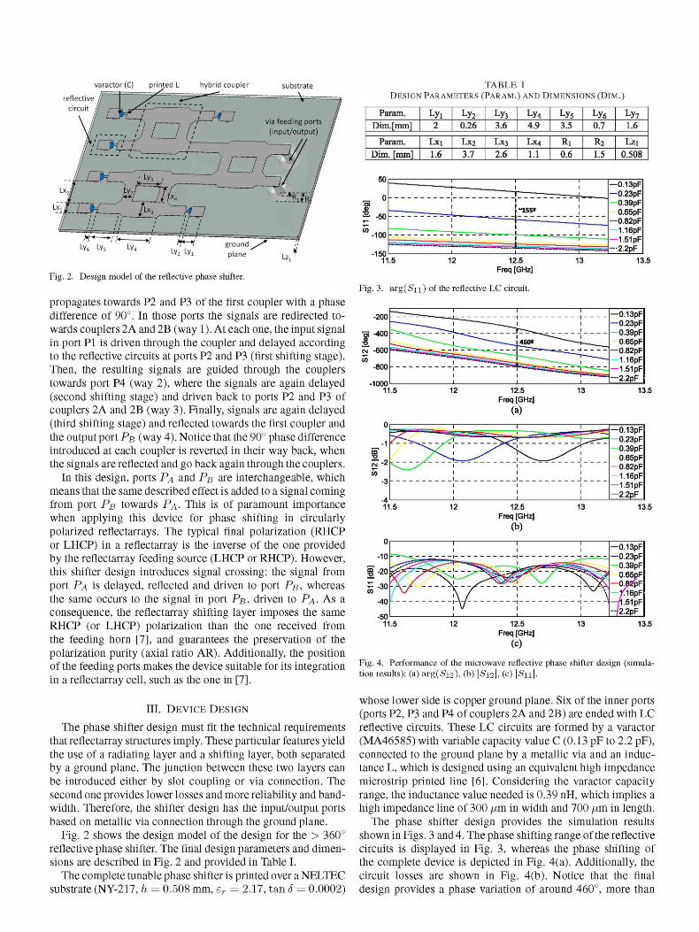
TABLE I D E S I G N P A R A M E T E R S ( P A R A M . ) A N D D I M E N S I O N S ( D I M . )
Ly* Ly^ ^ Ly2 LVl
Fig. 2. Design model of the reflective phase shifter.
propagates towards P2 and P3 of the first coupler with a phase difference of 90°. In those ports the signals are redirected towards couplers 2A and 2B (way 1). At each one, the input signal in port PI is driven through the coupler and delayed according to the reflective circuits at ports P2 and P3 (first shifting stage). Then, the resulting signals are guided through the couplers towards port P4 (way 2), where the signals are again delayed (second shifting stage) and driven back to ports P2 and P3 of couplers 2A and 2B (way 3). Finally, signals are again delayed (third shifting stage) and reflected towards the first coupler and the output port PB (way 4). Notice that the 90° phase difference introduced at each coupler is reverted in their way back, when the signals are reflected and go back again through the couplers.
In this design, ports PA and PB are interchangeable, which means that the same described effect is added to a signal coming from port PB towards PA- This is of paramount importance when applying this device for phase shifting in circularly polarized reflectarrays. The typical final polarization (RHCP or LHCP) in a reflectarray is the inverse of the one provided by the reflectarray feeding source (LHCP or RHCP). However, this shifter design introduces signal crossing: the signal from port PA is delayed, reflected and driven to port PB, whereas the same occurs to the signal in port PB, driven to PA- AS a consequence, the reflectarray shifting layer imposes the same RHCP (or LHCP) polarization than the one received from the feeding horn [7], and guarantees the preservation of the polarization purity (axial ratio AR). Additionally, the position of the feeding ports makes the device suitable for its integration in a reflectarray cell, such as the one in [7].
III. DEVICE DESIGN
The phase shifter design must fit the technical requirements that reflectarray structures imply. These particular features yield the use of a radiating layer and a shifting layer, both separated by a ground plane. The junction between these two layers can be introduced either by slot coupling or via connection. The second one provides lower losses and more reliability and bandwidth. Therefore, the shifter design has the input/output ports based on metallic via connection through the ground plane.
Fig. 2 shows the design model of the design for the > 360° reflective phase shifter. The final design parameters and dimensions are described in Fig. 2 and provided in Table I.
The complete tunable phase shifter is printed over a NELTEC substrate (NY-217, h = 0.508 mm, er = 2.17, tan S = 0.0002)
Param.
Dim. [mm] Lyi 2
Ly2
0.26
Ly3
3.6 Ly4
4.9 Ly5
3.5 Ly6
0.7 Ly7
1.6
Param.
Dim. [mm]
Lxi 1.6
LX2
3.7 Lx3 2.6
LX4
1.1 Ri 0.6
R2
1.5 Lzi
0.508
—0.13pF —0.23pF —0.39pF
0.65pF —0.82pF
1.16pF — 1.51pF —2.2pF
13.5
Fig. 3. a r g ( S i i ) of the reflective LC circuit.
-1000
—0.13pF —0.23pF
0.39pF 0.65pF
—0.82pF 1.16pF
— 1.51pF| —2.2pF
13.5
-0.13pF -0.23pF -0.39pF -0.65pF -0.82pF -1.16pF -1.51pF -2.2pF
12.5 Freq [GHz]
(b)
13.5
13.5
Fig. 4. Performance of the microwave reflective phase shifter design (simulation results): (a) arg(S12), (b) \S12\, (c) | S i i | .
whose lower side is copper ground plane. Six of the inner ports (ports P2, P3 and P4 of couplers 2A and 2B) are ended with LC reflective circuits. These LC circuits are formed by a varactor (MA46585) with variable capacity value C (0.13 pF to 2.2 pF), connected to the ground plane by a metallic via and an inductance L, which is designed using an equivalent high impedance microstrip printed line [6]. Considering the varactor capacity range, the inductance value needed is 0.39 nH, which implies a high impedance line of 300 /im in width and 700 /im in length.
The phase shifter design provides the simulation results shown in Figs. 3 and 4. The phase shifting range of the reflective circuits is displayed in Fig. 3, whereas the phase shifting of the complete device is depicted in Fig. 4(a). Additionally, the circuit losses are shown in Fig. 4(b). Notice that the final design provides a phase variation of around 460°, more than
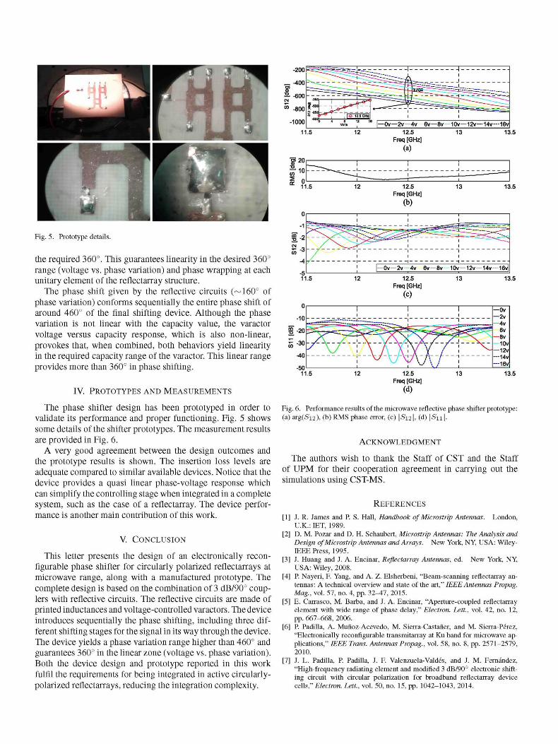
Fig. 5. Prototype details.
the required 360°. This guarantees linearity in the desired 360° range (voltage vs. phase variation) and phase wrapping at each unitary element of the reflectarray structure.
The phase shift given by the reflective circuits (^160° of phase variation) conforms sequentially the entire phase shift of around 460° of the final shifting device. Although the phase variation is not linear with the capacity value, the varactor voltage versus capacity response, which is also non-linear, provokes that, when combined, both behaviors yield linearity in the required capacity range of the varactor. This linear range provides more than 360° in phase shifting.
IV. PROTOTYPES AND MEASUREMENTS
The phase shifter design has been prototyped in order to validate its performance and proper functioning. Fig. 5 shows some details of the shifter prototypes. The measurement results are provided in Fig. 6.
A very good agreement between the design outcomes and the prototype results is shown. The insertion loss levels are adequate compared to similar available devices. Notice that the device provides a quasi linear phase-voltage response which can simplify the controlling stage when integrated in a complete system, such as the case of a reflectarray. The device performance is another main contribution of this work.
V. CONCLUSION
This letter presents the design of an electronically recon-flgurable phase shifter for circularly polarized reflectarrays at microwave range, along with a manufactured prototype. The complete design is based on the combination of 3 dB/90° couplers with reflective circuits. The reflective circuits are made of printed inductances and voltage-controlled varactors. The device introduces sequentially the phase shifting, including three different shifting stages for the signal in its way through the device. The device yields a phase variation range higher than 460° and guarantees 360° in the linear zone (voltage vs. phase variation). Both the device design and prototype reported in this work fulfil the requirements for being integrated in active circularly-polarized reflectarrays, reducing the integration complexity.
4 vwt 1,2 " |—Ov—2v 4v 6v—8v 10v— 12v— 14v—1~6v 11.5 12 12.5 13 13.5
Freq [GHz]
(a)
$20C- ! ! ! 1
^ 11.5 12 12.5 13 13.5 Freq [GHz]
|—Ov—2v 4v 6v—8v 10v— 12v— 14v—16v|
11.5 12 12.5 13 13.5 Freq [GHz]
(C)
•10 - - - -----------ri-.- ! ! _ 2 v
-SU' ' ' " ' ' • 11.5 12 12.5 13 13.5
Freq [GHz] (d)
Fig. 6. Performance results of the microwave reflective phase shifter prototype: (a) arg(Si2), (b) RMS phase error, (c) \S12\, (d) \Su\.
ACKNOWLEDGMENT
The authors wish to thank the Staff of CST and the Staff of UPM for their cooperation agreement in carrying out the simulations using CST-MS.
REFERENCES
[1] J. R. James and P. S. Hall, Handbook of Microstrip Antennas. London, U.K.: IET, 1989.
[2] D. M. Pozar and D. H. Schaubert, Microstrip Antennas: The Analysis and Design of Microstrip Antennas and Arrays. New York, NY, USA: Wiley-IEEE Press, 1995.
[3] J. Huang and J. A. Encinar, Reflectarray Antennas, ed. New York, NY, USA: Wiley, 2008.
[4] P. Nayeri, F. Yang, and A. Z. Elsherbeni, "Beam-scanning reflectarray antennas: A technical overview and state of the art," IEEE Antennas Propag. Mag, vol. 57, no. 4, pp. 32-47, 2015.
[5] E. Carrasco, M. Barba, and J. A. Encinar, "Aperture-coupled reflectarray element with wide range of phase delay," Electron. Lett., vol. 42, no. 12, pp. 667-668, 2006.
[6] P. Padilla, A. Muñoz-Acevedo, M. Sierra-Castaner, and M. Sierra-Pérez, "Electronically reconfigurable transmitarray at Ku band for microwave applications," IEEE Trans. Antennas Propag., vol. 58, no. 8, pp. 2571-2579, 2010.
[7] J. L. Padilla, P. Padilla, J. F. Valenzuela-Valdés, and J. M. Fernández, "High-frequency radiating element and modified 3 dB/90° electronic shifting circuit with circular polarization for broadband reflectarray device cells," Electron. Lett., vol. 50, no. 15, pp. 1042-1043, 2014.