a novel tee network based six bit digital phase shifter...
TRANSCRIPT
International Journal of Electrical, Electronics and Data Communication, ISSN: 2320-2084 Volume- 1, Issue- 7, Sep-2013
A Novel Tee Network Based Six Bit Digital Phase Shifter For St Radar
75
A NOVEL TEE NETWORK BASED SIX BIT DIGITAL PHASE SHIFTER FOR ST RADAR
1DEEPA JAGYASI, 2K. P. RAY, 3SUSHAMA CHOUDHARI, 4SHOBA KRISHNAN
1VESIT, Mumbai University, Mumbai, 2SAMEER, IIT Bombay, Powai, Mumbai Email: [email protected], [email protected], [email protected]
Abstract— The evolution of phased-array technology to its present sophisticated form is strongly based on the development of electronically variable phase shifters. In this paper, Six bit digital phase shifter for transmit-receive (TR) module associated with each antenna in a circular array of 576 Yagi-Uda antennas for the Stratospheric Tropospheric (ST) Radar has been designed using Tee networks. It is designed to achieve the beamsteering capability of 360° azimuthal and ±15° elevation. The proposed design had been mathematically modeled, and further verified computationally in MATLAB. This complete design has been simulated in Advanced Design System (ADS) software using the synthesized lumped component values. The phase shifter has been designed to work at the operating frequency of 212MHz and the results for phase shifts, phase error, insertion loss, return loss for the designed phase shifter has been obtained for all the 64 control signals over a range of frequency. Keywords— Phase Shifter, ST Radar, Tee Network, Transmit Receive (TR) Module. I. INTRODUCTION Phase shifters are mainly applied to telecommunications, radar, control and measurement systems. Radar systems make use of multi-bit digital phase shifters to form transmitting-receiving characteristics of antenna systems [1]. Digital phase shifter provides the discrete change in phase i.e. 22.5°, 45°, 90°, 180° and can be controlled by digital control inputs. A phase shifter is classified as a two-port device whose basic function is to provide a change in phase of RF signal with minimal attenuation. Several popular types of phase shifters like reflective, transmission, switched line and switched network, are found to be implemented and used depending upon their functionality [2], [3], [4], [5], [6]. Here we present the development of Six Bit digital phase shifter which is designed using the blocks of Tee network lumped elements. It is proposed to be implemented in the transmit-receive module associated with each antenna in circular array of 576 Yagi-Uda antennas in the Stratospheric Tropospheric (ST) Radar project, designed and developed by Society for Applied Microwave Electronics Engineering and Research (SAMEER), Department of Electronics and Information Technology (DeitY) Powai, Mumbai for the Gauhati University, Aasam. It is realized to achieve the beamsteering capability with elevation angle of ±15° and 360° azimuthal angle. The designed phase shifter works on the six bit digital control logic to achieve the phase shift of 0° to 360° and offers the minimum resolution of 5.625°. From literature [1], we know the length of a transmission line can shift the phase of an input RF signal which depends on the frequency of the signal and desired amount of phase shift. It was mathematically found that the length of transmission line required was quite
large at the operating frequency of 212 MHz and required length goes in increasing to achieve larger phase shifts. 17.675 cm of transmission line is required to obtain phase shift of 45° at 212 MHz which ultimately increases the size of complete design. The key contribution of this paper is the development of six bit digital phase shifter designed using Tee network blocks which are synthesized as an equivalent to a piece of transmission line. A Tee network can thus replace the large transmission line and offers desired change in phase. The phase shifter design has been discussed in the Section II. In Section III we develop the mathematical design along with the reverse synthesis of the proposed six bit digital phase shifter. The design was verified by performing simulations in Advanced Design System (ADS) tool and the simulation results obtained are presented in Section IV. The implementation of the complete phase shifter design is discussed in Section V. Section VI illustrates the results obtained in terms of phase error, losses namely insertion loss and return loss and phase shifts for all the input control signals. Section VII we conclude the paper. II. PHASE SHIFTER DESIGN Six bit digital phase shifter consists of a number of cascaded units, each provides one-bit change in the input RF signal to functions in accordance with the six bit digital control input. The basic building blocks for proposed design is illustrated in Fig 1. It consists of six different cascaded units that provide the phase shift of 5.625°, 11.26°, 22.5°, 45°, 90°, 180°, respectively as shown in Fig.1. In order to achieve a desired beam positioning in ST Radar, the Radar controller generates the digital control input for all the array elements. This six bit digital input is fed to

International Journal of Electrical, Electronics and Data Communication, ISSN: 2320-2084 Volume- 1, Issue- 7, Sep-2013
A Novel Tee Network Based Six Bit Digital Phase Shifter For St Radar
76
TR module, according to which the phase shifter functions.
Fig.1 Basic Building Blocks of six bit digital phase shifter
design. Based on the active inputs (logic 1) the corresponding block shifts the signal and adds to the overall required phase shift. As the control signal is six bit digital in nature, 64 phase states exists with the phase shift of 5.625° between any two successive states. All the blocks have been synthesized as the Tee networks. The synthesis had been carried out by assuming the Tee network to be equivalent to a piece of transmission line that provides the desired phase shift, designed to function at 212MHz of frequency. III. MATHEMATICAL MODELLING OF
PHASE SHIFTER The design for the phase shifter has been mathematically developed and the synthesis for a Tee network is presented in this section.
Fig.2 Tee network equivalent of transmission line.
REVERSE SYNTHESIS In reverse synthesis the synthesized values of lumped components in Tee network are used to compute the S parameter (refer fig.3)
Fig.3 Tee network
The Z parameters for the above network can be computed easily by applying KVL which results into,

International Journal of Electrical, Electronics and Data Communication, ISSN: 2320-2084 Volume- 1, Issue- 7, Sep-2013
A Novel Tee Network Based Six Bit Digital Phase Shifter For St Radar
77
IV. SIMULATION RESULTS The Tee network blocks synthesized based on the mathematical modeling have been verified through simulations in ADS. Fig. 4 shows the design implementation for a lumped network, to result in the phase shift of 90 degree for the input control signal 010000, by using the lumped component values obtained from the mathematical design discussed previously.
Fig.4 Design implementation for phase shift of 90 degree in
ADS The results of this design are depicted in Fig.5. The markers M1, M2, M3 shown in Fig.5 indicates the
performance of the designed circuit at desired frequency of 212 MHz. It can be seen that the phase shift of -90.00 degree is obtained with very small insertion loss of -4.12E-06 dB and the return loss of -60.229dB.
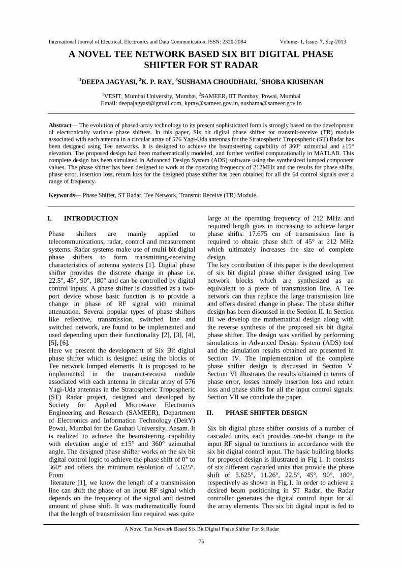
Fig.6 Design implementation for phase shift of 151.875 degree
in ADS The deign implementation for the control input 011011 to result in the phase shift of 151.875° is shown in Fig. 6. It consists of cascaded blocks designed to provide shift of and 90°, 45°, 11.25° and 5.625° and the result for this is depicted in Fig. 7. The design results in the phase shift of 151.792° with the phase error of 0.083° and the insertion loss and return loss of -2.053E-5 dB and -53.255 dB respectively.
Fig.5 Simulation Results for the design implementation for phase shift of 90 degree in ADS. (a)Phase(S(2,1)): Phase shift plot (b)dB(S(2,1)): Insertion loss plot, (c)dB(S(1,1)): Return loss
International Journal of Electrical, Electronics and Data Communication, ISSN: 2320-2084 Volume- 1, Issue- 7, Sep-2013
A Novel Tee Network Based Six Bit Digital Phase Shifter For St Radar
78
Fig.7 Simulation Results for the design implementation for phase shift of 151.875 degree in ADS. (a)Phase(S(2,1)): Phase shift plot (b)dB(S(2,1)): Insertion loss plot, (c)dB(S(1,1)): Return loss
V. IMPLEMENTATION OF TEE
NETWORK BASED SIX BIT DIGITAL PHASE SHIFTER
In this section we present the complete design of the six bit digital phase shifter which includes all six blocks along with a switching network as depicted in Fig.8. As shown all the blocks in the phase shifter are implemented using the two port tee network in order to individually provide the phase shift of 5.625, 11.25, 22.5, 45 and 90 degree. The implementation of the block that shifts the signal by 180 degree is done by the use of two tee networks blocks in cascade each with 90 degree phase shift. In order to obtain the results for all possible 64 control signals, six SPDT switches have been used. This enables the RF signal to be switched according to the six bit digital control input provided by the radar controller. Whenever the control input bit to a particular network block is high, phase of RF signal passing through that corresponding network is shifted and adds to the overall phase shift. In case of low control input bit the network is bypassed. Coupling capacitors have been used between the two successive networks to block the dc component in the RF path. The voltage divider network is added to provide supply of 2.2V to the SPDT switch IC used. Phase shifter is designed to function at the operating frequency of 212MHz, for all possible digital control signals and provides the minimum phase shift of 5.625 degree.
Fig.8. Schematic of the Tee network based six bit digital phase
shifter VI. COMPUTATIONAL RESULTS AND
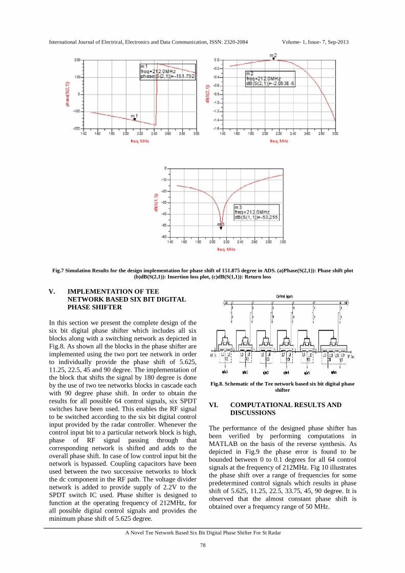
DISCUSSIONS The performance of the designed phase shifter has been verified by performing computations in MATLAB on the basis of the reverse synthesis. As depicted in Fig.9 the phase error is found to be bounded between 0 to 0.1 degrees for all 64 control signals at the frequency of 212MHz. Fig 10 illustrates the phase shift over a range of frequencies for some predetermined control signals which results in phase shift of 5.625, 11.25, 22.5, 33.75, 45, 90 degree. It is observed that the almost constant phase shift is obtained over a frequency range of 50 MHz.
International Journal of Electrical, Electronics and Data Communication, ISSN: 2320-2084 Volume- 1, Issue- 7, Sep-2013
A Novel Tee Network Based Six Bit Digital Phase Shifter For St Radar
79
Fig 9. Phase error in degree for all input control signals at
design frequency of 212MHz.
Fig.10 Phase Shift (degree) obtained over a range of
frequencies (Hz) Fig.11 and Fig.12 illustrates different curves of insertion loss and return loss respectively, for all 64 control signals over a range of frequency. The insertion loss obtained is close to zero for a range of frequency and being minimum at the design frequency. It is also observed that the return loss lower that -20dB over a wide frequency band. From the different curves of return loss in Fig. 12 it is observed that the phase shifter is properly matched at the design Frequency of 212MHz which enhances the overall performance of the design.
Fig.11 Insertion loss curves wrt Frequency (Hz) for all control
signals
Fig.12 Return loss curves wrt Frequency (Hz) for all control
signals
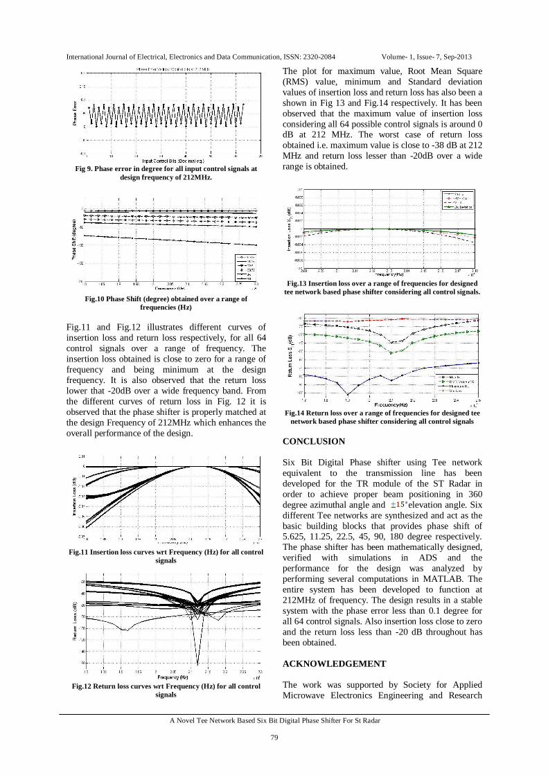
The plot for maximum value, Root Mean Square (RMS) value, minimum and Standard deviation values of insertion loss and return loss has also been a shown in Fig 13 and Fig.14 respectively. It has been observed that the maximum value of insertion loss considering all 64 possible control signals is around 0 dB at 212 MHz. The worst case of return loss obtained i.e. maximum value is close to -38 dB at 212 MHz and return loss lesser than -20dB over a wide range is obtained.
Fig.13 Insertion loss over a range of frequencies for designed
tee network based phase shifter considering all control signals.
Fig.14 Return loss over a range of frequencies for designed tee
network based phase shifter considering all control signals CONCLUSION Six Bit Digital Phase shifter using Tee network equivalent to the transmission line has been developed for the TR module of the ST Radar in order to achieve proper beam positioning in 360 degree azimuthal angle and elevation angle. Six different Tee networks are synthesized and act as the basic building blocks that provides phase shift of 5.625, 11.25, 22.5, 45, 90, 180 degree respectively. The phase shifter has been mathematically designed, verified with simulations in ADS and the performance for the design was analyzed by performing several computations in MATLAB. The entire system has been developed to function at 212MHz of frequency. The design results in a stable system with the phase error less than 0.1 degree for all 64 control signals. Also insertion loss close to zero and the return loss less than -20 dB throughout has been obtained. ACKNOWLEDGEMENT The work was supported by Society for Applied Microwave Electronics Engineering and Research

International Journal of Electrical, Electronics and Data Communication, ISSN: 2320-2084 Volume- 1, Issue- 7, Sep-2013
A Novel Tee Network Based Six Bit Digital Phase Shifter For St Radar
80
(SAMEER), Department of Electronics and Information Technology (DeitY) Powai, Mumbai. REFERENCES [1] I.J. Bahl. Lumped Elements for Rf and Microwave Circuits.
Effective Project Management Series. ARTECH HOUSE Incorporated, 2003.
[2] Tapas Mondal, Milan Mazumdar, Rowdra Ghatak and Rowdra Ghatak. Adaptive Phased Array Antenna Based on NMOS Phase Shifter for Intelligent Transport System Application. In Applied Electromagnetics Conference (AEMC), 2011 IEEE, pages 1-4, 978-1-4577-1098-8
[3] G. L. Tan, R. E.Mihailovich, J. B. Hacker, J. E DeNatale, and G. M. Rebeiz. A 4-bit miniature x-band mems phase shifter using switched-lc networks. In IEEEMTT-S International Mi-crowave Symposium Digest, pages 1477 – 1480, 2003.
[4] C.W. Suckling, P.N. Rigby, T. Bambridge, R.S. Pengelly, and R.S. Butlin. The performance of gaas lumped element phase shifters at s and c band. In 13th European Microwave Conference, pages 374 – 379, 1983.
[5] M. Kim, J.G. Yang and K. Yang. Switched transmission-line type Q-band 4-bit MMIC phase shifter using InGaAs pin diodes. In ELECTRONICS LETTERS 4th February 2010 Vol. 46 No. 3
[6] Iulian Rosu. Phase shifters, 2013. Last Accessed on June 2013 [7] D.M. Pozar. Microwave Engineering. Wiley, 2005.