electrical machines and energy conversion unit 1 deck 2 dc generator basics
TRANSCRIPT

Electrical Machines and
Energy Conversion
Unit 1 Deck 2DC Generator Basics

FIGURE 4-1 Schematic diagram of an elementary ac generator turning at 1 revolution per second.
Theodore WildiElectrical Machines, Drives, and Power Systems, 6e
Copyright © 2006 by Sperika Enterprises and published by Pearson Education, Inc.
Upper Saddle River, New Jersey 07458All rights reserved.

FIGURE 4-2 Voltage induced in the ac generator as a function of the angle of rotation.
Theodore WildiElectrical Machines, Drives, and Power Systems, 6e
Copyright © 2006 by Sperika Enterprises and published by Pearson Education, Inc.
Upper Saddle River, New Jersey 07458All rights reserved.

FIGURE 4-3 Voltage induced as a function of time.
Theodore WildiElectrical Machines, Drives, and Power Systems, 6e
Copyright © 2006 by Sperika Enterprises and published by Pearson Education, Inc.
Upper Saddle River, New Jersey 07458All rights reserved.

FIGURE 4-4 Elementary dc generator is simply an ac generator equipped with a mechanical rectifier called a commutator.
Theodore WildiElectrical Machines, Drives, and Power Systems, 6e
Copyright © 2006 by Sperika Enterprises and published by Pearson Education, Inc.
Upper Saddle River, New Jersey 07458All rights reserved.

FIGURE 4-5 The elementary dc generator produces a pulsating dc voltage.
Theodore WildiElectrical Machines, Drives, and Power Systems, 6e
Copyright © 2006 by Sperika Enterprises and published by Pearson Education, Inc.
Upper Saddle River, New Jersey 07458All rights reserved.
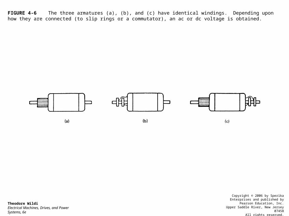
FIGURE 4-6 The three armatures (a), (b), and (c) have identical windings. Depending upon how they are connected (to slip rings or a commutator), an ac or dc voltage is obtained.
Theodore WildiElectrical Machines, Drives, and Power Systems, 6e
Copyright © 2006 by Sperika Enterprises and published by Pearson Education, Inc.
Upper Saddle River, New Jersey 07458All rights reserved.

FIGURE 4-7 Schematic diagram of a dc generator having 4 coils and 4 commutator bars. See Fig. 4.9.
Theodore WildiElectrical Machines, Drives, and Power Systems, 6e
Copyright © 2006 by Sperika Enterprises and published by Pearson Education, Inc.
Upper Saddle River, New Jersey 07458All rights reserved.
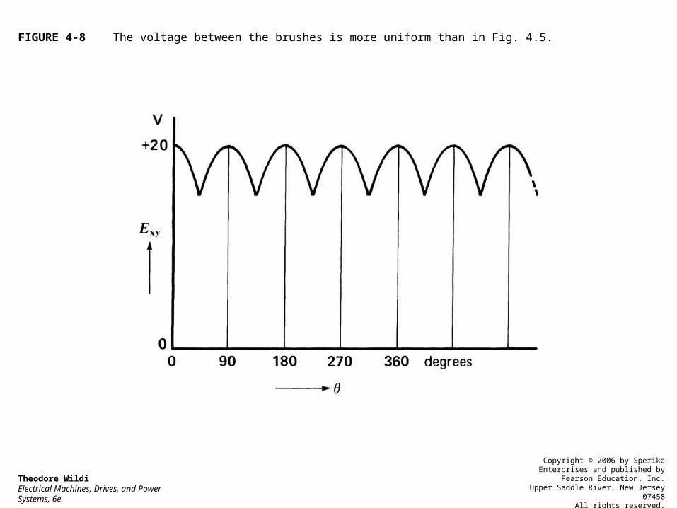
FIGURE 4-8 The voltage between the brushes is more uniform than in Fig. 4.5.
Theodore WildiElectrical Machines, Drives, and Power Systems, 6e
Copyright © 2006 by Sperika Enterprises and published by Pearson Education, Inc.
Upper Saddle River, New Jersey 07458All rights reserved.

FIGURE 4-9 The actual physical construction of the generator shown in Fig. 4.7. The armature has 4 slots, 4 coils, and 4 commutator bars.
Theodore WildiElectrical Machines, Drives, and Power Systems, 6e
Copyright © 2006 by Sperika Enterprises and published by Pearson Education, Inc.
Upper Saddle River, New Jersey 07458All rights reserved.
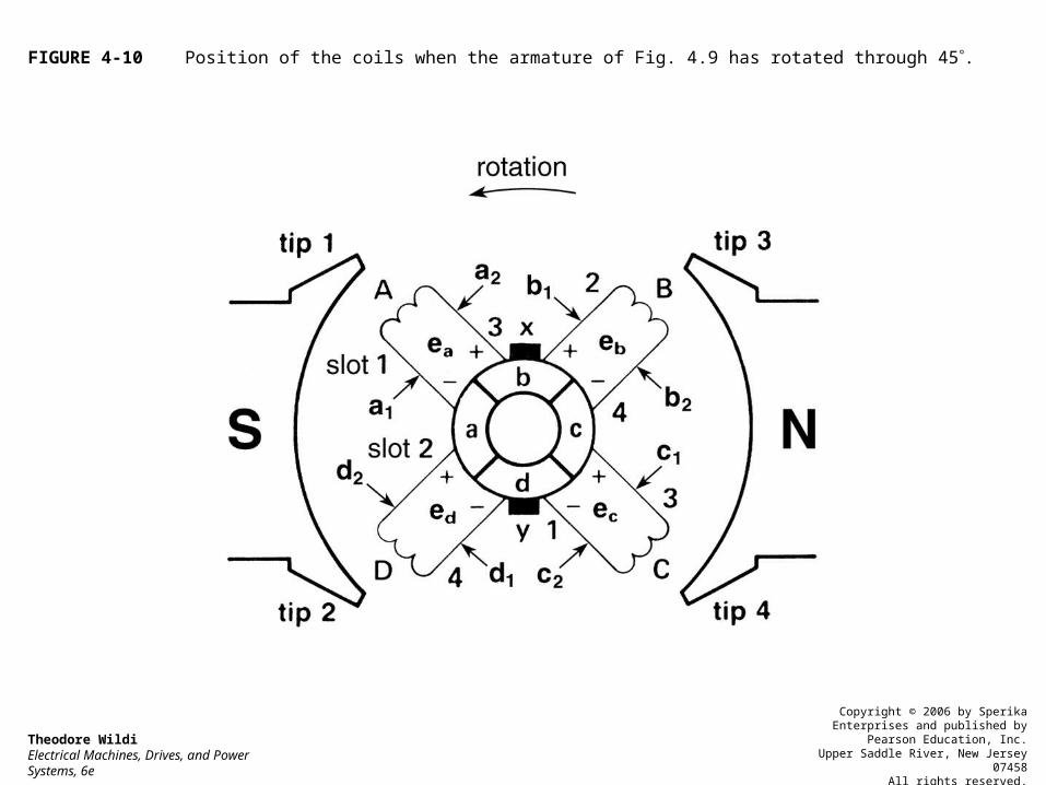
FIGURE 4-10 Position of the coils when the armature of Fig. 4.9 has rotated through 45.
Theodore WildiElectrical Machines, Drives, and Power Systems, 6e
Copyright © 2006 by Sperika Enterprises and published by Pearson Education, Inc.
Upper Saddle River, New Jersey 07458All rights reserved.

FIGURE 4-14 Magnetic field produced by the current flowing in the armature conductors.
Theodore WildiElectrical Machines, Drives, and Power Systems, 6e
Copyright © 2006 by Sperika Enterprises and published by Pearson Education, Inc.
Upper Saddle River, New Jersey 07458All rights reserved.

FIGURE 4-15 Armature reaction distorts the field produced by the N, S poles.
Theodore WildiElectrical Machines, Drives, and Power Systems, 6e
Copyright © 2006 by Sperika Enterprises and published by Pearson Education, Inc.
Upper Saddle River, New Jersey 07458All rights reserved.
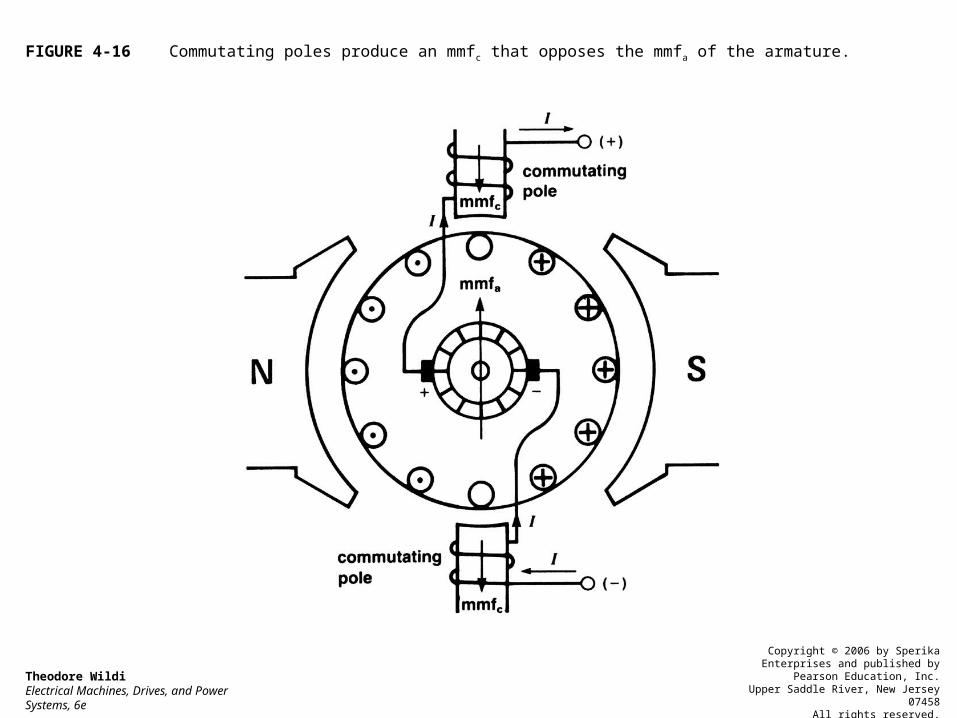
FIGURE 4-16 Commutating poles produce an mmfc that opposes the mmfa of the armature.
Theodore WildiElectrical Machines, Drives, and Power Systems, 6e
Copyright © 2006 by Sperika Enterprises and published by Pearson Education, Inc.
Upper Saddle River, New Jersey 07458All rights reserved.

FIGURE 4-17 Separately excited 2-pole generator. The N, S field poles are created by the current flowing in the field windings.
Theodore WildiElectrical Machines, Drives, and Power Systems, 6e
Copyright © 2006 by Sperika Enterprises and published by Pearson Education, Inc.
Upper Saddle River, New Jersey 07458All rights reserved.

FIGURE 4-18a Flux per pole versus exciting current.
Theodore WildiElectrical Machines, Drives, and Power Systems, 6e
Copyright © 2006 by Sperika Enterprises and published by Pearson Education, Inc.
Upper Saddle River, New Jersey 07458All rights reserved.

FIGURE 4-18b Saturation curve of a dc generator.
Theodore WildiElectrical Machines, Drives, and Power Systems, 6e
Copyright © 2006 by Sperika Enterprises and published by Pearson Education, Inc.
Upper Saddle River, New Jersey 07458All rights reserved.

FIGURE 4-19 a. Self-excited shunt generator. b. Schematic diagram of a shunt generator. A shunt field is one designed to be connected in shunt (alternate term for parallel) with the armature winding.
Theodore WildiElectrical Machines, Drives, and Power Systems, 6e
Copyright © 2006 by Sperika Enterprises and published by Pearson Education, Inc.
Upper Saddle River, New Jersey 07458All rights reserved.
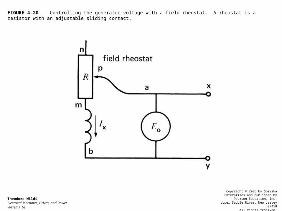
FIGURE 4-20 Controlling the generator voltage with a field rheostat. A rheostat is a resistor with an adjustable sliding contact.
Theodore WildiElectrical Machines, Drives, and Power Systems, 6e
Copyright © 2006 by Sperika Enterprises and published by Pearson Education, Inc.
Upper Saddle River, New Jersey 07458All rights reserved.

FIGURE 4-21 The no-load voltage depends upon the resistance of the shunt-field circuit.
Theodore WildiElectrical Machines, Drives, and Power Systems, 6e
Copyright © 2006 by Sperika Enterprises and published by Pearson Education, Inc.
Upper Saddle River, New Jersey 07458All rights reserved.

FIGURE 4-22 Equivalent circuit of a dc generator.
Theodore WildiElectrical Machines, Drives, and Power Systems, 6e
Copyright © 2006 by Sperika Enterprises and published by Pearson Education, Inc.
Upper Saddle River, New Jersey 07458All rights reserved.

FIGURE 4-23 Separately excited generator under load.
Theodore WildiElectrical Machines, Drives, and Power Systems, 6e
Copyright © 2006 by Sperika Enterprises and published by Pearson Education, Inc.
Upper Saddle River, New Jersey 07458All rights reserved.

FIGURE 4-24 Load characteristic of a separately excited generator.
Theodore WildiElectrical Machines, Drives, and Power Systems, 6e
Copyright © 2006 by Sperika Enterprises and published by Pearson Education, Inc.
Upper Saddle River, New Jersey 07458All rights reserved.

FIGURE 4-25 a. Compound generator under load. b. Schematic diagram.
Theodore WildiElectrical Machines, Drives, and Power Systems, 6e
Copyright © 2006 by Sperika Enterprises and published by Pearson Education, Inc.
Upper Saddle River, New Jersey 07458All rights reserved.

FIGURE 4-26 Typical load characteristics of dc generators.
Theodore WildiElectrical Machines, Drives, and Power Systems, 6e
Copyright © 2006 by Sperika Enterprises and published by Pearson Education, Inc.
Upper Saddle River, New Jersey 07458All rights reserved.

FIGURE 4-27 Cross section of a 2-pole generator.
Theodore WildiElectrical Machines, Drives, and Power Systems, 6e
Copyright © 2006 by Sperika Enterprises and published by Pearson Education, Inc.
Upper Saddle River, New Jersey 07458All rights reserved.

FIGURE 4-28 Cutaway view of a 4-pole shunt generator. It has 3 brushes per brush set.
Theodore WildiElectrical Machines, Drives, and Power Systems, 6e
Copyright © 2006 by Sperika Enterprises and published by Pearson Education, Inc.
Upper Saddle River, New Jersey 07458All rights reserved.

FIGURE 4-29 Adjacent poles of multipole generators have opposite magnetic polarities.
Theodore WildiElectrical Machines, Drives, and Power Systems, 6e
Copyright © 2006 by Sperika Enterprises and published by Pearson Education, Inc.
Upper Saddle River, New Jersey 07458All rights reserved.
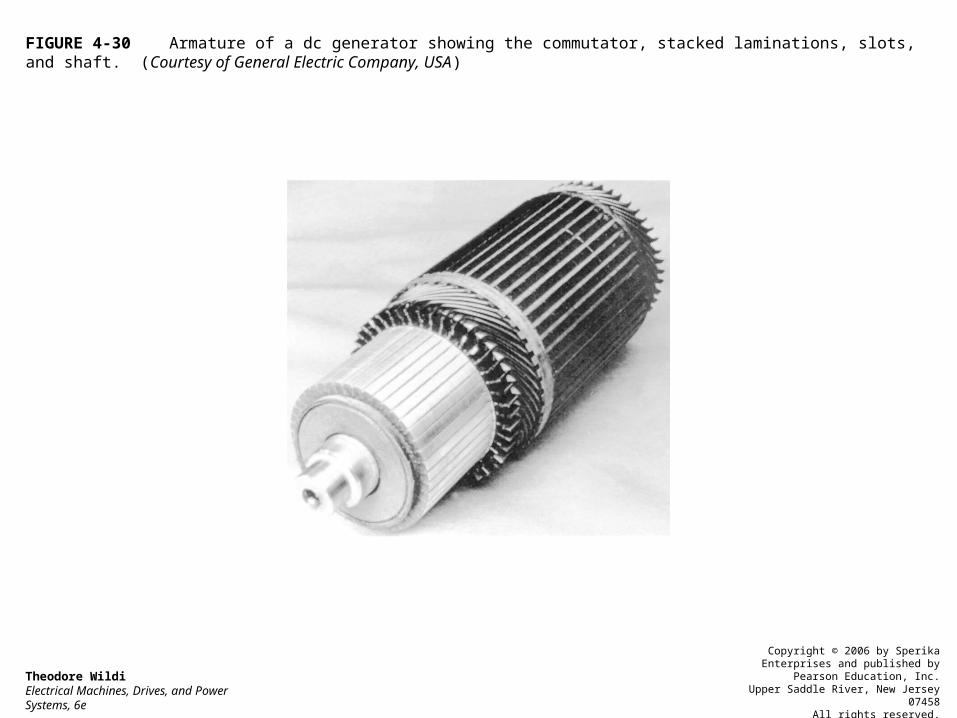
FIGURE 4-30 Armature of a dc generator showing the commutator, stacked laminations, slots, and shaft. (Courtesy of General Electric Company, USA)
Theodore WildiElectrical Machines, Drives, and Power Systems, 6e
Copyright © 2006 by Sperika Enterprises and published by Pearson Education, Inc.
Upper Saddle River, New Jersey 07458All rights reserved.

FIGURE 4-31 Armature laminations with tapered slots.
Theodore WildiElectrical Machines, Drives, and Power Systems, 6e
Copyright © 2006 by Sperika Enterprises and published by Pearson Education, Inc.
Upper Saddle River, New Jersey 07458All rights reserved.

FIGURE 4-32 Crosssection of a slot containing 4 conductors.
Theodore WildiElectrical Machines, Drives, and Power Systems, 6e
Copyright © 2006 by Sperika Enterprises and published by Pearson Education, Inc.
Upper Saddle River, New Jersey 07458All rights reserved.

FIGURE 4-33 Commutator of a dc machine.
Theodore WildiElectrical Machines, Drives, and Power Systems, 6e
Copyright © 2006 by Sperika Enterprises and published by Pearson Education, Inc.
Upper Saddle River, New Jersey 07458All rights reserved.

FIGURE 4-34 a. Brushes of a 2-pole generator. b. Brushes and connections of a 6-pole generator.
Theodore WildiElectrical Machines, Drives, and Power Systems, 6e
Copyright © 2006 by Sperika Enterprises and published by Pearson Education, Inc.
Upper Saddle River, New Jersey 07458All rights reserved.

FIGURE 4-35 a. Carbon brush and ultraflexible copper lead. b. Brush holder and spring to exert pressure. c. Brush set composed of two brushes, mounted on rocker arm. (Courtesy of General Electric Company, USA)
Theodore WildiElectrical Machines, Drives, and Power Systems, 6e
Copyright © 2006 by Sperika Enterprises and published by Pearson Education, Inc.
Upper Saddle River, New Jersey 07458All rights reserved.
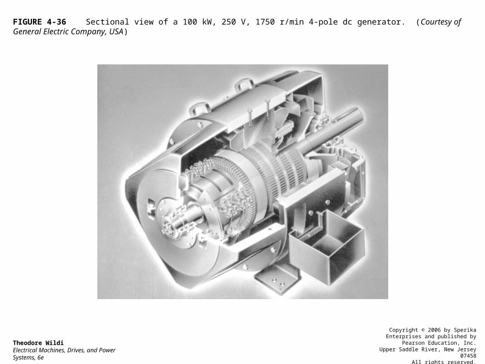
FIGURE 4-36 Sectional view of a 100 kW, 250 V, 1750 r/min 4-pole dc generator. (Courtesy of General Electric Company, USA)
Theodore WildiElectrical Machines, Drives, and Power Systems, 6e
Copyright © 2006 by Sperika Enterprises and published by Pearson Education, Inc.
Upper Saddle River, New Jersey 07458All rights reserved.

FIGURE 4-37 This direct-current Thompson generator was first installed in 1889 to light the streets of Montreal. It delivered a current of 250 A at a voltage of 110 V. Other properties of this pioneering machine include the following:Speed 1300 r/minTotal weight 2390 kgArmature diameter 292 mmStator internal diameter 330 mmNumber of commutator bars 76Armature conductor size # 4Shunt field conductor size # 14A modern generator having the same power and speed weighs 7 times less and occupies only 1/3 the floor space.
Theodore WildiElectrical Machines, Drives, and Power Systems, 6e
Copyright © 2006 by Sperika Enterprises and published by Pearson Education, Inc.
Upper Saddle River, New Jersey 07458All rights reserved.

FIGURE 4-38a Schematic diagram of a 12-pole, 72-coil dc generator.
Theodore WildiElectrical Machines, Drives, and Power Systems, 6e
Copyright © 2006 by Sperika Enterprises and published by Pearson Education, Inc.
Upper Saddle River, New Jersey 07458All rights reserved.
Electrical Machines and Energy Conversion
End of Presentation