eigerflex® 2.0 table of contents - rumit sl · table of contents 2.0 table of ... 2.200 pressure...
TRANSCRIPT

06.12.2010
EIGERFLEX® CPE
Subject to technical changes
Table of Contents
2.0 Table of Contents
2.1 System description 2.100 System description (general)2.105 System description (data)2.115 EIGERFLEX® DN 20 - DN 40 with frost protection strip, Ø carrier pipe 25 - 50 mm2.120 EIGERFLEX® DN 50 - DN 100 with frost protection strip in the frost protection strip channel, Ø carrier pipe 63 - 110 mm
2.2 Planning, design engineering2.200 Pressure loss chart, DN 20 - DN 100 (SDR 11)2.210 Heat loss
2.3 Components2.315 EIGERFLEX® L-shell, dimension Ø 76 - 126 mm2.316 EIGERFLEX® Big-L-shell, dimension Ø 162 mm2.320 Joint (PE-HD shrink sleeve), dimension Ø 76 - 126 mm2.325 EIGERFLEX® I-shell, dimension Ø 76 - 126 mm2.326 EIGERFLEX® Big-I-shell, dimension Ø 162 mm2.330 EIGERFLEX® T-shell, dimension Ø 76 - 126 mm2.335 EIGERFLEX® Big-T-shell, dimension Ø 162 mm2.345 Insulation material, PUR-foam containers / PE-Isolation2.350 PE-jointing methods 1, screwed connectors (external thread, weld end, coupling)2.355 PE-jointing methods 2, screwed connectors / T-pieces2.360 PE-jointing methods 3, fusion-welded and alternative connections2.365 End closure, shrink-type closure2.370 Wall sealing ring, pipe warning tape2.375 Building entry, wall opening/core bore2.380 Building entry, core bores/cement pipe liners
2.4 Underground construction, installation2.505 Trench dimensions2.510 Sleeve joint - frost protection strip 2.515 T-piece, frost protection strip2.520 Connection to end of frost protection strip
2.0
06.12.2010
EIGERFLEX® CPE
Subject to technical changes
2.100
System description
1. General
EIGERFLEX® is Brugg Pipe Systems protected name for a flexible, pre-insulated cold water pipe featuring an integrated frost protection strip (FPC). This pipe system is especially suitable for cold water and waste water pipes which cannot be installed at depths that are safe from frost.
The EIGERFLEX® cold water pipe features a medium pipe produced from high-density polyethy-lene (PE100) as per standard EN 12162. Polyethylene pressure pipes are the standard for drin-king water and waste water systems, and also for the gas supply sector, and they are excellently suited to the areas of application just mentioned. The pipes are joined by means of standardised screwed connectors, mechanical pipe couplings, with normal commercial electrowelded fittings or by means of polyfusion welding technology. The heat insulation consists of CFC-free flexible rigid polyurethane foam with excellent insu-lating properties. The bending capacity of the flexible EIGERFLEX® cold water pipe means that it can be adapted to all pipe routing conditions without problems. It is possible to pass over or under existing supply pipes, and obstacles are easily bypassed. With flexible EIGERFLEX® cold water pipe, you can choose the shortest pipe route without having to consider classical pipe construction methods.
The self-limiting frost protection strip (FPC) is used with different power capacities (11 or 18 W/m), regardless of the thickness of the medium pipe or the insulation. EIGERFLEX® cold water pipe is prefabricated as appropriate and supplied in the required lengths; it always offers the same performance, regardless of the quantities ordered. The maximum length of the heating circuit varies according to the cut-in temperature, which must be controlled by a thermostat.
The desired length of flexible EIGERFLEX® cold water pipe is delivered to site in continuous form, either in rings or on a cable drum. Thanks to the generous delivery lengths, pipes can be laid largely without connection points in the ground, so the width of the pipe trench can be considerably reduced. Substantial savings are possible because underground construction work is minimised and installation is fast as well as simple.
2. Range of applications
Max. continuous operatingtemperature TBmax: –20 to +20 °CMax. permitted operatingpressure p: max. 16 bar
06.12.2010
EIGERFLEX® CPE
Subject to technical changes
System description
1. Medium pipe
Material: Polyethylene class PE100 with high density, to DIN EN ISO 1216262Life expectancy: 50 years at 20 °C (16 bar) resp. 40 °C (11.6 bar) to DIN 8074 (SF 1.25)Characteristics: Suitable for cold water and sewage/waste water pipes
PE medium pipe
Density
Heat conductivity
Ultimate tensile strength (tearing resistance)
Modulus of elasticity
Linear expansion coefficient
Crystallite melting range
Ref. temp. °C
–
40 - 46
20
20
20
–
Value
952 - 960 kg/m³
0.40 W/mK
32 N/mm³
1000 N/mm³
1.8 · 10 E-4 1/K
130 - 135 °C
Test standard
DIN 53479
DIN 52612
DIN 53455
DIN 53457
DIN 52328
–
2. Frost protection strip
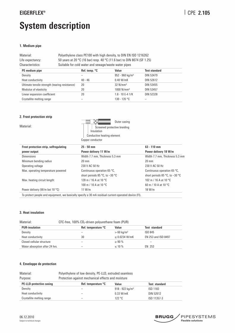
Material:
Frost protection strip, selfregulating
power output
Dimensions
Minimum bending radius
Operating voltage
Max. operating temperature powered
Max. heating circuit length:
Power delivery (W/m bei 10 °C)
25 - 50 mm
Power delivery 11 W/m
Width 7.7 mm, Thickness 5.3 mm
20 mm
230 V AC 50 Hz
Continuous operation 65 °C,
short periods 85 °C, to –30 °C
128 m / 16 A at 10 °C
100 m / 10 A at 10 °C
11 W/m
63 - 110 mm
Power delivery 18 W/m
Width 7.7 mm, Thickness 5.3 mm
20 mm
230 V AC 50 Hz
Continuous operation 65 °C,
short periods 85 °C, to –30 °C
102 m / 16 A at 10 °C
60 m / 10 A at 10 °C
18 W/m
To protect people and equipment, we basically specify a 30 mA residual current-operated device (FI).
3. Heat insulation
Material: CFC-free, 100% CO2-driven polyurethane foam (PUR)
PUR-insulation
Density
Heat conductivity
Closed cellular structure
Water absorption after 24 hrs.
Ref. temperature °C
–
30
–
–
Value
> 60 kg/m³
≤ 0.0234 W/mK
≥ 90 %
≤ 10 %
Test standard
ISO 845
EN 253 and ISO 8497
–
EN 253
4. Enveloppe de protection
Material: Polyethylene of low density, PE-LLD, extruded seamless Purpose: Protection against mechanical effects and moisture
PE-LLD-protective casing
Density
Heat conductivity
Crystallite melting range
Ref. temperature °C
–
–
–
Value
918 - 922 kg/m³
0.33 W/mK
122 °C
Test standard
ISO 1183
DIN 52612
ISO 11357-3
Outer casing
InsulationConductive heating element
Copper conductor
Screened protective braiding
2.105
06.12.2010
EIGERFLEX® CPE
Subject to technical changes
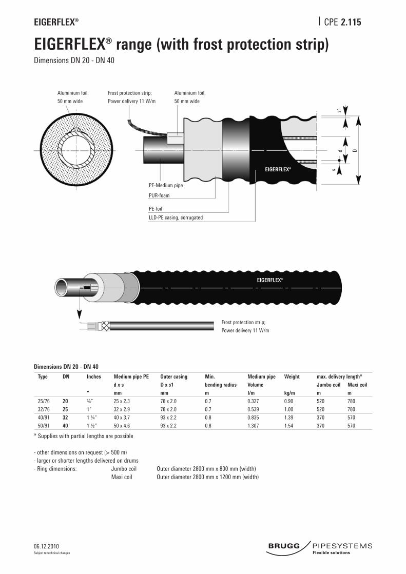
EIGERFLEX® range (with frost protection strip)
2.115
Dimensions DN 20 - DN 40
Dimensions DN 20 - DN 40
Type
25/76
32/76
40/91
50/91
DN
20
25
32
40
Inches
“
¾“
1“
1 ¼“
1 ½“
Medium pipe PE
d x s
mm
25 x 2.3
32 x 2.9
40 x 3.7
50 x 4.6
Outer casing
D x s1
mm
78 x 2.0
78 x 2.0
93 x 2.2
93 x 2.2
Min.
bending radius
m
0.7
0.7
0.8
0.8
Medium pipe
Volume
I/m
0.327
0.539
0.835
1.307
Weight
kg/m
0.90
1.00
1.39
1.54
max. delivery length*
Jumbo coil Maxi coil
m m
520 780
520 780
370 570
370 570
* Supplies with partial lengths are possible
- other dimensions on request (> 500 m)- larger or shorter lengths delivered on drums- Ring dimensions: Jumbo coil Outer diameter 2800 mm x 800 mm (width) Maxi coil Outer diameter 2800 mm x 1200 mm (width)
Aluminium foil,
50 mm wide
Frost protection strip;
Power delivery 11 W/m
Aluminium foil,
50 mm wide
PE-Medium pipe
PUR-foam
PE-foil
LLD-PE casing, corrugated
sd D
s1
Frost protection strip;
Power delivery 11 W/m
EIGERFLEX®
EIGERFLEX®

06.12.2010
EIGERFLEX® CPE
Subject to technical changes
2.120
EIGERFLEX® range (with frost protection strip)Dimensions DN 50 - DN 100
Aluminium foil,
102 mm wide
Frost protection strip;
Power delivery 17 W/m
Aluminium foil,
102 mm wide
PE-Medium pipe
PUR-foam
PE-foil
LLD-PE casing, corrugated
sd D
s1Frost protection strip;
Power delivery 17 W/m
Plastic channel
Frost protection strip channel18
∞
Dimensions DN 50 - DN 100
Type
63/126
75/126
90/162
110/162
DN
50
65
80
100
Inches
“
2“
2½“
3“
4“
Medium pipe PE
d x s
mm
63 x 5.8
75 x 6.8
90 x 8.2
110 x 10.0
Outer casing
D x s1
mm
128 x 2.7
128 x 2.7
163 x 3.2
163 x 3.2
Min.
bending radius
m
1.0
1.0
1.2
1.2
Medium pipe
Volume
I/m
2.091
2.961
4.254
6.362
Weight
kg/m
2.60
2.75
4.56
5.69
max.delivery length*
Jumbo coil Maxi coil
m m
192 291
192 291
92 149
92 149
* Supplies with partial lengths are possible
- other dimensions on request (> 500 m)- larger or shorter lengths delivered on drums- Ring dimensions: Jumbo coil Outer diameter 2800 mm x 800 mm (width) Maxi coil Outer diameter 2800 mm x 1200 mm (width)
EIGERFLEX®
EIGERFLEX®
06.12.2010
EIGERFLEX® CPE
Subject to technical changes
2.200
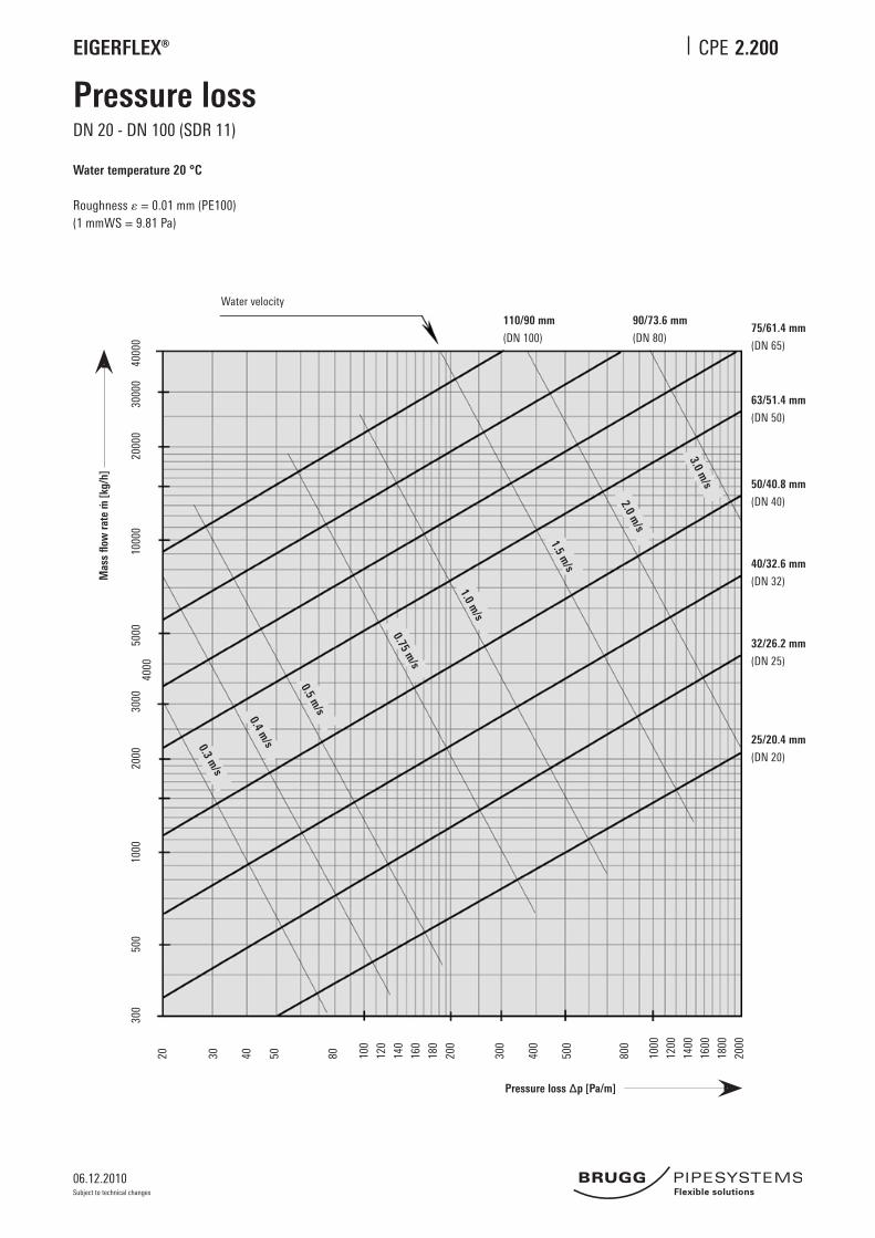
Pressure loss
Water temperature 20 °C
Roughness = 0.01 mm (PE100)(1 mmWS = 9.81 Pa)
Water velocity
Pressure loss ∆p [Pa/m]
2000
030
000
4000
010
000
5000
4000
3000
2000
1000
500
300
20 30 40 50 80 100
200
300
1000
2000
800
500
400
120
140
160
180
1200
1400
1600
1800
25/20.4 mm
(DN 20)
32/26.2 mm
(DN 25)
40/32.6 mm
(DN 32)
50/40.8 mm
(DN 40)
63/51.4 mm
(DN 50)
75/61.4 mm
(DN 65)
90/73.6 mm
(DN 80)
110/90 mm
(DN 100)
3.0 m/s
2.0 m/s
1.5 m/s
1.0 m/s
0.75 m/s
0.5 m/s
0.4 m/s0.3 m
/s
DN 20 - DN 100 (SDR 11)
Mas
s flo
w ra
te m
[kg
/h]
06.12.2010
EIGERFLEX® CPE
Subject to technical changes
2.210
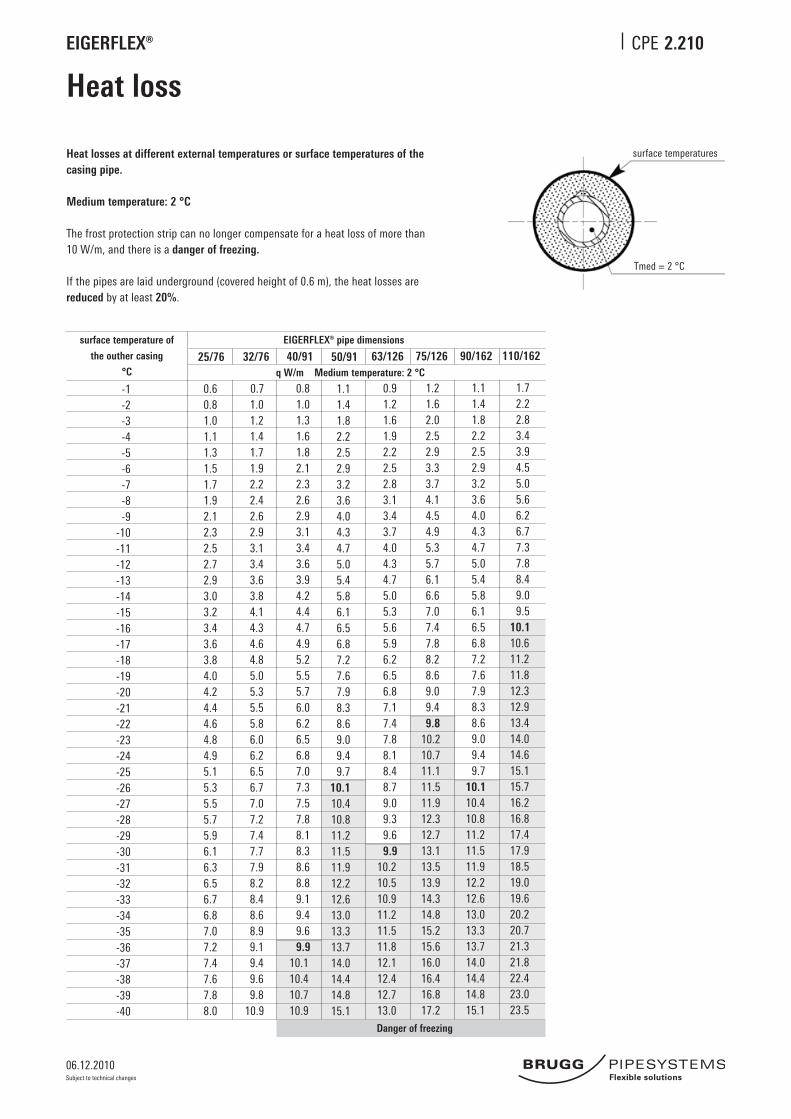
Heat loss
Heat losses at different external temperatures or surface temperatures of the casing pipe.
Medium temperature: 2 °C
The frost protection strip can no longer compensate for a heat loss of more than 10 W/m, and there is a danger of freezing.
If the pipes are laid underground (covered height of 0.6 m), the heat losses are reduced by at least 20%.
surface temperature of
the outher casing
°C25/76
0.6 0.8 1.0 1.1 1.3 1.5 1.7 1.9 2.1 2.3 2.5 2.7 2.9 3.0 3.2 3.4 3.6 3.8 4.0 4.2 4.4 4.6 4.8 4.9 5.1 5.3 5.5 5.7 5.9 6.1 6.3 6.5 6.7 6.8 7.0 7.2 7.4 7.6 7.8 8.0
32/76
0.7 1.0 1.2 1.4 1.7 1.9 2.2 2.4 2.6 2.9 3.1 3.4 3.6 3.8 4.1 4.3 4.6 4.8 5.0 5.3 5.5 5.8 6.0 6.2 6.5 6.7 7.0 7.2 7.4 7.7 7.9 8.2 8.4 8.6 8.9 9.1 9.4 9.6 9.8 10.9
40/91
0.8 1.0 1.3 1.6 1.8 2.1 2.3 2.6 2.9 3.1 3.4 3.6 3.9 4.2 4.4 4.7 4.9 5.2 5.5 5.7 6.0 6.2 6.5 6.8 7.0 7.3 7.5 7.8 8.1 8.3 8.6 8.8 9.1 9.4 9.6 9.9 10.1 10.4 10.7 10.9
63/126
0.9 1.2 1.6 1.9 2.2 2.5 2.8 3.1 3.4 3.7 4.0 4.3 4.7 5.0 5.3 5.6 5.9 6.2 6.5 6.8 7.1 7.4 7.8 8.1 8.4 8.7 9.0 9.3 9.6 9.9 10.2 10.5 10.9 11.2 11.5 11.8 12.1 12.4 12.7 13.0
75/126
1.2 1.6 2.0 2.5 2.9 3.3 3.7 4.1 4.5 4.9 5.3 5.7 6.1 6.6 7.0 7.4 7.8 8.2 8.6 9.0 9.4 9.8 10.2 10.7 11.1 11.5 11.9 12.3 12.7 13.1 13.5 13.9 14.3 14.8 15.2 15.6 16.0 16.4 16.8 17.2
90/162
1.1 1.4 1.8 2.2 2.5 2.9 3.2 3.6 4.0 4.3 4.7 5.0 5.4 5.8 6.1 6.5 6.8 7.2 7.6 7.9 8.3 8.6 9.0 9.4 9.7 10.1 10.4 10.8 11.2 11.5 11.9 12.2 12.6 13.0 13.3 13.7 14.0 14.4 14.8 15.1
110/162
1.7 2.2 2.8 3.4 3.9 4.5 5.0 5.6 6.2 6.7 7.3 7.8 8.4 9.0 9.5 10.1 10.6 11.2 11.8 12.3 12.9 13.4 14.0 14.6 15.1 15.7 16.2 16.8 17.4 17.9 18.5 19.0 19.6 20.2 20.7 21.3 21.8 22.4 23.0 23.5
-1-2-3-4-5-6-7-8-9
-10-11-12-13-14-15-16-17-18-19-20-21-22-23-24-25-26-27-28-29-30-31-32-33-34-35-36-37-38-39-40
EIGERFLEX® pipe dimensions
50/91 1.1 1.4 1.8 2.2 2.5 2.9 3.2 3.6 4.0 4.3 4.7 5.0 5.4 5.8 6.1 6.5 6.8 7.2 7.6 7.9 8.3 8.6 9.0 9.4 9.7 10.1 10.4 10.8 11.2 11.5 11.9 12.2 12.6 13.0 13.3 13.7 14.0 14.4 14.8 15.1
q W/m Medium temperature: 2 °C
surface temperatures
Tmed = 2 °C
Danger of freezing

06.12.2010
EIGERFLEX® CPE
Subject to technical changes
2.315
EIGERFLEX® L-shellDimension DN 20 - DN 65 (Ø 76 - 126 mm)
EIGERFLEX® L-shell Structure of the half-shell
1 ABS-half-shells2 Electro-fusion-joints; see CPE 2.360 3 Sealing clamps (14 pcs.)4 Insulation material; see CPE 2.3455 Glued surface6 Reducer ring or sealing ring7 Frost protection strip
d1
1
4
3
5
2
7
6
d2
376
376
Figures in mm
EIGERFLEX®
EIGE
RFLE
X®
Outer casing Ø d2
Ø d1 76 91 126
76 x
91 x
126 x
PE-jointing methods; see CPE 2.350 - 2.360
06.12.2010
EIGERFLEX® CPE
Subject to technical changes
2.316
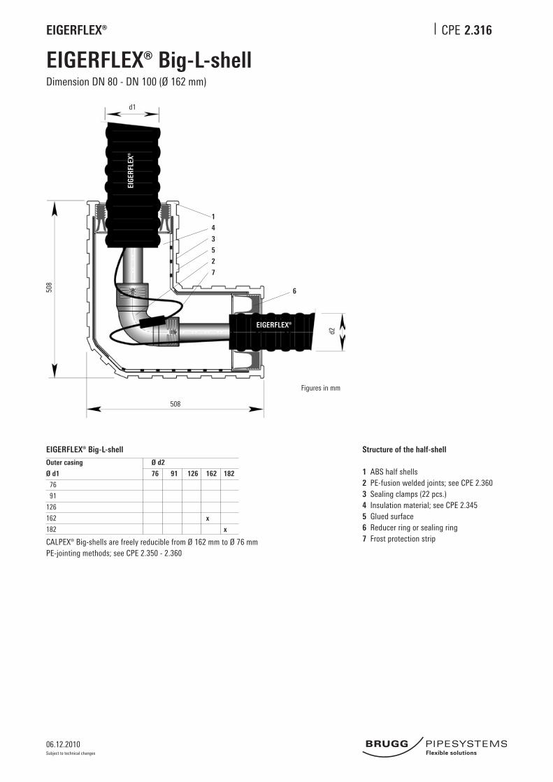
EIGERFLEX® Big-L-shellDimension DN 80 - DN 100 (Ø 162 mm)
EIGERFLEX® Big-L-shell Structure of the half-shell
1 ABS half shells2 PE-fusion welded joints; see CPE 2.360 3 Sealing clamps (22 pcs.)4 Insulation material; see CPE 2.3455 Glued surface6 Reducer ring or sealing ring 7 Frost protection strip
Outer casing Ø d2
Ø d1 76 91 126 162 182
76
91
126
162 x
182 x
CALPEX® Big-shells are freely reducible from Ø 162 mm to Ø 76 mmPE-jointing methods; see CPE 2.350 - 2.360
d1
1
4
3
5
2
7
6
d2
508
508
Figures in mm
EIGERFLEX®
EIGE
RFLE
X®

06.12.2010
EIGERFLEX® CPE
Subject to technical changes
2.320
Joint using PE-HD shrink sleeveDimension Ø 76 - 162 mm
EIGERFLEX® joints and reduction joints
Ø d2 76 91 126 162
Ø d1 76 x
91 x x
126 x x x
162 x x
EIGERFLEX®
1 2 3 4
d1 d2
EIGERFLEX®EIGERFLEX®
1 PE fusion welded joints; see CPE 2.3602 Insulation material, PUR or PE; see CPE 2.345 3 Shrink sleeve pipe4 Shrink hose
PE-jointing methods; see CPE 2.350 - 2.360
06.12.2010
EIGERFLEX® CPE
Subject to technical changes
2.325
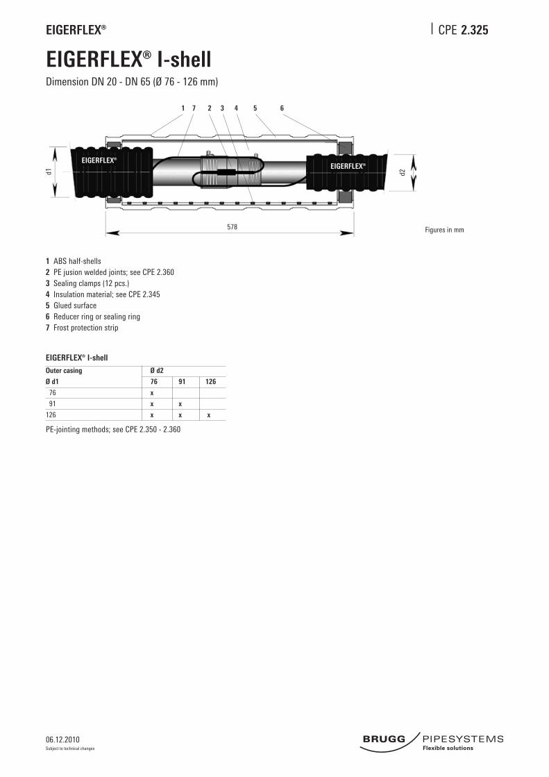
EIGERFLEX® I-shellDimension DN 20 - DN 65 (Ø 76 - 126 mm)
EIGERFLEX® I-shell
Outer casing Ø d2
Ø d1 76 91 126
76 x
91 x x
126 x x x
1 ABS half-shells2 PE jusion welded joints; see CPE 2.3603 Sealing clamps (12 pcs.)4 Insulation material; see CPE 2.3455 Glued surface6 Reducer ring or sealing ring7 Frost protection strip
Figures in mm
d2
1 27 543 6
d1
578
EIGERFLEX®EIGERFLEX®
PE-jointing methods; see CPE 2.350 - 2.360
06.12.2010
EIGERFLEX® CPE
Subject to technical changes
2.326
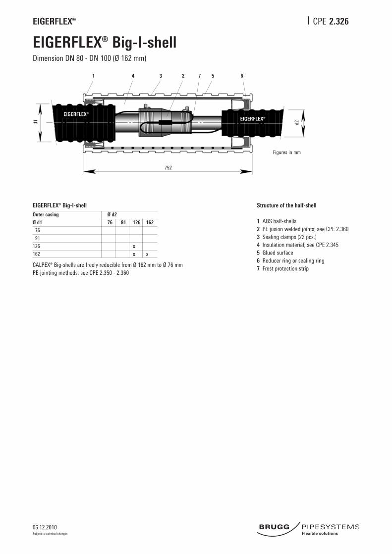
EIGERFLEX® Big-I-shellDimension DN 80 - DN 100 (Ø 162 mm)
EIGERFLEX® Big-I-shell Structure of the half-shell
1 ABS half-shells2 PE jusion welded joints; see CPE 2.360 3 Sealing clamps (22 pcs.)4 Insulation material; see CPE 2.3455 Glued surface6 Reducer ring or sealing ring7 Frost protection strip
Outer casing Ø d2
Ø d1 76 91 126 162
76
91
126 x
162 x x
CALPEX® Big-shells are freely reducible from Ø 162 mm to Ø 76 mmPE-jointing methods; see CPE 2.350 - 2.360
1 4 3 2 7 5 6
d2
752
Figures in mm
d1
EIGERFLEX®EIGERFLEX®
06.12.2010
EIGERFLEX® CPE
Subject to technical changes
2.330
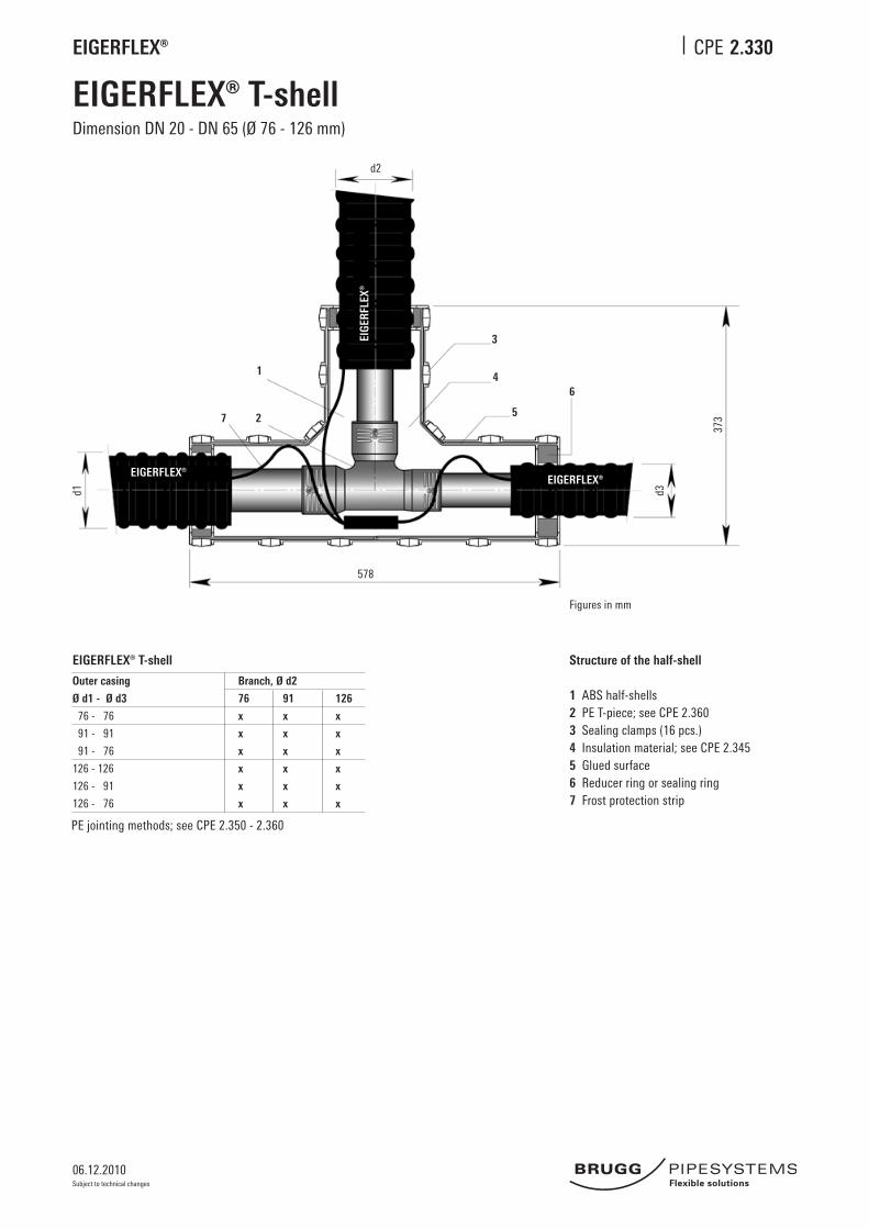
EIGERFLEX® T-shellDimension DN 20 - DN 65 (Ø 76 - 126 mm)
EIGERFLEX® T-shell
Outer casing Branch, Ø d2
Ø d1 - Ø d3 76 91 126
76 - 76 x x x
91 - 91 x x x
91 - 76 x x x
126 - 126 x x x
126 - 91 x x x
126 - 76 x x x
Structure of the half-shell
1 ABS half-shells2 PE T-piece; see CPE 2.360 3 Sealing clamps (16 pcs.)4 Insulation material; see CPE 2.3455 Glued surface6 Reducer ring or sealing ring7 Frost protection strip
Angaben in mm
1
2 5
4
3
6
d3d1
578
373
EIGERFLEX®EIGERFLEX®
EIGE
RFLE
X®
Figures in mm
d2
7
PE jointing methods; see CPE 2.350 - 2.360
06.12.2010
EIGERFLEX® CPE
Subject to technical changes
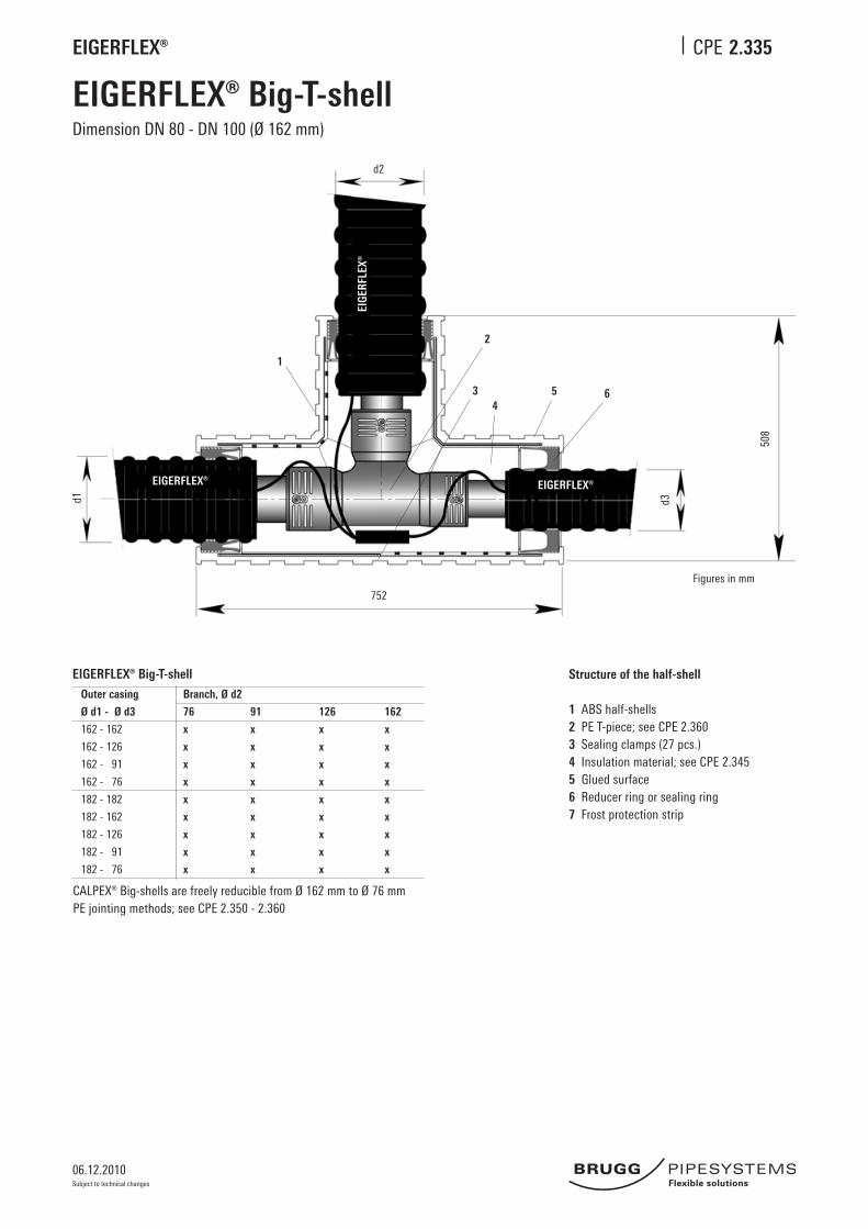
2.335
EIGERFLEX® Big-T-shellDimension DN 80 - DN 100 (Ø 162 mm)
EIGERFLEX® Big-T-shell
Outer casing Branch, Ø d2
Ø d1 - Ø d3 76 91 126 162
162 - 162 x x x x
162 - 126 x x x x
162 - 91 x x x x
162 - 76 x x x x
182 - 182 x x x x
182 - 162 x x x x
182 - 126 x x x x
182 - 91 x x x x
182 - 76 x x x x
Structure of the half-shell
1 ABS half-shells2 PE T-piece; see CPE 2.360 3 Sealing clamps (27 pcs.)4 Insulation material; see CPE 2.3455 Glued surface6 Reducer ring or sealing ring7 Frost protection strip
d1 d3
752
d2
508
1
2
34
5
Figures in mm
6
EIGERFLEX® EIGERFLEX®
EIGE
RFLE
X®
CALPEX® Big-shells are freely reducible from Ø 162 mm to Ø 76 mmPE jointing methods; see CPE 2.350 - 2.360
06.12.2010
EIGERFLEX® CPE
Subject to technical changes
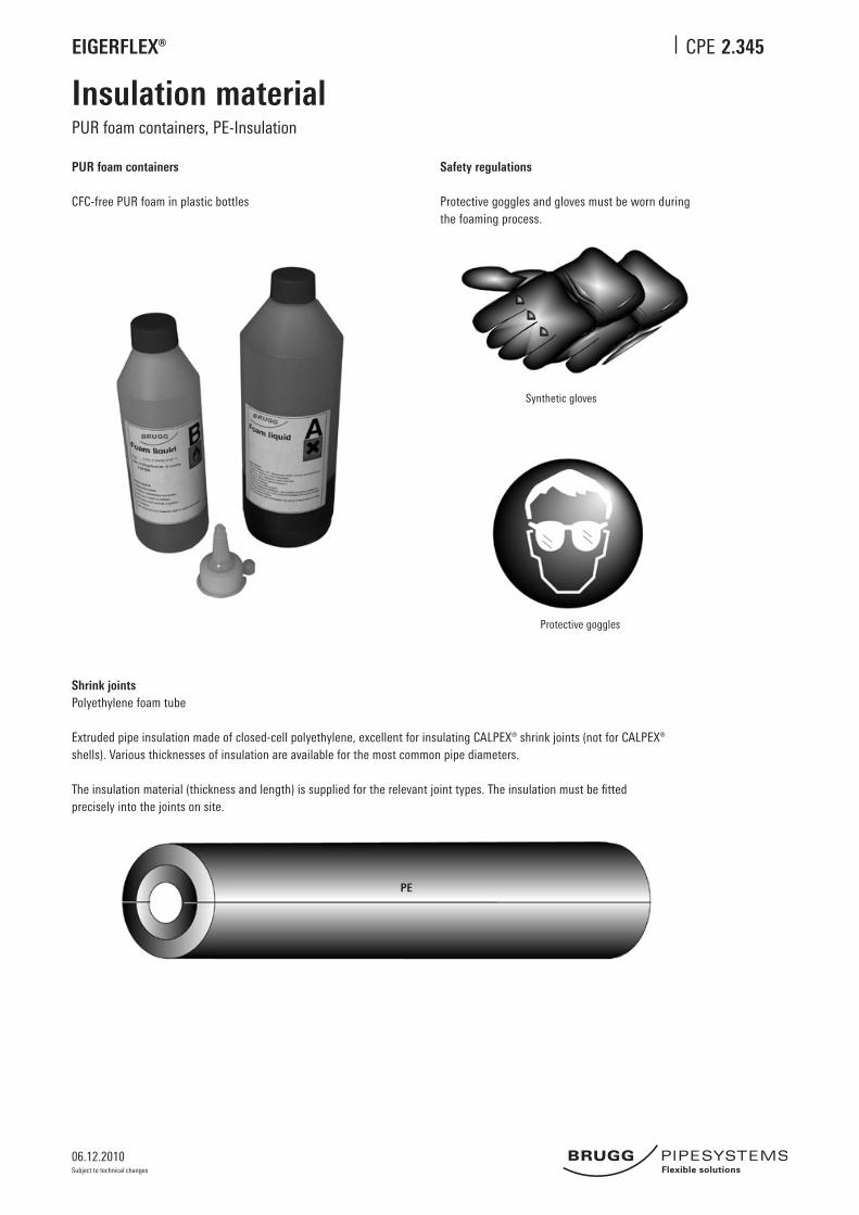
2.345
Insulation materialPUR foam containers, PE-Insulation
PUR foam containers
CFC-free PUR foam in plastic bottles
Safety regulations
Protective goggles and gloves must be worn during the foaming process.
Synthetic gloves
Protective goggles
Shrink jointsPolyethylene foam tube
Extruded pipe insulation made of closed-cell polyethylene, excellent for insulating CALPEX® shrink joints (not for CALPEX® shells). Various thicknesses of insulation are available for the most common pipe diameters.
The insulation material (thickness and length) is supplied for the relevant joint types. The insulation must be fitted precisely into the joints on site.
PE

06.12.2010
EIGERFLEX® CPE
Subject to technical changes
2.350
PE jointing methodsScrewed connectors (outer thread, weld end, coupling)
Connection with outer thread/weld end Heating, 6 bar
Material: brass
PE-pipe Screwed connector L Weld end L
mm mm mm mm mm
25 x 2.3 25 x 2.3-¾“ 53 26.9 x 2.65 180
32 x 2.9 32 x 2.9-1“ 63 33.7 x 2.3 180
40 x 3.7 40 x 3.7-1¼“ 67 42.4 x 2.6 185
50 x 4.6 50 x 4.6-1½“ 71 48.3 x 2.6 190
63 x 5.8 63 x 5.7-2“ 80 60.3 x 2.9 195
75 x 6.8 75 x 6.8-2½“ 92 76.1 x 3.2 200
90 x 8.2 90 x 8.2-3“ 92 88.9 x 3.2 240
110 x 10.0 110 x 10.0-4“ 102 114.3 x 3.6 280
L
L
L
L
St 37.0
St 37.0
90° angle coupling
z
Heating, 6 bar
Material: brass
PE-pipe PE-pipe a z
mm mm mm mm
25 x 2.3 25 x 2.3 54 32
32 x 2.9 32 x 2.9 64 37
40 x 3.7 40 x 3.7 74 42
50 x 4.6 50 x 4.6 87 48
63 x 5.8 63 x 5.8 106 60
75 x 6.8 75 x 6.8 117 67
90 x 8.2 90 x 8.2 – –
110 x 10.0 110 x 10.0 – –
z
a
a
Coupling, equal
Heating, 6 bar
Material: brass
PE-pipe PE-pipe L
mm mm mm
25 x 2.3 25 x 2.3 60
32 x 2.9 32 x 2.9 67
40 x 3.7 40 x 3.7 71
50 x 4.6 50 x 4.6 75
63 x 5.8 63 x 5.7 81
75 x 6.8 75 x 6.8 89
90 x 8.2 90 x 8.2 130
110 x 10.0 110 x 10.0 130
PE 22-75
PE 90-110
L
L
Coupling, reducedHeating, 6 bar
Material: brass
PE-pipe PE-pipe L
mm mm mm
32 x 2.9 25 x 2.3 86
40 x 3.7 32 x 2.9 87
50 x 4.6 40 x 3.7 96
63 x 5.8 50 x 4.6 110
75 x 6.8 63 x 5.8 140
90 x 8.2 75 x 6.8 175
110 x 10.0 90 x 8.2 315
PE 22-75
PE 90-110
L
L
06.12.2010
EIGERFLEX® CPE
Subject to technical changes
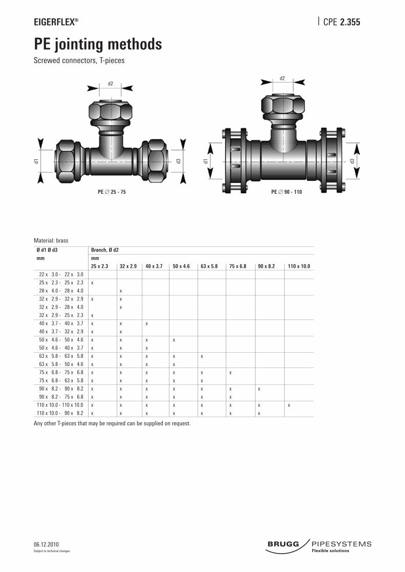
PE jointing methodsScrewed connectors, T-pieces
Material: brass
Ø d1 Ø d3 Branch, Ø d2
mm mm
25 x 2.3 32 x 2.9 40 x 3.7 50 x 4.6 63 x 5.8 75 x 6.8 90 x 8.2 110 x 10.0
22 x 3.0 - 22 x 3.0
25 x 2.3 - 25 x 2.3 x
28 x 4.0 - 28 x 4.0 x
32 x 2.9 - 32 x 2.9 x x
32 x 2.9 - 28 x 4.0 x
32 x 2.9 - 25 x 2.3 x
40 x 3.7 - 40 x 3.7 x x x
40 x 3.7 - 32 x 2.9 x x
50 x 4.6 - 50 x 4.6 x x x x
50 x 4.6 - 40 x 3.7 x x x
63 x 5.8 - 63 x 5.8 x x x x x
63 x 5.8 - 50 x 4.6 x x x x
75 x 6.8 - 75 x 6.8 x x x x x x
75 x 6.8 - 63 x 5.8 x x x x x
90 x 8.2 - 90 x 8.2 x x x x x x x
90 x 8.2 - 75 x 6.8 x x x x x x
110 x 10.0 - 110 x 10.0 x x x x x x x x
110 x 10.0 - 90 x 8.2 x x x x x x x
Any other T-pieces that may be required can be supplied on request.
PE 25 - 75 PE 90 - 110
d2d2
d1 d1d3 d3
2.355
06.12.2010
EIGERFLEX® CPE
Subject to technical changes
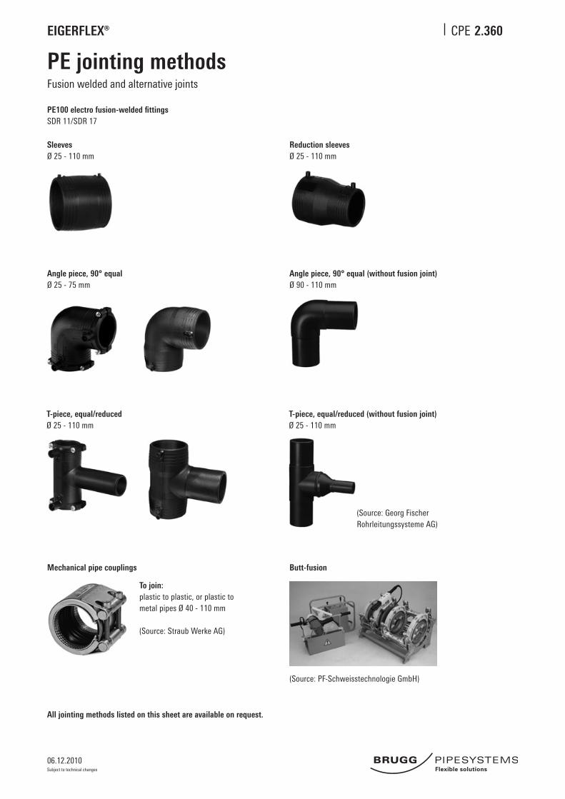
2.360
PE jointing methodsFusion welded and alternative joints
PE100 electro fusion-welded fittingsSDR 11/SDR 17
SleevesØ 25 - 110 mm
Mechanical pipe couplings
To join:plastic to plastic, or plastic to metal pipes Ø 40 - 110 mm
(Source: Straub Werke AG)
Reduction sleevesØ 25 - 110 mm
Angle piece, 90° equalØ 25 - 75 mm
T-piece, equal/reducedØ 25 - 110 mm
T-piece, equal/reduced (without fusion joint)Ø 25 - 110 mm
All jointing methods listed on this sheet are available on request.
Butt-fusion
(Source: PF-Schweisstechnologie GmbH)
Angle piece, 90° equal (without fusion joint)Ø 90 - 110 mm
(Source: Georg Fischer Rohrleitungssysteme AG)
06.12.2010
EIGERFLEX® CPE
Subject to technical changes
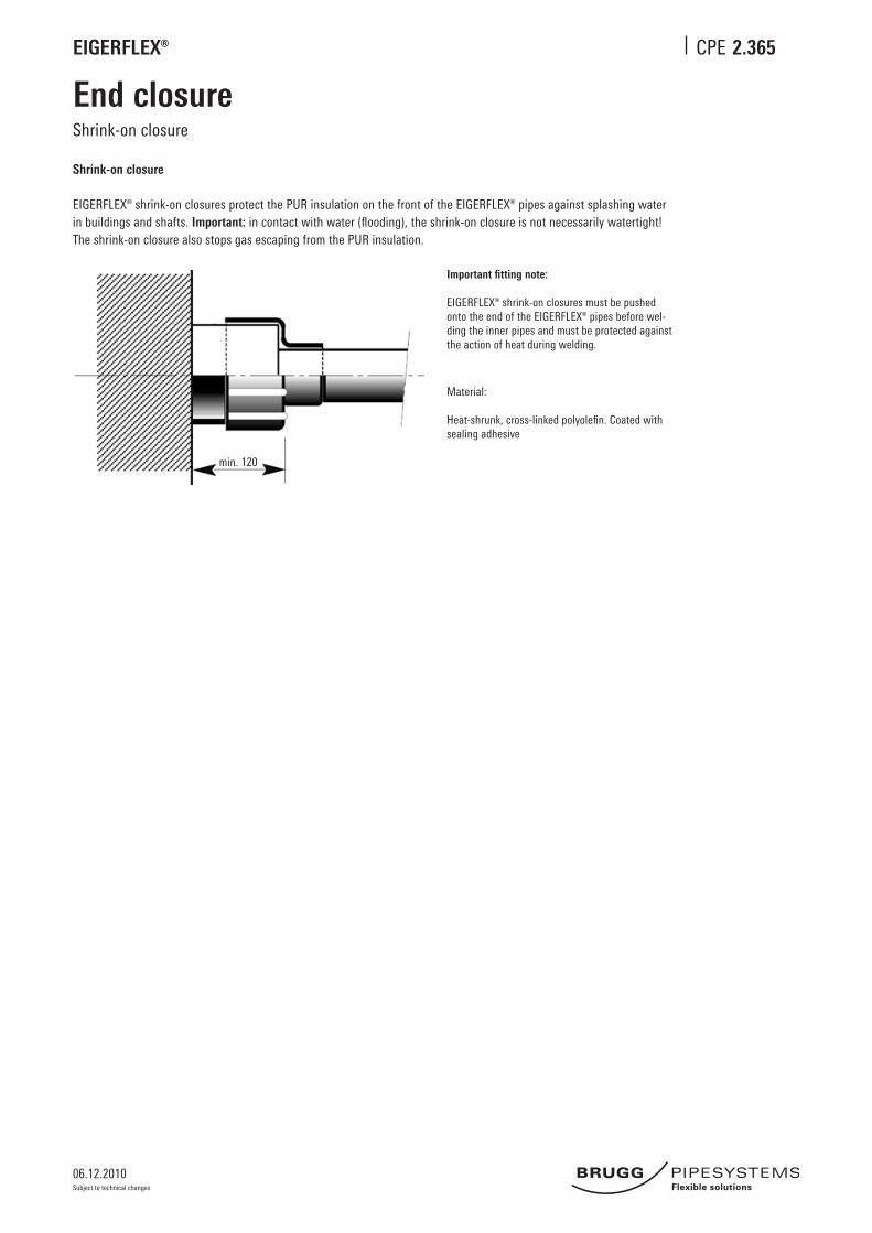
2.365
End closureShrink-on closure
Material:
Heat-shrunk, cross-linked polyolefin. Coated with sealing adhesive
Important fitting note:
EIGERFLEX® shrink-on closures must be pushed onto the end of the EIGERFLEX® pipes before wel-ding the inner pipes and must be protected against the action of heat during welding.
Shrink-on closure
EIGERFLEX® shrink-on closures protect the PUR insulation on the front of the EIGERFLEX® pipes against splashing water in buildings and shafts. Important: in contact with water (flooding), the shrink-on closure is not necessarily watertight! The shrink-on closure also stops gas escaping from the PUR insulation.
min. 120
06.12.2010
EIGERFLEX® CPE
Subject to technical changes
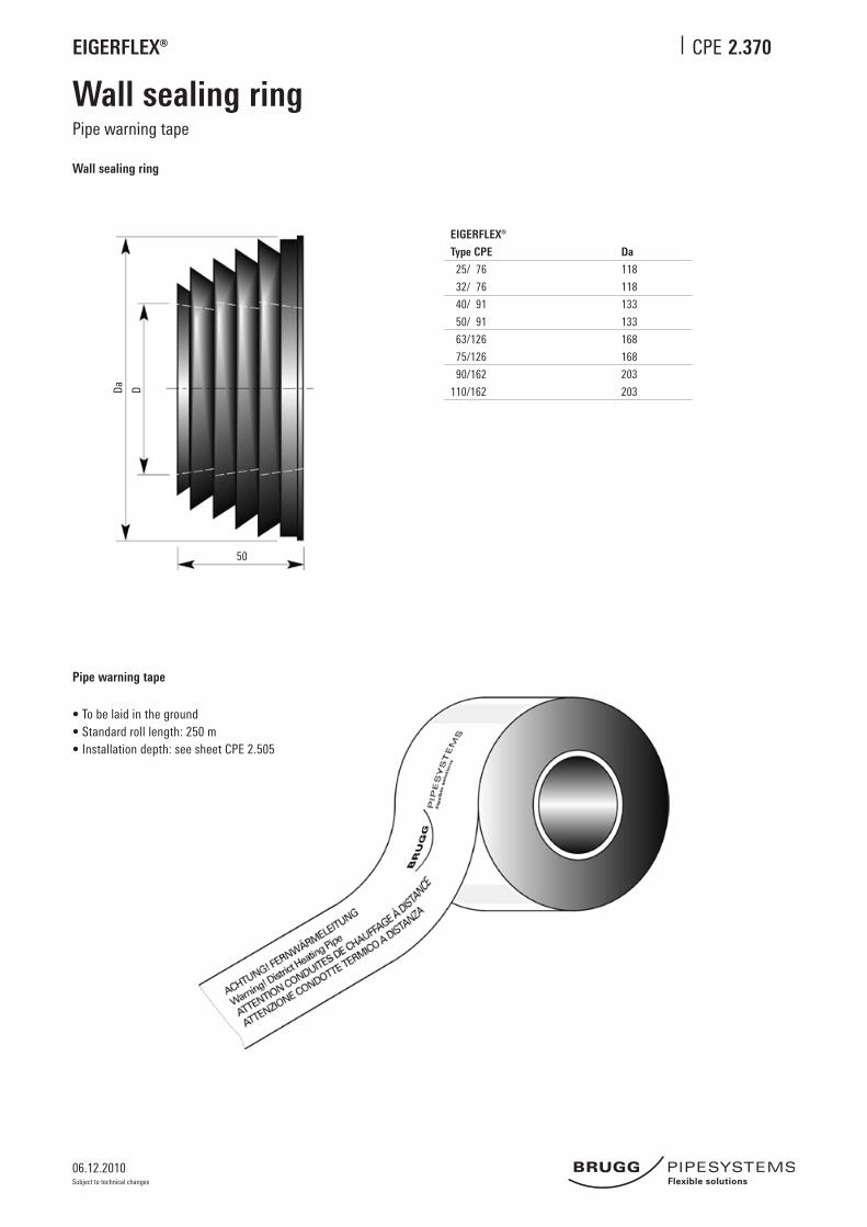
2.370
Wall sealing ringPipe warning tape
• To be laid in the ground • Standard roll length: 250 m • Installation depth: see sheet CPE 2.505
Pipe warning tape
Wall sealing ring
50
Da D
EIGERFLEX®
Type CPE
25/ 76
32/ 76
40/ 91
50/ 91
63/126
75/126
90/162
110/162
Da
118
118
133
133
168
168
203
203
06.12.2010
EIGERFLEX® CPE
Subject to technical changes
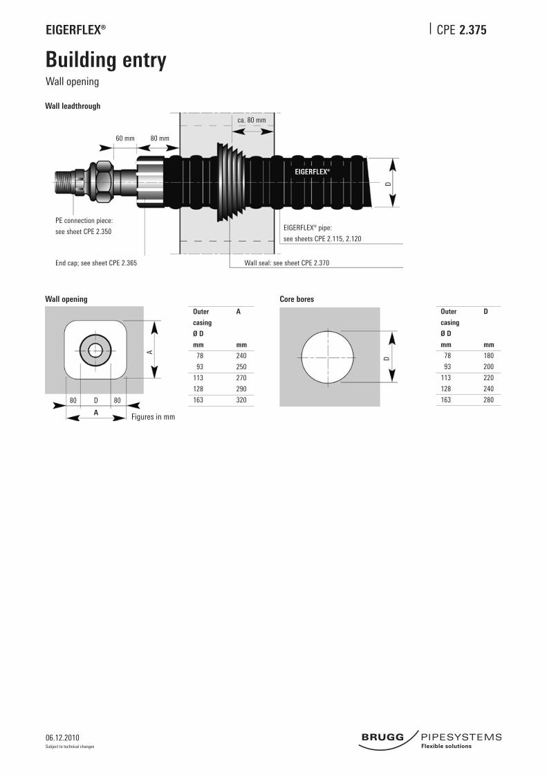
2.375
Building entry
Wall opening Core bores
Wall leadthrough
Outer
casing
Ø D
mm
78
93
113
128
163
A
mm
240
250
270
290
320
Outer
casing
Ø D
mm
78
93
113
128
163
D
mm
180
200
220
240
28080 D 80
A
A
D
PE connection piece:
see sheet CPE 2.350
End cap; see sheet CPE 2.365 Wall seal: see sheet CPE 2.370
EIGERFLEX® pipe:
see sheets CPE 2.115, 2.120
60 mm 80 mm
ca. 80 mm
D
EIGERFLEX®
Figures in mm
Wall opening

06.12.2010
EIGERFLEX® CPE
Subject to technical changes
2.380
Building entry
Wall leadthrough
Core bores/cement pipe liners
PE connection piece:
see sheet CPE 2.350
End cap:
see sheet CPE 2.365
EIGERFLEX® pipe:
see sheet CPE 2.115, 2.120
D
EIGERFLEX®
80 mm
Core bores
Core bores
Perfect bores are required for installation. As hairline cracks may be present in the concrete or result from drilling, it is advisable to seal the entire length of the borehole wall with suitable sealant (such as AQUAGARD).
Tightness can only be guaranteed if this recommendation is followed.
Outer casing D1 A
Ø D
mm mm mm
76 150 180
91 150 180
126 200 230
162 250 280
Key
1 EIGERFLEX® 2 Sealing set, single-seal, width 1 x 40 mm, Shore hardness D35 3 Sealing set, double-seal*, width 2 x 40 mm, Shore hardness D35 4 Liner pipe: made of fiber cement or coated core bore
* Suitable for pressure from water up to 0.5 bar
min. 30
A
D1
Figures in mm

06.12.2010
EIGERFLEX® CPE
Subject to technical changes
2.505
Trench dimensions
Trench profile, 1 CPE pipe
1 2 3
min
. 60
3010
10D
1010 D
B
T
Figures in cm
Casing pipe Width Depth Minimum
Ø D B T Bending radius
mm cm cm m
78 25 80 0.7
93 30 80 0.8
113 30 85 0.9
128 35 85 1.0
163 35 90 1.2
1 Pipe warning tape; see sheet CPE 2.3702 Excavated material3 Sand, washed, max. grain size 8 mm
SLW 30 = 300 kN total load as per DIN 1072; if subject to higher traffic loads (e.g. SLW 60), a load-distributing superstructure as per RStO75 is required.With no traffic load, the minimum trench depth T can be reduced by 20 cm.
Installation depth: max. installation depth: 2.6 m Our approval is required for installation at greater depths.
06.12.2010
EIGERFLEX® CPE
Subject to technical changes
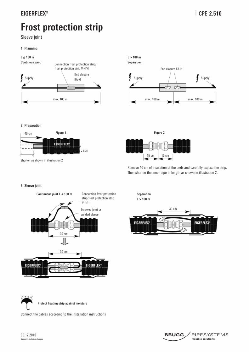
2.510
Frost protection stripSleeve joint
1. Planning
2. Preparation
3. Sleeve joint
Connect the cables according to the installation instructions
Remove 40 cm of insulation at the ends and carefully expose the strip. Then shorten the inner pipe to length as shown in illustration 2.
Shorten as shown in illustration 2
40 cm Figure 1 Figure 2
15 cm 15 cm
max. 100 m max. 100 m max. 100 m
L ≤ 100 m
Continous joint
L > 100 m
Separation
Supply
Connection frost protection strip/ frost protection strip V-H/H
End closure
EA-H Supply
End closure EA-H
Supply
Continuous joint L ≤ 100 m Separation
L > 100 m
Connection frost protection strip/frost protection strip V-H/H
Screwed joint or
welded sleeve
30 cm
30 cm
30 cm
Protect heating strip against moisture
EIGERFLEX®
EIGERFLEX® EIGERFLEX®
EIGERFLEX® EIGERFLEX®
frost protection strip/ frost protection strip V-H/H
06.12.2010
EIGERFLEX® CPE
Subject to technical changes
EIGERFLEX® EIGERFLEX®
EIGE
RFLE
X®
EIGERFLEX EIGERFLEX
EIGE
RFLE
X
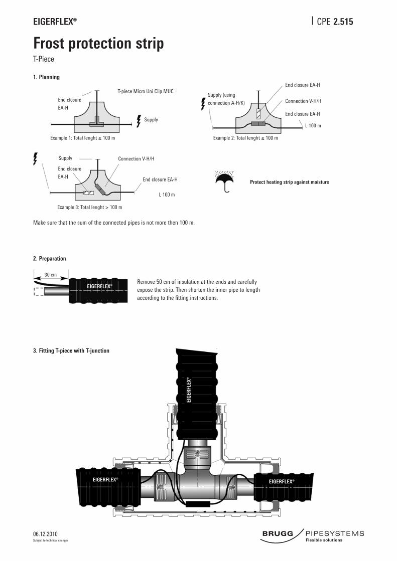
2.515
Frost protection stripT-Piece
1. Planning
Make sure that the sum of the connected pipes is not more then 100 m.
2. Preparation
3. Fitting T-piece with T-junction
Remove 50 cm of insulation at the ends and carefully expose the strip. Then shorten the inner pipe to length according to the fitting instructions.
Protect heating strip against moisture
30 cm
Example 3: Total lenght > 100 m
Supply
End closure
EA-H
Connection V-H/H
End closure EA-H
L 100 m
End closure
EA-H
T-piece Micro Uni Clip MUC
Supply
Example 1: Total lenght ≤ 100 m Example 2: Total lenght ≤ 100 m
L 100 m
End closure EA-H
Supply (using
connection A-H/K) Connection V-H/H
End closure EA-H
EIGERFLEX®
06.12.2010
EIGERFLEX® CPE
Subject to technical changes
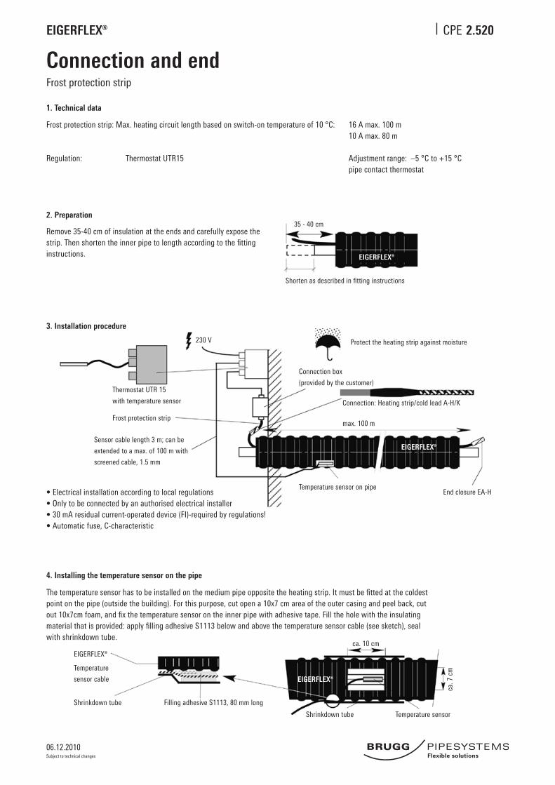
2.520
Connection and endFrost protection strip
1. Technical data
Frost protection strip: Max. heating circuit length based on switch-on temperature of 10 °C: 16 A max. 100 m 10 A max. 80 m
Regulation: Thermostat UTR15 Adjustment range: –5 °C to +15 °C pipe contact thermostat
2. Preparation
Remove 35-40 cm of insulation at the ends and carefully expose the strip. Then shorten the inner pipe to length according to the fitting instructions.
35 - 40 cm
Shorten as described in fitting instructions
• Electrical installation according to local regulations• Only to be connected by an authorised electrical installer• 30 mA residual current-operated device (FI)-required by regulations!• Automatic fuse, C-characteristic
4. Installing the temperature sensor on the pipe
The temperature sensor has to be installed on the medium pipe opposite the heating strip. It must be fitted at the coldest point on the pipe (outside the building). For this purpose, cut open a 10x7 cm area of the outer casing and peel back, cut out 10x7cm foam, and fix the temperature sensor on the inner pipe with adhesive tape. Fill the hole with the insulating material that is provided: apply filling adhesive S1113 below and above the temperature sensor cable (see sketch), seal with shrinkdown tube.
Protect the heating strip against moisture
Connection box
(provided by the customer)
Connection: Heating strip/cold lead A-H/K
max. 100 m
Temperature sensor on pipeEnd closure EA-H
Frost protection strip
Thermostat UTR 15
with temperature sensor
Sensor cable length 3 m; can be
extended to a max. of 100 m with
screened cable, 1.5 mm
230 V
EIGERFLEX®
Temperature
sensor cable
Shrinkdown tube Filling adhesive S1113, 80 mm long
Shrinkdown tube Temperature sensor
ca. 7
cm
ca. 10 cm
EIGERFLEX®
EIGERFLEX®
EIGERFLEX®
3. Installation procedure