effp electrical grease feed pump en operating instructions
TRANSCRIPT
ENEFFP electrical grease feed pump for the illing of pumps or for simple lubrication tasks
Operating instructions acc. to EC Dir. 2006/42/EC
Version 05
Page 2ENNotes
Masthead
These operating instructions pursuant to EC
Machinery Directive 2006/42/EC are an inte-
gral part of the described product and must be
kept for future use.
These operating instructions have been pre-
pared in accordance with the established stan-
dards and rules for technical documentation,
VDI 4500 and EN 292.
© SKF Lubrication Systems Germany GmbH
This documentation is protected by copyright.
SKF Lubrication Systems reserves all rights,
including those to the photomechanical repro-
duction, duplication, and distribution by means
of special procedures (e.g., data processing,
data media, and data networks) of this docu-
mentation in whole or in part.
Subject to changes in contents and technical
information.
Service
If you have technical questions, please contact
the following addresses:
SKF Lubrication Systems Germany GmbH
Berlin Plant Motzener Strasse 35/37
12277 Berlin
Germany
Tel. +49 (0)30 72002-0
Fax +49 (0)30 72002-111
www.skf.com/lubrication
Hockenheim Plant 2. Industriestrasse 4
68766 Hockenheim
Germany
Tel. +49 (0)62 05 27-0
Fax +49 (0)62 05 27-101
www.skf.com/lubrication
Page 3 ENTable of contents
Table of contentsEFFP electrical grease feed pump 1
Information concerning EC Declaration
of Conformity and EC Declaration
of Incorporation 4
Explanation of symbols and signs 5
1. Safety instructions 6 1.1 Authorized personnel 6
1.2 Electric shock hazard 7
1.3 System pressure hazard 7
1.4 Hoisting hazard 7
1.5 Pre-commissioning information 7
1.6 Replacing the grease pail 7
1.7 Intended use 8
1.8 Disclaimer of liability 8
1.9 Existing residual risks 9
2. Lubricants 11 2.1 General information 11
2.2 Selection of lubricants 11
2.3 Approved lubricants 12
2.4 Lubricants and the environment 13
2.5 Lubricant hazards 13
3. Transport, delivery, and storage 14 3.1 Lubrication units 14
3.2 Electronic and electrical devices 14
3.3 General notes 14
4. Overview/Functional description 15
4.1 Overview 15
4.2 Design of EFFP 16
4.3 Functional description of EFFP 16
5. Assembly 18 5.1 General information 18
5.2 Assembly
5.2.1 Installing the EFFP in the upper
frame section 20
5.2.2 Installation of grease pail and
grease follower plate 21
5.2.3 Installationoftheillingitting 226. Operation 23 6.1 General information 23
6.2 Note on the rating plate 24
6.3 Commissioning 25
6.4 Grease reservoir replacement 26
6.5 Signal input device for external
illinglevelmonitoring 27
7. Shutdown and disposal 27 7.1 Temporary shutdown 27
7.2 Permanent shutdown 27
8. Maintenance 28 8.1 General information 28
8.2 Visual inspection 29
8.3 Service 29
9. Malfunctions, causes, and remedies 3010. Technical data 3111. Spare parts 32
12. Accessories 34
Page 4EN
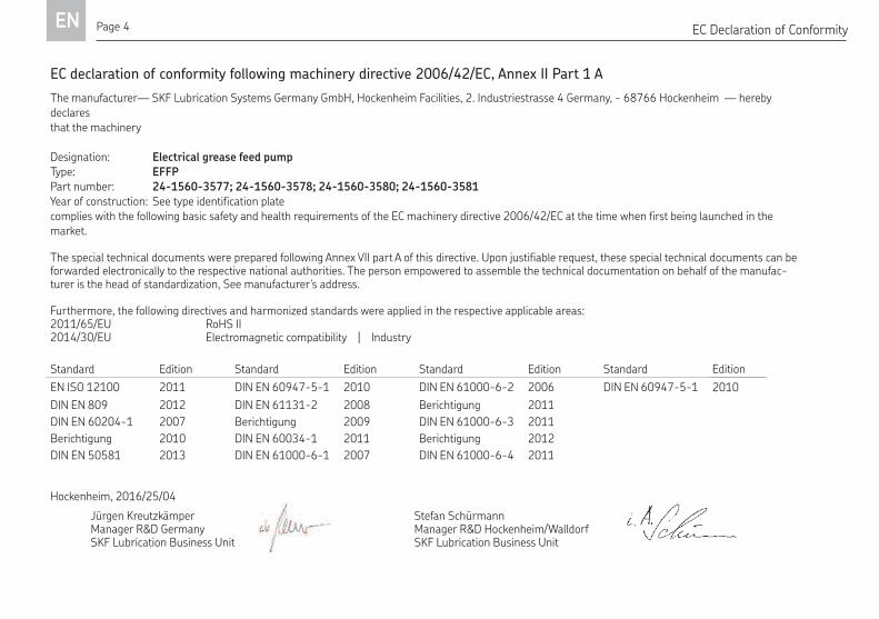
EC declaration of conformity following machinery directive 2006/42/EC, Annex II Part 1 A
The manufacturer— SKF Lubrication Systems Germany GmbH, Hockenheim Facilities, 2. Industriestrasse 4 Germany, - 68766 Hockenheim — hereby declares that the machinery
Designation: Electrical grease feed pump
Type: EFFPPart number: 24-1560-3577; 24-1560-3578; 24-1560-3580; 24-1560-3581 Year of construction: See type identification platecomplies with the following basic safety and health requirements of the EC machinery directive 2006/42/EC at the time when first being launched in the market.
The special technical documents were prepared following Annex VII part A of this directive. Upon justifiable request, these special technical documents can be forwarded electronically to the respective national authorities. The person empowered to assemble the technical documentation on behalf of the manufac-turer is the head of standardization, See manufacturer's address.
Furthermore, the following directives and harmonized standards were applied in the respective applicable areas:2011/65/EU RoHS II 2014/30/EU Electromagnetic compatibility | Industry Automotive
Standard Edition Standard Edition Standard Edition Standard Edition
EN ISO 12100 2011 DIN EN 60947-5-1 2010 DIN EN 61000-6-2 2006 DIN EN 60947-5-1 2010
DIN EN 809 2012 DIN EN 61131-2 2008 Berichtigung 2011
DIN EN 60204-1 2007 Berichtigung 2009 DIN EN 61000-6-3 2011
Berichtigung 2010 DIN EN 60034-1 2011 Berichtigung 2012
DIN EN 50581 2013 DIN EN 61000-6-1 2007 DIN EN 61000-6-4 2011
Hockenheim, 2016/25/04
Jürgen Kreutzkämper Manager R&D GermanySKF Lubrication Business Unit
Stefan Schürmann Manager R&D Hockenheim/Walldorf SKF Lubrication Business Unit
EC Declaration of Conformity
Page 5 EN
Safety signal words and their meaning
Explanation of symbols
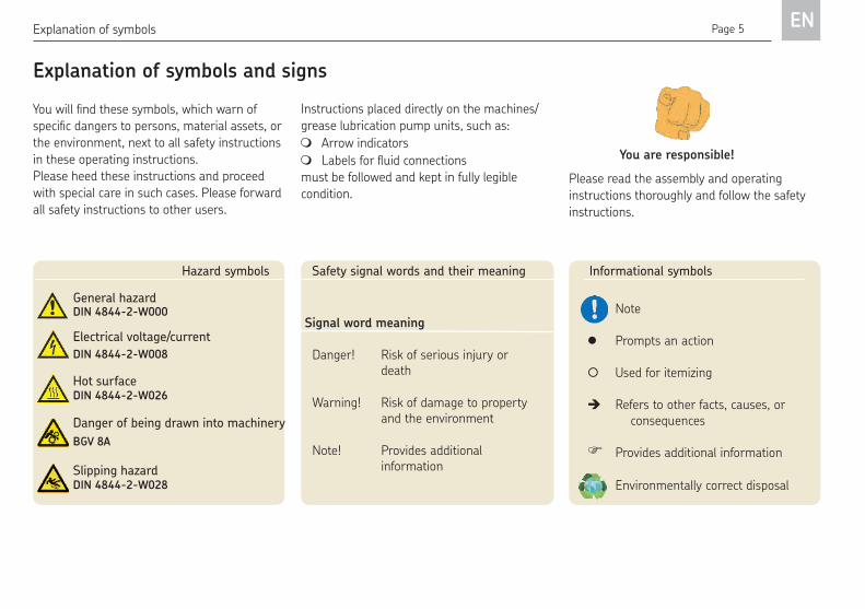
Explanation of symbols and signs
Youwillindthesesymbols,whichwarnofspeciicdangerstopersons,materialassets,orthe environment, next to all safety instructions
in these operating instructions.
Please heed these instructions and proceed
with special care in such cases. Please forward
all safety instructions to other users.
Signal word meaning
Danger! Risk of serious injury or death
Warning! Risk of damage to property and the environment
Note! Provides additional information
Instructions placed directly on the machines/
grease lubrication pump units, such as:
Arrow indicators
Labelsforluidconnectionsmust be followed and kept in fully legible
condition.
You are responsible!
Please read the assembly and operating
instructions thoroughly and follow the safety
instructions.
Informational symbols
Note
Prompts an action
Used for itemizing
Refers to other facts, causes, or consequences
Provides additional information
Environmentally correct disposal
Hazard symbols
General hazard DIN 4844-2-W000
Electrical voltage/current
Hot surface
Danger of being drawn into machinery
DIN 4844-2-W008
DIN 4844-2-W026
BGV 8A
Slipping hazardDIN 4844-2-W028
Page 6EN
The operator of the described prod-
uct must ensure that the operating
instructions are read and understood
by all persons responsible for assembly,
operation, maintenance, and repair of
the product. The operating instructions
must be kept readily available.
Note that the operating instructions
form part of the product and must
accompany the product if sold to a new
owner.
1. Safety instructions
In addition to the operating instructions,
statutory regulations and other general
regulations for accident prevention
and environmental protection must be
observed and applied.
The described product is manufactured in ac-
cordance with the generally accepted rules and
standards of industry practice and with occu-
pational safety and accident prevention regula-
tions. Risks may, however, arise from its usage
and may result in physical harm to persons or
damage to other material assets. Therefore the
product may only be used in proper technical
condition and in observance of the operating
instructions. In particular, any malfunctions
1.1 Authorized personnel
Only qualified technical personnel may install,
operate, maintain, and repair the products de-
scribed in the operating instructions. Qualified
technical personnel are persons who have
been trained, assigned, and instructed by the
operator of the final product into which the de-
scribed product is incorporated. Such persons
are familiar with the relevant standards, rules,
accident prevention regulations, and assembly
conditions as a result of their training, experi-
ence, and instruction. They are authorized to
identify and perform necessary actions while
avoiding any risks which may arise.
The definition of qualified personnel and the
prohibition against employing non-qualified
personnel are laid down in DIN VDE 0105 and
IEC 364.
1. Safety instructions
which may affect safety must be remedied
immediately.
Page 7 EN
1.2 Electric shock hazard
Electrical connections for the described prod-
uct may only be established by qualified and
trained personnel authorized to do so by the
operator, and in observance of the local elec-
trical operating conditions and local regulations
(e.g., DIN, VDE). Significant bodily injury and
property damage may result from improperly
connected products.
Danger!
Performing work on an energized
pump or product may result in serious
injury or death.
Assembly, maintenance and repair work
may only be performed on products
that have been de-energized by
qualiiedtechnicalpersonnel.Thesupply voltage must be switched off
before opening any of the product's
components.
1.3 System pressure hazard
Lubrication systems are pressurized
during operation. Centralized lubrication
systems must therefore be depressur-
ized before starting assembly, main-
tenance or repair work, or any system
modiicationsordecommissioning.
1. Safety instructions
1.4 Hoisting hazardThe EFFP electrical grease feed pump
can be transported using a crane. Never
stand under the EFFP during transport.
Ensure that nobody is present below
the load during transport.
1.5 Pre-commissioning informationCommissioning is prohibited until these
operating instructions have been read
and understood.
Inspect the electrical grease feed pump
for external damage before each use.
When filling lubricant into the pump, make
sure the lubricant is clean. The reservoir must
be filled in good time.
1.6 Replacing the grease pailWhen replacing the grease pail, ensure
that the palm grips are tightened and
have been secured against loosening
using the spring cotters; see Chapter
5.2, Assembly.
Page 8EN
1.7 Intended use
The EFFP electrical grease feed pump is suit-
able for mobile use. It is used to fill lubrication
pumps or as a lubricating aid for progressive
feeder systems.
Greases up to a maximum effective flow pres-
sure of 700 mbar are supported, including
greases based on mineral oil as well as envi-
ronmentally friendly and synthetic oils and
greases.
The pump fits common grease drums (also
referred to as hobbocks) with capacities from
16 to 25 kg.
The technical data presented in Chapter 10
must be observed for intended use.
Any other usage is deemed non-compliant
with the intended use.
Hazardous materials of any kind, especially the
materials classified as hazardous by CLP
Regulation EC 1272/2008 may only be used to
fill SKF centralized lubrication systems and
components and deliv-ered and/or distributed
with the same after consulting with and re-
ceiving written approval from SKF.
The product described here is neither designed
nor approved for use in conjunction with gases,
liquefied gases, pressurized gases in solution,
vapors and such fluids whose vapor pressure
exceeds normal atmospheric pressure (1013
mbar) by more than 0.5 bar at their maximum
permissible temperature.
Unless specially indicated otherwise, products
from SKF Lubrication Systems Germany GmbH
are not approved for use in potentially explo-
sive areas as defined in the ATEX Directive
2014/34/EC.
1. Safety instructions
1.8 Disclaimer of liability
SKF Lubrication Systems shall not be respon-
sible for damages:
Caused by contaminated or unsuitable
lubricants
Caused by the installation of non-original
SKF components or SKF spare parts
Caused by inappropriate usage
Resultingfromimproperassembly,conigu-
rationorilling Resulting from improper response to mal-
functions
Causedbyindependentmodiicationofsystem components
Only media approved for these types of
pump units may be used. Unsuitable
media may result in pump unit failure and
potentially severe bodily injury and property
damage.
Page 9 EN1. Safety instructions
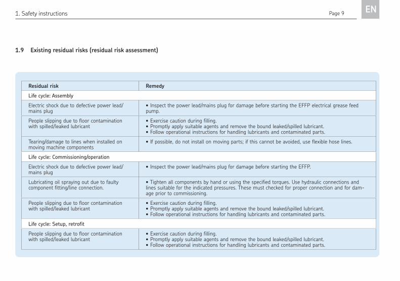
1.9 Existing residual risks (residual risk assessment)
Residual risk Remedy
Life cycle: Assembly
Electric shock due to defective power lead/mains plug
• Inspect the power lead/mains plug for damage before starting the EFFP electrical grease feed pump.
People slipping due to floor contamination with spilled/leaked lubricant
• Exercise caution during filling.• Promptly apply suitable agents and remove the bound leaked/spilled lubricant.• Follow operational instructions for handling lubricants and contaminated parts.
Tearing/damage to lines when installed on moving machine components
• If possible, do not install on moving parts; if this cannot be avoided, use flexible hose lines.
Life cycle: Commissioning/operation
Electric shock due to defective power lead/mains plug
• Inspect the power lead/mains plug for damage before starting the EFFP.
Lubricating oil spraying out due to faulty component fitting/line connection.
• Tighten all components by hand or using the specified torques. Use hydraulic connections and lines suitable for the indicated pressures. These must checked for proper connection and for dam-age prior to commissioning.
People slipping due to floor contamination with spilled/leaked lubricant
• Exercise caution during filling.• Promptly apply suitable agents and remove the bound leaked/spilled lubricant.• Follow operational instructions for handling lubricants and contaminated parts.
Life cycle: Setup, retrofit
People slipping due to floor contamination with spilled/leaked lubricant
• Exercise caution during filling.• Promptly apply suitable agents and remove the bound leaked/spilled lubricant.• Follow operational instructions for handling lubricants and contaminated parts.
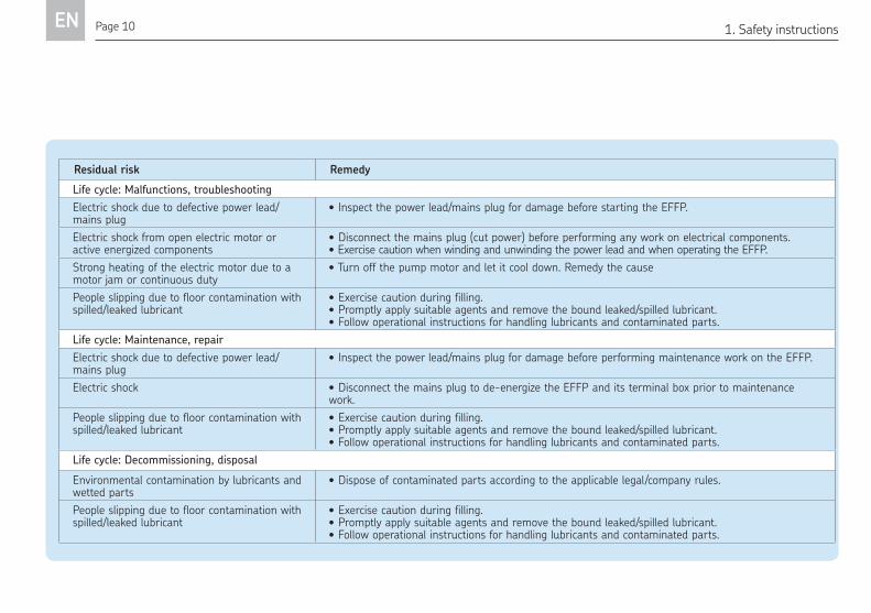
Page 10EN1. Safety instructions
Residual risk Remedy
Life cycle: Malfunctions, troubleshooting
Electric shock due to defective power lead/mains plug
• Inspect the power lead/mains plug for damage before starting the EFFP.
Electric shock from open electric motor or active energized components
• Disconnect the mains plug (cut power) before performing any work on electrical components.• Exercise caution when winding and unwinding the power lead and when operating the EFFP.
Strong heating of the electric motor due to a motor jam or continuous duty
• Turn off the pump motor and let it cool down. Remedy the cause
People slipping due to floor contamination with spilled/leaked lubricant
• Exercise caution during filling.• Promptly apply suitable agents and remove the bound leaked/spilled lubricant.• Follow operational instructions for handling lubricants and contaminated parts.
Life cycle: Maintenance, repair
Electric shock due to defective power lead/mains plug
• Inspect the power lead/mains plug for damage before performing maintenance work on the EFFP.
Electric shock • Disconnect the mains plug to de-energize the EFFP and its terminal box prior to maintenance work.
People slipping due to floor contamination with spilled/leaked lubricant
• Exercise caution during filling.• Promptly apply suitable agents and remove the bound leaked/spilled lubricant.• Follow operational instructions for handling lubricants and contaminated parts.
Life cycle: Decommissioning, disposal
Environmental contamination by lubricants and wetted parts
• Dispose of contaminated parts according to the applicable legal/company rules.
People slipping due to floor contamination with spilled/leaked lubricant
• Exercise caution during filling.• Promptly apply suitable agents and remove the bound leaked/spilled lubricant.• Follow operational instructions for handling lubricants and contaminated parts.
Page 11 EN2. Lubricants
2. Lubricants
2.1 General information
All products from SKF Lubrication
Systems may be used only for their
intended purpose and in accordance
with the information in the product's
operating instructions.
Intended use is the use of the products for the
purpose of providing centralized lubrication/
lubrication of bearings and friction points using
lubricants within the physical usage limits
which can be found in the documentation for
the devices, e.g., operating instructions and the
product descriptions, e.g., technical drawings
and catalogs.
Hazardous materials of any kind, especially the
materials classified as hazardous by CLP
Regulation EC 1272/2008 may only be used to
fill SKF centralized lubrication systems and
components and deliv-ered and/or distributed
with the same after consulting with and re-
ceiving written approval from SKF.
No products manufactured by SKF Lubrication
Systems are approved for use in conjunction
with gases, liquefied gases, pressurized gases
in solution, vapors, or such fluids whose vapor
pressure exceeds normal atmospheric pres-
sure (1013 mbar) by more than 0.5 bar at
their maximum permissible temperature.
Other media which are neither lubricant nor
hazardous substance may only be fed after
consulting with and obtaining written approval
from SKF Lubrication Systems.
SKF Lubrication Systems considers lubricants
to be an element of system design which must
always be factored into the selection of com-
ponents and the design of centralized lubrica-
tion systems. The lubricating properties of the
lubricants are critically important in making
these selections.
2.2 Selection of lubricantsObserve the instructions from the
machine manufacturer regarding the
lubricants that are to be used.
Warning!The amount of lubricant required at
alubricationpointisspeciiedbythebearing or machine manufacturer. It
must be ensured that that the required
quantity of lubricant is provided to the
lubrication point. The lubrication point
may otherwise not receive adequate
lubrication, which can lead to damage
and failure of the bearing.
Selection of a lubricant suitable for the lubrica-
tion task is made by the machine/system man-
ufacturer and/or the operator of the machine/
system in cooperation with the lubricant sup-
plier.
The bearings/friction points that require lubri-
cation, their expected load during operation,
and the expected ambient conditions are taken
into account during selection. All economic and
Page 12EN2. Lubricants
environmental aspects must also be
considered.
If required, SKF Lubrication Systems
can help customers to select suitable
components for feeding the selected
lubricant and to plan and design their
centralized lubrication system.
Please contact SKF Lubrication Systems if you
have further questions regarding lubricants.
Lubricants can be tested in the company's lab-
oratory for their suitability for pumping in cen-
tralized lubrication systems (e.g., "bleeding").
You can request an overview of the lubricant
tests offered by SKF Lubrication Systems from
the company's Service department.
2.3 Approved lubricants
Warning!Only lubricants approved for the prod-
uct may be used. Unsuitable lubricants
can lead to failure of the product and to
property damage.
Warning!Different lubricants must not be mixed
together. Doing so can cause damage
and require costly and complicated
cleaning of the product/lubrication sys-
tem. It is recommended that an indica-
tion of the lubricant in use be attached
to the lubricant reservoir in order to
prevent accidental mixing of lubricants.
The product described here can be operated
using lubricants that meet the specifications in
the technical data. Depending on the product
design, these lubricants may be oils, fluid greas-
es, or greases.
Oils and base oils may be mineral, synthetic
and/or rapidly biodegradable. Consistency
agents and additives may be added depending
on the operating conditions.
Note that in rare cases, there may be lubri-
cants whose properties are within permissible
limit values but whose other characteristics
render them unsuitable for use in centralized
lubrication systems. For example, synthetic lu-
bricants may be incompatible with elastomers.
Page 13 EN2. Lubricants
2.5 Lubricant hazardsDanger!Filling pumps must always be free of
leaks. Leaking lubricant is hazardous
due to the risk of slipping and injury.
Beware of any lubricant leaking out
during assembly, operation, mainte-
nance, or repair of centralized lubrica-
tion systems. Leaks must be sealed off
without delay.
Lubricant leaking from centralized lubrication
systems is a serious hazard. Leaking lubricant
can create risks that may result in physical
harm to persons or damage to other material
assets.
Warning!Follow the safety instructions on the
lubricant's safety data sheet.
Lubricants are a hazardous substance. The
safety instructions on the lubricant's safety
data sheet must be strictly followed. The safety
data sheet for a lubricant can be requested
from the lubricant manufacturer.
2.4 Lubricants and the environmentWarning!Lubricants can contaminate soil and
bodies of water. Lubricants must be
properly used and disposed of. Observe
the local regulations and laws regarding
the disposal of lubricants.
It is important to note that lubricants are envi-
ronmentally hazardous, flammable substances
which require special precautionary measures
during transport, storage, and processing.
Consult the safety data sheet from the lubri-
cant manufacturer for information regarding
transport, storage, processing, and environ-
mental hazards of the lubricant that will be
used.
The safety data sheet for a lubricant can be re-
quested from the lubricant manufacturer.
Page 14EN3. Transport, delivery, and storage
3. Transport, delivery, and storage
Warning!
The product must not be tilted or
dropped.
SKF Lubrication Systems products are pack-
aged in accordance with standard commercial
practice according to the regulations of the re-
cipient's country and DIN ISO 9001. During
transport, safe handling must be ensured and
the product must be protected from mechani-
cal effects such as impacts. The transport
packaging must be marked "Do not drop!"
There are no restrictions for land, air or sea
transport.
After receipt of the shipment, the product(s)
must be inspected for damage and for com-
pleteness according to the shipping docu-
ments. The packaging material must be pre-
served until any discrepancies are resolved.
SKF Lubrication Systems products are subject
to the following storage conditions:
3.1 Lubrication units
Ambient conditions: Dry and dust-free
surroundings, storage in well ventilated
dry area
Storage time: Max. 24 months
Permissible humidity: < 65%
Storage temperature: -10 to 60°C
Light: Avoid direct sun or UV exposure and
shield nearby sources of heat
3.2 Electronic and electrical devices
Ambient conditions: Dry and dust-free
surroundings, storage in well ventilated
dry area
Storage time: Max. 24 months
Permissible humidity: < 65%
Storage temperature: -10 to 60°C
Light: Avoid direct sun or UV exposure and
shield nearby sources of heat
3.3 General notes
The product(s) can be enveloped in
plasticfilm to provide low-dust storage.
Protect against ground moisture by
storing on a shelf or wooden pallet.
Bright-finished metallic surfaces, espe-
cially wearing parts and assembly
surfaces, must be protected using long-
term anti-corrosive agents before storage.
At approx. 6-month intervals: Check for
corrosion. If there are signs of corrosion,
reapply anti-corrosive agents.
Drives must be protected from mechani-
cal damage.
Page 15 EN4. Overview/Functional description
Made in Germany
SKF Lubrication Systems Germany AG
XYZ 25/09
24-1560-3556Elektr. Befüllpumpe230 VAC / 50 Hz
4. Overview/Functional description
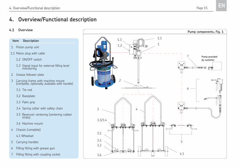
Item Description
1 Piston pump unit
1.1 Mains plug with cable
1.2 ON/OFF switch
1.3 Signal input for external filling level monitoring
2 Grease follower plate
3 Carrying frame with machine mount (complete, optionally available with handle)
3.1 Tie-rod
3.2 Baseplate
3.3 Palm grip
3.4 Spring cotter with safety chain
3.5 Reservoir centering (centering rubber strips)
3.6 Machine mount
4 Chassis (complete)
4.1 Wheelset
5 Carrying handles
6 Filling fitting with grease gun
7 Filling fitting with coupling socket
Pump components, Fig. 1
1
2
3 4
5
6
7
1.1
1.2
4.1
3.1
3.2
3.3/3.4
3.5
4.1 Overview
3.6
1.3
Pump provided
by customer
Page 16EN4. Overview/Functional description
4.2 Design of EFFP
The EFFP electrical grease feed pump is de-
signed as a piston pump for grease pail capaci-
ties from 16 to 25 kg. It is driven by a
230 V/50 Hz AC motor which powers a worm
drive with an eccentric shaft. The eccentric
shaft then controls a delivery piston which
generates a delivery stroke at the end of the
intake tube.
The EFFP is activated using an ON/OFF switch
attached to the terminal box.
An automatic switch-off function is integrated
standard. The pump motor is switched off once
the non-adjustable cutoff pressure of 100 bar
is reached. The motor is switched on automati-
cally after pressure drops (below the cutoff
pressure). This technology makes it possible to,
for example, use a high-pressure gun to lubri-
cate individual lubrication points.
The EFFP has a modular design. The basic
design is supplied with a carrying frame. The
EFFP is optionally available with external signal
monitoring, which can be used for maximum
fill level monitoring using customer equipment,
for example.
A wheelset and carrying handles as well as a
comprehensive range of accessories are also
available (see page 15 and the Accessories
chapter).
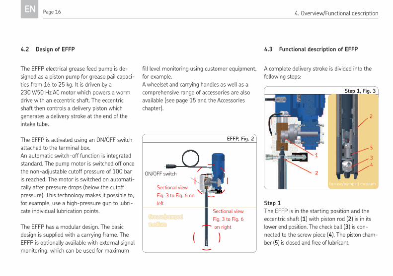
4.3 Functional description of EFFP
A complete delivery stroke is divided into the
following steps:
Step 1
The EFFP is in the starting position and the
eccentric shaft (1) with piston rod (2) is in its
lower end position. The check ball (3) is con-
nected to the screw piece (4). The piston cham-
ber (5) is closed and free of lubricant.
EFFP, Fig. 2
Step 1, Fig. 3
Sectional view
Fig. 3 to Fig. 6
on right
Sectional view
Fig. 3 to Fig. 6 on
left
Grease/pumped medium
Grease/pumped
medium
ON/OFF switch
Page 17 EN4. Overview/Functional description
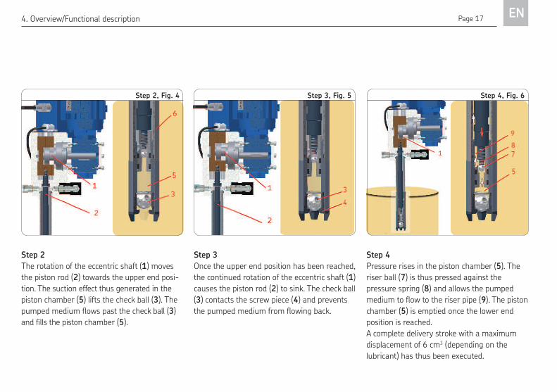
Step 4
Pressure rises in the piston chamber (5). The
riser ball (7) is thus pressed against the
pressure spring (8) and allows the pumped
medium to flow to the riser pipe (9). The piston
chamber (5) is emptied once the lower end
position is reached.
A complete delivery stroke with a maximum
displacement of 6 cm3 (depending on the
lubricant) has thus been executed.
Step 3
Once the upper end position has been reached,
the continued rotation of the eccentric shaft (1)
causes the piston rod (2) to sink. The check ball
(3) contacts the screw piece (4) and prevents
the pumped medium from flowing back.
Step 2
The rotation of the eccentric shaft (1) moves
the piston rod (2) towards the upper end posi-
tion. The suction effect thus generated in the
piston chamber (5) lifts the check ball (3). The
pumped medium flows past the check ball (3)
and fills the piston chamber (5).
Step 2, Fig. 4 Step 3, Fig. 5 Step 4, Fig. 6
Page 18EN5. Assembly
5. Assembly
5.1 General information
Danger!See safety instructions in Chapter 1.1.
Disconnect the mains plug from the
power outlet.
The EFFP grease feed pump is used to fill
pumps, as a lubricating aid for progressive
feeders, or as a mobile pump for service calls.
The EFFP and its accessories are available in
various designs as the following kits:
EFFP electrical grease feed pump
optional versions
o Pump design 100 bar /0,4 l/min
o Pump design 250 bar /0,2 l/min
o Pump design 250 bar /0,4 l/min
with/without
o Pump design with signal input
(external control)
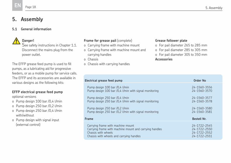
Electrical grease feed pump Order No
Pump design 100 bar /0,4 l/min 24-1560-3556Pump design 100 bar /0,4 l/min with signal monitoring 24-1560-3570
Pump design 250 bar /0,4 l/min 24-1560-3577Pump design 250 bar /0,4 l/min with signal monitoring 24-1560-3578
Pump design 250 bar /0,2 l/min 24-1560-3580Pump design 250 bar /0,2 l/min with signal monitoring 24-1560-3581
Frame Bestell Nr.
Carrying frame with machine mount 24-1722-2545Carrying frame with machine mount and carrying handles 24-1722-2550 Chassis with wheels 24-1722-2552Chassis with wheels and carrying handles 24-1722-2551
Frame for grease pail (complete)
o Carrying frame with machine mount
o Carrying frame with machine mount and
carrying handles
o Chassis
o Chassis with carrying handles
Grease follower plate
o For pail diameter 265 to 285 mm
o For pail diameter 285 to 305 mm
o For pail diameter 305 to 350 mm
Accessories
Page 19 EN
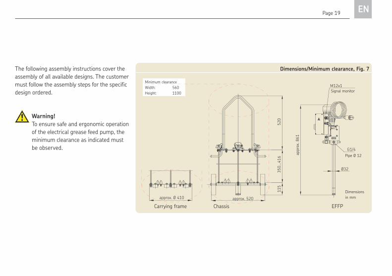
The following assembly instructions cover the
assembly of all available designs. The customer
must follow the assembly steps for the specific
design ordered.
Dimensions/Minimum clearance, Fig. 7
Made in Germany
SKF Lubrication Systems Germany AG
XYZ 25/09
24-1560-3556Elektr. Befüllpumpe230 VAC / 50 Hz
appr
ox. 8
61
Ø32
G1/4
350.
..416
520
115
approx. Ø 410 approx. 520
M12x1Signal monitor
Pipe Ø 12
Dimensions
in mm
Warning! To ensure safe and ergonomic operation
of the electrical grease feed pump, the
minimum clearance as indicated must
be observed.
Minimum clearance
Width: 560
Height: 1100
Carrying frame Chassis EFFP
Page 20EN5. Assembly
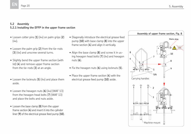
5.2 Assembly
5.2.1 Installing the EFFP in the upper frame sectionAssembly of upper frame section, Fig. 8
Made in Germany
SKF Lubrication Systems Germany AG
XYZ 25/09
24-1560-3556Elektr. Befüllpumpe230 VAC / 50 Hz
Made in Germany
SKF Lubrication Systems Germany AG
XYZ 25/09
24-1560-3556Elektr. Befüllpumpe230 VAC / 50 Hz
• Loosen cotter pins (1) (4x) on palm grips (2)
(4x).
• Loosen the palm grip (2) from the tie-rods
(3) (4x) and unscrew several turns.
• Slightly bend the upper frame section (with
lid) (4) and remove upper frame section
from the tie-rods (3) at an angle.
• Loosen the locknuts (5) (4x) and place them
aside.
• Loosen the hexagon nuts (6) (4x) (WAF 13)
from the hexagon head bolts (7) (WAF 13)
and place the bolts and nuts aside.
• Loosen the base clamp (8) from the upper
frame section (4) and insert it into the cylinder
liner (9) of the electrical grease feed pump (10).
• Diagonally introduce the electrical grease feed
pump (10) with base clamp (8) into the upper
frame section (4) and align it vertically.
• Align the base clamp (8) and screw it in us-
ing hexagon head bolts (7) (4x) and hexagon
nuts (6).
• Fix the hexagon nuts (6) using locknuts (5).
• Place the upper frame section (4) with the
electrical grease feed pump (10) aside.
1
2
3
4
5/6
7
8
8
9
10
Mains plug
Machine mount
Carrying handles
Page 21 EN5. Assembly
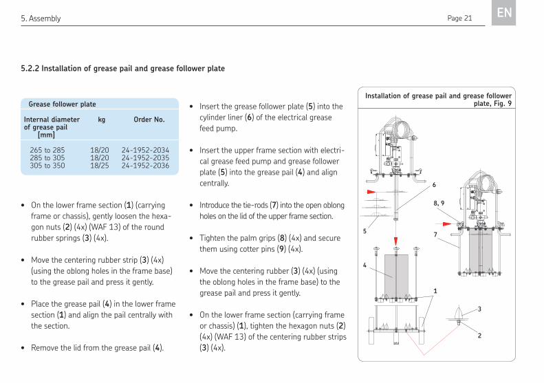
5.2.2 Installation of grease pail and grease follower plate
Installation of grease pail and grease follower plate, Fig. 9 Grease follower plate
Internal diameter kg Order No. of grease pail [mm]
265 to 285 18/20 24-1952-2034285 to 305 18/20 24-1952-2035305 to 350 18/25 24-1952-2036
Made in Germany
SKF Lubrication Systems Germany AG
XYZ 25/09
24-1560-3556Elektr. Befüllpumpe230 VAC / 50 Hz
Made in Germany
SKF Lubrication Systems Germany AG
XYZ 25/09
24-1560-3556Elektr. Befüllpumpe230 VAC / 50 Hz
• On the lower frame section (1) (carrying
frame or chassis), gently loosen the hexa-
gon nuts (2) (4x) (WAF 13) of the round
rubber springs (3) (4x).
• Move the centering rubber strip (3) (4x)
(using the oblong holes in the frame base)
to the grease pail and press it gently.
• Place the grease pail (4) in the lower frame
section (1) and align the pail centrally with
the section.
• Remove the lid from the grease pail (4).
• Insert the grease follower plate (5) into the
cylinder liner (6) of the electrical grease
feed pump.
• Insert the upper frame section with electri-
cal grease feed pump and grease follower
plate (5) into the grease pail (4) and align
centrally.
• Introduce the tie-rods (7) into the open oblong
holes on the lid of the upper frame section.
• Tighten the palm grips (8) (4x) and secure
them using cotter pins (9) (4x).
• Move the centering rubber (3) (4x) (using
the oblong holes in the frame base) to the
grease pail and press it gently.
• On the lower frame section (carrying frame
or chassis) (1), tighten the hexagon nuts (2)
(4x) (WAF 13) of the centering rubber strips
(3) (4x).
1
2
3
4
7
8, 96
5
Page 22EN5. Assembly
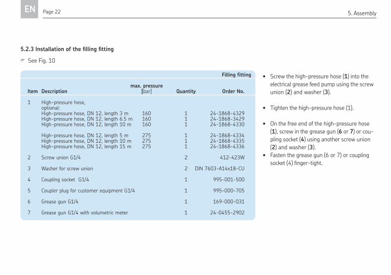
5.2.3 Installation of the illing itting
• Screw the high-pressure hose (1) into the
electrical grease feed pump using the screw
union (2) and washer (3).
• Tighten the high-pressure hose (1).
• On the free end of the high-pressure hose
(1), screw in the grease gun (6 or 7) or cou-
pling socket (4) using another screw union
(2) and washer (3).
• Fasten the grease gun (6 or 7) or coupling
socket(4)inger-tight.
Filling fitting
max. pressure Item Description [bar] Quantity Order No.
1 High-pressure hose, optional: High-pressure hose, DN 12, length 3 m 160 1 24-1868-4329 High-pressure hose, DN 12, length 6.5 m 160 1 24-1868-3429 High-pressure hose, DN 12, length 10 m 160 1 24-1868-4330
High-pressure hose, DN 12, length 5 m 275 1 24-1868-4334 High-pressure hose, DN 12, length 10 m 275 1 24-1868-4335 High-pressure hose, DN 12, length 15 m 275 1 24-1868-4336
2 Screw union G1/4 2 412-423W
3 Washer for screw union 2 DIN 7603-A14x18-CU
4 Coupling socket G1/4 1 995-001-500
5 Coupler plug for customer equipment G1/4 1 995-000-705
6 Grease gun G1/4 1 169-000-031
7 Grease gun G1/4 with volumetric meter 1 24-0455-2902
See Fig. 10
Page 23 EN5. Assembly/6. Operation
Made in Germany
SKF Lubrication Systems Germany AG
XYZ 25/09
24-1560-3556Elektr. Befüllpumpe230 VAC / 50 Hz
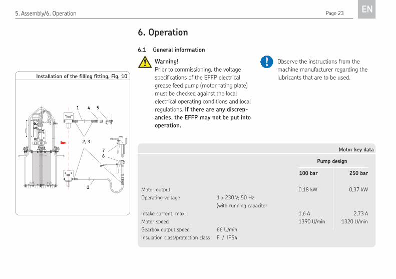
Installation of the filling fitting, Fig. 10
1
4
6
5
7
2, 3
1
6.1 General informationWarning!Prior to commissioning, the voltage
speciicationsoftheEFFPelectricalgrease feed pump (motor rating plate)
must be checked against the local
electrical operating conditions and local
regulations. If there are any discrep-ancies, the EFFP may not be put into operation.
6. Operation
Observe the instructions from the
machine manufacturer regarding the
lubricants that are to be used.
Motor key data Pump design 100 bar 250 bar
Motor output 0,18 kW 0,37 kW
Operating voltage 1 x 230 V; 50 Hz
(with running capacitor
Intake current, max. 1,6 A 2,73 A
Motor speed 1390 U/min 1320 U/min
Gearbox output speed 66 U/min
Insulation class/protection class F / IP54
Page 24EN6. Operation
Warning!Observe the max. mark on the pump
thatwillbeilled.Donotoverillunderanycircumstances!If the pressure-limiting valve is missing,
there is a risk of the pump reservoir
breaking.
The described product functions automatically.
The lubricant transport should, however, be
subjected to regular visual inspection.
The lubricant fill level in the lubricant reservoir
should likewise be subjected to regular visual
inspection. If the lubricant fill level is too low,
lubricant needs to be added up to the maxi-
mum mark or the grease pail needs to be
replaced.
Warning!Onlyillusingcleanlubricantandanappropriate device. Contaminated
lubricants can result in severe system
malfunction.
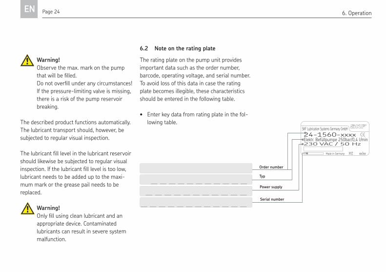
6.2 Note on the rating plateThe rating plate on the pump unit provides
important data such as the order number,
barcode, operating voltage, and serial number.
To avoid loss of this data in case the rating
plate becomes illegible, these characteristics
should be entered in the following table.
• Enter key data from rating plate in the fol-
lowing table.
Order number
Power supplySerial number
Made in Germany
SKF Lubrication Systems Germany GmbH
XYZ xx/xx
24-1560-xxxxElektr. Befüllpumpe 250bar/0,4 l/min230 VAC / 50 Hz
Page 25 EN6. Operation
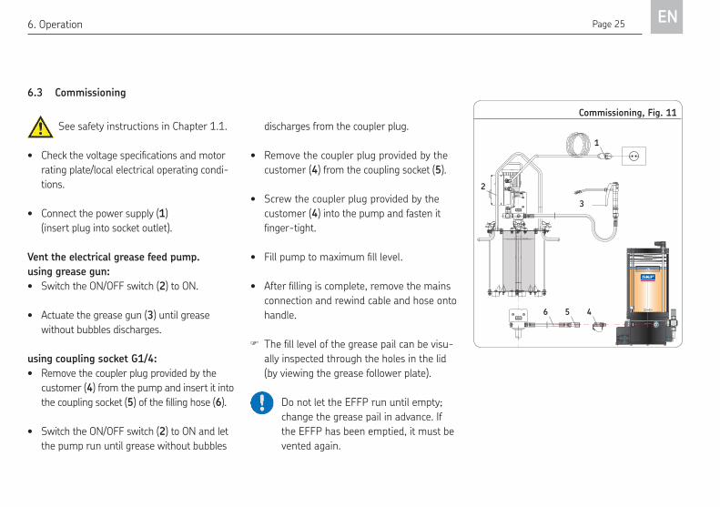
Commissioning, Fig. 11
Made in Germany
SKF Lubrication Systems Germany AG
XYZ 25/09
24-1560-3556Elektr. Befüllpumpe230 VAC / 50 Hz
Füllstand Maximum, Unterkante Fettfolgeteller
filling level maximum, lower border follower plate
See safety instructions in Chapter 1.1.
• Checkthevoltagespeciicationsandmotorrating plate/local electrical operating condi-
tions.
• Connect the power supply (1)
(insert plug into socket outlet).
Vent the electrical grease feed pump.using grease gun:• Switch the ON/OFF switch (2) to ON.
• Actuate the grease gun (3) until grease
without bubbles discharges.
using coupling socket G1/4:• Remove the coupler plug provided by the
customer (4) from the pump and insert it into
the coupling socket (5)oftheillinghose(6).
• Switch the ON/OFF switch (2) to ON and let
the pump run until grease without bubbles
3
1
2
456
discharges from the coupler plug.
• Remove the coupler plug provided by the
customer (4) from the coupling socket (5).
• Screw the coupler plug provided by the
customer (4) into the pump and fasten it
inger-tight.• Fillpumptomaximumilllevel.• Afterillingiscomplete,removethemains
connection and rewind cable and hose onto
handle.
Theilllevelofthegreasepailcanbevisu-
ally inspected through the holes in the lid
(by viewing the grease follower plate).
Do not let the EFFP run until empty;
change the grease pail in advance. If
the EFFP has been emptied, it must be
vented again.
6.3 Commissioning
Page 26EN6. Operation
6.4 Grease reservoir replacement
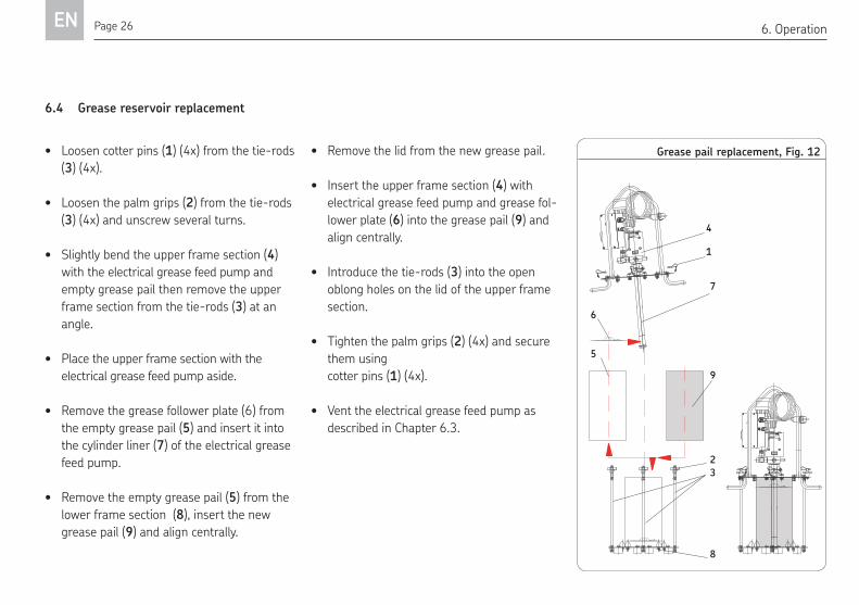
Grease pail replacement, Fig. 12
Made in Germany
SKF Lubrication Systems Germany AG
XYZ 25/09
24-1560-3556Elektr. Befüllpumpe230 VAC / 50 Hz
Made in Germany
SKF Lubrication Systems Germany AG
XYZ 25/09
24-1560-3556
Elektr. Befüllpumpe
230 VAC / 50 Hz
1
2
3
4
8
7
6
• Loosen cotter pins (1) (4x) from the tie-rods
(3) (4x).
• Loosen the palm grips (2) from the tie-rods
(3) (4x) and unscrew several turns.
• Slightly bend the upper frame section (4)
with the electrical grease feed pump and
empty grease pail then remove the upper
frame section from the tie-rods (3) at an
angle.
• Place the upper frame section with the
electrical grease feed pump aside.
• Remove the grease follower plate (6) from
the empty grease pail (5) and insert it into
the cylinder liner (7) of the electrical grease
feed pump.
• Remove the empty grease pail (5) from the
lower frame section (8), insert the new
grease pail (9) and align centrally.
• Remove the lid from the new grease pail.
• Insert the upper frame section (4) with
electrical grease feed pump and grease fol-
lower plate (6) into the grease pail (9) and
align centrally.
• Introduce the tie-rods (3) into the open
oblong holes on the lid of the upper frame
section.
• Tighten the palm grips (2) (4x) and secure
them using
cotter pins (1) (4x).
• Vent the electrical grease feed pump as
described in Chapter 6.3.
59
Page 27 EN7. Shutdown and disposal
7. Shutdown and disposal
7.1 Temporary shutdown The described product can be shut down tem-
porarily by disconnecting the electrical supply
connection (disconnecting the mains plug).
If the product will be shut down for an extend-
ed period of time, the instructions in Chapter 3,
"Transport and storage," must be observed.
To recommission the product, follow the safety
instructions in Chapter 1 as well as Chapter
6.3, "Commissioning, venting."
7.2 Permanent shutdown If the product will be permanently shut down,
the local regulations and laws regarding the
disposal of contaminated equipment must be
observed.
Warning!
Lubricants can contaminate soil and
bodies of water. Lubricants must be
properly used and disposed of. Observe
the local regulations and laws regarding
the disposal of lubricants.
The product can also be returned to SKF
Lubrication Systems Germany GmbH for dis-
posal, in which case the customer is respon-
sible for reimbursing the costs incurred.
The parts are recyclable.
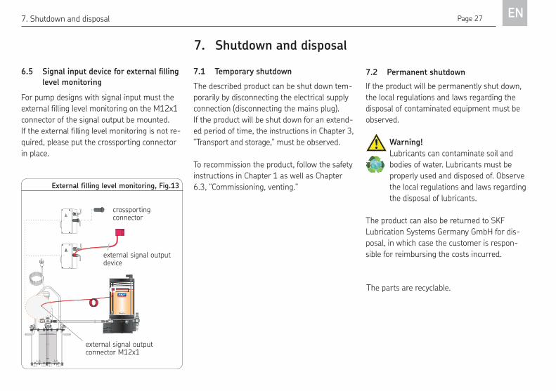
6.5 Signal input device for external illing level monitoringFor pump designs with signal input must the
external filling level monitoring on the M12x1
connector of the signal output be mounted.
If the external filling level monitoring is not re-
quired, please put the crossporting connector
in place.
External filling level monitoring, Fig.13
Made in Germany
SKF Lubrication Systems Germany AG
XYZ 25/09
24-1560-3556Elektr. Befüllpumpe230 VAC / 50 Hz
Füllstand Maximum, Unterkante Fettfolgeteller
filling level maximum, lower border follower plate
external signal output device
crossporting connector
external signal output connector M12x1
Page 28EN8. Maintenance
8. Maintenance
See safety instructions in Chapter 1.1.
Danger!Performing work on an energized pump
or product may result in serious injury
or death. Assembly, maintenance and
repair work may only be performed on
products that have been de-energized
byqualiiedtechnicalpersonnel.Supplyvoltage must be switched off before
opening any of the product's compo-
nents.
Products from SKF Lubrication Systems are
low-maintenance. However, all connections
and fittings must be regularly inspected for
proper seating to ensure proper function and
to prevent hazards from arising.
If necessary, the product can be cleaned using
mild cleaning agents that are compatible with
the product's materials (non-alkaline, non-soap).
For safety reasons, the product must be dis-
connected from the power supply and the hy-
draulic connection.
Do not allow any cleaning agent to enter the
interior of the product during cleaning.
It is not necessary to clean the interior of the
product if the product is operated normally and
intercompatible lubricants are used.
The interior of the product must be cleaned if
incorrect or contaminated lubricant is acciden-
tally filled into the product. If this occurs,
please contact the Service department of SKF
Lubrication Systems for assistance.
Dismantling of the product or individual
parts thereof within the statutory war-
ranty period is not permitted and voids
any claims.
The electrical grease feed pump functions
without maintenance in principle. In order to
prevent air intake, ensure that the grease level
does not fall below the cylinder liner's intake
hole.
Only original spare parts from SKF
Lubrication Systems may be used. Un-
authorized alterations to products and
the use of non-original spare parts and
accessories are prohibited and nullify
the statutory warranty.
SKF Lubrication Systems shall not be respon-
sible for any damages resulting from improper
assembly, maintenance, or repair work on the
product.
8.1 General information
Page 29 EN8. Maintenance
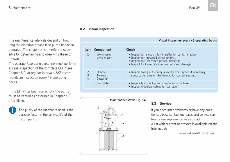
The maintenance intervals depend on how
long the electrical grease feed pump has been
operated. The customer is therefore respon-
sible for determining and observing these on
its own.
The operator/operating personnel must perform
a visual inspection of the complete EFFP (see
Chapter 8.2) at regular intervals. SKF recom-
mends an inspection every 48 operating
hours.
If the EFFP has been run empty, the pump
must be vented as described in Chapter 6.3
after filling.
The purity of the lubricants used is the
decisive factor in the service life of the
piston pump.
8.3 ServiceIf you encounter problems or have any ques-
tions, please contact our sales and service cen-
ters or our representatives abroad.
A list with current addresses is available on the
Internet at:
www.skf.com/lubrication
Visual inspection every 48 operating hoursItem Component Check
1 Worm gear drive motor
• Inspect fan slots on fan impeller for contamination • Inspect for loosened screw unions. • Inspect for undesired grease discharge. • Inspect for loose cable connections and damage.
2 34
HandleTie-rodCotter pin
• Inspect fixing nuts every 4 weeks and tighten if necessary. Inspect cotter pins on the tie-rod for correct seating.
Complete • Regularly inspect pump components for leaks.• Inspect electrical cables for damage.
8.2 Visual inspection
Made in Germany
SKF Lubrication Systems Germany AG
XYZ 25/09
24-1560-3556Elektr. Befüllpumpe230 VAC / 50 Hz
Maintenance items Fig. 14
1
2
3
4
Page 30EN9. Malfunctions, causes, and remedies
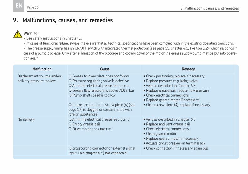
9. Malfunctions, causes, and remedies
Warning!
- See safety instructions in Chapter 1.
-Incasesoffunctionalfailure,alwaysmakesurethatalltechnicalspeciicationshavebeencompliedwithintheexistingoperatingconditions.- The grease supply pump has an ON/OFF switch with integrated thermal protection (see page 15, chapter 4.1, Position 1.2), which responds in
case of a pump blockage. Only after elimination of the blockage and cooling down of the motor the grease supply pump may be put into opera-
tion again.
Malfunction Cause Remedy Displacement volume and/or
delivery pressure too low
Grease follower plate does not follow
Pressure regulating valve is defective
Air in the electrical grease feed pumpGreaselowpressureisabove700mbar Pump shaft speed is too low
Intake area on pump screw piece (4) (see
page 17) is clogged or contaminated with
foreign substances
• Check positioning, replace if necessary
• Replace pressure regulating valve
• Vent as described in Chapter 6.3•Replacegreasepail,reducelowpressure• Check electrical connections
• Replace geared motor if necessary
• Clean screw piece (4), replace if necessary
No delivery Air in the electrical grease feed pump
Empty grease pail
Drive motor does not run
• Vent as described in Chapter 6.3
• Replace and vent grease pail
• Check electrical connections
• Clean geared motor
• Replace geared motor if necessary
• Actuate circuit breaker on terminal box
crossporting connector or external signal
input (see chapter 6.5) not connected
• Check connection, if necessary again pull
Page 31 EN10. Technical data
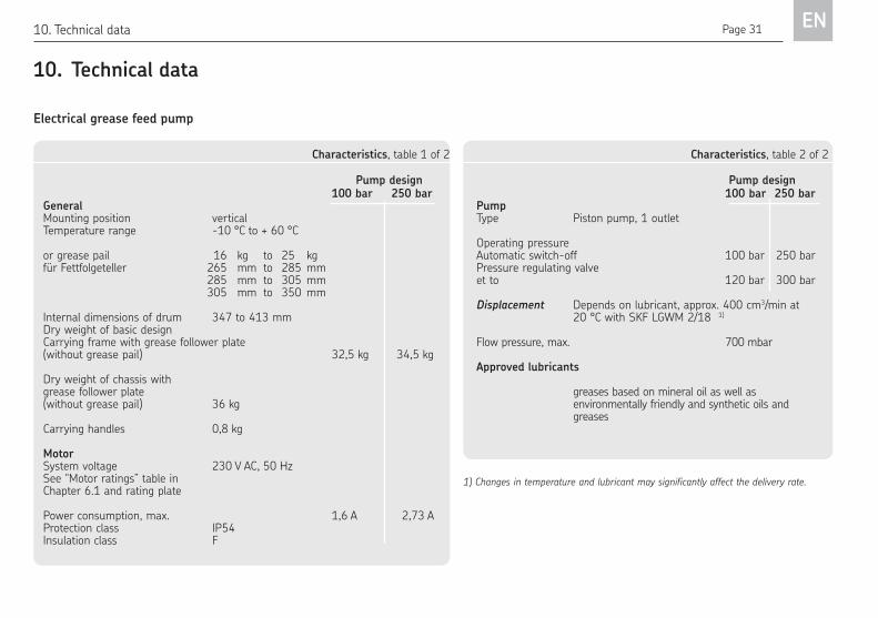
10. Technical dataElectrical grease feed pump
1) Changes in temperature and lubricant may significantly affect the delivery rate.
Characteristics, table 1 of 2
Pump design 100 bar 250 barGeneralMounting position verticalTemperature range -10 °C to + 60 °C
or grease pail 16 kg to 25 kg für Fettfolgeteller 265 mm to 285 mm 285 mm to 305 mm 305 mm to 350 mm
Internal dimensions of drum 347 to 413 mmDry weight of basic design Carrying frame with grease follower plate (without grease pail) 32,5 kg 34,5 kg
Dry weight of chassis with grease follower plate (without grease pail) 36 kg
Carrying handles 0,8 kg
Motor System voltage 230 V AC, 50 HzSee “Motor ratings” table in Chapter 6.1 and rating plate
Power consumption, max. 1,6 A 2,73 AProtection class IP54Insulation class F
Characteristics, table 2 of 2
Pump design 100 bar 250 barPumpType Piston pump, 1 outlet
Operating pressureAutomatic switch-off 100 bar 250 barPressure regulating valve et to 120 bar 300 bar
Displacement Depends on lubricant, approx. 400 cm3/min at 20 °C with SKF LGWM 2/18 1)
Flow pressure, max. 700 mbar
Approved lubricants
greases based on mineral oil as well as environmentally friendly and synthetic oils and greases
Page 32EN11. Spare parts
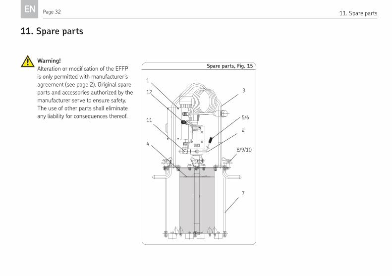
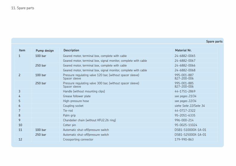
11. Spare parts
Spare parts, Fig. 15 Warning!AlterationormodiicationoftheEFFPis only permitted with manufacturer's
agreement (see page 2). Original spare
parts and accessories authorized by the
manufacturer serve to ensure safety.
The use of other parts shall eliminate
any liability for consequences thereof.
Made in Germany
SKF Lubrication Systems Germany AG
XYZ 25/09
24-1560-3556Elektr. Befüllpumpe230 VAC / 50 Hz
1
5/6
3
2
4
7
8/9/10
11
12
11. Spare parts
Spare parts
Item Pump design Description Material Nr.
1 100 bar Geared motor, terminal box, complete with cable 24-6882-0065
Geared motor, terminal box, signal monitor, complete with cable 24-6882-0067
250 bar Geared motor, terminal box, complete with cable 24-6882-0066
Geared motor, terminal box, signal monitor, complete with cable 24-6882-0068
2 100 bar Pressure regulating valve 120 bar, (without spacer sleeve)Spacer sleeve
995-001-887827-200-006
250 bar Pressure regulating valve 300 bar, (without spacer sleeve)Spacer sleeve
995-001-885827-200-006
3 Handle (without mounting clips) 44-1751-2869
4 Grease follower plate see pages 21/34
5 High-pressure hose see pages 22/34
6 Coupling socket siehe Seite 22/Seite 34
7 Tie-rod 44-0717-2322
8 Palm grip 95-2051-6335
9 Chandelier chain (without KFU2.26 ring) 996-000-214
10 Cotter pin 95-0025-11024
11 100 bar Automatic shut-off/pressure switch DSB1-S10000X-1A-01
250 bar Automatic shut-off/pressure switch DSB1-S25000X-1A-01
12 Crossporting connector 179-990-863
Page 34EN12. Accessories
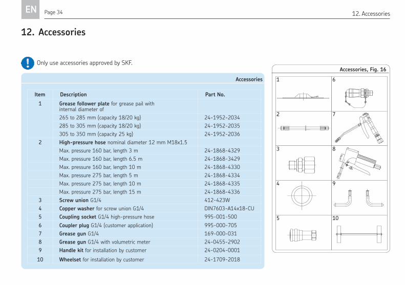
12. Accessories
AccessoriesItem Description Part No.
1 Grease follower plate for grease pail with internal diameter of
265 to 285 mm (capacity 18/20 kg) 24-1952-2034
285 to 305 mm (capacity 18/20 kg) 24-1952-2035
305 to 350 mm (capacity 25 kg) 24-1952-2036
2 High-pressure hose nominal diameter 12 mm M18x1.5
Max. pressure 160 bar, length 3 m 24-1868-4329
Max. pressure 160 bar, length 6.5 m 24-1868-3429
Max. pressure 160 bar, length 10 m 24-1868-4330
Max. pressure 275 bar, length 5 m 24-1868-4334
Max. pressure 275 bar, length 10 m 24-1868-4335
Max. pressure 275 bar, length 15 m 24-1868-4336
3 Screw union G1/4 412-423W
4 Copper washer for screw union G1/4 DIN7603-A14x18-CU
5 Coupling socket G1/4 high-pressure hose 995-001-500
6 Coupler plug G1/4 (customer application) 995-000-705
7 Grease gun G1/4 169-000-031
8 Grease gun G1/4 with volumetric meter 24-0455-2902
9 Handle kit for installation by customer 24-0204-0001
10 Wheelset for installation by customer 24-1709-2018
Accessories, Fig. 16
1 6
2 7
3 8
4 9
5 10
Only use accessories approved by SKF.

951-180-061-EN
SKF Lubrication Systems Germany GmbH
2. Industriestrasse 4 · 68766 Hockenheim · Germany
Tel. +49 (0)62 05 27-0 · Fax +49 (0)62 05 27-101
www.skf.com/lubrication
SKF Lubrication Systems Germany GmbH
Motzener Strasse 35/37 · 12277 Berlin · Germany
PO Box 970444 · 12704 Berlin · Germany
Tel. +49 (0)30 72002-0 · Fax +49 (0)30 72002-111
www.skf.com/lubrication
The contents of this publication are the copyright of the publisher and may not be re-
produced in whole or in part without permission of SKF Lubrication Systems Germany
GmbH. Every care has been taken to ensure the accuracy of the information contained
in this publication. but no liability can be accepted for any loss or damage whether di-
rect, indirect or consequential, arising out of use of the information contained herein.
All SKF products may be used only for their intended purpose as described in these
operating instructions with associated operating instructions. If assembly/operating in-
structions are supplied together with the products, they must be read and followed.
Not all lubricants can be fed using centralized lubrication systems. SKF can, on re-
quest, inspect the suitability of the lubricant selected by the user for pumping in cen-
tralized lubrication systems. Lubrication systems and their components manufactured
by SKF are not approved for use in conjunction with gases, liquefied gases, pressurized
gases in solution, vapors, or such fluids whose vapor pressure exceeds normal atmo-
spheric pressure (1013 mbar) by more than 0.5 bar at their maximum permissible
temperature.
Hazardous materials of any kind, especially the materials classified as hazardous by
CLP Regulation EC 1272/2008 may only be used to fill SKF centralized lubrication
systems and components and deliv-ered and/or distributed with the same after
consulting with and receiving written approval from SKF.